Revised: Page 1
|
|
|
- Melvyn Barber
- 5 years ago
- Views:
Transcription


1 Brought To You By And Designed By: Revised: Page 1
 Meets or surpasses all Apple II and /// power requirements. Modern PSU design. Standard 2 year warranty.")
 Fast Power Reset: No more hung systems or need for long off periods and waiting before turning back on.")


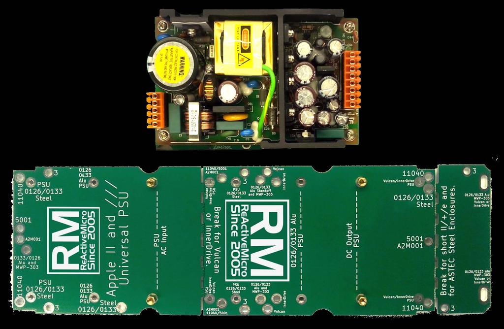
2 Features Of The Universal PSU Kit: Fits all standard Apple II and /// Power Supply Enclosures. (all parts included, user supplies household tools) Meets or surpasses all Apple II and /// power requirements. Modern PSU design. Standard 2 year warranty. Universal PSU operates on a wide range of input power: VAC, 47-63Hz. On-board Power LED shows when AC is applied to the Universal PSU and is working. Constant Voltage design (regulated) Fast Power Reset: No more hung systems or need for long off periods and waiting before turning back on. Interchangeable DC Output Cable for II/+/e/gs/III. One PSU can support all! Runs cool/low heat output: Operates cooler than the old Apple II PSU. Cleaner and more consistent power than the old Apple II PSU. More efficient than old Apple PSU: Consumes 1.6A at 100v, 1A at 230v, 63W max at full output: +5v 6A, +12v 3A. Fused AC Over Current/Over Voltage/Surge protection. DC Over-Voltage protection (active crowbar design), and Auto Restart. All units fully stress-tested/burned-in at 90% loading before shipping. Kit is reversible. You can downgrade your Enclosure back to its original state if desired in the future. NOTE: If you plan to reverse, it would be best to desolder where we mention cut. The Universal PSU Kit includes the following items: For the /// Kit parts list please see Page 46, Vulcan Add-on Kit parts list please see Page 39. Universal PSU Universal PCB 2x Male Pin & Housing 2x ScotchLok Crimp Splice 20 AWG Yellow Connector 5x Phillips Screw, M3 5-pos Strain Relief Cap 8-pos Strain Relief Cap Female Standoff Tools Required: Philips Screwdriver, Small Slotted Screwdriver, Slip-Joint Pliers. Optional Tools: Wire Cutters/Strippers, Multimeter. Revised: Page 2
3 The Universal PSU Kit installation instructions for each enclosure type are indexed below. **Please, fully read the installation instructions for your particular enclosure before you begin.** and Aluminum and Steel AA11040/B/C AE HD PSU - MWP-303 InnerDrive Vulcan A2M001 AA Apple III Page 4 Page 10 Page 16 Page 22 Page 28 Page 33 Page 39 Page 45 Page 46 BEFORE YOU BEGIN BE SURE TO REMOVE THE POWER SUPPLY FROM YOUR APPLE AND DISCONNECT FROM AC. II/+/e: Remove the mounting screws from the bottom of the case. IIgs: With the case open, hold open the clip in the front of your IIgs. ///: Remove the mounting screws along the edges to remove the PSU Pan. Support and the most current documentation can be found at the ReActiveMicro.com Wiki Note: See your Apple II Power Supply Enclosure for the model number, usually found opposite end of the AC connector. Review and familiarize yourself with the included hardware. Please contact Support if you find any discrepancies. PSU stands for Power Supply Unit (your Apple II Power Supply for example). IMPORTANT NOTES: The Universal PSU design has an adjustable Output Voltage Potentiometer. It comes preset from the factory and locked in place with security adhesive. We HIGHLY RECOMMEND not adjusting it under any circumstances as it could cause damage to your Apple II and void your Universal PSU warranty. Only those with knowledge or need should ever adjust. You have been warned. Once the Enclosure has been upgraded to the Universal PSU it MUST be fully mounted in the computer case in order for Ground to be connected to Common on the DC Output. This connection is achieved by the Enclosure mounting screws or case clips. Revised: Page 3


4 : 1. To open your Apple II Power Supply Enclosure start by removing the 8 small screws (4 on each side) on the bottom edge of each long side. The bottom panel of the enclosure can then be removed. Be sure not to remove any other screws, or be sure to replace them if you accidently did. 2. You will find the old PSU PCB mounted to the top of the enclosure with 4 screws in a diamond-shape pattern. Remove these 4 screws. The old PSU PCB should now be loose, however the AC and DC wires are securing it to the case. 3. Next, remove the 2 AC wires from the old PSU PCB. Some PCBs may have removable Pin style connectors. Most however have soldered wires that need to be cut from the old PCB. If the wires looks like they just end at the old PSU PCB and can t be removed when gently pulled, then they should be cut as close to the old PSU PCB as possible. Leave the green ground wire connected to the enclosure. Revised: Page 4

5 4. Removal of the old PSU PCB. a. If you purchased a new DC Output Connection Cable then you will remove the old PSU PCB, DC Output Connection Cable, and grommet from the enclosure as one piece. The grommet can be removed by using pliers and turning it 90-degrees which will unlock it from the enclosure. b. If you didn t purchase a DC Output Connection Cable then be sure to cut the cable as close as possible from the old PSU PCB and leave it installed in the enclosure. 5. Once the old PSU PCB has been removed you can now mount the new Universal PCB. a. For this enclosure be sure to break off the small end of the Universal PCB as noted on it. Lay the Universal PCB on the edge of a counter or desk and while securely holding the main part of the PCB apply pressure to the small end to be broken off. It is surprisingly strong, however it will break cleanly. b. The mounting points on the Universal PCB are clearly marked for this enclosure. Be sure to reuse all mounting screws. Revised: Page 5
6 6. Next, mount the new Universal PSU to the brass standoffs pre-installed on the Universal PCB with the M3 screws enclosed. The AC End (labeled P1 on the PSU) has the orange MTA156, 5 Position connector already installed on one side, and the DC End (labeled P2 on the PSU) has the orange MTA156, 8 Position connector already installed on the other side. Be sure to mount the new Universal PSU correctly. Revised: Page 6


7 7. Connect the AC wires to the Universal PSU. a. The AC wires should easily reach the MTA156, 5 Position connector pre-installed on P1 of the Universal PSU. If the AC wires are too short to reach the MTA156, 5 Position connector and they DO NOT have Pin style connectors then you can use the 18AWG wire from the Male Pin Connectors included with the Kit and the included Splices. Just cut the wire from the Male Pin Connector. The Red Scotchlok Quick Crimp Splice will require pliers. b. If your old enclosure has removable Pin style connectors, then use the Male Pin Connectors to make the connection. Wire the Male Pin Connector tails to connect to the MTA156, 5 Position connector already connected to the Universal PSU. i. The Black or Brown wire in the enclosure will be the HOT or the LIVE wire. The White or Blue wire will be Neutral. ii. Using a small slotted screwdriver, push the Black or Brown wire to the MTA156, 5 Position connector in the location closest to the large capacitor near the middle of the PSU PCB (see below for diagram). No need to strip or prep the wire in any way. The MTA156 connector is designed to automatically cut the insulation of the wire and make a permanent connection. Just make sure the wire is fully inserted into the MTA156 connector (see example pictures below). Note: Some AC wires are very thin. We have included an extra MTA156, 5 Position, 20AWG Yellow Connector for use with these smaller AC wires. If in doubt you can try to use the Orange MTA156, 5 Position connector and if you find the Universal PSU won t turn on then you can redo the AC connections using the Yellow MTA156, 5 Position connector. In contrast, some wires are thicker and will require a little extra work to insert them in to the MTA156, 5 Position connector. iii. The other remaining wire goes exactly in the middle of the MTA156, 5 Position connector. Nothing is connected to the other positions. Ground is supplied to the Universal PSU using the frame of the Apple II Enclosure and the mounting screws you already installed in Step 6. iv. Install the Strain Relief Cap onto the top of the MTA156 connector. Revised: Page 7
8 8. Connect the DC Output Connection Cable. a. If you purchased a new DC Output Connection Cable you can now connect it on the Universal PSU. You can reuse the original grommet if you wish, and there should be one included with the new DC Output Connection Cable if needed. Use pliers to turn the grommet 90 degrees to lock it in place once installed. b. If you are reusing the original DC Output Connection Cable then you need to connect the wires to the MTA156, 8 Position connector already connected to P2 the Universal PSU. As with the AC side MTA156 Connector you will notice it is only possible to connect the wires so they run away from the Universal PSU. So we will call the MTA156 connector position closest to the Power LED Pin 1 (+12v) for reference (also marked on the PSU PCB to the right of the connector). c. Push the wires into the MTA156, 8 Position connector using a small Slotted Screwdriver in the following order: 1. Pin 1 (+12v): Yellow (sometimes White with Orange Stripe) 2. Pin 2 or 3 (+5v): Orange 3. Pin 4 (Ground): Black 4. Pin 5 (Ground): Black 5. Pin 6 (-12v): Green (sometimes White with Blue Stripe) 6. Pin 7 or 8(-5v): Blue d. Install the Strain Relief Cap onto the top of the MTA156 connector. Revised: Page 8
9 9. Now would be a good time to recheck all your connections to make sure they are secure and wired correctly. If you have a multimeter it would be best to perform a continuity test on all connections as well. You can also turn on the Universal PSU, with the enclosure open and not connected to your Apple, and use the multimeter to check the output voltages as referenced above. There is a Power LED next to the DC Output Connector which will help aid in confirming AC is correctly connected to the Universal PSU and turned on. CAUTION: Do not directly touch the Universal PSU or its parts for any reason when AC power is applied as electrical shock can and will occur. Be sure to wait at least 10 seconds after AC power has been disconnected before directly touching. 10. All that is left is to reassemble the enclosure and connect the DC Output Cable to your Apple motherboard. a. Replace the enclosure screws removed in Step 1. b. Check for any rattling noises coming from the enclosure with some light shaking. If anything is heard be sure to reopen the enclosure to investigate and remove the loose item(s) as they could cause issues or damage during use. 11. Done! Enjoy another 10+ years of trouble free, clean DC power in your Apple II/+/e or Clone computer. And rest assured knowing you have made the best decision possible in extending and protecting the life of you Apple. Revised: Page 9


10 Aluminum and Aluminum: 1. To open your Apple II Power Supply Enclosure start by removing the 4 small screws, 2 each on the top edge of each long side. The top panel of the enclosure can then be removed. It s easiest to pry the top open near the fan cutout. Be sure not to remove any other screws, or be sure to replace them if you accidently did. 2. You will find the old PSU PCB mounted to the enclosure with 4 screws. Remove these screws. The old PSU PCB should now be loose, however the AC and DC wires are securing it to the case. 3. Next, remove the 2 AC wires from the old PSU PCB. They should be cut as close to the old PSU PCB as possible. Leave the green ground wire connected to the enclosure. 4. Removal of the old PSU PCB. a. If you purchased a new DC Output Connection Cable then you will remove the old PSU PCB, DC Output Connection Cable, and grommet from the enclosure as one piece. The grommet can be removed by using pliers and turning it 90-degrees which will unlock it from the enclosure. b. If you didn t purchase a DC Output Connection Cable then be sure to cut the cable as close as possible from the old PSU PCB and leave it installed in the enclosure. Revised: Page 10


11 5. Once the old PSU PCB has been removed you can now mount the new Universal PCB. a. If your Enclosure s lid has a metal flange (all 0126 models) riveted near the AC side then skip this step. All others: Move the Brass Standoffs from their pre-installed locations to the ones marked 0126/0133 Alu PSU. Use pliers or a 3/16 Nut Driver to unscrew the Brass Standoffs. Install an M3 screw into the Brass Standoff and use a Phillips Screwdriver to reinstall the Standoff to the Universal PCB. b. Next install the 6mm, F-F, M3, Hex Standoff to the bottom of the board in the location marked 0126/0133 Alu Standoff and MWP-303 with one of the M3 Phillips Screws. c. The mounting points on the Universal PCB are clearly marked for this enclosure. Be sure to reuse all mounting screws. Revised: Page 11
 has the orange MTA156, 5 Position connector already installed on one side, and the DC End (labeled P2 on the PSU) has the orange MTA156, 8 Position connector")
12 6. Next, mount the new Universal PSU to the brass standoffs on the Universal PCB with the M3 screws enclosed. The AC End (labeled P1 on the PSU) has the orange MTA156, 5 Position connector already installed on one side, and the DC End (labeled P2 on the PSU) has the orange MTA156, 8 Position connector already installed on the other side. Be sure to mount the new Universal PSU correctly. Note: If your lid has a flange on it and you didn t move the mounting Standoffs then the Heatsink on the PSU will be very close or even touching the DC Output Cable. This is ok and unavoidable. Your only other option is to drill out the rivets and remove the flange. However this may affect mounting in a IIgs. Revised: Page 12
13 7. Connect the AC wires to the Universal PSU. a. The AC wires should easily reach the MTA156, 5 Position connector pre-installed on P1 of the Universal PSU. If the AC wires are too short to reach the MTA156, 5 Position connector and they DO NOT have Pin style connectors then you can use the 18AWG wire from the Male Pin Connectors included with the Kit and the included Splices. Just cut the wire from the Male Pin Connector. The Red Scotchlok Quick Crimp Splice will require pliers. i. The Black or Brown wire in the enclosure will be the HOT or the LIVE wire. The White or Blue wire will be Neutral. ii. Using a small slotted screwdriver, push the Black or Brown wire to the MTA156, 5 Position connector in the location closest to the large capacitor near the middle of the PSU PCB (see below for diagram). No need to strip or prep the wire in any way. The MTA156 connector is designed to automatically cut the insulation of the wire and make a permanent connection. Just make sure the wire is fully inserted into the MTA156 connector (see example pictures below). Note: Some AC wires are very thin. We have included an extra MTA156, 5 Position, 20AWG Yellow Connector for use with these smaller AC wires. If in doubt you can try to use the Orange MTA156, 5 Position connector and if you find the Universal PSU won t turn on then you can redo the AC connections using the Yellow MTA156, 5 Position connector. In contrast, some wires are thicker and will require a little extra work to insert them in to the MTA156, 5 Position connector. iii. The other remaining wire goes exactly in the middle of the MTA156, 5 Position connector. Nothing is connected to the other positions. Ground is supplied to the Universal PSU using the frame of the Apple II Enclosure and the mounting screws you already installed in Step 6. iv. Install the Strain Relief Cap onto the top of the MTA156 connector. Revised: Page 13
14 8. Connect the DC Output Connection Cable. a. If you purchased a new DC Output Connection Cable you can now connect it on the Universal PSU. You can reuse the original grommet if you wish, and there should be one included with the new DC Output Connection Cable if needed. Use pliers to turn the grommet 90 degrees to lock it in place once installed. b. If you are reusing the original DC Output Connection Cable then you need to connect the wires to the MTA156, 8 Position connector already connected to P2 the Universal PSU. As with the AC side MTA156 Connector you will notice it is only possible to connect the wires so they run away from the Universal PSU. So we will call the MTA156 connector position closest to the Power LED Pin 1 (+12v) for reference (also marked on the PSU PCB to the right of the connector). c. Push the wires into the MTA156, 8 Position connector using a small Slotted Screwdriver in the following order: 1. Pin 1 (+12v): Yellow (sometimes White with Orange Stripe) 2. Pin 2 or 3 (+5v): Orange 3. Pin 4 (Ground): Black 4. Pin 5 (Ground): Black 5. Pin 6 (-12v): Green (sometimes White with Blue Stripe) 6. Pin 7 or 8(-5v): Blue d. Install the Strain Relief Cap onto the top of the MTA156 connector. Revised: Page 14
15 9. Now would be a good time to recheck all your connections to make sure they are secure and wired correctly. If you have a multimeter it would be best to perform a continuity test on all connections as well. You can also turn on the Universal PSU, with the enclosure open and not connected to your Apple, and use the multimeter to check the output voltages as referenced above. There is a Power LED next to the DC Output Connector which will help aid in confirming AC is correctly connected to the Universal PSU and turned on. CAUTION: Do not directly touch the Universal PSU or its parts for any reason when AC power is applied as shocking can and will occur. Be sure to wait at least 10 seconds after AC power has been disconnected before directly touching. 10. All that is left is to reassemble the enclosure and connect the DC Output Cable to your Apple motherboard. a. Replace the enclosure screws removed in Step 1. b. Check for any rattling noises coming from the enclosure with some light shaking. If anything is heard be sure to reopen the enclosure to investigate and remove the loose item(s) as they could cause issues or damage during use. 11. Done! Enjoy another 10+ years of trouble free, clean DC power in your Apple II/+/e or Clone computer. And rest assured knowing you have made the best decision possible in extending and protecting the life of you Apple. Revised: Page 15


16 Steel and Steel: 1. To open your Apple II Power Supply Enclosure start by removing the 2 screws on the top edge, and the 2 screws close together just below the black plastic grommet of the DC Output Cable. The top panel of the enclosure can then be removed. It s easiest to pry the top open near the fan cutout, however you may need to find additional pry points as this enclosure tends to be a bit tricky to open. Be sure not to remove any other screws, or be sure to replace them if you accidently did. 2. You will find the old PSU PCB mounted to the enclosure with 2 screws. Remove these screws. The old PSU PCB should now be loose, however the AC and DC wires are securing it to the case. 3. Next, remove the 2 AC wires from the old PSU PCB. They should be cut as close to the old PSU PCB as possible. Leave the green ground wire connected to the enclosure. 4. Removal of the old PSU PCB. a. If you purchased a new DC Output Connection Cable then you will remove the old PSU PCB, DC Output Connection Cable, and grommet from the enclosure as one piece. The grommet can be removed by using pliers and turning it 90-degrees which will unlock it from the enclosure. b. If you didn t purchase a DC Output Connection Cable then be sure to cut the cable as close as possible from the old PSU PCB and leave it installed in the enclosure. Revised: Page 16


17 5. Once the old PSU PCB has been removed you can now mount the new Universal PCB. a. For this enclosure be sure to break off the small end of the Universal PCB as noted on it. Lay the Universal PCB on the edge of a counter or desk and while securely holding the main part of the PCB apply pressure to the small end to be broken off. It is surprisingly strong, however it will break cleanly. b. Also be sure to move the Brass Standoffs from their pre-installed locations to the ones marked 0126/0133 Steel PSU. c. The mounting points on the Universal PCB are clearly marked for this enclosure. Be sure to reuse all mounting screws. Also be sure the Universal PCB in correctly inserted in between the metal supports along the back edge. Revised: Page 17
 has the orange MTA156, 5 Position connector already installed on one side, and the DC End (labeled P2 on the PSU) has the orange MTA156, 8 Position connector")
18 6. Next, mount the new Universal PSU to the brass standoffs on the Universal PCB with the M3 screws enclosed. The AC End (labeled P1 on the PSU) has the orange MTA156, 5 Position connector already installed on one side, and the DC End (labeled P2 on the PSU) has the orange MTA156, 8 Position connector already installed on the other side. Be sure to mount the new Universal PSU correctly. Note: The Heatsink on the PSU will be very close or even touching the DC Output Cable. This is ok and unavoidable. Revised: Page 18
19 7. Connect the AC wires to the Universal PSU. a. The AC wires should easily reach the MTA156, 5 Position connector pre-installed on P1 of the Universal PSU. If the AC wires are too short to reach the MTA156, 5 Position connector and they DO NOT have Pin style connectors then you can use the 18AWG wire from the Male Pin Connectors included with the Kit and the included Splices. Just cut the wire from the Male Pin Connector. The Red Scotchlok Quick Crimp Splice will require pliers. i. The Black or Brown wire in the enclosure will be the HOT or the LIVE wire. The White or Blue wire will be Neutral. ii. Using a small slotted screwdriver, push the Black or Brown wire to the MTA156, 5 Position connector in the location closest to the large capacitor near the middle of the PSU PCB (see below for diagram). No need to strip or prep the wire in any way. The MTA156 connector is designed to automatically cut the insulation of the wire and make a permanent connection. Just make sure the wire is fully inserted into the MTA156 connector (see example pictures below). Note: Some AC wires are very thin. We have included an extra MTA156, 5 Position, 20AWG Yellow Connector for use with these smaller AC wires. If in doubt you can try to use the Orange MTA156, 5 Position connector and if you find the Universal PSU won t turn on then you can redo the AC connections using the Yellow MTA156, 5 Position connector. In contrast, some wires are thicker and will require a little extra work to insert them in to the MTA156, 5 Position connector. iii. The other remaining wire goes exactly in the middle of the MTA156, 5 Position connector. Nothing is connected to the other positions. Ground is supplied to the Universal PSU using the frame of the Apple II Enclosure and the mounting screws you already installed in Step 6. iv. Install the Strain Relief Cap onto the top of the MTA156 connector. Revised: Page 19
20 8. Connect the DC Output Connection Cable. a. If you purchased a new DC Output Connection Cable you can now connect it on the Universal PSU. You can reuse the original grommet if you wish, and there should be one included with the new DC Output Connection Cable if needed. Use pliers to turn the grommet 90 degrees to lock it in place once installed. b. If you are reusing the original DC Output Connection Cable then you need to connect the wires to the MTA156, 8 Position connector already connected to P2 the Universal PSU. As with the AC side MTA156 Connector you will notice it is only possible to connect the wires so they run away from the Universal PSU. So we will call the MTA156 connector position closest to the Power LED Pin 1 (+12v) for reference (also marked on the PSU PCB to the right of the connector). c. Push the wires into the MTA156, 8 Position connector using a small Slotted Screwdriver in the following order: 1. Pin 1 (+12v): Yellow (sometimes White with Orange Stripe) 2. Pin 2 or 3 (+5v): Orange 3. Pin 4 (Ground): Black 4. Pin 5 (Ground): Black 5. Pin 6 (-12v): Green (sometimes White with Blue Stripe) 6. Pin 7 or 8(-5v): Blue d. Install the Strain Relief Cap onto the top of the MTA156 connector. Revised: Page 20
21 9. Now would be a good time to recheck all your connections to make sure they are secure and wired correctly. If you have a multimeter it would be best to perform a continuity test on all connections as well. You can also turn on the Universal PSU, with the enclosure open and not connected to your Apple, and use the multimeter to check the output voltages as referenced above. There is a Power LED next to the DC Output Connector which will help aid in confirming AC is correctly connected to the Universal PSU and turned on. CAUTION: Do not directly touch the Universal PSU or its parts for any reason when AC power is applied as shocking can and will occur. Be sure to wait at least 10 seconds after AC power has been disconnected before directly touching. 10. All that is left is to reassemble the enclosure and connect the DC Output Cable to your Apple motherboard. a. Replace the enclosure screws removed in Step 1. b. Check for any rattling noises coming from the enclosure with some light shaking. If anything is heard be sure to reopen the enclosure to investigate and remove the loose item(s) as they could cause issues or damage during use. 11. Done! Enjoy another 10+ years of trouble free, clean DC power in your Apple II/+/e or Clone computer. And rest assured knowing you have made the best decision possible in extending and protecting the life of you Apple. Revised: Page 21

22 AA11040/B/C: 1. To open your Apple II Power Supply Enclosure start by removing the 10 small screws (5 on each side) on the bottom edge of each long side. The bottom panel of the enclosure can then be removed. Be sure not to remove any other screws, or be sure to replace them if you accidently did. Note: Some early Enclosures will have 2 rivets that will need to be drilled and removed. 2. You will find the old PSU PCB mounted to the top of the enclosure with 6 screws. Remove these 6 screws. Be sure to remove any lock washers as well, so they don t end up loose in the enclosure. The old PSU PCB should now be loose, however the AC and DC wires are securing it to the case. 3. Next, remove the 2 AC wires from the old PSU PCB. Some PCBs may have removable Pin style connectors. Most however have soldered wires that need to be cut from the old PCB. If the wires looks like they just end at the old PSU PCB and can t be removed when gently pulled, then they should be cut as close to the old PSU PCB as possible. Leave the green ground wire connected to the enclosure. Leave the green ground wire connected to the enclosure. Revised: Page 22

23 4. Removal of the old PSU PCB. a. If you purchased a new DC Output Connection Cable then you will remove the old PSU PCB, DC Output Connection Cable, and grommet from the enclosure as one piece. The grommet can be removed by using pliers and turning it 90-degrees which will unlock it from the enclosure. b. If you didn t purchase a DC Output Connection Cable then be sure to cut the cable as close as possible from the old PSU PCB and leave it installed in the enclosure. 5. Once the old PSU PCB has been removed you can now mount the new Universal PCB. a. For this Enclosure be sure to break off the small end of the Universal PCB as noted on it. Lay the Universal PCB on the edge of a counter or desk and while securely holding the main part of the PCB apply pressure to the small end to be broken off. It is surprisingly strong, however it will break cleanly. b. The mounting points on the Universal PCB are clearly marked for this Enclosure. Be sure to reuse all mounting screws and lock washers. Revised: Page 23
 has the orange MTA156, 5 Position connector already installed on one side, and the DC End (labeled P2 on the PSU) has the orange MTA156, 8 Position connector")
24 6. Next, mount the new Universal PSU to the brass standoffs pre-installed on the Universal PCB with the M3 screws enclosed. The AC End (labeled P1 on the PSU) has the orange MTA156, 5 Position connector already installed on one side, and the DC End (labeled P2 on the PSU) has the orange MTA156, 8 Position connector already installed on the other side. Be sure to mount the new Universal PSU correctly. Revised: Page 24


25 7. Connect the AC wires to the Universal PSU. a. The AC wires should easily reach the MTA156, 5 Position connector pre-installed on P1 of the Universal PSU. If the AC wires are too short to reach the MTA156, 5 Position connector and they DO NOT have Pin style connectors then you can use the 18AWG wire from the Male Pin Connectors included with the Kit and the included Splices. Just cut the wire from the Male Pin Connector. The Red Scotchlok Quick Crimp Splice will require pliers. b. If your old Enclosure has removable Pin style connectors, then use the Male Pin Connectors to make the connection. Wire the Male Pin Connector tails to connect to the MTA156, 5 Position connector already connected to the Universal PSU. i. The Black or Brown wire in the enclosure will be the HOT or the LIVE wire. The White or Blue wire will be Neutral. ii. Using a small slotted screwdriver, push the Black or Brown wire to the MTA156, 5 Position connector in the location closest to the large capacitor near the middle of the PSU PCB (see below for diagram). No need to strip or prep the wire in any way. The MTA156 connector is designed to automatically cut the insulation of the wire and make a permanent connection. Just make sure the wire is fully inserted into the MTA156 connector (see example pictures below). Note: Some AC wires are very thin. We have included an extra MTA156, 5 Position, 20AWG Yellow Connector for use with these smaller AC wires. If in doubt you can try to use the Orange MTA156, 5 Position connector and if you find the Universal PSU won t turn on then you can redo the AC connections using the Yellow MTA156, 5 Position connector. In contrast, some wires are thicker and will require a little extra work to insert them in to the MTA156, 5 Position connector. iii. The other remaining wire goes exactly in the middle of the MTA156, 5 Position connector. Nothing is connected to the other positions. Ground is supplied to the Universal PSU using the frame of the Apple II Enclosure and the mounting screws you already installed in Step 6. iv. Install the Strain Relief Cap onto the top of the MTA156 connector. Revised: Page 25
26 8. Connect the DC Output Connection Cable. a. If you purchased a new DC Output Connection Cable you can now connect it on the Universal PSU. You can reuse the original grommet if you wish, and there should be one included with the new DC Output Connection Cable if needed. Use pliers to turn the grommet 90 degrees to lock it in place once installed. b. If you are reusing the original DC Output Connection Cable then you need to connect the wires to the MTA156, 8 Position connector already connected to P2 the Universal PSU. As with the AC side MTA156 Connector you will notice it is only possible to connect the wires so they run away from the Universal PSU. So we will call the MTA156 connector position closest to the Power LED Pin 1 (+12v) for reference (also marked on the PSU PCB to the right of the connector). c. Push the wires into the MTA156, 8 Position connector using a small Slotted Screwdriver in the following order: 1. Pin 1 (+12v): Yellow (sometimes White with Orange Stripe) 2. Pin 2 or 3 (+5v): Orange 3. Pin 4 (Ground): Black 4. Pin 5 (Ground): Black 5. Pin 6 (-12v): Green (sometimes White with Blue Stripe) 6. Pin 7 or 8(-5v): Blue d. Install the Strain Relief Cap onto the top of the MTA156 connector. Revised: Page 26
27 9. Now would be a good time to recheck all your connections to make sure they are secure and wired correctly. If you have a multimeter it would be best to perform a continuity test on all connections as well. You can also turn on the Universal PSU, with the enclosure open and not connected to your Apple, and use the multimeter to check the output voltages as referenced above. There is a Power LED next to the DC Output Connector which will help aid in confirming AC is correctly connected to the Universal PSU and turned on. CAUTION: Do not directly touch the Universal PSU or its parts for any reason when AC power is applied as shocking can and will occur. Be sure to wait at least 10 seconds after AC power has been disconnected before directly touching. 10. All that is left is to reassemble the enclosure and connect the DC Output Cable to your Apple motherboard. a. Replace the enclosure screws removed in Step 1. b. Check for any rattling noises coming from the enclosure with some light shaking. If anything is heard be sure to reopen the enclosure to investigate and remove the loose item(s) as they could cause issues or damage during use. 11. Done! Enjoy another 10+ years of trouble free, clean DC power in your Apple II/+/e or Clone computer. And rest assured knowing you have made the best decision possible in extending and protecting the life of you Apple. Revised: Page 27


28 AE HD PSU - MWP-303: 1. To open your Apple II Power Supply Enclosure start by removing the 4 screws on the top edge. The top panel of the enclosure can then be removed. It s easiest to pry the top open near the fan cutout. Be sure not to remove any other screws, or be sure to replace them if you accidently did. 2. You will find the old PSU PCB mounted to the enclosure with 5 screws. Remove these screws. The old PSU PCB should now be loose, however the AC and DC wires are securing it to the case. 3. Next, remove the 2 AC wires from the old PSU PCB. They should be cut as close to the old PSU PCB as possible. Leave the green ground wire connected to the enclosure. 4. Removal of the old PSU PCB. a. If you purchased a new DC Output Connection Cable then you will remove the old PSU PCB, DC Output Connection Cable, and grommet from the enclosure as one piece. The grommet can be removed by using pliers and turning it 90-degrees which will unlock it from the enclosure. b. If you didn t purchase a DC Output Connection Cable then be sure to cut the cable as close as possible from the old PSU PCB and leave it installed in the enclosure. 5. Once the old PSU PCB has been removed you can now mount the new Universal PCB. a. The mounting points on the Universal PCB are clearly marked for this Enclosure. Be sure to reuse all mounting screws. Revised: Page 28
 has the orange MTA156, 5 Position connector already installed on one side, and the DC End (labeled P2 on the PSU) has the orange MTA156, 8 Position connector")
29 6. Next, mount the new Universal PSU to the brass standoffs on the Universal PCB with the M3 screws enclosed. The AC End (labeled P1 on the PSU) has the orange MTA156, 5 Position connector already installed on one side, and the DC End (labeled P2 on the PSU) has the orange MTA156, 8 Position connector already installed on the other side. Be sure to mount the new Universal PSU correctly. Revised: Page 29
30 7. Connect the AC wires to the Universal PSU. a. The AC wires should easily reach the MTA156, 5 Position connector pre-installed on P1 of the Universal PSU. If the AC wires are too short to reach the MTA156, 5 Position connector and they DO NOT have Pin style connectors then you can use the 18AWG wire from the Male Pin Connectors included with the Kit and the included Splices. Just cut the wire from the Male Pin Connector. The Red Scotchlok Quick Crimp Splice will require pliers. i. The Black or Brown wire in the enclosure will be the HOT or the LIVE wire. The White or Blue wire will be Neutral. ii. Using a small slotted screwdriver, push the Black or Brown wire to the MTA156, 5 Position connector in the location closest to the large capacitor near the middle of the PSU PCB (see below for diagram). No need to strip or prep the wire in any way. The MTA156 connector is designed to automatically cut the insulation of the wire and make a permanent connection. Just make sure the wire is fully inserted into the MTA156 connector (see example pictures below). Note: Some AC wires are very thin. We have included an extra MTA156, 5 Position, 20AWG Yellow Connector for use with these smaller AC wires. If in doubt you can try to use the Orange MTA156, 5 Position connector and if you find the Universal PSU won t turn on then you can redo the AC connections using the Yellow MTA156, 5 Position connector. In contrast, some wires are thicker and will require a little extra work to insert them in to the MTA156, 5 Position connector. iii. The other remaining wire goes exactly in the middle of the MTA156, 5 Position connector. Nothing is connected to the other positions. Ground is supplied to the Universal PSU using the frame of the Apple II Enclosure and the mounting screws you already installed in Step 6. iv. Install the Strain Relief Cap onto the top of the MTA156 connector. Revised: Page 30
31 8. Connect the DC Output Connection Cable. a. If you purchased a new DC Output Connection Cable you can now connect it on the Universal PSU. You can reuse the original grommet if you wish, and there should be one included with the new DC Output Connection Cable if needed. Use pliers to turn the grommet 90 degrees to lock it in place once installed. b. If you are reusing the original DC Output Connection Cable then you need to connect the wires to the MTA156, 8 Position connector already connected to P2 the Universal PSU. As with the AC side MTA156 Connector you will notice it is only possible to connect the wires so they run away from the Universal PSU. So we will call the MTA156 connector position closest to the Power LED Pin 1 (+12v) for reference (also marked on the PSU PCB to the right of the connector). i. Push the wires into the MTA156, 8 Position connector using a small Slotted Screwdriver in the following order: 1. Pin 1 (+12v): Yellow (sometimes White with Orange Stripe) 2. Pin 2 or 3 (+5v): Orange/Red 3. Pin 4 (Ground): Black 4. Pin 5 (Ground): Black 5. Pin 6 (-12v): Green/Brown (sometimes White with Blue Stripe) 6. Pin 7 or 8(-5v): Blue c. Install the Strain Relief Cap onto the top of the MTA156 connector. Revised: Page 31
32 9. Now would be a good time to recheck all your connections to make sure they are secure and wired correctly. If you have a multimeter it would be best to perform a continuity test on all connections as well. You can also turn on the Universal PSU, with the enclosure open and not connected to your Apple, and use the multimeter to check the output voltages as referenced above. There is a Power LED next to the DC Output Connector which will help aid in confirming AC is correctly connected to the Universal PSU and turned on. CAUTION: Do not directly touch the Universal PSU or its parts for any reason when AC power is applied as shocking can and will occur. Be sure to wait at least 10 seconds after AC power has been disconnected before directly touching. 10. All that is left is to reassemble the enclosure and connect the DC Output Cable to your Apple motherboard. a. Replace the enclosure screws removed in Step 1. b. Check for any rattling noises coming from the enclosure with some light shaking. If anything is heard be sure to reopen the enclosure to investigate and remove the loose item(s) as they could cause issues or damage during use. 11. Done! Enjoy another 10+ years of trouble free, clean DC power in your Apple II/+/e or Clone computer. And rest assured knowing you have made the best decision possible in extending and protecting the life of you Apple. Revised: Page 32

33 InnerDrive: Note: There will not be room for a 3.5" hard drive once the Universal PSU Kit has been installed. 1. To open your Apple II Power Supply Enclosure start by removing the 4 screws on the top edge. The top panel of the enclosure can then be removed. Be sure not to remove any other screws, or be sure to replace them if you accidently did. 2. You will find the old PSU PCB mounted to the enclosure with 4 screws. Remove these screws. The old PSU PCB should now be loose, however the AC and DC wires are securing it to the case. 3. Next, remove the 2 AC wires from the old PSU PCB. They should be cut as close to the old PSU PCB as possible. Leave the green ground wire connected to the enclosure. 4. Removal of the old PSU PCB. a. If you purchased a new DC Output Connection Cable then you will remove the old PSU PCB, DC Output Connection Cable, and grommet from the enclosure as one piece. The grommet can be removed by using pliers and turning it 90-degrees which will unlock it from the enclosure. b. If you didn t purchase a DC Output Connection Cable then be sure to cut the cable as close as possible from the old PSU PCB and leave it installed in the enclosure. Revised: Page 33

34 5. Once the old PSU PCB has been removed you can now mount the new Universal PCB. a. For this Enclosure be sure to break the Universal PCB in the middle as noted on it. Lay the Universal PCB on the edge of a counter or desk and while securely holding the main part of the PCB apply pressure to the small end to be broken off. It is surprisingly strong, however it will break cleanly. b. Also be sure to move the Brass Standoffs from their pre-installed locations to the ones marked Vulcan/InnerDrive PSU. c. The mounting points on the Universal PCB are clearly marked for this Enclosure. Be sure to reuse all mounting screws. Revised: Page 34
 has the orange MTA156, 5 Position connector already installed on one side, and the DC End (labeled P2 on the PSU) has the orange MTA156, 8 Position connector")
35 6. Next, mount the new Universal PSU to the brass standoffs on the Universal PCB with the M3 screws enclosed. The AC End (labeled P1 on the PSU) has the orange MTA156, 5 Position connector already installed on one side, and the DC End (labeled P2 on the PSU) has the orange MTA156, 8 Position connector already installed on the other side. Be sure to mount the new Universal PSU correctly. Revised: Page 35
36 7. Connect the AC wires to the Universal PSU. a. The AC wires should easily reach the MTA156, 5 Position connector pre-installed on P1 of the Universal PSU. If the AC wires are too short to reach the MTA156, 5 Position connector and they DO NOT have Pin style connectors then you can use the 18AWG wire from the Male Pin Connectors included with the Kit and the included Splices. Just cut the wire from the Male Pin Connector. The Red Scotchlok Quick Crimp Splice will require pliers. i. The Black or Brown wire in the enclosure will be the HOT or the LIVE wire. The White or Blue wire will be Neutral. ii. Using a small slotted screwdriver, push the Black or Brown wire to the MTA156, 5 Position connector in the location closest to the large capacitor near the middle of the PSU PCB (see below for diagram). No need to strip or prep the wire in any way. The MTA156 connector is designed to automatically cut the insulation of the wire and make a permanent connection. Just make sure the wire is fully inserted into the MTA156 connector (see example pictures below). Note: Some AC wires are very thin. We have included an extra MTA156, 5 Position, 20AWG Yellow Connector for use with these smaller AC wires. If in doubt you can try to use the Orange MTA156, 5 Position connector and if you find the Universal PSU won t turn on then you can redo the AC connections using the Yellow MTA156, 5 Position connector. In contrast, some wires are thicker and will require a little extra work to insert them in to the MTA156, 5 Position connector. iii. The other remaining wire goes exactly in the middle of the MTA156, 5 Position connector. Nothing is connected to the other positions. Ground is supplied to the Universal PSU using the frame of the Apple II Enclosure and the mounting screws you already installed in Step 6. iv. Install the Strain Relief Cap onto the top of the MTA156 connector. Revised: Page 36
37 8. Connect the DC Output Connection Cable. a. If you purchased a new DC Output Connection Cable you can now connect it on the Universal PSU. You can reuse the original grommet if you wish, and there should be one included with the new DC Output Connection Cable if needed. Use pliers to turn the grommet 90 degrees to lock it in place once installed. b. If you are reusing the original DC Output Connection Cable then you need to connect the wires to the MTA156, 8 Position connector already connected to P2 the Universal PSU. As with the AC side MTA156 Connector you will notice it is only possible to connect the wires so they run away from the Universal PSU. So we will call the MTA156 connector position closest to the Power LED Pin 1 (+12v) for reference (also marked on the PSU PCB to the right of the connector). c. Push the wires into the MTA156, 8 Position connector using a small Slotted Screwdriver in the following order: 1. Pin 1 (+12v): Yellow (sometimes White with Orange Stripe) 2. Pin 2 or 3 (+5v): Orange 3. Pin 4 (Ground): Black 4. Pin 5 (Ground): Black 5. Pin 6 (-12v): Green (sometimes White with Blue Stripe) 6. Pin 7 or 8(-5v): Blue d. Install the Strain Relief Cap onto the top of the MTA156 connector. Revised: Page 37
38 9. Now would be a good time to recheck all your connections to make sure they are secure and wired correctly. If you have a multimeter it would be best to perform a continuity test on all connections as well. You can also turn on the Universal PSU, with the enclosure open and not connected to your Apple, and use the multimeter to check the output voltages as referenced above. There is a Power LED next to the DC Output Connector which will help aid in confirming AC is correctly connected to the Universal PSU and turned on. CAUTION: Do not directly touch the Universal PSU or its parts for any reason when AC power is applied as shocking can and will occur. Be sure to wait at least 10 seconds after AC power has been disconnected before directly touching. 10. All that is left is to reassemble the enclosure and connect the DC Output Cable to your Apple motherboard. a. Replace the enclosure screws removed in Step 1. b. Check for any rattling noises coming from the enclosure with some light shaking. If anything is heard be sure to reopen the enclosure to investigate and remove the loose item(s) as they could cause issues or damage during use. 11. Done! Enjoy another 10+ years of trouble free, clean DC power in your Apple II/+/e or Clone computer. And rest assured knowing you have made the best decision possible in extending and protecting the life of you Apple. Revised: Page 38


39 Vulcan: This Add-on Kit is slightly different than the standard Universal PSU Kit. Please review and familiarize yourself with the extra included hardware. Contact Support if you find any discrepancies. The following items are included with the Vulcan Add-on Kit: 4x Phillips Screw, M3 4x Hex Standoffs, M3 4x Hex Nuts, M3 Note: There will not be room for a 3.5" hard drive once the Universal PSU Kit has been installed. 1. To open your Apple II Power Supply Enclosure start by removing the 6 screws along the bottom edge, and one on the top, rear corner. The bottom panel of the enclosure can then be removed. Be sure not to remove any other screws, or be sure to replace them if you accidently did. 2. You will find the old PSU PCB mounted to the enclosure with 4 screws. Remove these screws. The old PSU PCB should now be loose. 3. Next, remove the 2 AC wires from the old PSU PCB. They should be cut as close to the old PSU PCB as possible. Leave the green ground wire connected to the enclosure. 4. Removal of the old PSU PCB. a. If you purchased a new DC Output Connection Cable then you will remove the old PSU PCB, DC Output Connection Cable, and grommet from the enclosure as one piece. The grommet can be removed by using pliers and turning it 90-degrees which will unlock it from the enclosure. b. If you didn t purchase a DC Output Connection Cable then be sure to cut the cable as close as possible from the old PSU PCB and leave it installed in the enclosure. Revised: Page 39


40 5. Once the old PSU PCB has been removed you can now mount the new Universal PCB. a. For this Enclosure be sure to break the Universal PCB in the middle as noted on it. Lay the Universal PCB on the edge of a counter or desk and while securely holding the main part of the PCB apply pressure to the small end to be broken off. It is surprisingly strong, however it will break cleanly. b. Also be sure to move the Brass Standoffs from their pre-installed locations to the ones marked Vulcan/InnerDrive PSU. c. Next mount the 4 Brass Standoffs with the small Nuts from the included hardware to the enclosure as pictured. Revised: Page 40

 has the orange MTA156, 5 Position connector already installed on one side, and the DC End (labeled P2 on the PSU) has")
41 d. Finally, mount the Universal PCB to the Brass Standoffs you just installed. The mounting points on the Universal PCB are clearly marked for this Enclosure. Be sure to reuse all mounting screws. 6. Next, mount the new Universal PSU to the brass standoffs on the Universal PCB with the M3 screws enclosed. The AC End (labeled P1 on the PSU) has the orange MTA156, 5 Position connector already installed on one side, and the DC End (labeled P2 on the PSU) has the orange MTA156, 8 Position connector already installed on the other side. Be sure to mount the new Universal PSU correctly. Revised: Page 41
42 7. Connect the AC wires to the Universal PSU. a. The AC wires should easily reach the MTA156, 5 Position connector pre-installed on P1 of the Universal PSU. If the AC wires are too short to reach the MTA156, 5 Position connector and they DO NOT have Pin style connectors then you can use the 18AWG wire from the Male Pin Connectors included with the Kit and the included Splices. Just cut the wire from the Male Pin Connector. The Red Scotchlok Quick Crimp Splice will require pliers. i. The Black or Brown wire in the enclosure will be the HOT or the LIVE wire. The White or Blue wire will be Neutral. ii. Using a small slotted screwdriver, push the Black or Brown wire to the MTA156, 5 Position connector in the location closest to the large capacitor near the middle of the PSU PCB (see below for diagram). No need to strip or prep the wire in any way. The MTA156 connector is designed to automatically cut the insulation of the wire and make a permanent connection. Just make sure the wire is fully inserted into the MTA156 connector (see example pictures below). Note: Some AC wires are very thin. We have included an extra MTA156, 5 Position, 20AWG Yellow Connector for use with these smaller AC wires. If in doubt you can try to use the Orange MTA156, 5 Position connector and if you find the Universal PSU won t turn on then you can redo the AC connections using the Yellow MTA156, 5 Position connector. In contrast, some wires are thicker and will require a little extra work to insert them in to the MTA156, 5 Position connector. iii. The other remaining wire goes exactly in the middle of the MTA156, 5 Position connector. Nothing is connected to the other positions. Ground is supplied to the Universal PSU using the frame of the Apple II Enclosure and the mounting screws you already installed in Step 6. iv. Install the Strain Relief Cap onto the top of the MTA156 connector. Revised: Page 42
43 8. Connect the DC Output Connection Cable. a. If you purchased a new DC Output Connection Cable you can now connect it on the Universal PSU. You can reuse the original grommet if you wish, and there should be one included with the new DC Output Connection Cable if needed. Use pliers to turn the grommet 90 degrees to lock it in place once installed. b. If you are reusing the original DC Output Connection Cable then you need to connect the wires to the MTA156, 8 Position connector already connected to P2 the Universal PSU. As with the AC side MTA156 Connector you will notice it is only possible to connect the wires so they run away from the Universal PSU. So we will call the MTA156 connector position closest to the Power LED Pin 1 (+12v) for reference (also marked on the PSU PCB to the right of the connector). i. Push the wires into the MTA156, 8 Position connector using a small Slotted Screwdriver in the following order: 1. Pin 1 (+12v): Yellow (sometimes White with Orange Stripe) 2. Pin 2 or 3 (+5v): Orange 3. Pin 4 (Ground): Black 4. Pin 5 (Ground): Black 5. Pin 6 (-12v): Green (sometimes White with Blue Stripe) 6. Pin 7 or 8(-5v): Blue c. Install the Strain Relief Cap onto the top of the MTA156 connector. Revised: Page 43
44 9. Now would be a good time to recheck all your connections to make sure they are secure and wired correctly. If you have a multimeter it would be best to perform a continuity test on all connections as well. You can also turn on the Universal PSU, with the enclosure open and not connected to your Apple, and use the multimeter to check the output voltages as referenced above. There is a Power LED next to the DC Output Connector which will help aid in confirming AC is correctly connected to the Universal PSU and turned on. CAUTION: Do not directly touch the Universal PSU or its parts for any reason when AC power is applied as shocking can and will occur. Be sure to wait at least 10 seconds after AC power has been disconnected before directly touching. 10. All that is left is to reassemble the enclosure and connect the DC Output Cable to your Apple motherboard. a. Replace the enclosure screws removed in Step 1. b. Check for any rattling noises coming from the enclosure with some light shaking. If anything is heard be sure to reopen the enclosure to investigate and remove the loose item(s) as they could cause issues or damage during use. 11. Done! Enjoy another 10+ years of trouble free, clean DC power in your Apple II/+/e or Clone computer. And rest assured knowing you have made the best decision possible in extending and protecting the life of you Apple. Revised: Page 44
45 A2M001: See These Enclosures are somewhat rare. Perhaps consider keeping your Enclosure in its original state for posterity. There are several other more common Enclosure options to choose from which can easily be sourced. Early Apple II collectors would gladly trade you any other Enclosure for your original A2M001. Note: Some early Enclosures will have rivets that will need to be drilled and removed. Revised: Page 45


46 AA Apple III: This Kit is slightly different than the standard Universal PSU Kit. Please review and familiarize yourself with the included hardware. Contact Support if you find any discrepancies. The following items are included with the /// Kit: Universal PSU Universal PCB Male Pin & Housing Wire Female Spade & Wire 5-pos Strain Relief Cap 8-pos Strain Relief Cap 4x Phillips Screw, M3 1. Turn your Apple /// over. Loosen but don't remove the two small screws next to the Power Switch holding the Power Supply Pan flange down. 2. Remove the 8 screws securing the Power Supply. Revised: Page 46


47 3. Flip the Power Supply up. You should now be able to remove the DC Output Cable. 4. Remove the brown wire from the Power Switch, and blue wire from the PCB. Revised: Page 47


48 5. Remove the old PSU PCB. 6. You may need to reorient the green/yellow Ground Wire to clear the Universal PCB. Now is a good time to check and rotate the Wire and Connector to a better position. Loosen the Nut, move the Wire, and re-secure the Nut. 7. You can now mount the new Universal PCB. a. The mounting points on the Universal PCB are clearly marked for this Enclosure. You will only be reusing 6 of the 7 original mounting screws to attach the Universal PCB. Screw the remaining one in to its hole on the Power Supply Pan so that it doesn t get lost. 8. Connect the Female Spade Connector and Wire to the Power Switch. Next connect the Male Pin Connector with Housing and Wire to the blue Wire on the AC Connector. Revised: Page 48
49 9. Next, mount the new Universal PSU to the brass standoffs on the Universal PCB with the M3 screws enclosed. The AC End (labeled P1 on the PSU) has the orange MTA156, 5 Position connector already installed on one side, and the DC End (labeled P2 on the PSU) has the orange MTA156, 8 Position connector already installed on the other side. Be sure to mount the new Universal PSU correctly. Revised: Page 49
50 10. Connect the AC wires to the Universal PSU. a. The AC wires should easily reach the MTA156, 5 Position connector pre-installed on P1 of the Universal PSU. i. The Black or Brown wire in the enclosure will be the HOT or the LIVE wire. The White or Blue wire will be Neutral. ii. Using a small slotted screwdriver, push the Black or Brown wire to the MTA156, 5 Position connector in the location closest to the large capacitor near the middle of the PSU PCB (see below for diagram). No need to strip or prep the wire in any way. The MTA156 connector is designed to automatically cut the insulation of the wire and make a permanent connection. Just make sure the wire is fully inserted into the MTA156 connector (see example pictures below). iii. The other remaining wire goes exactly in the middle of the MTA156, 5 Position connector. Nothing is connected to the other positions. Ground is supplied to the Universal PSU using the frame of the Apple /// Pan and the mounting screws you already installed in Step 9. iv. Install the Strain Relief Cap onto the top of the MTA156 connector. Revised: Page 50


51 11. Connect the DC Output Connection Cable. a. If you purchased a new DC Output Connection Cable you can now connect it on the Universal PSU. Remove the existing MTA156, 8 Position connector already installed to the Universal PSU, then install the new DC Output Connection Cable. Note: Due to the complexity of the /// DC Output Connection Cable and the ease at which a wiring mistake can be made we HIGHLY RECOMMEND purchasing a new DC Output Connection Cable. b. If you are reusing the original DC Output Connection Cable then you need to connect the wires to the MTA156, 8 Position connector already connected to P2 the Universal PSU. As with the AC side MTA156 Connector you will notice it is only possible to connect the wires so they run away from the Universal PSU. So we will call the MTA156 connector position closest to the Power LED Pin 1 (+12v) for reference (also marked on the PSU PCB to the right of the connector). i. Note: Install 2 wires per MAT156 connector position. ii. Push the wires into the MTA156, 8 Position connector using a small Slotted Screwdriver in the following order: 1. Pin 1 (+12v) 2. Pin 2 or 3 (+5v) 3. Pin 4 (Ground) 4. Pin 5 (Ground) 5. Pin 6 (-12v) 6. Pin 7 or 8(-5v) c. Install the Strain Relief Cap onto the top of the MTA156 connector. Revised: Page 51
RSL PSM-2 Power Supply Module Project: Modifying a FlatCap2
 RSL PSM-2 Power Supply Module Project: Modifying a FlatCap2 Dear Do-It-Yourselfer, The stock FlatCap2 is less than a stellar performer. Used with a CD5 CD player, for example, it gives flabby bass control,
INSTRUCTIONS FOR THE INSTALLATION OF THE INFINITY "L" DISPLAY HOOD (INTO PREVIOUSLY INSTALLED INFINITY "L" SYSTEMS)
") Doc. 6001025 Rev B INSTRUCTIONS FOR THE INSTALLATION OF THE INFINITY "L" DISPLAY HOOD (INTO PREVIOUSLY INSTALLED INFINITY "L" SYSTEMS) Rev. B Doc. 6001025 Page 1 of 13 IMPORTANT NOTICE This document covers
Doc. 6001025 Rev B INSTRUCTIONS FOR THE INSTALLATION OF THE INFINITY "L" DISPLAY HOOD (INTO PREVIOUSLY INSTALLED INFINITY "L" SYSTEMS) Rev. B Doc. 6001025 Page 1 of 13 IMPORTANT NOTICE This document covers
Written By: Walter Galan
 Replace a cracked screen on your iphone 4S. Written By: Walter Galan ifixit CC BY-NC-SA www.ifixit.com Page 1 of 32 INTRODUCTION Use this guide to replace the screen on your iphone 4S. After successfully
Thank you for purchasing the Ultimate Sega Saturn Mod Chip! Installation Guide. For Use on all Model 2 Consoles with SANYO Drives ONLY
 Thank you for purchasing the Ultimate Sega Saturn Mod Chip! Installation Guide For Use on all Model 2 Consoles with SANYO Drives ONLY *NOTE* When attempting to play a backup after installation is done,
iphone 4 Verizon Headphone Jack Cable Replacement
 iphone 4 Verizon Headphone Jack Cable Replacement Replace a broken headphone jack cable that contains the upper microphone as well as the electronic portions of the volume buttons and silent switch on
GPIB-232CT-A IBCL EPROM Installation Guide
 NATIONAL INSTRUMENTS The Software is the Instrument Installation Guide GPIB-232CT-A IBCL EPROM Installation Guide This guide describes how to replace the factory-installed EPROM that comes with your GPIB-232CT-A.
1. Mount the echo and tremolo control switches under the keyboard shelf, in a position convenient for the organist.
 CONSOLE CONNECTOR KIT 8101 INSTALLATION INSTRUCTIONS FOR USE WITH: HAMMOND Organ Models A-100, D-100, RT2, RT3 LESLIE Speaker Models 122, 122RV KIT CONTENT Console Connector Assembly 047357 Echo Control
iphone 4 Verizon Earpiece Speaker Replacement
 iphone 4 Verizon Earpiece Speaker Replacement Replace a blown-out earpiece speaker in your iphone 4 Verizon. Written By: Andrew Bookholt ifixit CC BY-NC-SA www.ifixit.com Page 1 of 18 INTRODUCTION Use
Written By: Walter Galan
 imac Intel 17" Power Supply Replacement Written By: Walter Galan ifixit CC BY-NC-SA www.ifixit.com Page 1 of 18 INTRODUCTION Power hungry? Keep those electrons flowing by replacing your power supply. TOOLS:
Acer Aspire 5742 Cooling Fan Replacement
 Acer Aspire 5742 Cooling Fan Replacement This guide will allow you to replace the cooling fan in order to prevent overheating. Written By: Claudia Torres ifixit CC BY-NC-SA www.ifixit.com Page 1 of 14
VG-305A AC Traffic Light Controller Kit
 Galak Electronics Electronic kits and components Website: GalakElectronics.com Email: sales@galakelectronics.com Phone: (302) 832-1978 VG-305A AC Traffic Light Controller Kit Thank you for your purchase
Casio CZ. Non volatile memory modification Installation instructions version copyright 2013 Artefacts
 Casio CZ Non volatile memory modification Installation instructions version 2.0 2017 www.artefacts.nl copyright 2013 Artefacts Introduction The Casio CZ-101 and CZ-1000 do not have a separate backup battery
Thank you for purchasing the Ultimate Sega Saturn Mod Chip! Installation Guide. For Use on all Model 1 Consoles Only
 Thank you for purchasing the Ultimate Sega Saturn Mod Chip! Installation Guide For Use on all Model 1 Consoles Only *NOTE* When attempting to play a backup after installation is done, make sure to have
Removing and Replacing Parts
 Removing and Replacing Parts Preparing to Work Inside the Computer Recommended Tools Screw Identification System Components Hard Drive Fixed Optical Drive Media Bay Devices Memory Modules Mini PCI Card
Rapid LED NanoCube 28 CF Quad Aurora Array Retrofit
 1 Rapid LED NanoCube 28 CF Quad Aurora Array Retrofit Contents Foreword... 1 Outline... 2 Hood Preparation... 2 Aurora LED Array Specifications... 6 Wiring the Aurora Puck... 6 Wiring the Aurora LED Array
Megatouch FORCE Monitor Chassis Board Replacement
 Megatouch FORCE Monitor Chassis Board Replacement Visit the Merit Industries, Inc. Web site http://www.meritind.com merit industries, inc. PM0337-01 Rev C Table of Contents FORCE Classic Monitor Chassis
Toshiba Satellite A210 Motherboard
 Toshiba Satellite A210 Motherboard Replacement In this guide you will learn how to properly remove the Motherboard. Written By: Devin ifixit CC BY-NC-SA www.ifixit.com Page 1 of 12 INTRODUCTION Before
PowerBook G4 Aluminum 12" GHz Left Clutch Hinge Replacement
 PowerBook G4 Aluminum 12" 1-1.5 GHz Left Clutch Hinge Replacement Written By: Matthew Newsom ifixit CC BY-NC-SA www.ifixit.com Page 1 of 50 INTRODUCTION Replace a broken clutch hinge to make your display
Written By: Andrew Bookholt
 Replace a dead logic board in your iphone 4 Verizon. Written By: Andrew Bookholt ifixit CC BY-NC-SA www.ifixit.com Page 1 of 17 INTRODUCTION Use this guide to replace your iphone's logic board. TOOLS:
How to Assemble a Desktop PC
 How to Assemble a Desktop PC By Taylor Koch iii Table of Contents Introduction to Building a Desktop PC... 1 Preparation and Precautions... 3 PC Parts... 3 Basic Tools... 3 Safety Precautions... 3 Installing
imac Intel 27" EMC 2309 and 2374 Hard Drive
 imac Intel 27" EMC 2309 and 2374 Hard Drive Replacement imac Intel 27" EMC 2309 and 2374 Hard Drive replacement. Escrito por: Andrew Bookholt ifixit CC BY-NC-SA es.ifixit.com Página 1 de 17 INTRODUCCIÓN
Sony SLT Alpha-65V Flash Capacitor
 Sony SLT Alpha-65V Flash Capacitor Replacement How to replace the flash capacitor located on the left side of the camera. Written By: Dima Kyle ifixit CC BY-NC-SA www.ifixit.com Page 1 of 11 INTRODUCTION
Phase Loss Protection Upgrade. Phase Loss Protection Upgrade. In this bulletin:
 Phase Loss Protection Upgrade In this bulletin: Introduction... 2 Purpose... 2 General... 2 Applicability... 2 HD3070 Phase Loss Protection Upgrade Kit Parts... 2 Preparation... 4 Install the Phase Loss
Written By: Charlie Mohr
 NEC LCD1770NX Capacitor Replacement Replacement of a capacitor on the power supply circuit board. Written By: Charlie Mohr ifixit CC BY-NC-SA www.ifixit.com Page 1 of 14 INTRODUCTION There are many capacitors
Welch Allyn Connex Vital Signs Monitor 6000 Power Supply Replacement
 Welch Allyn Connex Vital Signs Monitor 6000 Power Supply Replacement Replace the power supply in a 6000 series Welch Allyn Connex Vital Signs Monitor. Written By: Sam Lionheart ifixit CC BY-NC-SA www.ifixit.com
ihome ih9 Infrared Receiver Replacement
 ihome ih9 Infrared Receiver Replacement Replace the chip for receiving data from the remote control Written By: Charlie Ross ifixit CC BY-NC-SA www.ifixit.com Page 1 of 11 INTRODUCTION To complete this
Motorola Atrix 4G Screen Replacement
 Motorola Atrix 4G Screen Replacement Replace the screen of your Motorola Atrix 4G. Written By: Jake ifixit CC BY-NC-SA www.ifixit.com Page 1 of 13 INTRODUCTION Use this guide to replace the screen of the
MacBook Core Duo Right Hinge Mount
 MacBook Core Duo Right Hinge Mount Replacement MacBook Core Duo right hinge mount replacement. Written By: irobot ifixit CC BY-NC-SA www.ifixit.com Page 1 of 10 INTRODUCTION The right hinge mount connects
Written By: senordingdong
 Installation of the UniMac V4 adapter into the Apple imac Intel 17". This enables the usage of non OEM LCD panels, and offers an otherwise unavailable Full HD upgrade. This used for repair of the common
CONSOLE CONNECTOR KIT 9501 INSTALLATION INSTRUCTIONS
 CONSOLE CONNECTOR KIT 9501 INSTALLATION INSTRUCTIONS FOR USE WITH: HAMMOND Organ Models L-100, M-100 Series, M-l, M-2, M-3 LESLIE Speaker Models 760, 770, 825 KIT CONTENT Console Connector Assembly 043075
SSD Dual Drive Installation
 SSD Dual Drive Installation Replace the optical drive in your imac Intel 21.5". Written By: Dozuki System 2017 guides.crucial.com Page 1 of 18 INTRODUCTION imac won't read disks? Use this guide to replace
BMC24. MIDI TO GATE CONVERTER DOCUMENTATION. This documentation is for use with the "Euro Style" bottom board.
 BMC24. MIDI TO GATE CONVERTER DOCUMENTATION. This documentation is for use with the "Euro Style" bottom board. A. USING THE MIDI TO GATE CONVERTER B. PARTS LIST C. BUILDING INSTRUCTIONS D. SCHEMATICS Revision.
AC300/AC400 SERIES DYNAMIC BRAKING and ADDITIONAL FORM C RELAY. INSTALLATION INSTRUCTIONS Document Number:
 Minarik Variable Speed AC Motor Drives AC300/AC400 SERIES DYNAMIC BRAKING and ADDITIONAL FORM C RELAY INSTALLATION INSTRUCTIONS Document Number: 250-0297 These instructions apply to models rated: 7.5 25
Quicksilver 606 TR-606 CPU Upgrade
 Quicksilver 606 TR-606 CPU Upgrade D650C 128 Installation Guide Social Entropy Electronic Music Instruments TABLE OF CONTENTS WARNINGS... 1 OVERVIEW... 2 WHAT'S IN THE BOX... 3 OPENING THE TR-606 CASE...
Installing a Power over Ethernet injector
 Installing a Power over Ethernet injector AlphaEclipse StreetSmart and RoadStar signs The instructions in this document explain how to install/replace a Power over Ethernet (PoE) injector in a StreetSmart
Replacement Instructions
 imac G5 Inverter, 20-inch Replacement Instructions Follow the instructions in this document carefully. Failure to follow these instructions could damage your equipment and void its warranty. Note: Online
OLPC XO-4 Touch Mouse Buttons Controller Replacement
 OLPC XO-4 Touch Mouse Buttons Controller Replacement This guide will show you how to replace the mouse buttons controller. Written By: Michael Kellerman ifixit CC BY-NC-SA www.ifixit.com Page 1 of 12 INTRODUCTION
PowerBook G4 Aluminum 12" GHz Display Data Cable Replacement
 PowerBook G4 Aluminum 12" 1-1.5 GHz Display Data Cable Replacement Written By: Matthew Newsom ifixit CC BY-NC-SA www.ifixit.com Page 1 of 47 INTRODUCTION Replace a damaged display data cable to restore
Owner s s Manual. G5 SATA Double Drive Internal Mounting Kit. Apple Macintosh G5. Add 2 SATA drives to the G5
 Owner s s Manual Add 2 SATA drives to the G5 G5 SATA Double Drive Internal Mounting Kit Apple Macintosh G5 SATA (Serial ATA) 2 Internal Drive System Table of Contents User Guide Page How SATA (Serial ATA)
High Power (15W + 15W) Stereo Amplifier
 Stereo Amplifier") High Power (15W + 15W) Stereo Amplifier Build Instructions Issue 1.0 Build Instructions Before you put any components in the board or pick up the soldering iron, just take a look at the Printed Circuit
High Power (15W + 15W) Stereo Amplifier Build Instructions Issue 1.0 Build Instructions Before you put any components in the board or pick up the soldering iron, just take a look at the Printed Circuit
Bluetooth Shielding Instructions
 Mac mini 2012 Bluetooth Shielding Instructions 1 INTRODUCTION 1.1 STATIC PRECAUTIONS 1.2 TOOLS REQUIRED 2 DISASSEMBLY 3 SHIELDING 4 FAQ 4.1 FAQ 5 CUSTOMER SERVICE 5.1 Before Contacting Customer Service
Escrito por: Andrew Bookholt
 Replace the exterior metal silent switch on your Verizon iphone 4. Escrito por: Andrew Bookholt ifixit CC BY-NC-SA es.ifixit.com Página 1 de 23 INTRODUCCIÓN Use this guide to replace the external metal
Reflowing Xbox 360 Motherboard
 Reflowing Xbox 360 Motherboard Reflow the solder on your Xbox 360's motherboard. Written By: Andrew Bookholt ifixit CC BY-NC-SA www.ifixit.com Page 1 of 31 INTRODUCTION Use this guide to reflow the solder
MAKE SURE TO TURN OFF YOUR TRS-80 BEFORE ATTACHING NEWKEY/80 KEYBOARD RIBBON CABLE AND POWER CABLE.
 NEWKEY/80 User's Guide v1.4 TRS80 Keyboard Adapter 12/10/2018 Plaid Vest Software, LLC. www.plaidvest.com/newkey80 IMPORTANT NOTE: MAKE SURE TO TURN OFF YOUR TRS-80 BEFORE ATTACHING NEWKEY/80 KEYBOARD
Ematic Genesis Screen Replacement
 Screen replacement for the Ematic Genesis tablet Written By: Justin Rohrman ifixit CC BY-NC-SA www.ifixit.com Page 1 of 11 INTRODUCTION If the screen is cracked or damaged it may need to be replaced. This
TIVO DVR UPGRADE INSTRUCTIONS (#80-HD)
") TIVO DVR UPGRADE INSTRUCTIONS (#80-HD) (c) 2001-2006, weaknees. All rights reserved. Instructions for TwinBreeze HR10-250 DVR Upgrade Bracket/Kit Instructions are available online (in COLOR) at http://www.weaknees.com
TIVO DVR UPGRADE INSTRUCTIONS (#80-HD) (c) 2001-2006, weaknees. All rights reserved. Instructions for TwinBreeze HR10-250 DVR Upgrade Bracket/Kit Instructions are available online (in COLOR) at http://www.weaknees.com
OpenSprinkler v2.2u Build Instructions
 OpenSprinkler v2.2u Build Instructions (Note: all images below are 'clickable', in order for you to see the full-resolution details. ) Part 0: Parts Check Part 1: Soldering Part 2: Testing Part 3: Enclosure
Hard Drive, 20-inch. Replacement Instructions
 apple imac G5 Hard Drive, 20-inch Replacement Instructions Follow the instructions in this document carefully. Failure to follow these instructions could damage your equipment and void its warranty. Note:
MacBook Core Duo Optical Drive Replacement
 MacBook Core Duo Optical Drive Replacement MacBook Core Duo optical drive replacement. Written By: irobot ifixit CC BY-NC-SA www.ifixit.com Page 1 of 18 INTRODUCTION [video: http://www.youtube.com/watch?v=8l151w_giry]
ASUS D550MA-DS01 Screen Replacement
 ASUS D550MA-DS01 Screen Replacement This guide will show you how to replace your laptop screen. Written By: Calvin Wieczorek ifixit CC BY-NC-SA www.ifixit.com Page 1 of 12 INTRODUCTION Many people will
ASUS D550MA-DS01 Motherboard
 ASUS D550MA-DS01 Motherboard Replacement This guide will show you how to remove the motherboard from the laptop. Steps included in this process are removing the screws, disconnecting cables, and removing
Apex Tablet 7 Battery Replacement
 Apex Tablet 7 Battery Replacement This guide will instruct you on how to replace the lithium-ion battery inside the Apex 7" Tablet. Written By: Corrine Nief ifixit CC BY-NC-SA www.ifixit.com Page 1 of
QRPometer Assembly Manual Copyright 2012 David Cripe NM0S The 4 State QRP Group. Introduction
 QRPometer Assembly Manual Copyright 2012 David Cripe NM0S The 4 State QRP Group Introduction Thank you for purchasing a QRPometer. We hope you will enjoy building it and and find it a useful addition to
Single cable kit for the FCB1010
 Single cable kit for the FCB1010 1. What is it? With this kit, you can turn your FCB1010 into a phantom powered floorboard, which can do 2-way MIDI communication over one single cable. After installing
Parts List: Part # Tools List: Instructions:
 Parts List: Part # 1 pair of Dayton Audio B652s 300-652 1 Dayton Audio DTA-2 amplifier 300-385 1 MP3 module 320-350 1 7805 +5 VDC voltage regulator 7805 1 12 VDC 2A power supply 129-077 1 2.1 mm panel
Written By: Andrew Bookholt
 PlayStation 3 Slim Heat Sink Replacement Replace your PS3 Slim's heat sink and its integrated fan shroud. Written By: Andrew Bookholt ifixit CC BY-NC-SA www.ifixit.com Page 1 of 21 INTRODUCTION Use this
ipod Classic Headphone Jack & Hold Switch Replacement
 ipod Classic Headphone Jack & Hold Switch Replacement Replace Headphone Jack & Hold Switch to fix no audio and/or no unlock Written By: irobot ifixit CC BY-NC-SA www.ifixit.com Page 1 of 22 INTRODUCTION
TIVO UPGRADE INSTRUCTIONS (c) , Adberg Consulting LLC. All rights reserved.
 , Adberg Consulting LLC. All rights reserved.") TIVO UPGRADE INSTRUCTIONS (c) 2001-2003, Adberg Consulting LLC. All rights reserved. Instructions for Series 1 DirecTV/TiVo GXCEBOT TWO-DRIVE REPLACE upgrade Color instructions are also available at http://www.weaknees.com/upgrade_instructions.php
TIVO UPGRADE INSTRUCTIONS (c) 2001-2003, Adberg Consulting LLC. All rights reserved. Instructions for Series 1 DirecTV/TiVo GXCEBOT TWO-DRIVE REPLACE upgrade Color instructions are also available at http://www.weaknees.com/upgrade_instructions.php
Written By: John Sutton
 Replacing the fan on your HP g7-2275 dx. Written By: John Sutton ifixit CC BY-NC-SA www.ifixit.com Page 1 of 20 INTRODUCTION Laptop cooking your lap? This guide will walk you through replacing your fan.
Replacing the Power Supply
 APPENDIX B This appendix includes information on how to replace the power supply for the Cisco AS550XM universal gateway and contains the following sections: Safety Recommendations, page B-1 Required Tools
Written By: Andrea Giannone
 How to Fix iphone 4S Wi-Fi Grayed Out Use this guide to permanently fix an "unclickable" grayed out Wi-Fi button in the iphone 4s. Written By: Andrea Giannone ifixit CC BY-NC-SA www.ifixit.com Page 1 of
A-dec 570L Dental Light on a DCS System INSTALLATION GUIDE
 A-dec 570L Dental Light on a DCS System INSTALLATION GUIDE C ONTENTS Choose an Installation Guide...... Before You Begin.............. 3 Disconnect the Light Cable........ 3 Cut the Light Cable............
OLPC XO-4 Touch Touchpad Controller Replacement
 OLPC XO-4 Touch Touchpad Controller Replacement This guide will walk through replacing a touchpad. Written By: Theodore Tsanakas ifixit CC BY-NC-SA www.ifixit.com Page 1 of 13 INTRODUCTION Use this guide
iphone 4 Headphone Jack & Volume Control Cable Replacement
 iphone 4 Headphone Jack & Volume Control Cable Replacement Replace a broken headphone jack on your iphone 4. A new headphone jack will also give you new electronic portions of the silent switch and volume
UCIT LIVE HD 4 Camera DVR. Installation Manual. 1/18 Version 1.0
 UCIT LIVE HD 4 Camera DVR Installation Manual 1/18 Version 1.0 This is a step by step guide that will walk you through installing the UCIT LIVE HD 4 Channel Camera System. Basic wiring experience and knowledge
MACRO MODCHIP FOR XBOX360 CG2 INSTALLATION INSTRUCTIONS
 MACRO MODCHIP FOR XBOX360 CG2 INSTALLATION INSTRUCTIONS List of tools and materials needed: Modchip, flexible LED add-on board, 6 tac switches Microsoft wireless CG2 controller Soldering iron and thin
PoE/FPR Kit for Auto-Sync Time Clock. The Auto-Sync Time Clock is a validated time system with a Web interface and auto discovery.
 ASTCPOEK PoE/FPR Kit for Auto-Sync Time Clock The Auto-Sync Time Clock is a validated time system with a Web interface and auto discovery. The ASTCPOEK Kit provides Power over Ethernet with Full Power
Constructing a Low-Cost Mobile Eye Tracker
 ==== Constructing a Low-Cost Mobile Eye Tracker ==== Section 1: Introduction This is a detailed set of instructions on how to build a low-cost mobile eye-tracking system from off-the-shelf components.
imac Intel 21.5" EMC 2389 SSD Dual Drive
 imac Intel 21.5" EMC 2389 SSD Dual Drive Installation Use this guide to install a second SSD in place of the optical drive. Written By: Dozuki System 2017 guides.crucial.com Page 1 of 17 INTRODUCTION There
PowerBook G4 Aluminum 12" GHz Logic Board Replacement
 PowerBook G4 Aluminum 12" 1-1.5 GHz Logic Board Replacement Written By: irobot ifixit CC BY-NC-SA www.ifixit.com Page 1 of 32 INTRODUCTION This motherboard includes all ports except the DC-In board. TOOLS:
S200 Series Brushless Servo Drive EPROM Upgrade
 KOLLMORGEN www.danahermotion.com S200 Series Brushless Servo Drive EPROM Upgrade AC & DC version of the S200 is shown below in a work area that provides a static free work surface, grounded wrist strap,
MacBook Core 2 Duo Optical Drive
 MacBook Core 2 Duo Optical Drive Replacement Written By: Dozuki System 2017 guides.crucial.com Page 1 of 17 INTRODUCTION Upgrade or replace the combo or SuperDrive (requires a slim drive). TOOLS: Coin
Nvidia Shield Tablet K1 Micro USB Port Replacement
 Nvidia Shield Tablet K1 Micro USB Port Replacement This is a guide for the removal and replacement of the Micro USB Port. Written By: Ryan Butler ifixit CC BY-NC-SA www.ifixit.com Page 1 of 14 INTRODUCTION
SITRANS F. Flowmeters SysCom Upgrade Kit IP65 (NEMA 4X) Multi-Channel. Introduction 1. Installing/Mounting 2. Hardware Installation Instructions
 Multi-Channel. Introduction 1. Installing/Mounting 2. Hardware Installation Instructions") Introduction 1 Installing/Mounting 2 SITRANS F Flowmeters SysCom Upgrade Kit IP65 (NEMA 4X) Multi-Channel Hardware Installation Instructions 1/2010 A5E02518333A Revision 04 Legal information Warning notice
Introduction 1 Installing/Mounting 2 SITRANS F Flowmeters SysCom Upgrade Kit IP65 (NEMA 4X) Multi-Channel Hardware Installation Instructions 1/2010 A5E02518333A Revision 04 Legal information Warning notice
imac Intel 27" EMC 2639 Hard Drive
 imac Intel 27" EMC 2639 Hard Drive Replacement Replace the Hard Drive in your imac Intel 27" EMC 2639. Written By: Walter Galan ifixit CC BY-NC-SA www.ifixit.com Page 1 of 26 INTRODUCTION Replacing the
E1135C PDU and Pod Upgrade Procedure
 E4030-90010 Rev. B 12/2003 In this Document... Tools Needed, 2 Contents of the Upgrade Kits, 2 Installation Procedures, 4 Verifying the Power Option of the New PDU, 4 Removing the PDU from the Support
MacBook Core 2 Duo Right Speaker
 MacBook Core 2 Duo Right Speaker Replacement Written By: irobot ifixit CC BY-NC-SA www.ifixit.com Page 1 of 17 INTRODUCTION Restore balanced sound to your laptop by replacing the right speaker. TOOLS:
UCIT LIVE HD 4 Camera DVR. Installation Manual. 10/17 Version 2.0
 UCIT LIVE HD 4 Camera DVR Installation Manual 10/17 Version 2.0 This is a step by step guide that will walk you through installing the UCIT LIVE HD 4 Channel Camera System. Basic wiring experience and
Upgrading LVDS Cables Instruction Sheet
 Upgrading LVDS Cables Instruction Sheet INTRODUCTION Use the following instructions to replace the LVDS cables in CP2000-M/MR projectors. The new cables are slightly longer in length and allow for better
Plasma Panel Replacement Guide DU-42PX12X
 Plasma Panel Replacement Guide DU-42PX12X Panel Replacement: At this point, the panel has been determined to be defective and replacement is necessary. Upon receiving the replacement panel, it must be
CONEC Industrial Ethernet Circular Sealed RJ45 Connector System consists of a RJ45 Plug Kit, a Receptacle Kit and a Protective Cover Assembly.
 Revised Sept-28-2009 Sealed Industrial Ethernet Circular IP67 Cat. 5e RJ45 Connector System Instructions CONEC Industrial Ethernet Circular Sealed RJ45 Connector System consists of a RJ45 Plug Kit, a Kit
HP Pavilion dv7-6c90us Cooling fan Replacement
 HP Pavilion dv7-6c90us Cooling fan Replacement This guide will walk you through the process of replacing the cooling fan in an HP Pavilion dv7 laptop. Written By: Angelina Clayton ifixit CC BY-NC-SA www.ifixit.com
MacBook Core 2 Duo Clutch Cover
 MacBook Core 2 Duo Clutch Cover Replacement Replace the clutch cover on your MacBook Core 2 Duo. Written By: Ben Eisenman ifixit CC BY-NC-SA www.ifixit.com Page 1 of 29 INTRODUCTION Replace the curved
Motorola Atrix 4G Bottom Speaker
 Motorola Atrix 4G Bottom Speaker Replacement This guide will show you how to access the Motorola Atrix 4Gs bottom speaker for repair or replacement. Written By: Jake ifixit CC BY-NC-SA www.ifixit.com Page
MacBook Core Duo Left I/O Frame Replacement
 MacBook Core Duo Left I/O Frame Replacement MacBook Core Duo left I/O frame replacement. Written By: irobot ifixit CC BY-NC-SA www.ifixit.com Page 1 of 11 INTRODUCTION Use this guide to replace the frame
[Note: Power adapter is not included in the kits. Users need to prepare a 9 12 V ( >300mA capacity ) DC power supply]
![[Note: Power adapter is not included in the kits. Users need to prepare a 9 12 V ( >300mA capacity ) DC power supply]](/thumbs/76/74094055.jpg "[Note: Power adapter is not included in the kits. Users need to prepare a 9 12 V ( >300mA capacity ) DC power supply]") 062 LCD Oscilloscope Assembly Notes Applicable Models: 06203KP, 06204KP DN062-18v02 Important Notes 1. Some components shown in the schematic and PCB layout are for options or adjustments. They do not
062 LCD Oscilloscope Assembly Notes Applicable Models: 06203KP, 06204KP DN062-18v02 Important Notes 1. Some components shown in the schematic and PCB layout are for options or adjustments. They do not
Installing MacBook Pro 17" Unibody Dual Hard Drive
 Installing MacBook Pro 17" Unibody Dual Hard Drive Written By: Dozuki System 2017 guides.crucial.com Page 1 of 13 INTRODUCTION There are many benefits to adding a second hard drive to your laptop such
P160 User s Manual Manuel de l utilisateur Anwenderhandbuch Manuale per l operatore Manual del usuario
 P10 User s Manual Manuel de l utilisateur Anwenderhandbuch Manuale per l operatore Manual del usuario At Antec, we continually refine and improve our products to ensure the highest quality. So it's possible
Skullcandy Air Raid USB Board Replacement
 Skullcandy Air Raid USB Board Replacement The USB port should be replaced if it is visibly broken or the device will no longer charge. Written By: Cyrene ifixit CC BY-NC-SA www.ifixit.com Page 1 of 12
These are the illustrated step-by-step guidelines for upgrading your Quad 306 with the Dada Electronics upgrade-kit.
 Quad 306 DIY illustrated guidelines version 1.1 These are the illustrated step-by-step guidelines for upgrading your Quad 306 with the Dada Electronics upgrade-kit. We will replace all electrolytic capacitors,
Mac Mini Mid 2010 SSD Installation
 Mac Mini Mid 2010 SSD Installation Replace your Mac Mini Mid 2010's hard drive for more storage space and an increase in speed. Written By: Dozuki System 2017 guides.crucial.com Page 1 of 15 INTRODUCTION
ibook G3 14" Hard Drive Replacement
 Written By: irobot ifixit CC BY-NC-SA www.ifixit.com Page 1 of 20 INTRODUCTION How to remove the hard drive and its bracket from your computer. TOOLS: Coin (1) Paper Clip (1) Phillips #00 Screwdriver (1)
MacBook Core Duo Heat Sink Replacement
 MacBook Core Duo Heat Sink Replacement MacBook Core Duo processor heat sink replacement. Written By: irobot ifixit CC BY-NC-SA www.ifixit.com Page 1 of 12 INTRODUCTION The heat sink helps keep the processor
imac Intel 21.5" Retina 4K Display (2017) RAM
 RAM") imac Intel 21.5" Retina 4K Display (2017) RAM Replacement Learn how to replace or upgrade the RAM in your 2017 Retina 4K imac. Written By: Evan Noronha ifixit CC BY-NC-SA www.ifixit.com Page 1 of 38 INTRODUCTION
imac Intel 21.5" Retina 4K Display (2017) RAM Replacement Learn how to replace or upgrade the RAM in your 2017 Retina 4K imac. Written By: Evan Noronha ifixit CC BY-NC-SA www.ifixit.com Page 1 of 38 INTRODUCTION
imac Intel 20" EMC 2105 and 2118 SSD
 imac Intel 20" EMC 2105 and 2118 SSD Installation Replace the hard drive in your imac Intel 20" EMC 2105 and 2118. Written By: Dozuki System 2017 guides.crucial.com Page 1 of 15 INTRODUCTION Upgrade your
EMC 10T "CE" Mechanical Upgrade Procedure
 EMC 10T "CE" Mechanical Upgrade Procedure Kit Part Number: 009866-01 This procedure upgrades a non-ce compliant machine to the mechanical requirements of a CE compliant machine. Properly upgraded machines
Written By: Brittany K
 Nintendo DS Lite Motherboard Replacement Written By: Brittany K ifixit CC BY-NC-SA www.ifixit.com Page 1 of 11 INTRODUCTION This guide has been updated by ifixit staff! Read the new, official guide here.
Floppy Disk To USB. Converter Installation and. Operation Manual
 Floppy Disk To USB Converter Installation and Operation Manual Kit Price $125.00 Plus Shipping Why Should I Change My Floppy Drive To A USB Drive? You won't ever need floppies anymore and yet you'll be
Navigation interface for Jeep GC 5 RA2 NTV-KIT581
 3950 NW 120 th Ave, Coral Springs, FL 33065 TEL 561-955-9770 FAX 561-955-9760 NNG-Jeep GC Navigation interface for Jeep GC 5 RA2 NTV-KIT581 NNG-JEEP GC Kit Content 5 1 6 4 7 2 3 1. 2. 3. 4. 5. 6. 7. 8.
Gateway Profile 4 service guide
 Gateway Profile 4 service guide Customizing Troubleshooting Contents Replacing Components in Your Gateway Profile 4.................. 1 About this guide.....................................................