Chapter : Analysis Modeling
|
|
|
- Donna Clarke
- 5 years ago
- Views:
Transcription
1 Chapter : Analysis Modeling
2 Requirements Analysis Requirements analysis Specifies software s operational characteristics Indicates software's interface with other system elements Establishes constraints that software must meet Requirements analysis allows the software engineer (called an analyst or modeler in this role) to: Elaborate on basic requirements established during earlier requirement engineering tasks Build models that depict user scenarios, functional activities, problem classes and their relationships, system and class behavior, and the flow of data as it is transformed. Throughout analysis modeling, the SE s primary focus is on what not on how. Analysis model and the requirements specification provide the developer and the customer with means to assess quality once software is built.
3 Analysis Modeling Principles Analysis methods are related by a set of operational principles: 1.The information domain of a problem must be represented and understood. 2.The functions that are software performs must be defined. 3.The behavior of the software must be represented. 4.The models that depict information, function and behavior must be partitioned in a manner that uncovers detail in a layered fashion. 5.The analysis task should move from essential information toward implementation detail.
4 Analysis Modeling Principles 1. Information domain encompasses that the data flow into the system, out of the system and data stored. 2. Functions provide direct benefit to end-users and also provide internal support for those features that are user visible. 3. Behavior driven by its interaction with the external environment. E.g. Input provided by end-users, control data provided by an external system, or monitoring data.
5 Analysis Modeling Principles 4. Key strategy of analysis model, divide complex problem into subproblem until each sub-problem is relatively easy to understood. This concept is called partitioning. 4. The essence of the problem is described without any consideration of how a solution will be implemented. Implementation detail (design model) indicates how the essence will be implemented
6 Analysis Model Objectives Three Primary Objectives: Describe what the customer requires. Establish a basis for the creation of a software design. Devise a set of requirements that can be validated once the software is built. Its bridges the gap between a system-level description that describes overall system functionality and a software design. Guidelines : Graphics should be used whenever possible. Differentiate between the logical (essential) and physical (implementation) considerations. Develop a way to track and evaluate user interfaces.

7 Analysis Model - A Bridge
8 Analysis Rules of Thumb The model should focus on requirements that are visible within the problem or business domain. The level of abstraction should be relatively high. Don t get bogged into the details. Each element of the analysis model should add to an overall understanding of software requirements and provide insight into the information domain, function and behavior of the system. Delay consideration of infrastructure and other non-functional models until design. Minimize coupling throughout the system. - If level of interconnectedness is high, efforts should be made to reduce it. Assured that the analysis model provides value to all stakeholders. business stakeholder should validate requirement, Designers should use the model as a basis for design. Keep the model as simple as it can be. - No need to use additional diagram and use notations.
9 Elements of Analysis model There are two approaches 1. Structured Analysis:- Data objects are modeled in a way that defines their attributes and relationships. Processes that manipulate data objects in a manner that shows how they transform data as data objects flow through the systems. 2. Object Oriented Analysis :- Focuses on the definition of classes and the manner in which they collaborate with one another. UML is predominantly object oriented.

10 Elements of Analysis model
 Functional How software functions are processed in the system (flow charts; activity diagrams) Activity can be represented at")
11 Scenario Based diagram Scenario-based elements Use-case How external actors interact with the system (use-case diagrams; detailed templates) Functional How software functions are processed in the system (flow charts; activity diagrams) Activity can be represented at many diff.
 including their attributes and functions (class")
12 Class diagram for sensor Class-based elements The various system objects (obtained from scenarios) including their attributes and functions (class diagram)

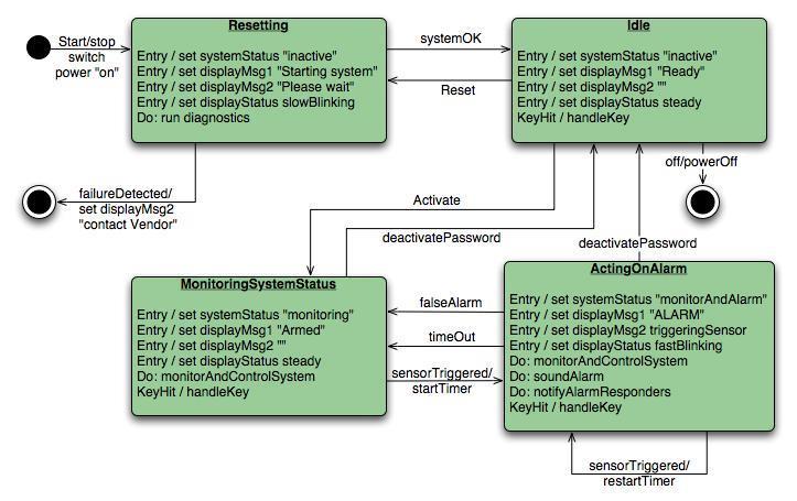
13 Behavioral Element State Diagram Behavioral elements How the system behaves in response to different events (state diagram)
 System accepts input in a variety forms; applies functions to transform it; and produces output in variety")
14 Flow-oriented elements Flow-oriented elements How information is transformed as if flows through the system (data flow diagram) System accepts input in a variety forms; applies functions to transform it; and produces output in variety forms.
15 Data modeling Analysis model often begin with data modeling. Data model consists of three interrelated pieces of information: The data object, The attributes that describe the data object, and The relationships that connect data objects to one another.
16 Data Object A data object is a representation of almost any composite information that must be understood by software. composite information - number of different properties or attributes. A data object can be:- An external entity (e.g., anything that produces or consumes information), A thing (e.g., a report or a display), Event (e.g., an alarm), A role (e.g., salesperson), An organizational unit (e.g., accounting department), A place (e.g., a home), A structure (e.g., a file)
17 For Ex.- Set of attributes can be defined for a person or a car (i.e. Data Object)
18 Data Attributes Define the properties of a data object. Attributes name a data object, describe its characteristics, and in some cases, make reference to another object. In addition, one or more of the attributes must be defined as an identifier( Key value or Unique value). Ex. Data object Car has Id number as identifier.
19 Relationships Data objects are connected to one another in different ways. Consider two data objects Book Bookstore A connection is established between book and bookstore because the two objects are related.

20 Relationship To determine relationship between them, must understand the role of book and bookstore. Can define a set of object/relationship pairs that define the relevant relationships. For Example: A bookstore orders books. A bookstore displays books. A bookstore stocks books. A bookstore sells books. A bookstore returns books.
21 Cardinality and Modality Additional element of data modeling. Object X relates to object Y does not provide enough information. How many occurrences of object X are related to how many occurrences of object Y called cardinality.
22 Cardinality Representing the number of occurrences objects in a given relationship. Cardinality is the specification of the number of occurrences of one [object] that can be related to the number of occurrences of another. Cardinality is usually expressed as simply 'one' or 'many. 1:1 One object can relate to only one other object. 1:M one object can relate to many objects. M:N Some no. of occurrences of an object can relate to some other no. of occurrences of another object.
23 Modality Cardinality does not provide an indication of whether or not a particular data object must participate in the relationship. Modality of a relationship is 0 if there is no explicit need for the relationship to occur or the relationship is optional. The modality is 1 if an occurrences of the relationship is mandatory.
24 Function Modeling & Information Flow Information is transformed as it flows through a computer-based system. The system accepts input in a variety of forms; applies hardware, software, and human elements to transform it; and produces output in a variety of forms Structured analysis began as an information flow modeling technique. A rectangle is used to represent an external entity (software, hardware, a person) A circle (sometimes called a bubble) represents a process or transform that is applied to data (or control) and changes it in some way.
25 Function Modeling & Information Flow An arrow represents one or more data items (data objects) and it should be labeled. The double line represents a data store stored information that is used by the software. First data flow model (sometimes called a level 0 DFD or context diagram) represents the entire system. It provides incremental detail with each subsequent level.
26 Information Flow model
27 Creating a Data Flow Model It enables software engineer to develop models of the information domain and functional domain at the same time. Data flow diagram may be used to represent a system or software at any level of abstraction As DFD is refined into greater levels of detail, the analyst performs an implicit functional decomposition of the system. As DFD refinement results in corresponding refinement of data as it moves through the processes that represent the application
28 DFD Guidelines Depict the system as single bubble in level 0. Primary input and output should be carefully noted Refine by isolating candidate processes and their associated, data objects and data stores All arrows and bubbles should be labeled with meaningful names. Information flow continuity must be maintained from level to level. One bubble at a time should be refined.
29 Data flow models A level 0 DFD, also called a fundamental system model or a context model, represents the entire software element as a single bubble with input and output data indicated by incoming and outgoing arrows. Level 0 DFD refinement into level 1 DFD with all relevant processes to the system. Level 1 DFD each processes can be refined into level 2 DFD. Refinement of DFD continues until each bubble performs a simple function.
30 Control flow model Application which contains collection of classes are dependent on event rather than data, produce control information rather than reports or displays. Such application require the use of control flow modeling in addition to data flow modeling.
31 Guideline for control flow List all processes that are performed by the software. List all the interrupt conditions. List all activities that are performed by operator or actor. List all data conditions. Review all the Control items as possible for control flow inputs / outputs. Describe the behavior of a system by identifying its states; identify how each state is reached; define the transitions between states. Focus on possible omission a very common error in specifying control
32 Control Specification (CSPEC) CSPEC represent the behavior of the system in two different ways. It contains a state diagram sequential specification of behavior. It also contain program activation table combinatorial specification of behavior. By reviewing the state diagram, a software engineer can determine the behavior of the system and can discover whether there are holes in specified behavior. CSPEC describe the behavior of the system, but it gives us no information about the inner working of the processes that activated result.
33
34 Process Specification (PSPEC) Used to describe all flow model processes that appear at the final level of refinement. It include narrative text, a program design language (PDL) description of the process algorithm, mathematical equations, tables, diagrams or charts. By providing a PSPEC to accompany each bubble in the flow model, the software engineer creates a minispec that can serve as guide for design of the software component that will implement the process.
35 Class based modeling Identifying Analysis Classes Specifying Attributes Defining operations CRC modeling
36 Identifying Analysis classes Identify classes by examining the problem statement or by performing a Grammatical Parse on the use-cases or processing narratives developed for the system. How do analysis classes manifest? External entities (other system, people, devices) that produce or consume information Things (reports, display, signals) that are part of the information domain for the problem. Occurrences or events occur within the context of system operations.
37 Analysis classes (cont.) Roles ( manager, engineer, salesperson) played by people who interact with the system. Organizational units (Division, group, team) that are relevant to an application, Places establish the context of the problem and overall function of the system. Structures (sensors, computers) that define a class of objects or related classes of objects.
38 Selecting Criteria - Classes Retained Information Potential class must be remembered so that system can function. Needed Services Must have set of identifiable operations that can change the value of its attributes. Multiple Attributes A class with single attribute may, in fact, be useful during design, but probably better represented as an attributes of another class. Common Attributes These attributes apply to all instances of the class
39 Specifying Attributes Attributes are the set of data objects that fully define the class within the context of the problem. To develop attributes for class, a s/w can study use-case and select those things that reasonably Belong to the class.
40 Defining operations Operations define the behavior of an object. Four broad categories 1. Operations that manipulate data in some way. 2. Operations that perform a computation. 3. Operations that inquire about the state of an object 4. Operations that monitor an object for the occurrence of the controlling event. To derive a set of operations, analyst study a use-case( or narrative) and select those operations that reasonably belongs.
41 Class-Responsibility-collaborator (CRC) modeling A CRC model is a collection of standard index cards that represent classes. Cards are divided into three sections. Top of the cards write class name In the body, list the class responsibility on left. Collaborator on the right Simple means for identifying and organizing the classes that are relevant to system or product. It make use of actual or virtual index cards.
42 CRC modeling Class: Class: Description: Class: Description: Class: FloorPlan Description: Responsibility: Description: Responsibility: Responsibility: Responsibility: defines floor plan name/type manages floor plan positioning Collaborator: Collaborator: Collaborator: Collaborator: scales floor plan for display scales floor plan for display incorporates walls, doors and windows shows position of video cameras Wall Camera
43 CRC Classes Three types classes: 1. Entity Classes (model or business classes):- Represent things that are to be stored in a database and persist throughout the duration of the application. 2. Boundary class:- used to create interface. It designed with the responsibility of managing the way entity objects are represented to users. 3. Controller Class:- manage a unit of work from start to finish. 1. Creation or update of entity objects. 2. Representation of boundary objects as they obtain information from entity objects. 3. Complex communication between sets of objects. 4. Validation of data.
44 Responsibility CRC modeling Guideline for allocating responsibility to classes: 1. System intelligence should be distributed across classes to best address the needs of the problem. 2. Each responsibility should be stated as generally as possible. 3. Information and the behavior related to it should reside within the same class. 4. Information about one thing should be localized with single class, not distributed across multiple classes. 5. Responsibility should be shared among related classes, when appropriate.
45 Collaborations CRC modeling Collaborations represent request from client to server in fulfillment of a client responsibility. Ex. One object collaborate with another object if it needs to send some msg to other object. It identifying relationships between objects. Collaborations are identified by determining whether a class can fulfill each responsibility itself. If it cannot, then it needs to interact with another class.
46 Reviewing CRC model All participants in the review (of the CRC model) are given a subset of the CRC model index cards. Cards that collaborate should be separated (i.e., no reviewer should have two cards that collaborate). All use-case scenarios (and corresponding use-case diagrams) should be organized into categories. The review leader reads the use-case deliberately. As the review leader comes to a named object, she passes a token to the person holding the corresponding class index card.
47 Cont. When the token is passed, the holder of the class card is asked to describe the responsibilities noted on the card. The group determines whether one (or more) of the responsibilities satisfies the use-case requirement. If the responsibilities and collaborations noted on the index cards cannot accommodate the use-case, modifications are made to the cards. This may include the definition of new classes (and corresponding CRC index cards) or the specification of new or revised responsibilities or collaborations on existing cards.
48 Behavioral Modeling Behavioral model indicates how software will respond to external events. To create model Evaluate all use cases to understand the sequence of interaction within the system. Identify events Create sequence for each use-case Build a state diagram for the system. Review the behavioral model to verify accuracy or consistency.
49 Identifying events with the use-cases Use-case represents a sequence of activities that involves actors and the system. An event occurs whenever the system and an actor exchange information. An event is not the information that has been exchanged, but rather the fact that information has been exchanged. An actor should be identified for each event. Information that is exchanged should be noted. Any conditions or constraints should be listed.
50 State Representation 2 diff. characteristics should be considered. Passive State Active State Passive state is simply the current status of all of an object s attributes. Ex. Player class current position and orientation attributes. Active State is current state of the object as it undergoes a continuing transformation or processing. Ex. Player class active state moving, injured, trapped, lost etc. An event must occur to force an object to make a transition from one active state to another.
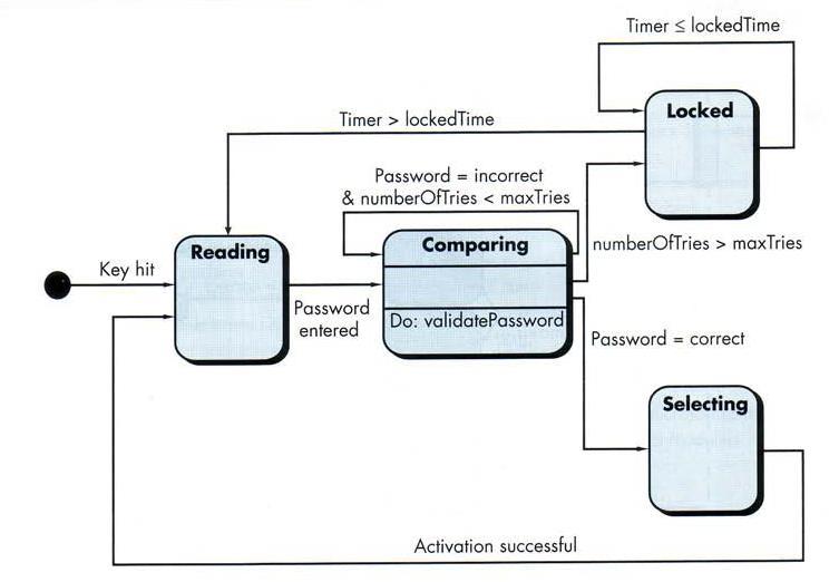
51 State diagram for analysis classes UML state diagram that represents active states for each class and events that causes changes between these active state.
52
53 An action occurs concurrently with the state transition or as a sequence of it and generally involves one or more operations of the object.
54 Sequence diagram It indicates how events cause transitions from object to object. Once event have identified by examining a use-cases, the modeler creates a sequence diagram. It representation of how events cause flow from one objects to another as function of time. Its shorthand version of use-case diagram that represent key classes and the events that cause behavior to flow from class to class. System objects and events will help in creation of effective design.
55 Mechanics of Structured Analysis It all about Entity relationship diagram (ERD) Data flow diagram (DFD) State transition diagram (STD)
56 Data dictionary Data dictionary is an organized listing of all data elements that are relevant to the system, with precise, rigorous definitions so that both user and system analyst will have a common understanding of inputs, outputs, components of stores and [even] intermediate calculations. Data dictionary is always implemented as part of a CASE "structured analysis and design tool. Most contain following information : Name the primary name of the data or control item, the data store or an external entity. Alias other names used for the first entry. Where-used/how-used a listing of the processes that use the data or control item and how it is used (e.g., input to the process, output from the process, as a store, as an external entity.
57 Content description a notation for representing content. Supplementary information other information about data types, preset values (if known), restrictions or limitations, and so forth.
06. Analysis Modeling
 06. Analysis Modeling Division of Computer Science, College of Computing Hanyang University ERICA Campus 1 st Semester 2017 Overview of Analysis Modeling 1 Requirement Analysis 2 Analysis Modeling Approaches
CS485/540 Software Engineering Requirements Modeling (Ch. 6)
") CS485/540 Software Engineering Requirements Modeling (Ch. 6) Cengiz Günay Dept. Math & CS, Emory University Fall 2013 Some slides courtesy of Joan Smith and Roger Pressman Günay (Emory) Requirements Modeling
CS485/540 Software Engineering Requirements Modeling (Ch. 6) Cengiz Günay Dept. Math & CS, Emory University Fall 2013 Some slides courtesy of Joan Smith and Roger Pressman Günay (Emory) Requirements Modeling
Requirements Modeling (Ch. 6)
") Requirements Modeling (Ch. 6) Cengiz Günay CS485/540 Software Engineering Fall 2014 Some slides courtesy of Joan Smith and Roger Pressman Günay (Emory MathCS) Requirements Modeling Fall 2014 1 / 8 (c)
Requirements Modeling (Ch. 6) Cengiz Günay CS485/540 Software Engineering Fall 2014 Some slides courtesy of Joan Smith and Roger Pressman Günay (Emory MathCS) Requirements Modeling Fall 2014 1 / 8 (c)
Introduction to Software Engineering
 Introduction to Software Engineering (CS350) Lecture 07 Jongmoon Baik Requirement Modeling - I Scenarios, Information, and Analysis Classes 2 Requirements Analysis Requirements analysis specifies software
CHAPTER 9 DESIGN ENGINEERING. Overview
 CHAPTER 9 DESIGN ENGINEERING Overview A software design is a meaningful engineering representation of some software product that is to be built. Designers must strive to acquire a repertoire of alternative
Chapter 7 Desain Rekayasa Perangkat Lunak Analysis Modeling. Software Engineering: A Practitioner s Approach by Roger S. Pressman
 Chapter 7 Desain Rekayasa Perangkat Lunak Analysis Modeling Software Engineering: A Practitioner s Approach by Roger S. Pressman Material Scenario-Based Modeling Flow Oriented Modeling Class-Bases Modeling
UNIT-II: Requirements Engineering
 UNIT-II: Requirements Engineering Syllabus a. ELICITING REQUIREMENTS Collaborative Requirements Gathering Quality Function Deployment Usage Scenarios Elicitation Work Products b. BUILDING THE REQUIREMENTS
Modeling. Slides by: Ms. Shree Jaswal. Slides by:ms. Shree Jaswal 1
 Modeling Slides by: Ms. Shree Jaswal Slides by:ms. Shree Jaswal 1 Model What is a model? a model is a simplification of reality Why do we model? we build models so that we can better understand the system
Lab # 1. Structuring System Requirements: Diagrams
 Lab # 1 Structuring System Requirements: Diagrams Objectives 1. Use Case diagrams 2. Class Objects (CO) diagrams 3. Context Data Flow Diagrams (Context DFDs) 4. Level-0 Data Flow Diagrams (Level-0 DFDs)
CS SOFTWARE ENGINEERING QUESTION BANK SIXTEEN MARKS
 DEPARTMENT OF COMPUTER SCIENCE AND ENGINEERING CS 6403 - SOFTWARE ENGINEERING QUESTION BANK SIXTEEN MARKS 1. Explain iterative waterfall and spiral model for software life cycle and various activities
DEPARTMENT OF COMPUTER SCIENCE AND ENGINEERING CS SOFTWARE ENGINEERING
 DEPARTMENT OF COMPUTER SCIENCE AND ENGINEERING CS 6403 - SOFTWARE ENGINEERING QUESTION BANK TWO MARKS UNIT I SOFTWARE PROCESS AND PROJECT MANAGEMENT 1. What is software engineering? Software engineering
Design Concepts and Principles
 Design Concepts and Principles Analysis to Design Data Object Description Entity- Relationship Diagram Data Flow Diagram Process Specification (PSPEC) Component level design (or) procedural design Data
VETRI VINAYAHA COLLEGE OF ENGINEERING AND TECHNOLOGY DEPARTMENT OF COMPUTER SCIENCE AND ENGINEERING
 VETRI VINAYAHA COLLEGE OF ENGINEERING AND TECHNOLOGY DEPARTMENT OF COMPUTER SCIENCE AND ENGINEERING CS6403 SOFTWARE ENGINEERING II year/ IV sem CSE (Regulation 2013) UNIT 1- SOFTWARE PROCESS AND PROJECT
INTRODUCTION TO UNIFIED MODELING MODEL (UML) & DFD. Slides by: Shree Jaswal
 & DFD. Slides by: Shree Jaswal") INTRODUCTION TO UNIFIED MODELING MODEL (UML) & DFD Slides by: Shree Jaswal What is UML? 2 It is a standard graphical language for modeling object oriented software. It was developed in mid 90 s by collaborative
INTRODUCTION TO UNIFIED MODELING MODEL (UML) & DFD Slides by: Shree Jaswal What is UML? 2 It is a standard graphical language for modeling object oriented software. It was developed in mid 90 s by collaborative
Topic # 03. Requirements to Software System: An Overview (Ch. 5 and partially Ch. 6)
") Topic # 03 Requirements to Software System: An Overview (Ch. 5 and partially Ch. 6) 1 Understanding Requirements: An Overview This topic is an overview of Requirements Engineering (RE), and RE is the initial
Topic # 03 Requirements to Software System: An Overview (Ch. 5 and partially Ch. 6) 1 Understanding Requirements: An Overview This topic is an overview of Requirements Engineering (RE), and RE is the initial
Software Engineering Unit 4- Requirement Analysis and Specification
 Software Engineering Unit 4- Requirement Analysis and Specification Requirement Engineering The process to gather the software requirements from client, analyze and document them is known as requirement
SE Assignment III. 1. List and explain primitive symbols used for constructing DFDs. Illustrate the use of these symbols with the help of an example.
 SE Assignment III 1. List and explain primitive symbols used for constructing DFDs. Illustrate the use of these symbols with the help of an example. There are essentially 5 different types of symbols used
Database Principles: Fundamentals of Design, Implementation, and Management Tenth Edition. Chapter 7 Data Modeling with Entity Relationship Diagrams
 Database Principles: Fundamentals of Design, Implementation, and Management Tenth Edition Chapter 7 Data Modeling with Entity Relationship Diagrams Objectives In this chapter, students will learn: The
What s Next. INF 117 Project in Software Engineering. Lecture Notes -Spring Quarter, Michele Rousseau Set 6 System Architecture, UML
 What s Next INF 117 Project in Software Engineering Lecture Notes -Spring Quarter, 2008 Michele Rousseau Set 6 System Architecture, UML Set 6 2 Announcements kreqs should be complete Except minor changes
Functional Design of Web Applications. (partially, Chapter 7)
") Functional Design of Web Applications (partially, Chapter 7) Functional Design: An Overview Users of modern WebApps expect that robust content will be coupled with sophisticated functionality The advanced
Functional Design of Web Applications (partially, Chapter 7) Functional Design: An Overview Users of modern WebApps expect that robust content will be coupled with sophisticated functionality The advanced
Database Systems: Design, Implementation, and Management Tenth Edition. Chapter 4 Entity Relationship (ER) Modeling
 Modeling") Database Systems: Design, Implementation, and Management Tenth Edition Chapter 4 Entity Relationship (ER) Modeling Objectives In this chapter, students will learn: The main characteristics of entity relationship
Database Systems: Design, Implementation, and Management Tenth Edition Chapter 4 Entity Relationship (ER) Modeling Objectives In this chapter, students will learn: The main characteristics of entity relationship
Class-based Modeling. Analysis Classes. Building the Analysis Model 4
 Building the Analysis Model 4 Suradet Jitprapaikulsarn Derived from Roger S. Pressman, Software Engineering: A Practitioner s Approach, 6 th Edition, McGraw-Hill, 2005 Class-based Modeling Identify analysis
Analysis Modeling Week 5
 Analysis Modeling Week 5 Announcement Midterm I Monday March, 7 th Scope Ch. 1, 2, 3, 4 and Ch. 6 of the text book Ch. 1, 2 and 3 of the lab book Analysis modeling dli Agenda (Lecture) Agenda (Lab) Weekly
DATABASE SYSTEMS. Chapter 5 Entity Relationship (ER) Modelling DESIGN IMPLEMENTATION AND MANAGEMENT INTERNATIONAL EDITION ROB CORONEL CROCKETT
 Modelling DESIGN IMPLEMENTATION AND MANAGEMENT INTERNATIONAL EDITION ROB CORONEL CROCKETT") DATABASE SYSTEMS DESIGN IMPLEMENTATION AND MANAGEMENT INTERNATIONAL EDITION ROB CORONEL CROCKETT Chapter 5 Entity Relationship (ER) Modelling 1 Coronel & Crockett 978184480731) In this chapter, you will
DATABASE SYSTEMS DESIGN IMPLEMENTATION AND MANAGEMENT INTERNATIONAL EDITION ROB CORONEL CROCKETT Chapter 5 Entity Relationship (ER) Modelling 1 Coronel & Crockett 978184480731) In this chapter, you will
Darshan Institute of Engineering & Technology for Diploma Studies
 REQUIREMENTS GATHERING AND ANALYSIS The analyst starts requirement gathering activity by collecting all information that could be useful to develop system. In practice it is very difficult to gather all
ASSIGNMENT- I Topic: Functional Modeling, System Design, Object Design. Submitted by, Roll Numbers:-49-70
 ASSIGNMENT- I Topic: Functional Modeling, System Design, Object Design Submitted by, Roll Numbers:-49-70 Functional Models The functional model specifies the results of a computation without specifying
Lecture 5 STRUCTURED ANALYSIS. PB007 So(ware Engineering I Faculty of Informa:cs, Masaryk University Fall Bühnová, Sochor, Ráček
 Lecture 5 STRUCTURED ANALYSIS PB007 So(ware Engineering I Faculty of Informa:cs, Masaryk University Fall 2015 1 Outline ² Yourdon Modern Structured Analysis (YMSA) Context diagram (CD) Data flow diagram
copyright 1996, 2001, 2005 R.S. Pressman & Associates, Inc.
 Software Engineering: A Practitioner s Approach, 6/e Chapter 10 Architectural Design copyright 1996, 2001, 2005 R.S. Pressman & Associates, Inc. For University Use Only May be reproduced ONLY for student
Introduction to UML What is UML? Motivations for UML Types of UML diagrams UML syntax Descriptions of the various diagram types Rational Rose (IBM.. M
 Introduction to UML Part I 1 What is UML? Unified Modeling Language, a standard language for designing and documenting a system in an object- oriented manner. It s a language by which technical architects
Software Life-Cycle Models
 Software Life-Cycle Models CMPSC 487 Lecture 03 Topics: UML Class Diagram Rosenburg Chap 2. Domain Modeling A. UML: Unified Modeling Language UML is a general-purpose, developmental, modeling language
Chapter 10. Object-Oriented Analysis and Modeling Using the UML. McGraw-Hill/Irwin
 Chapter 10 Object-Oriented Analysis and Modeling Using the UML McGraw-Hill/Irwin Copyright 2007 by The McGraw-Hill Companies, Inc. All rights reserved. Objectives 10-2 Define object modeling and explain
Chapter 4. In this chapter, you will learn:
 Chapter Entity Relationship (ER) Modeling Database Systems: Design, Implementation, and Management, Seventh Edition, Rob and Coronel 1 In this chapter, you will learn: The main characteristics of entity
Software Development Methodologies
 Software Development Methodologies Lecturer: Raman Ramsin Lecture 3 Seminal Object-Oriented Methodologies: A Feature-Focused Review 1 Responsibility-Driven Design (RDD) Introduced in 1990; a UML-based
Meltem Özturan
 Meltem Özturan www.mis.boun.edu.tr/ozturan/samd 1 2 Modeling System Requirements Object Oriented Approach to Requirements OOA considers an IS as a set of objects that work together to carry out the function.
R.S. Pressman & Associates, Inc. For University Use Only
 Software Engineering: A Practitioner s Approach, 6/e Chapter 10 Architectural Design copyright 1996, 2001, 2005 R.S. Pressman & Associates, Inc. For University Use Only May be reproduced ONLY for student
Object-Oriented Design and Modeling Using the UML
 Design Classes Object-Oriented Design and Modeling Using the UML Based on Chapter 18 of Whitten, Bentley, and Dittman: Systems Analysis and Design for the Global Enterprise (7th Ed). McGraw Hill. 2007
System Models. Minsoo Ryu. Hanyang University. Real-Time Computing and Communications Lab., Hanyang University
 System Models Minsoo Ryu Hanyang University 1. Context Models 2. Structural Model 3. Behavioural Models 4. Object Models Contents 2 2 Building a System Model User requirements should be written in natural
A l Ain University Of Science and Technology
 A l Ain University Of Science and Technology 4 Handout(4) Database Management Principles and Applications The Entity Relationship (ER) Model http://alainauh.webs.com/ 1 In this chapter, you will learn:
Introduction to Software Specifications and Data Flow Diagrams. Neelam Gupta The University of Arizona
 Introduction to Software Specifications and Data Flow Diagrams Neelam Gupta The University of Arizona Specification A broad term that means definition Used at different stages of software development for
Objectives. Explain the purpose and objectives of objectoriented. Develop design class diagrams
 Objectives Explain the purpose and objectives of objectoriented design Develop design class diagrams Develop interaction diagrams based on the principles of object responsibility and use case controllers
Hippo Software BPMN and UML Training
 Hippo Software BPMN and UML Training Icon Key: www.hippo-software.co.uk Teaches theory concepts and notation Teaches practical use of Enterprise Architect Covers BPMN, UML, SysML, ArchiMate Includes paper
Object-Oriented Systems Analysis and Design Using UML
 10 Object-Oriented Systems Analysis and Design Using UML Systems Analysis and Design, 8e Kendall & Kendall Copyright 2011 Pearson Education, Inc. Publishing as Prentice Hall Learning Objectives Understand
Slides copyright 1996, 2001, 2005, 2009 by Roger S. Pressman. For non-profit educational use only
 Chapter 11 Requirements Modeling: Behavior, Patterns, and Web/Mobile Apps Slide Set to accompany Software Engineering: A Practitioner s Approach, 8/e by Roger S. Pressman Slides copyright 1996, 2001, 2005,
MIGRATING COOL:TEAMWORK MODELS INTO MODERN CASE TOOLS
 MIGRATING COOL:TEAMWORK MODELS INTO MODERN CASE TOOLS A UML/MOF METAMODEL FOR HATLEY-PIRBHAI SYSTEM SPECIFICATION By Colin Coates (Senior Consultant) Version 1.0 Tuesday, 13 October 2015 Table of Contents
ArchiMate 2.0. Structural Concepts Behavioral Concepts Informational Concepts. Business. Application. Technology
 ArchiMate Core Structural Concepts Behavioral Concepts Informational Concepts interaction Technology Application Layer Concept Description Notation Concept Description Notation Actor An organizational
System Analysis & design
 Assiut University Faculty of Computers and Information System Analysis & design Year 2 Academic Year 2014/ 2015 Term (2) Copyright 2014 Dr. Hossam Ragab 6 data model describes the data that flow through
UNIT 1-SOFTWARE PROCESS AND PROJECT MANAGEMENT
 PART A (2 MARKS) UNIT 1-SOFTWARE PROCESS AND PROJECT MANAGEMENT 1. What is software engineering? Software engineering is a discipline in which theories, methods and tools are applied to develop professional
Software Modeling & Analysis. - Introduction to SASD - Structured Analysis. Lecturer: JUNBEOM YOO
 Software Modeling & Analysis - Introduction to SASD - Structured Analysis Lecturer: JUNBEOM YOO jbyoo@konkuk.ac.kr References Modern Structured Analysis, Edward Yourdon, 1989. Introduction to System Analysis
NOTES ON OBJECT-ORIENTED MODELING AND DESIGN
 NOTES ON OBJECT-ORIENTED MODELING AND DESIGN Stephen W. Clyde Brigham Young University Provo, UT 86402 Abstract: A review of the Object Modeling Technique (OMT) is presented. OMT is an object-oriented
Structured Analysis and Structured Design
 Structured Analysis and Structured Design - Introduction to SASD - Structured Analysis - Structured Design Ver. 1.5 Lecturer: JUNBEOM YOO jbyoo@konkuk.ac.kr http://dslab.konkuk.ac.kr References Modern
Database Systems: Design, Implementation, and Management Tenth Edition. Chapter 4 Entity Relationship (ER) Modeling
 Modeling") Database Systems: Design, Implementation, and Management Tenth Edition Chapter 4 Entity Relationship (ER) Modeling 4.1 The Entity Relationship Model (ERM) ER model forms the basis of an ER diagram ERD
Database Systems: Design, Implementation, and Management Tenth Edition Chapter 4 Entity Relationship (ER) Modeling 4.1 The Entity Relationship Model (ERM) ER model forms the basis of an ER diagram ERD
Lecture c, Process Mapping: Yourdon Notation for Data Flow Diagrams, covers Yourdon notation for data flow diagrams.
 WORKFLOW ANALYSIS Audio Transcript Component 10 Unit 3 Lecture C Fundamentals of Health Workflow Process Analysis & Redesign Interpreting and Creating Process Diagrams Process Mapping Yourdon Notation
Unified Modeling Language (UML)
") Appendix H Unified Modeling Language (UML) Preview The Unified Modeling Language (UML) is an object-oriented modeling language sponsored by the Object Management Group (OMG) and published as a standard
Appendix H Unified Modeling Language (UML) Preview The Unified Modeling Language (UML) is an object-oriented modeling language sponsored by the Object Management Group (OMG) and published as a standard
A l Ain University Of Science and Technology
 A l Ain University Of Science and Technology 4 Handout(4) Database Management Principles and Applications The Entity Relationship (ER) Model http://alainauh.webs.com/ http://www.comp.nus.edu.sg/~lingt
Ali Khan < Project Name > Design Document. Version 1.0. Group Id: S1. Supervisor Name: Sir.
 < Project Name > Design Document Version 1.0 Group Id: S1. Supervisor Name: Sir. Revision History Date Version Description Author Table of Contents 1. Introduction of Design Document 2. Entity Relationship
Activities Radovan Cervenka
 Unified Modeling Language Activities Radovan Cervenka Activity Model Specification of an algorithmic behavior. Used to represent control flow and object flow models. Executing activity (of on object) is
MechEng SE3 Lecture 7 Domain Modelling
 MechEng SE3 Lecture 7 Domain Modelling Simon Gay (slides by Phil Gray) 17 February 2010 1 This week s supplementary reading Zero Balances and Zero Responsibility Michael Bolton http://www.developsense.com/essays/zero.html
MULTIPLE CHOICE. Choose the one alternative that best completes the statement or answers the question.
 Exam Name MULTIPLE CHOICE. Choose the one alternative that best completes the statement or answers the question. 1) A process has a: 1) A) pronoun label B) noun phrase label C) verb phrase label D) adjective
Introduction to Software Engineering
 Introduction to Software Engineering (CS350) Lecture 08 Jongmoon Baik Requirement Modeling - II Flow, Behavior, Patterns, and Webapps 2 Requirements Modeling Strategies structured analysis considers data
Entity Relationship Modelling
 Entity Relationship Modelling Overview Database Analysis Life Cycle Components of an Entity Relationship Diagram What is a relationship? Entities, attributes, and relationships in a system The degree of
Design Concepts. Slide Set to accompany. Software Engineering: A Practitioner s Approach, 7/e by Roger S. Pressman
 Chapter 8 Design Concepts Slide Set to accompany Software Engineering: A Practitioner s Approach, 7/e by Roger S. Pressman Slides copyright 1996, 2001, 2005, 2009 by Roger S. Pressman For non-profit educational
Lecture 8: Chapter 8!
 Lecture 8: Chapter 8! Design Concepts! Slide Set to accompany Software Engineering: A Practitioner s Approach, 7/e " by Roger S. Pressman Slides copyright 1996, 2001, 2005, 2009 by Roger S. Pressman For
Darshan Institute of Engineering & Technology for Diploma Studies Rajkot Unit-1
 Failure Rate Darshan Institute of Engineering & Technology for Diploma Studies Rajkot Unit-1 SOFTWARE (What is Software? Explain characteristics of Software. OR How the software product is differing than
Presenter: Dong hyun Park
 Presenter: 200412325 Dong hyun Park Design as a life cycle activity bonds the requirements to construction Process of breaking down the system into components, defining interfaces and defining components
History of object-oriented approaches
 Prof. Dr. Nizamettin AYDIN naydin@yildiz.edu.tr http://www.yildiz.edu.tr/~naydin Object-Oriented Oriented Systems Analysis and Design with the UML Objectives: Understand the basic characteristics of object-oriented
Progress Report. Object-Oriented Software Development: Requirements elicitation (ch. 4) and analysis (ch. 5) Object-oriented software development
 and analysis (ch. 5) Object-oriented software development") Progress Report Object-Oriented Software Development: Requirements elicitation (ch. 4) and analysis (ch. 5) CS 4354 Summer II 2014 Jill Seaman So far we have learned about the tools used in object-oriented
Progress Report Object-Oriented Software Development: Requirements elicitation (ch. 4) and analysis (ch. 5) CS 4354 Summer II 2014 Jill Seaman So far we have learned about the tools used in object-oriented
Chapter 6 Structuring System Requirements: Process Modeling 6.1
 Chapter 6 Structuring System Requirements: Process Modeling 6.1 Learning Objectives Explain process modeling Discuss data-flow diagramming mechanics, definitions, and rules Discuss balancing data-flow
Software Engineering. Page 1. Objectives. Object-Behavioural Modelling. Analysis = Process + Models. Case Study: Event Identification
 Software Engineering Object-Oriented Analysis (State and Interaction Diagrams) James Gain (jgain@cs.uct.ac.za) http://people.cs.uct.ac.za/~jgain 1. Show the object-behaviour design process Objectives 2.
Oracle Data Modeling and Relational Database Design
 Oracle University Contact Us: +632 976 8896, 1800 16516277 Oracle Data Modeling and Relational Database Design Duration: 4 Days What you will learn This Oracle Data Modeling and Relational Database Design
CS 451 Software Engineering
 CS 451 Software Engineering Yuanfang Cai Room 104, University Crossings 215.895.0298 yfcai@cs.drexel.edu 1 Elaboration 2 Elaboration: Building the Analysis Model An analysis model provides a description
UML Fundamental. OutLine. NetFusion Tech. Co., Ltd. Jack Lee. Use-case diagram Class diagram Sequence diagram
 UML Fundamental NetFusion Tech. Co., Ltd. Jack Lee 2008/4/7 1 Use-case diagram Class diagram Sequence diagram OutLine Communication diagram State machine Activity diagram 2 1 What is UML? Unified Modeling
Content Management for the Defense Intelligence Enterprise
 Gilbane Beacon Guidance on Content Strategies, Practices and Technologies Content Management for the Defense Intelligence Enterprise How XML and the Digital Production Process Transform Information Sharing
UNIT III. Software Design
 UNIT III Software Design Design Specification Models Data design - created by transforming the analysis information model (data dictionary and ERD) into data structures required to implement the software
Unit 1 Introduction to Software Engineering
 Unit 1 Introduction to Software Engineering João M. Fernandes Universidade do Minho Portugal Contents 1. Software Engineering 2. Software Requirements 3. Software Design 2/50 Software Engineering Engineering
Elevator Control System
 Control System Koichiro Ochimizu School of Information Science Japan Advanced Institute of Science and Technology Schedule(3/3) March 2 3:00 Unified Process and COMET 4:30 Case Study of Control System
Information Technology Audit & Cyber Security
 Information Technology Audit & Cyber Security Structured Data Requirements Systems & Infrastructure Lifecycle Management with E-R LEARNING OBJECTIVES Explain the role of conceptual data modeling in the
Slides copyright 1996, 2001, 2005, 2009 by Roger S. Pressman
 Chapter 7 Requirements Modeling: Flow, Behavior, Patterns, and WebApps Slides in this presentation were taken from two sources: Software Engineering: A Practitioner s Approach, 7/e by Roger S. Pressman
1. i. What are the 3 major components of a information system and show their relationship input output
 Higher National Diploma in Information Technology First Year, Second semesterexamination-2011 IT2005: System Analysis and Design Answer Script No. of pages: 11 1. i. What are the 3 major components of
Slide 1 Welcome to Fundamentals of Health Workflow Process Analysis and Redesign: Process Mapping: Entity-Relationship Diagrams. This is Lecture e.
 WORKFLOW ANALYSIS Audio Transcript Component 10 Unit 3 Lecture E Fundamentals of Health Workflow Process Analysis & Redesign Interpreting and Creating Process Diagrams Process Mapping UML notation for
Topics. Overview- The UML Functional Model. Structural Model. Behavioral Models. Use Case Diagram (essential and system)
") Topics Overview- The UML Functional Model Use Case Diagram (essential and system) Structural Model Class/object, Component and Deployment Diagram Behavioral Models Activity, State chart, sequence /collaboration
Topics Overview- The UML Functional Model Use Case Diagram (essential and system) Structural Model Class/object, Component and Deployment Diagram Behavioral Models Activity, State chart, sequence /collaboration
Chapter 5: Structural Modeling
 Chapter 5: Structural Modeling Objectives Understand the rules and style guidelines for creating CRC cards, class diagrams, and object diagrams. Understand the processes used to create CRC cards, class
Introduction to Software Engineering
 Introduction to Software Engineering Gérald Monard Ecole GDR CORREL - April 16, 2013 www.monard.info Bibliography Software Engineering, 9th ed. (I. Sommerville, 2010, Pearson) Conduite de projets informatiques,
Data Analysis 1. Chapter 2.1 V3.1. Napier University Dr Gordon Russell
 Data Analysis 1 Chapter 2.1 V3.1 Copyright @ Napier University Dr Gordon Russell Entity Relationship Modelling Overview Database Analysis Life Cycle Components of an Entity Relationship Diagram What is
Database Principles: Fundamentals of Design, Implementation, and Management Tenth Edition. Chapter 8 Data Modeling Advanced Concepts
 Database Principles: Fundamentals of Design, Implementation, and Management Tenth Edition Chapter 8 Data Modeling Advanced Concepts Objectives In this chapter, students will learn: About the extended entity
Modern Systems Analysis and Design Seventh Edition
 Modern Systems Analysis and Design Seventh Edition Jeffrey A. Hoffer Joey F. George Joseph S. Valacich Structuring System Data Requirements Learning Objectives ü Concisely define each of the following
Chapter 4 Entity Relationship Modeling In this chapter, you will learn:
 Chapter Entity Relationship Modeling In this chapter, you will learn: What a conceptual model is and what its purpose is The difference between internal and external models How internal and external models
Modeling with UML. (1) Use Case Diagram. (2) Class Diagram. (3) Interaction Diagram. (4) State Diagram
 Use Case Diagram. (2) Class Diagram. (3) Interaction Diagram. (4) State Diagram") Modeling with UML A language or notation intended for analyzing, describing and documenting all aspects of the object-oriented software system. UML uses graphical notations to express the design of software
Modeling with UML A language or notation intended for analyzing, describing and documenting all aspects of the object-oriented software system. UML uses graphical notations to express the design of software
Architectural Blueprint
 IMPORTANT NOTICE TO STUDENTS These slides are NOT to be used as a replacement for student notes. These slides are sometimes vague and incomplete on purpose to spark a class discussion Architectural Blueprint
Requirements Modeling: Flow, Behavior, Patterns, and Webapps (Ch. 7)
") Requirements Modeling: Flow, Behavior, Patterns, and Webapps (Ch. 7) Cengiz Günay CS485/540 Software Engineering Fall 2014, Some slides courtesy of Joan Smith, Roger Pressman, and the Internets Günay (Emory
Requirements Modeling: Flow, Behavior, Patterns, and Webapps (Ch. 7) Cengiz Günay CS485/540 Software Engineering Fall 2014, Some slides courtesy of Joan Smith, Roger Pressman, and the Internets Günay (Emory
Ch 4: Requirements Engineering. What are requirements?
 Ch 4: Engineering What are? Functional and non-functional The software document specification engineering processes elicitation and analysis validation management The descriptions of what the system should
Module 5. Function-Oriented Software Design. Version 2 CSE IIT, Kharagpur
 Module 5 Function-Oriented Software Design Lesson 12 Structured Design Specific Instructional Objectives At the end of this lesson the student will be able to: Identify the aim of structured design. Explain
WHAT IS SOFTWARE ARCHITECTURE?
 WHAT IS SOFTWARE ARCHITECTURE? Chapter Outline What Software Architecture Is and What It Isn t Architectural Structures and Views Architectural Patterns What Makes a Good Architecture? Summary 1 What is
13/11/2017. Meltem Özturan misprivate.boun.edu.tr/ozturan/mis515
 Meltem Özturan misprivate.boun.edu.tr/ozturan/mis515 2 1 Traditional Approach to Requirements Data Flow Diagram (DFD) A graphical system model that shows all of the main requirements for an information
CS6403 SOFTWARE ENGINEERING Year / Sem : II / IV Sub. Code &Subject : CS6403 SOFTWARE ENGINEERING QUESTION BANKWITH ANSWERS
 CS6403 SOFTWARE ENGINEERING Year / Sem : II / IV Sub. Code &Subject : CS6403 SOFTWARE ENGINEERING QUESTION BANKWITH ANSWERS UNIT 1-SOFTWARE PROCESS AND PROJECT MANAGEMENT 1. What is software engineering?
UNIT III DESIGN CONCEPTS AND PRINCIPLES
 UNIT III DESIGN CONCEPTS AND PRINCIPLES Design process and concepts modular design design heuristic design model and document. Architectural design software architecture data design architectural design
Chapter 5 Practice: A Generic View
 Chapter 5 Practice: A Generic View Moonzoo Kim CS Division of EECS Dept. KAIST moonzoo@cs.kaist.ac.kr http://pswlab.kaist.ac.kr/courses/cs550-07 Spring 2007 1 What is Practice? Practice is a broad array
CHAPTER 19: Building a Preliminary Behavioral Model
 1 z 7 CHAPTER 19: Building a Preliminary Behavioral Model Things are always at their best in their beginning. Blaise Pascal Lettres Provinciales, 1656-1657, no. 4 IN THIS CHAPTER, YOU WILL LEARN: Why a
OBJECT ORIENTED DESIGN with the Unified Process. Use Case Realization
 OBJECT ORIENTED DESIGN with the Unified Process Use Case Realization Objectives Explain the purpose and objectives of objectoriented design Develop design class diagrams Develop detailed sequence diagrams
Component-Level Design. Slides copyright 1996, 2001, 2005, 2009 by Roger S. Pressman. For non-profit educational use only
 Chapter 10 Component-Level Design Slide Set to accompany Software Engineering: A Practitioner s Approach, 7/e by Roger S. Pressman Slides copyright 1996, 2001, 2005, 2009 by Roger S. Pressman For non-profit
SE 1: Software Requirements Specification and Analysis
 SE 1: Software Requirements Specification and Analysis Lecture 9: UML Class (Concept), Object, Communication Diagrams Nancy Day, Davor Svetinović http://www.student.cs.uwaterloo.ca/ cs445/winter2006 uw.cs.cs445