The Monte Carlo analysis can vary basic components and models - subcircuit data is not varied during the analysis.
|
|
|
- Sherilyn Griffin
- 6 years ago
- Views:
Transcription

1 Monte Carlo Analysis Old Content - visit altium.com/documentation Modified by Phil Loughhead on 4-Mar-2014 Description Monte Carlo analysis allows you to perform multiple simulation runs with component values randomly varied across specified tolerances. The Simulator performs multiple passes of any of the standard analyses that are enabled (AC, DC Sweep, Operating Point, Transient, Transfer Function, Noise). The Monte Carlo analysis can vary basic components and models - subcircuit data is not varied during the analysis. Setup Monte Carlo analysis is set up on the Monte Carlo Analysis Setup page of the Analyses Setup dialog (after the dialog appears, click the Monte Carlo Analysis entry in the Analyses/Options list). An example setup for this analysis type is shown in the image below: Parameters Seed - this value is used by the Simulator to generate random numbers for the various runs of the analysis. If you want to run a simulation with a different series of random numbers, this value must be changed to another number. (Default = -1). Distribution - this parameter defines the distribution of values obtained during random number generation. Three distribution types are available: Uniform (Default)
2 This is a flat distribution. Values are uniformly distributed over the specified tolerance range. For example, for a 1K resistor with a tolerance of 10%, there is an equal chance of the randomly generated value being anywhere between 900Ω and 1100Ω. Gaussian Values are distributed according to a Gaussian (bell-shaped) curve, with the center at the nominal value and the specified tolerance at +/- 3 standard deviations. For a resistor with a value of 1K +/- 10%, the center of the distribution would be at 1000Ω, +3 standard deviations is 1100Ω and -3 standard deviations is 990Ω. With this type of distribution, there is a higher probability that the randomly generated value will be closer to the specified value. Worst Case This is the same as the Uniform distribution, but only the end points (worst case) of the range are used. For a 1K +/- 10% resistor, the value used would be randomly chosen from the two worst case values of 990Ω and 1100Ω. On any one simulation run there is an equal chance that the high-end worst case value (1100 Ω) or low-end worst case value (990 Ω) will be used. Number of Runs - the number of simulation runs you want the Simulator to perform. Different device values will be used for each run, within the specified tolerance range. (Default = 5). Default Resistor Tolerance - the default tolerance to be observed for resistors. The value is entered as a percentage (Default = 10%). Default Capacitor Tolerance - the default tolerance to be observed for capacitors. The value is entered as a percentage (Default = 10%). Default Inductor Tolerance - the default tolerance to be observed for inductors. The value is entered as a percentage (Default = 10%). Default Transistor Tolerance - the default tolerance to be observed for transistors (beta forward). The value is entered as a percentage (Default = 10%). Default DC Source Tolerance - the default tolerance to be observed for DC Sources. The value is entered as a percentage (Default = 10%). Default Digital Tp Tolerance - the default tolerance to be observed for Digital Tp (propagation delay for digital devices). The value is entered as a percentage (Default = 10%). The tolerance is used to determine the allowable range of values that can be generated by the random number generator for a device. For a device with nominal value Val Nom, the range can be expressed as: ValNom - (Tolerance * ValNom) RANGE ValNom + (Tolerance * ValNom) Specific Tolerances - this parameter shows how many specific tolerances are currently defined. These are user-defined tolerances that are applied to specific components in the circuit. You can set up your own specific tolerances as required, by clicking the... button to the right of the field. The Monte Carlo - Specific Tolerances dialog will appear. Specific tolerances that are defined will override the default tolerance settings. (Default = 0 defined). Defining Specific Tolerances To define a new specific tolerance, click the Add button at the bottom of the Monte Carlo - Specific Tolerances dialog. A new row will be added, as shown in the image below:

3 In the Designator field, choose the component that the specific tolerance is to apply to, from the drop-down list. Include a parameter in the Parameter field if the device requires it. Supported parameters include: the propagation delay of a digital component, the Beta forward of a transistor and the resistance of a potentiometer. Each component can have two tolerances set: a Device tolerance and a Lot tolerance. Both device and lot tolerances are allowed, but only one is required. For a specific component, device and lot tolerances are calculated independently (using different random numbers) and then added together. Set the Tolerance field to give the percentage tolerance for the component. The Tracking No. field is used to assign a common tracking number to components when you require the variation in their tolerance to be correlated. The Distribution field is used to specify the distribution type used for random number generation (Uniform, Gaussian or Worst Case). If you give two components the same tracking number and device distribution then the same random number is used for both components when the device values for a simulation run are calculated. Combined device and lot tolerances are useful where values are not completely correlated, but are not completely independent either. An example would be two different resistor packs. Here, the lot tolerance can be large (that is, the variation from wafer to wafer), while the device tolerance (the variation from resistor to resistor in the same package), is small. In this case the device tolerance should not be ignored because it may limit the overall performance of a circuit. Consider the following example: Assume R1 and R2 are both 1K, with a Device Tolerance of 1% (same Device Tracking number) and they have a Lot Tolerance of 4%, with the same Lot Tracking number.
. However, during the same run the values of each resistor cannot be any farther than +/- 1% from their nominal value, or 2% from each other.")
4 For each Monte Carlo run the resistors are first assigned the same lot variation (a nominal value) between +/- 4%. Then each resistor is assigned a device tolerance between +/- 1%. This gives a total tolerance of 5% (1% + 4%). However, during the same run the values of each resistor cannot be any farther than +/- 1% from their nominal value, or 2% from each other. Notes At least one of the standard analysis types (AC, DC Sweep, Operating Point, Transient, Transfer Function, Noise) must be enabled in order to perform a Monte Carlo analysis. Data is saved for all signals in the Available Signals list, on the General Setup page of the Analyses Setup dialog. Running a Monte Carlo analysis can result in a large amount of data being calculated. To limit the amount of data calculated, you can set the Collect Data For option on the General Setup page of the Analyses Setup dialog to Active Signals. With this option, data is only calculated for variables currently listed in the Active Signals list. Each component is randomly varied independent of other components. For example, if a circuit has two 10 K resistors, and the default tolerance is set to 10%, then during the first pass of the simulation, one resistor might have a value of 953 Ω, and the other one could be 1022 Ω. The program uses a separate and independent random number to generate the value for each component. As running a Monte Carlo analysis actually performs multiple passes of the enabled standard analyses, there is a special identifier used when displaying the waveforms in the Sim Data Editor's Waveform Analysis window. Each pass is identified by adding a letter and number as a suffix to the waveform name. For a Monte Carlo analysis, the letter used is m and the number used identifies which pass the waveform relates to (e.g. Output_m1, Output_m2, etc). Examples
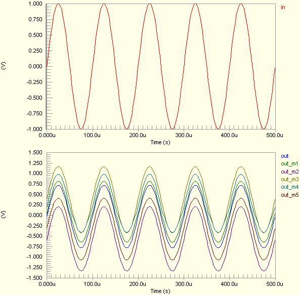
5 Consider the circuit in the image above, where a Transient analysis is to be performed in conjunction with the use of the Monte Carlo analysis feature. The Transient analysis is defined with the following parameter values: Transient Start Time = Transient Stop Time = 500.0u Transient Step Time = 2.000u Transient Max Step Time = 2.000u The Monte Carlo analysis is defined with the following parameter values: Seed = -1 Distribution = Uniform Number of Runs = 5 Default Resistor Tolerance = 15% Default Capacitor Tolerance = 15% All other parameters are left at their default values. The entry in the SPICE netlist will be:
6 *Selected Circuit Analyses:.TRAN 2E E-6.CONTROL TOL C1 DEV=15% Uniform TOL Q1[BF] DEV=10% Uniform TOL Q2[BF] DEV=10% Uniform TOL R1 DEV=15% Uniform TOL R2 DEV=15% Uniform TOL R3 DEV=15% Uniform TOL R4 DEV=15% Uniform TOL RL DEV=15% Uniform TOL V1 DEV=10% Uniform TOL VCC DEV=10% Uniform TOL VSS DEV=10% Uniform MC 5 SEED=-1.ENDC unning the simulation will yield standard waveforms for the IN and OUT signals. For the OUT signal, the following additional waveforms will be available in the Source Data region of the Sim Data panel, corresponding to the five runs performed as part of the Monte Carlo analysis. out_m1 out_m2 out_m3 out_m4 out_m5 Simply make the wave plot containing the out signal active and double-click on each additional waveform to add it to the view. The default waveform (out) will also be generated for comparison.
7 Source URL:
Parameter Sweep. Description. Setup. Parameters. Modified by on 13-Sep-2017
 Parameter Sweep Old Content - visit altium.com/documentation Modified by on 13-Sep-2017 Description The Parameter Sweep feature allows you to sweep the value of a device in defined increments, over a specified
Getting started. Starting Capture. To start Capture. This chapter describes how to start OrCAD Capture.
 Getting started 1 This chapter describes how to start OrCAD Capture. Starting Capture The OrCAD Release 9 installation process puts Capture in the \PROGRAM FILES\ORCAD\CAPTURE folder, and adds Pspice Student
Lesson 2: DC Bias Point Analysis
 2 Lesson 2: DC Bias Point Analysis Lesson Objectives After you complete this lesson you will be able to: Create a simulation profile for DC Bias analysis Netlist the design for simulation Run a DC Bias
Copyright 2008 Linear Technology. All rights reserved. Getting Started
 Copyright. All rights reserved. Getting Started Copyright. All rights reserved. Draft a Design Using the Schematic Editor 14 Start with a New Schematic New Schematic Left click on the New Schematic symbol
TUTORIAL How to Use the SPICE Module
 TUTORIAL How to Use the SPICE Module February 2018 1 1. Overview The SPICE Module is an add-on option in PSIM. Powered by CoolSPICE developed by CoolCAD Electronics LLC., the SPICE Module provides a SPICE
TUTORIAL How to Use the SPICE Module
 TUTORIAL How to Use the SPICE Module November 2017 1 1. Overview The SPICE Module is an add-on option in PSIM. Powered by CoolSPICE developed by CoolCAD Electronics LLC., the SPICE Module provides a SPICE
PSpice Tutorial. Physics 160 Spring 2006
 PSpice Tutorial This is a tutorial designed to guide you through the simulation assignment included in the first homework set. You may either use the program as installed in the lab, or you may install
ESE 570 Cadence Lab Assignment 2: Introduction to Spectre, Manual Layout Drawing and Post Layout Simulation (PLS)
") ESE 570 Cadence Lab Assignment 2: Introduction to Spectre, Manual Layout Drawing and Post Layout Simulation (PLS) Objective Part A: To become acquainted with Spectre (or HSpice) by simulating an inverter,
ESE 570 Cadence Lab Assignment 2: Introduction to Spectre, Manual Layout Drawing and Post Layout Simulation (PLS) Objective Part A: To become acquainted with Spectre (or HSpice) by simulating an inverter,
Using SIMetrix/SIMPLIS in Altium Designer
 Using SIMetrix SIMPLIS Circuit Simulation Old Content - visit altium.com/documentation Modified by on 13-Sep-2017 Catena Software's SIMetrix/SIMPLIS is a popular Circuit Simulation package. SIMetrix/SIMPLIS
Simulation examples Chapter overview
 Simulation examples 2 Chapter overview The examples in this chapter provide an introduction to the methods and tools for creating circuit designs, running simulations, and analyzing simulation results.
Manual for Wavenology EM Graphic Circuit Editor. Wave Computation Technologies, Inc. Jan., 2013
 Manual for Wavenology EM Graphic Circuit Editor Wave Computation Technologies, Inc. Jan., 2013 1 Introduction WCT Graphic Circuit Editor is used to build a Spice circuit model in WCT EM full wave simulator.
TUTORIAL 1. V1.1 Update on Sept 17, 2003 ECE 755. Part 1: Design Architect IC
 TUTORIAL 1 V1.1 Update on Sept 17, 2003 ECE 755 Part 1: Design Architect IC DA-IC provides a design environment comprising tools to create schematics, symbols and run simulations. The schematic editor
Setting up an initial ".tcshrc" file
 ECE445 Fall 2005 Introduction to SaberSketch The SABER simulator is a tool for computer simulation of analog systems, digital systems and mixed signal systems. SaberDesigner consists of the three tools,
MENTOR GRAPHICS IC DESIGN MANUAL. Schematic & Simulation. Gun Jun K Praveen Jayakar Thomas Zheng Huan Qun
 MENTOR GRAPHICS IC DESIGN MANUAL Schematic & Simulation By Gun Jun K Praveen Jayakar Thomas Zheng Huan Qun August 2004 Signal Processing & VLSI Design Laboratory Department of Electrical & Computer Engineering
PSpice Analog and mixed signal simulation
 PSpice Analog and mixed signal simulation You can count on PSpice for accurate circuit simulation results and regular innovations. PSpice has been tried and proven by thousands of engineers. Since the
Click on the SwCAD III shortcut created by the software installation.
 LTSpice Guide Click on the SwCAD III shortcut created by the software installation. Select File and New Schematic. Add a component Add a resistor Press R or click the resistor button to insert a resistor.
METAL OXIDE VARISTORS
 POWERCET CORPORATION METAL OXIDE VARISTORS PROTECTIVE LEVELS, CURRENT AND ENERGY RATINGS OF PARALLEL VARISTORS PREPARED FOR EFI ELECTRONICS CORPORATION SALT LAKE CITY, UTAH METAL OXIDE VARISTORS PROTECTIVE
Analog IC Simulation. Mentor Graphics 2006
 Analog IC Simulation Mentor Graphics 2006 Santa Clara University Department of Electrical Engineering Date of Last Revision: March 29, 2007 Table of Contents 1. Objective... 3 2. Basic Test Circuit Creation...
Spayn Worst-Case Modeling
 Presentation Outline Motivation Requirements for Accurate Worst-Case Modeling Traditional Approach to Worst-Case Modeling PCA or PFA Approach Worst-Case Design Techniques Employing PCA or PFA Worst-Case
Cadence simulation technology for PCB design
 DATASHEET CADENCE SIMULATION FOR PCB DESIGN On larger designs especially, PCB design teams need fast and reliable simulation to achieve convergence. Cadence simulation technology for PCB design offers
Risk Assessment of a LM117 Voltage Regulator Circuit Design Using Crystal Ball and Minitab (Part 1) By Andrew G. Bell
 By Andrew G. Bell") Risk Assessment of a LM7 Voltage Regulator Circuit Design Using Crystal Ball and Minitab (Part ) By Andrew G. Bell 3 August, 2006 Table of Contents Executive Summary 2 Introduction. 3 Design Requirements.
Risk Assessment of a LM7 Voltage Regulator Circuit Design Using Crystal Ball and Minitab (Part ) By Andrew G. Bell 3 August, 2006 Table of Contents Executive Summary 2 Introduction. 3 Design Requirements.
SystemVision Example: H-Bridge SPICE Motor Controller
 SystemVision Example: H-Bridge SPICE Motor Controller Copyright Mentor Graphics Corporation 2003 All Rights Reserved. This document contains information that is proprietary to Mentor Graphics Corporation.
Lab 5: Circuit Simulation with PSPICE
 Page 1 of 11 Laboratory Goals Introduce text-based PSPICE as a design tool Create transistor circuits using PSPICE Simulate output response for the designed circuits Introduce the Tektronics 571 Curve
Defining & Running Circuit Simulation Analyses
 Defining & Running Circuit Simulation Analyses Summary Tutorial TU0106 (v1.6) April 20, 2008 This tutorial looks at creating a schematic of an analog filter design that is set up for circuit simulation.
Linking a Simulation Model to a Schematic Component
 Linking a Simulation Model to a Schematic Component Old Content - visit altium.com/documentation Modified by on 13-Sep-2017 Altium Designer provides a powerful mixed-signal circuit simulator, enabling
Using Sonnet in a Cadence Virtuoso Design Flow
 Using Sonnet in a Cadence Virtuoso Design Flow Purpose of this document: This document describes the Sonnet plug-in integration for the Cadence Virtuoso design flow, for silicon accurate EM modelling of
TINA-TI Simulation Software. Application Note
 TINA-TI Simulation Software Application Note Phil Jaworski Design Team 6 11/16/2012 Abstract TINA-TI is a circuit design and simulation tool created by both Texas Instruments and DesignSoft that has helped
Statistical Modeling for Monte Carlo Simulation using Hspice
 Statistical Modeling for Monte Carlo Simulation using Hspice Kerwin Khu Chartered Semiconductor Manufacturing Ltd khukerwin@charteredsemi.com ABSTRACT With today's stringent design margins, designers can
Size Limitations: Circuits are limited to 50 components and 75 equations (nodes + inductors + sources).
.") Micro-Cap 11 Evaluation Version The Evaluation Version is provided as an introduction to the Micro-Cap 11 program. It is a working version and a highly capable product in its own right. It is provided
Micro-Cap 11 Evaluation Version The Evaluation Version is provided as an introduction to the Micro-Cap 11 program. It is a working version and a highly capable product in its own right. It is provided
Cadence Tutorial C: Simulating DC and Timing Characteristics 1
 Cadence Tutorial C: Simulating DC and Timing Characteristics Created for the MSU VLSI program by Professor A. Mason and the AMSaC lab group Last updated by Patrick O Hara SS15 Document Contents Introduction
EECS 211 CAD Tutorial. 1. Introduction
 EECS 211 CAD Tutorial 1. Introduction This tutorial has been devised to run through all the steps involved in the design and simulation of an audio tone control amplifier using the Mentor Graphics CAD
APPENDIX-A INTRODUCTION TO OrCAD PSPICE
 220 APPENDIX-A INTRODUCTION TO OrCAD PSPICE 221 APPENDIX-A INTRODUCTION TO OrCAD PSPICE 1.0 INTRODUCTION Computer aided circuit analysis provides additional information about the circuit performance that
Student Workbook. Mentor Graphics Corporation All rights reserved.
 Eldo Platform Basic Student Workbook Mentor Graphics Corporation All rights reserved. This document contains information that is trade secret and proprietary to Mentor Graphics Corporation or its licensors
Figure 1: PSpice symbol for a trim pot.
 Prepared By: Joshua Wang and RW Hendricks Date: January 23, 2007 Revision: 1.0 (original release) Application: PSpice 9.2 and above A major use of the trim pot 1 is in applications where one needs to make
Monte Carlo and Corners Simulations: Verifying Effectively and Efficiently Pre- Si. Elena Weinberg University of Virginia
 Monte Carlo and Corners Simulations: Verifying Effectively and Efficiently Pre- Si Elena Weinberg University of Virginia Context! With continued scaling of MOSFETs, variation has become a very important
The Programmable Mixed Signal Company
 The Programmable Mixed Signal Company 1 Table of Contents 1. Introduction 2. Digitally Controlled Potentiometer 3. Advantages of XDCP Calibration of Power Supply 4. Front End 5. Power Mesh 6. Secondary
Amplifier Simulation Tutorial. Design Kit: Cadence 0.18μm CMOS PDK (gpdk180) (Cadence Version 6.1.5)
 (Cadence Version 6.1.5)") Amplifier Simulation Tutorial Design Kit: Cadence 0.18μm CMOS PDK (gpdk180) (Cadence Version 6.1.5) Yongsuk Choi, Marvin Onabajo This tutorial provides a quick introduction to the use of Cadence tools
Amplifier Simulation Tutorial Design Kit: Cadence 0.18μm CMOS PDK (gpdk180) (Cadence Version 6.1.5) Yongsuk Choi, Marvin Onabajo This tutorial provides a quick introduction to the use of Cadence tools
Tanner Analog Front End Flow. Student Workbook
 Student Workbook 2016 Mentor Graphics Corporation All rights reserved. This document contains information that is trade secret and proprietary to Mentor Graphics Corporation or its licensors and is subject
IBIS Model Process For High-Speed LVDS Interface Products
 IBIS Model Process For High-Speed LVDS Interface Products National Semiconductor Corp. Interface Products Group Overview With high-speed system designs becoming faster and more complicated, the need to
Linking a Simulation Model to a Schematic Component. Contents
 Linking a Simulation Model to a Schematic Component Contents Model Conversion Creating the Schematic Component Adding the Link Configuring the Link Specifying Model Type Linking to a SPICE 3f5 Model The
Chapter 6. The Normal Distribution. McGraw-Hill, Bluman, 7 th ed., Chapter 6 1
 Chapter 6 The Normal Distribution McGraw-Hill, Bluman, 7 th ed., Chapter 6 1 Bluman, Chapter 6 2 Chapter 6 Overview Introduction 6-1 Normal Distributions 6-2 Applications of the Normal Distribution 6-3
CPE/EE 427, CPE 527, VLSI Design I: Tutorial #2, Schematic Capture, DC Analysis, Transient Analysis (Inverter, NAND2)
") CPE/EE 427, CPE 527, VLSI Design I: Tutorial #2, Schematic Capture, DC Analysis, Transient Analysis (Inverter, NAND2) Joel Wilder, Aleksandar Milenkovic, ECE Dept., The University of Alabama in Huntsville
CPE/EE 427, CPE 527, VLSI Design I: Tutorial #2, Schematic Capture, DC Analysis, Transient Analysis (Inverter, NAND2) Joel Wilder, Aleksandar Milenkovic, ECE Dept., The University of Alabama in Huntsville
HSPICE Tutorial. Prepared by Dongwan Ha. Oct 21, 2008
 HSPICE Tutorial Prepared by Dongwan Ha Oct 21, 2008 1 Introduction SPICE is a general purpose analog electronic circuit simulator. It is a powerful program that is used in IC and board-level design to
HSPICE Files. HSPICE has many files that it can take as input or produce. These files must contain these suffixes:
 HSPICE Files Suffixes: HSPICE has many files that it can take as input or produce. These files must contain these suffixes: HSPICE Input o input netlist:.sp o design configuration:.cfg o initialization:
Published on Online Documentation for Altium Products (
 Published on Online Documentation for Altium Products (https://www.altium.com/documentation) Home > Simulation Profiles Using Altium Documentation Modified by Jason Howie on Dec 14, 2017 Along with other
Figure 1. Figure 2. The BOOTSTRAP
 The BOOTSTRAP Normal Errors The definition of error of a fitted variable from the variance-covariance method relies on one assumption- that the source of the error is such that the noise measured has a
AN 447: Interfacing Intel FPGA Devices with 3.3/3.0/2.5 V LVTTL/ LVCMOS I/O Systems
 AN 447: Interfacing Intel FPGA Devices with 3.3/3.0/2.5 V LVTTL/ LVCMOS I/O Systems Subscribe Send Feedback Latest document on the web: PDF HTML Contents Contents Interfacing Intel FPGA Devices with 3.3/3.0/2.5
GETTING STARTED WITH ADS
 ADS Startup Tutorial v2 Page 1 of 17 GETTING STARTED WITH ADS Advanced Design System (ADS) from Agilent Technologies is an extremely powerful design tool for many aspects of electrical and computer engineering
Junction Field-Effect Transistor (JFET) Model
 Model") Junction Field-Effect Transistor (JFET) Model Old Content - visit altiumcom/documentation Mod ifi ed by Phi l Lou ghh ead on 4- Mar -20 14 Model Kind Transistor Model Sub-Kind JFET SPICE Prefix J SPICE
Junction Field-Effect Transistor (JFET) Model Old Content - visit altiumcom/documentation Mod ifi ed by Phi l Lou ghh ead on 4- Mar -20 14 Model Kind Transistor Model Sub-Kind JFET SPICE Prefix J SPICE
Simulation: Solving Dynamic Models ABE 5646 Week 12, Spring 2009
 Simulation: Solving Dynamic Models ABE 5646 Week 12, Spring 2009 Week Description Reading Material 12 Mar 23- Mar 27 Uncertainty and Sensitivity Analysis Two forms of crop models Random sampling for stochastic
A Fast Estimation of SRAM Failure Rate Using Probability Collectives
 A Fast Estimation of SRAM Failure Rate Using Probability Collectives Fang Gong Electrical Engineering Department, UCLA http://www.ee.ucla.edu/~fang08 Collaborators: Sina Basir-Kazeruni, Lara Dolecek, Lei
The following is a procedure for extracting a layout, doing a layout vs. schematic check, and then simulating the extracted layout with Cadence.
 The following is a procedure for extracting a layout, doing a layout vs. schematic check, and then simulating the extracted layout with Cadence. (This might not be the best way, but it works!) 1) Realize
2. Control Pin Functions and Applications
 IMARY CONTROL ( PIN) Module Enable / Disable. The module can be disabled by pulling the below 2.3 V with respect to the Input. This should be done with an open-collector transistor, relay, or optocoupler.
Here is the probability distribution of the errors (i.e. the magnitude of the errorbars):
:") The BOOTSTRAP Normal Errors The definition of error of a fitted variable from the variance-covariance method relies on one assumption- that the source of the error is such that the noise measured has a
The BOOTSTRAP Normal Errors The definition of error of a fitted variable from the variance-covariance method relies on one assumption- that the source of the error is such that the noise measured has a
Cadence Schematic Tutorial. EEE5320/EEE4306 Fall 2015 University of Florida ECE
 Cadence Schematic Tutorial EEE5320/EEE4306 Fall 2015 University of Florida ECE 1 Remote access You may access the Linux server directly from the NEB Computer Lab using your GatorLink username and password.
Usage of the Parameter Run Document
 UseCase.0065 (1.0) Usage of the Parameter Run Document Keywords: parameter, varying, variation, change, tolerance, simulation, parallelization, combination, random, Monte Carlo, result animation Parameter
1. Working with PSpice:
 Applied Electronics, Southwest Texas State University, 1, 13 1. Working with PSpice: PSpice is a circuit simulator. It uses the Kirchhoff s laws and the iv-relation of the used components to calculate
SPICE Model Generator
 SPICE Model Generator September 2004 Notice The information contained in this document is subject to change without notice. Agilent Technologies makes no warranty of any kind with regard to this material,
Fall 1996 Z Domain Simulation
 Applications for Micro-Cap Users Fall 1996 Z Domain Simulation Featuring: Tolerancing a Battery Z Domain Simulation Stepping a Triangle Source Peak Changing the Power Supplies of Digital Parts News In
Multivariate Capability Analysis
 Multivariate Capability Analysis Summary... 1 Data Input... 3 Analysis Summary... 4 Capability Plot... 5 Capability Indices... 6 Capability Ellipse... 7 Correlation Matrix... 8 Tests for Normality... 8
UNIVERSITY OF NORTH CAROLINA AT CHARLOTTE Department of Electrical and Computer Engineering
 UNIVERSITY OF NORTH CAROLINA AT CHARLOTTE Department of Electrical and Computer Engineering EXPERIMENT 5 ZENER DIODE VOLTAGE REGULATOR, DIODE CLIPPERS AND CLAMPERS OBJECTIVES The purpose of this experiment
SPICE Model Generator
 SPICE Model Generator August 2005 Notice The information contained in this document is subject to change without notice. Agilent Technologies makes no warranty of any kind with regard to this material,
Experiment 1 Introduction to PSpice
 Experiment 1 Introduction to PSpice W.T. Yeung and R.T. Howe UC Berkeley EE 105 Fall 2003 1.0 Objective One of the CAD tools you will be using as an circuit designer is SPICE, a Berkeleydeveloped industry-standard
Getting Started with Orcad Lite, Release 9.2
 Getting Started with Orcad Lite, Release 9.2 Professor Robert Hofinger Purdue University - Columbus You start a new project (program) by going to the File menu in the upper left corner, then New, and then
SmartSpice Analog Circuit Simulator Product Update. Yokohama, June 2004 Workshop
 SmartSpice Analog Circuit Simulator Product Update Yokohama, June 2004 Workshop Agenda SmartSpice Products SmartSpice General Features SmartSpice New GUI SmartSpice New features Supported Models and Modeling
12 Design for Manufacturing: Overview of Optimization And Yield Analysis
 12 Design for Manufacturing: Overview of Optimization And Yield Analysis The information in this work has been obtained from sources believed to be reliable. The author does not guarantee the accuracy
Structural Graph Matching With Polynomial Bounds On Memory and on Worst-Case Effort
 Structural Graph Matching With Polynomial Bounds On Memory and on Worst-Case Effort Fred DePiero, Ph.D. Electrical Engineering Department CalPoly State University Goal: Subgraph Matching for Use in Real-Time
DATASHEET ENCOUNTER LIBRARY CHARACTERIZER ENCOUNTER LIBRARY CHARACTERIZER
 DATASHEET ENCOUNTER LIBRARY CHARACTERIZER Power and process variation concerns are growing for digital IC designers, who need advanced modeling formats to support their cutting-edge low-power digital design
Large-Scale Full-Wave Simulation
 Large-Scale Full-Wave Simulation Sharad Kapur and David Long Integrand Software, Inc. Areas of interest Consistent trends in IC design Increasing operating frequencies Modeling of passive structures (components,
SPICE Models: ROHM Voltage Detector ICs
 SPICE Models: ROHM Voltage Detector ICs BD48 G/FVE,BD49 G/FVE,BD52 G/FVE,BD53 G/FVE, No.10006EAY01 1. INTRODUCTION 1.1 SPICE SPICE is a general-purpose circuit-simulation program for nonlinear DC, nonlinear
CS755 CAD TOOL TUTORIAL
 CS755 CAD TOOL TUTORIAL CREATING SCHEMATIC IN CADENCE Shi-Ting Zhou shi-ting@cs.wisc.edu After you have figured out what you want to design, and drafted some pictures and diagrams, it s time to input schematics
 Distributed by: www.jameco.com 1-8-831-4242 The content and copyrights of the attached material are the property of its owner. TESTING LOW PROFILE 2 FORM C RELAY TQ RELAYS 9.354 26.7 +.4 1.51 5.2 +.16.8
S Exercise 1C Testing the Ring Oscillator
 S-87.3148 Exercise 1C Testing the Ring Oscillator Aalto University School of Electrical Engineering Department of Micro- and Nanosciences (ECDL) 10.9.2014 1 1 Building the test bench In this exercise,
EE 330 Spring 2018 Laboratory 2: Basic Boolean Circuits
 EE 330 Spring 2018 Laboratory 2: Basic Boolean Circuits Contents Objective:... 2 Part 1: Introduction... 2 Part 2 Simulation of a CMOS Inverter... 3 Part 2.1 Attaching technology information... 3 Part
Cadence Tutorial: Schematic Entry and Circuit Simulation of a CMOS Inverter
 Cadence Tutorial: Schematic Entry and Circuit Simulation of a CMOS Inverter Introduction This tutorial describes the steps involved in the design and simulation of a CMOS inverter using the Cadence Virtuoso
EE 471: Transport Phenomena in Solid State Devices
 EE 471: Transport Phenomena in Solid State Devices HW7 Due: 4/17/18 For this homework, you will download a free PC version of the industry standard SPICE circuit simulator called LTspice, provided by Linear
PT SERIES SIP Package
 FEATURES Industry Standard SIP 8 Package 3 Watts Isolated Output 2:1 Input Range Regulated Outputs Up to 86 % Efficiency -40 C to +85 operating temperature range Remote On/Off logic control Continuous
Intro to Cadence. Brady Salz. ECE483 Spring 17
 Intro to Cadence Brady Salz ECE483 Spring 17 What We re Doing Learn you a Cadence Learn simulation vocabulary Basic schematic guidelines Simulation results Init Before we begin, open a terminal: $ module
ISSPICE4 USER S GUIDE
 Personal Computer Circuit Design Tools ISSPICE4 USER S GUIDE copyright intusoft 1988-1996 P.O.Box 710 San Pedro, Ca. 90733-0710 Tel. (310) 833-0710 Fax (310) 833-9658 email - info@intusoft.com Web - www.intusoft.com
Analyzing Timing Uncertainty in Mesh-based Clock Architectures
 Analyzing Timing Uncertainty in Mesh-based Clock Architectures Subodh M. Reddy Gustavo R. Wilke Λ Rajeev Murgai Fujitsu Laboratories of America, Inc. UFRGS Fujitsu Laboratories of America, Inc. California,
Tutorial on getting started in Cadence. Advanced Analog Circuits Spring 2015 Instructor: Prof. Harish Krishnaswamy TA: Jahnavi Sharma
 Tutorial on getting started in Cadence Advanced Analog Circuits Spring 2015 Instructor: Prof. Harish Krishnaswamy TA: Jahnavi Sharma Getting Started Start Cadence from the terminal by using the command
Introduction to laboratory exercises in Digital IC Design.
 Introduction to laboratory exercises in Digital IC Design. A digital ASIC typically consists of four parts: Controller, datapath, memory, and I/O. The digital ASIC below, which is an FFT/IFFT co-processor,
Optimum Placement of Decoupling Capacitors on Packages and Printed Circuit Boards Under the Guidance of Electromagnetic Field Simulation
 Optimum Placement of Decoupling Capacitors on Packages and Printed Circuit Boards Under the Guidance of Electromagnetic Field Simulation Yuzhe Chen, Zhaoqing Chen and Jiayuan Fang Department of Electrical
TDK Component Library for Keysight ADS
 TDK Component Library for Keysight ADS ver. 2017.10 TDK Corporation Passive Application Center Oct. 26, 2017 Caution < Applicable condition > The parameters in this library are obtained under the condition
Intusoft Newsletter Personal Computer Circuit & System Design Tools
 Intusoft Newsletter Personal Computer Circuit & System Design Tools Copyright Intusoft, All Rights Reserved Issue #80 Sept. 2007 Tel. (310) 329-3295 Fax (310) 329-9864 New ICAP/4 8.x.11 Build 3090 Release
Using the PCB Component Wizard
 Published on Online Documentation for Altium Products (https://www.altium.com/documentation) Home > PCB Component Wizard Using Altium Documentation Modified by Phil Loughhead on Jun 19, 2017 The PCB Component
OrCAD Oriented Pre-Simulation. Addi Lin
 OrCAD Oriented Pre-Simulation Addi Lin 4/Jul/2014 Simplify The Complexity of Product Design Function Verification - OrCAD PSpice Topic Design Challenges Production Challenges How to help developing new
PDK-Based Analog/Mixed-Signal/RF Design Flow 11/17/05
 PDK-Based Analog/Mixed-Signal/RF Design Flow 11/17/05 Silvaco s What is a PDK? Which people build, use, and support PDKs? How do analog/mixed-signal/rf engineers use a PDK to design ICs? What is an analog/mixed-signal/rf
AMS 0.18 µm PDK Setup and Cadence Tutorial Contributors
 AMS 0.18 µm PDK Setup and Cadence Tutorial Contributors Muhammad Ahmed, Sita Asar, and Ayman Fayed, Power Management Research Lab, https://pmrl.osu.edu, Department of Electrical and Computer Engineering,
Lab 2: Functional Simulation Using. Affirma Analog Simulator
 Lab 2: Functional Simulation Using Affirma Analog Simulator This Lab will go over: 1. Creating a test bench 2. Simulation in Spectre Spice using the Analog Design environment 1. Creating a test bench:
Model Builder Program (MBP) Complete Silicon Turnkey Device Modeling Software
 Complete Silicon Turnkey Device Modeling Software") Model Builder Program (MBP) Complete Silicon Turnkey Device Modeling Software Introduction Model Builder Program (MBP) is a complete modeling solution that integrates SPICE simulation, model parameter
Model Builder Program (MBP) Complete Silicon Turnkey Device Modeling Software Introduction Model Builder Program (MBP) is a complete modeling solution that integrates SPICE simulation, model parameter
EE 105 Microelectronic Devices & Circuits FALL 2018 C. Nguyen
 1. Objective UNIVERSITY OF CALIFORNIA College of Engineering Department of Electrical Engineering and Computer Sciences HSPICE Tutorial The objective of this session is to give initial exposure to the
Introduction to PSpice
 Introduction to PSpice Simulation Software 1 The Origins of SPICE In the 1960 s, simulation software begins CANCER Computer Analysis of Nonlinear Circuits, Excluding Radiation Developed at the University
Adding a Simulation Model to a Component Definition
 Adding a Simulation Model to a Component Definition Old Content - see latest equivalent Modified by on 13-Sep-2017 Parent article: Releasing a Component Definition to a Vault On the design side, each design
Interfacing Cyclone III Devices with 3.3/3.0/2.5-V LVTTL/LVCMOS I/O Systems
 Interfacing Devices with 3.3/3.0/2.5-V LVTTL/LVCMOS I/O Systems April 2008 AN-447-1.1 Introduction Altera Cyclone III devices are compatible and support 3.3/3.0/2.5-V LVTTL/LVCMOS I/O standards. This application
APPENDIX K MONTE CARLO SIMULATION
 APPENDIX K MONTE CARLO SIMULATION K-1. Introduction. Monte Carlo simulation is a method of reliability analysis that should be used only when the system to be analyzed becomes too complex for use of simpler
This Part-B course discusses design techniques that are used to reduce noise problems in large-scale integration (LSI) devices.
 devices.") Course Introduction Purpose This Part-B course discusses design techniques that are used to reduce noise problems in large-scale integration (LSI) devices. Objectives Learn approaches and design methods
Course Introduction Purpose This Part-B course discusses design techniques that are used to reduce noise problems in large-scale integration (LSI) devices. Objectives Learn approaches and design methods
LTspice Getting Started Guide. Copyright 2007 Linear Technology. All rights reserved.
 Copyright 2007 Linear Technology. All rights reserved. Why Use LTspice? Stable SPICE circuit simulation with Unlimited number of nodes Schematic/symbol editor Waveform viewer Library of passive devices
User s Manual Version 8
 User s Manual Version 8 August 2015 Copyright SIMetrix Technologies Ltd. 1992-2015 Copyright SIMPLIS Technologies Inc. 1992-2015 Trademarks: PSpice is a trademark of Cadence Design Systems Inc. Hspice
Cadence Virtuoso Schematic Design and Circuit Simulation Tutorial
 Cadence Virtuoso Schematic Design and Circuit Simulation Tutorial Introduction This tutorial is an introduction to schematic capture and circuit simulation for ENGN1600 using Cadence Virtuoso. These courses