CS 451 Software Engineering
|
|
|
- Emil Tucker
- 6 years ago
- Views:
Transcription
1 CS 451 Software Engineering Yuanfang Cai Room 104, University Crossings
2 Elaboration 2
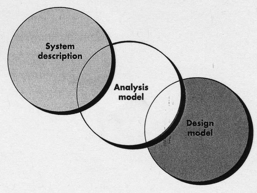
3 Elaboration: Building the Analysis Model An analysis model provides a description of the required information, functional, and behavioral domains for a computer based system. An analysis model will change during the requirements gathering with some areas stable and others being volatile. There are many ways to represent the model. Software is not visualizable 3
4 Domain Analysis Sources of domain knowledge Technical literature Existing application Customer surveys Expert advice Current/future requirements 4
5 Analysis Modeling Goals Describe what the customer requires Establish a basis for the creation of a software design Define a set of requirements that can be validated once the software is built 5
6 Deeper understanding the requirements From SRS, e.g. use case scenarios: What are the entities in the system? Class diagrams Data-flow diagram How these entities interact with each other? Sequence diagram Activity diagram Swim lane diagram The behavior of a complex object State diagram 6

7 Analysis Modeling Approaches 7
8 Analysis Modeling 8
9 9
10 Scenario based modeling Use cases text Use case diagrams Activity diagram Visualizing the logic within a use case: scenarios Swim lane diagram Split activities among actors. 10

11 Scenario-based Modeling Write Use-Cases Develop an Activity Diagram 11

12 An Activity Diagram Similar to a flowchart: Round rectangles imply specific system functions Arrows represent flow through the system Diamonds depict a branching decision 12

13 Swim Lane Diagram Swim Lane Diagram Represents flow of activities indicating which actor has responsibility for the action. Responsibilities are represented as parallel segments that divide the diamond vertically, like the lanes in a swimming pool. 13
14 Class based modeling Class diagram Entities Attributes Behaviors 14

15 Elaborating Use Cases Each usage scenario implies a set of objects that are manipulated as an actor interacts with them 15

16 Elaborating Use Cases The behavior of a computer- based system can have a profound effect on the design that is chosen, therefore the analysis model must provide modeling elements that depict behavior: 16

17 Class-Based Modeling Class diagram for the system class 17

18 Class Diagram

19 Class name attributes operation s A class encapsulates state (attribute) and behavior (operations). Each attribute has a type. Each operation has a signature. The class name is the only mandatory information.

20 Generalization Generalization relationships denote inheritance between classes. The children classes inherit the attributes and operations of the parent class. Indicated by a hollow arrow

21 Association Indicated by a solid arrow line from the source class to the target class Can be bi-directional represented by lines without arrow heads Don t usually put the association down as an attribute in the class
22 Aggregation If the association conveys the information that one object is part of another object ( has-a ), but their lifetimes are independent (they could exist independently). Aggregation is stronger than association, unidirectional. There is a container and one or more contained objects. For example, we may say that a Department contains a set of Employees, or that a Faculty contains a set of Teachers. An aggregation relationship is indicated by placing a white diamond at the end of the association next to the aggregate class. 22
23 Composition Even stronger than aggregation is composition. There is composition when an object is contained in another object, and it can exist only as long as the container exists and it only exists for the benefit of the container. Examples of composition are the relationship Invoice-Invoice Line, and Drawing-Figure. A composition is shown by a black diamond on the end of association next to the composite class. An aggregation is a special form of association; composition is a stronger form of aggregation. Both aggregation and composition are a part-whole hierarchy. 23
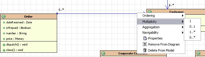
24 Multiplicity

25 Candidate classes: Noun extraction Company XYZ has two types of customers, corporate customers and personal customers. All customers can place orders. Every order is placed by a customer.

26 Evaluating a Class/Class Diagram 1. Intention-revealing naming: Does the name of the object convey its abstractions? Does the abstraction have a natural meaning and use in the domain? 2. Single Responsibility: Do the name, main responsibility statement data and functions align???
27 Flow-Oriented Modeling Data Flow Diagrams show the input-process-output view of a system. DFD s are not part of UML, but a complement to UML. There is a natural tendency to show too much detail too soon. Start at a high level and work your way down one process at a time. 27

28 Flow-Oriented Modeling DFD for the SafeHome Security function 28

29 Flow-Oriented Modeling Level 1 DFD for SafeHome Security Function 29

30 Flow-Oriented Modeling Level 2 DFD that refines the monitor sensors process 30
31 Behavioral Models Sequence Diagram How the entities interact with each other For further design analysis State Diagram How a complex object behaves 31
32 UML Sequence Diagrams 32
33 UML Sequence Diagrams Used during requirements analysis To refine use case descriptions To find additional objects ( participating objects ) Used during system design to refine subsystem interfaces Performance analysis
34 A Sample Scenario A player rolls the dice and gets a 6. The player moves 6 cells. The player lands on a cell that is an un-owned property. The player s turn is over. Objects Player Dice Cell Property Not all nouns become objects such as turn
35 UML Sequence Diagrams Objects are represented by columns (first column is actor that initiates use case) Messages are represented by arrows Activations of an operation are represented by narrow rectangles Player Dice Cell Property rolldice DiceValue(6) MoveCell(6) isownedproperty(false) isownedproperty No significance to the horizontal orderings of the objects Return values are optionally indicated using a dashed arrow with a label indicating the return value Suggestion: not to indicate the return values when it is obvious what is being returned
36 Scenario A player rolls the dice and gets a 6. The player moves 6 cells. The player lands on a cell that is an un-owned property. The player s turn is over. Not all nouns become objects such as turn Player Dice Cell Property rolldice DiceValue(6) MoveCell(6) isownedproperty(false) isownedproperty
37 Conditional Logic If the player lands on a cell that is an unowned property, the player s turn is over. If the player lands on a cell that is owned, the player must pay rent to the owner of the property. Then, the player s turn is over. Player Dice Cell Property Owner rolldice DiceValue(n) MoveCells(n) [isownedproperty] isownedproperty(false) [else] isownedproperty(true,owner) PayOwner
38 UML State Diagram 38
39 State Diagram A state diagram (also called state machine diagram) depict the various states that an object may be in and the transitions between those states. Appropriate to be developed for complex objects. From UML Distilled (pp ): A lock in a haunted house: keep valuables in a safe that s hard to find To reveal the lock to the safe, I have to remove a strategic candle from its holder, but this will reveal the lock only while the door is closed. In the Wait state, if the candle is removed providing the door is closed, you reveal the lock and move to the Lock state. Once I can see the lock, I can insert my key to open the safe. For extra safety, I make sure that I can open the safe only if I re-place the candle first. If a thief neglects this precaution, I ll unleash a killer rabbit to him.
40 State Diagram From UML Distilled (pp ): A lock in a haunted house: keep valuables in a safe that s hard to find To reveal the lock to the safe, I have to remove a strategic candle from its holder, but this will reveal the lock only while the door is closed. In the Wait state, if the candle is removed providing the door is closed, you reveal the lock and move to the Lock state. Once I can see the lock, I can insert my key to open the safe. For extra safety, I make sure that I can open the safe only if I re-place the candle first. If a thief neglects this precaution, I ll unleash a killer rabbit to him.
41 States States are represented by the values of the attributes or data members of an object. Initial state state transition Terminal state
42 Transitions Transitions are the result of the invocation of a method that causes an important change in state. Each transition has a label that comes in three parts. All the parts are optional. trigger-signature [guard]/activity candle removed [door closed]/reveal lock The trigger-signature is usually a single event that triggers a potential change of state. Missing trigger-signature [rare] you take the transition immediately. The guard, if present, is a Boolean condition that must be true for the transition to be taken. Missing guard always take the transition. The activity is some behavior that s executed during the transition. Missing activity don t do anything during the transition.
43 activity: behavior that s executed during the transition trigger-signature: event that causes a potential change of state guard: Boolean condition that must be true for transition to happen
44 Rules for State Diagrams There is one initial state (can be multiple final states). Every state can be reached from the initial state. From each state, there must be a path to a final state. Every transition between states must be labeled with an event that will cause that transition. When an event occurs, you can take only one transition. If you have multiple transitions with the same event, the guards must be mutually exclusive. Transitions that are not shown are illegal OR show transitions that cause errors.
UML (Unified Modeling Language)
") UML (Unified Modeling Language) UML Outline Software Institute of Nanjing University 2009 Instructor 刘嘉 (Liu Jia) Email : liujia@software.nju.edu.cn ext : 509 Office : 705 2 References [1] The Unified
UML (Unified Modeling Language) UML Outline Software Institute of Nanjing University 2009 Instructor 刘嘉 (Liu Jia) Email : liujia@software.nju.edu.cn ext : 509 Office : 705 2 References [1] The Unified
SOFTWARE DESIGN COSC 4353 / Dr. Raj Singh
 SOFTWARE DESIGN COSC 4353 / 6353 Dr. Raj Singh UML - History 2 The Unified Modeling Language (UML) is a general purpose modeling language designed to provide a standard way to visualize the design of a
Software Service Engineering
 Software Service Engineering Lecture 4: Unified Modeling Language Doctor Guangyu Gao Some contents and notes selected from Fowler, M. UML Distilled, 3rd edition. Addison-Wesley Unified Modeling Language
State Machine Diagrams
 107 Chapter 10 State Machine Diagrams State machine diagrams are a familiar technique to describe the behavior of a System. Various forms of State diagrams haue been around since the 1960s and the earliest
Chapter 10. Object-Oriented Analysis and Modeling Using the UML. McGraw-Hill/Irwin
 Chapter 10 Object-Oriented Analysis and Modeling Using the UML McGraw-Hill/Irwin Copyright 2007 by The McGraw-Hill Companies, Inc. All rights reserved. Objectives 10-2 Define object modeling and explain
Class diagrams. Modeling with UML Chapter 2, part 2. Class Diagrams: details. Class diagram for a simple watch
 Class diagrams Modeling with UML Chapter 2, part 2 CS 4354 Summer II 2014 Jill Seaman Used to describe the internal structure of the system. Also used to describe the application domain. They describe
Meltem Özturan
 Meltem Özturan www.mis.boun.edu.tr/ozturan/samd 1 2 Modeling System Requirements Object Oriented Approach to Requirements OOA considers an IS as a set of objects that work together to carry out the function.
Class diagrams. Modeling with UML Chapter 2, part 2. Class Diagrams: details. Class diagram for a simple watch
 Class diagrams Modeling with UML Chapter 2, part 2 CS 4354 Summer II 2015 Jill Seaman Used to describe the internal structure of the system. Also used to describe the application domain. They describe
Course "Softwaretechnik" Book Chapter 2 Modeling with UML
 Course "Softwaretechnik" Book Chapter 2 Modeling with UML Lutz Prechelt, Bernd Bruegge, Allen H. Dutoit Freie Universität Berlin, Institut für Informatik http://www.inf.fu-berlin.de/inst/ag-se/ Modeling,
CS 370 REVIEW: UML Diagrams D R. M I C H A E L J. R E A L E F A L L
 CS 370 REVIEW: UML Diagrams D R. M I C H A E L J. R E A L E F A L L 2 0 1 5 Introduction UML Unified Modeling Language Very well recognized specification for modeling architectures, use cases, etc. UML
Lab Manual. Object Oriented Analysis And Design. TE(Computer) VI semester
 VI semester") Lab Manual Object Oriented Analysis And Design TE(Computer) VI semester Index Sr. No. Title of Programming Assignment Page No. 1 2 3 4 5 6 7 8 9 10 Study of Use Case Diagram Study of Activity Diagram Study
Lab Manual Object Oriented Analysis And Design TE(Computer) VI semester Index Sr. No. Title of Programming Assignment Page No. 1 2 3 4 5 6 7 8 9 10 Study of Use Case Diagram Study of Activity Diagram Study
Modeling with UML. (1) Use Case Diagram. (2) Class Diagram. (3) Interaction Diagram. (4) State Diagram
 Use Case Diagram. (2) Class Diagram. (3) Interaction Diagram. (4) State Diagram") Modeling with UML A language or notation intended for analyzing, describing and documenting all aspects of the object-oriented software system. UML uses graphical notations to express the design of software
Modeling with UML A language or notation intended for analyzing, describing and documenting all aspects of the object-oriented software system. UML uses graphical notations to express the design of software
MSc programme (induction week) Department of Informatics INTRODUCTION TO UML
 Department of Informatics INTRODUCTION TO UML") MSc programme (induction week) Department of Informatics INTRODUCTION TO UML Some of this material is based on Bernd Bruegge and Allen H. Dutoit (2009) Object-Oriented Software Engineering: Using UML,
MSc programme (induction week) Department of Informatics INTRODUCTION TO UML Some of this material is based on Bernd Bruegge and Allen H. Dutoit (2009) Object-Oriented Software Engineering: Using UML,
Basic Structural Modeling. Copyright Joey Paquet,
 Basic Structural Modeling Copyright Joey Paquet, 2000 1 Part I Classes Copyright Joey Paquet, 2000 2 Classes Description of a set of objects sharing the same attributes, operations and semantics Abstraction
12 Tutorial on UML. TIMe TIMe Electronic Textbook
 TIMe TIMe Electronic Textbook 12 Tutorial on UML Introduction......................................................2.................................................3 Diagrams in UML..................................................3
06. Analysis Modeling
 06. Analysis Modeling Division of Computer Science, College of Computing Hanyang University ERICA Campus 1 st Semester 2017 Overview of Analysis Modeling 1 Requirement Analysis 2 Analysis Modeling Approaches
Solved Question Paper June 2017
 Solved Question Paper June 2017 1.a) What are the benefits of Object Oriented Methodology in real life applications? Briefly explain each element of the state diagram with respect to dynamic modeling.
7. UML Sequence Diagrams Page 1 of 1
 7. UML Sequence Diagrams Page 1 of 1 Sequence Diagram in UML In the last article, we saw Activity diagrams, the notations to be used in Activity diagrams, their significance, and how to build an Activity
Chapter 2, lecture 2 Modeling with UML
 Object-Oriented Software Engineering Using UML, Patterns, and Java Chapter 2, lecture 2 Modeling with UML Overview: More detail on modeling with UML Use case diagrams Class diagrams Sequence diagrams Activity
BASICS OF UML (PART-2)
") BASICS OF UML (PART-2) 1 USE CASE DIAGRAMS 2 USE CASE DIAGRAMS Use Case Model: a view of a system that emphasizes the behavior as it appears to outside users. A use case model partitions system functionality
BASICS OF UML (PART-2) 1 USE CASE DIAGRAMS 2 USE CASE DIAGRAMS Use Case Model: a view of a system that emphasizes the behavior as it appears to outside users. A use case model partitions system functionality
Oral Questions. Unit-1 Concepts. Oral Question/Assignment/Gate Question with Answer
 Unit-1 Concepts Oral Question/Assignment/Gate Question with Answer The Meta-Object Facility (MOF) is an Object Management Group (OMG) standard for model-driven engineering Object Management Group (OMG)
Design Patterns. Design Patterns
 Design Patterns As software engineers, we commonly have to make decisions about how to create complex objects, how to encapsulate some actions, how to allow for the undoing of certain operations, etc.
Chapter : Analysis Modeling
 Chapter : Analysis Modeling Requirements Analysis Requirements analysis Specifies software s operational characteristics Indicates software's interface with other system elements Establishes constraints
Object Relationships UML Class diagrams. Software Requirements and Design CITS 4401 Lecture 4
 Object Relationships UML Class diagrams Software Requirements and Design CITS 440 Lecture 4 UML Class Diagrams Describe the static structure of the system classes, class attributes, associations between
UML- a Brief Look UML and the Process
 UML- a Brief Look UML grew out of great variety of ways Design and develop object-oriented models and designs By mid 1990s Number of credible approaches reduced to three Work further developed and refined
OO Techniques & UML Class Diagrams
 OO Techniques & UML Class Diagrams SE3A04 Tutorial Jason Jaskolka Department of Computing and Software Faculty of Engineering McMaster University Hamilton, Ontario, Canada jaskolj@mcmaster.ca October 17,
STATE MACHINES. Figure 1: State Machines
 STATE MACHINES Figure 1: State Machines state machine A state machine is a behavior that specifies the sequences of states an object goes through during its lifetime in response to events. Graphically,
MAHARASHTRA STATE BOARD OF TECHNICAL EDUCATION (Autonomous) (ISO/IEC Certified) MODEL ANSWER
 (ISO/IEC Certified) MODEL ANSWER") Important Instructions to examiners: 1) The answers should be examined by key words and not as word-to-word as given in the model answer scheme. 2) The model answer and the answer written by candidate
Important Instructions to examiners: 1) The answers should be examined by key words and not as word-to-word as given in the model answer scheme. 2) The model answer and the answer written by candidate
Department of Industrial Engineering. Sharif University of Technology
 Department of Industrial Engineering Sharif University of Technology Session #15 Instructor Omid Fatahi Valilai, Ph.D. Industrial Engineering Department, Sharif University of Technology Email: Fvalilai@sharif.edu,
SE Assignment III. 1. List and explain primitive symbols used for constructing DFDs. Illustrate the use of these symbols with the help of an example.
 SE Assignment III 1. List and explain primitive symbols used for constructing DFDs. Illustrate the use of these symbols with the help of an example. There are essentially 5 different types of symbols used
UNIT-4 Behavioral Diagrams
 UNIT-4 Behavioral Diagrams P. P. Mahale Behavioral Diagrams Use Case Diagram high-level behaviors of the system, user goals, external entities: actors Sequence Diagram focus on time ordering of messages
Chapter 2: The Object-Oriented Design Process
 Chapter 2: The Object-Oriented Design Process In this chapter, we will learn the development of software based on object-oriented design methodology. Chapter Topics From Problem to Code The Object and
On to Iteration 3, and Activity Diagrams CSSE 574: Session 6, Part 1
 On to Iteration 3, and Activity Diagrams CSSE 574: Session 6, Part 1 Steve Chenoweth Phone: Office (812) 877-8974 Cell (937) 657-3885 Email: chenowet@rose-hulman.edu On to Iteration 3: NextGen POS Failover
Object-Oriented Systems Analysis and Design Using UML
 10 Object-Oriented Systems Analysis and Design Using UML Systems Analysis and Design, 8e Kendall & Kendall Copyright 2011 Pearson Education, Inc. Publishing as Prentice Hall Learning Objectives Understand
Unified Modeling Language (UML)
") Appendix H Unified Modeling Language (UML) Preview The Unified Modeling Language (UML) is an object-oriented modeling language sponsored by the Object Management Group (OMG) and published as a standard
Appendix H Unified Modeling Language (UML) Preview The Unified Modeling Language (UML) is an object-oriented modeling language sponsored by the Object Management Group (OMG) and published as a standard
Lesson 11. W.C.Udwela Department of Mathematics & Computer Science
 Lesson 11 INTRODUCING UML W.C.Udwela Department of Mathematics & Computer Science Why we model? Central part of all the activities We build model to Communicate Visualize and control Better understand
Principles of Software Construction: Objects, Design, and Concurrency
 Principles of Software Construction: Objects, Design, and Concurrency Designing (sub-) systems A formal design process Charlie Garrod Michael Hilton School of Computer Science 1 Administrivia Optional
BASICS OF BPMN BASIC BPMN SUBSET OKAY, SO WHAT DO I REALLY NEED TO KNOW? CHAPTER 2
 MicroGuide.book Page 23 Friday, June 17, 2011 12:26 PM CHAPTER 2 BASICS OF BPMN In the introduction, we defined BPMN concepts as the key elements of a business process model. This chapter presents BPMN
Introduction to Software Engineering. 5. Modeling Objects and Classes
 Introduction to Software Engineering 5. Modeling Objects and Classes Roadmap > UML Overview > Classes, attributes and operations > UML Lines and Arrows > Parameterized Classes, Interfaces and Utilities
Object Oriented Modeling
 Overview UML Unified Modeling Language What is Modeling? What is UML? A brief history of UML Understanding the basics of UML UML diagrams UML Modeling tools 2 Modeling Object Oriented Modeling Describing
Data and Process Modeling
 Data and Process Modeling Chapter 3 Data Models Start with User Views Data Model Diagramming Entity Relationship Diagram (ERD) is most common Original by Peter Chen in 1976 Common ERD Elements: Entities
Chapter 2 Entity-Relationship Data Modeling: Tools and Techniques. Fundamentals, Design, and Implementation, 9/e
 Chapter 2 Entity-Relationship Data Modeling: Tools and Techniques Fundamentals, Design, and Implementation, 9/e Three Schema Model ANSI/SPARC introduced the three schema model in 1975 It provides a framework
Interactions A link message
 Interactions An interaction is a behavior that is composed of a set of messages exchanged among a set of objects within a context to accomplish a purpose. A message specifies the communication between
Introduction To UML PART II State Diagrams
 Introduction To UML PART II State Diagrams The behavioral elements show how parts of a UML model change over time. As the system interacts with users and possibly with other systems, the objects that make
Component Design. Systems Engineering BSc Course. Budapest University of Technology and Economics Department of Measurement and Information Systems
 Component Design Systems Engineering BSc Course Budapest University of Technology and Economics Department of Measurement and Information Systems Traceability Platform-based systems design Verification
ASSIGNMENT- I Topic: Functional Modeling, System Design, Object Design. Submitted by, Roll Numbers:-49-70
 ASSIGNMENT- I Topic: Functional Modeling, System Design, Object Design Submitted by, Roll Numbers:-49-70 Functional Models The functional model specifies the results of a computation without specifying
Unit Wise Questions. Unit-1 Concepts
 Unit Wise Questions Unit-1 Concepts Q1. What is UML? Ans. Unified Modelling Language. It is a Industry standard graphical language for modelling and hence visualizing a blue print of all the aspects of
CS487 Midterm Exam Summer 2005
 1. (4 Points) How does software differ from the artifacts produced by other engineering disciplines? 2. (10 Points) The waterfall model is appropriate for projects with what Characteristics? Page 1 of
Practical UML - A Hands-On Introduction for Developers
 Practical UML - A Hands-On Introduction for Developers By: Randy Miller (http://gp.codegear.com/authors/edit/661.aspx) Abstract: This tutorial provides a quick introduction to the Unified Modeling Language
Lecture 5 STRUCTURED ANALYSIS. PB007 So(ware Engineering I Faculty of Informa:cs, Masaryk University Fall Bühnová, Sochor, Ráček
 Lecture 5 STRUCTURED ANALYSIS PB007 So(ware Engineering I Faculty of Informa:cs, Masaryk University Fall 2015 1 Outline ² Yourdon Modern Structured Analysis (YMSA) Context diagram (CD) Data flow diagram
A - 1. CS 494 Object-Oriented Analysis & Design. UML Class Models. Overview. Class Model Perspectives (cont d) Developing Class Models
 Developing Class Models") CS 494 Object-Oriented Analysis & Design UML Class Models Overview How class models are used? Perspectives Classes: attributes and operations Associations Multiplicity Generalization and Inheritance Aggregation
CS 494 Object-Oriented Analysis & Design UML Class Models Overview How class models are used? Perspectives Classes: attributes and operations Associations Multiplicity Generalization and Inheritance Aggregation
APPENDIX M INTRODUCTION TO THE UML
 M INTRODUCTION TO THE UML This appendix, written only for those readers not familiar with the topic, provides a brief introduction, which cannot be considered as exhaustive, to the UML. The UML is a general-purpose
Engineering Design w/embedded Systems
 1 / 40 Engineering Design w/embedded Systems Lecture 33 UML Patrick Lam University of Waterloo April 4, 2013 2 / 40 What is UML? Unified Modelling Language (UML): specify and document architecture of large
Practical UML : A Hands-On Introduction for Developers
 Borland.com Borland Developer Network Borland Support Center Borland University Worldwide Sites Login My Account Help Search Practical UML : A Hands-On Introduction for Developers - by Randy Miller Rating:
UML Fundamental. OutLine. NetFusion Tech. Co., Ltd. Jack Lee. Use-case diagram Class diagram Sequence diagram
 UML Fundamental NetFusion Tech. Co., Ltd. Jack Lee 2008/4/7 1 Use-case diagram Class diagram Sequence diagram OutLine Communication diagram State machine Activity diagram 2 1 What is UML? Unified Modeling
Requests Charges. Librarian. University affiliated patrons students, faculty, staff. Media Center Staff
 Catherine Rutan INFO 530-901 Dr. Valerie Yonker Circulation of Media Materials from University Media Center: Requests Charges Librarian Circulation Desk Attendant Inquires University ID # (Primary Key)
Introduction to Software Engineering. 6. Modeling Behaviour
 Introduction to Software Engineering 6. Modeling Behaviour Roadmap > Use Case Diagrams > Sequence Diagrams > Collaboration (Communication) Diagrams > Activity Diagrams > Statechart Diagrams Nested statecharts
Design Engineering. Dr. Marouane Kessentini Department of Computer Science
 Design Engineering Dr. Marouane Kessentini Department of Computer Science 1 Design Starts mostly from/with requirements (evolving mostly from functionalities and other non functional characteristics) How
(C) 2010 Pearson Education, Inc. All rights reserved. Dr. Marenglen Biba
 2010 Pearson Education, Inc. All rights reserved. Dr. Marenglen Biba") Dr. Marenglen Biba In Chapters 12 13, you design and implement an object-oriented automated teller machine (ATM) software system. Concise, carefully paced, complete design and implementation experience.
Dr. Marenglen Biba In Chapters 12 13, you design and implement an object-oriented automated teller machine (ATM) software system. Concise, carefully paced, complete design and implementation experience.
THE UNIFIED MODELING LANGUAGE
 3 THE UNIFIED MODELING LANGUAGE CHAPTER OUTLINE Class Diagrams 36 Basic Class Diagram Notation 37 Class Diagrams for Database Design 39 Example from the Music Industry 44 Activity Diagrams 47 Activity
SOFTWARE ENGINEERING UML FUNDAMENTALS. Saulius Ragaišis.
 SOFTWARE ENGINEERING UML FUNDAMENTALS Saulius Ragaišis saulius.ragaisis@mif.vu.lt Information source Slides are prepared on the basis of Bernd Oestereich, Developing Software with UML: Object- Oriented
CMPT 354 Database Systems I
 CMPT 354 Database Systems I Chapter 4.6 Kifer Reference Book UML (Unified Modeling Language) Class Modeling UML Introduction UML (Unified Modeling Language) is a set of specifications for software engineering
CSE 403: Software Engineering, Spring courses.cs.washington.edu/courses/cse403/15sp/ UML Class Diagrams. Emina Torlak
 CSE 403: Software Engineering, Spring 2015 courses.cs.washington.edu/courses/cse403/15sp/ UML Class Diagrams Emina Torlak emina@cs.washington.edu Outline Designing classes Overview of UML UML class diagrams
Structured and Object Oriented Analysis and Design
 RAMRAO ADIK INSTITUTE OF TECHNOLOGY, NERUL Department of Computer Engineering Lab Manual Structured and Object Oriented Analysis and Design 2015-2016 List of Experiments Subject: Structured and object
CS 4604: Introduction to Database Management Systems. B. Aditya Prakash Lecture #5: Entity/Relational Models---Part 1
 CS 4604: Introduction to Database Management Systems B. Aditya Prakash Lecture #5: Entity/Relational Models---Part 1 E/R: NOT IN BOOK! IMPORTANT: Follow only lecture slides for this topic! Differences
Chapter 4. Capturing the Requirements. 4th Edition. Shari L. Pfleeger Joanne M. Atlee
 Chapter 4 Capturing the Requirements Shari L. Pfleeger Joanne M. Atlee 4th Edition It is important to have standard notations for modeling, documenting, and communicating decisions Modeling helps us to
SE 1: Software Requirements Specification and Analysis
 SE 1: Software Requirements Specification and Analysis Lecture 9: UML Class (Concept), Object, Communication Diagrams Nancy Day, Davor Svetinović http://www.student.cs.uwaterloo.ca/ cs445/winter2006 uw.cs.cs445
Software Engineering. Page 1. Objectives. Object-Behavioural Modelling. Analysis = Process + Models. Case Study: Event Identification
 Software Engineering Object-Oriented Analysis (State and Interaction Diagrams) James Gain (jgain@cs.uct.ac.za) http://people.cs.uct.ac.za/~jgain 1. Show the object-behaviour design process Objectives 2.
MAHARASHTRA STATE BOARD OF TECHNICAL EDUCATION (Autonomous) (ISO/IEC Certified)
 (ISO/IEC Certified)") Subject Code: 17630 Model Answer Page No: 1 /32 Important Instructions to examiners: 1) The answers should be examined by keywords and not as word-to-word as given in the model answer scheme. 2) The model
Subject Code: 17630 Model Answer Page No: 1 /32 Important Instructions to examiners: 1) The answers should be examined by keywords and not as word-to-word as given in the model answer scheme. 2) The model
 0. Database Systems 1.1 Introduction to DBMS Information is one of the most valuable resources in this information age! How do we effectively and efficiently manage this information? - How does Wal-Mart
Introducing the UML Eng. Mohammed T. Abo Alroos
 Introducing the UML Eng. Mohammed T. Abo Alroos Islamic University of Gaza Introduction to the UML: The UML stands for Unified Modeling Language. It was released in 1997 as a method to diagram software
Unified Modeling Language
 Unified Modeling Language Modeling Applications using Language Mappings Programmer s Reference Manual How to use this Reference Card: The consists of a set of fundamental modeling elements which appear
From Analysis to Design. LTOOD/OOAD Verified Software Systems
 From Analysis to Design 1 Use Cases: Notation Overview Actor Use case System X System boundary UCBase «extend» UCExt Actor A UCVar1 UCVar2 Extending case Generalization «include» Actor B UCIncl Included
Object-Oriented Software Engineering Practical Software Development using UML and Java
 Object-Oriented Software Engineering Practical Software Development using UML and Java Chapter 5: Modelling with Classes Lecture 5 5.1 What is UML? The Unified Modelling Language is a standard graphical
A l Ain University Of Science and Technology
 A l Ain University Of Science and Technology 4 Handout(4) Database Management Principles and Applications The Entity Relationship (ER) Model http://alainauh.webs.com/ 1 In this chapter, you will learn:
+ Public - Private # Protected # Protected (Overridable) Static
 Static") Element Containers + attribute1:type = defaultvalue + attribute2:type - attribute3:type + operation1(params):returntype - operation2(params) - operation3() This container is to be used when displaying
Element Containers + attribute1:type = defaultvalue + attribute2:type - attribute3:type + operation1(params):returntype - operation2(params) - operation3() This container is to be used when displaying
Process Modeling. Chapter 7. Class 05: Process Modeling 1
 Process Modeling Chapter 7 Class 05: Process Modeling 1 Process Design Seldom the responsibility of the database designer or DBA However, understanding the basics aids communication with the process designers
Process Modeling. Business Process Example. Process Design
 Process Modeling Chapter 7 Class 05: Process Modeling 1 Process Design Seldom the responsibility of the database designer or DBA However, understanding the basics aids communication with the process designers
Chapter 2 Entity-Relationship Data Modeling: Tools and Techniques. Fundamentals, Design, and Implementation, 9/e
 Chapter 2 Entity-Relationship Data Modeling: Tools and Techniques Fundamentals, Design, and Implementation, 9/e Three Schema Model ANSI/SPARC introduced the three schema model in 1975 It provides a framework
Goal: build an object-oriented model of the realworld system (or imaginary world) Slicing the soup: OOA vs. OOD
 Slicing the soup: OOA vs. OOD") Domain analysis Goal: build an object-oriented model of the realworld system (or imaginary world) Slicing the soup: OOA vs. OOD OOA concerned with what, not how OOA activities focus on the domain layer
Domain analysis Goal: build an object-oriented model of the realworld system (or imaginary world) Slicing the soup: OOA vs. OOD OOA concerned with what, not how OOA activities focus on the domain layer
Software Engineering Fall 2015 (CSC 4350/6350) TR. 5:30 pm 7:15 pm. Rao Casturi 09/29/2015
 TR. 5:30 pm 7:15 pm. Rao Casturi 09/29/2015") Software Engineering Fall 2015 (CSC 4350/6350) TR. 5:30 pm 7:15 pm Rao Casturi 09/29/2015 http://cs.gsu.edu/~ncasturi1 Class Announcements Grading is done for the Deliverable #2 (Requirement Elicitation)
Software Engineering Fall 2015 (CSC 4350/6350) TR. 5:30 pm 7:15 pm Rao Casturi 09/29/2015 http://cs.gsu.edu/~ncasturi1 Class Announcements Grading is done for the Deliverable #2 (Requirement Elicitation)
UML 2.0 UML 2.0. Scott Uk-Jin Lee. Division of Computer Science, College of Computing Hanyang University ERICA Campus
 UML 2.0 Division of Computer Science, College of Computing Hanyang University ERICA Campus Introduction to UML 2.0 UML Unified Modeling Language Visual language for specifying, constructing and documenting
Design and UML Class Diagrams
 Design and UML Class Diagrams 1 Suggested reading: Practical UML: A hands on introduction for developers http://dn.codegear.com/article/31863 UML DistilledCh. 3, by M. Fowler How do people draw / write
For 100% Result Oriented IGNOU Coaching and Project Training Call CPD TM : ,
 Course Code : MCS-032 Course Title : Object Oriented Analysis and Design Assignment Number : MCA (3)/032/Assign/2014-15 Assignment Marks : 100 Weightage : 25% Last Dates for Submission : 15th October,
Chapter 5: Structural Modeling
 Chapter 5: Structural Modeling Objectives Understand the rules and style guidelines for creating CRC cards, class diagrams, and object diagrams. Understand the processes used to create CRC cards, class
Vidyalankar. T.Y. Diploma : Sem. VI [IF/CM] Object Oriented Modeling and Design Prelim Question Paper Solution
![Vidyalankar. T.Y. Diploma : Sem. VI [IF/CM] Object Oriented Modeling and Design Prelim Question Paper Solution](/thumbs/86/94007497.jpg "Vidyalankar. T.Y. Diploma : Sem. VI [IF/CM] Object Oriented Modeling and Design Prelim Question Paper Solution") T.Y. Diploma : Sem. VI [IF/CM] Object Oriented Modeling and Design Prelim Question Paper Solution Q.1(a) Attempt any THREE of the following [12] Q.1(a) (i) What is modeling? Also state its four features.
T.Y. Diploma : Sem. VI [IF/CM] Object Oriented Modeling and Design Prelim Question Paper Solution Q.1(a) Attempt any THREE of the following [12] Q.1(a) (i) What is modeling? Also state its four features.
Darshan Institute of Engineering & Technology for Diploma Studies
 REQUIREMENTS GATHERING AND ANALYSIS The analyst starts requirement gathering activity by collecting all information that could be useful to develop system. In practice it is very difficult to gather all
Object Oriented Design. Program Design. Analysis Phase. Part 2. Analysis Design Implementation. Functional Specification
 Object Oriented Design Part 2 Analysis Design Implementation Program Design Analysis Phase Functional Specification Completely defines tasks to be solved Free from internal contradictions Readable both
Unified Modeling Language (UML) Class Diagram
 Class Diagram") 1 / 10 Unified Modeling Language (UML) Class Diagram Miaoqing Huang University of Arkansas Spring 2010 2 / 10 Outline 1 2 3 / 10 Class Diagram Class diagrams show the static structure of the classes that
1 / 10 Unified Modeling Language (UML) Class Diagram Miaoqing Huang University of Arkansas Spring 2010 2 / 10 Outline 1 2 3 / 10 Class Diagram Class diagrams show the static structure of the classes that
More on the Chen Notation
 More on the Chen Notation Reference: http://www.vertabelo.com/blog/technical-articles/chen-erd-notation Peter Chen, who developed entity-relationship modeling and published his work in 1976, was one of
What is a Class Diagram? A diagram that shows a set of classes, interfaces, and collaborations and their relationships
 Class Diagram What is a Class Diagram? A diagram that shows a set of classes, interfaces, and collaborations and their relationships Why do we need Class Diagram? Focus on the conceptual and specification
What is a Class Diagram? Class Diagram. Why do we need Class Diagram? Class - Notation. Class - Semantic 04/11/51
 What is a Class Diagram? Class Diagram A diagram that shows a set of classes, interfaces, and collaborations and their relationships Why do we need Class Diagram? Focus on the conceptual and specification
S T R U C T U R A L M O D E L I N G ( M O D E L I N G A S Y S T E M ' S L O G I C A L S T R U C T U R E U S I N G C L A S S E S A N D C L A S S D I A
 S T R U C T U R A L M O D E L I N G ( M O D E L I N G A S Y S T E M ' S L O G I C A L S T R U C T U R E U S I N G C L A S S E S A N D C L A S S D I A G R A M S ) WHAT IS CLASS DIAGRAM? A class diagram
Äriprotsesside modelleerimine ja automatiseerimine Loeng 7 Valdkonna mudel
 Äriprotsesside modelleerimine ja automatiseerimine Loeng 7 Valdkonna mudel Enn Õunapuu enn.ounapuu@ttu.ee What is a domain model? A domain model captures the most important types of objects in the context
BPMN Getting Started Guide
 Enterprise Studio BPMN Getting Started Guide 2017-09-21 Applies to: Enterprise Studio 3.0.0, Team Server 3.0.0 Table of contents 1 About modeling with BPMN 5 1.1 What is BPMN? 5 1.2 BPMN modeling 5 1.3
Object-Oriented Systems Development: Using the Unified Modeling Language
 Object-Oriented Systems Development: Using the Unified Modeling Language Chapter 5: Unified Modeling Language Goals Modeling. Unified modeling language. Class diagram. Use case diagram. Interaction diagrams.
Requirements Engineering
 Chapter 3: Requirements Modeling Requirements Engineering Objectives In this chapter, you will learn about: Functional requirements Modeling requirements Overview of basic modeling paradigms Gus Requirements
UML Essentials Dynamic Modeling
 UML Essentials Dynamic Modeling Excerpts from: Object Oriented Software Engineering by Lethbridge/Laganière and Applying UML and Patterns by Larman, C. Dynamic model (diagram) elements (model run-time)
SEEM4570 System Design and Implementation Lecture 11 UML
 SEEM4570 System Design and Implementation Lecture 11 UML Introduction In the previous lecture, we talked about software development life cycle in a conceptual level E.g. we need to write documents, diagrams,
Developing Shlaer-Mellor Models Using UML
 Developing Shlaer-Mellor Models Using UML Stephen J. Mellor Neil Lang Project Technology, Inc. 10940 Bigge Street San Leandro, California 94577 (510) 567-0255 http://www.projtech.com This position paper