LockView 5 / 5Pro CompX Database & Network Configuration & Installation Manual
|
|
|
- Sherman Morrison
- 6 years ago
- Views:
Transcription


1 LockView 5 / 5Pro CompX Database & Network Configuration & Installation Manual
 Configuring SQL Server for LockView... 7 Installing LockView 5... 17 Software Licensing - Registration Wizard... 22 Configuring LockView 5 using MS Access (standalone).")
2 TABLE OF CONTENTS CompX Database & Network Configuration & Installation Manual Introduction... 4 Installation Requirements... 5 Installing SQL Server Express...(online at Configuring SQL Server for LockView... 7 Installing LockView Software Licensing - Registration Wizard Configuring LockView 5 using MS Access (standalone) Configuring LockView 5 using MS SQL (networked Wi-Fi or Ethernet) Setting up the Network Module Network Tools... 42
3 TABLE OF CONTENTS continued Other manuals available as separate pdfs: CompX elock Manual Programming Guide CompX LockView Software Instruction Manual 3

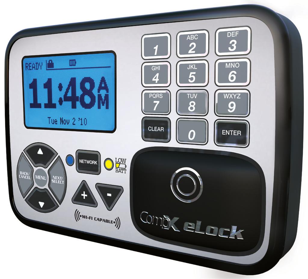
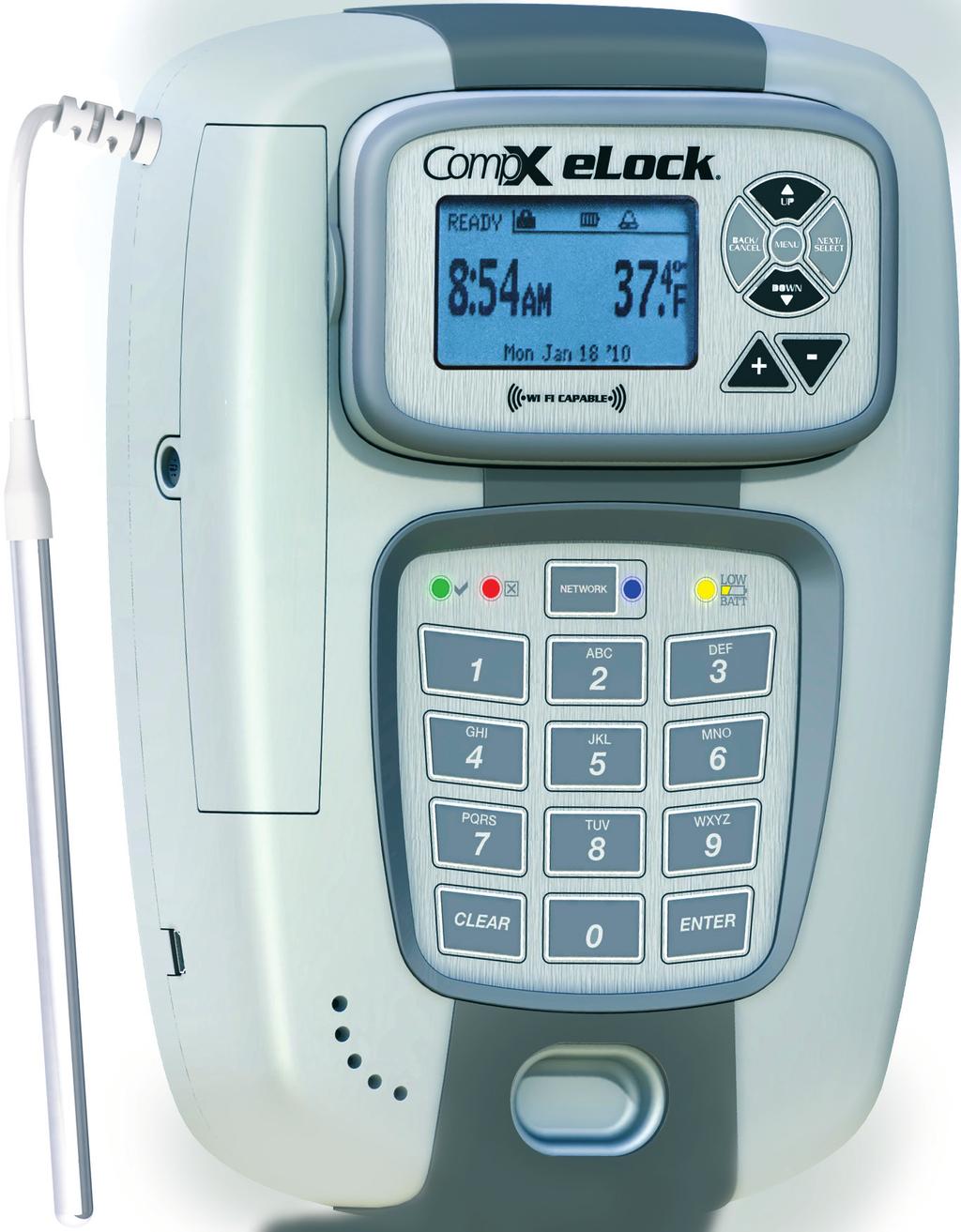
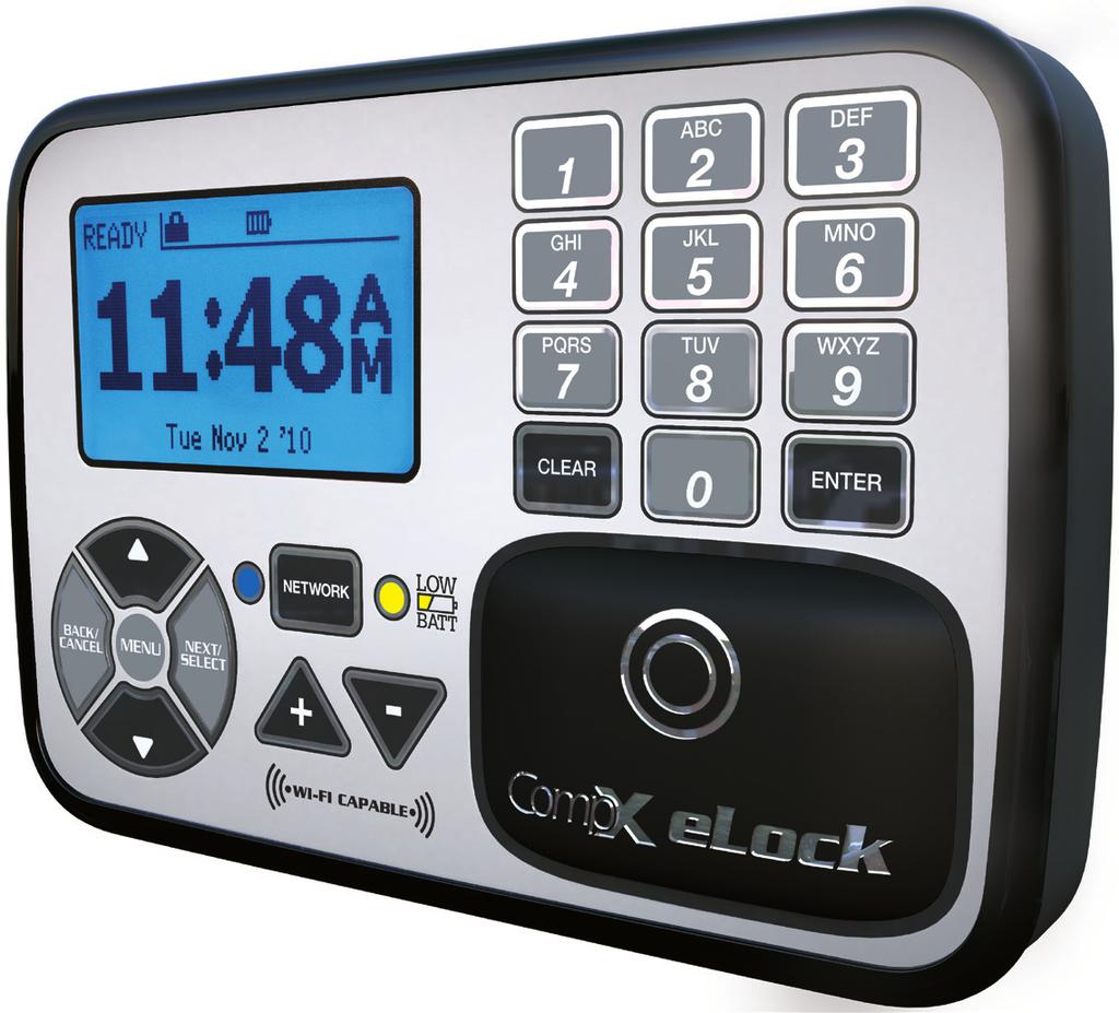
4 INTRODUCTION An authorized Operator of LockView can create a database of users and locks on a local or networked computer. Each user in this computer's database is assigned to a slot in each lock to which they have access. A lock's internal memory is divided into 3000 slots that store user information thereby giving each lock a maximum of 3000 users. The computer with LockView loaded onto it has the ability to connect to locks (directly, through a USB cable or through a computer network, using Ethernet or g Wi-Fi) and update the lock's memory to correspond with its own database. It is able to gather and manipulate a lock's audit trail, or past operation log. Audit trail information contains the lock s name, the name of the user attempting to gain access, the credential used, if access was granted or denied, and the date and time of each interaction. LockView 5/5Pro works with LockServ to communicate with locks. LockServ has the ability to communicate with multiple locks simultaneously over a computer network, eliminating the need for the Operator to visit each lock to update the lock s database, or download audit trails. Alternately, LockServ can communicate with locks using a USB cable if network hardware is not available. The following chart is intended to serve as a guide to provide for the most logical and efficient set-up of the CompX elock. CompX Database & Network Configuration & Installation Manual CompX LockView Software Instruction Manual CompX elock Manual Programming Guide Will the locks be or Ethernet networked? YES NO go to Is LockView Software going to be used? YES NO go to CompX elock Manual Programming Guide 4
5 INSTALLATION REQUIREMENTS Networked Installations Minimum system requirements: Vista, 7, 8, 8.1, 10, Server 2008/2012 and R2 versions. 4GB RAM - Processor 2.0 GHz or higher. (8GB recommended) 4GB Hard drive space SQL Server Standard, Enterprise, or SQL Express 2008/2012/2014 and R2 versions. If installing LockView on the Microsoft SQL Server please follow Microsoft SQL s minimum requirements ODBC connection required to Server Local Administrator Rights are required to install and register the software..net 4.0 Client Framework Minimum monitor resolution: 1024x768 Signed 32 bit and 64 bit WHQL drivers. Supports both 32 and 64 bit Operating Systems Compatible with VMWare Network System Definition LockView software and elock are on-site devices that work through the facility s internal network Wireless security protocols supported: WEP 64-key WEP 128-key WPA-PSK (TKIP) WPA2-PSK (AES) WPA-TKIP Enterprise* WPA-AES Enterprise* WPA-TKIP Enterprise* (skip RADIUS cert verification) WPA-AES Enterprise* (skip RADIUS cert verification) *EAP-TLS or PEAP-MSCHAPv2 Anticipated bandwidth traffic: In typical applications, with a 25 event audit trail and 4 user updates, the total transmission size would be approximately 20 kb (equal to a small ). Frequency of check-in is user defined. Factory default is set at twice daily (or every 12 hours). IP address Information: elocks DHCP or static IP address Server static IP address Connect One standard b/g wireless module or Lantronix 10/100 mbps Ethernet Module. RedPine wireless modules will be used in future products which will support b/g/n/a with 2.4ghz and 5ghz antenna s. Non-Networked Installations LockView will use an Access DB by default..net 4.0 or higher is required. Minimum monitor resolution: 1024x768 Optional SQL Server 2008 or better (Express versions ok). Follow LockView Client Install (in table above) for non-networked installs. Common Install for Non-Networked (Stand-Alone) Installations - Laptop with LockView installed. - When LockView is installed it automatically creates an Access database - The USB cable must be attached to a laptop and to the lock to make changes to lock or database. - Backup of Access DB is HIGHLY RECOMMENDED. 5
6 INSTALLATION REQUIREMENTS continued If SQL is used, refer to the following Common Install for Networked Installations list. Common Install for Networked Installations: - Server/PC with SQL Server and setup to be the LockView Server and a laptop with LockView Client Installed. - Backup of SQL Server is HIGHLY RECOMMENDED. Note: - Network module of lock must be programmed to point to the IP address of the computer with LockView Server (LockServ) installed. - LockView Server computer must have a static IP address. - All LockView Clients must also be able to connect to the LockView SQL DB through ODBC. - Network Modules need to be setup/changed with the USB cable. This is the main reason a laptop with LockView Client is required. See pages for setup. - There should only be one computer set up to be the LockView Server. - There should only be one LockView SQL Database. How the Network Modules work with SQL and LockView. - The Network Modules must be setup to communicate with the Server through its IP Address. This can be set in LockView with the USB cable in the LockView Settings menu. - The Server IP Address programmed in the network modules is the computer that is set up to be the LockView server. - LockView Server installs a service that runs automatically called LockService. - LockService must be running on the LockView Server for the Network Modules to update to the Database. - LockView Clients install the same LockServ. LockServ runs only when the LockView program is running. - LockView must have a valid ODBC setup to the SQL database to connect. 6


7 CONFIGURE MS SQL SERVER FOR LOCKVIEW 5/5PRO On the computer configured with Microsoft SQL Server Management Studio, go to Start - All Programs - Microsoft SQL Server - open Microsoft SQL Server Management Studio 1. Select the SQL Instance where the lvserver db will be installed. 2. Click File - Open - File 7

\lockview5\sql Script) then click Open 4.")
8 CONFIGURE MS SQL SERVER FOR LOCKVIEW 5/5PRO cont. 3. Navigate to the script lvserver_dbcreate.sql (on the install cd and (once installed) can be found typically at C:\Program Files (x86)\lockview5\sql Script) then click Open 4. Click Execute Be sure that master is the db selected in this box. 8

9 CONFIGURE MS SQL SERVER FOR LOCKVIEW 5/5PRO cont. 5. After a few seconds, the script runs and (1 row(s) affected) messages will be displayed. Click F5 (to refresh the screen) 6. Steps 6 and 7 allow the service LockService to run properly due to it running as Local System by default. Local System does not have access to the database by default. Grant db_owner Privileges to NT Authority\ SYSTEM - Expand Security, Expand Logins, and right-click NT Authority\SYSTEM - Select Properties 9

10 CONFIGURE MS SQL SERVER FOR LOCKVIEW 5/5PRO cont. 7. Select User Mapping Select LockView5 or the database that was created if changed from default Select db_owner Click OK to Save the changes Note: If Steps 6 and 7 do not work for your environment you can also change the Logon Account to the Service LockService to an Account that has db_owner privileges to the database if desired. 10

11 CONFIGURE MS SQL SERVER FOR LOCKVIEW 5/5PRO cont. 8. Grant DBO privilege to database and required users - Expand Security and right-click Logins. Select New Login 11
12 CONFIGURE MS SQL SERVER FOR LOCKVIEW 5/5PRO cont. 9. Create the login as needed under the General tab 10. Select User Mapping - Check the box next to the LockView database that was created with the SQL script - Check the box db_owner - Click OK to save the user - Repeat steps 9 and 10 for all users that will need access to the database 12
 Click")
13 CONFIGURE MS SQL SERVER FOR LOCKVIEW 5/5PRO cont. 11. Right Click on the Server\(Instance Name) Click Properties 13

14 CONFIGURE MS SQL SERVER FOR LOCKVIEW 5/5PRO cont. 12. Select Connections and Check the box Allow remote connections to this server. Click OK. Close out of the Microsoft SQL Management Studio 14


15 13. Open SQL Server Configuration Manager 14. Be sure that SQL Server (Instance Name) is enabled and running. Start Mode should be Automatic for SQL Server. 15

16 15. Click on SQL Server Network Configuration, click on Protocols for (Instance Name). Enable TCP/IP, Named Pipes, and Shared Memory. 16. Open SQL Native Client 10.0 Configuration, Click Client Protocols, enable Shared Memory, TCP/IP, Named Pipes. Close out of SQL Server Configuration Manager. 16


17 INSTALL LOCKVIEW 5/5PRO Note: The person installing LockView must have ADMINISTRATIVE RIGHTS on the computer where LockView will be installed. Insert LockView 5 USB drive If the LockView Software did not autorun: - Select Windows START button in bottom left corner of screen. - Select RUN - Select BROWSE - Look in the appropriate USB Drive - Select the Autorun.exe file 1. Install Shield will prepare to install. 2. Click Next 17


18 INSTALL LOCKVIEW 5/5PRO continued 3. Click Next 4. Read agreement, if acceptable, click I accept the terms in this agreement, then click Next 18


19 INSTALL LOCKVIEW 5/5PRO continued 5. Click Next (It is not recommended to install LockView at different locations other than the default.) 6. Select Install LockView Server for server install and Install LockView client for client install, then click Next. Note: - If this is a Standalone or MS Access installation, select Install LockView Client. - LockView Server should only be selected if this is the main lock server. - There should only be one LockView Server for Networked installs. - Multiple LockView Clients maybe installed. - Non-Networked installs only require LockView Client 19


20 INSTALL LOCKVIEW 5/5PRO continued 7. Click Install 8. Installation begins 20

21 INSTALL LOCKVIEW 5/5PRO continued 9. Click Finish Continue to document: Configure LockView for SQL (pages 30-35) Or Configure LockView for Access (pages 28-29) 11. Restart computer. 12. After the reboot is completed below is the LockServ Icon that will appear in the toolbar. If LockView was installed as a Server, LockServ will run as a service and the icon will always be present. If LockView was installed as a Client, the LockServ icon will only be displayed when LockView is open. 21


22 SOFTWARE LICENSING - REGISTRATION WIZARD 1. If connected to the internet or have on the computer, please click on Online Activation. If not, please call the CompX Technical Support Line between 8 am and 5 pm Monday - Friday and have the USB drive, serial number and Site Code available. Note: Enter Serial Number exactly as it appears on the sticker. You must include the spaces (ie not ) 22


23 SOFTWARE LICENSING - REGISTRATION WIZARD continued 2. LockView Registration Wizard Please enter the 12 digit serial number located on the back of the LockView CD case. Spaces are required. Click Next 3. Please fill out the Registration information. Fields with an * are required. 4. Once the registration information is finished, the wizard will attempt to connect to the internet and register the software. If the software was registered successfully the following screens will appear. Click Finish 23


24 SOFTWARE LICENSING - REGISTRATION WIZARD continued 5. If an error is received the LockView Server could not be reached. An can be sent to register LockView. Click OK on the Error message and the wizard will attempt to send an to the Registration Server. 24


25 SOFTWARE LICENSING - REGISTRATION WIZARD continued Click Next 6. Click Yes when prompted to allow an to be sent. 25


26 SOFTWARE LICENSING - REGISTRATION WIZARD continued Click Finish to close the LockView Registration Wizard. 7. An will be sent the registered address. Copy the Site Key from the and paste into the Site Key field within the LockView Software Licensing screen. 26

27 SOFTWARE LICENSING - REGISTRATION WIZARD continued Click Validate to ensure the software is properly licensed. NOTE: If it becomes necessary to transfer the license to a different computer, a new Site Key will be required. Click on Return License to initiate this process. 27


28 CONFIGURE LOCKVIEW5 FOR MS ACCESS (STANDALONE) 1. Double click the shortcut LockView5/5Pro icon found on the desktop. 2. Click Yes 3. Click the down arrow next to Create/Edit DSN and Select Lockview5/5Pro.Click OK. 28

29 CONFIGURE LOCKVIEW5 FOR MS ACCESS (STANDALONE) cont. 4. LockView will now open. Login using the default username and password. Operator Name admin Password admin Click OK 29

30 CONFIGURING LOCKVIEW FOR SQL Note: For standalone install with Access database, go to page Double click the shortcut LockView5 icon found on the desktop. If using Windows 7 or Windows Server 2008, right click and select Run As Administrator. 2. Click Yes 3. Click Create / Edit DSN 30


31 CONFIGURING LOCKVIEW FOR SQL continued 4. Click the System DSN tab then click Add Note: If opening the ODBC manager manually, you must use the 32 bit version found under C:\Windows\SysWow64\ odbcad32.exe 5. Select SQL Server, then click Finish 31


32 CONFIGURING LOCKVIEW FOR SQL continued 6. Enter in the following information Name: LockView5 LockView SQL DB Description: LockView db Server: (Server Name)\(Instance Name) Note: For Lockview5/5Pro to read an ODBC source it MUST START EXACTLY WITH [LOCKVIEW5-] NO BRACKETS. LockView SQL DB is an example; any name may be used, provided it starts LockView5-. Then click Next 7. Verify settings, then click Next 32


33 CONFIGURING LOCKVIEW FOR SQL continued 8. Select Change the default database to then from the drop down box, select lvserver, then click Next. 9. Click Finish 33


34 CONFIGURING LOCKVIEW FOR SQL continued 10. Click Test Data Source 11. Click OK Close all open Windows 34


35 CONFIGURING LOCKVIEW FOR SQL continued 12. From the desktop, launch LockView5 Click Yes 13. From the dropdown list select lockviewsqldb or whatever the DSN was named in step 6. Lockview5/5Pro in this example is the default Access Database that was created with Lockview5/5Pro Install. 14. Login using default username and password: Operator Name = admin Password = admin Click OK. 35

 The type of wireless security enabled on the wireless access point, as well as the password/encryption key To")
36 SETTING UP THE NETWORK MODULE The following information is required to setup the network module. The IP Address of the LockView Server The SSID of the wireless access points on the network where the system is being installed (if using g wireless module) The type of wireless security enabled on the wireless access point, as well as the password/encryption key To verify the IP address of the LockView 5 Lock Server, follow the steps below: 1. Go to Start - Run on the Lock Server computer. 2. Type cmd, then press OK 36

37 SETTING UP THE NETWORK MODULE continued 3. Type ipconfig 4. Write down the IP Address for the Lock Server computer, then close this cmd window 5. Attach a USB cable to the elock and to a USB port of the computer. 37

38 SETTING UP THE NETWORK MODULE continued 6. If the Found New Hardware Wizard starts, click Next The USB Driver should be installed during LockView install. If needed for reinstall, the drivers can be downloaded at 7. Click Finish 38

39 SETTING UP THE NETWORK MODULE continued 8. With the USB cable attached, the Read / Write Lock icon turns Green. Click Settings. 9. If the lock has a network module and it needs to be configured, click Wireless Module Configuration. If the lock has a CAT5 Ethernet and it needs to be configured, click Ethernet Module Configuration. For this example a Wireless Module using DHCP and WPA2 is being set up: Note: the lock must be in the database to configure the lock and network module. Please see page 17 in the LockView Software Instruction manual. 39
40 SETTING UP THE NETWORK MODULE continued 10. For this example, DHCP is selected. Alternately, a static IP address can be assigned to each lock. Extreme care must be used to ensure unique IP addresses. Enter in the SSID of the wireless network or Click Available SSIDs to search. Enter the Lock Server IP address (obtained on page 37) Enter the TCP/IP port number of 4308 Select and enter the appropriate Wi-Fi security protocol and password. 40

41 SETTING UP THE NETWORK MODULE continued 11. Once all settings have been entered, click Save Settings to Module. The software will then connect to the lock. This is noted by a status bar near the bottom of the screen as well as the connection status will change in the upper right corner of the window. 12. If using Enterprise Security with Certificates, please reference the Certificate Help Page. 41

 To use network tools")
42 NETWORK TOOLS LockView is provided with a set of network tools to help diagnose network / IP address / Wi-Fi / Database problems. To use, click on Settings: With the USB cable attached to the laptop and the elock, select the type of Network Module provided - Click either: - Wireless Module Configuration (In this example Wireless Module Configuration is chosen) To use network tools on a lock with a wireless module OR - Ethernet Module Configuration To use network tools on a lock with an Ethernet module 42
43 NETWORK TOOLS continued At the bottom of the screen above, there are the following options. - Show Most Recent Settings - Shows the most recent settings that were saved to a module. - Show Module Settings Connects to the Wireless/Ethernet module and displays current settings. - Test Connection Runs various tests to confirm that the current settings are able to connect to the network, the Lock Server, and the database. It will also show the currently assigned IP Address and MAC Address of the module. - Save Settings to Module Allows changes to be saved to module. 43


44 NETWORK TOOLS continued Test Connection 1. With a lock connected through USB, click on Test Connection within Wireless/Ethernet Module Configuration 2. A Connection Status window will pop-up and start communicating with the module 3. A pop-up then requests that the USB cable is disconnected. Press the NETWORK button located on the front of the lock to initiate a network connection and lock update. 44
45 NETWORK TOOLS continued 4. Once the NETWORK light has stopped flashing on the keypad display, reconnect the cable and hit OK. If there is a failure at any time, click Analyze Failure for possible solutions to the problem. 5. If a test fails, select Analyze Failure. Below is a list of possible problems and what to check: Update Issue What went wrong: The database did not update when the lock called in. What to check: Ensure the databases selected here and on the server are the same. Missing Records What went wrong: The database does not contain data for this lock. What to check: Ensure the databases selected here and on the server are the same. Communication Glitch What went wrong: Data was lost or corrupted during communication with the lock/module. What to check: This is not a network issue, but an internal dataflow error; ensure cabling is intact and try retesting. Socket Issue What went wrong: The wireless module could not open a TCP socket to the server. What to check: First, retest; failing that, ensure the server is configured to accept incoming connections on the designated port. PING Issue What went wrong: The server did not respond to a PING from the module. What to check: First, retest; failing that, ensure the module was programmed with the correct server IP. Server Undefined What went wrong: The server IP and Port parameters are not known. What to check: Verify this module has been programmed. If so, the programming may have failed to take. Return to Configuration screen, Save Settings to Module again, and ensure the save reports success. DHCP Issue What went wrong: The module did not get an IP dynamically assigned. What to check: First, retest; failing that, re-evaluate the module settings; it was not able to gain network access. 45

46 NETWORK TOOLS continued LockServer Activity Monitor Once locks are setup properly they check-in to the lock server through the Activity Monitor. Click LockServer Activity Monitor The LockServer Activity screen will pop-up. As locks connect to the lock server, their lock name and serial number appear in the window. 46
47
48 LockView 5 / 5Pro CompX Database & Network Configuration & Installation Manual Copyright 2016 CompX Security Products / / compx.com / 715 Center St., Grayslake, IL Any companies and/or products referred to herein are marks or registered trademarks of their respective companies, owners and/or mark holders.
4.2. LockView N. Instruction Man
 4.2 Manual n io t c u r t s TC In LockView N ual Instruction Man Table of Contents LockView NTC 4.2 Operator s Manual LockView NTC Instruction Manual LockView NTC Instruction Manual Introduction... 4 Operation...
Instructions for connecting to the FDIBA Wireless Network (Windows Vista)
") Instructions for connecting to the FDIBA Wireless Network (Windows Vista) In order to connect, you need your username and password, as well as the FDIBA Root Certificate which you need to install on your
Instructions for connecting to the FDIBA Wireless Network (Windows Vista) In order to connect, you need your username and password, as well as the FDIBA Root Certificate which you need to install on your
Instructions for connecting to the FDIBA Wireless Network. (Windows XP)
") Instructions for connecting to the FDIBA Wireless Network (Windows XP) In order to connect, you need your username and password, as well as the FDIBA Root Certificate which you need to install on your
Instructions for connecting to the FDIBA Wireless Network (Windows XP) In order to connect, you need your username and password, as well as the FDIBA Root Certificate which you need to install on your
DCP585CW Windows Network Connection Repair Instructions
 Difficulty printing from your PC can occur for various reasons. The most common reason a networked Brother machine may stop printing, is because the connection between the computer and the Brother machine
For my installation, I created a VMware virtual machine with 128 MB of ram and a.1 GB hard drive (102 MB).
.") HOWTO: ZeroShell WPA Enterprise by Paul Taylor ZeroShell can be obtained from: http://www.zeroshell.net/eng/ For my installation, I created a VMware virtual machine with 128 MB of ram and a.1 GB hard drive
HOWTO: ZeroShell WPA Enterprise by Paul Taylor ZeroShell can be obtained from: http://www.zeroshell.net/eng/ For my installation, I created a VMware virtual machine with 128 MB of ram and a.1 GB hard drive
The EDGE Estimator v12 Network Database Install
 The EDGE Estimator v12 Network Database Install Table of Contents Prerequisites... 1 Installing SQL Express 2014 on a server... 2 Configuring SQL... 7 Restoring your Estimating Database... 8 Setting up
PMS 138 C Moto Black spine width spine width 100% 100%
 Series MOTOROLA and the Stylized M Logo are registered in the US Patent & Trademark Office. All other product or service names are the property of their respective owners. 2009 Motorola, Inc. Table of
A Division of Cisco Systems, Inc. GHz g. Wireless-G. PCI Adapter with SRX 400. User Guide WIRELESS WMP54GX4. Model No.
 A Division of Cisco Systems, Inc. GHz 2.4 802.11g WIRELESS Wireless-G PCI Adapter with SRX 400 User Guide Model No. WMP54GX4 Copyright and Trademarks Specifications are subject to change without notice.
A Division of Cisco Systems, Inc. GHz g. Wireless-G. USB Network Adapter. User Guide WIRELESS WUSB54G. Model No.
 A Division of Cisco Systems, Inc. GHz 2.4 802.11g WIRELESS Wireless-G USB Network Adapter User Guide Model No. WUSB54G Copyright and Trademarks Specifications are subject to change without notice. Linksys
Click on Close button to close Network Connection Details. You are back to the Local Area Connection Status window.
 How to configure EW-7228APn/EW-7416APn as a Repeater to extend wireless range This article can apply on EW-7228APn and EW-7416APn. We used screen shots of EW-7416APn in this instruction. We recommend you
GHz g. Wireless A+G. User Guide. Notebook Adapter. Dual-Band. Dual-Band WPC55AG a. A Division of Cisco Systems, Inc.
 A Division of Cisco Systems, Inc. Dual-Band 5 GHz 802.11a + GHz 2.4 802.11g WIRELESS Dual-Band Wireless A+G Notebook Adapter User Guide Model No. WPC55AG Copyright and Trademarks Specifications are subject
Wireless USB Port Multi-Functional Printer Server. Model # AMPS240W. User s Manual. Ver. 1A
 Wireless USB 2.0 1-Port Multi-Functional Printer Server Model # AMPS240W User s Manual Ver. 1A Table of Contents 1 Introduction...3 1.1 Package Contents... 3 1.2 System Requirements... 3 2 Multi-Functional
Activity Configuring and Securing a Wireless LAN in Packet Tracer
 Activity Configuring and Securing a Wireless LAN in Packet Tracer Objectives: 1. Configure a Wireless Access Point (WAP) local IP address. 2. Configure a WAP with an SSID. 3. Change the administrator s
Quick Setup Guide. for Standalone Omada Access Points. EAP110 / EAP115 / EAP225 / EAP245 / EAP320 / EAP330 / EAP115-Wall
 Quick Setup Guide for Standalone Omada Access Points EAP110 / EAP115 / EAP225 / EAP245 / EAP320 / EAP330 / EAP115-Wall EAP110-Outdoor / EAP225-Outdoor / EAP225-Wall 1910012420 REV1.0.1 May 2018 Omada EAP
NCR. Wi-Fi Setup Assistant. User guide
 NCR Wi-Fi Setup Assistant User guide 15 Contents 1 Getting started... 3 1.1 Features... 3 1.2 System Requirements... 3 1.3 Installing Wi-Fi Setup Assistant... 4 2 Configuring a Wi-Fi Printer... 6 2.1 Setup
A Division of Cisco Systems, Inc. GHz 2, g. Wireless-G. User Guide. PCI Adapter WIRELESS. with SpeedBooster WMP54GS (EU/UK/LA) Model No.
 Model No.") A Division of Cisco Systems, Inc. GHz 2,4 802.11g WIRELESS Wireless-G PCI Adapter with SpeedBooster User Guide Model No. WMP54GS (EU/UK/LA) Copyright and Trademarks Specifications are subject to change
A Division of Cisco Systems, Inc. GHz 2,4 802.11g WIRELESS Wireless-G PCI Adapter with SpeedBooster User Guide Model No. WMP54GS (EU/UK/LA) Copyright and Trademarks Specifications are subject to change
Configuring WPA2 for Windows XP
 Configuring WPA2 for Windows XP Requirements for wireless using WPA2 on Windows XP Your wireless card must support 802.1x, AES, and WPA2. Your computer must have Windows XP service pack 2 installed and
Johns Hopkins
 Wireless Configuration Guide: Windows 8 Additional hopkins wireless network instructions and requirements for Windows XP, Vista, 7, Mac OS X, Linux, and other Mobile versions can be found at: http://www.it.johnshopkins.edu/services/network/wireless/
A Division of Cisco Systems, Inc. GHz g. Wireless-G. Access Point. User Guide WIRELESS. WAP54G ver Model No.
 A Division of Cisco Systems, Inc. GHz 2.4 802.11g WIRELESS Wireless-G Access Point User Guide Model No. WAP54G ver. 3.1 Copyright and Trademarks Specifications are subject to change without notice. Linksys
Auburn Montgomery AUM Wi-Fi. Windows 7. User s Guide & System Documentation
 Auburn Montgomery AUM Wi-Fi Windows 7 User s Guide & System Documentation November 2018 WiFi Windows 7 For: Student Campus Fac Staff AUM WiFi // Windows 7 User s Guide Page 1 Table of Contents Overview
Johns Hopkins
 Wireless Configuration Guide: Windows Vista Additional hopkins wireless network instructions and requirements for Windows 8, 7, XP, Mac OS X, Linux, and Mobile versions can be found at: http://www.it.johnshopkins.edu/services/network/wireless/
29 March 2017 SECURITY SERVER INSTALLATION GUIDE
 29 March 2017 SECURITY SERVER INSTALLATION GUIDE Contents 1. Introduction... 2 1.1 Assumptions... 2 1.2 Prerequisites... 2 2. Required setups prior the Security Server Installation... 3 1.1 Create domain
Wireless-N. User Guide. USB Network Adapter WUSB300N WIRELESS. Model No.
 2.4 GHz WIRELESS Wireless-N USB Network Adapter User Guide Model No. WUSB300N Copyright and Trademarks Specifications are subject to change without notice. Linksys is a registered trademark or trademark
Step-by-Step Guide to Ansur Executive 3.0 With or without Electronic Signatures
 Step-by-Step Guide to Ansur Executive 3.0 With or without Electronic Signatures Table of Contents Background...3 Set up Central PC:...4 Configuring SQL Server 2005:... 11 Ansur Executive Server Installation:...
Connecting Devices to the PSD-BYOD Network
 Connecting Devices to the PSD-BYOD Network Students and staff can use the PSD-BYOD (Bring Your Own Device) network for internet access. Below are directions for connecting different types of devices. Selecting
Windows 7 Configuration for ORU Wireless Networks
 Page 1 of 13 Windows 7 Configuration for ORU Wireless Networks Show hidden icons Wireless Signal Strength Indicator Figure 1 Windows 7 Documentation for the ORU- Employee wireless network Clicking the
Troubleshooting End User Wireless Networks
 CHAPTER 5 This chapter provides troubleshooting suggestions for typical user problems and contains these sections: Using the Cisco SSC Simplified User Interface, page 5-1 Association Failure, page 5-2
Connecting to the NJITSecure wireless network.
 Connecting to the NJITSecure wireless network. 1. Start by going to the Start menu and selecting Control Panel 2. Your control Panel will most likely be in Category view, you will need to change it to
PigCHAMP Knowledge Software. Enterprise Edition Installation Guide
 PigCHAMP Knowledge Software Enterprise Edition Installation Guide PIGCHAMP, LLC Enterprise Edition Installation Guide JUNE 2016 EDITION PigCHAMP Knowledge Software 1531 Airport Rd Suite 101 Ames, IA 50010
Quick Start Guide 0514US
 Quick Start Guide Copyright Wasp Barcode Technologies 2014 No part of this publication may be reproduced or transmitted in any form or by any means without the written permission of Wasp Barcode Technologies.
DSL-G624T. Wireless ADSL Router. If any of the above items is missing, please contact your reseller. This product can be set up using any
 This product can be set up using any current web browser, i.e., Internet Explorer 6x or Netscape Navigator 7x. DSL-G624T Wireless ADSL Router Before You Begin 1. If you purchased this Router to share your
A Division of Cisco Systems, Inc. GHz 2, g. Wireless-G. User Guide. Access Point WIRELESS WAP54G (EU/LA/UK) Model No.
 Model No.") A Division of Cisco Systems, Inc. GHz 2,4 802.11g WIRELESS Wireless-G Access Point User Guide Model No. WAP54G (EU/LA/UK) Copyright and Trademarks Specifications are subject to change without notice. Linksys
A Division of Cisco Systems, Inc. GHz 2,4 802.11g WIRELESS Wireless-G Access Point User Guide Model No. WAP54G (EU/LA/UK) Copyright and Trademarks Specifications are subject to change without notice. Linksys
Quick Start Guide for Standalone EAP
 Quick Start Guide for Standalone EAP CHAPTERS 1. Determine the Management Method 2. Build the Network Topology 3. Log In to the EAP 4. Edit the SSID 5. Configure and Manage the EAP This guide applies to:
simplifying... Wireless Access
 simplifying... Wireless Access Contents Introduction... 1 Android Devices... 1 Apple Devices... 4 ipad, iphone & ipod... 4 Macbook... 6 Windows Devices... 7 Windows 7... 7 Windows Vista... 9 Windows XP...
A Division of Cisco Systems, Inc. GHz g. Wireless-G. User Guide. Access Point WIRELESS. WAP54G v2. Model No.
 A Division of Cisco Systems, Inc. GHz 2.4 802.11g WIRELESS Wireless-G Access Point User Guide Model No. WAP54G v2 Copyright and Trademarks Specifications are subject to change without notice. Linksys is
Wireless Print Server with 3G Mobile Video. Wireless G USB 2.0 Adapter
 Wireless G USB 2.0 Adapter Wireless Print Server with 3G Mobile Video System Requirements 10/100 Fast Ethernet Wired or 802.11b/g Wireless Network Printer with USB Port* Computer with: Windows XP (SP2)
Internet Access: Wireless WVU.Encrypted Network Connecting a Windows 7 Device
 Internet Access: Wireless WVU.Encrypted Network Connecting a Windows 7 Device Prerequisites An activated MyID account is required to use ResNet s wireless network. If you have not activated your MyID account,
Networking the printer
 Networking the printer General networking Networking overview A network is a collection of devices such as computers, printers, Ethernet hubs, wireless access points, and routers connected together for
54Mbps Pocket Wireless Access Point (WL-330g)
") 54Mbps Pocket Wireless Access Point (WL-330g) Copyright 2004 ASUSTeK COMPUTER INC. All Rights Reserved. Contents Conventions... 2 Welcome!... 3 Package contents... 3 System requirements... 3 Device installation...
54Mbps Pocket Wireless Access Point (WL-330g) Copyright 2004 ASUSTeK COMPUTER INC. All Rights Reserved. Contents Conventions... 2 Welcome!... 3 Package contents... 3 System requirements... 3 Device installation...
Configuring the Client Adapter through the Windows XP Operating System
 APPENDIX E Configuring the Client Adapter through the Windows XP Operating System This appendix explains how to configure and use the client adapter with Windows XP. The following topics are covered in
WISP Setup Guide for TP-Link TL-WR841N 300 Mbps Wireless N Router AARP Foundation Tax-Aide Colorado Technology Specialist
 WISP Setup Guide for TP-Link TL-WR841N 300 Mbps Wireless N Router AARP Foundation Tax-Aide Colorado Technology Specialist Summary This document explains how to configure the TP-Link WR841N router to provide
Connecting to the eduroam Wireless Network. 1. If you are using a PC, move the. 2. Next Click or Tap the Settings. Help Sheet Windows 8.
 Connecting to the eduroam Wireless Network Help Sheet Windows 8 October 2013 This Help Sheet assists Windows 8 users to access the eduroam Wireless Network. 1. If you are using a PC, move the mouse to
Figure 5-25: Setup Wizard s Safe Surfing Screen
 4. After the settings have been saved, the Safe Surfing screen will appear. Click the Norton Internet Security Suite button to install the special edition of Norton Internet Security on your computer,
System Requirements. Package Contents
 System Requirements System Requirements Computer with Windows Vista or XP SP2 PC with 1.3GHz or above; at least 128MB RAM Internet Explorer 6.0 or Netscape Navigator 7.0 and above Existing 10/100 Ethernet-based
MSC-5100 Promotional Bundle Quickstart
 MSC-5100 Promotional Bundle Quickstart This Quickstart shows you how to install, configure, and use the MSC-5100 Promotional Bundle. For detailed configuration and operating information on the MSC-5100
Table of Contents. Page ii
 Table of Contents Chapter 1 Introduction 1 Features... 1 Safety Instructions... 1 Package Contents... 2 Physical Details... 3 Chapter 2 Setup 5 Overview... 5 Using the Windows Wizard... 5 Chapter 3 Web-Based
Wireless N USB Adapter. Model # AWLL6077 User s Manual. Rev. 1.0
 Wireless N USB Adapter Model # AWLL6077 User s Manual Rev. 1.0 Table of Contents 1. Introduction...2 1.1 Package Contents...2 1.2 Features...2 2. Installation...3 3. Configuring the Adapter...7 4. Wireless
1. Press "Speed Test" to find out your actual uplink and downlink speed.
 ASRock G10 Gaming Router 6.4 QoS Settings QoS Add Gaming Boost web page. Gaming Boost: Enable or disable the Gaming Boost. Bandwidth The router supports Gaming Boost natively, which identifies and intelligently
A5500 Configuration Guide
 A5500 Configuration Guide Sri Ram Kishore February 2012 Table of contents Gateway Configuration... 3 Accessing your gateway configuration tool... 3 Configuring your broadband Internet access... 3 Configuring
200/300 Series. CompX cabinet elock Instructions. elock controller. Network cabinet elock has three components:
 200/300 Series CompX cabinet elock Instructions Thank you for purchasing the CompX elock. The information contained in these instructions is intended to serve as a guide so as to allow the elock to be
InventoryControl Quick Start Guide
 InventoryControl Quick Start Guide Copyright 2013 Wasp Barcode Technologies 1400 10 th St. Plano, TX 75074 All Rights Reserved STATEMENTS IN THIS DOCUMENT REGARDING THIRD PARTY PRODUCTS OR SERVICES ARE
Johns Hopkins
 Wireless Configuration Guide: Windows Vista Additional hopkins wireless network instructions and requirements for Windows XP, Mac OS X, and Linux can be found at: http://www.it.jhu.edu/networking/wireless/
Johns Hopkins
 Wireless Configuration Guide: Windows Vista Additional hopkins wireless network instructions and requirements for Windows XP, Mac OS X, and Linux can be found at: http://www.it.johnshopkins.edu/services/networking/wireless/
Connect to eduroam WiFi
 Connect to eduroam WiFi List Procedure for Windows 10... 2 Procedure for Windows 8... 4 Procedure for Windows 7... 6 Procedure for Mac... 11 Procedure for iphone, ipod Touch and ipad... 15 Procedure for
linkzone User ManUal
 LINKZONE User Manual Getting to Know Your Mobile Hotspot Power key WPS key LED indicator USB jack LED Description Part Power key WPS key LED indicators Charging / USB Port Reset Reboot Description Hold
NW611. AC600 WiFi Dual Band USB Adapter with 5dBi Antenna
 NW611 AC600 WiFi Dual Band USB Adapter with 5dBi Antenna Chapter 1: Introduction..3 1.1 Product Features..3 1.2 Package Contents.3 1.3 Indicator Description.3 CHAPTER 2: Quick Installation Guide.4 2.1
Setup Guide for Hard-Wire Ethernet Connected TP-Link TL-WR841N 300 Mbps Wireless N Router AARP Foundation Tax-Aide Colorado Technology Specialist
 Setup Guide for Hard-Wire Ethernet Connected TP-Link TL-WR841N 300 Mbps Wireless N Router AARP Foundation Tax-Aide Colorado Technology Specialist Summary This document explains how to configure the TP-Link
AmbiCom WL11-SD Wireless LAN SD Card. User Manual
 AmbiCom WL11-SD Wireless LAN SD Card User Manual Version 3.0 October 15, 2004 Table of Contents 1 WL11-SD features...3 2 Package Contents & System Requirements...3 2.1 Package Contents... 3 2.2 System
APP NOTES Onsight Rugged Smart Camera Wireless Network Configuration
 APP NOTES Onsight Rugged Smart Camera Wireless Network Configuration July 2016 Table of Contents 1. Overview... 4 1.1 Onsight Setup Wizard... 4 1.2 Onsight Wireless Manual Setup... 4 1.3 Hotspot Login...
KYOCERA Net Admin Installation Guide
 KYOCERA Net Admin Guide Legal Notes Unauthorized reproduction of all or part of this guide is prohibited. The information in this guide is subject to change without notice. We cannot be held liable for
NT 0018 Instructions for Setting Up UoE_Secure (XP)
") Academic Services Information & Computing Services Division Network Team NT 0018 Instructions for Setting Up UoE_Secure (XP) Document reference: Document type: Document status: Review period: NT0018 Network
Academic Services Information & Computing Services Division Network Team NT 0018 Instructions for Setting Up UoE_Secure (XP) Document reference: Document type: Document status: Review period: NT0018 Network
N300 Wireless Router WNR2200 Setup Manual
 N300 Wireless Router WNR2200 Setup Manual NETGEAR, Inc. 350 E. Plumeria Drive San Jose, CA 95134 USA July 2010 208-10641-01 v1.0 Trademarks NETGEAR and the NETGEAR logo are registered trademarks, and Smart
WDT3250 RF Setup Guide
 WDT3250 RF Setup Guide 2008 Wasp Technologies Table of Contents Overview...1 Using the Summit Client Utility Software...2 Main Window...2 Profile Window...3 Status Window...5 Diags Window...6 Global Window...6
System Requirements. Package Contents
 System Requirements A computer or laptop with an available USB 2.0 port Windows 2000 (SP4) or XP (SP2) 300MHz processor and at least 32MB of RAM Properly installed and working USB Controller A draft 802.11n
Wireless Setup Instructions for Windows
 Wireless Setup Instructions for Windows NOTE: For successful wireless setup, you will need to have a network cable for a temporary connection to your wireless router or access point, and you must know
UMDNJ Wireless Documentation Windows 7
 UMDNJ Wireless Documentation Windows 7 The following documentation will provide instructions for configuring the Microsoft Windows 7 native wireless client. There are wireless adapters that have 3 rd party
AirCruiser G Wireless Router GN-BR01G
 AirCruiser G Wireless Router GN-BR01G User s Guide i Contents Chapter 1 Introduction... 1 Overview...1 Features...1 Package Contents...2 AirCruiser G Wireless Router Rear Panel...2 AirCruiser G Wireless
How to manually set up EW-7228APn to extender wireless range
 How to manually set up EW-7228APn to extender wireless range 1. Find out the IP address of your computer. Have your computer get on Internet as normally, without EW-7228APn turning on. If you use a Windows
How to setup the range extender by using the
 How to setup the range extender by using the Setup Wizard in CD Disc Thank you for purchasing Edimax Wireless Access Point. We hope this instruction can help you setup the extender to extend your existing
Avigilon Control Center Server User Guide
 Avigilon Control Center Server User Guide Version 5.0 PDF-SERVER5-A-Rev1 Copyright 2013 Avigilon. All rights reserved. The information presented is subject to change without notice. No copying, distribution,
Configuring a VAP on the WAP351, WAP131, and WAP371
 Article ID: 5072 Configuring a VAP on the WAP351, WAP131, and WAP371 Objective Virtual Access Points (VAPs) segment the wireless LAN into multiple broadcast domains that are the wireless equivalent of
LiNC-NXG for Windows 8 Professional, Windows 7 Professional, Vista Business Edition and XP Professional
 LiNC-NXG for Windows 8 Professional, Windows 7 Professional, Vista Business Edition and XP Professional Installation Guide for LiNC-NXG 33-10067-001 REV: C PCSC 3541 Challenger Street Torrance, CA 90503
Securewireless Windows 7 Setup Guide
 Securewireless Windows 7 Setup Guide 1. Click on the wireless icon in the lower right-hand corner of the taskbar and then click on Open Network and Sharing Center. 2. From the Network and Sharing Center
N150 Wireless Router WNR1000 Setup Manual
 N150 Wireless Router WNR1000 Setup Manual January 2009 208-10430-01 v1.0 2009 by NETGEAR, Inc. All rights reserved. Trademarks NETGEAR and the NETGEAR logo are registered trademarks, and RangeMax and Smart
Contents. 1. Verify the package contents
 Bullet VERSION 1.3 This installation guide provides basic instructions for installing the PLC-325PW/ PLC-335PW on your network and then configure Android, ios App and PC software to view the camera. For
DSL-504T ADSL Router. CD-ROM (containing User Manual) Ethernet Cable (CAT5 UTP) ADSL Cable (For AUS 200CM) Power Adapter
 Ethernet Cable (CAT5 UTP) ADSL Cable (For AUS 200CM) Power Adapter") This product can be set up using any current web browser, i.e., Internet Explorer 6 or Netscape Navigator 6.2.3. DSL-504T ADSL Router Before You Begin 1. If you purchased this Router to share your high-speed
This product can be set up using any current web browser, i.e., Internet Explorer 6 or Netscape Navigator 6.2.3. DSL-504T ADSL Router Before You Begin 1. If you purchased this Router to share your high-speed
Installing the DWL-650+ Drivers & Utility
 Package Contents: D-Link AirPlus DWL-650+ Wireless Cardbus Adapter Printed Quick Installation Guide CD with Manual, Quick Installation Guide and Drivers If any of the contents are missing, please contact
High Power Wireless N USB Adapter User s Manual
 High Power Wireless N USB Adapter User s Manual 2 Table of Contents 1. Introduction... 4 1.1 Package Contents... 4 1.2 Features... 4 2. Installation... 5 3. Configuring the Adapter... 11 4. Wireless Utility...
Installation and Configuration Guide
 Installation and Configuration Guide 2013 DataNet Quality Systems. All rights reserved. Printed in U.S.A. WinSPC and QualTrend are registered trademarks of DataNet Quality Systems. All other trademarks
Wireless Setup Instructions for Windows 7
 Wireless Setup Instructions for Windows 7 1. Make sure that your wireless feature is turned on. (You may need to flip a switch or press a button on your laptop.) On most laptops you should see a light
APPENDIX B: INSTALLATION AND SETUP
 APPENDIX B: INSTALLATION AND SETUP Page A. Overview... B:1 How do I install and setup ICMS?... B:1 Do I need special security rights to install ICMS?... B:1 Installation Basics... B:1 How do I get a quick
Instructions for connecting to winthropsecure
 Instructions for connecting to winthropsecure Windows 7/8 Quick Connect Windows 7/8 Manual Wireless Set Up Windows 10 Quick Connect Windows 10 Wireless Set Up Apple Quick Connect Apple Settings Check Windows
CompX elock. Manual Programming Guide
 CompX elock Manual Programming Guide Table of Contents CompX elock Manual Programming Guide Temperature Menu (if equipped)... 4 Turn on/off alarm... 4 Reset observed temperatures... 4 Temperature limits...
IT Essentials v6.0 Windows 10 Software Labs
 IT Essentials v6.0 Windows 10 Software Labs 5.2.1.7 Install Windows 10... 1 5.2.1.10 Check for Updates in Windows 10... 10 5.2.4.7 Create a Partition in Windows 10... 16 6.1.1.5 Task Manager in Windows
Wireless USB 600AC USER MANUAL. Dual Band USB Adapter. HNW600ACU Rev
 Wireless USB 600AC Dual Band USB Adapter USER MANUAL HNW600ACU Rev. 2.0 www.hamletcom.com Table of Contents 1. Introduction... 4 1.1 Product Features... 4 1.2 Package contents... 4 2. Wireless USB Adapter
Configuring the Client Adapter through the Windows XP Operating System
 APPENDIX E through the Windows XP Operating System This appendix explains how to configure and use the client adapter with Windows XP. The following topics are covered in this appendix: Overview, page
Oct 2007 Version 1.01
 Oct 2007 Version 1.01 Table of Contents Introduction...4 System Requirement...4 Getting Started...4 Installing the Smart WLAN Manager...5 Discovering the Switch and AP...9 Understanding the Screen Layout...12
Installation and Configuration Guide
 Installation and Configuration Guide Copyright 2009 DataNet Quality Systems. All rights reserved. Printed in U.S.A. WinSPC and QualTrend are registered trademarks of DataNet Quality Systems. All other
LevelOne. User Manual. WAP Mbps PoE Wireless AP V3.0.0
 LevelOne WAP-0005 108Mbps PoE Wireless AP User Manual V3.0.0 i TABLE OF CONTENTS CHAPTER 1 INTRODUCTION... 1 FIGURE 1: WIRELESS ACCESS POINT... 1 FEATURES OF YOUR WIRELESS ACCESS POINT... 1 Security Features...
Wi-Fi 300N USER MANUAL. Nano USB Adapter HNWU300NN.
 Wi-Fi 300N Nano USB Adapter USER MANUAL HNWU300NN www.hamletcom.com Table of Contents 1. Introduction... 4! 1.1 Product Features... 4! 1.2 Package contents... 4! 2. Wireless USB Adapter Installation...
Using the Cisco Unified Wireless IP Phone 7921G Web Pages
 CHAPTER 4 Using the Cisco Unified Wireless IP Phone 7921G Web Pages You can use the Cisco Unified Wireless IP Phone 7921G web pages to set up and configure settings for the phone. This chapter describes
WIRELESS 150N USB 2.0 ADAPTER
 WIRELESS 150N USB 2.0 ADAPTER DN-70440-1 Rev.2 DN-7042-1 Rev.3 Manual DN-70440-1 Rev.2 DN-7042-1 Rev.3 1 / 38 Chapter 1: Introduction..3 1.1 Product Features..3 1.2 Package Contents.3 1.3 Indicator Description.3
Keyless Entry 5. MANUALLY PROGRAMMING THE SNAP-ON LEVEL 5 GEN 4 LOCK Instruction Manual
 Keyless Entry 5 MANUALLY PROGRAMMING THE SNAP-ON LEVEL 5 GEN 4 LOCK Instruction Manual TABLE OF CONTENTS Setting up the Snap-on Level 5 Gen4 Lock Manual Setting up the Snap-on Level 5 Gen4 Lock... 3 Basic
11814 South Election Rd., Suite 200, Draper, UT (801) FAX (801)
 FAX (801)") DX Assistant Quick Start Guide The DX Assistant is a stand-alone local server specifically designed to support a network of DX enabled radiation detectors inside your own protected firewall. Software on
DX Assistant Quick Start Guide The DX Assistant is a stand-alone local server specifically designed to support a network of DX enabled radiation detectors inside your own protected firewall. Software on
EnGenius Quick Start Guide
 T he operates seamlessly in the 2.4 GHz frequency spectrum supporting the 802.11b (2.4GHz, 11Mbps) and the newer, faster 802.11g (2.4GHz, 54Mbpswireless standard. High output power and high sensitivity
Configuring 802.1X Authentication Client for Windows 8
 Configuring 802.1X Authentication Client for Windows 8 1. At the Metro Screen, press the windows key on your keyboard together with the alphabets x to go to the Control Panel. Page 1 1.1 In the Control
Genium INET. Clearing Workstation (CW1) Installation Guide. NASDAQ OMX Nordic. Version:
 Installation Guide. NASDAQ OMX Nordic. Version:") Genium INET Clearing Workstation (CW1) Installation Guide NASDAQ OMX Nordic Version: 4.0.0220 Document ID: Documentation Release: Release Date: Publication Date: CW1_IG_6 GENIUM_Product_a1091 2014-04-03
Genium INET Clearing Workstation (CW1) Installation Guide NASDAQ OMX Nordic Version: 4.0.0220 Document ID: Documentation Release: Release Date: Publication Date: CW1_IG_6 GENIUM_Product_a1091 2014-04-03
Application Example (Standalone EAP)
") Application Example (Standalone EAP) CHAPTERS 1. Determine the Network Requirements 2. Build the Network Topology 3. Log In to the EAP 4. Configure the EAP 5. Test the Network This guide applies to: EAP225-Outdoor
Application Example (Standalone EAP) CHAPTERS 1. Determine the Network Requirements 2. Build the Network Topology 3. Log In to the EAP 4. Configure the EAP 5. Test the Network This guide applies to: EAP225-Outdoor
BEFORE INSTALLATION: INSTALLATION:
 QUICK USER GUIDE INFORMATION TECHNOLOGY SERVICES SWINWIFI INSTALLATION GUIDE FOR WINDOWS XP BEFORE INSTALLATION: 1. Download Swinwifi installer to your desktop. You may download it from http://www.swinburne.edu.my/current_students.php.
WL 5011s g Wireless Network Adapter Client Utility User Guide
 WL 5011s 802.11g Wireless Network Adapter Client Utility User Guide 10/2005 1 1. Introduction WL5011s client utility is a clean, straightforward GUI (Graphic User Interface) tool, which is designed for