Modeling Requirements
|
|
|
- Logan Todd
- 5 years ago
- Views:
Transcription

1 Modeling Requirements Critical Embedded Systems Dr. Balázs Polgár Prepared by Budapest University of Technology and Economics Faculty of Electrical Engineering and Informatics Dept. of Measurement and Information Systems All rights reserved. This material can only used by participants of the course. Budapest University of Technology and Economics Department of Measurement and Information Systems
2 Overview UML & SysML Overview Modeling Textual Requirements Modeling Requirements with Use Cases Modeling Flow Based Behavior with Activities 2
3 UML & SysML Overview UML Overview SysML Overview
4 UML Overview Unified Modeling Language o An OMG (Object Management Group) standard 1.x series o 1997 Initial version (v1.1 first adopted version) by James Rumbaugh, Grady Booch, Ivar Jacobson at Rational o 2000 v1.3, v1.4 o 2003 v1.5 2.x series o 2005 v2.0 o 2007 v2.1.2 o 2009 v2.2 o 2010 v2.3 o 2011 v2.4.1 o 2012 v2.5 In Process 4
5 Related Standards MOF Meta Object Facility Core o 2011 v2.4.1 o Modeling language for defining modeling languages OCL Object Constraint Language o 2012 v2.3.1 o Textual language for formulating constraints and queries over models fuml Foundational UML o 2013 v1.1 o Semantics of a Foundational Subset for Executable UML Models ALF Action Language for Foundational UML o 2012 v1.0.1 Beta3 o Concrete Syntax for a UML Action Language XMI XML Metadata Interchange o 2011 v2.4.1 o XML representation of models DD Diagram Definition o 2012 v1.0 o for modeling and interchanging graphical notations 5
6 UML Diagram Taxonomy 6
7 UML & SysML Overview UML Overview SysML Overview


8 Systems Engineering Systems Engineering is a multidisciplinary approach to develop balanced system solutions in response to diverse stakeholder needs ~ Integration Engineering o Software engineering o Hardware engineering o Mechanical engineering o Safety engineering o Security engineering o... ~ Process Engineering System o Military, airplane, car, aviation, railway interlocking, notebook, etc. 8
9 SysML overview UML for Systems Engineering o Supports the specification, analysis, design, verification and validation of systems that include hardware, software, data, personnel, procedures, and facilities Developed by OMG and International Council on Systems Engineering (INCOSE) OMG SysML ( o RFP March 2003 o Version 1.0 September 2007 o Version 1.1 November 2008 o Version 1.2 June 2010 o Version 1.3 June
10 Relationship Between SysML and UML UML 2 UML4SysML SysML UML not required by SysML (UML - UML4SysML) UML reused by SysML UML 2 Reuse (1, 2) SysML extensions to UML SysML Profile 10
11 SysML Diagram Taxonomy 11

12 Aspects of SysML 12
13 A Simplified System Modeling Process 13
14 Modeling Textual Requirements Context of the Modeling Aspect Sample Requirements (Cyber-physical Agricultural System) Modeling Elements & Notation Summary


15 Roots & Relations Document based system development o Formulated requirements textually (e.g. in Word) o Handled by Req. management tools (e.g. DOORS) o Challenge: complexity 15
16 Requirements Diagram 16
17 System Modeling Process 17
18 Modeling Aspect What are the main requirements formulated textually and what are their hierarchy? 18
19 Objectives Provides linkage between traditional textual and model based requirements specifications Helps establishing relations between requirements o Containment hierarchy o Derivation o Reusing between projects Provides traceability of requirements 19
20 Modeling Textual Requirements Context of the Modeling Aspect Sample Requirements (Cyber-physical Agricultural System) Modeling Elements & Notation Summary
21 American terminology Cyber-physical system o Novel buzz-word for embedded system o In EU it is ~ Internet of things Cyber-Physical Systems (CPS) are engineered systems comprising interacting physical and computational components. In CPS, computation and communication are deeply embedded in and interacting with physical processes to add new capabilities and characteristics to physical systems. E.g., acoustic sniper detection system 21
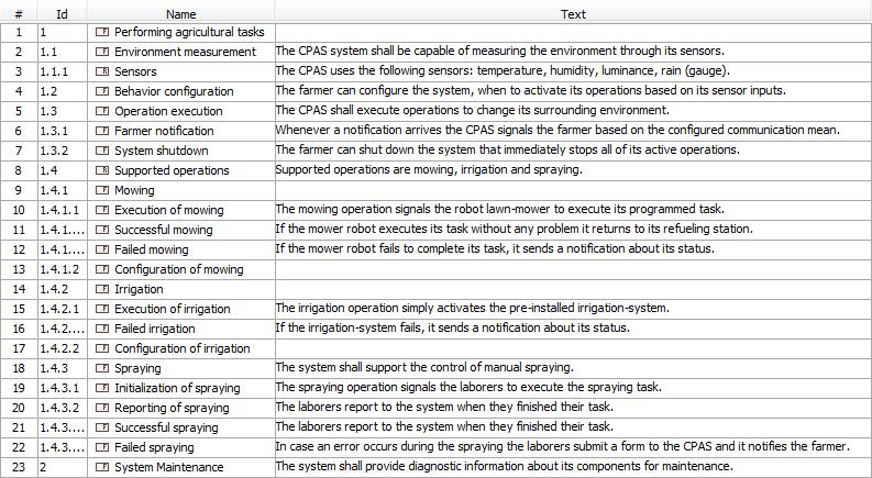
22 Example requirements Design a simple Cyber-physical agricultural system (CPAS), which helps a farmer with his/her everyday life using sensors to measure the environment and react to its changes by using automated operations like irrigation, mowing and spraying. Requirements The CPAS system is capable of measuring the environment through its sensors. The CPAS uses the following sensors: temperature, humidity, luminance, rain. The CPAS can execute operations to change its surrounding environment. These operations can be mowing, irrigation and spraying. The mowing operation signals the robot mower to execute its programmed task. If the mower robot executes its task without any problem it returns to its refueling station. If the mower robot fails to complete its task, it sends a notification about its status 22
23 Example requirements (con t) The irrigation operation simply activates the pre-installed irrigationsystem. If the irrigation-system fails, it sends a notification about its status. Whenever a notification arrives the CPAS signals the farmer based on the configured communication mean. The spraying operation signals the laborers to execute the spraying task. The laborers report to the CPAS when they finished their task. In case an error occurs during the spraying the laborers submit a form to the CPAS and it notifies the farmer. The farmer can configure the system, when to activate its operations based on its sensor inputs. The farmer can shut down the CPAS system that immediately stops all of its active operations. The system shall provide diagnostic information about its components for maintenance. 23
24 Modeling Textual Requirements Context of the Modeling Aspect Sample Requirements (Cyber-physical Agricultural System) Modeling Elements & Notation Summary


25 Example Top Level Requirements Name Id Text Requirement Requirement decomposition 25
26 Example Further Decomposed 26
27 Example Full Hierarchy 27
28 Requirements Table 28
29 Requirements Trace Relations Refine o Depicts a model element that clarifies a requirement o Typically a use case or a behavior Satisfy o Depicts a design or implementation model element that satisfies the requirement Verify o Used to depict a test case that is used to verify a requirement Derive o Used when a requirement is derived from another requirement based on analysis o Typically at the next level of the system hierarchy Copy o Supports reuse by copying requirements to other namespaces o Master-slave relation between requirements Trace o General trace relationship o Between requirement and any other model element 29


30 Example refine relationship Direct notation Compartment notation Callout notation 30
31 Example trace relationships 31
32 Requirements Relations in Table 32
33 Modeling Textual Requirements Context of the Modeling Aspect Sample Requirements (Cyber-physical Agricultural System) Modeling Elements & Notation Summary
34 Summary Goal o Bridge the gap between textual requirements and requirement and design models Handles textual req.s as model elements Provides support for requirements traceability Modeling aspect o What are the main requirements formulated textually and what are their hierarchy? Relation of requirements to other aspects o Refined by model elements (e.g. use case, activity) o Satisfied by blocks o Verified by test cases 34
35 Modeling Requirements with Use Cases Context of the Modeling Aspect Elements of Use Case Diagrams by Example Relations between UC elements Summary
36 Use Case Diagrams 36
37 System Modeling Process 37
38 Modeling Aspect Who will use the system and for what? 38
39 Definition of Use Cases Use cases (használati eset) capture the functional requirements of a system UCs describe o the typical interactions o between the users of a system and o the system itself, o by providing a narrative of how a system is used M. Fowler: UML Distilled. 3rd Edition. Addison-Wesley A set of scenarios tied together by a common user goal Its definition comes from o Either directly from the written requirement Verb + Noun (Unique)! o Based on the Requirement diagram + System context definition refinement 39
40 Relations to other aspects Refines textual requirements Can be further refined by behaviors (e.g. activity) 40
41 Modeling Requirements with Use Cases Context of the Modeling Aspect Elements of Use Case Diagrams by Example Relations between UC elements Summary
42 Example requirements Design a simple Cyber-physical agricultural system (CPAS), which helps a farmer with his/her everyday life using sensors to measure the environment and react to its changes by using automated operations like irrigation, mowing and spraying. Requirements o The CPAS system is capable of measuring the environment through its sensors. o The CPAS uses the following sensors: temperature, humidity, luminance, rain. o The CPAS can execute operations to change its surrounding environment. o These operations can be mowing, irrigation and spraying. o The mowing operation signals the robot mower to execute its programmed task. o If the mower robot executes its task without any problem it returns to its refueling station. o If the mower robot fails to complete its task, it sends a notification about its status 42
43 Example requirements (con t) Requirements o The irrigation operation simply activates the pre-installed irrigationsystem. o If the irrigation-system fails, it sends a notification about its status. o Whenever a notification arrives the CPAS signals the farmer based on the configured communication mean. o The spraying operation signals the laborers to execute the spraying task. o The laborers report to the CPAS when they finished their task. o In case an error occurs during the spraying the laborers submit a form to the CPAS and it notifies the farmer. o The farmer can configure the system, when to activate its operations based on its sensor inputs. o The farmer can shut down the CPAS system that immediately stops all of its active operations. o The system shall provide diagnostic information about its components for maintenance. 43

44 Initial set of Activities 44
45 Definition of Actors Actor (aktor) is a role that a user plays with respect to the system. o Primary actor: calls the system to deliver a service o Secondary actor: the system communicates with them while carrying out the service Relationship of UCs and Actors o A single actor may perform many use cases; o A use case may have several actors performing it. One person may act as more than one actor, o Example: The farmer may also act as a laborer who performs the spraying An actor is outside the boundary of the system Its definition comes from o Directly from the written requirements o Based on the System context definition 45
46 (Initial) Collection of Primary Actors 46


47 (Initial) Collection of Secondary Actors Customized representation Could use the UML actor visualization instead! 47
48 Modeling Requirements with Use Cases Context of the Modeling Aspect Elements of Use Case Diagrams by Example Relations between UC elements Summary
49 System-level overview (User) 49


50 Actor System-level overview (User) System boundary Same behavior! Association: actor initiates or participates in interaction 50


51 Generalization of Actors (abstraction) Actor Generalization (Inheritance) Abstraction /refinement 51
")
52 System-level overview (User) 52

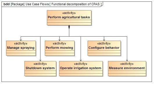
53 How to handle complex functionality? Perform agr. tasks = Measure the environment Configure the system Execute agr. operations Shut down the system 53


54 Refinement with include relation Base UC Included UC Too general description 54 The included UC breaks down the complex core functionality into more elementary steps


55 Generalization of UCs Use Case Generalization (Inheritance) What happens if the irrigation operation fails? 55


56 Extend relationship Base UC Extension UC The extension UC Extends core functionality by handling unusual (exceptional) situation 56
57 Summary: UC Relations Association (Asszociáció) o actor use case o the actor initiates (or participates in) the use of the system Extend (Bővítés) o use case use case o a UC may be extended by another UC (typically solutions for exceptional situations) 57
58 Summary: UC Relations Generalization (Általánosítás) o actor actor o use case use case o a UC or actor is more general / specific than another UC or actor Include (Beszúrás) o use case use case o a complex step is divided into elementary steps o a functionality is used in multiple UCs 58
59 Example: Complete Perform agr. task UC refinement 59
60 Modeling Requirements with Use Cases Context of the Modeling Aspect Elements of Use Case Diagrams by Example Relations between UC elements Summary
61 Goal Summary o Identify top level functional requirements o Identify involved actors Modeling Aspect o Who will use the system and for what? Relations to other aspects o Refines textual requirements o Can be refined by other behaviors (e.g. activity) 61
62 Modeling Flow Based Behavior with Activities Context of the Modeling Aspect Modeling Elements & Notation Semantics of the Model Summary


63 Roots & Relations Flow-sheets and flow-charts are used everywhere... o Brainstorming o Computer algorithms o Business processes 63

64 Activity Diagram 64
65 System Modeling Process 65
66 Modeling Aspect What are the steps in a process? What data flows in the process? 66
67 Objectives Modeling behavior that specifies the transformation of inputs to outputs through a sequence of actions Combined modeling of control flow and data flow in a process or workflow Supporting the definition of high level processes o Elaboration of use cases, i.e. helps to define functional requirements that system components or actors will perform o Providing functional decomposition of the system Supporting the definition of low level activities o Elaboration of behavior executed at given points of the system (e.g. reaction to an event) 67

68 Elaborates use cases 68
69 Modeling Flow Based Behavior with Activities Context of the Modeling Aspect Modeling Elements & Notation Semantics of the Model Summary

70 Control flow Control flow Initial node Fork Action in activity Activity final Join 70
71 Control flow with flow final Flow final 71

72 Fork, join, decision, merge Fork Decision Merge Join 72
73 Action types Primitive action node Send signal node Primitive actions include object access, update and manipulation actions. Send signal data to target. Accept event node Accept events, typically has output pins for received data. Accept time event node Call behavior node Time event corresponds to an expiration of an (implicit) timer. Call other behavior (e.g. another activity). 73


74 Combined control and data flow Pin Object flow Object Parameter of activity 74


75 Object nodes Object node Datastore Central buffer 75

76 Activity decomposition 76


77 Activity Hierarchy (Functional Decomposition) 77
78 Allocating actions Allocation partition Represented block 78
")


79 Modelling Streams (SysML) Pin Discrete flow Activity parameter Discrete flow Flow rate Stream 79

80 Interruptible Activity Region Interruptible activity region Signal reception Interrupting edge 80
81 Modeling Flow Based Behavior with Activities Context of the Modeling Aspect Modeling Elements & Notation Semantics of the Model Summary
82 Data flow and Control flow Combined control and data flow model o semantics dataflow networks Data Flow: data token o Object node Action node An object node is a channel / queue An object may be linked to multiple action nodes Output actions are competing for the data token (i.e. the object) o Type conformance: object type < input type of action Control flow: control token (ordering constraint between two actions) o All predecessor actions should be terminated prior to starting the current action o The current action should terminate prior to starting any of the successor actions 82
83 Semantics: Dataflow Networks o Tokens: control + several data o Channel: object node Node A Node B Stores the tokens o Node: action node Processing tokens o Edges: Channel (control) Channel (data) Flow of tokens weights: how many tokens are in the flow at a time? Control token 2 Data tokens o Firing rule: Behaviour of a node Node C
84 Semantics: Dataflow Networks Firing rule (cont.): o precondition: input tokens + current state o postcondition output tokens + new state IN1 IN2 Node A OUT1 OUT2
85 Semantics: Dataflow Networks Firing rule (cont.): o precondition: input tokens + current state o postcondition output tokens + new state Execution of a firing: o Is there token on all inputs with Right amount? Right type? IN1 Node A IN2 OUT1 OUT2
86 Semantics: Dataflow Networks Firing rule (cont.): o precondition: input tokens + current state o postcondition output tokens + new state Execution of a firing: o Is there token on all inputs with Right amount? Right type? o Execution of action IN1 Node A IN2 OUT1 OUT2
87 Semantics: Dataflow Networks Firing rule (cont.): o precondition: input tokens + current state o postcondition output tokens + new state Execution of a firing: o Is there token on all inputs with Right amount? Right type? o Execution of action o Sending the output tokens IN1 OUT1 Node A IN2 OUT2
88 Example: Shutdown system 88
89 Example: Shutdown system 89
90 Example: Shutdown system 90
91 Example: Shutdown system 91
92 Example: Shutdown system 92
93 Example: Shutdown system 93
94 Example: Shutdown system 94
95 Example: Shutdown system 95
96 Example: Shutdown system 96
97 Example: Shutdown system 97
98 Example: Shutdown system 98
99 Example: Shutdown system 99
100 Example: Shutdown system 100
101 Example: Shutdown system 101
102 Example: Shutdown system 102
103 Example: Shutdown system 103
104 Example: Shutdown system 104

105 Example: Shutdown system 105
106 Modeling Flow Based Behavior with Activities Context of the Modeling Aspect Modeling Elements & Notation Semantics of the Model Summary
107 Summary Goal o Model transformation of input to output in processes o Combined modeling of control and data flow Modeling aspect o What are the steps in a process? o What data flows in the process? Relations to other aspects o Refines requirements, use cases and interactions o Allocates activities to blocks o Defines behavior of blocks, operations or in state machines 107
Modeling Requirements, Architectures, Behaviour...
 Modeling Requirements, Architectures, Behaviour... The System Modeling Language (SysML) and the SYSMOD modeling approach Budapest University of Technology and Economics Department of Measurement and Information
Process and data flow modeling
 Process and data flow modeling Vince Molnár Informatikai Rendszertervezés BMEVIMIAC01 Budapest University of Technology and Economics Fault Tolerant Systems Research Group Budapest University of Technology
Ingegneria del Software Corso di Laurea in Informatica per il Management. Introduction to UML
 Ingegneria del Software Corso di Laurea in Informatica per il Management Introduction to UML Davide Rossi Dipartimento di Informatica Università di Bologna Modeling A model is an (abstract) representation
UML Modeling I. Instructor: Yongjie Zheng September 3, CS 490MT/5555 Software Methods and Tools
 UML Modeling I Instructor: Yongjie Zheng September 3, 2015 CS 490MT/5555 Software Methods and Tools Object-Oriented Design: Topics & Skills Rational Unified Process Unified Modeling Languages (UML) Provide
Information systems modeling. Tomasz Kubik
 Information systems modeling Tomasz Kubik OMG specifications adopted by ISO Name Acronym Version ISO documents Business Process Model And Notation BPMN 2.0.1 19510:2013 Common Object Request Broker Architecture
Introduction to Software Engineering. 5. Modeling Objects and Classes
 Introduction to Software Engineering 5. Modeling Objects and Classes Roadmap > UML Overview > Classes, attributes and operations > UML Lines and Arrows > Parameterized Classes, Interfaces and Utilities
Software Engineering
 Software Engineering Object-Oriented Analysis and Design and Modeling with UML Assoc. Prof. Marenglen Biba MSc in Computer Science, UoG-UNYT Foundation Programme 3-1 Material Get the material from http://www.marenglenbiba.net/foundprog/
Event Metamodel and Profile (EMP) Proposed RFP Updated Sept, 2007
 Proposed RFP Updated Sept, 2007") Event Metamodel and Profile (EMP) Proposed RFP Updated Sept, 2007 Robert Covington, CTO 8425 woodfield crossing boulevard suite 345 indianapolis in 46240 317.252.2636 Motivation for this proposed RFP 1.
Event Metamodel and Profile (EMP) Proposed RFP Updated Sept, 2007 Robert Covington, CTO 8425 woodfield crossing boulevard suite 345 indianapolis in 46240 317.252.2636 Motivation for this proposed RFP 1.
UML 2.0 State Machines
 UML 2.0 State Machines Frederic.Mallet@unice.fr Université Nice Sophia Antipolis M1 Formalisms for the functional and temporal analysis With R. de Simone Objectives UML, OMG and MDA Main diagrams in UML
Introduction to SysML
 ALaRI Faculty of Informatics, University of Lugano, Switzerland Introduction to SysML Workshop on UML for SoC and Embedded Systems Design DATE 07 - Nice Friday, April 20 th, 2007 Some questions before
Future Directions for SysML v2 INCOSE IW MBSE Workshop January 28, 2017
 Future Directions for SysML v2 INCOSE IW MBSE Workshop January 28, 2017 Sanford Friedenthal safriedenthal@gmail.com 1/30/2017 Agenda Background System Modeling Environment (SME) SysML v2 Requirements Approach
What's New in UML 2.0
 What's New in UML 2.0 M.W.Richardson Lead Applications Engineer I-Logix UK mrichardson@ilogix.com What is UML? Unified Modeling Language Comprehensive full life-cycle 3 rd Generation modeling language
Software Development. Modular Design and Algorithm Analysis
 Software Development Modular Design and Algorithm Analysis Functional Decomposition Functional Decomposition in computer science, also known as factoring, refers to the process by which a complex problem
MSc programme (induction week) Department of Informatics INTRODUCTION TO UML
 Department of Informatics INTRODUCTION TO UML") MSc programme (induction week) Department of Informatics INTRODUCTION TO UML Some of this material is based on Bernd Bruegge and Allen H. Dutoit (2009) Object-Oriented Software Engineering: Using UML,
MSc programme (induction week) Department of Informatics INTRODUCTION TO UML Some of this material is based on Bernd Bruegge and Allen H. Dutoit (2009) Object-Oriented Software Engineering: Using UML,
Modelling in Enterprise Architecture. MSc Business Information Systems
 Modelling in Enterprise Architecture MSc Business Information Systems Models and Modelling Modelling Describing and Representing all relevant aspects of a domain in a defined language. Result of modelling
Lecture 05 ( ) High-Level Design with SysML. Systeme hoher Qualität und Sicherheit Universität Bremen WS 2015/2016
 High-Level Design with SysML. Systeme hoher Qualität und Sicherheit Universität Bremen WS 2015/2016") Systeme hoher Qualität und Sicherheit Universität Bremen WS 2015/2016 Lecture 05 (09-11-2015) High-Level Design with SysML Christoph Lüth Jan Peleska Dieter Hutter Where are we? 01: Concepts of Quality
Systeme hoher Qualität und Sicherheit Universität Bremen WS 2015/2016 Lecture 05 (09-11-2015) High-Level Design with SysML Christoph Lüth Jan Peleska Dieter Hutter Where are we? 01: Concepts of Quality
CISC 322 Software Architecture
 CISC 322 Software Architecture UML - The Unified Modelling Language Nicolas Bettenburg 1 DEFINITION The Unified Modelling Language (UML) is a graphical language for visualizing, specifying, constructing,
Software Service Engineering
 Software Service Engineering Lecture 4: Unified Modeling Language Doctor Guangyu Gao Some contents and notes selected from Fowler, M. UML Distilled, 3rd edition. Addison-Wesley Unified Modeling Language
SysML Past, Present, and Future. J.D. Baker Sparx Systems Ambassador Sparx Systems Pty Ltd
 SysML Past, Present, and Future J.D. Baker Sparx Systems Ambassador Sparx Systems Pty Ltd A Specification Produced by the OMG Process SysML 1.0 SysML 1.1 Etc. RFI optional Issued by Task Forces RFI responses
NOTICE. (Formulated under the cognizance of the CTA R7 Home Networks Committee.)
") CTA Standard Task Model Description (CE TASK 1.0) CTA-2018 R2016 (Formerly ANSI/) March 2008 NOTICE Consumer Technology Association (CTA) Standards, Bulletins and other technical publications are designed
CTA Standard Task Model Description (CE TASK 1.0) CTA-2018 R2016 (Formerly ANSI/) March 2008 NOTICE Consumer Technology Association (CTA) Standards, Bulletins and other technical publications are designed
Contents Contents 1 Introduction Entity Types... 37
 1 Introduction...1 1.1 Functions of an Information System...1 1.1.1 The Memory Function...3 1.1.2 The Informative Function...4 1.1.3 The Active Function...6 1.1.4 Examples of Information Systems...7 1.2
OMG Systems Modeling Language Tutorial May, 2012
 OMG Systems Modeling Language Tutorial May, 2012 Giuseppe Scanniello Giuseppina Casalaro System Engineering Overview System Engineering (SE) is a discipline to deal with complex system realised through
Oral Questions. Unit-1 Concepts. Oral Question/Assignment/Gate Question with Answer
 Unit-1 Concepts Oral Question/Assignment/Gate Question with Answer The Meta-Object Facility (MOF) is an Object Management Group (OMG) standard for model-driven engineering Object Management Group (OMG)
INTRODUCTION TO UNIFIED MODELING MODEL (UML) & DFD. Slides by: Shree Jaswal
 & DFD. Slides by: Shree Jaswal") INTRODUCTION TO UNIFIED MODELING MODEL (UML) & DFD Slides by: Shree Jaswal What is UML? 2 It is a standard graphical language for modeling object oriented software. It was developed in mid 90 s by collaborative
INTRODUCTION TO UNIFIED MODELING MODEL (UML) & DFD Slides by: Shree Jaswal What is UML? 2 It is a standard graphical language for modeling object oriented software. It was developed in mid 90 s by collaborative
TDL. bridging the gap between specifications and testing. Dr. Gusztáv Adamis Dr. GyÖrgy réthy Ericsson Hungary Test Solutions and Competence Center
 TDL bridging the gap between specifications and testing Dr. Gusztáv Adamis Dr. GyÖrgy réthy Ericsson Hungary Test Solutions and Competence Center Contents Problem definition TDL - the new ETSI test language
JOURNAL OF OBJECT TECHNOLOGY
 JOURNAL OF OBJECT TECHNOLOGY Online at http://www.jot.fm. Published by ETH Zurich, Chair of Software Engineering JOT, 2003 Vol. 2, No. 6, November-December 2003 UML 2 Activity and Action Models Part 3:
Comparative Analysis of Architectural Views Based on UML
 Electronic Notes in Theoretical Computer Science 65 No. 4 (2002) URL: http://www.elsevier.nl/locate/entcs/volume65.html 12 pages Comparative Analysis of Architectural Views Based on UML Lyrene Fernandes
UML part I. UML part I 1/41
 UML part I UML part I 1/41 UML part I 2/41 UML - Unified Modeling Language unified it can be shared among workers modeling it can be used for description of software model language it has defined structure
Unified Modeling Language (UML)
") Unified Modeling Language (UML) Troy Mockenhaupt Chi-Hang ( Alex) Lin Pejman ( PJ ) Yedidsion Overview Definition History Behavior Diagrams Interaction Diagrams Structural Diagrams Tools Effect on Software
Unified Modeling Language (UML) Troy Mockenhaupt Chi-Hang ( Alex) Lin Pejman ( PJ ) Yedidsion Overview Definition History Behavior Diagrams Interaction Diagrams Structural Diagrams Tools Effect on Software
UML 2.5: Specification Simplification
 A division of Data Access Technologies, Inc. UML 2.5: Specification Simplification Presented at the Third Biannual Workshop on Eclipse Open Source Software and OMG Open Specifications Ed Seidewitz Timeline
Component Design. Systems Engineering BSc Course. Budapest University of Technology and Economics Department of Measurement and Information Systems
 Component Design Systems Engineering BSc Course Budapest University of Technology and Economics Department of Measurement and Information Systems Traceability Platform-based systems design Verification
Analyzing Suitability of SysML for System Engineering Applications
 Master Thesis Software Engineering Thesis no: MSE-2007-19 June 2007 Analyzing Suitability of SysML for System Engineering Applications Saleem Zubair Ahmad School of Engineering Blekinge Institute of Technology
An introduction to MOF MetaObject Facility.
 An introduction to MOF MetaObject Facility pierre-alain.muller@irisa.fr About The MetaObject Facility Specification is the foundation of OMG's industry-standard standard environment where models can be
1 Introduction. 1.1 Introduction
 1 Introduction 1.1 Introduction This book introduces and guides you through the use of the Unified Modeling Language (UML) and the Unified Process (both originally devised by Grady Booch, James Rumbaugh
Object-Oriented Software Engineering Practical Software Development using UML and Java
 Object-Oriented Software Engineering Practical Software Development using UML and Java Chapter 5: Modelling with Classes Lecture 5 5.1 What is UML? The Unified Modelling Language is a standard graphical
For 100% Result Oriented IGNOU Coaching and Project Training Call CPD: ,
 Q.1 What is Object Orientation? Explain the concept of class, objects, instance, generalization, and associations. Ans :-- In the past, information systems used to be defined primarily by their functionality:
Sequence Diagram Generation with Model Transformation Technology
 , March 12-14, 2014, Hong Kong Sequence Diagram Generation with Model Transformation Technology Photchana Sawprakhon, Yachai Limpiyakorn Abstract Creating Sequence diagrams with UML tools can be incomplete,
Instructors: Sanford Friedenthal Joseph Wolfrom
 Modeling with SysML Instructors: Sanford Friedenthal sanford.friedenthal@lmco.com Joseph Wolfrom joe.wolfrom@jhuapl.edu Tutorial presented at INCOSE 2010 Symposium, Chicago, IL, July 2010. OMG SysML Specification
SOFTWARE DESIGN COSC 4353 / Dr. Raj Singh
 SOFTWARE DESIGN COSC 4353 / 6353 Dr. Raj Singh UML - History 2 The Unified Modeling Language (UML) is a general purpose modeling language designed to provide a standard way to visualize the design of a
06. Analysis Modeling
 06. Analysis Modeling Division of Computer Science, College of Computing Hanyang University ERICA Campus 1 st Semester 2017 Overview of Analysis Modeling 1 Requirement Analysis 2 Analysis Modeling Approaches
The Unified Modeling Language User Guide
 The Unified Modeling Language User Guide Grady Booch James Rumbaugh Ivar Jacobson Rational Software Corporation TT ADDISON-WESLEY Boston San Francisco New York Toronto Montreal London Munich Paris Madrid
SE 1: Software Requirements Specification and Analysis
 SE 1: Software Requirements Specification and Analysis Lecture 4: Basic Notations Nancy Day, Davor Svetinović http://www.student.cs.uwaterloo.ca/ cs445/winter2006 uw.cs.cs445 U Waterloo SE1 (Winter 2006)
Exercise Unit 2: Modeling Paradigms - RT-UML. UML: The Unified Modeling Language. Statecharts. RT-UML in AnyLogic
 Exercise Unit 2: Modeling Paradigms - RT-UML UML: The Unified Modeling Language Statecharts RT-UML in AnyLogic Simulation and Modeling I Modeling with RT-UML 1 RT-UML: UML Unified Modeling Language a mix
Enterprise Architect. User Guide Series. SysML Models. Author: Sparx Systems. Date: 30/06/2017. Version: 1.0 CREATED WITH
 Enterprise Architect User Guide Series SysML Models Author: Sparx Systems Date: 30/06/2017 Version: 1.0 CREATED WITH Table of Contents Systems Engineering 3 Systems Modeling Language (SysML) 8 SysML Activity
Model Driven Development Unified Modeling Language (UML)
") Model Driven Development Unified Modeling Language (UML) An Overview UML UML is a modeling notation standardized by OMG (proposal 1997, ver.1.1 in 1998, ver. 2.0 in 2004) now in 2.4.1 mature based on notations
Model Driven Development Unified Modeling Language (UML) An Overview UML UML is a modeling notation standardized by OMG (proposal 1997, ver.1.1 in 1998, ver. 2.0 in 2004) now in 2.4.1 mature based on notations
From Analysis to Design. LTOOD/OOAD Verified Software Systems
 From Analysis to Design 1 Use Cases: Notation Overview Actor Use case System X System boundary UCBase «extend» UCExt Actor A UCVar1 UCVar2 Extending case Generalization «include» Actor B UCIncl Included
Génie Logiciel Avancé - Advanced Software Engineering A Brief Revision of UML
 L3 Mention Informatique Parcours Informatique et MIAGE Génie Logiciel Avancé - Advanced Software Engineering A Brief Revision of UML Burkhart Wolff wolff@lri.fr Plan of the Chapter " The UML notation is
Business Process Model and Notation (BPMN)
") Business Process Model and Notation (BPMN) Daniel Brookshier, Distinguished Fellow, No Magic Inc. 1 BPMN Introduction n BPMN 2.0 is an international standard for business process modeling. n Developed
Business Process Model and Notation (BPMN) Daniel Brookshier, Distinguished Fellow, No Magic Inc. 1 BPMN Introduction n BPMN 2.0 is an international standard for business process modeling. n Developed
CISC836: Models in Software Development: Methods, Techniques and Tools
 CISC836: Models in Software Development: Methods, Techniques and Tools Topic 4: Code Generation with EMF Meta modeling Languages for meta models: Ecore Using EMF and Ecoreto define a data model Using EMF
Process Modeling Using UML
 CHAPTER 5 Process Modeling Using UML GREGOR ENGELS, ALEXANDER FÖRSTER, REIKO HECKEL, and SEBASTIAN THÖNE 5.1 INTRODUCTION The Unified Modeling Language (UML) 1 is a visual, object-oriented, and multipurpose
Requirement Model for Mechanical, Electrical and Software Integrated Products Using SysML
 956 Requirement Model for Mechanical, Electrical and Software Integrated Products Using SysML Tadashi Gotoh 1, Takao Eguchi 1, Tsuyoshi Koga 2, Kazuhiro Aoyama 3 1 IBM Japan, Ltd., 19-21 Nihonbashi Hakozaki-cho,
Chapter : Analysis Modeling
 Chapter : Analysis Modeling Requirements Analysis Requirements analysis Specifies software s operational characteristics Indicates software's interface with other system elements Establishes constraints
Best Practices for Model-Based Systems Engineering
 Seminar / Workshop Best Practices for Model-Based Systems Engineering Hans-Peter Hoffmann, Ph.D. Chief Systems Methodologist, IBM Rational Software hoffmape@us.ibm.com Overview Successfully delivering
Object-Oriented Design
 Object-Oriented Design Lecturer: Raman Ramsin Lecture 10: Analysis Packages 1 Analysis Workflow: Packages The analysis workflow consists of the following activities: Architectural analysis Analyze a use
Computation Independent Model (CIM): Platform Independent Model (PIM): Platform Specific Model (PSM): Implementation Specific Model (ISM):
: Platform Independent Model (PIM): Platform Specific Model (PSM): Implementation Specific Model (ISM):") viii Preface The software industry has evolved to tackle new approaches aligned with the Internet, object-orientation, distributed components and new platforms. However, the majority of the large information
viii Preface The software industry has evolved to tackle new approaches aligned with the Internet, object-orientation, distributed components and new platforms. However, the majority of the large information
Lecture 4: Goals and Scenarios. System context. Usage facet. IT system facet. Core activities. Negotiation. Requirements artefacts
 Lecture 4: Goals and Scenarios Stakeholders Identifying the problem owners Goals Identifying the success criteria Scenarios Identifying how it works 1 System context Subject facet Usage facet IT system
Model Querying with Graphical Notation of QVT Relations
 Model Querying with Graphical Notation of QVT Relations Dan LI, Xiaoshan LI Faculty of Science and Technology, University of Macau Volker Stolz University of Oslo, Norway Agenda! Motivation! QVT Relations
Index. Add Diagram > Sequence Diagram command,
 Quatrani.book Page 183 Monday, May 8, 2006 11:56 AM Index A abstraction, 3 actions completing before processing, 54 55 data flowing through, 53 passing control between, 51 performing, 155 157 as round-cornered
02291: System Integration
 02291: System Integration Hubert Baumeister hub@imm.dtu.dk Spring 2012 Contents 1 General Information 1 2 Overview 3 3 Introduction to UML 11 4 Summary 16 1 General Information System Integration Type
The Unified Modeling Language (UML)
") The Unified Modeling Language (UML) A Very Distilled Introduction to The Unified Modeling Language (UML). A quick introduction to UML is given. Thereafter, the surface of class and activity diagrams and
The Unified Modeling Language (UML) A Very Distilled Introduction to The Unified Modeling Language (UML). A quick introduction to UML is given. Thereafter, the surface of class and activity diagrams and
JOURNAL OF OBJECT TECHNOLOGY
 JOURNAL OF OBJECT TECHNOLOGY Online at http://www.jot.fm. Published by ETH Zurich, Chair of Software Engineering JOT, 2004 Vol. 3, No. 1, January-February 2004 UML 2 Activity and Action Models Part 4:
Week 9 Implementation
 Week 9 Implementation Dr. Eliane l. Bodanese What is more important From a software engineering perspective: Good Gui? does what customer wants maintainable, extensible, reusable Commented Code? how is
JOURNAL OF OBJECT TECHNOLOGY
 JOURNAL OF OBJECT TECHNOLOGY Online at http://www.jot.fm. Published by ETH Zurich, Chair of Software Engineering JOT, 2004 Vol. 3, No. 7, July-August 2004 UML 2 Activity and Action Models Part 5: Partitions
SE Assignment III. 1. List and explain primitive symbols used for constructing DFDs. Illustrate the use of these symbols with the help of an example.
 SE Assignment III 1. List and explain primitive symbols used for constructing DFDs. Illustrate the use of these symbols with the help of an example. There are essentially 5 different types of symbols used
Introduction to Software Engineering. ECSE-321 Unit 9 Architectural Design Approaches
 Introduction to Software Engineering ECSE-321 Unit 9 Architectural Design Approaches Requirement Elicitation Analysis (Software Product Design) Architectural Design Detailed Design Architectural Design
Activities Radovan Cervenka
 Unified Modeling Language Activities Radovan Cervenka Activity Model Specification of an algorithmic behavior. Used to represent control flow and object flow models. Executing activity (of on object) is
Index. brief description section (Use Case Specification documents), 138 Browser window (Rational Rose), 257 Business Rules document, 212
, 138 Browser window (Rational Rose), 257 Business Rules document, 212") Index A abstract requirements, 10 activity diagram section (Use Case -144 actors identifying, 130-131 relationships, generalization between, 137 use cases, 133-135 Actual completion date attribute actual
Index A abstract requirements, 10 activity diagram section (Use Case -144 actors identifying, 130-131 relationships, generalization between, 137 use cases, 133-135 Actual completion date attribute actual
Course "Softwaretechnik" Book Chapter 2 Modeling with UML
 Course "Softwaretechnik" Book Chapter 2 Modeling with UML Lutz Prechelt, Bernd Bruegge, Allen H. Dutoit Freie Universität Berlin, Institut für Informatik http://www.inf.fu-berlin.de/inst/ag-se/ Modeling,
Lecture 8: Goals and Scenarios. Pohl K., Requirements Engineering: Fundamentals, Principles, and Techniques, Springer, 2010, 814p.
 Lecture 8: Goals and Scenarios Pohl K., Requirements Engineering: Fundamentals, Principles, and Techniques, Springer, 2010, 814p. 2 Documenting Goals 3 Documenting Goals 1. Each goal must have a unique
SysML and UML 2 Support for Activity Modeling*
 SysML and UML 2 Support for Activity Modeling* Conrad Bock Regular Paper U.S. National Institute of Standards and Technology, 100 Bureau Drive, Stop 8263, Gaithersburg, MD 20899-8263 SysML AND UML 2 SUPPORT
Introduction to Software Engineering. 5. Modeling Objects and Classes
 Introduction to Software Engineering 5. Modeling Objects and Classes Roadmap > UML Overview > Classes, attributes and operations > UML Lines and Arrows > Parameterized Classes, Interfaces and Utilities
UML big picture. Perdita Stevens. School of Informatics University of Edinburgh
 UML big picture Perdita Stevens School of Informatics University of Edinburgh Plan Whence UML? Parts of UML How it all fits together UML as a language Consistency: what does it mean, do we need it? Defining
UMLEmb: UML for Embedded Systems. I. Introduction. Ludovic Apvrille Eurecom, office 470
 UMLEmb: UML for Embedded Systems I. Introduction Ludovic Apvrille ludovic.apvrille@telecom-paristech.fr Eurecom, office 470 http://soc.eurecom.fr/umlemb/ @UMLEmb Eurecom Goals System specification (includes
2.0.3 attributes: A named property of a class that describes the range of values that the class or its instances (i.e., objects) may hold.
 may hold.") T0/04-023 revision 2 Date: September 06, 2005 To: T0 Committee (SCSI) From: George Penokie (IBM/Tivoli) Subject: SAM-4: Converting to UML part Overview The current SCSI architecture follows no particular
T0/04-023 revision 2 Date: September 06, 2005 To: T0 Committee (SCSI) From: George Penokie (IBM/Tivoli) Subject: SAM-4: Converting to UML part Overview The current SCSI architecture follows no particular
How and Why to Use the Unified Modeling Language. among software components, architectural-based
 This article addresses the Unified Modeling Language and its purpose, constructs, and application to defense software development applications. The Unified Modeling Language (UML) is a notation that can
Approaches of using UML for Embedded System Design
 Approaches of using UML for Embedded System Design Sudeep D. Thepade Lecturer, Dept. of Information Technology, Thadomal Shahani Engg. College, Bandra, Mumbai sudeepthepade@gmail.com Abstract New approaches
Software Engineering
 Software Engineering A systematic approach to the analysis, design, implementation and maintenance of software. Software Development Method by Jan Pettersen Nytun, page 1 Software Engineering Methods Most
Object Oriented Modeling
 Overview UML Unified Modeling Language What is Modeling? What is UML? A brief history of UML Understanding the basics of UML UML diagrams UML Modeling tools 2 Modeling Object Oriented Modeling Describing
Course 3 7 March
 Course 3 7 March adiftene@info.uaic.ro 1 From Courses 1, 2 Modeling Modeling Languages Graphic Languages UML History UML Definition UML Diagram Types UML Use Case Diagram Actors Use Case UML Class Diagrams
Process Modelling. Fault Tolerant Systems Research Group. Budapest University of Technology and Economics
 Process Modelling Budapest University of Technology and Economics Fault Tolerant Systems Research Group Budapest University of Technology and Economics Department of Measurement and Information Systems
Unified Modeling Language I.
 Unified Modeling Language I. Software engineering Szoftvertechnológia Dr. Balázs Simon BME, IIT Outline Software engineering Modeling Unified Modeling Language (UML) UML Diagrams: Use Case Diagram Activity
An Information Model for High-Integrity Real Time Systems
 An Information Model for High-Integrity Real Time Systems Alek Radjenovic, Richard Paige, Philippa Conmy, Malcolm Wallace, and John McDermid High-Integrity Systems Group, Department of Computer Science,
SysML, It s Coming Are You Prepared?
 SysML, It s Coming Are You Prepared? Presentation for George Mason University Shana L. Lloyd The Aerospace Corporation 703-324-8877 Shana.l.lloyd@aero.org January 31, 07 1 Outline Introduction SysML Background
Software Architecture in Action. Flavio Oquendo, Jair C Leite, Thais Batista
 Software Architecture in Action Flavio Oquendo, Jair C Leite, Thais Batista Motivation 2 n In this book you can learn the main software architecture concepts and practices. n We use an architecture description
Object-Oriented Software Engineering Practical Software Development using UML and Java. Chapter 5: Modelling with Classes
 Object-Oriented Software Engineering Practical Software Development using UML and Java Chapter 5: Modelling with Classes 5.1 What is UML? The Unified Modelling Language is a standard graphical language
Chapter 4. Capturing the Requirements. 4th Edition. Shari L. Pfleeger Joanne M. Atlee
 Chapter 4 Capturing the Requirements Shari L. Pfleeger Joanne M. Atlee 4th Edition It is important to have standard notations for modeling, documenting, and communicating decisions Modeling helps us to
Unified Modeling Language - UML
 Eshcar Hillel Unified Modeling Language - UML A specification language for object modeling Industry-standard Simplifies the complex process of design Create a "blueprint" for construction Visualize the
Index. : (colon), 80 <<>> (guillemets), 34, 56
, 80 <<>> (guillemets), 34, 56") : (colon), 80 (guillemets), 34, 56 A Abstraction, 3 Acronyms, 54 Action field, 140 Actions tab, 140 ActiveX controls (Microsoft), 163 Activities. See also Activity diagrams basic description of, 241
: (colon), 80 (guillemets), 34, 56 A Abstraction, 3 Acronyms, 54 Action field, 140 Actions tab, 140 ActiveX controls (Microsoft), 163 Activities. See also Activity diagrams basic description of, 241
UML 2.0 UML 2.0. Scott Uk-Jin Lee. Division of Computer Science, College of Computing Hanyang University ERICA Campus
 UML 2.0 Division of Computer Science, College of Computing Hanyang University ERICA Campus Introduction to UML 2.0 UML Unified Modeling Language Visual language for specifying, constructing and documenting
Metamodeling. Janos Sztipanovits ISIS, Vanderbilt University
 Metamodeling Janos ISIS, Vanderbilt University janos.sztipanovits@vanderbilt.edusztipanovits@vanderbilt edu Content Overview of Metamodeling Abstract Syntax Metamodeling Concepts Metamodeling languages
Finite State Machines and Statecharts
 Finite State Machines and Statecharts Hassan Gomaa Dept of Information & Software Engineering George Mason University Reference: H. Gomaa, Chapter 10 - Designing Concurrent, Distributed, and Real-Time
USING TRANSFORMATIONS TO INTEGRATE TASK MODELS IN
 USING TRANSFORMATIONS TO INTEGRATE TASK MODELS IN THE UML Position Paper to the WTUML: Workshop on Transformations in UML ETAPS 2001 European Joint Conference on Theory and Practice of Software Nuno Jardim
USE CASE BASED REQUIREMENTS VERIFICATION
 USE CASE BASED REQUIREMENTS VERIFICATION Verifying the consistency between use cases and assertions Stéphane S. Somé, Divya K. Nair School of Information Technology and Engineering (SITE), University of
Darshan Institute of Engineering & Technology for Diploma Studies
 REQUIREMENTS GATHERING AND ANALYSIS The analyst starts requirement gathering activity by collecting all information that could be useful to develop system. In practice it is very difficult to gather all
UNIT-I Introduction of Object Oriented Modeling
 UNIT-I Introduction of Object Oriented Modeling - Prasad Mahale Object Oriented Modeling and Reference Books: Design 1. Grady Booch, James Rumbaugh, Ivar Jacobson Unified Modeling Language User Guide,
Software Engineering Fall 2015 (CSC 4350/6350) TR. 5:30 pm 7:15 pm. Rao Casturi 09/17/2015
 TR. 5:30 pm 7:15 pm. Rao Casturi 09/17/2015") Software Engineering Fall 2015 (CSC 4350/6350) TR. 5:30 pm 7:15 pm Rao Casturi 09/17/2015 http://cs.gsu.edu/~ncasturi1 Requirement Elicitation 2 Requirement Engineering First step for understanding the
Software Engineering Fall 2015 (CSC 4350/6350) TR. 5:30 pm 7:15 pm Rao Casturi 09/17/2015 http://cs.gsu.edu/~ncasturi1 Requirement Elicitation 2 Requirement Engineering First step for understanding the
UML EXTENSIONS FOR MODELING REAL-TIME AND EMBEDDED SYSTEMS
 The International Workshop on Discrete-Event System Design, DESDes 01, June 27 29, 2001; Przytok near Zielona Gora, Poland UML EXTENSIONS FOR MODELING REAL-TIME AND EMBEDDED SYSTEMS Sławomir SZOSTAK 1,
Lecture 9 Requirements Engineering II
 Lecture 9 Requirements Engineering II Software Engineering ITCS 3155 Fall 2008 Dr. Jamie Payton Department of Computer Science University of North Carolina at Charlotte September 23, 2008 Announcements
Chapter 10. Object-Oriented Analysis and Modeling Using the UML. McGraw-Hill/Irwin
 Chapter 10 Object-Oriented Analysis and Modeling Using the UML McGraw-Hill/Irwin Copyright 2007 by The McGraw-Hill Companies, Inc. All rights reserved. Objectives 10-2 Define object modeling and explain
02291: System Integration
 02291: System Integration Introduction to UML Hubert Baumeister huba@dtu.dk DTU Compute Technical University of Denmark Spring 2019 What is the UML? Unified Modelling Language (UML) Family of graphical