Best Practices for Model-Based Systems Engineering
|
|
|
- Collin Ellis
- 5 years ago
- Views:
Transcription
1 Seminar / Workshop Best Practices for Model-Based Systems Engineering Hans-Peter Hoffmann, Ph.D. Chief Systems Methodologist, IBM Rational Software hoffmape@us.ibm.com

2 Overview Successfully delivering complex systems requires the development of optimal designs on time, within budget and meeting quality standards. In this hands on workshop, learn how to apply IBM Rational's Best Practices for Model-based Systems Engineeringto help improve system architecture from the start. It will be shown how modeling and model execution supports the different development phases. The role of testing, as well as requirements traceability throughout the development process, will be addressed. After an introduction to the fundamentals of the model-based systems engineering approach (essential UML/SysML artifacts for systems engineering, service request-driven system modeling approach), the model-based systems engineering workflow and the generation of associated work products will be demonstrated by means of a simple example (Security System). 1 Introduction Fig.1-1 shows the Rational Integrated Systems / Embedded Software Development Process Harmony by means of the classic V diagram. The left leg of the V describes the top-down design flow, while the right hand side shows the bottom-up integration phases from unit test to the final system acceptance. Using the notation of statecharts, the impact of a change request on the workflow is visualized by the high-level interrupt. Whenever a change request occurs, the process will restart at the requirements analysis phase. Fig.1-1 Rational Integrated Systems/ Embedded Development Process Harmony
3 The Harmony process consists of two closely coupled sub-processes - Harmony for Systems Engineering and - Harmony for Embedded Real Time Development The systems engineering workflow is iterative with incremental cycles through the phases requirements analysis, system functional analysis and design synthesis. The increments are use case based. The software engineering workflow is characterized by the iterative incremental cycles through the software analysis and design phase, the implementation phase, and the different levels of integration and testing. Regarding the systems engineering and implementation iterations, it should be noted, that the analysis iterations continue through implementation and testing, thus providing something demonstrable with each iteration. It is important to note the creation and reuse of requirements related test scenarios all along the topdown design path. These scenarios are also used to assist the bottom-up integration and test phases and, in the case of system changes, regression test cycles. The Harmony process supports Model-Driven Development (MDD). In a model-driven development, the model is the central work product of the development processes, encompassing both analysis and design. Each development phase is supported by a specific type of model. Models that support the requirements analysis phase are - the Requirement Models and - the System Use Cases Model. A requirement model visualizes the taxonomy of requirements. The system use cases model groups requirements into system use cases. Neither of these models is executable. In the system functional analysis phase the focus is on the translation of the functional requirements into a coherent description of system functions (operations). Each use case is translated into an executable model and the underlying system requirements verified through model execution. There are two types of executable models supporting the design synthesis phase: - Architectural Analysis Model(s) and - System Architecture Model The objective of the architectural analysis model(s) - also referred to as Trade Study Model(s) - is to elaborate an architectural concept for the implementation of the identified operations e.g. through a parametric analysis. The system architecture model captures the allocation of the system operations to the system architecture that was elaborated in the previous architectural analysis phase. The correctness and completeness of the system architecture model is verified through model execution. Once the model is verified, the architectural design may be analyzed with regard to performance and safety requirements. The analysis may include Failure Modes Effects Analysis (FMEA), and Mission Criticality Analysis. The baselined system architecture model defines the hand-off to the subsequent HW/SW development.

4 Model-driven software development is supported by the Software Implementation Model. This model is the basis for - either manual or automatic - code generation. An essential element of the model-driven development process is the Model/Requirements Repository. It contains the configuration controlled knowledge of the system under development, i.e. - Requirements documentation - Requirements traceability - Design documentation and - Test definitions 2 Fundamentals of model-based systems engineering 2.1 Essential SysML artifacts Fig shows the SysML diagrams that are used to capture the structural system view. Fig SysML Diagrams Capturing the Structural System View Block Definition Diagram:: Defines the structural elements (Blocks) of the system and their relationship. Internal Block Diagram: Defines the realization of the system structure. Parametric Diagram: Defines the parametric relationship between system properties.
 Use Case Diagram: Defines the system scope and groups requirements into Use Cases ( Table of Contents of SuD User Manual")
5 Fig shows the SysML diagrams that are used to capture the system behavior. Note: It is recommended to follow the outlined sequence of the system behavior elaboration. Fig SysML Diagrams Capturing the System Behavior (Example: Use Case Behavior) Use Case Diagram: Defines the system scope and groups requirements into Use Cases ( Table of Contents of SuD User Manual ). Activity Diagram: Shows at the functional analysis level the functional flows through the use case ( Storyboard ). At the architectural design level, it shows the allocation of decisions and operations across the system/subsystem architecture. Sequence Diagram: Shows at the functional analysis level the allocation of operations and the message interactions between use cases and associated actors. At the architectural design level, it shows the allocation of operations and the message interactions between systems, subsystems, subsystem components, and actors. Statechart Diagram: Aggregates the information from the activity diagram (functional flow) and the sequence diagrams (actor interactions). It puts this information into the context of system states and adds to it the system behavior due to external stimuli of different priority.

6 2.2 Service request-driven modeling approach In the Service Request-Driven Approach, the communication between blocks is based on asynchronous messages ( service requests ) via UML/SysML Standard Ports. A service request always is followed by an associated provided service at the receiving part either state/mode change or operation. First, the service requests and associated operations have no arguments. At a later stage arguments may be added to the service requests and associated operations as arguments or tags of the relevant service request and associated operation. The approach is performed in four steps: It starts with the definition of the network nodes by means of SysML structure diagrams, using blocks as the basic structure elements. First, these blocks are empty and not linked. In the next step, the communication between the blocks is described in a UML/SysML Sequence Diagram. Note: In the Rhapsody tool the Sequence Diagram may be automatically generated from an underlying Activity Diagram by means of the SE Toolkit. The next step is the allocation of the service requests and operations to respective blocks. Note: In the Rhapsody tool this step is automated through the Auto Realize feature. Based on the allocated service requests, the associated SysML Standard Ports and interfaces now can be defined. Note: In the Rhapsody tool this step is automated by means of the SE-Toolkit


.")
7 3 Task Flow and Work Products in the Model-based SE Approach 3.1 Requirements Analysis Hands-on Exercise In this exercise it will be demonstrated how requirements documented in a Word document - are imported into Rhapsody by means of the Rational Gateway tool. Open the Rhapsody project SecuritySystem_RA. The project structure of this model is the generic Harmony structure automatically generated by means of the SE- Toolkit ( Create Harmony Project ). An essential precondition for this is that the HarmonySE profile was added to the SysML profile. NOTE: The toolkit automatically creates an empty Use Case Diagram(UCD_< project name>).

8 Task 1: Import Requirements 1. Launch Gateway: Right-click SecuritySystem_RA > Rational Rhapsody Gateway > Open 2. In Gateway, select File > Edit Project 3. Browse to the folder Security System Nominal Requirements 4. Drag the folder onto the Gateway project canvas 5. Drag a coverage link from the UML Model to the requirements document. 6. Click OK.


9 Task 2: Add Requirements to Rhapsody 1. In Gateway, select the UML Model document in the Selection pane. 2. On the Gateway Tools menu, select Add high level requirements. 3. In the dialog box, expand the Rhapsody browser structure and select the RequirementsPkg 4. Click OK. 5. Close the Gateway and return to Rhapsody
10 Task 3: Create Use Case Diagram 1. Double-click UCD_SecuritySystem_RA (automatically generated when creating a Harmony project). 2. Use the drawing tool to create the following Use Case Diagram: Task 4: Link Use Cases to System Requirements Use cases are linked to the associated system requirements through a <<trace>> dependency. The creation of this dependency is supported by the SE-Toolkit. 1. In the tools menu select Tools > SE-Toolkit > Modeling Toolbox. In the dialog box select Dependencies, Profile: PredefinedTypes, Stereotype: trace. 2. In the UseCaseDiagramPkg select the use case Uc1ControlEntry. In the dialog box click Set Source 3. In the Security_System_Nominal_Requirements package select requirements SRN01 SRN05. In the dialog box click Set Destination. 4. In the dialog box click Create Dependency with Stereotype.

. - The use case incl.")
11 Task 4 Setup System Functional Analysis The transition from model-based Requirements Analysis to model-based System Functional Analysis is supported through the SE-Toolkit. In the use case diagram UCD_SecuritySystem_RA right-click the use case and select SE-Toolkit > Create System Model From Use Case. The toolkit feature moves the use case associated actors into the ActorPkg. Automatically, the FunctionalAnalysisPkg is populated: - A system block Uc_Uc1ControlEntry is created. - An IBD_Uc1ControEntry is created containing the instances of the actors and the use case block (no links between the parts). - The use case incl. its associated requirements links is moved into the Uc1ControlEntryPkg. In addition, the toolkit created an empty Activity Diagram (Uc1ControlEntryBlackBoxView).
 system and its actors and is the aggregate of all use case blocks interfaces of an iteration increment. This ICD is the basis for the later system-level (black-box) test definition.")
.")
12 3.2 System Functional Analysis Documents created at the end of the System Functional Analysis: The System-Level Interface Control Document (ICD) defines the logical (= functional) interfaces between the (black-box) system and its actors and is the aggregate of all use case blocks interfaces of an iteration increment. This ICD is the basis for the later system-level (black-box) test definition. Hands-on Exercise In this exercise it will be demonstrated how the use case story is translated into an executable use case model. First, the functional flow will be captured in an Activity Diagram. Then the interactions with the environment will be derived via Sequence Diagram(s). Finally, the complete use case behavior will be captured in a Statechart Diagram based on the Activity Diagram and Sequence Diagram(s) information. The underlying requirements then will be verified/validated through model execution. Open the Rhapsody project SecuritySystem This project contains the complete executable model of the use case Uc1ControlEntry based on the nominal security system requirements imported into Rhapsody in the previous Requirements Analysis phase. NOTE: It is highly recommended to extend the behavior w.r.t. the extended security system requirements listed and realized in the Appendix. For the import of the respective requirements into Rhapsody via the Gateway tool please use the Word document Security System Extended Requirements.


13 Task 1: Capture Use Case Functional Flow The location of the use case Activity Diagram is FunctionalAnalysisPkg > Use Cases > Uc1ControlEntry > ActivityViews >Uc1ControlEntryBlackBoxView Double-click NominalUseCase Actions stereotyped <<MessageAction>> describe the reception or transmission of a message. Harmony for Systems Engineering uses a SysML activity pin stereotyped ActorPin to visualize the interaction of an action with the environment. The name of the pin is the name of the associated actor. The arrow in the pin shows the direction of the link. In order to add an ActorPin to an action, right-click the action and select SE-Toolkit > Add Actor Pins.

 Use case scenarios are created from the Activity Diagram by means of the SE-Toolkit. 1.")
14 Optionally extend the nominal flow w.r.t. the extended system requirements listed in the Appendix. NOTE: In this case, the Admin needs to be added as actor to the Use Case Diagram in the RequirementsAnalysisPkg. Once the diagram is updated, right-click the use case and select SE-Toolkit > Create System Model From Use Case. Through this the Admin is added to the ActorPkg. Task 2: Derive Use Case Scenario(s) Use case scenarios are created from the Activity Diagram by means of the SE-Toolkit. 1. In the Activity Diagram window right-click and select SE-Toolkit > Generate Sequence Diagrams. 2. Hold down Ctrl and select in the Activity Diagram a sequence of actions. Alternatively select a single action as the source. In this case the tool will auto-create the sequence until it reaches a condition connector or a sync bar. The user is then given the choice of which path to take. 3. In the dialog box click Set Source 4. In the dialog box select Create Events and then Create New Scenario From Activity Diagram.
15 NOTE: The Interaction Operators and the Operand Separator are added manually. NOTE: Using the SE-Toolkit, automatically - Actions are translated into operations (incl. associated descriptions and tags) and - MessageActions with ActorPins are translated to respective Actor receptions. The generated Sequence Diagram(s) are automatically stored in the Uc1ControlEntryBBScenariosPkg.
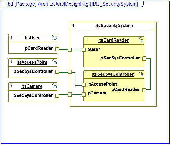
16 Task 3: Create Use Case Model Ports and Interfaces The definition of ports and associated interfaces is automated in Rhapsody by means of the SE-Toolkit feature Create Ports And Interfaces. Pre-condition: All messages and operations in the sequence diagrams are realized. Naming convention for ports: p<targetname> Interface names are referenced to the sender port. Naming convention: i< Sender >_< Receiver > 1. Right-click the package Uc1ControlEntryBBScenariosPkg and select SE-Toolkit > Create Ports And Interfaces. 2. In the browser select FunctionalAnalysisPkg > Uc_Uc1ControlEntry > Internal Block Diagram. Double-click IBD_Uc1_ControlEntry. 3. Manually connect ports.

, and adds to it the event-driven block behavior.")


17 Task 4: Capture Use Case / Actor(s) Behavior in a Statechart Diagram A Statechart Diagram describes the state-based behavior of a block. It aggregates the information from both the activity diagram (functional flow) and the sequence diagrams (interactions with the environment), and adds to it the event-driven block behavior. As the language of statecharts is formally defined, the correctness and completeness of the resulting behavior can be verified through model execution. Basically, a Statechart Diagram is composed of a set of states joined by transitions and various connectors. An event may trigger a transition from one state to another. Actions can be performed on transitions and on state entry/exit State-based behavior of the use case block Uc_Uc1ControlEntry I

.")

18 In order to execute the use case model closed-loop, also the behavior of the actors has to be captured. The Rhapsody SE-Toolkit provides a feature to automatically generate the actor behavior based on the actor s provided/required interface information: In the use case Internal Block Diagram right-click the User block and select Se-Toolkit > Create Test Bench The captures the User behavior in one state using MOORE syntax (= action is state). It includes already the capability to run model execution via Webify. Alternatively, the actor behavior may be captured in a more detailed Statechart Diagram: 1. In the use case Internal Block Diagram right-click the User block and select Class > New Statechart 2. Capture the actor behavior in a statemachine.


19 Task 5: Verify/Validate Use Case Behavior through Model Execution 1. In the toolbar select Window >Close All 2. In the toolbar select Code> Generate/Make/Run 3. Start model execution by clicking the GO button in the animation toolbar 4. In the toolbar select Tools > Animated Sequence Diagram In the FunctionalAnalysisPkg/UciControlEntryBBScenarioPkg select SC1 5. In the toolbar select Tools > Animated Statechart
![6. Select Uc_Uc1ControlEntry[0] 7. In the Uc1ControlEntry Statechart open the Sub-Statechart UnlockingAndLockingAccessPoint by clicking the decomposition icon. 8. Arrange the diagrams.](/docs-images/89/98208968/images/20-0.jpg "You may optimize the layout of each diagram by means of the Zoom to Fit button in the toolbar. 9. Start Webify and run the model execution.")
20 6. Select Uc_Uc1ControlEntry[0] 7. In the Uc1ControlEntry Statechart open the Sub-Statechart UnlockingAndLockingAccessPoint by clicking the decomposition icon. 8. Arrange the diagrams. You may optimize the layout of each diagram by means of the Zoom to Fit button in the toolbar. 9. Start Webify and run the model execution. Use the provided graphical user interface to control the model execution

21 You may interrupt the model execution by clicking the Animation Break button in the animation toolbar or terminate the model execution by clicking the Quit Animation button. Animation Break Quit Animation

22 Once the model execution is terminated, the recorded Sequence Diagram is saved in the Uc1ControlEntryBBScenariosPkg as Animated <Scenario Pattern ID>.
 architecture. The allocation is an iterative process and is typically performed in collaboration with domain experts.")

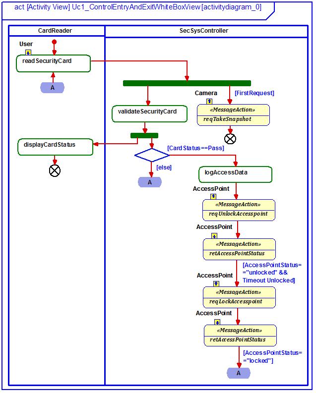
23 3.2 Architectural Design The focus of the architectural design phase is on the allocation of functional requirements and nonfunctional requirements to an architectural structure. This structure may be the result of a previous trade study or a given (legacy) architecture. The allocation is an iterative process and is typically performed in collaboration with domain experts. Architectural design is performed incrementally for each use case of an iteration by transitioning from the black-box view to the white-box view also referred to as use case realization. The task flow is quite similar to the one outlined for the System Functional Analysis. It starts with the definition of the system architectural structure. Based on the chosen design concept the use case block is decomposed into its relevant system architecture parts. The resulting structure is captured in a SysML Block Definition Diagram (BDD) and Internal Block Diagram (IBD). Next, the system-level use case operations are allocated to the relevant subsystems by means of the associated Use Case White-Box Activity Diagram. Essentially, this activity diagram is a copy of the Use Case Black-Box Activity Diagram, partitioned into swim lanes, each representing a block of the system architectural decomposition hierarchy. Based on the chosen design concept, the system-level operations (activities) then are moved into respective block swim lanes. An essential requirement for
24
25 this allocation is that the initial links (control flow) between the activities are maintained. If an action cannot be allocated to a single block, it must be further decomposed. In this case, the sub-operations need to be linked to the parent operation through a respective dependency. An action/operation may also be allocated to more than one block, e.g. in order to meet fault tolerance requirements (architectural redundancy). In this case, the relevant operation/action is copied into the respective block swim lane and integrated into the functional flow. This process may be repeated iteratively for each level of architectural decomposition, resulting in a nested Use Case White-Box Activity Diagram. White-box activity diagrams provide an initial estimate of the resulting load on respective communication channels, as links that cross a swim lane correspond to interfaces. Dependent on the hand-off to the subsequent development, the subsystem block(s) - and associated white-box activity diagram may need to be further decomposed. At the lowest level, the functional allocation may address which operation should be implemented in hardware and which should be implemented in software. From the final Use Case White-Box Diagram, associated White-Box Sequence Diagrams are derived. As outlined previously, these sequence diagrams are the basis from which ports and interfaces of the blocks at the lowest level of the system architecture are derived. Once system-level operations are allocated to the relevant blocks at the lowest level of the architectural decomposition and associated interfaces are defined, the individual state-based behavior is captured in a Statechart Diagram. The leaf-block behavior as well as the collaboration of the decomposed subsystems then is verified through model execution. The last step in the use case realization task flow is the allocation of non-functional requirements to the relevant part(s) and/or operations (e.g. time budgeting). Respective trace links need to be established. The final task in the design synthesis phase is the creation/update of the Integrated System Architecture Model. This model is the aggregate of the realized use case models. The use cases collaboration as well as the correctness and completeness of the integrated system architecture model may be verified through model execution.
Enterprise Architect Training Courses
 On-site training from as little as 135 per delegate per day! Enterprise Architect Training Courses Tassc trainers are expert practitioners in Enterprise Architect with over 10 years experience in object
Lab 8: Streams & Components
 Lab 8: Streams & Components Objectives After completing this lab, you will be able to: Create a new stream Create components in the stream Restrict Access to those components to specific teams, individuals
Objectives. Explain the purpose and objectives of objectoriented. Develop design class diagrams
 Objectives Explain the purpose and objectives of objectoriented design Develop design class diagrams Develop interaction diagrams based on the principles of object responsibility and use case controllers
Enterprise Architect. User Guide Series. Maintenance. Author: Sparx Systems. Date: 30/06/2017. Version: 1.0 CREATED WITH
 Enterprise Architect User Guide Series Maintenance Author: Sparx Systems Date: 30/06/2017 Version: 1.0 CREATED WITH Table of Contents Maintenance 3 Working on Maintenance Items 5 Create Maintenance Items
Enterprise Architect. User Guide Series. Maintenance
 Enterprise Architect User Guide Series Maintenance In Sparx Systems Enterprise Architect, Maintenance items (such as defects, tasks and events) are managed as element properties. Change and Issue elements
Enterprise Architect. User Guide Series. SysML Models. Author: Sparx Systems. Date: 30/06/2017. Version: 1.0 CREATED WITH
 Enterprise Architect User Guide Series SysML Models Author: Sparx Systems Date: 30/06/2017 Version: 1.0 CREATED WITH Table of Contents Systems Engineering 3 Systems Modeling Language (SysML) 8 SysML Activity
OBJECT ORIENTED DESIGN with the Unified Process. Use Case Realization
 OBJECT ORIENTED DESIGN with the Unified Process Use Case Realization 2016 Software Engineering 2 (Zoom-Into Design) Requirement Requirement Specification (Functional & Non- Functional) analysis Requirement
Enterprise Architect. User Guide Series. Domain Models
 Enterprise Architect User Guide Series Domain Models What support for modeling domains? Sparx Systems Enterprise Architect supports a range of modeling languages, technologies and methods that can be used
Component Design. Systems Engineering BSc Course. Budapest University of Technology and Economics Department of Measurement and Information Systems
 Component Design Systems Engineering BSc Course Budapest University of Technology and Economics Department of Measurement and Information Systems Traceability Platform-based systems design Verification
OBJECT ORIENTED DESIGN with the Unified Process. Use Case Realization
 OBJECT ORIENTED DESIGN with the Unified Process Use Case Realization Objectives Explain the purpose and objectives of objectoriented design Develop design class diagrams Develop detailed sequence diagrams
Enterprise Architect. User Guide Series. Testpoints. Author: Sparx Systems. Date: 30/06/2017. Version: 1.0 CREATED WITH
 Enterprise Architect User Guide Series Testpoints Author: Sparx Systems Date: 30/06/2017 Version: 1.0 CREATED WITH Table of Contents Testpoints 3 Test Domain Diagram 7 Test Cut 9 Test Set 10 Test Suite
OMG Systems Modeling Language Tutorial May, 2012
 OMG Systems Modeling Language Tutorial May, 2012 Giuseppe Scanniello Giuseppina Casalaro System Engineering Overview System Engineering (SE) is a discipline to deal with complex system realised through
Enterprise Architect. User Guide Series. SysML Models. Author: Sparx Systems Date: 26/07/2018 Version: 1.0 CREATED WITH
 Enterprise Architect User Guide Series SysML Models Author: Sparx Systems Date: 26/07/2018 Version: 1.0 CREATED WITH Table of Contents Systems Engineering 5 Parametric Diagram Modeling Assistant 13 Create
IDERA ER/Studio Software Architect Evaluation Guide. Version 16.5/2016+ Published February 2017
 IDERA ER/Studio Software Architect Evaluation Guide Version 16.5/2016+ Published February 2017 2017 IDERA, Inc. All rights reserved. IDERA and the IDERA logo are trademarks or registered trademarks of
Bonita Workflow. Development Guide BONITA WORKFLOW
 Bonita Workflow Development Guide BONITA WORKFLOW Bonita Workflow Development Guide BSOA Workflow v3.0 Software January 2007 Copyright Bull SAS Table of Contents Chapter 1. Overview... 11 1.1 Role of
Hippo Software BPMN and UML Training
 Hippo Software BPMN and UML Training Icon Key: www.hippo-software.co.uk Teaches theory concepts and notation Teaches practical use of Enterprise Architect Covers BPMN, UML, SysML, ArchiMate Includes paper
Process and data flow modeling
 Process and data flow modeling Vince Molnár Informatikai Rendszertervezés BMEVIMIAC01 Budapest University of Technology and Economics Fault Tolerant Systems Research Group Budapest University of Technology
Enterprise Architect Tips & Tricks Compilation - 1
 Enterprise Architect Tips & Tricks Compilation - 1 Sparx Systems India In this article we have complied all the tips and tricks which we discovered from our day to day usage of Enterprise Architect. In
Pattern for Structuring UML-Compatible Software Project Repositories
 Pattern for Structuring UML-Compatible Software Project Repositories Pavel Hruby Navision Software a/s Frydenlunds Allé 6 2950 Vedbaek, Denmark E-mail: ph@navision.com Web site: www.navision.com/services/methodology/default.asp
Implementation Work Flow. CSC 532: Advanced Software Engineer Louisiana Tech University
 Implementation Work Flow CSC 532: Advanced Software Engineer Louisiana Tech University Topics to cover Introduction Artifacts Workers Activities Introduction l Fundamental goal is to build a working version
DoDAF Tutorial for Rational Rhapsody
 DoDAF Tutorial for Rational Rhapsody Before using the information in this manual, be sure to read the Notices section of the Help or the PDF available from Help > List of Books. This edition applies to
Enterprise Architect. User Guide Series. Tutorial. Author: Sparx Systems. Date: 26/07/2018. Version: 1.0 CREATED WITH
 Enterprise Architect User Guide Series Tutorial Author: Sparx Systems Date: 26/07/2018 Version: 1.0 CREATED WITH Table of Contents Tutorial 3 Startup 4 Create a Project 5 Add a View to your Model 6 Add
Enterprise Architect. User Guide Series. SysML Models
 Enterprise Architect User Guide Series SysML Models How to model Systems Engineering? Sparx Systems Enterprise Architect provides a platform for system engineers, with the Systems Modeling Language (SysML)
IBM Rational Rhapsody Gateway Add On. Rhapsody Coupling Notes
 Rhapsody Coupling Notes Rhapsody IBM Rational Rhapsody Gateway Add On Rhapsody Coupling Notes License Agreement No part of this publication may be reproduced, transmitted, stored in a retrieval system,
Enterprise Architect. User Guide Series. Tutorial
 Enterprise Architect User Guide Series Tutorial How do I build a model in Enterprise Architect? Follow this tutorial to build a simple model in a Firebird Repository, using Enterprise Architect. Author:
Week 9 Implementation
 Week 9 Implementation Dr. Eliane l. Bodanese What is more important From a software engineering perspective: Good Gui? does what customer wants maintainable, extensible, reusable Commented Code? how is
IBM Rational Rhapsody Gateway Add On. User Manual
 User Manual Rhapsody IBM Rational Rhapsody Gateway Add On User Manual License Agreement No part of this publication may be reproduced, transmitted, stored in a retrieval system, nor translated into any
SESE Tour 2018 Toulouse May 22
 SESE Tour 2018 Toulouse May 22 Optimal function modelling with SysML Authors: Regis Casteran, Xavier Dorel, Raphaël Faudou, David Gouyon, Frederic Risy Presented by Xavier Dorel (Schneider-Electric) And
IBM Rational Rhapsody Gateway Add On. User Guide
 User Guide Rhapsody IBM Rational Rhapsody Gateway Add On User Guide License Agreement No part of this publication may be reproduced, transmitted, stored in a retrieval system, nor translated into any
V&V: Model-based testing
 V&V: Model-based testing Systems Engineering BSc Course Budapest University of Technology and Economics Department of Measurement and Information Systems Traceability Platform-based systems design Verification
BPMN Getting Started Guide
 Enterprise Studio BPMN Getting Started Guide 2017-09-21 Applies to: Enterprise Studio 3.0.0, Team Server 3.0.0 Table of contents 1 About modeling with BPMN 5 1.1 What is BPMN? 5 1.2 BPMN modeling 5 1.3
ModelicaML: Getting Started Issue April 2012
 ModelicaML: Getting Started Issue 1.6.5 13. April 2012 Wladimir Schamai EADS Innovation Works (Hamburg, Germany) Linkoping University (Linkoping, Sweden) Abstract: This document provides a short introduction
Interactions A link message
 Interactions An interaction is a behavior that is composed of a set of messages exchanged among a set of objects within a context to accomplish a purpose. A message specifies the communication between
Instructors: Sanford Friedenthal Joseph Wolfrom
 Modeling with SysML Instructors: Sanford Friedenthal sanford.friedenthal@lmco.com Joseph Wolfrom joe.wolfrom@jhuapl.edu Tutorial presented at INCOSE 2010 Symposium, Chicago, IL, July 2010. OMG SysML Specification
Lab 3: Linking to OSLC Artifacts
 Objectives After completing this lab, you will be able to: Load Remote Collections of OSLC Requirements Add Traceability from Model Elements to Remote Artifacts (Requirements, Test Cases, Work Items) Overview
18.1 user guide No Magic, Inc. 2015
 18.1 user guide No Magic, Inc. 2015 All material contained herein is considered proprietary information owned by No Magic, Inc. and is not to be shared, copied, or reproduced by any means. All information
StarUML Documentation
 StarUML Documentation Release 2.0.0 MKLab November 20, 2014 Contents 1 Basic Concepts 3 1.1 Project.................................................. 3 1.2 Model Element, View Element, and Diagram..............................
CONFIGURING SAFE V4.0 IN THE IBM COLLABORATIVE LIFECYCLE MANAGEMENT
 CONFIGURING SAFE V4.0 IN THE IBM COLLABORATIVE LIFECYCLE MANAGEMENT Abstract In this document, we provide step-by-step guidance to configure support for the SAFe V4.0 methodology in CLM tooling. Amy Silberbauer
Deliver robust products at reduced cost by linking model-driven software testing to quality management.
 Quality management White paper September 2009 Deliver robust products at reduced cost by linking model-driven software testing to quality management. Page 2 Contents 2 Closing the productivity gap between
Orthographic Software Modeling A Practical Approach to View Based Development
 Orthographic Software Modeling A Practical Approach to View Based Development Colin Atkinson University of Mannheim Germany MSI 2009 7 th October 2009 Oldenburg Outline Modern software engineering paradigms
Acknowledgements...xvii. Foreword...xix
 Contents Acknowledgements...xvii Foreword...xix Chapter 1 An Introduction to BPM... 1 1.1 Brief History of Business Process Management... 1 1.1.1 The Need for Business Value... 1 1.1.2 The Production Line...
AUTOSAR: from concept to code.
 Embedded software development White paper December 2009 AUTOSAR: from concept to code. Introducing support for behavior modeling tool (BMT) implementation, providing automated code and internal behavior
Enterprise Architect. User Guide Series. Requirement Models. Author: Sparx Systems Date: 15/07/2016 Version: 1.0 CREATED WITH
 Enterprise Architect User Guide Series Requirement Models Author: Sparx Systems Date: 15/07/2016 Version: 1.0 CREATED WITH Table of Contents Requirement Models Introduction Meet the Requirement Tools Specification
Guide to the Trial Edition
 Enterprise Architect User Guide Series Guide to the Trial Edition The Trial Edition of Sparx Systems Enterprise Architect provides a free 30-day exploration of the features and facilities of the application,
Oral Questions. Unit-1 Concepts. Oral Question/Assignment/Gate Question with Answer
 Unit-1 Concepts Oral Question/Assignment/Gate Question with Answer The Meta-Object Facility (MOF) is an Object Management Group (OMG) standard for model-driven engineering Object Management Group (OMG)
Presenter: Dong hyun Park
 Presenter: 200412325 Dong hyun Park Design as a life cycle activity bonds the requirements to construction Process of breaking down the system into components, defining interfaces and defining components
Lab 3: Editing a Rhapsody Model in RMM
 Lab 3: Editing a Rhapsody Model in RMM Objectives After completing this lab, you will be able to: Create an RTC repository workspace and local sandbox Load a Rhapsody model from RMM into your local sandbox
UML 2.0 State Machines
 UML 2.0 State Machines Frederic.Mallet@unice.fr Université Nice Sophia Antipolis M1 Formalisms for the functional and temporal analysis With R. de Simone Objectives UML, OMG and MDA Main diagrams in UML
Modeling Requirements, Architectures, Behaviour...
 Modeling Requirements, Architectures, Behaviour... The System Modeling Language (SysML) and the SYSMOD modeling approach Budapest University of Technology and Economics Department of Measurement and Information
Harmony-SW Modeling Standards for use with MDA, UML, and Rhapsody
 Harmony-SW Modeling Standards for use with MDA, UML, and Rhapsody Prepared by Dr. Bruce Powel Douglass, Ph.D. Chief Evangelist IBM Rational Page 1 of 52 IBM 2012 Bruce Powel Douglass, Ph.D. Page 1 of 52
Applying UML to System Engineering Some Lessons Learned Murray Cantor Principal Consultant
 Applying UML to System Engineering Some Lessons Learned Murray Cantor Principal Consultant Mcantor@rational.com Topics Background Customers needs What has worked Strengths of UML Shortfalls Next steps
Specification Manager
 Enterprise Architect User Guide Series Specification Manager Author: Sparx Systems Date: 30/06/2017 Version: 1.0 CREATED WITH Table of Contents The Specification Manager 3 Specification Manager - Overview
We start by providing you with an overview of the key feature of the IBM BPM Process Portal.
 Lab 1 Process Portal 1.1 Overview This lab exercise will make you familiar with the key capabilities of the ready-to-use Process Portal included with IBM Business Process Manager (BPM). You will experience
MBSE PAK for Rhapsody USER GUIDE (v.2.3)
") MBSE PAK for Rhapsody USER GUIDE (v.2.3) ModelCenter and Rhapsody SysML Integration Phoenix Integration, Inc. 1715 Pratt Drive, Suite 2000 Blacksburg, VA 24060 (540) 961-7215 www.phoenix-int.com 2017 Phoenix
MBSE PAK for Rhapsody USER GUIDE (v.2.3) ModelCenter and Rhapsody SysML Integration Phoenix Integration, Inc. 1715 Pratt Drive, Suite 2000 Blacksburg, VA 24060 (540) 961-7215 www.phoenix-int.com 2017 Phoenix
QualiWare Lifecycle Manager. Starter course
 QualiWare Lifecycle Manager Starter course Agenda Introduction: agenda, course objectives, presentation Overview About QualiWare Set-up and navigation How to draw diagrams How to describe diagrams and
SysML Modeling Guide for Target System
 SysML Modeling Guide for Target System /4 Table of Contents Scope...4 2 Overview of D-Case and SysML Modeling Guide...4 2. Background and Purpose...4 2.2 Target System of Modeling Guide...5 2.3 Constitution
Enterprise Architect. User Guide Series. Time Aware Models. Author: Sparx Systems. Date: 30/06/2017. Version: 1.0 CREATED WITH
 Enterprise Architect User Guide Series Time Aware Models Author: Sparx Systems Date: 30/06/2017 Version: 1.0 CREATED WITH Table of Contents Time Aware Models 3 Clone Structure as New Version 5 Clone Diagram
Toolkit Activity Installation and Registration
 Toolkit Activity Installation and Registration Installing the Toolkit activity on the Workflow Server Install the Qfiche Toolkit workflow activity by running the appropriate SETUP.EXE and stepping through
UNIT I. 3. Write a short notes on process view of 4+1 architecture. 4. Why is object-oriented approach superior to procedural approach?
 Department: Information Technology Questions Bank Class: B.E. (I.T) Prof. Bhujbal Dnyaneshwar K. Subject: Object Oriented Modeling & Design dnyanesh.bhujbal11@gmail.com ------------------------------------------------------------------------------------------------------------
PTC Integrity Modeler. SysML Tutorial Version 8.2
 PTC Integrity Modeler SysML Tutorial Version 8.2 Copyright 2015 PTC Inc. and/or Its Subsidiary Companies. All Rights Reserved. User and training guides and related documentation from PTC Inc. and its subsidiary
Enterprise Architect. User Guide Series. Requirement Models
 Enterprise Architect User Guide Series Requirement Models Managing project requirements? Sparx Systems Enterprise Architect has many tools to help you develop and manage requirements, such as the Specification
SCADE. SCADE Architect System Requirements Analysis EMBEDDED SOFTWARE
 EMBEDDED SOFTWARE SCADE SCADE Architect 19.2 SCADE Architect is part of the ANSYS Embedded Software family of products and solutions, which gives you a design environment for systems with high dependability
Capella to SysML Bridge: A Tooled-up Methodology for MBSE Interoperability
 Capella to SysML Bridge: A Tooled-up Methodology for MBSE Interoperability Nesrine BADACHE, ARTAL Technologies, nesrine.badache@artal.fr Pascal ROQUES, PRFC, pascal.roques@prfc.fr Keywords: Modeling, Model,
Embedded Systems. Problem 1: Getting started with STATEFLOW. Starting STATEFLOW
 Prof. Bernd Finkbeiner, Ph.D. Winter term 2008/2009 Dipl.-Inf. Rüdiger Ehlers Problem Set 2 Dipl.-Inf.Hans-Jörg Peter Due: Thursday,6 th November 2008 Michael Gerke, B.Sc. Embedded Systems STATEFLOW is
Architectural Blueprint
 IMPORTANT NOTICE TO STUDENTS These slides are NOT to be used as a replacement for student notes. These slides are sometimes vague and incomplete on purpose to spark a class discussion Architectural Blueprint
A Structured Approach for Efficient Model-Based Testing in Large IT Projects
 A Structured Approach for Efficient Model-Based Testing in Large IT Projects UCAAT 2013 22 24 October - Paris Jean-Pierre Schoch Bruno Legeard {jean-pierre.schoch, bruno.legeard}@smartesting.com Agenda
IBM Rational Rhapsody Gateway Add On. Customization Guide
 Customization Guide Rhapsody IBM Rational Rhapsody Gateway Add On Customization Guide License Agreement No part of this publication may be reproduced, transmitted, stored in a retrieval system, nor translated
Enterprise Architect - UML Dictionary
 Enterprise Architect is an intuitive, flexible and powerful UML analysis and design tool for building robust and maintainable software. This dictionary explains the way in which Enterprise Architect represents
Electrical Wire Routing
 Electrical Wire Routing Page 1 Overview Conventions What's New? Getting Started Accessing the Workbench Creating the Bundle Selecting Systems with External Data Routing Wires from External Data User Tasks
The Unified Modeling Language (UML ) Using Enterprise Architect 13.x or 14.x
 Using Enterprise Architect 13.x or 14.x") The Unified Modeling Language (UML ) Using Enterprise Architect 13.x or 14.x Three Day Course Syllabus DAY I Introduction to Enterprise Architect User Interface Desktop layout Portals Commonly used Windows/Ribbons
The Unified Modeling Language (UML ) Using Enterprise Architect 13.x or 14.x Three Day Course Syllabus DAY I Introduction to Enterprise Architect User Interface Desktop layout Portals Commonly used Windows/Ribbons
Colligo Engage Outlook App 7.1. Connected Mode - User Guide
 7.1 Connected Mode - User Guide Contents Colligo Engage Outlook App 1 Benefits 1 Key Features 1 Platforms Supported 1 Installing and Activating Colligo Engage Outlook App 2 Checking for Updates 3 Updating
Essentials of design management with Rational Software Architect
 Rational Self-paced training workbook Essentials of design management with Rational Software Architect Lab exercises (Self-paced training) Self-paced training workbook Self-paced training workbook Essentials
MODEL-BASED DEVELOPMENT -TUTORIAL
 MODEL-BASED DEVELOPMENT -TUTORIAL 1 Objectives To get familiar with the fundamentals of Rational Rhapsody. You start with the simplest example possible. You end with more complex functionality, and a more
5/9/2014. Recall the design process. Lecture 1. Establishing the overall structureof a software system. Topics covered
 Topics covered Chapter 6 Architectural Design Architectural design decisions Architectural views Architectural patterns Application architectures Lecture 1 1 2 Software architecture The design process
ReqXChanger Closing the Gap between Requirements Management and Model Driven Software Engineering
 ReqXChanger Closing the Gap between Requirements Management and Model Driven Software Engineering Synchronization of Requirements with UML/ SysML For instance between: DOORS and Enterprise Architect Polarion
What is Systems Engineering?
 Systems Engineering What is Systems Engineering? Systems Engineering = definition, specification, and high-level architecture of a system which is to be realized with multiple disciplines, typically including
Final Exam CISC 475/675 Fall 2004
 True or False [2 pts each]: Final Exam CISC 475/675 Fall 2004 1. (True/False) All software development processes contain at least separate planning, testing, and documentation phases. 2. (True/False) The
SE Assignment III. 1. List and explain primitive symbols used for constructing DFDs. Illustrate the use of these symbols with the help of an example.
 SE Assignment III 1. List and explain primitive symbols used for constructing DFDs. Illustrate the use of these symbols with the help of an example. There are essentially 5 different types of symbols used
Exercise Unit 2: Modeling Paradigms - RT-UML. UML: The Unified Modeling Language. Statecharts. RT-UML in AnyLogic
 Exercise Unit 2: Modeling Paradigms - RT-UML UML: The Unified Modeling Language Statecharts RT-UML in AnyLogic Simulation and Modeling I Modeling with RT-UML 1 RT-UML: UML Unified Modeling Language a mix
Enterprise Architect. User Guide Series. UML Models. Author: Sparx Systems. Date: 30/06/2017. Version: 1.0 CREATED WITH
 Enterprise Architect User Guide Series UML Models Author: Sparx Systems Date: 30/06/2017 Version: 1.0 CREATED WITH Table of Contents UML Models UML Diagrams UML Structural Models Class Diagram Composite
UML 2.0 UML 2.0. Scott Uk-Jin Lee. Division of Computer Science, College of Computing Hanyang University ERICA Campus
 UML 2.0 Division of Computer Science, College of Computing Hanyang University ERICA Campus Introduction to UML 2.0 UML Unified Modeling Language Visual language for specifying, constructing and documenting
Patterns and Testing
 and Lecture # 7 Department of Computer Science and Technology University of Bedfordshire Written by David Goodwin, based on the lectures of Marc Conrad and Dayou Li and on the book Applying UML and (3
Unified Modeling Language (UML)
") Unified Modeling Language (UML) Troy Mockenhaupt Chi-Hang ( Alex) Lin Pejman ( PJ ) Yedidsion Overview Definition History Behavior Diagrams Interaction Diagrams Structural Diagrams Tools Effect on Software
Unified Modeling Language (UML) Troy Mockenhaupt Chi-Hang ( Alex) Lin Pejman ( PJ ) Yedidsion Overview Definition History Behavior Diagrams Interaction Diagrams Structural Diagrams Tools Effect on Software
A PROPOSAL FOR MODELING THE CONTROL SYSTEM FOR THE SPANISH LIGHT SOURCE IN UML
 A PROPOSAL FOR MODELING THE CONTROL SYSTEM FOR THE SPANISH LIGHT SOURCE IN UML D. Beltran*, LLS, Barcelona, Spain M. Gonzalez, CERN, Geneva, Switzerlan Abstract CELLS (Consorcio para la construcción, equipamiento
Recalling the definition of design as set of models let's consider the modeling of some real software.
 Software Design and Architectures SE-2 / SE426 / CS446 / ECE426 Lecture 3 : Modeling Software Software uniquely combines abstract, purely mathematical stuff with physical representation. There are numerous
Software Engineering. Page 1. Objectives. Object-Behavioural Modelling. Analysis = Process + Models. Case Study: Event Identification
 Software Engineering Object-Oriented Analysis (State and Interaction Diagrams) James Gain (jgain@cs.uct.ac.za) http://people.cs.uct.ac.za/~jgain 1. Show the object-behaviour design process Objectives 2.
PowerPoint 2003 Shortcourse Handout
 PowerPoint 2003 Shortcourse Handout February 24, 2003 Technology Support Shortcourses Texas Tech University Copyright 2003 Introduction PowerPoint is the presentation graphics program in Microsoft Office.
PathMATE Modeler s Guide
 PathMATE Modeler s Guide Model Driven Architecture with Rational Rose Version 1.7 December 31, 2004 PathMATE Series Pathfinder Solutions LLC 33 Commercial Drive, Suite Foxboro, MA 02035 USA www.pathfindermda.com
In this lab, you will build and execute a simple message flow. A message flow is like a program but is developed using a visual paradigm.
 Lab 1 Getting Started 1.1 Building and Executing a Simple Message Flow In this lab, you will build and execute a simple message flow. A message flow is like a program but is developed using a visual paradigm.
BUILDING GOOD-QUALITY FUNCTIONAL SPECIFICATION MODEL
 BUILDING GOOD-QUALITY FUNCTIONAL SPECIFICATION MODEL A few words on Samares Engineering Research and Consultancy on Systems Engineering Requirement engineering Model-Based Systems Engineering Co-simulation
Adding EHR-S FM components
 Adding EHR-S FM components This document describes the way new components, sections, headers, functions and/ or conformance criteria can be add to a Functional Model or Profile with support of the EHR-S
OMG Modeling Glossary B
 OMG Modeling Glossary B This glossary defines the terms that are used to describe the Unified Modeling Language (UML) and the Meta Object Facility (MOF). In addition to UML and MOF specific terminology,
Release notes. IBM Industry Models IBM Insurance Process and Service Models Version
 Release notes IBM Industry Models IBM Insurance Process and Service Models Version 8.8.0.0 28 th April 2016 Table of Contents About these release notes... 2 What s in the box... 2 Fixes since the previous
Outline of UML and Unified Process. Object Oriented Analysis/Design/Programming UML1.5. Koichiro Ochimizu, JAIST. UML&UP outline 1.
 Outline of UML and Unified Process Koichiro OCHIMIZU School of Information Science JAIST Schedule Feb. 27th 13:00 Scope and Goal 14:30 Basic Concepts on Representing the World (object, class, association,
Teiid Designer User Guide 7.5.0
 Teiid Designer User Guide 1 7.5.0 1. Introduction... 1 1.1. What is Teiid Designer?... 1 1.2. Why Use Teiid Designer?... 2 1.3. Metadata Overview... 2 1.3.1. What is Metadata... 2 1.3.2. Editing Metadata
Modelling the Reactive Behaviour of Scoped User Interfaces with Hierarchically-linked Statecharts
 Modelling the Reactive Behaviour of Scoped User Interfaces with Hierarchically-linked Statecharts Jacob Beard McGill University Modelling, Simulation and Design Lab (MSDL) 08/27/2009 Challenges With UI
Advanced Software Engineering
 Dev Bhoomi Institute Of Technology LABORATORY MANUAL PRACTICAL INSTRUCTION SHEET EXPERIMENT NO. ISSUE NO. : ISSUE DATE: REV. NO. : REV. DATE : PAGE: 1 LABORATORY Name & Code: Advanced Software Engineering
Modeling Requirements
 Modeling Requirements Critical Embedded Systems Dr. Balázs Polgár Prepared by Budapest University of Technology and Economics Faculty of Electrical Engineering and Informatics Dept. of Measurement and
Moving to Altium Designer from Protel 99 SE. Contents
 Moving to Altium Designer from Protel 99 SE Contents Design Database Become a Design Workspace & Projects Importing a 99 SE Design Database Creating the Altium Designer Project(s) Manually Adding and Removing
12 Tutorial on UML. TIMe TIMe Electronic Textbook
 TIMe TIMe Electronic Textbook 12 Tutorial on UML Introduction......................................................2.................................................3 Diagrams in UML..................................................3