IC-3116W User Manual
|
|
|
- Theodora Holt
- 6 years ago
- Views:
Transcription

1 IC-3116W User Manual / v1.1
2 Edimax Technology Co., Ltd. all rights reserved. No part of this publication may be reproduced, transmitted, transcribed, stored in a retrieval system, or translated into any language or computer language, in any form or by any means, electronic, mechanical, magnetic, optical, chemical, manual or otherwise, without the prior written permission from Edimax Technology Co., Ltd. Edimax Technology Co., Ltd. makes no representations or warranties, either expressed or implied, with respect to the contents hereof and specifically disclaims any warranties, merchantability, or fitness for any particular purpose. Any software described in this manual is sold or licensed as is. Should the programs prove defective following their purchase, the buyer (and not this company, its distributor, or its dealer) assumes the entire cost of all necessary servicing, repair, and any incidental or consequential damages resulting from any defect in the software. Edimax Technology Co., Ltd. reserves the right to revise this publication and to make changes from time to time in the contents hereof without the obligation to notify any person of such revision or changes. The product you have purchased and the setup screen may appear slightly different from those shown in this QIG. For more information about this product, please refer to the user manual on the CD-ROM. The software and specifications are subject to change without notice. Please visit our website for updates. All brand and product names mentioned in this manual are trademarks and/or registered trademarks of their respective holders. Edimax Technology Co., Ltd. Add: No. 3, Wu-Chuan 3rd Rd., Wu-Ku Industrial Park, New Taipei City, Taiwan Tel: sales@edimax.com.tw Notice According to GNU General Public License Version 2 Certain Edimax products include software code developed by third parties, software code is subject to the GNU General Public License ("GPL") or GNU Lesser General Public License ("LGPL"). Please see the GNU ( and LPGL( Websites to view the terms of each license. The GPL Code and LGPL Code used in Edimax products are distributed without any warranty and are subject to the copyrights of their authors. For details, see the GPL Code and LGPL Code licenses. You can download the firmware-files at under "Download" page. 2
3 I. Product Information... 5 I-1. Package Contents... 5 I-2. System Requirements... 5 I-3. Back Panel... 6 I-4. LED Status... 6 I-5. Product Label... 7 I-6. Reset... 8 II. Hardware Installation... 9 II-1. Mounting Kit... 9 II-2. Camera... 9 III. Camera Setup & EdiView Finder III-1. EdiView Finder Network Camera Setup III-1-1. Windows III-1-2. Mac III-2. Using EdiView Finder III-3. WPS (Wi-Fi Protected Setup) IV. Web-Based Management Interface IV-1. Basic IV-1-1. Network IV-1-2. Wireless IV Smartphone IV Computer IV WPS IV-1-3. Dynamic DNS IV-1-4. RTSP IV-1-5. Date & Time IV-1-6. Users IV-1-7. UPnP IV-1-8. Bonjour IV-2. Video IV-2-1. Video Settings IV-2-2. Image Appearance IV-2-3. Night Vision IV-3. Events IV-3-1. Motion Detection IV-3-2. Detection Region
4 IV-3-3. Schedule Settings IV-3-4. SMTP IV-3-5. FTP IV-4. System IV-4-1. Basic IV-4-2. Advanced IV-4-3. Cloud Service IV-5. Status IV-5-1. System Information IV-5-2. System Log V. Myedimax.com VI. 16 Channel Viewer for Windows VI-1. Installation VI-2. Using the 16 Channel Viewer VI-3. Configuring the 16 Channel Viewer VI-3-1. Camera Configuration VI Camera VI Scheduled Recording VI Audio VI Motion Recording VI-3-2. General Options VI General VI Setting VI Security VI About VI-4. Changing the Display Layout VI-5. Full Screen Mode VI-6. Scan VI-7. Zoom In/Out VI-8. Pan & Tilt VI-9. Snapshot VI-10. Recording VI-11. Video Playback VII. EdiView App


 - CD-ROM Drive - At least 128MB hard disk")

5 I. Product Information I-1. Package Contents IC-3116W QIG CD-ROM Power Adapter Ethernet Cable Mounting Kit I-2. System Requirements - Intel Pentium 4 2.4GHz (above or similar) - VGA card (1024*768 or above) - CD-ROM Drive - At least 128MB hard disk space (256 MB recommended) - Windows 2000, XP, Vista, 7 or 8 - Web browser (Internet Explorer 7.0, Firefox 3.6, Chrome 10, Opera 11, Safari 5 or above) 5
6 I-3. Back Panel MAC/Cloud ID WPS/Reset Button I-4. LED Status LAN Port 12V DC Power Port LED LED Color LED Status Description On Network camera is on and connected to cloud server. Power Green Quick Flashing Slow Flashing (1 x per second) On Network camera is restarting. Network camera is starting up OR network camera is not connected to cloud server. Network camera is connected to the local network. LAN Green Quick Flashing LAN activity (transferring data). Slow Flashing (1 x per second) WPS is active. Internet Orange On Slow Flashing ( 1 x per second) Connected to Internet. Not connected to Internet. 6

7 I-5. Product Label The product label located on the back of the camera displays the MAC address and cloud ID of your network camera. The MAC address and cloud ID are the same for easy reference. The cloud ID allows you to view a live stream from your network camera remotely (from any Internet connection) as described later in III-4. Myedimax.com. 7
8 I-6. Reset If you experience problems with your network camera, you can reset the camera back to its factory default settings. This resets all settings back to default. 1. Press and hold the WPS/Reset button found on the back panel for at least 10 seconds 2. Release the button when the green power LED is flashing quickly. 3. Wait for the network camera to restart. The camera is ready when the green power LED is on. After reset, the green power LED will display slow flashing If the network camera is unable to connect to the cloud server. 8
9 II. Hardware Installation II-1. Mounting Kit A stand for your network camera is included in the package contents. The stand requires some assembly. 1. Assemble the included camera stand as shown below. The camera stand can stand by itself or be mounted to a wall: 2. Secure the network camera to the included camera stand using the mounting hole on the rear of the camera. You can also mount the network camera to a tripod using the mounting hole. II-2. Camera Follow the instructions below to ensure your camera is properly connected and ready for setup. 1. Use an Ethernet cable to connect the network camera s LAN port to a router/switch/access point s LAN port, as shown below. 9
10 2. Connect the power adapter to the network camera s power port and to a power supply, as shown below. 3. Wait a moment for the camera to power on. The camera is ready when the green power LED displays on. Please refer to III. Camera Setup & EdiView Finder to setup your network camera. 10
11 III. Camera Setup & EdiView Finder Your network camera can be up and running in just a few minutes. First, please follow the instructions below for Windows or Mac in III-1. Installing & Using EdiView Finder to install the EdiView Finder software and connect your camera to your wireless network. Or you can follow III-3. WPS as an alternative method to connect your network camera to your wireless network. Then, you can use the web based management interface to watch a live stream and further configure the camera if you need (see IV.). Additionally, you can view the camera s live image using either the cloud ID (see V.), the 16 channel viewer software (see VI.), or the EdiView smartphone app (see VII). III-1. EdiView Finder Network Camera Setup Ensure your computer is connected to the same router as the network camera. III-1-1. Windows 1. Insert the included CD into your CD-ROM drive and if the setup utility does not automatically open, please locate and open the Autorun.exe file in the Autorun folder. 2. Click Setup Utility to install the EdiView Finder software utility. 3. Click Next and follow the on-screen instructions to install the EdiView Finder software utility. 11

12 4. When installation is complete, select Launch EdiView Finder Utility before clicking Finish. Or double click the EdiView Finder Utility icon on your desktop to launch EdiView Finder. 5. EdiView Finder will list all cameras on your local network, along with each camera s name, model, IP address and MAC address. Click the search icon to refresh the list if your camera is not displayed. 12

13 The network camera s IP address is displayed on this screen. After setup, you can enter this IP address into the URL bar of a web browser on the same local network to access your network camera s web-based configuration interface. 6. Double click your camera and then choose Yes or No if you wish to set up a wireless connection. If you choose No please go to step 10. The IC-3116W is a wireless camera, please choose Yes to set up your wireless connection. 13

14 7. Select your wireless network from the list and enter the correct password in the Password field, before clicking OK. This is the wireless network which your camera will connect to. 8. Unplug the Ethernet cable from your network camera and click Next. Please wait a moment for the camera to detect the connection. 14


15 9. When the connection is detected as shown below, please click Next. 10. Enter a name and password for your camera. The password will be used later to log in to your camera remotely via its cloud ID, web interface or via the EdiView smartphone app. Click OK to continue. 15

16 11. The next screen will indicate that setup is complete. The camera is operational and ready for use. Click OK and a preview window showing a live stream from your camera may open. 16

17 III-1-2. Mac EdiView Finder for Mac will not set up your network camera s wireless connection. After this chapter, please continue to IV-1-2. Wireless to set up the camera s wireless connection. 1. Insert the included CD into your CD-ROM drive and browse to the Mac folder. 2. Copy the EdiView Finder file to your desktop and double click the icon to open EdiView Finder. EdiView Finder is also available for download from the Edimax website: 17


18 3. EdiView Finder will list all cameras on your local network, along with each camera s name, model, IP address and MAC address. Click the search icon to refresh the list if your camera is not displayed. The network camera s IP address is displayed on this screen. After setup, you can enter this IP address into the URL bar of a web browser on the same local network to access your network camera s web-based configuration interface. 4. Double click your network camera and wait a moment for the network camera to obtain an IP address and test the cloud connection. EdiView should display Success as shown below. 18


19 12. Enter a name and password for your camera. The password will be used later to log in to your camera remotely via its cloud ID, web interface or via the EdiView smartphone app. Click Next to continue. 13. The next screen will indicate that setup is complete. The camera is operational and ready to be configured for a wireless connection. Click Finish and a preview window showing a live stream from your camera may open. 14. To setup your network camera s wireless connection, please follow IV Wireless. 19


20 III-2. Using EdiView Finder You can also use EdiView Finder to find your network camera s IP address, view a live stream, or modify the network camera s IP address. Double click the TV icon on the right side to view a live stream in a pop-up window, or click the wrench icon to open a new window with the network camera s IP address settings: 20
21 EdiView Finder will locate your network camera as long as you are on the same local network. Static IP users who may be using a different IP address subnet to the network camera should still be able to locate the network camera with EdiView Finder. If you encounter difficulties, it is recommended that you use a DHCP server though you can manually set the network camera s IP address using EdiView Finder (above) or using the web-based configuration interface (see IV-1-1. Network) if you need. 21
22 III-3. WPS (Wi-Fi Protected Setup) The WPS button is a quick and easy method to establish a secure wireless connection between your network camera and your wireless router/access point. 1. Press and hold the WPS button on your wireless router/access point for the correct length of time to activate its WPS. Please check the instructions for your wireless router/access point for how long you need to hold down its WPS button to activate WPS. 2. Within two minutes, press the WPS/Reset button on the network camera for 2 5 seconds to activate WPS. The green LAN LED will flash slowly to indicate that WPS is active. Take care not to hold the WPS/Reset button too long and reset your network camera (see I-6.) 3. The devices will establish a secure wireless connection. 22
23 IV. Web-Based Management Interface When you are using the same local network as your camera, you can use the web-based management interface to view or configure the camera. You can access the web-based management interface with a web browser on a smartphone or computer. For smartphone users, the appearance of the interface will vary slightly to that which is displayed here, though the menu functions which are described later from IV-1. Basic onwards are essentially the same. 1. Enter the network camera s IP address into the URL bar of a web browser. The camera s IP address can be found by opening EdiView Finder, as displayed below: Internet Explorer is recommended. 23

24 2. You may be prompted to allow a Java add-on to run. Please click the message where it says click here and then click Run Add-on. If any other security warnings/prompts appear, please select Run or Allow or similar, depending on your browser. 3. Enter the username and password for your network camera (default username: admin default password: 1234). The network camera s webbased management interface will then be displayed in your browser. 24

25 4. For computer users, the Live View screen will be displayed, as shown below. On the live view screen you can see a live stream from your camera and utilize various camera controls using the icons on the left side. Snapshot Record Full Screen Digital Zoom Save a snapshot (image) of the network camera s current view. You will be prompted to select a location to save the image. Record video. You will be prompted to select a location to save the recording. The icon will display blue while recording, click the icon again to stop recording. Expand the live view of the network camera to full screen mode. Press the Esc key on your keyboard to exit full screen. Click to open the digital zoom window: 25


26 Adjust the level of zoom from 100% to 400% using the Zoom Factor slide bar and move the green box to the section of the image you wish to zoom on. The enlarged/zoomed view will be displayed in the main window. 5. Select Setup in the top right corner and use the menu down the left side to navigate to the network camera s various settings. Each menu item is described in the following chapters. 26
27 6. After making any changes, click Save Settings to save the settings and bring the changes into effect. 27

28 IV-1. Basic The Basic menu opens a submenu with eight categories of settings for your network camera s basic operation. Select a category and refer to the appropriate chapter. IV-1-1. Network Local network settings are displayed on this page, as shown below: 28
29 Network Type IP Address Subnet Mask Gateway Primary DNS Secondary DNS HTTP Port Select DHCP to automatically assign an IP address to your network camera from your router, or Static IP to manually set a static IP address. Specify an IP address here, which will be the IP address of your network camera. Enter the subnet mask of the IP address. Enter the gateway address of your network. Enter the IP address of your primary DNS server. Enter the IP address of your secondary DNS server (optional). You can edit the HTTP port number to any value between The default value is
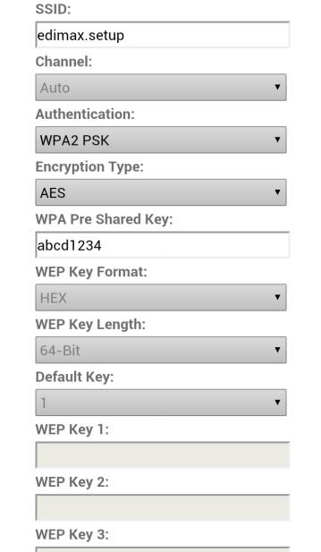
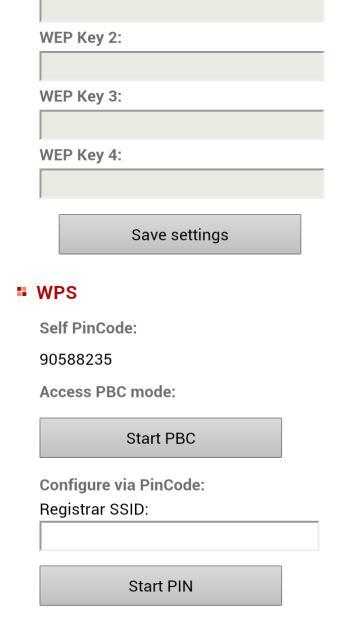
30 IV-1-2. Wireless The wireless page allows you to configure settings for your network camera s wireless connection. For Windows users, your wireless connection should have been set up already using EdiView Finder, though you can still use this page to revise the settings if you need. Mac users need to configure these settings manually since EdiView Finder on Mac will not set up your camera s wireless connection. A quick guide to set up your network camera s wireless connection using a smartphone or a computer is included below. Mac users setting their network camera s wireless connection for the first time please ensure your network camera is connected to your router/access point/switch via Ethernet cable. You can also use the wireless page for Wi-Fi Protected Setup (WPS): to either activate push-button WPS (the same effect as physically pushing the hardware WPS button built into the camera), or PIN code WPS (using a PIN code for verification between the two wireless devices for additional security.) 30


31 IV Smartphone 1. Select Basic from the menu on the left side and then select Wireless. 2. Configure the wireless settings A E shown in the table below: A C B 31
32 D E 32
33 A Wireless Connection Select Enable to enable the wireless connection. B Available Network (1) C Available Network (2) Click Refresh to display all available Wi-Fi networks. Select your Wi-Fi network from the list. This is the wireless network which your camera will connect to. D WPA Pre Shared Key Enter your Wi-Fi password. E Save Settings Click Save Settings to save your settings. 3. After the settings are saved, remove the Ethernet cable from your network camera. Your camera should now be connected to your Wi-Fi. 33
34 IV Computer 1. Configure the wireless settings A E shown in the table below: C A B D E A B C D Wireless Connection Select Enable to enable the wireless connection. Available Network Connected Click Refresh to display all available Wi-Fi networks. Select your Wi-Fi network from the list. This is the wireless network which your camera will connect to. WPA Pre Shared Key Enter your Wi-Fi password. E Save Settings Click Save Settings to save your settings. 2. After the settings are saved, remove the Ethernet cable from your network camera. Your camera should now be connected to your Wi-Fi. 34
35 IV WPS WPS (Wi-Fi Protected Setup) is a quick and easy way to set up wireless connections between compatible devices. Use the Start PBC or Start PIN button to activate WPS on your network camera. Your network camera s WPS PIN code is also listed next to Self PinCode. Self PinCode Access PBC Mode Configure via PinCode Your network camera s WPS PIN code is listed here. Click Start PBC to activate push-button WPS on your network camera. This has the same effect as physically pushing the built-in hardware WPS button. Enter the SSID you wish to connect to and click Start PIN to activate PIN code WPS. You will then need to enter the network camera s Self PinCode into your wireless router s web U.I. and activate your router s PIN code WPS. Please refer to your wireless router s instructions for help accessing its web-based interface and activating WPS. 35
36 IV-1-3. Dynamic DNS Dynamic DNS (DDNS) is a service which provides a hostname-to-ip service for dynamic IP users. If your Internet service provider didn t issue a fixed IP address, you can use a third-party dynamic DNS provider to map your current IP address to a fixed IP address. Several free or paid DDNS services are available online, please use the information provided by your DDNS provider to configure the settings on this page. Enable DDNS Provider Host Name User Name Password Select Enable to enable DDNS functionality, or select Disable to disable DDNS functionality. Select your dynamic DNS service provider from the dropdown menu. Enter the hostname you registered with the DDNS service provider. Enter the user name you registered with the DDNS service provider. Enter the password you registered with the DDNS service provider. 36
37 IV-1-4. RTSP Real Time Streaming Protocol (RTSP) enables the network camera to be used with a streaming media server. Enter the required RTSP settings. RTSP Port MJPEG RTSP Path RTP Port Range Verification Enter the RTSP port. Enter the MJPEG RTSP path. Enter the RTP port range. Select a verification type from the drop down menu. 37
38 IV-1-5. Date & Time You can set and adjust the network camera s system time and date on this page. Maintaining a correct system time is particularly important for recorded video organization/playback. Mode Set Time & Date Manually Synchronize to PC time NTP Server Time Zone Daylight Saving Select NTP or Manual Setting. NTP (Network Time Protocol) can set and maintain the time and date automatically via an NTP server on the local network, if available. For manual setting mode, enter the correct time and date in the following format: YYYY/MM/DD HH:MM:SS Click here to automatically enter the same time and date as your computer. For NTP mode, enter the NTP server s hostname or IP address. Select the correct time zone. Enable or disable daylight saving according your local time zone. 38
39 IV-1-6. Users In addition to the default administrator account, you can configure several different login accounts for the network camera, with two different levels of access operator and guest. Operator accounts can configure all functions of the network camera in the same way as the administrator account, while guest accounts can only view the camera s image. User List User Name Password Confirm password Existing users are listed here. Select a user here to modify the settings. Input user s name here. Input user s password here. Input user s password here again for confirmation. 39
40 Authority Add Modify Remove Anonymous Login Select the user s authority: Operators can view video and configure some settings, while guests can only view video. Add a new user. Save the changes to an existing, selected user. Remove selected user. Enable or disable anonymous login. Anonymous login allows anyone to login to the network camera and view images. This function is useful if you want to setup a remote video server. 40
41 IV-1-7. UPnP Universal plug-and-play (UPnP) is a set of networking protocols which enables network devices to communicate and automatically establish working configurations with each other. When enabled, Windows computers can automatically discover the network camera on the local area network. The network camera also supports IGD. Enable/Disable IGD Enable (UPnP Port Forward) IGD Configuration (External Port) External HTTP Port External RTSP Port Enable or disable UPnP. Enable or disable Internet Gateway Device (IGD). Select fully-automated or semi-automated IGD. Enter an external HTTP port. Enter an external RTSP port. 41
42 IV-1-8. Bonjour Bonjour is a feature of Mac computers which allows Safari web browser to discover devices and services on the local network and provide a quick shortcut for access. When enabled, Safari users on the local network can find a shortcut to the network camera under Safari s Bonjour menu. Select Enable or Disable. 42

43 IV-2. Video The Video menu consists of three categories for configuring the network camera s video settings. Select an item from the submenu and refer to the appropriate following chapter. IV-2-1. Video Settings The Video Settings page enables you to modify the network camera s resolution and frame rate settings. Format H264 Resolution Select which format to use for your video, H264 or MJPEG. Select a H264 video resolution from the dropdown menu. A higher resolution provides more detailed video but requires more bandwidth. Note: Motion detection cannot be used when 43
44 H264 Maximum Bit Rate MJPEG Resolution MJPEG Quality Maximum Frame rate Power frequency HD resolution is selected. Select a maximum bit rate for H264 videos from the dropdown menu. A higher bit rate provides more detailed video but requires more bandwidth. Select a MJPEG video resolution from the dropdown menu. A higher resolution provides more detailed video but requires more bandwidth. Select a quality level for MJPEG videos from the drop down menu. Higher quality requires more bandwidth. Select the maximum video frame rate. A higher frame rate provides smoother video, but also requires more bandwidth. Note: In dark environments, the network camera will automatically lower the frame rate to provide a better video quality, by using a longer exposure time. Adjust the power frequency to 50 Hz or 60 Hz frequency depending on your local region, in order to reduce flicker/improve playback in your videos. 44

45 IV-2-2. Image Appearance The Image Appearance page allows you to adjust various parameters relating to the network camera s image appearance using the sliders shown below. Brightness/ Contrast/ Saturation/ Sharpness/ Reset to default Save value Click and drag the blue lever to change the value according to your preference for each category. Click to reset all settings back to the default value of 50. Save changes. 45
46 IV-2-3. Night Vision Night-vision allows your network camera to capture images in dark environments by using infra-red LEDs. Auto-switch will detect light levels in your network camera s environment and automatically switch to night-vision in low light. Select Enable or Disable for night-vision auto-switch. 46
 events notification.")
47 IV-3. Events Select an item from the Events menu and refer to the appropriate following chapter. You can configure settings for motion detection, scheduling, SMTP and FTP. IV-3-1. Motion Detection The network camera features a motion detection function and various options for (motion detection) events notification. On this page you can enable or disable motion detection, event FTP upload and event s as well as set the interval time to detect. Motion detection regions can be configured according to your preference on the Detection Region page (see next chapter). 47
48 Motion Detection Interval Time To Detect Upload Event File to FTP Send Event File to Event File Format Video Recording Time Enable or disable the motion detection function of your network camera. After motion is detected, the network camera will not detect motion again for this length of time. For example, using an Interval Time To Detect of 20 seconds means that after motion is detected, the camera will not detect any further motion for 20 seconds. Then after 20 seconds, the camera will detect motion again. A snapshot image or short video of a detected event can be sent to a designated FTP server. Select Enable or Disable for this function. When enabled, you need to configure the FTP server information on the FTP page of the Events menu. A snapshot image or short video of a detected event can be sent to a designated recipient. Select Enable or Disable for this function. When enabled, you need to configure the SMTP server information on the SMTP page of the Events menu. Select a format for the event file which will be uploaded to FTP or sent to . JPEG is a snapshot image while H.264 is a video. When H.264 (video) is selected as the event file format, specify the length of time for the video recording here. 48

49 IV-3-2. Detection Region When using the network camera s motion detection function, you can specify the area in the video where the network camera should be sensitive to motion. Motion outside of the detection region will be ignored by the network camera. This is useful to avoid false alarms. Item Region 1 / Region 2 / Region 3 Description Check the box to enable up to three motion detection regions. A color-coded rectangle will appear on the video view for each enabled region. Adjust the size and position 49
50 Sensitivity Threshold Save of each box according to your preference by clicking and dragging inside the box (move) or on the edges (resize). Adjust the sensitivity level of motion detection for each region. A higher value will trigger the alarm for minor motion in the video and vice-versa. You can reduce the sensitivity level if you receive unnecessary event notifications. Adjust the motion detection threshold level for each region. A higher value will trigger the alarm for large objects in the video, a lower value will trigger the alarm for smaller objects. Save your settings. 50

51 IV-3-3. Schedule Settings The network camera can be scheduled to record automatically at/on specified times and days. Select Enable to enable this feature and then define at which times the network camera will record using the table below. For each day, click and drag across the timeline on the times which you want to record. A blue box indicates a scheduled recording. In the example below, recording is scheduled for 8am 6pm Monday to Saturday. 51
52 Delete Delete All Select All Store Delete the selected blue recording block on the timeline. Delete all blue recording blocks on the timeline. Select all blue recording blocks. Store the recording settings on the timeline. Note: Schedule settings must also be enabled for the schedule to come into effect. 52
53 IV-3-4. SMTP A snapshot image of a motion-detected event can be sent to a designated recipient. This function must be enabled in Motion Detection settings in the Events menu. Enter the required information about your sender and recipient accounts below. Service Provider SMTP Server SMTP Port Select Manual Settings to enter the information manually or select a common provider to enter some of the information automatically. Input the host name or IP address of the SMTP server for the sender. This information can be provided by your service provider. Input the SMTP port number for the sender. Most SMTP servers use port number 25, while some SMTP servers use encrypted connections with a port number of 465. This information can be provided by your 53
54 Recipient Address Sender Address SSL/TLS SMTP Authentication Account Password Send Test service provider. Enter the recipient s address here. Enter the sender s address here to avoid spam filter issues. Select SSL or TLS when your SMTP server requires encryption. Consult your mail server administrator when in doubt. Select Enable when your SMTP server requires authentication. This information can be provided by your service provider. Input the SMTP account name when your SMTP server requires authentication. This information can be provided by your service provider. Input the password used for SMTP server authentication. Click here to send a test with the current settings. 54
55 IV-3-5. FTP A snapshot image of a detected event can be sent to a designated FTP server. This function must be enabled in Motion Detection settings in the Events menu. Enter the required information about your FTP server below. FTP Server User Name Password Port Path Passive mode Enter the IP address or host name of the FTP server. Enter the user name required by the FTP server. Enter the password of the FTP server. Enter the port number of the FTP server. This value should be an integer between 1 and Please don t change this value unless advised by the FTP server s administrator. Enter a path (folder) to save files on the FTP server. If blank, files will be saved in the FTP server s default root folder. Enable or disable passive mode according to your FTP server. 55
 on/off according to your preference.")
56 IV-4. System The System menu consists of three categories, Basic, Advanced and Cloud Service. Select a category and follow the appropriate chapter for more information. IV-4-1. Basic The Basic menu enables you to set the camera s name and administrator password, as well as switch the LED(s) on/off according to your preference. Network Camera Name Administrator Password Confirm Password LED Indication Set the name of the network camera for reference/identification purposes. This is especially useful when managing multiple network cameras. Enter your desired administrator password here. This is the password used to log into the camera with the admin account. Confirm your desired administrator password here. Select On or Off to switch the network camera s LED(s) on or off. Switching off the LEDs can be a power saving measure or can be for security purposes, so that anybody who can see the network camera is unaware if the camera is active. 56
57 IV-4-2. Advanced The Advanced page allows you to upgrade the network camera s firmware, backup or restore the network camera s settings, and reset or restart the network camera. Please check the Edimax website for the latest firmware for your network camera. Do not switch off or disconnect the device during a firmware upgrade, as this could damage the device. Firmware Filename Upgrade Firmware Backup Settings Restore Settings Restart Click Browse to locate the firmware file on your computer. Click to upgrade the firmware to your selected file. Click Apply to save the current settings on your computer as config.bin file. Click Browse to find a previously saved config.bin file and then click Upload to replace your current settings. Click Restart Network Camera to restart the network camera. Please wait a couple of minutes for network camera to boot up after a restart. Restarting will not affect the camera s current configuration. 57
58 Reset to default Select Keep Network Settings or Default Settings and then click Reset to Default. When the camera resets, Keep Network Settings will reset all settings but keep the current network settings. The network camera s IP address will remain the same. Default Settings will reset all of the camera s settings, including network settings, back to the factory default status. 58
59 IV-4-3. Cloud Service Edimax Plug & View is a function to allow you to view your network camera remotely via a cloud server (see V. Myedimax.com). You can enable or disable this feature here. 59
60 IV-5. Status The Status menu provides important information about the status of the network camera. This information is useful for troubleshooting purposes or for network configuration. IV-5-1. System Information A summary of system-wide information about the network camera is displayed on this page, displayed under four categories: System, LAN, Wireless LAN and IGD (UPnP Port Forward). 60
61 61
 will only log critical information, while 4 (maximum) will log everything.")
62 IV-5-2. System Log A system log provides information about the network camera s usage and actions. The system log can also be sent to a remote server for archiving. Log Level Remote Log Remote Log Server Select a level of detail for the log from the dropdown list, from (minimum) will only log critical information, while 4 (maximum) will log everything. Enable or disable the network camera s remote log function, to send the log to a remote server for archiving. The network camera supports syslog log servers. Enter the IP address or host name of the log server you wish to use. 62
63 V. Myedimax.com You can use your network camera s Myedimax.com cloud ID to monitor your camera remotely using a web browser from any Internet connection. The network camera s green LED must display on to indicate a successful cloud connection, in order for this function to work. 1. Identify your network camera s cloud ID. The cloud ID is displayed in EdiView Finder (see III-1.) and on the product label on the back of the network camera (see I-5.). The cloud ID is a string of 12 characters consisting of numbers 0 9 and letters A F which is unique to your network camera. 2. Enter cloudid.myedimax.com into the URL bar of a web browser. For example, if your cloud ID is then enter myedimax.com into your web browser. Internet Explorer is recommended. 3. You may be prompted to allow a Java add-on to run. Please click the message where it says click here and then click Run Add-on. 63


64 If any other security warnings/prompts appear, please select Run or Allow or similar, depending on your browser. 4. Enter your camera s password (default password: 1234) and click OK to see a live stream from your network camera. 64

65 5. The network camera can be operated and configured using the icons in the toolbar located below the image. To configure the network camera, click window: to show the configuration menu 6. Use the slider controls to change the image brightness, saturation, sharpness, video quality and pan & tilt speed. Use the dropdown lists to change the video resolution and operating language, and click Apply when finished. 65


66 VI. 16 Channel Viewer for Windows The included 16 channel viewing software provides powerful access to your network camera s functions, along with the capability to view and manage up to 16 network camera simultaneously. VI-1. Installation 1. Insert the included CD into your CD-ROM drive and if the setup utility does not automatically open, please locate and open the Autorun.exe file in the Autorun folder. 2. Click 16 Channel Viewer to install the EdiView Finder software utility. 3. Click Next and follow the on-screen instructions to install the 16 channel viewer software. 66


67 4. Check the installation location and click Next to continue. 5. Click Next to continue. 6. A summary of your installation will be displayed. Please check everything is correct and click Install to begin the installation. 67


68 7. Please wait a moment for the installation to complete. 8. Click Finish and then double click the IPCam Surveillance Software icon on your desktop to open the software. 68
69 69

70 VI-2. Using the 16 Channel Viewer Your monitor s resolution must be 1024 x 768 for the 16 channel viewer to work properly. Please set your monitor s resolution to 1024 x 768. The main screen of the 16 channel viewer is described below: Video display area Language Display Layout Full screen & Scan PTZ Control & Home Message Display Box Close Program & Minimize Window Recording & System Configuration Playback & Snapshot 70
71 Video display area Language Display layout Full screen Scan PTZ control Home Recording System Configuration A live image of up to 16 connected cameras will be displayed in this area. Select a language from this dropdown menu to change the display language. Change camera image display layout (click a layout icon to change camera display layout). There are 8 kinds of display layouts available. Click this button to switch to full screen mode (only display all camera s image), press ESC key to quit full screen mode. Click this button and the network camera surveillance software will switch through the images of all connected camera automatically. Click this button once to activate the scan function (scan icon will become blue ), click again to stop scanning (scan icon will become white ). There are 8 directions in the Pan Tilt Zoom (PTZ) control ring. If the camera you connect to supports PTZ, you can use the PTZ control ring to change the direction that the camera faces. This function is only available for supported cameras. Click this button to return the camera to Home (default) position. This function is only available for supported cameras. Start video recording. Camera configuration and general options. Playback Snapshot Play back a recorded video file. A new window will open to locate recorded files. Take a snapshot of current the camera image. 71
72 Message display Close window (stop surveillance) Displays all system messages. Terminates network camera surveillance software. Minimize window Minimizes network camera surveillance software window. 72
 and a popup menu will appear: Please select Camera Configuration to configure/add cameras: Please select Unblock if you are prompted by Windows Security Alert that")
73 VI-3. Configuring the 16 Channel Viewer VI-3-1. Add Camera/Camera Configuration In order to use the 16 channel viewer software, you must configure/add each camera(s) that you wish to connect. Please click the wrench icon ( ) and a popup menu will appear: Please select Camera Configuration to configure/add cameras: Please select Unblock if you are prompted by Windows Security Alert that IPCamViewer has been blocked, or similar. 73

74 VI Camera In the Camera Configuration tab you can add and configure all the cameras you wish to connect to the viewer software. To connect a camera to the viewer software, you need to enter the required information in the Camera Configuration box. You can do this automatically by selecting your camera listed in the Camera Search box and clicking Select (recommended) or you can enter the information manually. All of the information required to add your network camera can be completed automatically by selecting your camera listed in the Camera Search box and clicking Select. Channel Camera Search Select Select the channel number you wish to use. All cameras found on your local network will be displayed in the Camera Search box. Select a camera listed in the Camera Search box, and click the Select button to automatically enter the required information to connect the selected camera in the Camera Configuration box. 74
75 Refresh Name Model IP Address Username Web Port Password Video Format** Reset OK Cancel Rescan the list of cameras on your local network. Enter the name of the camera here. The default name is the first 6 bytes of the camera s MAC address; you can change the name of the camera so you can remember the camera s location or purpose easily. Displays the model of the selected camera, this field cannot be changed. Input the IP address of the camera. Input the user name of the camera. Input the web port of the camera. By default it s 80. Input the password of the camera. Default password is You should change the entered password if you changed the password of the selected camera. Select the video encoding format of this camera (MJPEG or H.264). Clear all fields in the Camera Configuration section. Save settings. Discard all settings in this tab. **: Only available for cameras support this function. Click OK to save the settings and your network camera s image will be displayed in your selected channel on the 16 channel viewer s main screen: 75


76 VI Scheduled Recording In this tab, you can setup scheduled video recording, so you can record the video captured by all cameras you have according to a pre-defined schedule. 76
, then click OK to save settings.")
77 Channel One Time Schedules New (One Time Schedules) Select the channel number you wish to set. You can specify the one-time schedule for a selected camera; this schedule will be executed once only. Click this button and a new window will appear: Please specify the time duration of this onetime schedule (the date and time of From and To ), then click OK to save settings. Edit Delete New (Weekly Schedules) Please note you must set a schedule that will happen in the future, you cannot set a schedule in the past. You can modify a scheduled recording item. Select a schedule in One Time Schedules list, and click the Edit button to edit the start and end time of this schedule. Delete a selected schedule item. Click this button and a new window will appear: 77
, and the end time will be calculated automatically and displayed in the To field.")
78 You can define the recording schedule that will be executed at the specified time of certain weekday(s) in a week. Please check all weekdays that apply, and set the start time in the From field. You can set the duration of video recording in the Period field (format is HH:MM:SS), and the end time will be calculated automatically and displayed in the To field. You can also click the All Time Record button to define a recording schedule that will be executed every weekday, from 12:00:00AM to 11:59:59PM. Edit Delete OK Cancel Click OK to save changes. You can modify a scheduled recording item. Select a schedule in the One Time Schedules list, and click the Edit button to edit the start and end time of this schedule. Delete a selected schedule item. Save settings. Discard all settings in this tab. 78

79 VI Audio For cameras that support audio, you can use this tab to decide if you wish to hear the audio captured by the selected camera. Channel Mute Audio Record Video Only OK Cancel Select the channel number you wish to set. Check this box and the network camera surveillance software will not play the audio captured by this camera. Check this box and the network camera surveillance software will not record the audio captured by this camera. Save settings in this tab. Discard all settings in this tab. 79

80 VI Motion Recording The network camera features a motion detection function and various options for (motion detection) events notification. On this page you can enable or disable motion detection and set the camera to send an or trigger an alarm when motion is detected. Please not that when using the camera for security purposes, it is important to monitor the camera s stream even when using motion detection. Motion detection may not be 100% accurate. Channel Enable Disable Video Length Invoke alarm when motion is triggered Send mail when Select the channel number you wish to set. Enable motion record function. Disable motion record function. Select the time duration from the dropdown menu, in seconds, that the camera will record when a motion has been detected. Send an alarm when a motion has been detected by the camera. Send an to a pre-defined address when 80
81 motion is triggered OK Cancel a motion has been detected by the camera. Save settings in this tab. Discard all settings in this tab. 81
 and a popup menu will appear: When you select General Options, please refer to the appropriate")
82 VI-3-2. General Options Click the wrench icon( ) and a popup menu will appear: When you select General Options, please refer to the appropriate following chapter: VI General All general settings such as the file storage directory and recording spaces can be set here. 82
83 Data Directory Free Recording Space Max Video File Size Scan Time Cycle Recording OK Cancel Set the directory (folder) you wish to store the recorded video and captured image. You can click the Browse button to pick a directory on your hard disk. Displays remaining storage space. Defines the maximum file size of every video file. When the size of the file exceeds this value, the network camera surveillance software will open another file to record the video. Define the time period to pause between every camera switch when you activate the Scan function. You can decide the behavior when hard disk space is full: Disable: Do not overwrite recorded video files. Enable: Overwrite recorded video files. Save settings in this tab. Discard all settings in this tab. 83

84 VI Setting If you want to use the motion detection function and wish to receive an that contains the image captured by the camera, please set up your related parameters here first. Subject Recipient Address New Specify the subject of the sent . Lists all addresses you set. Click this button and you ll be prompted to input the address. Click OK to save changes. 84

85 Edit Select an address from the Recipient E- Mail Address box, and click Edit to edit the address. Delete Delete the selected address. Sender Specify the address that will appear as Address SMTP Server SMTP port SMTP Auth SMTP Account SMTP Password the sender. Specify the IP address or host name of the SMTP server you wish to use. Most ISPs will only allow their subscribers to use their SMTP server, if you don t know which SMTP server you should use, please refer to the settings in your software or ask your ISP / network administrator. Specify the port number of the SMTP server you wish to use here. By default (and the setting of most of SMTP servers) it s 25. Select Enable if your SMTP server requires authentication, select Disable if it s not required. If you don t know if your SMTP server requires authentication, please refer to the settings in your software or ask your ISP / network administrator. Input the SMTP account (username) of your SMTP server here. In most cases, it s the same as your POP3 username (the one you use to receive ). Please refer to the settings in your software or ask your ISP / network administrator if you re not sure about this. Input the SMTP password of your SMTP server here. In most cases, it s the same as 85
86 OK Cancel your POP3 password (the one you use to receive ). Please refer to the settings in your software or ask your ISP / network administrator if you re not sure about this. Save settings in this tab. Discard all settings in this tab. 86

87 VI Security You ll need to input the password every time you wish to use this network camera surveillance software: To set the password, please use the Security tab in the General Options menu: Here are the descriptions of all settings: 87
88 Enable Disable Password Confirm Password Requires password authentication when this software starts. Password authentication is not required when this software starts. Input the password you wish to use here. Input the password you wish to use here again. 88
89 VI About Software version is displayed in this tab. 89

90 VI-4. Changing the Display Layout This network camera surveillance software provides 8 display layouts: Every layout displays a different number of cameras in different arrangements, you can click the icon that represents a specific layout, and the video display area will change accordingly. Layout style 1: 1 Camera only Displays the video of 1 camera only. Layout style 2: 4 Cameras Displays the video of up to 4 cameras. Layout style 3: 6 Cameras Displays the video of up to 6 cameras. 90
91 Layout style 4: 8 Cameras Displays the video of up to 8 cameras. Layout style 5: 9 Cameras Displays the video of up to 9 cameras. Layout style 6: 10 Cameras Displays the video of up to 10 cameras. 91
92 Layout style 7: 13 Cameras Displays the video of up to 13 cameras. Layout style 8: 16 Cameras Displays the video of up to 16 cameras. 92
93 VI-5. Full Screen Mode If you want to use all available space on your monitor to display the surveillance image, you can click the Full Screen button to switch the display mode to full-screen mode. To exit full-screen mode, press the ESC key. 93
94 VI-6. Scan If you have more than one camera configured, and you wish to switch the display image between cameras, you can click the Scan button to switch between all configured cameras. Disconnected will be displayed in the image window when a configured camera is disconnected. Click the Scan button once to activate the scan function (the scan icon will become blue ), click again to stop scanning (the scan icon will become white ). 94
95 VI-7. Zoom In/Out For cameras that support the zoom-in / zoom-out function, you can use this function to see more objects within the camera s view, or enlarge the image size of a certain object to see it in detail. Please select a camera in the video display area by clicking on its image, then click the button to see more objects within the camera s view, or click to enlarge the image size of a certain object to see it in more detail (before zooming in, you may need to use the PTZ buttons - described in the next section - to find the object you wish to see in detail). 95
.")
96 VI-8. Pan & Tilt For cameras that support pan - tilt functions, you can change the direction that the camera points to, to see different places that fall within the camera s view. Please select a camera in the video display area by clicking on its image, and then click the directions you wish the camera to move to (total 8 directions available). Click the Home button ( ) to return to the camera s home (default) position. 96
97 VI-9. Snapshot You can take a snapshot of a selected camera and save it to a Snapshot subfolder in a pre-defined data directory. Click the snapshot button once to take a snapshot; you can take as many snapshots as you want until the hard disk is full. 97
98 VI-10. Recording You can start video recording a selected camera s image by clicking the Start Recording button: When recording starts, you ll see a message displayed in the message display box, such as 1/1 10:00:00, Camera 2 Start Manual, which means camera 2 started recording manually on 1/1 at 10:00:00. To stop recording, click the Start Recording button again, and you ll see a message displayed in the message display box such as 1/1 10:00:00, Camera 2 Stop Manual. 98
 and Motion Search (search all videos recorded by the motion detection function and")
99 VI-11. Video Playback You can playback all recorded video by clicking this button. A new window will appear: You have to search the video file before you can play it. There are two kinds of video search: Time Search (search all videos file that fall within a specific period of time) and Motion Search (search all videos recorded by the motion detection function and fall within a specific period of time). Please define the start and end date / time of the time period you wish to search, and then click the Search button (under Time Search or Motion Search ). All found videos will be displayed, select the video you wish to play and click the Play button to playback. 99


100 VII. EdiView App You can use the free EdiView smartphone app to monitor your camera remotely using a smartphone from any Internet connection. The network camera s green LED must display on to indicate a successful cloud connection, in order for this function to work. EdiView app screens may vary slightly according to version and future updates. 1. Search the Apple app store or Google Play for EdiView. Download and install the EdiView app. 100


101 2. Run the EdiView app. ios users select Add new camera and Android users select Yes to search for available cameras. 3. Select your network camera, enter the password when prompted (default password is 1234) and tap OK. ios: 101

102 Android: 4. Android users select the camera name and tap Done. ios users tap Live from the menu across the bottom of the screen. 102


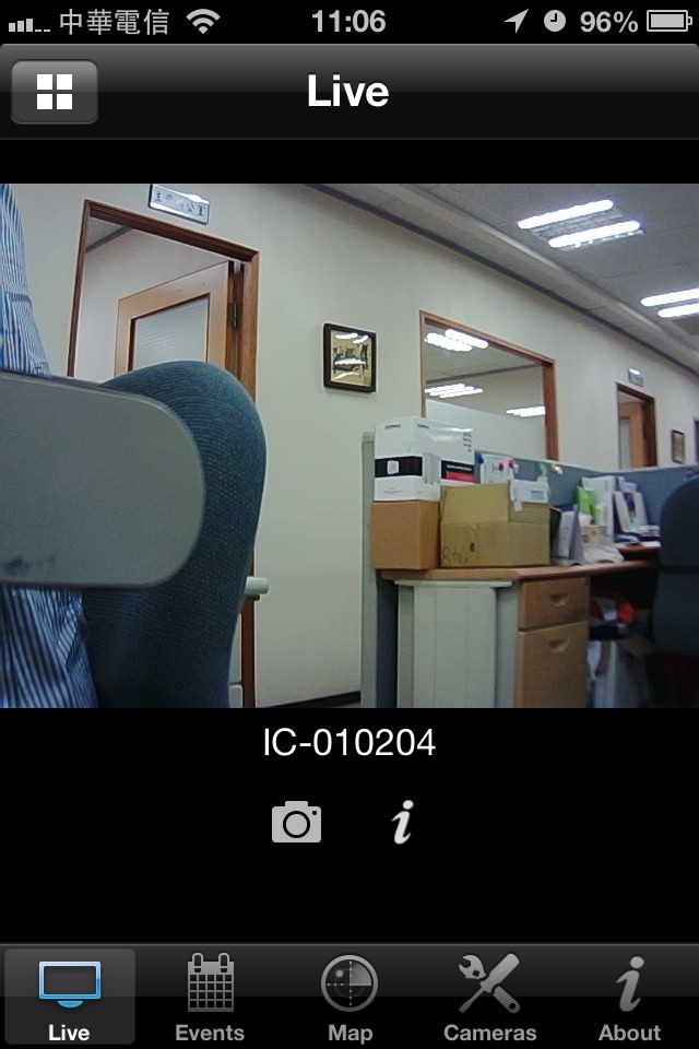
103 Android: ios: 103
IC-7001W User Manual
 IC-7001W User Manual 01-2017 / v1.1 Copyright @ Edimax Technology Co., Ltd. all rights reserved. No part of this publication may be reproduced, transmitted, transcribed, stored in a retrieval system, or
IC-3140W User Manual
 IC-3140W User Manual 01-2017 / v1.1 Copyright @ Edimax Technology Co., Ltd. all rights reserved. No part of this publication may be reproduced, transmitted, transcribed, stored in a retrieval system, or
IC-7112W User Manual
 IC-7112W User Manual 09-2015 / v1.0 Copyright @ Edimax Technology Co., Ltd. all rights reserved. No part of this publication may be reproduced, transmitted, transcribed, stored in a retrieval system, or
IC-5170SC User Manual
 IC-5170SC User Manual 09-2016 / v1.0 Copyright @ Edimax Technology Co., Ltd. all rights reserved. No part of this publication may be reproduced, transmitted, transcribed, stored in a retrieval system,
IC-5160GC User Manual
 IC-5160GC User Manual 06-2016 / v1.0 Copyright @ Edimax Technology Co., Ltd. all rights reserved. No part of this publication may be reproduced, transmitted, transcribed, stored in a retrieval system,
3G-6408n User Manual
 3G-6408n User Manual 05-2012 / v1.0 COPYRIGHT Copyright Edimax Technology Co., Ltd. all rights reserved. No part of this publication may be reproduced, transmitted, transcribed, stored in a retrieval system,
WIRELESS 11N HD IP CAMERA
 WIRELESS 11N HD IP CAMERA User Manual DN-16026 -CONTENTS- Chapter I Introduction... 5 1.1 Highlights of your new Network IP Camera... 5 1.2 Safety Instructions... 6 1.3 Packaging Contents... 7 1.4 Install
TENVIS Technology Co., Ltd. User Manual. For H.264 Cameras. Version 1.0.0
 TENVIS Technology Co., Ltd User Manual For H.264 Cameras Version 1.0.0 Catalogue Basic Operation... 3 Hardware Installation... 3 Search Camera... 3 For Internet Explorer... 6 Playback Record Files... 9
DG-HR1160M Portable Power Bank 3G Router User Manual
 DG-HR1160M Portable Power Bank 3G Router User Manual V1.0 2013-11-14 As our products undergo continuous development the specifications are subject to change without prior notice COPYRIGHT Copyright 2013
Wireless PTZ Cloud Camera TV-IP851WC (v1.0r)
") (v1.0r) TRENDnet s Wireless PTZ Cloud Camera, model, takes the work out of viewing video over the internet. Previously to view video remotely, users needed to perform many complicated and time consuming
(v1.0r) TRENDnet s Wireless PTZ Cloud Camera, model, takes the work out of viewing video over the internet. Previously to view video remotely, users needed to perform many complicated and time consuming
Configuring and Managing the IP Camera
 CHAPTER 3 The Cisco Video Surveillance IP Camera provides configuration windows that you use to configure and manage the IP camera. This chapter explains how to access the configuration windows, describes
GRAND IP VIDEO SERVER PRO. User s Manual INDEX
 INDEX GRAND IP VIDEO SERVER PRO Video & Audio Transmission/ iphone Web Browser Support User s Manual ISSUE:Mar 16, 2010 1. Package Contents.... 1 2. Introduction.... 1 3. System Requirements...... 1 4.
Edimax Pro NMS Quick Installation Guide
 Edimax Pro NMS Quick Installation Guide 10-2014 / v1.0 Product Information Edimax Pro Network Management Suite (NMS) supports the central management of a group of access points, otherwise known as an AP
Wireless Day / Night Cloud Camera TV-IP751WIC (v1.0r)
") (v1.0r) TRENDnet s Wireless Day / Night Cloud Camera, model, takes the work out of viewing video over the internet. Previously to view video remotely, users needed to perform many complicated and time
(v1.0r) TRENDnet s Wireless Day / Night Cloud Camera, model, takes the work out of viewing video over the internet. Previously to view video remotely, users needed to perform many complicated and time
COPYRIGHT. Linux Open Source Code Certain Edimax products include software codes developed by third parties, which are
 COPYRIGHT Copyright Edimax Technology Co., Ltd. all rights reserved. No part of this publication may be reproduced, transmitted, transcribed, stored in a retrieval system, or translated into any language
Wireless Day / Night PTZ Cloud Camera TV-IP851WIC (v1.0r)
") (v1.0r) TRENDnet s Wireless N Day / Night PTZ Cloud Camera, model, takes the work out of viewing video over the internet. Previously to view video remotely, users needed to perform many complicated and
(v1.0r) TRENDnet s Wireless N Day / Night PTZ Cloud Camera, model, takes the work out of viewing video over the internet. Previously to view video remotely, users needed to perform many complicated and
SAMSUNG ALL-IN-ONE SECURITY SYSTEM
 Quick Start Guide KIT MODEL SDH-B74041/SDH-B74081 DVR MODEL SDR-B74301 SAMSUNG ALL-IN-ONE SECURITY SYSTEM Thank you for purchasing the Samsung DVR Security System. Follow the simple steps in this guide
XIPLED Software User s Manual. For Firmware release V3.5.0.*
 XIPLED1080-36 Software User s Manual For Firmware release V3.5.0.* Product name: XIPLED1080-36 Release Date: 2014/10/02 Manual Revision: V02 Feature XIPLED1080-36 Live View All Series Camera/Video/Audio
BR-6428HPn User Manual
 BR-6428HPn User Manual 05-2012 / v1.0 COPYRIGHT Copyright Edimax Technology Co., Ltd. all rights reserved. No part of this publication may be reproduced, transmitted, transcribed, stored in a retrieval
NS15WG 1080P Web App User Manual
 NS15WG 1080P Web App User Manual Table of Contents 1. Getting Started... 4 Download the Web App...4 2. Web App Top Menu... 5 Live Video...6 Video Playback...6 Settings...6 3. Device Configuration... 6
User Manual. For H.264 Cameras. Version 2.0.0
 User Manual For H.264 Cameras Version 2.0.0 Catalogue Basic Operation... 3 Camera Settings... 3 System... 3 Device Name... 4 Time... 4 User... 4 Network... 5 IP... 5 Port... 5 WiFi... 6 UPnP... 6 DDNS...
Neposmart NS14WG Indoor and NS14BG Outdoor Camera Web App User Manual
 Neposmart NS14WG Indoor and NS14BG Outdoor Camera Web App User Manual TM Contents Using the Desktop Web Interface... 3 Viewing Video Using VLC Media Player... 6 Web on Internet Explorer and Neposmart Control
ErP Announcement. - General purposes: Record/monitor environment footage and sound and store them onto a hard disk as a record.
 1 ErP Announcement Product: Internet Camera (IP Camera) Purpose: 24 hour surveillance and transfer of footage for safety and health reasons as intented use. Detailed description: - Health purposes: Users
NVR Equipment WEB Operation Guide ISSUE V1.1 DATE
 NVR Equipment WEB Operation Guide ISSUE V1.1 DATE 2018-05-15 About This Document About This Document Purpose This document describes how to use the web management system for NVR and the cameras managed
1. Introduction Overview Product Information... 3
 1. Introduction... 3 1.1 Overview... 3 1.2 Product Information... 3 2. Device Connection... 3 2.1 Connection Diagram... 3 2.2 Wi-Fi Setting... 4 2.2.1 Set up WiFi by Mobile Phone... 4 2.2.2 WPS/QSS One
Wire/ Wireless 11b/g IP Camera User Manual
 IC-3010 / IC-3010Wg Wire/ Wireless 11b/g IP Camera User Manual Version 1.0 April 2008 C A T A L O G Chapter I: Familiar with your Internet IP Camera...3 1.1 Package Contents...3 1.2 Basic Introduction...4
Network Camera Firmware Upgrade Quick Guide
 Network Camera Firmware Upgrade Quick Guide 09-2018 / v1.0 1 CONTENTS I Introduction... 3 II How to Upgrade Firmware for Network Camera... 4 III Download App... 11 2 I Introduction To strengthen the security
ALL-IN-ONE SECURITY SYSTEM
 DO NOT OPEN CAUTION : TO REDUCE THE RISK OF ELECTRICAL SHOCK DO NOT OPEN COVERS. NO USER SERVICEABLE PARTS INSIDE. REFER SERVICING TO QUALIFIED SERVICE PERSONNEL. WARNING : TO PREVENT FIRE OR SHOCK HAZARD.
HD Pan Tilt IP Camera
 IP Camera User Guide Version 1.0.0.1 HD Pan Tilt IP Camera NIP-09L2J NIP-16L2J NIP-22L2J NIP-21L2J Page 1 Content 1. Hardware installation... 4 1.1 Hardware connection... 4 1.2 Network connection...5 1.3
HD Pan Tilt IP Camera
 IP Camera User Guide Version 1.0.0.1 HD Pan Tilt IP Camera Page 1 Content 1. Hardware installation... 4 1.1 Hardware connection... 4 1.2 Network connection...5 1.3 WPS setting...5 2. ipad, iphone App introduction...5
GV-IP Decoder Box Plus User s Manual
 GV-IP Decoder Box Plus User s Manual Before attempting to connect or operate this product, please read these instructions carefully and save this manual for future use. DBPV10-UM-A 2015 GeoVision, Inc.
Notice according to GNU/GPL-Version 2
 Copyright by Edimax Technology Co, LTD. all rights reserved. No part of this publication may be reproduced, transmitted, transcribed, stored in a retrieval system, or translated into any language or computer
Lorex Client 7.0 & Lorex Message Master
 Lorex Client 7.0 & Lorex Message Master Software Manual English Version 1.0 MODELS: L19WD Series www.lorexcctv.com Includes L19WD800 & L19WD1600 Copyright 2008 Lorex Technology Inc. Table of Contents Table
F312A IP Camera. Firmware User Manual
 0 F312A User Manual F312A IP Camera F312A User Manual Firmware User Manual - Contents - CHAPTER 1. MINIMUM SYSTEM REQUIREMENT...2 CHAPTER 2. USING IP CAMERA VIA WEB BROWSER...3 2.1WINDOWS WEB BROWSER...3
HooToo IP Camera User Manual(part two)
") HooToo Inc. HooToo IP Camera User Manual(part two) For Model: HT-IP210P Published by SunvalleyTek Group 2014/9/14 Content 1. IPCamClient (windows software)...3 Set up...3 CAM... 13 Local Setting... 13
HooToo Inc. HooToo IP Camera User Manual(part two) For Model: HT-IP210P Published by SunvalleyTek Group 2014/9/14 Content 1. IPCamClient (windows software)...3 Set up...3 CAM... 13 Local Setting... 13
F510E BOX IP Camera. Firmware User Manual
 0 F510E User Manual F510E BOX IP Camera F510E User Manual Firmware User Manual - Contents - CHAPTER 1. MINIMUM SYSTEM REQUIREMENT... 2 CHAPTER 2. USING IP CAMERA VIA WEB BROWSER... 3 CHAPTER 3. USING IP
VMS-A1 Client Software. User Manual
 VMS-A1 Client Software User Manual Contents Contents... 2 Chapter1. Overview... 4 1.1 Description... 4 1.2 Features & Functions... 4 Chapter2. Update Info... 6 Chapter3. Starting VMS-A1... 7 3.1 Installing
Multi-NVR Manager. Quick Start Configuration Usage
 Multi-NVR Manager Quick Start Configuration Usage 2014. All rights are reserved. No portion of this document may be reproduced without permission. All trademarks and brand names mentioned in this publication
Configuring and Managing the IP Camera
 CHAPTER 3 The Cisco Video Surveillance IP Camera provides configuration windows that you use to configure and manage the IP camera. This chapter explains how to access the configuration windows, describes
Central Management Software for NVR-915 / NVR-1615 CV5-M256
 Central Management Software for NVR-915 / NVR-1615 Table of Contents Chapter 1. Main Console... 4 1.1 Tool Bar... 4 1.2 NVR List... 5 1.3 Division List... 7 1.4 Group List... 9 1.5 PTZ Panel...11 1.6 Operation
SLS-ENVR2016 Network Video Recorder V2.2.2 Quick Setup Guide
 SLS-ENVR2016 Network Video Recorder V2.2.2 Quick Setup Guide The SLS-ENVR2016 series NVR is an intelligent and compact appliance that provides a network interface to monitor, record and playback video
M511E Pan/Tilt Day/Night IP Camera Firmware User Manual
 0 M511E User Manual M511E User Manual M511E Pan/Tilt Day/Night IP Camera Firmware User Manual - Contents - CHAPTER 1. MINIMUM SYSTEM REQUIREMENT... 2 CHAPTER 2. USING IP CAMERA VIA WEB BROWSER... 3 2.1WINDOWS
IP Camera. User Manual
 501583 IP Camera User Manual Version: 1.2 Released Date: June., 2005 Contents 1. Introduction... 3 2. Package Content... 3 3. System Requirement... 3 4. Hardware Installation... 4 4.1. LED and Focusing...4
Cisco WVC210 Wireless-G Pan Tilt Zoom (PTZ) Internet Video Camera: 2-Way Audio Cisco Small Business Video Surveillance Cameras
 Internet Video Camera: 2-Way Audio Cisco Small Business Video Surveillance Cameras") Cisco WVC210 Wireless-G Pan Tilt Zoom (PTZ) Internet Video Camera: 2-Way Audio Cisco Small Business Video Surveillance Cameras High-Quality, Flexible, Remote-Controlled Wireless Video Solution for Your
Cisco WVC210 Wireless-G Pan Tilt Zoom (PTZ) Internet Video Camera: 2-Way Audio Cisco Small Business Video Surveillance Cameras High-Quality, Flexible, Remote-Controlled Wireless Video Solution for Your
LeFun IP Camera Quick Install Guide
 LeFun IP Camera Quick Install Guide Website: www.lefunsmart.com E-mail: support@lefunsmart.com Catalog 1. Introduction... 2 1.1. Thank you for Choosing LeFun IP Camera... 2 1.2. Introducing LeFun IP Camera...2
TABLE OF CONTENTS 1 INTRODUCTION Overview of Cameramanager go!... 4
 User manual TABLE OF CONTENTS 1 INTRODUCTION... 4 1.1 Overview of Cameramanager go!... 4 2 GETTING STARTED... 5 2.1 Connect and activate Cameramanager go!... 5 2.2 Start the online Java application...
Megapixel PoE Day / Night PTZ Internet Camera TV-IP672PI (V1.0R)
") Megapixel PoE Day / Night PTZ Internet Camera (V1.0R) The Megapixel PoE Day / Night PTZ Internet Camera, model, provides day and night security over a large area. Pan the camera side-to-side a remarkable
Megapixel PoE Day / Night PTZ Internet Camera (V1.0R) The Megapixel PoE Day / Night PTZ Internet Camera, model, provides day and night security over a large area. Pan the camera side-to-side a remarkable
Quick Install Guide. Model: PLC-223W, PLC-233W
 Quick Install Guide Model: PLC-223W, PLC-233W This installation guide provides basic instructions for installing the PLC-213W/ PLC-223W/PLC-233W indoor wireless IP camera on your network. By following
LOREX CLIENT Remote Agent Software
 LOREX CLIENT Remote Agent Software Instruction Manual English Version 1.0 MODEL: L500 Series www.lorexcctv.com Copyright 2006 LOREX Technology Inc. Table of Contents Table of Contents About the Lorex Client...
Wireless N Day / Night Internet Camera TV-IP551WI (v1.0r)
") The, model TV- IP551WI, transmits real-time video over the Internet. Record crisp video in complete darkness for distances of up to 7.5 meters. Wireless n technology provides unsurpassed wireless coverage
The, model TV- IP551WI, transmits real-time video over the Internet. Record crisp video in complete darkness for distances of up to 7.5 meters. Wireless n technology provides unsurpassed wireless coverage
Cisco WVC210 Wireless-G Pan Tilt Zoom (PTZ) Internet Video Camera: 2-Way Audio Cisco Small Business Video Surveillance Cameras
 Internet Video Camera: 2-Way Audio Cisco Small Business Video Surveillance Cameras") Cisco WVC210 Wireless-G Pan Tilt Zoom (PTZ) Internet Video Camera: 2-Way Audio Cisco Small Business Video Surveillance Cameras High-Quality, Flexible, Remote-Controlled Wireless Video Solution for Your
Cisco WVC210 Wireless-G Pan Tilt Zoom (PTZ) Internet Video Camera: 2-Way Audio Cisco Small Business Video Surveillance Cameras High-Quality, Flexible, Remote-Controlled Wireless Video Solution for Your
QRT-502. IE Operation Manual
 QRT-502 IE Operation Manual Contents 1. Home.. 2 2. Replay.... 5 3. Media.... 6 3-1. Video.... 6 3-2. Audio.... 7 3-3. Image.... 8 3-4. OSD.... 9 3-5. PTZ (Not supported in QRT-501) 4. Parameters.... 10
NVR-0316 User s Manual 1 NVR User s Manual. Version 1.0.0
 NVR-0316 User s Manual 1 NVR-0316 User s Manual Version 1.0.0 2 NVR-0316 User s Manual Table of Contents Hardware... 4 Overview... 4 LED & Buttons Definitions... 4 Connect to the NVR... 5 Use NVR Search
Wireless Network Video Recorder
 LD2R/LD2R500 Wireless Network Video Recorder User Guide Version 1.0 PREFACE Thank you for purchasing the Wireless Network Video Recorder, an IP based device that installed on your network, which can be
EW-7478AC User Manual
 EW-7478AC User Manual 03-2016 / v1.0 CONTENTS I. Product Information...1 I-1. Package Contents... 1 I-2. System Requirements... 1 I-3. LED Status... 2 I-4. Switch... 3 I-5. WPS Setup... 5 I-6. WPS Button
Setup and Advanced User Guide
 N E T W O R K I N G A N D S U R V E I L L A N C E P R O D U C T S Setup and Advanced User Guide Astak, Inc. 1911 Hartog Drive San Jose, CA 95131 Tel : (408) 453-1188 Fax : (408) 453-1388 Table of Contents
IP Mini PTZ CAMERA USER GUIDE
 IP Mini PTZ CAMERA USER GUIDE TYPE A: To switch the mount style, remove the two screws on the pan bottom and rotate 180 degree to remount. This Mini PTZ cylinder camera can support both wall mount and
Product and company names appearing in this document are trademarks of each respective company or organization.
 . CMS_beta LEGAL INFORMATION Reproduction, transfer, distribution or storage of part or all of the contents in this document in any form without the prior written permission of the company is prohibited.
Iomega EZ Media & Backup Center Users Guide D
 Iomega EZ Media & Backup Center Users Guide D31593401 Table of Contents Setting up Your Device... 1 Setup Overview... 1 Set up My Iomega StorCenter If It's Not Discovered... 2 Discovering with Iomega
EW-7438RPn Mini User Manual
 EW-7438RPn Mini User Manual 04-2015 / v1.1 CONTENTS I. Product Information... 1 I-1. Package Contents... 1 I-2. System Requirements... 1 I-3. LED Status... 1 I-4. Hardware Overview... 3 I-5. Safety Information...
PRODUCT OVERVIEW... 1
 Table of Contents PRODUCT OVERVIEW... 1 PACKAGE CONTENTS... 1 SYSTEM REQUIREMENTS... 1 INTRODUCTION... 1 FEATURES... 2 HARDWARE OVERVIEW (IPC1000W)... 3 Front View... 3 HARDWARE OVERVIEW (IPC1000W)...
Internet Camera. User Manual
 Internet Camera User Manual Version: 1.1 Released Date: Dec., 2004 Contents 1. Introduction... 3 2. Package Content... 3 3. System Requirement... 3 4. Hardware Installation... 4 4.1. LED and Focusing...4
Wireless IP Bird Box Camera
 Wireless IP Bird Box Camera Model: 4901-18 Operation and Installation Manual 1 WELCOME... 3 PRODUCT OVERVIEW... 4 HARDWARE INSTALLATION... 4 Attach the External Power Adapter... 4 SMARTPHONE OR TABLET
IP Camera user manual
 IP Camera user manual Product name:high definition IP Camera Document version:4.2 Editions suit for 1080P IP Camera Precautions Search and Login...1 Device searching...2 Install plugin...3 A. Real-time
CHAPTER 1. Welcome to Grand IP Camera III
 CHAPTER 1 Welcome to Grand IP Camera III 3. Remote view through the IE browser, simply type in the IP address. 4. 6 infrared LEDs provide imaging in the dark. 5. Many Valuable Internet services: Email,
User Manual of Network Camera. Network Camera. User Manual UD.6L0201D1919A01
 User Manual of Network Camera Network Camera User Manual UD.6L0201D1919A01 1 Table of Contents Chapter 1 System Requirement... 10 Chapter 2 Network Connection... 11 2.1 Setting the Network Camera over
Megapixel PoE Day / Night Dome Internet Camera TV-IP262PI (v1.0r)
") Megapixel PoE Day / Night Dome Internet Camera TRENDnet s Megapixel PoE Dome Day / Night Internet Camera, model, provides powerful megapixel night vision in complete darkness for up to 12 meters (40 feet).
Megapixel PoE Day / Night Dome Internet Camera TRENDnet s Megapixel PoE Dome Day / Night Internet Camera, model, provides powerful megapixel night vision in complete darkness for up to 12 meters (40 feet).
ALIBI Witness 2.0 v3 Smartphone App for Apple ios Mobile Devices User Guide
 ALIBI Witness 2.0 v3 Smartphone App for Apple ios Mobile Devices User Guide ALIBI Witness 2.0 v3 is a free application (app) for Apple ios (requires ios 7.0 or later). This app is compatible with iphone,
M511W Wireless Pan/Tilt IP Camera Firmware User Manual
 0 M511W User Manual M511W User Manual M511W Wireless Pan/Tilt IP Camera Firmware User Manual - Contents - CHAPTER 1. MINIMUM SYSTEM REQUIREMENT... 2 CHAPTER 2. USING IP CAMERA VIA WEB BROWSER... 3 2.1WINDOWS
Linux Open Source Code Certain Edimax products include software code developed by third parties, software code
 English COPYRIGHT Copyright by Edimax Technology Co, LTD. all rights reserved. No part of this publication may be reproduced, transmitted, transcribed, stored in a retrieval system, or translated into
H Series MiNi High Speed Dome. IP Camera. May 2011 V User Manual
 H Series MiNi High Speed Dome IP Camera May 2011 V1.1.0.1.2 User Manual Index 1 INTRODUCTION... 3 2 FUNCTION AND FEATURES... 3 3 APPEARANCE AND INTERFACE... 4 4 NETWORK CONNECTING... 7 2 1 Introduction
BlackVue C App Manual
 BlackVue C App Manual BlackVue C App Manual Contents Connecting to BLACKVUE CLOUD... 3 (A) Create an account... 3 (B) Register your dashcam with your account... 3 (C) Connect your BlackVue dashcam to a
HD IP CAMERA USER GUIDE
 HD IP CAMERA USER GUIDE Support US: support@onwote.com EU: eusupport@onwote.com AU: ausupport@onwote.com Feature Lists 7x24 hours online live HD video preview Remote access via multiple web browsers(ie/firefox,
USER MANUAL. Mac Version
 USER MANUAL Mac Version Contents 1 Software Introduction... 1 1.1 Summary... 1 1.2 Install and Uninstall... 1 1.2.1 Install the Software... 1 2 Login Software... 3 2.1 Login... 3 2.2 Control Panel Instruction...
EN-9260TX-E User Manual
 EN-9260TX-E User Manual 09-2012 / v2.0 1 COPYRIGHT Copyright Edimax Technology Co., Ltd. all rights reserved. No part of this publication may be reproduced, transmitted, transcribed, stored in a retrieval
HIP2P Network Video Camera Client Terminal User Manual
 HIP2P Network Video Camera Client Terminal User Manual Document version:5.1 Page 1 of 34 } Preface Thank you for using our company's products. The network video camera client terminal is used to implement
SOHO NETWORK IP CAMERA USER MANUAL
 SOHO NETWORK IP CAMERA USER MANUAL MODEL 503365 INT-503365-UM-0407-02 Contents section page 1. Introduction... 1 2. Package Contents... 2 3. System Requirements... 2 4. Hardware Installation... 3 4.1 LED
Installation Instructions Fig. 3 Side View. No. Label Operation
 One-Camera IP Video Server In G Out G D+ D- Installation Instructions 1507280 Part Number: CM2002 - One-Camera IP Video Server CM2002 IP Video Server Features In G Out G D+ D- DO G DI G Out In Video In
QRT-501 IE Operation Manual
 QRT-501 IE Operation Manual Contents Log In...5 Main Screen...6 Task Bar...7 Right Panel Control...8 Configure the Camera Settings...9 Device Basic Information... 10 View the Device Information...10 Change
IP Camera User Manual
 the world through my eyes R IP Camera User Manual EN App Store Google Play Version:TWS20180723 1Product description 1.1Product Feature 1.2Package Contents 1.3IP Camera Overview 1.4Operating System Requirement
Smart Home System Kit
 Smart Home System Kit IP SECURITY ALARM SERIES More information, please visit the online CD information on the website http//netcam360.com 0 P a g e BRIEF INSTRUCTION 1. Start Infrared box camera a. Install
BlackHawk for MAC Software User Guide
 BlackHawk for MAC Software User Guide Products: BLK-DH2 Series and BLK-HD Series DVRs Please read this manual before using your software, and always follow the instructions for safety and proper use. Save
Zavio P5111/ P5116/ P5210 Quick Installation Guide
 86085M2000010 Zavio P5111/ P5116/ P5210 Quick Installation Guide Installation Steps Please follow the installation steps below to set up your P5111 / P5116/ P5210 Day/Night Pan/Tilt IP Camera. Check the
LevelOne FCS Mbps IP Network Camera User s Manual
 LevelOne FCS-1020 100Mbps IP Network Camera User s Manual Contents 1. Introduction...3 2. Package Content...3 3. System Requirement...3 4. Hardware Installation...4 4.1. LED and Focusing...4 4.2. Camera
wificam User's Guide Report Version: Date: November
 User's Guide Report Version: 2.0.3 Date: November 9 2004 3JTech Co., Ltd. 342 Fu-Hsing N. Rd., 2F Taipei, Taiwan Tel: +886-2-2500 6919 e-mail: info@3jtech.com.tw 1 Revision History Version Date Changes
CV-7428nS User Manual
 CV-7428nS User Manual 09-2012 / v1.0 1 COPYRIGHT Copyright Edimax Technology Co., Ltd. all rights reserved. No part of this publication may be reproduced, transmitted, transcribed, stored in a retrieval
The Intelligent Surveillance Solution. NVRmini 2. User Manual. Ver
 The Intelligent Surveillance Solution NVRmini 2 User Manual Ver. 2.2.1.150211.00 Table of Contents 1. Installation... 8 1.1 Installation Process... 8 1.2 LED Status Definitions... 16 2. Settings... 17
QUICK START GUIDE QT IP CAMERA & NVR BUNDLE ENGLISH
 QUICK START GUIDE QT IP CAMERA & NVR BUNDLE ENGLISH Table of Contents Welcome What s Included...3 Understanding your NVR...4 Get Connected Registration...5 Connect Your Cameras...5 Connect NVR to Display...6
NVMS User Manual. Version 2.1.0
 NVMS-1000 User Manual Version 2.1.0 Contents 1 Software Introduction... 1 1.1 Summary... 1 1.2 Operation Environment... 1 1.3 Install and Uninstall... 2 1.3.1 Install the Software... 2 1.3.2 Uninstall
HELP...48 Installing the DCS-2121 Behind a Router ) Identify Your Camera on the Network ) Assign a Local IP Address and Port for Your
 Identify Your Camera on the Network ) Assign a Local IP Address and Port for Your") Table of Contents Package Contents...1 Minimum System Requirements...2 Introduction...3 Features and Benefits...4 Hardware Overview...5 Hardware Installation...7 Attach the Antenna...7 Connect the camera
Table of Contents Package Contents...1 Minimum System Requirements...2 Introduction...3 Features and Benefits...4 Hardware Overview...5 Hardware Installation...7 Attach the Antenna...7 Connect the camera
IPCAMHD61 User Manual
 IPCAMHD61 User Manual TABLE OF CONTENTS: PRODUCT STRUCTURE DIAGRAM SETUP AN ACCOUNT USERNAME ADD CAMERA TO APP CONNECT TO YOUR NETWORK WEB ACCESS PASSWORDS MOBILE APP LAYOUT CAMERA VIEW PAGE CAMERA RECORDINGS
Configuring and Managing the IP Camera
 CHAPTER 3 The Cisco Video Surveillance IP Camera provides configuration windows that you use to configure and manage the IP camera. This chapter explains how to access the configuration windows, describes
Wanscam. HW series IP Camera PC Web User Manual
 Wanscam HW series IP Camera PC Web User Manual Packing list: IP camera Mounting bracket Antenna Adaptor CD Lan cable Installation guide Screws Note: Some models don t have a separate antenna. Installation
RM Series IP Cameras. Configuration manual. WiFi IP Cameras CONFIGURATION MANUAL RM SERIES - IP CAMERAS WIFI. How to configure camera options
 Page: 1 RM Series IP Cameras WiFi IP Cameras Configuration manual How to configure camera options Page: 2 Contents of this handbook The range of RM series cameras is a range of IP cameras for network connection
IP Night/Day Camera USER MANUAL
 IP Night/Day Camera USER MANUAL Table Of Contents 1. INITIAL INSTALLATION... 4 2. IP CAMERA FINDER... 8 3. IP CAMERA MANAGER... 11 3.4 Camera Software Navigation Buttons... 12 3.5 Adding Another Camera...
7. Server Configuration Introduction Search for All Available MFP Server Status of MFP Server
 Copyright by Edimax Technology Co, LTD. all rights reserved. No part of this publication may be reproduced, transmitted, transcribed, stored in a retrieval system, or translated into any language or computer
HD IP CAMERA USER GUIDE
 HD IP CAMERA USER GUIDE Feature Lists 24 x 7 online live HD video preview Remote access via multiple web browsers(ie/firefox, etc.) Easy P2P monitoring via smart phone APP(Android/IOS) ONVIF compatible,easy
300 Series Cube Wireless HD Surveillance Camera with Microphone. Installation Manual. Important! Ensure your NVR has the latest firmware!
 300 Series Cube Wireless HD Surveillance Camera with Microphone Installation Manual Important! Ensure your NVR has the latest firmware! Read this page before you go to the job site! 2 For maximum control
User Manual of P2P IP Cameras
 Updated on 20 August, 2013 User Manual of P2P IP Cameras This user manual applies to all the P2P IP Cameras as follows IPA Series: Home Pan-tilt IP Cameras IPB Series: Outdoor Waterproof IP Cameras IPC
Pro71600N3 NVR User Manual
 Pro71600N3 NVR User Manual User Information Admin User Name: Admin Password: IP Address: System Name: Table Of Contents 1. Menu Operation...4 1.1 Main Menu...4 2. Start & Shutdown System...5 2.1 Start