AX34 Online Manual AX34
|
|
|
- Myles Fisher
- 6 years ago
- Views:
Transcription
1 AX34
2 AX What s in this manual...2 Before You Start...9 Quick Installation Procedure Motherboard Map Block Diagram Hardware...13 JP14 Clear CMOS CPU Socket CPU and Housing Fan Connector CPU Jumper-less Design JP29/JP23 FSB/PCI Clock Ratio JP33/JP32 Select CPU Type...22 DIMM Socket RAM Power LED... 25
3 Front Panel Connector ATX Power Connector AC Power Auto Recovery...29 IDE and Floppy Connector IrDA Connector WOM (Zero Voltage Wake on Modem) WOL (Wake on LAN) X AGP (Accelerated Graphic Port) AMR (Audio/Modem Riser) PC99 Color Coded Back Panel Support 4 USB Ports JP12 Enable/Disable Onboard Sound CD Audio Connector Modem Audio Connector...45 Video_Audio_IN Connector...46 Battery-less and Long Life Design... 47
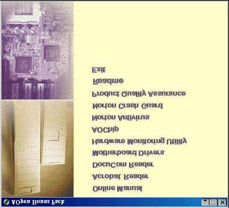
4 Over-current Protection Hardware Monitoring Resettable Fuse Year 2000 (Y2K) uF Low ESR Capacitor Layout (Frequency Isolation Wall) Driver and Utility...57 Autorun Menu from Bonus CD Disc Installing Windows Installing Windows Installing Windows 98 SE & Windows Installing VIA 4 in 1 Driver Installing Onboard Sound Driver Installing Hardware Monitoring Utility...64 ACPI Suspend to Hard Drive ACPI Suspend to RAM (STR)... 72
5 AWARD BIOS...74 Enter BIOS Setup Change Language Standard CMOS Setup BIOS Features Setup Chipset Features Setup Power Management Setup PNP/PCI Configuration Setup Load Setup Defaults Load Turbo Defaults Integrated Peripherals Password Setting IDE HDD Auto Detection Save & Exit Setup Load EEPROM Default Save EEPROM Default
6 Exit without Saving NCR SCSI BIOS and Drivers BIOS Upgrade Overclocking VGA and HDD Glossary AC ACPI (Advanced Configuration & Power Interface) AGP (Accelerated Graphic Port) AMR (Audio/Modem Riser) AOpen Bonus Pack CD APM ATA/ ATA/ BIOS (Basic Input/Output System) Bus Master IDE (DMA mode)
7 CODEC (Coding and Decoding) DIMM (Dual In Line Memory Module) ECC (Error Checking and Correction) EDO (Extended Data Output) Memory EEPROM (Electronic Erasable Programmable ROM) EPROM (Erasable Programmable ROM) FCC DoC (Declaration of Conformity) FC-PGA Flash ROM FSB (Front Side Bus) Clock I2C Bus P Parity Bit PBSRAM (Pipelined Burst SRAM) PC100 DIMM PC133 DIMM
8 PDF Format PnP (Plug and Play) POST (Power-On Self Test) RDRAM (Rambus DRAM) RIMM SDRAM (Synchronous DRAM) SIMM (Single In Line Memory Module) SMBus (System Management Bus) SPD (Serial Presence Detect) Ultra DMA/ USB (Universal Serial Bus) ZIP file Troubleshooting Technical Support Part Number and Serial Number Model name and BIOS version
9 !"# $% $ $#$ #$#$$ % &$ $ #$ #$ ' $
10 $ #('$ ## $# 1)"* 2 )+# #,)- 3 " " 4 " ).$$#" 5 " / " 6 "!' " 7 01!)++ $ 8 + "* ( # 9 10 )$ +#, ) *#
\"' 7 @@) \" \"33!' 6<1.+$ 7)83/\"$ 699:%+!\"' \"*\" +# 7 = 5$ 0 0 / \" \" # \"699) +$! #0 1.")
11 " 56& + 01!)+ 2' 21 2' $1; /? ) 2 2' $ " : +$$ *+! >88). 59&>599 +$ : + "*#$ 5&3>&9+!>")"' " "33!' 6<1.+$ 7)83/"$ 699:%+!"' "*" +# 7 = 5$ 0 0 / " " # "699) +$! # " "+
12 % -.&/ &!"#$ "'' " '* $ -%(/%( &( '&. +, -%(.!"#(#!" +,*' #$ %& '$ %( &( ) * 0 " ")*'
13 Hardware $ A$ Electrostatic discharge (ESD) can damage your processor, disk drives, expansion boards, and other components. Always observe the following precautions before you install a system component. 1.Do not remove a component from its protective packaging until you are ready to install it. 2.Wear a wrist ground strap and attach it to a metal part of the system unit before handling a component. If a wrist strap is not available, maintain contact with the system unit throughout any procedure requiring ESD protection.
14 ! / ' 2 34 B "+ # "+ $ 6 # $ "$ & /$ 2& 91 56$&09 56 #$60& <" /$ ' 2& When should I Clear CMOS? 1. Boot fail because of overclocking 2. Forget password 3. Troubleshooting

15 " $$" )))+' 9C"*! "* #$"*'
16 " # $ "* 90$% )# # $ & 756! * Some CPU fans do not have sensor pin, so that cannot support fan monitoring.
17 "%& "*7)+' $ "* 0 "* ( #!)+ $ A$ "*..2 A$ 0 # "* 0$ "+ # -. &/ " /1"","""8 /% / "*7)+ "* ( "* - 9*,# "* -
18 "$' ( "*A$ 0 # "* ( #!)+ $ A$ %* % 6<D&D&<D9D9<DD<D<D<<D8D8<DCDC<D4D 884C< <6666&66<6&6&6996 6<:% VIA 694X chipset supports maximum 133MHz FSB and 66MHz AGP clock, higher clock setting may cause serious system damage. If your system hangs or fails to boot because of overclocking, simply use <Home> key to restore the default setting (233MHz).
19 % -. * EEE<.,+' 9C- 6:F <D EEE<<.,+' 9C- 6:F <<D EEE8.,+' 9C- 6:F 8D EEE88C.!,+' 9C- 699:F <D EEEC.,+' 9C- 6:F CD EEEC99.!,+' 9C- 699:F <<D EEE488.!,+' 9C- 699:F 8D EEE<.,+' 9C- 6:F <D EEE<.,+' 9C- 6:F <D EEE<<.,+' 9C- 6:F <<D EEE8.,+' 9C- 6:F 8D EEE88C.!,+' 9C- 699:F <D EEEC.,+' 9C- 6:F CD EEEC99.!,+' 9C- 699:F <<D EEE488.!,+' 9C- 699:F 8D
20 )*+),$+- A$ $ # $") +!'? #$ '# ' :6$:6 :6$:6 :6$:6 :6$:6
21 !" -.* %2+)4 " & '10 &/ ")D&D9 9/ ")D&D9D 9/ ' 66& 9C9 C8 ")D&D9D / ")D9D / ' 6<< 94C< CC< ")D9D VIA 694X chipset supports maximum 133MHz FSB and 66MHz AGP clock, higher clock setting may cause serious system damage.
22 ,,+,)".(% A$ "*#$ %;0 : :6 "$$ 60& 60& " &09 60& # $ # # $ # # $ #!"
23 6840$)' #"699 #$ 6<?!#+$$ The driving capability of new generation chipset is limited due to the lack of a memory buffer (to improve performance). This makes DRAM chip count an important factor to take into consideration when you install DIMMs. Unfortunately, there is no way that the BIOS can identify the correct chip count, you need to # calculate the chip count by yourself. The simple rule is: %&!"##$%% %& %%. %&
24 ) 8&'2 # 0'+ # To identify 2-clock and 4-clock DIMM, you may check if there are traces connected to the golden finger pins 79 and 163 of the SDRAM. If there are traces, the SDRAM is probably 4-clock; otherwise, it is 2-clock. To identify single-side or double-side DIMM, check golden finger pin 114 and pin 129. If there are traces connected to pin 114 and pin 129, the DIMM is probably double-side; otherwise, it is single-side.
25 -/ $ $$ #) '$ +$ $ # 1.
26 $ &%)*)% '( '#,- + #&. #/*)% -!
27 $ 1.' #'$ ' $$) # + $G+$!)++ $ ")= 1. ' $ # $ )/ ;0 " +$,+6- # +$,+9- # 1 $ # / ) &0$ $ 0$ ' <*

28 /.30 /$ $$# &0$ ' #$ +1 1'6 #, % #,23 45% 01
29 /0/-4( /# $ "$ $ ' '*+ ' $$ 0 $ " # $ )!)++ $G G"2 # HI # #$ 0 "$
'98 &%)#8 :%")
30 2 $%%( " 90$$$# 0$). $$# "). =-//-).6! $6 2 # # +,-,9- &%)'98 &%)#8 :% +,&-,6-
31 ).6' $# ).& #. $$). ' ) ' #1))>. ' " $ A$ #). $ #'"# The specification of the IDE cable is a maximum of 46cm (18 inches), make sure your cable does not exceed this length. For better signal quality, it is recommended to set the far end side device to master mode and follow the suggested sequence to install your new device. Please refer to above diagram.
32 $$>88). ).) ).680 # # ' / 0-;1 ;/)3* ) 9 & 8,6>8-D&# J99!> ) ,6>949-D&# J<&!> ) & 9 4 &,6>&-D&# J49!> ) ,6>64-D&# J666!> ) 9 6&,6>6&-D&# J688!> ,6>4-D&# J68!> 6 9 < 6<,6>6<-D&# J699!> & 9 6&,6>6&-D&# J688!> *>99 9 6&,6>6&-D&# D&J99!> *>88 9 & 8,6>8-D&# D&J88!> *>6 & &,6>-D&# D&J6!> To achieve the best performance of Ultra DMA/66 hard disks, a special &$"!'( for Ultra DMA/66 is required..
33 / ) $$ $$ 1$'23< " " $$ ' $ $$:+),66<&K$& -+K0),<8K$- ) "!)+ + $*& ' #$ ) #
34 ! $ $ $$2' ) D D $$ + ) $ # $ 0$ *"& <'!"#$ #
35 ! 9(2:!3? "$ # # $ $$# D D!"$ ' '?' 1 ;/ '=
36 ! 9( 2 $ /$ >$ # #$ ' $# $ > D B# # ## $ # ' #$ $$#! D D $$ 2' *$# D # #D ' 1 ;/ 2 $ $ $ " $ # '=
37 !15 1/;8 #2' ' 2' 1;# '$ $$ 1; 21 #,$#) - '. # ' ' ' $ # ; 8/# ( $$ 1; # 7@!/ =0 & "
38 '= /

39 3/<5/<%8 $$/?? 0$ 9 $$$# # > $ #? 6 & 88:%' 88:% D# D&J<&4!> &88:%?' 88:%'# 88:%D# DJ6<8!>

40 / -5/+ -8 $$! "*$$ $ A $ $ "* $,"."- ( $ $ $ ".", # 56&- $ ; # ")
41 ** )> +>&K #+>& $"6"& *+!"3C? $ ' $,6') % / &1 A0= '5 '6 '" /"/..D +$ '.$ $. /"/ ">$ $# '" $
42 %%" $$*+!$ '$ 0 2$$ # $ % ; % #
43 )2 9+9! 9 "3C56& 6446 "."$)# # #$ 5 6 /= 5 6 )=
44 / =-. " "7 # " 5 6 & & *
45 / )> $60&'/"/ $90'- ' # # $ # '' 5 '/"/ & & '-231' 14
46 7=/=; /.?.? #!"B%"B" 5 6 & & *
47 (& 1 1 $..$ # # "*"++ $ # ", '- ' $ $ $ )# #"+# #A "+.. # ; )/ =09 0 *' 9- *;1--. ' /# $ "$ $ # #$ #!'$#..
48 !4& " #$$$ /997><7>6&7$ $$#: "* <7 "*, D$ &7-' <7 $ $$"* 0 $ A 997><7>6&7$ $$#$ 0 $ ; 9-/ !2- =09)04!2- =09)04 /= >/ 9 -/ * - %!
49 #$ Although we have implemented protection circuit try to prevent any human operating mistake, there is still certain risk that CPU, memory, HDD, add-on cards installed on this motherboard may be damaged because of component failure, human operating error or unknown nature reason. % & & & '(
50 #0 $ # ### ## L' "* $ )# # L $ : *# / %;1 %! 0)1!
51 -9$ K #*+!$$ 0 ', A$ - $ 2 D$ ' $ A
52 )>>>5)?8 B&K#$ # $ ## D$ & ", "'-A6&4# "+ $ "# "+ & * #L ' 633C!6334!6333!63 # B&K$! $$' +!)+" ) ' $ $# "# $$ + +!)+ #!)+,"- #
53 !"#$% %#&& ', #< -!)+' $ > )!)+' $ "+ # "+ # # $ ' $!)+# $$ $ # > B&K$,;+1L $-! # $," '34- ">"+ #;)1= ) 9C6A--.// -/ /))).3/
54 @>>$102-% (#.+$,1.( + - ( # $ #$#"*$ $ $ '0 ( D$ ;# $ 5@--),6-$ #"*$
55 $ "* ' # # $ "*, ))) '-#$"* &7 6487&67 &47! $ #+ +$ #69 D64 $$
2I+ $ $ $ ( # ' ( # L$ # D$ ' (, # $ -''")
56 1(5$' ( 8 ( #$ $ # '# $ ' $ "* ' # $ $ L MM M(MMM MM MMMMM MMM )2I+ $ $ $ ( # ' ( # L$ # D$ ' (, # $ -'' $,6>6 + -
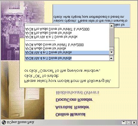
57 Driver and Utility $!"BL ##! # # #$ #,234- ## #$ # L Please follow recommended procedure to install Windows 95 and Windows 98.
58 / B!"" #
59 6 & 9 L#0 D $? )23<+& &66&6&6&6 *+!$$ # *+!+*./. ) 7)6 7)?7D )N 7) $ #$ #) 0
60 0*A 6 & 9 < L#0 D $?. *+!"!)++ $G) $ G"$*+!'!)+#$ )N )234## ) 7)6 7)?7D )N 7) $ #$ #) 0
61 0*A2B 0)>>> )# 2O34+.2&# 006 )N ") # #$ $ # * 2O34+.#$ ).!? # # 7) ) 6 P $P>> > $P>> > >6& D

62 7/ 4 B 7)6,).! 7)?)N 7) #-!'" If you want to uninstall the VIA AGP Vxd driver, please remove the AGP card driver first. Otherwise, the screen may go black at rebooting after the un-installation. Installing this Bus Master IDE driver may cause Suspend to Hard Drive failure.
63 ! "3C"." 7)+! $ B!'"

64 #0 "( B: *#"* $ # #$ #!)+#
65 /% #4 ")+$ : # #2$ # ) # ',# # -' # #$ ; D $ # #' # ' 2$ #$$ )# #8!## 8!:$ # #
66 + "' >/ ($ )*+ "' ($ *)9/ )-/ )
67 6 & D!+ 5= -/3)0)?-= 6.D Q?,EQ234 & 234R$ " G + + G+# +#Q; Q "'Q: Q Q. : +$$Q Q$$#Q "' Q Q#R Q: QQ!Q; $ # $ $ # Q+#QQ+Q + Q: QQ$$#Q 6 " +F7:# )# '#234#,689&-$ QF>,-,3Q $ ' # 8!68!7? # 4! $ # $ #
68 )# $234$ QF>,-,/Q # $ $#$ & 9 # BR #$ ")+$ 0: "'Q+G+G +#Q #6 ' # R # S #% $ '
69 6Q*?Q? $ :K.B@1"1@":);. +2. )"+ 2);2+ "*.;7.+);.." + Q!#Q Q";"Q ' #Q6Q QQ' Q6Q + &+ Q; : Q " 234,) Q""Q Q/ 0"Q- 9 # " +QF7:./.>"> Q
70 6Q*?Q? $ :K.B@1"1@":);. +2. )"+ 2);2+ "*.;7.+);.." ")); ' Q# Q6QQQ' Q&Q "02" means Windows 98 is ACPI acknowledged but the ACPI function is disabled. +
71 &+ Q; : Q " 234,) Q/ 0"Q1>G""Q- 9 # Q; : QQ Q <"'QKQ Currently we found only ATI 3D Rage Pro AGP card would support ACPI suspend to disk. Please refer to AOpen web site for latest update.
72 /% -/ 5.-8 $$")+$ 2# #' # 234$ #$$+$ # ' # # +$ : ( $ $$ +$ : ( $ + 0)1"18) 0)1 /*'!'$ # 997 >-) )*+ 0)1"18) /*' ' ' 0)1 >-) ' '
73 $ ")+$ $ $ P 6 & ")+ ( " #234 # ") +$ : $234") 7)6 $$ #! 6 & 9 "!)+!)++ $G G")P.!)++ $G G")+$ #$ P+9?" G + H!IH+#I $ #' $ #
74 AWARD BIOS +# $ #!)++ $ # # $ 6&4# "+,# "$ $ -!)+ $ $ T G +, 0+ - # Because the BIOS code is the most often changed part of the motherboard design, the BIOS information contained in this manual may be different with actual BIOS that come with your motherboard.
75 2!% % # A$!)++ $$ T G+, 0+ -" Q1+ $ Q $$ Please avoid of using "Load Turbo Defaults", unless you are sure your system components (CPU, DRAM, HDD, etc.) are good enough for turbo setting.
76 1 :; B #$ T3G $!)+$ $.? 5$ "

77 !% Q+"++ $Q # $ '#$ * ' # T*$GTG
78 $ T*$GTG # $ T*$GTG &#'
79 ;0 * ; # ).'$ ## $$ $ +% ; "# ; : +"# 0$ "# : 1F ; + $ ' Auto,!)+# $ :,:' -+, 0+ -) #$ :$ # User+ None : # )."## For an IDE hard disk, we recommend that you use the "IDE HDD Auto Detection" to enter the drive specifications automatically. See the section "IDE HDD Auto Detection".
80 ' ; 1! 1 ). # ' $# <&4! $ 1!',1!- 1! ).' ' $#$$$# <&4!; : 1! 1!
81 > ; 98K!<&<Q 6&!<&<Q C&K!9<Q 6!9<Q &44!9<Q $$# #$ #$ $$ #! $ #$.?>7?.?+ " 7?# "? # "?4
82 ! +/ ;..! K #!'!'>K # $ # # $ 0+,+-
+ +")
83 !$% $$ # $Q!)+ + $Q
84 "# $%!)<//. + $. $ $ # ' # $$ ' $ # $$ 0 $ $! WARNING! Disk Boot Sector is to be modified Type "Y" to accept write, or "N" to abort write Award Software, Inc.
85 "#&'?/-..$ # $ # # # $ "#()*&+% %6- # 1&"."" ' -./. "#,-# -))1=. )))"* ;
86 "#.+/0 H-.9/3 ;). $ $ $+#'$$ # ' "##),# 1 # ' ).
87 "#1 I/- "+"+) "+"+) "" "" "" +"+).+"+) +"+) +"+)" +"+)" "# 1+>F)" $ #$ # # $ ( ') P "P# P#.P+ # P+ # 1+P1+6& F$P).?F) "#/# 90> #$$$# D$ #. $$#,!-#! 0
88 "#(#+ %0.. + # ' # $$# + "#(,)+ %1-. + $ ) ' #$+ $ # ' #$ "# 2&+ '100, + $ # -. $$#>."" ' )=.
89 "#3% ;01-* /.. ' # $ $# "#32 ;01-* & 6< & & 9 # $ $ ' #' 30 characters/sec
90 "# ;01-0 &< < C< 6 $ # # ' #', $ ' #' - #$ # &<< C<6 "# -0/ + $ 0)1$ +#!)+ $$$'# #$ +# $$ # # # $ #!)+ $ #$ + R#$ #A$ T. G
91 "#"2 4 ",!& /.. ")7?' $,$ - $ $, $ $#- # $# $ $ "),.?7 $ -) ")7?.?>7 $ # "# *' #' +>& ;0+>& + +>&## %+>&$ # #% 8!
92 "#/)% 9/ -/. # $ + "# "/! " 9 7?!)++ $# $#!)+. # $
93 "#7889##/ "#889###/ "#8889:##/ "#6889;##/ "#7889##/ "#889###/ ( 9. D D$! # $ # ' $ )# ' The F000 and E000 segments are always shadowed because BIOS code occupies these areas.

94 %$% Q"$ + $Q $ $ # $ Make sure you fully understand the items contained in this menu before you try to change anything. You may change the parameter settings to improve system performance. However, it may cause your system to be unstable if the setting is not correct for your system configuration.
95 #+82<3 % #+*2:3 % #+62=3 % /.,5*' " ;1/ +6 H*'5/)I ' +4 ; #3 ) *'/-0 + #'A & +$ &' 9 )## $ &9
96 #3 + *'-. "*"1K "*"1KU99 "*"1KV99 "' ")'D&D9D $ 5&3>5&9 +!>")' # # '$# "*"1K099"*"1K"* "1KV99#"*0")"1K"*"1K"*V")"1K :6$,:6 -.* % -. " "/ *'-. &/ / / ' 66& 9C9 / / ' 6<< 94C< "* "*V") "*0") "* "*V") "*0") "* "*V") "*0") "* "*0") "* C8 66& &< 6<<
97 #!<= 9<5 '10+ $ # # # $ )+ $ > )+ #;# #$$ )> ##39$ )*<;/ /. + #% "* /= #"- 0)1" -=. +. #!)+ 0, #8K- # $ : #$ # # #
98 # 3 -! *'-=. # 7! #4 &' #A#?$$ 6/&// #4> &F # %? 4689&86&4?$$
99 #( %'- ). D"* # # # : ## "* $ 2 $ $# #' #+ -. '$ $.) -1 ;##L #( % %!- # "* #
100 #( %% %!/ 6979<7#<7 67 $$ ' D"*B##A# <767 $$, $ - ' +!' 10 ))0 10% High CPU core voltage may be able to increase CPU speed for overclocking, but you may damage the CPU or reduce the CPU lifecycle.
101 #( % - "*$ # )# + $"*+$ "* "*"'# ' #"* #(+#1 %-.I/-0 # D ',+!'- 884C<49966< # # "* 6666&66<6&6& $ #"*$ 69966<:% #(+3 %-.* ) )) )," - 6<&&<99<.D,!- ( # # <<<<8 " >! ( # 9<D 8<CC<4
102 #( % "*+$ $H"*"' ( #IH"*"'I

103 0 % + $ # +
104 / %"# "/-/. )#+") #. # D$ )#+ # / %/ % 9'/1/ D+ + * # $ $ 0 + )=$ + * # $ ' F / =0 )/ +99/ < D
105 / % - '/ =0 ' B ; )QD+ Q # $, - $ D$ $"* ' / % 00! 33' #!'+ 7>:+B;"V!' ' 7>:+B;"V!'!)+ ++$$ 7+B;":+B;"$$!'+ #+,$# $ # 7? / %" ")/ ;0 # $ #$ +6 +6,+- +$ +9+$ +9,+-
106 / %- / =0' 6+ & & 84 6&9 6: # $ # +# # #, - # )N,)>- / % )/ ' # $ 6+ # +$ & & 84 6&9 6:
107 / %!// +99/ 6W 6< $ #$ # ).: $ $ $ $ #,% +#+$ - / %0900-$3, 333=0<*; $ ")$$ # # 2 0)- $ )0 $ $ +$ ) $ $ # +$ ) $ # "/)/33$ # $ +$
108 / %$+" <./". ")$ &&")$$ # ")")' $ # # / %$+ <./*)1 $ #$ # 2'. *$ / %$+), <./ $ #$ # 1;2' *$.
109 / %$+3 <./*;;1. 2' *$ ' ' $ $ ## $ 0 $ $$) ' $ ## $ > $ # "2' *$ / %0 23'/4 $ # ' $## B 096 H<./*;;1I / % ;1211))4 $ # ' $## B PP0 H<./*;;1I &9P<3P<3
110 / % 4 / %)? / %!?# / %"!& ; 7?1": ") $ / %$33 <* /# $ *->0 "$ $ + ' ' *+ ' $$ 0 $ + # #$ 0 "$ S # $ 0# ) +$ # $ 0$ 0
111 / %",3 10";* ; )N906<;) $ $ ;#$$ '
112 / %"3.: * / %"3.6 < / %"3.=)* / %"3.5#+ / %"3.;)< / %"3.73 / %"3.@"3.*3 / %"3.<83 / %"3.<<3 / %"3.<*2* / %"3.<: / %"3.<6!+ / %"3.<=3 "*H2'64 # )N906< $ $ + #
+\") # # $$ #")
113 ;+ % ;>")"+ $# )+") # # $$ # $Q;>")"Q
114 ,2"0%," "/) B ; ;# #!)+ +, 0+ -)# $ #,23<- Yes!)+ #,7?>).+"+)- # #$ #,2"0%3 *)-)/ 0 + $# # )N )+") + 0
115 "*H))/ 1 #)+ ")>)+ )#)+$ ( $ )N$$ )N -0"!)+ )N #)+ ","/' ") # $, D $")).-
116 ,2"0% 8%,2"0% <%,2"0% :%,2"0% =%,2"0% 5%,2"0% ;% (, 1 #)+ )#)+$ ( $ $$ -0"!)+ #)+ ","/' ") (,2"0%("$00 %"< "*") 33.
117 ,2"0%"% "0/1-)/. ")#,2"0%" 8$$ "')< ") # ) < ). "),2"0%" "0;/)-/ # #. 7)<48$,) "))+ - #")# )+ # # )+ $#$
118 ,2"0%"A*A<3 "J6--))J5 *0.? # )? D $ ")X&?,2"0%4 <$$ &')5<? 6 <.,2"0%4 <$3 &')5<? 6 *.
119 ,2"0%%"3.0( ))/"*H3% # )N*+!.,2"0%%"3.0 4 ))/"*H3!& # )N7?.,2"0% ("3. ' 1%)"*H # )N 9<C3666;>
120 ,2"0%<"3.,B,2"0%*"3.,B,2"0%:"3.,B,2"0%6"3.,B 5"*H 9<8C3666 6&66< $$ # )N# 0 ") )# # # ) $#$ $ #
121 1% Q1+ $ Q$$% $# $ $ # ->3-/K -1=0,=0)/ 1/3-I0-/=) /G 3)G2 $ Q1+ $ Q )# # $ ## # $ Q!)+ + $QQ"$ + $Q
122 1.9 Q1 Q$ $ Q1+ $ Q) $ $ $ $ #$# #, D$ # #7? )-%);=)//09/030/ )/ 1)/) 1/ $ $ #9Y<Y $ $ $$
 $ Q")
123 % $$ # $Q) $ Q $# )>
124 "%"& "%"& /10". $ # ). $#). "%"&0 "3-' ).$. "%"&!+ "+-.' '$ #. 0 $ ). D $ $$
125 "% " "%" "% " "%" 10')" 6 & 9 + Auto :$ 0 ) $ : D$ P 99!> 6<&!> &49!> 9 666!> 688!>)#' $ ####
126 "% ( "%( "% ( "%( 10')%' # >88 $$ # ' #$#). "%"# "/)0) )# ")7?? ")+ #? $# "% //.
127 "%)% /-0. +! $ $. + "%"2 / ",) +! $ )> )) &&:&:&8: &4: "%"3. / "*H- +! $ )N )N<)NC)N3 )N6
128 "% / '- 6 &9 +! $ "% (968<"2 '%5", )) )> )) 9099: $ : 9&09&9: : "%-# /= + $ /= # / #$$#' $$#'. $ " # $
129 "%-< "%-* /= 5 94>)N &4>)N9 9.4>)N &.4>)N9 # $ $ If you are using network card, make sure that the IRQ do not conflict.
130 "%(3* %*;6' + :+) +K) # Q+ &Q #$ # $& P / + $&$ +"* D 66<K A"* D 63&K "%"3#' "*/-/? : $ D:$ D) ;#$ D 0
131 "%3'C' *?K;?-> :: :1 1: 11 D, -D,- *& ) #) "%- /= $ $ 9!">)NC $ 9C4>)NC &C4>)N< If you are using an I/O card with a parallel port, make sure that the addresses and IRQ do not conflict.
132 "%- /= ' ; +."..">. # $ $ $ +,+!0 -.,. -.",.D - 2/ / -/4 + )!+>&$ 2//- 4. $ $$# # > >$ $ 2?/ 4."$$1.,1. - $ $ "%& ( ' %)' 9 6 #."
133 "%& ;0.6C.63 #. $ "%( /%. *+!
134 "%(D- %A0=. # *+!' #!)+ ' # #' # # *+!' # + #R *+! $ # You cannot use both USB driver and USB legacy keyboard at the same time. Disable "USB Keyboard Support" if you have USB driver in the operating system. "% 3# '*/-/ "3C ). L'$$ #
135 0 $ % #$ )# $ # $$ $ + $ $P 6 & 9 $$#$ #$B$ $4$ 2 ##$ #$$ ' $ D #$ $$ D$$ 0#$ #$$ $ $ # # $$ $$ $ $# $
136 2#/ )## ). # $ Q+"++ $Q#
137 # $ #). + ). $ )#' $ # $ #) $ ' ' ) 0 $ $# # #$ A # +"++ $
138 4B2:% # "+ + $
139 122-!.D $Q1+ $ QQ1 Q## Q+.. Q #.. # 422-! B# #.. "+ # $ ## Q1.. Q 2:04 * D+ $ "+ $ # ;-! 4 $!)+ ;"<9"46+"+)!)+,$$+296+>&- #!)+#+"+) +"+)!)+ # $ ## ;"+"+)#$ # # ;"<9"46+"+)
140 !"% $.# #!)+# #$# $ $ 6?!)+$ $$ R D$ /963./.) +$$#' # & # + # #,.948- ) <&K #$ 9.D PG/963 ;/339 /+* # $ T G!)+ $" Q1+ $ Q H+ =.D+ $I E The upgrade of new BIOS will permanently replace your original BIOS content after flashing. The original BIOS setting and Win95/Win98 PnP information will be refreshed and you probably need to re-configure your system.
141 Overclocking #$ # $$ R ( #$# # # $ # '$ # $ # ' Q ' Q ' $ D5'+F"*'! ' 5@'+F "*' 5@'+F $$ ( $ $
142 The design of this product follows CPU and chipset vendor's design guideline. Any attempts to push beyond product specification are not recommended and you are taking your own risk to damage your system or important data. Before doing overclocking, you must make sure your components are able to tolerate such abnormal setting, especially CPU, memory, hard disks, and AGP VGA cards. Note that overclocking may also cause thermal problem. Please make sure that the cooling fan and the heatsink were adequate to dissipate excessive heat that's generated by overclocking the CPU.
143 7</ # 7?: ' #$ ' $ # # '!& + $P>>$ > > $> '>> 0 $P>>$ > > $> '>>0
144 Glossary!#"3C$ $ > $$ ".")> # ' #"3C'+ $ $ $ > ") $ $ "3C,633C-) $ # '$ $ # #$!)+ $ $ )>$ $ $ #,2 34- ") / #$ $
145 ? 0$ 9$?$$# # > $ #? 88:%'&/? 88:%D# D&J<&4!>? / 88:%D# DJ6<8!>$ $# $$/? #/8",) 4&-/8>/8,7)83D- 6333! ".""3C> $ $,- "#!$% $ $ *' ")!)+$ $ +$ : D$ $
146 &'' >88 *>99 ) &688!>DJ88!> >88 # $ >88). &()) >6 ).$ $>6 >88'#,6>-D&# D&J6!> >6# $ 40 ). >88 #"*#!"*+!!)+ # >$.!)+ )$>$ ) $ $ $#$ # (!)+ #
147 #!!%,% ), )>-). ( "* ). ' "* ). > # $"* "* $ # #). B ). ).:$$ ). "%, % ;#"." )$"3C> %%- + )' 6840$$$80) "! # )1 ) #+$ 997; ) # >.#$ <7 +),,$."" 4.""80. #."" $ ' #$."" # 0 # 0 $# # 0
148 ,%",. %" +. ## #, -*' 0 #$ $ 0 #. # D # # $$ ',,",,!/ /" '.!.. 0$ # # +%.. $..A$ 0 #0,",!/ /"!)+..# #0,*7-)!)+ $ #. # *7 0$ ' 0%% + "$ "".) )B $, -$$#" $ #
149 01 " $"$"0? $' ) )))"*)$ +K9C' ( ' 9C ) $"0?9C"*$ 6 "* 0!" 0$ # )!)+$ # # #!!)+% 8K!&<8K!,&-$ /< $ &<8K!,&-;% /8",) 4&-/92,) 46-0*#0* #!$ +!"' "* D ' "* 'J"*+!"'D"*"' 2#! + +!
150 (34 693,) $ $ $ *' $ *+!693$$<6> '1; +# $# 6$# # # $# #$ $# A Q6Q # 2 D # Q6Q $# #* #!* +' C"* ( N2,N0D68J8-!+ # # N2"* $ ( ;# ' #+!+ 1&, &- +' C"*+6 +' 9C"*!+ ())% +)$$6:%"*+!'
151 (33% +)$$699:%"*+!' %00 $ $# 2*D1DW B # ).; $ # $0,) - + $!)+$ #,23<- #!)+$ # # $ # )N>> # # #!)+$ # " # "))+ #$ "*&1"*&!!)+ $ $ 0 ##
152 % /!% # # # + $ ) 4&# $$ 680$ # D 9& #)' 640$ # $$ # #) # # $D68 *%*+!% + ' "*,. # '-)! $)$ 997$ $#$$0+),<7-N66338 **- + +)' #C&0$# "! # + )1 +) #. $$9&0+) $
153 *#!*+! #! +! )&")0 $ $, $ # )"- D$ '' A$ 0 +!#6K> "*# > *%*!% +.. ))+ # $$ + #!)+ )) 5%33 *' )> # ). *>99 ) & 688!>D&J99!>
154 5*#5!*#! *+!0$ $ $ $ > $ $ $, 6>-' # A#' $ 2*+! $ D '$ #" 6 $ % %$ K*;F),$P>>$' >-+ $ # 2);F),$P>>%$>-
155 Troubleshooting + $ $ "$ 0 7?)."6"&$ ' A$ " "+ ; D
156 " ) 7? #' # C) $ ' $ $$#"*' $$ # ; D $ $# # $ $$# # $
157 " " ' $#Z $#7? C) T"GTG' # $ T G # " ' # Z C) ) #$ #' # ; D
158 " # $ T G!)+ $ " H1+ $ I # 0 ). " ' # #Z C) $ # ). : 0$ # 234.
159 Technical Support " '$ $$ $#: $ 0 ## # # 2 # $ ' $ 2# $ $ (# ' ## E $ +$$ 1 2 //'/ ' #' A$ $ $P>>$ > >>> ;)*2 >> $# $ #" $P>>$ > > $>
160 H N, ( #' N -## $ $P>>$ > >(> 9/ 39" ' $!)+># $P>>$ > >> 9)&B$ $# #$$ $ $ $P>>$ > > $> /-)=),*))2 $ #'## # #$ # $ # D ##
+>\"*$ \"! D$ P,$5((5565$,$5$$L(AL")
161 7 /-%) $ $ # #$ /1=)/1=">)/ # $ ; + $ B $')+>"*$ "! D$ P,$5((5565$,$5$$L(AL
162 !)+ $$,+ - D$ P *565&$ ) #!)+.D 6 "$#[6334+ ) *56!)+
163 <=%))$$$**+ 1+ # /) %))$$$**+*$)%))%*%+ :/) %)),**+*$)%))%,*%+ /) %))$**+*$)%))%$*%+ &1/ %))$$$*+*-)%))%-*%+ 13 /)%))$$$**+*)%))%*%+ ; % 8<04&C03844 / ) V96C908<03<68 /,48-C<<09C<0969 ;9/,448-&0& &1/0 V3,-&6&06<C0C
MX34 Online Manual MX34
 MX34 MX34...1 What s in this manual...2 Before You Start...9 Quick Installation Procedure... 10 Motherboard Map... 11 Block Diagram... 12 Hardware...13 JP14 Clear CMOS... 14 CPU Slot... 15 CPU and Housing
MX3W Pro Online Manual MX3W Pro
 MX3W Pro MX3W Pro...1 What s in this manual...2 Before You Start...9 Quick Installation Procedure... 10 Motherboard Map... 11 Models of MX3W Pro Series...12 Block Diagram... 13 Hardware...14 JP14 Clear
AX63 Pro Online Manual AX63 Pro
 AX63 Pro !"# $% $ $#$ #$#$$ % &$ $ #$ #$ ' $ $ #('$ ## $# 1)"* 2 )+# #,)- 3 " " 4 " ).$$#" 5 " / " 6 "!' " 7 01!)++ $ 8 + "* ( # 9 10 )$ +#,234-11 ) *# 56" "+! #0 &!)+ 7 2' 01!)+ +!01' 9 21 2' $1< 2 2'
DOC. NO.: AX34U-OL-E0108A
 Overview Hardware Installation Drivers & Utilities AWARD BIOS Setup Glossary Troubleshooting & Technical Support 1 AX34-U DOC. NO.: AX34U-OL-E0108A What s in this manual AX34-U...1 What s in this manual...2
DOC. NO.: MX34U-OL-E0109A
 Overview Hardware Installation Drivers & Utilities AWARD BIOS Setup Glossary Troubleshooting & Technical Support MX34-U Online Manual MX34-U DOC. NO.: MX34U-OL-E0109A 1 What s in this manual MX34-U...1
DOC. NO.: AK OL-E0010A
 AK73-1394 Overview Hardware Installation Drivers & Utilities AWARD BIOS Setup DOC. NO.: AK731394-OL-E0010A 1 Technical Support Glossary Troubleshooting & What s in this manual AK73-1394...1 What s in this
MX3W DOC. NO. : MX3W-OL-E0001A. A Open
 MX3W DOC. NO. : MX3W-OL-E0001A 1 Before You Start This is in PDF format, we recommend using Adobe Acrobat Reader 4.0 for online viewing, it is included in Bonus CD disc or you can get free download from
TABLE OF CONTENTS 1. INTRODUCTION 2. SPECIFICATION 3. HARDWARE INSTALLATION 6EX 1.1. PREFACE KEY FEATURES PERFORMANCE LIST...
 6EX TABLE OF CONTENTS 1. INTRODUCTION 1.1. PREFACE...1-1 1.2. KEY FEATURES...1-1 1.3. PERFORMANCE LIST...1-2 1.4. BLOCK DIAGRAM...1-3 1.5. INTRODUCE THE Pentium II Processor & AGP...1-4 1.6 What is AGP?...
hmk33 II / MK33 II(A)
") h Overview Hardware Installation Drivers & Utilities AWARD BIOS Setup DOC. NO.: MK332A-OL-E0102A 1 Technical Support Glossary Troubleshooting & What s in this manual...1 What s in this manual... 2 You
h Overview Hardware Installation Drivers & Utilities AWARD BIOS Setup DOC. NO.: MK332A-OL-E0102A 1 Technical Support Glossary Troubleshooting & What s in this manual...1 What s in this manual... 2 You
TABLE OF CONTENTS 1. INTRODUCTION 2. SPECIFICATION 3. HARDWARE INSTALLATION. Table Of Contents 1.1. PREFACE KEY FEATURES...
 Table Of Contents TABLE OF CONTENTS 1. INTRODUCTION 1.1. PREFACE...1-1 1.2. KEY FEATURES...1-1 1.3. PERFORMANCE LIST...1-2 1.4. BLOCK DIAGRAM...1-3 1.5. INTRODUCE THE Pentium II Processor & AGP...1-4 1.6.
TABLE OF CONTENTS 1. INTRODUCTION 2. SPECIFICATION 3. HARDWARE INSTALLATION 6BA
 6BA TABLE OF CONTENTS 1. INTRODUCTION 1.1. PREFACE...1-1 1.2. KEY FEATURES...1-1 1.3. PERFORMANCE LIST...1-2 1.4. BLOCK DIAGRAM...1-3 1.5. INTRODUCE THE Pentium II / III Processor...1-4 1.6. What is AGP?...1-5
User s Manual. MMX Enhanced MediaGX System Board. MMX Enhanced MediaGX System Board
 MMX Enhanced MediaGX System Board MMX Enhanced MediaGX System Board Trademarks and / or Registered trademarks are the properties of their respective owners. User s Manual IBM, PC/AT and PC/XT are trademarks
Introduction CHAPTER 1
 CHAPTER 1 Introduction The ROBO-667 all-in-one single board computer is designed to fit a high performance Pentium-III based CPU and compatible for high-end computer system with PCI/ISA Bus architecture.
TABLE OF CONTENTS 1. INTRODUCTION 1.1. PREFACE KEY FEATURES PERFORMANCE LIST BLOCK DIAGRAM...
 Table of Contents TABLE OF CONTENTS 1. INTRODUCTION 1.1. PREFACE... 1-1 1.2. KEY FEATURES... 1-1 1.3. PERFORMANCE LIST... 1-3 1.4. BLOCK DIAGRAM... 1-4 1.5. INTRODUCE THE PCI - BUS... 1-5 1.6. FEATURES...
TABLE OF CONTENTS 1. INTRODUCTION 2. SPECIFICATION 3. HARDWARE INSTALLATION 6BXDS 1.1. PREFACE KEY FEATURES...1-1
 6BXDS 1. INTRODUCTION TABLE OF CONTENTS 1.1. PREFACE...1-1 1.2. KEY FEATURES...1-1 1.3. PERFORMANCE LIST...1-2 1.4. BLOCK DIAGRAM...1-3 1.5. INTRODUCE THE Pentium II Processor...1-4 1.6. What is AGP?...1-6
TABLE OF CONTENTS 1. INTRODUCTION 2. SPECIFICATION 3. HARDWARE INSTALLATION 6EM 1.1. PREFACE KEY FEATURES PERFORMANCE LIST...
 6EM TABLE OF CONTENTS 1. INTRODUCTION 1.1. PREFACE...1-1 1.2. KEY FEATURES...1-1 1.3. PERFORMANCE LIST...1-2 1.4. BLOCK DIAGRAM...1-3 1.5. INTRODUCE THE Pentium II Processor & AGP...1-4 1.6 What is AGP?...1-6
Introduction CHAPTER 1
 CHAPTER 1 Introduction The ACTI-777 all-in-one single board computer is designed to fit a high performance Pentium-III FC-PGA based CPU and compatible for high-end computer system application with PCI/ISA
Section 3 MUST BE COMPLETED BY: 10/17
 Test Out Online Lesson 3 Schedule Section 3 MUST BE COMPLETED BY: 10/17 Section 3.1: Cases and Form Factors In this section students will explore basics about computer cases and form factors. Details about
DOC. NO.: AX4BP-OL-E0201B
 Overview Hardware Installation Drivers & Utilities AWARD BIOS Setup Glossary Troubleshooting & Technical Support AX4B / AX4B Pro Online Manual 1 AX4B / AX4B Pro DOC. NO.: AX4BP-OL-E0201B What s in this
TABLE OF CONTENTS 1. INTRODUCTION 2. SPECIFICATION 3. HARDWARE INSTALLATION. Table of Contents 1.1. PREFACE KEY FEATURES...
 Table of Contents TABLE OF CONTENTS 1. INTRODUCTION 1.1. PREFACE...1-1 1.2. KEY FEATURES...1-1 1.3. PERFORMANCE LIST...1-2 1.4. BLOCK DIAGRAM...1-3 1.5. INTRODUCE THE Pentium II/III Processor...1-4 1.6.
TABLE OF CONTENTS 1. INTRODUCTION 2. SPECIFICATION 3. HARDWARE INSTALLATION. Table of Contents 1.1. PREFACE KEY FEATHERS...
 Table of Contents TABLE OF CONTENTS 1. INTRODUCTION 1.1. PREFACE... 1-1 1.2. KEY FEATHERS... 1-1 1.3. PERFORMANCE LIST... 1-2 1.4. BLOCK DIAGRAM... 1-3 1.5. INTRODUCE THE PENTIUM II/ III PROCESSORS...
6BMM USER'S MANUAL. 3. Support Modem Ring-On. (Include internal Modem and external modem on COM A and COM B)
") USER'S MANUAL. System power on by PS/2 Mouse: First, enable this function in CMOS Setup, then you can power on the system by double clicking the right or left button of your PS/2 Mouse. 2. System power
USER'S MANUAL. System power on by PS/2 Mouse: First, enable this function in CMOS Setup, then you can power on the system by double clicking the right or left button of your PS/2 Mouse. 2. System power
FAN3 Connector AUX-IN Connector. CD-IN Connector FAN2 Connector. Intel /100 LAN Controller CPU2 FAN Connector AGP Pro Slot USB Connector
 PS/2 Mouse Connector SPP/EPP/ECP Parallel Port RJ45 0/00 LAN Jack (Optional) Speaker Out FAN3 Connector AUX-IN Connector PS/2 Keyboard Connector USB Port Port 2 Port Line-In MIC-In CD-IN Connector FAN2
Intel /100Mbps Ethernet Controller 32bit PCI Slot x2. ATI Rage XL Video Chip with 4MB Video RAM onboard 64bit PCI Slot x4
 PS/2 Mouse SPP/ECP/EPP Print Port USB RJ45 LAN JP0 CPU Terminator Jumper PS/2 Keyboard Port VGA BP (Backplane) 2 Port WOL (Wake On LAN) Intel 82559 0/00Mbps Ethernet Controller 32bit PCI Slot x2 ATI Rage
TABLE OF CONTENTS 1. INTRODUCTION 2. SPECIFICATION 3. HARDWARE INSTALLATION. Table of Contents 1.1. PREFACE KEY FEATURES...
 Table of Contents TABLE OF CONTENTS 1. INTRODUCTION 1.1. PREFACE...1-1 1.2. KEY FEATURES...1-1 1.3. PERFORMANCE LIST...1-2 1.4. BLOCK DIAGRAM...1-3 1.5. INTRODUCE THE INTEL Celeron TM Socket 370 Processor...1-4
GA - 686LX USER'S MANUAL. Pentium II Processor MAINBOARD. REV. 1 First Edition
 GA - 686LX USER'S MANUAL Pentium II Processor MAINBOARD REV. 1 First Edition GA-686LX The author assumes no responsibility for any errors or omissions which may appear in this document nor does it make
TABLE OF CONTENTS 1. INTRODUCTION 2. SPECIFICATION 3. HARDWARE INSTALLATION 6LX7 / 6LX7A 1.1. PREFACE KEY FEATHERS...
 TABLE OF CONTENTS 1. INTRODUCTION 1.1. PREFACE...1-1 1.2. KEY FEATHERS...1-1 1.3. PERFORMANCE LIST...1-3 1.4. BLOCK DIAGRAM...1-4 1.5. INTRODUCE THE INTEL Celeron TM Socket 370 Processor...1-5 1.6. WHAT
TABLE OF CONTENTS 1. INTRODUCTION 2. SPECIFICATION 3. HARDWARE INSTALLATION 6VX PREFACE KEY FEATHERS
 6VX7 TABLE OF CONTENTS 1. INTRODUCTION 1.1. PREFACE... 1-1 1.2. KEY FEATHERS... 1-1 1.3. PERFORMANCE LIST... 1-2 1.4. BLOCK DIAGRAM... 1-3 1.5. INTRODUCE THE INTEL Celeron TM Socket 370 Processor... 1-4
P4B533-X. Motherboard
 P4B533-X Motherboard C1458 2003 2 3 4 5 6 7 1 2 2 3 Jumper Mode Jumper Free (Default) 8 9 10 1-1 1-2 1-3 1-4 SB_PWR1 P4B533-X P4B533-X Onboard LED ON Standby Power OFF Powered Off 1-5 CPU_FAN1 ATX12V1
Computer Maintenance. Unit Subtitle: Motherboards. Copyright Texas Education Agency, All rights reserved. 1
 Computer Maintenance Unit Subtitle: Motherboards 1 Lesson Objectives Describe the function of the motherboard. Identify the different types of motherboards and their characteristics. Identify the main
MITAC Desktop Board PD12TI Product Guide
 MITAC Desktop Board PD12TI Product Guide Desktop Board Features This chapter briefly describes the main features of MITAC Desktop Board PD12TI. Table 1 summarizes the features of the Desktop Board. Table
ROBO-603. User's Manual
 ROBO-603 Embedded System Board User's Manual P/N: 861106030041 Version 1.0 Copyright Portwell, Inc., 2001. All rights reserved. All other brand names are registered trademarks of their respective owners.
v02.54 (C) Copyright , American Megatrends, Inc.
 Copyright , American Megatrends, Inc.") 1 Main Advanced H/W Monitor Boot Security Exit System Overview System Time System Date BIOS Version Processor Type Processor Speed Cache Size [ 14:00:09] [Fri 05/19/2006] : ConRoe865PE BIOS P1.00 : Intel
1 Main Advanced H/W Monitor Boot Security Exit System Overview System Time System Date BIOS Version Processor Type Processor Speed Cache Size [ 14:00:09] [Fri 05/19/2006] : ConRoe865PE BIOS P1.00 : Intel
MITAC Desktop Board PD10TI Product Guide
 MITAC Desktop Board PD10TI Product Guide Desktop Board Features This chapter briefly describes the main features of MITAC Desktop Board PD10TI. Table 1 summarizes the features of the Desktop Board. TABLE
Keep the work area free of clutter and clean. Food and drinks are not allowed in the work area.
 29 Chapter 3 Computer Assembly Introduction This chapter addresses the process of the computer assembly process. The ability to successfully assemble a computer is a milestone for the PC Ttechnician. It
MMX Enhanced. 586 GXM-AV Main Board. Trademarks and / or Registered trademarks are the properties of their respective owners.
 586 GXM-AV Main Board Trademarks and / or Registered trademarks are the properties of their respective owners. User s Manual Version 1.1 The Information presented in this publication has been carefully
TABLE OF CONTENTS 1. INTRODUCTION 2. SPECIFICATION 3. HARDWARE INSTALLATION 6BMM 1.1. PREFACE KEY FEATURES...1-1
 6BMM TABLE OF CONTENTS 1. INTRODUCTION 1.1. PREFACE...1-1 1.2. KEY FEATURES...1-1 1.3. PERFORMANCE LIST...1-2 1.4. BLOCK DIAGRAM...1-3 1.5. INTRODUCE THE Pentium II Processor & AGP...1-4 1.6. What is AGP?...1-6
Introduction to the Personal Computer
 Introduction to the Personal Computer 2.1 Describe a computer system A computer system consists of hardware and software components. Hardware is the physical equipment such as the case, storage drives,
The ROBO-8710VLA package should cover the following basic items
 The ROBO-8710VLA all-in-one full size single board computer is designed to fit high performance and scalable Intel Pentium 4/Celeron processors and compatible for high-end industrial computer system with
v02.54 (C) Copyright , American Megatrends, Inc.
 Copyright , American Megatrends, Inc.") 1 Main Advanced H/W Monitor Boot Security Exit System Overview System Time System Date [ 14:00:09] [Tue 02/21/2006] BIOS Version : P4i65G BIOS P1.00 Processor Type : Intel (R) Pentium (R) 4 CPU 2.40 GHz
1 Main Advanced H/W Monitor Boot Security Exit System Overview System Time System Date [ 14:00:09] [Tue 02/21/2006] BIOS Version : P4i65G BIOS P1.00 Processor Type : Intel (R) Pentium (R) 4 CPU 2.40 GHz
VI31 MAINBOARD MANUAL. Date : 1, 2002 PCB : 2.2 (for HP)
") VI31 MAINBOARD MANUAL Date : 1, 2002 PCB : 2.2 (for HP) Table of Contents Table of Contents Chapter 1 Overview The VI31 Mainboard... 1-2 Main Features... 1-3 Chapter 2 Installation Procedures Quick Reference
VI31 MAINBOARD MANUAL Date : 1, 2002 PCB : 2.2 (for HP) Table of Contents Table of Contents Chapter 1 Overview The VI31 Mainboard... 1-2 Main Features... 1-3 Chapter 2 Installation Procedures Quick Reference
Quick Start Guide. SY-6BB V1.0 Mainboard F C. Introduction. Installation. Hardware. Quick BIOS Setup. The SOYO CD
 SY-6BB V.0 Mainboard Quick Start Guide Introduction Hardware Installation Quick BIOS Setup The SOYO CD F C Tested To Comply With FCC Standards FOR HOME OR OFFICE USE POST CONSUMER 00% RECYCLED PAPER SOYO
Electronic Emission Notices
 Electronic Emission Notices Federal Communications Commission (FCC) Statement This equipment has been tested and found to comply with the limits for a Class B digital device, pursuant to Part 5 of FCC
Electronic Emission Notices
 Electronic Emission Notices Federal Communications Commission (FCC) Statement This equipment has been tested and found to comply with the limits for a Class B digital device, pursuant to Part 5 of FCC
Electronic Emission Notices
 Electronic Emission Notices Federal Communications Commission (FCC) Statement This equipment has been tested and found to comply with the limits for a Class B digital device, pursuant to Part 5 of FCC
CLK. Slot1 VIA ATX Mainboard. User s Manual 4
 2.1. Mainboard Layout Drawing CLK AGP 1 H14.318 Slot1 VIA693-133 ATX Mainboard ISA2 ISA1 User s Manual 4 2.2. Hardware Installation Steps 2.2.1. Installing System Memory The mainboard is equipped with
TABLE OF CONTENTS 1. INTRODUCTION 2. SPECIFICATION 3. HARDWARE INSTALLATION 6VMA 1.1. PREFACE KEY FEATURES...1-1
 6VMA TABLE OF CONTENTS 1. INTRODUCTION 1.1. PREFACE...1-1 1.2. KEY FEATURES...1-1 1.3. PERFORMANCE LIST...1-2 1.4. BLOCK DIAGRAM...1-3 1.5. INTRODUCE THE Pentium II / III Processor...1-4 1.6. What is AGP?...1-5
A+ Guide to Hardware: Managing, Maintaining, and Troubleshooting, 5e. Chapter 1 Introducing Hardware
 : Managing, Maintaining, and Troubleshooting, 5e Chapter 1 Introducing Hardware Objectives Learn that a computer requires both hardware and software to work Learn about the many different hardware components
System CMOS/BIOS Configuration PC Diagnostics
 System CMOS/BIOS Configuration PC Diagnostics (POST; Error Messages and Error Codes) CMOS/BIOS Complementary Metal Oxide Substrate (CMOS) A part of the motherboard that maintains system variables in static
GS-SR104 Rack Mount Server System Installation Guide
 GS-SR104 Rack Mount Server System Installation Guide 1-i INDEX 1. INTRODUCTION 1-1 1.1. PREFACE 1-1 1.2. FEATURES 1-1 2. HARDWARE INVENTORY 2-1 3. SYSTEM INSTALLATION PROCEDURES 3-1 3.1. CHASSIS COVER
Frequently Asked Question
 Appendix A Frequently Asked Question Q: How can I identify the mainboard BIOS version? A: The AOpen mainboard BIOS version appears on the upper-left corner of the POST (Power-On Self Test) screen. Normally,
FUNCTIONS OF COMPONENTS OF A PERSONAL COMPUTER
 FUNCTIONS OF COMPONENTS OF A PERSONAL COMPUTER Components of a personal computer - Summary Computer Case aluminium casing to store all components. Motherboard Central Processor Unit (CPU) Power supply
PCA-6781 ISA Celeron M Half-sized SBC with VGA/ LCD/LVDS/10/100 Ethernet/USB2.0 and SSD Startup Manual
 PCA-6781 ISA Celeron M Half-sized SBC with VGA/ LCD/LVDS/10/100 Ethernet/USB2.0 and SSD Startup Manual Packing List Specifications Before you begin installing your card, please make sure that the following
Computer Maintenance. PC Disassembly and Reassembly. Copyright Texas Education Agency, All rights reserved.
 Computer Maintenance PC Disassembly and Reassembly 1 Enabling Objectives Computer Chassis (Cases) Power Supplies Configuring the Motherboard Configuring the Connectors CPU Interfaces RAM Installing a Hard
Quick Reference This guide is written for technically qualified personnel with experience installing and configuring desktop boards.
 Intel Desktop Boards D850EMD2 and D850EMV2 Quick Reference This guide is written for technically qualified personnel with experience installing and configuring desktop boards. Before You Begin Warning
v02.54 (C) Copyright , American Megatrends, Inc.
 Copyright , American Megatrends, Inc.") 1 Main Advanced H/W Monitor Boot Security Exit System Overview System Time System Date BIOS Version Processor Type Processor Speed Microcode Update : 10FF0/41 L1 Cache Size : 128KB L2 Cache Size : 1024KB
1 Main Advanced H/W Monitor Boot Security Exit System Overview System Time System Date BIOS Version Processor Type Processor Speed Microcode Update : 10FF0/41 L1 Cache Size : 128KB L2 Cache Size : 1024KB
3.11. GREEN FUNCTION INSTALLATION PERIPHERAL DEVICE INSTALLATION BIOS CONFIGURATION 4.1. ENTERING SETUP...
 3.11. GREEN FUNCTION INSTALLATION... 3-8 3.12. PERIPHERAL DEVICE INSTALLATION... 3-8 4. BIOS CONFIGURATION 4.1. ENTERING SETUP... 4-1 4.2. CONTROL KEYS... 4-2 4.3. GETTING HELP... 4-3 4.3.1. Main Menu...
TABLE OF CONTENTS 1. INTRODUCTION 2. SPECIFICATION 3. HARDWARE INSTALLATION. Table of Contents 1.1. PREFACE KEY FEATURES...
 Table of Contents 1. INTRODUCTION TABLE OF CONTENTS 1.1. PREFACE...1-1 1.2. KEY FEATURES...1-1 1.3. PERFORMANCE LIST...1-2 1.4. BLOCK DIAGRAM...1-3 1.5. INTRODUCE THE Pentium II Processor...1-4 1.6. What
Introduction CHAPTER 1
 CHAPTER 1 Introduction The ACTI-788 all-in-one single board computer is designed to fit a high performance Celeron based CPU and compatible for high-end computer system application with PCI/ISA bus architecture.
Electronic Emission Notices
 Electronic Emission Notices Federal Communications Commission (FCC) Statement This equipment has been tested and found to comply with the limits for a Class B digital device, pursuant to Part 5 of FCC
Electronic Emission Notices
 Electronic Emission Notices Federal Communications Commission (FCC) Statement This equipment has been tested and found to comply with the limits for a Class B digital device, pursuant to Part 5 of FCC
This chapter tells how to configure the system by setting the BIOS parameters. 3.1 Entering the AMI BIOS Setup
 Chapter 3 AMI BIOS This chapter tells how to configure the system by setting the BIOS parameters. 3.1 Entering the AMI BIOS Setup To enter the AMI BIOS Setup, press appears as shown below.. The AMI BIOS
PTBG965EFN LF. User Manual. English PTBG965EFN LF. Mainboard Manual
 Mainboard Manual 1 Copyright Copyright 2006 FIC (First International Computer) Incorporated All rights reserved. Disclaimer: FIC Inc. shall not be liable for technical or editorial errors or omissions
Motherboard Specifications, A8AE-LE (AmberineM)
") 1 of 7 6/28/2009 11:14 PM» Return to original page Motherboard Specifications, A8AE-LE (AmberineM) Motherboard specifications table Motherboard layout and photos Clearing the CMOS settings Clearing the
1 of 7 6/28/2009 11:14 PM» Return to original page Motherboard Specifications, A8AE-LE (AmberineM) Motherboard specifications table Motherboard layout and photos Clearing the CMOS settings Clearing the
PCM-9584 Onboard Intel Pentium M EBX SBC with Audio, VGA 2LVDS and LAN
 PCM-9584 Onboard Intel Pentium M EBX SBC with Audio, VGA 2LVDS and LAN Packing List Before you begin installing your card, please make sure that the following materials have been shipped: 1 PCM-9584 all-in-one
Electronic Emission Notices
 Electronic Emission Notices Federal Communications Commission (FCC) Statement This equipment has been tested and found to comply with the limits for a Class B digital device, pursuant to Part 5 of FCC
About the Presentations
 About the Presentations The presentations cover the objectives found in the opening of each chapter. All chapter objectives are listed in the beginning of each presentation. You may customize the presentations
TABLE OF CONTENTS 1. INTRODUCTION 1.1. PREFACE KEY FEATURES PERFORMANCE LIST BLOCK DIAGRAM...
 TABLE OF CONTENTS 1. INTRODUCTION 1.1. PREFACE... 1-1 1.2. KEY FEATURES... 1-1 1.3. PERFORMANCE LIST... 1-3 1.4. BLOCK DIAGRAM... 1-4 1.5. INTRODUCE THE PCI - BUS... 1-5 1.6. FEATURES... 1-5 2. SPECIFICATION
Chapter 3: Computer Assembly
 Chapter 3: Computer Assembly IT Essentials v6.0 ITE v6.0 1 Chapter 3 - Sections & Objectives 3.1 Assemble the Computer Build a Computer. 3.2 Boot the Computer Explain how to verify BIOS and UEFI settings.
BIOS SETUP UTILITY. v02.54 (C) Copyright , American Megatrends, Inc. BIOS SETUP UTILITY
 Copyright , American Megatrends, Inc. BIOS SETUP UTILITY") 1 Main Advanced H/W Monitor Boot Security Exit System Overview System Time System Date BIOS Version Processor Type Processor Speed Microcode Update : 40F32/62 L1 Cache Size : 256KB L2 Cache Size : 2048KB
1 Main Advanced H/W Monitor Boot Security Exit System Overview System Time System Date BIOS Version Processor Type Processor Speed Microcode Update : 40F32/62 L1 Cache Size : 256KB L2 Cache Size : 2048KB
FCC Information Federal Communications Commission Radio Frequency Interference Statement
 FCC Information Federal Communications Commission Radio Frequency Interference Statement This equipment has been tested and found to comply with the limits for a Class B Digital Device, pursuant to Part
TABLE OF CONTENTS 1. INTRODUCTION 1.1. PREFACE KEY FEATURES PERFORMANCE LIST BLOCK DIAGRAM...
 TABLE OF CONTENTS. INTRODUCTION.. PREFACE... -.2. KEY FEATURES... -.3. PERFORMANCE LIST... -3.4. BLOCK DIAGRAM... -4.5. INTRODUCE THE PCI - BUS... -5.6. FEATURES... -5.7. What is AGP... -6 2. SPECIFICATION
MAINBOARD. Installation Guide
 MAINBOARD Rev: 1.01H Date: May - 99 All other product names are trademarks or copyrights of their respective owners. Specifications and information contained in this manual are subject to change without
Electronic Emission Notices
 1 Electronic Emission Notices Federal Communications Commission (FCC) Statement (01822C) This equipment has been tested and found to comply with the limits for a Class B digital device, pursuant to Part
P4P800-X. Motherboard
 P4P800-X Motherboard 2 C1718 3 4 5 6 1 2 2 3 Jumper Mode Jumper Free (Default) 7 8 9 10 1-1 1-2 1-3 SB_PWR P4P800-X P4P800-X Onboard LED ON Standby Power OFF Powered Off 1-4 20.8cm (8.2in) CPU_FAN ATX12V
MAINBOARD. Installation Guide
 MAINBOARD Rev: 1.00H Date: April - 99 All other product names are trademarks or copyrights of their respective owners. Specifications and information contained in this manual are subject to change without
BIOS SETUP UTILITY Main Smart Advanced H/W Monitor Boot Security Exit. v02.54 (C) Copyright , American Megatrends, Inc.
 Copyright , American Megatrends, Inc.") 1 Main Smart Advanced H/W Monitor Boot Security Exit System Overview System Time System Date BIOS Version Processor Type Processor Speed Microcode Update : 40F32/62 L1 Cache Size : 256KB L2 Cache Size
1 Main Smart Advanced H/W Monitor Boot Security Exit System Overview System Time System Date BIOS Version Processor Type Processor Speed Microcode Update : 40F32/62 L1 Cache Size : 256KB L2 Cache Size
6VXE USER'S MANUAL. 3. Supports 3 steps ACPI LED. 4. Modem Ring-On. (COM A, B).
.") USER'S MANUAL. System power on by PS/2 Mouse: First, enable this function in CMOS Setup, then you can power on the system by double clicking the right or left button of your PS/2 Mouse. 2. System power
USER'S MANUAL. System power on by PS/2 Mouse: First, enable this function in CMOS Setup, then you can power on the system by double clicking the right or left button of your PS/2 Mouse. 2. System power
6BXC USER'S MANUAL. 3. Supports 3 steps ACPI LED. 4. Modem Ring-On. (COM A, B).
.") USER'S MANUAL. System power on by PS/2 Mouse: First, enable this function in CMOS Setup, then you can power on the system by double clicking the right or left button of your PS/2 Mouse. 2. System power
USER'S MANUAL. System power on by PS/2 Mouse: First, enable this function in CMOS Setup, then you can power on the system by double clicking the right or left button of your PS/2 Mouse. 2. System power
v02.54 (C) Copyright , American Megatrends, Inc.
 Copyright , American Megatrends, Inc.") 1 Main Smart Advanced H/W Monitor Boot Security Exit System Overview System Time System Date BIOS Version Processor Type Processor Speed Microcode Update: 100F22/1000083 L1 Cache Size : 384KB L2 Cache
1 Main Smart Advanced H/W Monitor Boot Security Exit System Overview System Time System Date BIOS Version Processor Type Processor Speed Microcode Update: 100F22/1000083 L1 Cache Size : 384KB L2 Cache
Trademarks. IBM, PC/AT, and PC/XT are trademarks of International Business Machines Corporation.
 The information presented in this publication has been carefully checked for reliability; however, no responsibility is assumed for inaccuracies. Specifications are subject to change without notice. Trademarks
686BX USER'S MANUAL. 3. Supports 3 steps ACPI LED. 4. Modem Ring-On. (COM B) 5. Wake-Up on LAN. (on J13) 6. Supports LDCM
 5. Wake-Up on LAN. (on J13) 6. Supports LDCM") 686BX USER'S MANUAL. System power on by PS/2 Mouse: First, enable this function in CMOS Setup, then you can power on the system by double clicking the right or left button of your PS/2 Mouse. 2. System
686BX USER'S MANUAL. System power on by PS/2 Mouse: First, enable this function in CMOS Setup, then you can power on the system by double clicking the right or left button of your PS/2 Mouse. 2. System
System Upgrade. Stand: Frday, 20. April :52
 System Upgrade Stand: Frday, 20. April 2007 14:52 I Content: System Upgrade Teil I Initation... 1 1.1 ISA - Controller with... Win98 1 1.2 ISA - Controller with... WinXP 2 1.3 LT3CC-Controller... at printer
BIOS SETUP UTILITY. v02.54 (C) Copyright , American Megatrends, Inc. BIOS SETUP UTILITY
 Copyright , American Megatrends, Inc. BIOS SETUP UTILITY") 1 Main OC Tweaker Advanced H/W Monitor Boot Security Exit System Overview System Time System Date BIOS Version Processor Type Processor Speed Microcode Update : 40F32/62 L1 Cache Size : 256KB L2 Cache
1 Main OC Tweaker Advanced H/W Monitor Boot Security Exit System Overview System Time System Date BIOS Version Processor Type Processor Speed Microcode Update : 40F32/62 L1 Cache Size : 256KB L2 Cache
MAINBOARD PV42. Installation Guide
 MAINBOARD PV42 Rev: 1.00H Date: July - 99 All other product names are trademarks or copyrights of their respective owners. Specifications and information contained in this manual are subject to change
BIOS SETUP UTILITY. v02.54 (C) Copyright , American Megatrends, Inc.
 Copyright , American Megatrends, Inc.") 1 BIOS SETUP UTILITY Main OC Tweaker Advanced H/W Monitor Boot Security Exit System Overview System Time System Date BIOS Version Processor Type Processor Speed : 1200MHz Microcode Update : 1067A/A07 Cache
1 BIOS SETUP UTILITY Main OC Tweaker Advanced H/W Monitor Boot Security Exit System Overview System Time System Date BIOS Version Processor Type Processor Speed : 1200MHz Microcode Update : 1067A/A07 Cache
Chapter 1: Introduction to the Personal Computer
 Chapter 1: Introduction to the Personal Computer IT Essentials: PC Hardware and Software v4.0 1 Chapter 1 Objectives 1.1 Explain the IT industry certification 1.2 Describe a computer system 1.3 Identify
5-1 Backplane & Power Supply setup. Q : Which backplane does ACTI-777 support??
 CHAPTER 5 Troubleshooting This chapter provides you a few useful tips to quickly get your ACTI-777 running with no failure. As basic hardware installation has been addressed in Chapter 3, this chapter
P4TBA BIOS Setup BIOS Setup... 1
 BIOS Setup... 1 1 Main Menu...3 2 Standard CMOS Features...6 3 Advanced BIOS Features...9 4 Advanced Chipset Features...12 5 Integrated Peripherals...15 6 Power Management Setup...20 7 PnP/PCI Configurations...24
BIOS SETUP UTILITY. v02.54 (C) Copyright , American Megatrends, Inc. BIOS SETUP UTILITY
 Copyright , American Megatrends, Inc. BIOS SETUP UTILITY") 1 Main OC Tweaker Advanced H/W Monitor Boot Security Exit System Overview System Time System Date BIOS Version Processor Type Processor Speed Microcode Update L1 Cache Size : 512KB L2 Cache Size : 2048KB
1 Main OC Tweaker Advanced H/W Monitor Boot Security Exit System Overview System Time System Date BIOS Version Processor Type Processor Speed Microcode Update L1 Cache Size : 512KB L2 Cache Size : 2048KB
Electronic Emission Notices
 1 Electronic Emission Notices Federal Communications Commission (FCC) Statement This equipment has been tested and found to comply with the limits for a Class B digital device, pursuant to Part 15 of FCC
CMOS Setup for EPoX EP-3VWB Motherboard
 CMOS Setup for EPoX EP-3VWB Motherboard Immediately after the memory test, hit the [Delete] key to enter CMOS setup. (This must be done on a PC keyboard connected on the back of the RADAR.) 1. Choose Load
v02.54 (C) Copyright , American Megatrends, Inc. BIOS SETUP UTILITY v02.54 (C) Copyright , American Megatrends, Inc.
 Copyright , American Megatrends, Inc. BIOS SETUP UTILITY v02.54 (C) Copyright , American Megatrends, Inc.") 1 BIOS SETUP UTILITY Main OC Tweaker Advanced H/W Monitor Boot Security Exit System Overview System Time System Date BIOS Version Processor Type Processor Speed Microcode Update : 40F32/62 L1 Cache Size
1 BIOS SETUP UTILITY Main OC Tweaker Advanced H/W Monitor Boot Security Exit System Overview System Time System Date BIOS Version Processor Type Processor Speed Microcode Update : 40F32/62 L1 Cache Size
Providing Fundamental ICT Skills for Syrian Refugees PFISR
 Yarmouk University Providing Fundamental ICT Skills for Syrian Refugees (PFISR) Providing Fundamental ICT Skills for Syrian Refugees PFISR Dr. Amin Jarrah Amin.jarrah@yu.edu.jo Objectives Covered 1.1 Given
Electronic Emission Notices
 1 Electronic Emission Notices Federal Communications Commission (FCC) Statement (002928) This equipment has been tested and found to comply with the limits for a Class B digital device, pursuant to Part
Computers Are Your Future
 Computers Are Your Future 2008 Prentice-Hall, Inc. Computers Are Your Future Chapter 6 Inside the System Unit 2008 Prentice-Hall, Inc. Slide 2 What You Will Learn... Understand how computers represent
Important Information
 Important Information Copyright This publication, including all photographs, illustrations and software, is protected under international copyright laws, with all rights reserved. Neither this manual,
BIOS SETUP UTILITY. v02.54 (C) Copyright , American Megatrends, Inc. BIOS SETUP UTILITY
 Copyright , American Megatrends, Inc. BIOS SETUP UTILITY") 1 Main OC Tweaker Advanced H/W Monitor Boot Security Exit System Overview System Time System Date BIOS Version Processor Type Processor Speed Microcode Update L1 Cache Size : 384KB L2 Cache Size : 1536KB
1 Main OC Tweaker Advanced H/W Monitor Boot Security Exit System Overview System Time System Date BIOS Version Processor Type Processor Speed Microcode Update L1 Cache Size : 384KB L2 Cache Size : 1536KB
BIOS SETUP UTILITY Main Smart Advanced H/W Monitor Boot Security Exit. v02.54 (C) Copyright , American Megatrends, Inc.
 Copyright , American Megatrends, Inc.") 1 Main Smart Advanced H/W Monitor Boot Security Exit System Overview System Time System Date BIOS Version Processor Type Processor Speed Microcode Update L1 Cache Size L2 Cache Size Total Memory DDRII_1
1 Main Smart Advanced H/W Monitor Boot Security Exit System Overview System Time System Date BIOS Version Processor Type Processor Speed Microcode Update L1 Cache Size L2 Cache Size Total Memory DDRII_1
Electronic Emission Notices
 1 Electronic Emission Notices Federal Communications Commission (FCC) Statement This equipment has been tested and found to comply with the limits for a Class B digital device, pursuant to Part 15 of FCC