NCOM SERIAL DEVICE SERVER 4XX SERIES USER S MANUAL
|
|
|
- Elfreda Reeves
- 5 years ago
- Views:
Transcription
1 NCOM SERIAL DEVICE SERVER 4XX SERIES USER S MANUAL Edition Titan Electronics Inc. Web:
2 Contents 1. INTRODUCTION Key Features Specifications PANEL LAYOUT OF NCOM CONNECTING THE HARDWARE Step 1 Connecting to the Network Step 2 Connecting the Power Step 3 Connecting to a Serial Device Serial Port Pin-Out Information of DB9 Connector Hardware Reset Button Hardware Restore Factory Defaults Button Changing Serial Port Operation Mode in NCOM-413/NCOM LED Indicators RS-422/485 Termination Resistors Option for NCOM-413/NCOM pin Header for Termination Option Configuration CONFIGURING NCOM-413 FOR THE FIRST TIME Configuring Static IP Address Opening the Web Console Interface of NCOM Setting NCOM-413 to Work in DHCP Networks SETTING THE PROPER OPERATION MODE Driver Mode RFC2217 Server Mode RFC2217 Client Mode Pair Connection Mode TCP Raw Server Mode TCP Raw Client Mode UDP Mode WEB CONSOLE CONFIGURATION INTERFACE Port 1, 2, 3 and 4 Settings System Settings Firmware Update Change Password Accessible IP Settings Reboot
3 7. NCOM VIRTUAL SERIAL PORT MANAGER AND DRIVER INSTALLATION NCOM Virtual Serial Port Manager Installing NCOM Virtual Serial Port Manager RUNNING NCOM VIRTUAL SERIAL PORT MANAGER NCOM Virtual Serial Port Manager Functions Manually Add Virtual Serial Port for NCOM Devices Manually Edit Existing Virtual Serial COM Ports for NCOM Devices Manually Remove Existing Virtual Serial COM Ports for NCOM Devices Refreshing Virtual Serial Port Information Automatically Search for NCOM Devices Selecting an NCOM Device to Read Parameters Installing Virtual Serial Port Driver for NCOM Devices Manually Search for NCOM Devices Opening the Web Console Interface Rebooting NCOM Devices Restoring to Factory Defaults Firmware Update Tool Configuring NCOM Devices Selecting an NCOM Device to Configure Parameters Device Status COM Port Status Device Control Importing/Exporting Configuration Settings NCOM VIRTUAL SERIAL PORT MANAGER AND DRIVER UNINSTALLATION Uninstalling NCOM Virtual Serial Port Manager and Virtual COM Port Driver
4 The computer programs provided with the hardware are supplied under a license. The software provided should be used only with the NCOM series hardware designed and manufactured by TITAN Electronics Inc. Trademarks TITAN and the logo is a registered trademark of TITAN Electronics Inc. in Taiwan. Microsoft, Windows, Windows XP, Windows Vista, Windows Server, Windows 7, Windows 8, Windows 10 are trademarks of Microsoft Corporation. All other trademarks and brands are property of their respective owners. Copyright Copyright TITAN Electronics Inc All right reserved. Reproduction of the manual and software without permission is prohibited. Disclaimer TITAN Electronics Inc. provides this document and computer programs as is without warranty of any kind, either expressed or implied, including, but not limited to, its particular purpose. TITAN Electronics Inc. reserves the right to make improvements and changes to this user manual, or to the products, or the computer programs described in this manual, at any time. Information provided in this manual is intended to be accurate and reliable. However, TITAN Electronics Inc. assumes no responsibility for its use, or for any infringements on the rights of third parties that may result from its use. This product might include unintentional technical or typographical errors. Changes are periodically made to the information herein to correct such errors, and these changes are incorporated into new editions of the publication. 3
5 1. INTRODUCTION References to NCOM-413 in this document represents NCOM-413, NCOM-412 and NCOM-411, unless stated otherwise. NCOM-413 is a network-based serial device server. It is designed to control your serial devices located virtually anywhere through a TCP/IP or UDP/IP network connection. The serial device server can map TCP/IP connections and UDP broadcasts to a virtual serial port. Applications include accessing a faraway device for functions such as remote control and data transmission. NCOM-413 serves as a transparent virtual serial port without limitations on operating systems and distances. The virtual serial port redirection uses the protocol known as RFC2217. NCOM-413 supports several operation modes, including Driver mode, RFC2217 Server/Client mode, Pair Connection mode, TCP Server/Client mode and UDP mode. It also supports Windows virtual serial port driver, allowing you to add four virtual serial ports in your Windows system to work over a TCP/IP network. The virtual serial port functions as a native Windows COM port and is compatible with Windows serial communication applications. It is installed in the device manager of the operating system. This in turn will allow communications with the connected serial device in the same manner as a device physically connected to the COM port on a PC. The serial port supports high serial speeds up to 460.8kbps in RS-232 for NCOM-411, RS-422/485 for NCOM-412 or RS-232/RS-422/485 for NCOM-413. Serial port operation mode can be easily changed in NCOM-413/NCOM-412 via software. This can be done using our Windows utility software or the web console interface. NCOM-413 serial device server supports automatic IP configuration protocol (DHCP) and fixed static IP configuration via the handy web browser console. NCOM-413 provides a utility software for Windows, called NCOM Virtual Serial Port Manager. This program can detect, manage and configure NCOM serial device server in your network. This manual covers three different models of four-port serial device server: NCOM-411 NCOM-412 NCOM-413 Quad RS-232 Quad RS-422/485 Quad RS-232/422/485 In general, the software installation and operation is the same on all models, except for the different software settings for the configuration of serial operation modes on NCOM-413 and NCOM
6 1.1 Key Features The NCOM-413 has the following features: Adds four virtual serial COM ports via network connection NCOM-413 fully supports the COM Port Control protocol known as RFC2217 Supports network protocols such as TCP and UDP client/server Serial port operation mode can be easily changed via our Windows utility software or the web console interface Firmware upgradable for future firmware revisions Supports virtual serial port driver for Windows OS (Windows XP up to Windows 10) Supports pair connection mode for connecting two serial device servers over a network without a PC Easy-to-use Windows utility software for easy configuration and installation 10/100Mbps Ethernet with auto-detection Configuration via web console interface or utility software Windows utility software automatically finds NCOM devices on the network Supports reset button for system reset Supports default button to restore to factory settings Data rates: 300bps to 460.8kbps Auto transmit buffer control for 2-wire RS-485 half-duplex operation (NCOM- 413 and NCOM-412 only) Termination resistors installed on-board (NCOM-413/NCOM-412 only) Supported RS-232 signals: DCD, RxD, TxD, DTR, GND, DSR, RTS, CTS (NCOM- 413 and NCOM-411 only) Supported RS-422, RS wire signals: TxD-, TxD+, RxD+, RxD- (NCOM-413 and NCOM-412 only) Supported RS wire signals: data-, data+ (NCOM-413 and NCOM-412 only) LEDs indicating Ethernet port s link and activity statuses LEDs indicating serial port s TxD and RxD statuses LEDs indicating serial port s TxD and RxD statuses (NCOM-413 and NCOM- 412 only) Virtual serial port drivers for Windows 10, 8.1, 8, 7, Vista, 2003, XP Built-in 15kV ESD protection for all serial signals 5
7 1.2 Specifications Ethernet Connector Protection LAN 10/100Mbps RJ-45 connector Built-in 1.5kV magnetic isolation Interface No. of Ports Connector Max. Speed RS-232 Signals RS-422 Signals RS-485 Signals Protection RS-485 Data Direction Interface No. of Ports Connector Max. Speed RS-422 Signals RS-485 Signals Protection RS-485 Data Direction NCOM-413 Serial Interface RS-232/422/485 Four DB9 male connector 460.8kbps for serial data transmission & reception DCD, RxD, TxD, DTR, GND, DSR, RTS, CTS TxD-, TxD+, RxD+, RxD-, GND 4-wire TxD-, TxD+, RxD+, RxD-, GND 2-wire Data-, Data+, GND 15kV ESD for all signals Automatic RS-485 direction control NCOM-412 Serial Interface RS-422/485 Four DB9 male connector 460.8kbps for serial data transmission & reception TxD-, TxD+, RxD+, RxD-, GND 4-wire TxD-, TxD+, RxD+, RxD-, GND 2-wire Data-, Data+, GND 15kV ESD for all signals Automatic RS-485 direction control 6
8 Interface No. of Ports Connector Max. Speed RS-232 Signals Protection NCOM-411 Serial Interface RS-232 Four DB9 male connector 460.8kbps for serial data transmission & reception DCD, RxD, TxD, DTR, GND, DSR, RTS, CTS 15kV ESD for all signals Serial Communication Parameters Data Bits 5, 6, 7, 8 Parity None, Odd, Even, Mark, Space Stop Bit 1, 1.5, 2 Flow Control Hardware (RTS, CTS) Protocols Utility OS Driver Support Configuration Power Input Power Consumption Operating Temperature Storage Temperature Humidity Safety Approvals Software Features ICMP, IP, TCP, UDP, DHCP, DNS, HTTP NCOM management tool for Windows OS Virtual serial port driver for Windows OS Web console, Windows utility Power Requirement 9VDC to 48VDC NCOM-413: 200mA@12VDC, 90mA@48VDC NCOM-412: 180mA@12VDC, 80mA@48VDC NCOM-411: 140mA@12VDC, 60mA@48VDC Environment 0 C to 55 C (32 F to 131 F) -20 C to 75 C (-4 F to 167 F) 5% to 95% RH CE, FCC 7
9 Mechanical Casing Plastic, ABS Dimensions 133mm 125mm 41mm (L W H) Weight 240g 8

10 2. PANEL LAYOUT OF NCOM-413 Note: The layouts of NCOM-413, NCOM-412 and NCOM-411 are the same. 9

11 3. CONNECTING THE HARDWARE Before connecting the NCOM serial device server for the first time, you may want to follow these instructions for testing purposes. We will describe how to connect to the network, power, your serial devices, and also state the functions of the LED indicators. Step 1 Connecting to the Network First, connect an Ethernet cable to NCOM s Ethernet port. Once the Ethernet cable is connected, connect the other end of the cable to your network. This can be a free Ethernet port on your DSL router, Ethernet hub/switch, or n router/base station. If you do not have a network, you can connect NCOM directly to the Ethernet port on your computer. Step 2 Connecting the Power Connect the included power supply to NCOM s power input connector. Once the NCOM is powered, the PWR LED turns ON. After a few seconds, the PWR LED will flash two times to indicate that the NCOM serial device server is ready. Step 3 Connecting to a Serial Device Connect the serial data cable between NCOM and the serial device. The NCOM-411 s serial port provides RS-232, the NCOM-412 provides RS-422/485 and the NCOM-413 provides RS-232/422/485 interface for data transmission. The port uses a standard male DB9 pin assignment. 10
12 3.1 Serial Port Pin-Out Information of DB9 Connector Pin Number Pin Type Description 1 Input DCD Data Carrier Detect 2 Input RxD Receive Data 3 Output TxD Transmit Data 4 Output DTR Data Terminal Ready 5 Ground GND Signal Ground 6 Input DSR Data Set Ready 7 Output RTS Request To Send 8 Input CTS Clear To Send RS-232 pin-out for DB9 connector Pin Number Pin Type Description 1 Output TxD- Transmit Data, negative polarity 2 Output TxD+ Transmit Data, positive polarity 3 Input RxD+ Receive Data, positive polarity 4 Input RxD- Receive Data, negative polarity 5 Ground GND Signal Ground RS-422/485 full duplex pin-out for DB9 connector Pin Number Pin Type Description 1 Output/Input Data- Transmit/Receive Data, negative polarity 2 Output/Input Data+ Transmit/Receive Data, positive polarity 5 Ground GND Signal Ground RS-485 half duplex pin-out for DB9 connector 11

13 3.2 Hardware Reset Button NCOM-413 has a hardware reset button for resetting the device. When the hardware reset button is pressed for a short duration, NCOM s power will be reset Hardware Restore Factory Defaults Button The NCOM-413 serial device server has a hardware restore factory defaults button to restore all settings to factory default states. You will need to open up the case, turn the power on and press the hardware restore factory defaults button until the PWR LED flashes. 12

14 3.3 Changing Serial Port Operation Mode in NCOM-413/NCOM- 412 Serial port operation mode of NCOM-413/NCOM-412 can be easily changed via software. This can be done using our Windows utility software or the web console interface. The web console interface is used to configure the serial device server. Open any web browser and enter the device s IP address in the address bar to access the firmware s HOME page. Under the firmware s HOME page, select SERIAL SETTINGS under Port 1 Settings, Port 2 Settings, Port 3 Settings and Port 4 Settings. Under Mode, select the proper serial port operation mode, check the Make these the default settings box and click Submit to set your device into the proper serial port operation mode. 13

15 The serial port operation mode can also be configured with our Windows utility software, NCOM Virtual Serial Port Manager. After running NCOM Virtual Serial Port Manager, click on Configuration to enter the control menu page. Select an attached device to configure the virtual serial port parameters. You will find Device Status, COM Port Status, Device Control and Configuration Import/Export on the main window of NCOM Configuration. Under the COM Port Status window, select Port 1, Port 2, Port 3 or Port 4. Under Mode, select the proper serial port operation mode, then check Set Default and click Update to set your NCOM-413/NCOM-412 in the proper serial port operation mode. 14

16 3.4 LED Indicators The NCOM-413 has 15 LED indicators, as described in the following table: LED Name LED Color LED Function PWR Red Steady on: Power is on and functioning normally. Steady off: Power is off. Flashes two times to indicate the device is ready. Link Yellow Steady on: The Ethernet link has established. Steady off: Ethernet cable is disconnected. Steady on/blinking: Ethernet data transmission is ACT Green occurring. Steady off: Ethernet cable not connected. Tx Green Blinking: The serial port is transmitting data. Rx Yellow Blinking: The serial port is receiving data. Mode Green Red Steady off: The port is working in RS-232 mode. Green LED steady on: The port is working in RS-422 or RS- 485 full duplex (4-wire) mode. Red LED Steady on: The port is working in RS-485 half duplex (2-wire) mode. 15
17 3.5 RS-422/485 Termination Resistors Option for NCOM- 413/NCOM-412 In some critical environments, when transmitted RS-422/485 signals arrive at the end of a cable, they are reflected. This causes the signals to travel on the cable more than once, which is called ringing. This can cause false reading of transmitted data. For long cables, termination resistors are required. These increase the damping in order to reduce reflections. The value of the termination resistor must match the impedance of the cable, which is typically 120Ω. Generally, this must be done in the cabling, since this depends on the installation of connections. Before applying the option, check your cable specification for proper impedance matching. Inside NCOM-413/NCOM-412, there are eight 3-pin 2.54mm pitch header blocks (JP3~JP10) for jumper caps to enable TxD, RxD 120Ω termination resistors and eight 3-pin 2mm pitch header blocks (J2~J9) for jumper caps to enable TxD 750Ω biasing resistors. You will need to open up the case and set the jumper settings for RS-422 mode or RS-485 mode, as per the requirements of your application. Termination must not be installed in the middle of the cable. It is only permitted at both ends. Since a computer controlled serial port is almost always at one end of the cable, termination is disabled by default. Biasing of data lines must only occur at a single point anywhere in the cabling. NCOM-413/NCOM-412 provides biasing for ease of installation. If your cabling doesn t provide biasing, please be sure to enable this inside the unit. Settings are listed as follows: 3-pin Header for Termination Option Configuration Serial Port 1 Jumper Function JP3 1-2 Enable Enable TxD+/- 120Ω termination resistor. 2-3 Disable Disable TxD+/- 120Ω termination resistor. JP4 1-2 Enable Enable RxD+/- 120Ω termination resistor. 2-3 Disable Disable RxD+/- 120Ω termination resistor. Jumper Function J2 1-2 Enable Enable TxD+ pull-high 750Ω biasing resistor. 2-3 Disable Disable TxD+ pull-high 750Ω biasing resistor. J3 1-2 Enable Enable TxD- pull-low 750Ω biasing resistor. 2-3 Disable Disable TxD- pull-low 750Ω biasing resistor. 16
18 Serial Port 2 Jumper Function JP5 1-2 Enable Enable TxD+/- 120Ω termination resistor. 2-3 Disable Disable TxD+/- 120Ω termination resistor. JP6 1-2 Enable Enable RxD+/- 120Ω termination resistor. 2-3 Disable Disable RxD+/- 120Ω termination resistor. Jumper Function J4 1-2 Enable Enable TxD+ pull-high 750Ω biasing resistor. 2-3 Disable Disable TxD+ pull-high 750Ω biasing resistor. J5 1-2 Enable Enable TxD- pull-low 750Ω biasing resistor. 2-3 Disable Disable TxD- pull-low 750Ω biasing resistor. Serial Port 3 Jumper Function JP7 1-2 Enable Enable TxD+/- 120Ω termination resistor. 2-3 Disable Disable TxD+/- 120Ω termination resistor. JP8 1-2 Enable Enable RxD+/- 120Ω termination resistor. 2-3 Disable Disable RxD+/- 120Ω termination resistor. Jumper Function J6 1-2 Enable Enable TxD+ pull-high 750Ω biasing resistor. 2-3 Disable Disable TxD+ pull-high 750Ω biasing resistor. J7 1-2 Enable Enable TxD- pull-low 750Ω biasing resistor. 2-3 Disable Disable TxD- pull-low 750Ω biasing resistor. Serial Port 4 Jumper Function JP9 1-2 Enable Enable TxD+/- 120Ω termination resistor. 2-3 Disable Disable TxD+/- 120Ω termination resistor. JP Enable Enable RxD+/- 120Ω termination resistor. 2-3 Disable Disable RxD+/- 120Ω termination resistor. Jumper Function J8 1-2 Enable Enable TxD+ pull-high 750Ω biasing resistor. 2-3 Disable Disable TxD+ pull-high 750Ω biasing resistor. J9 1-2 Enable Enable TxD- pull-low 750Ω biasing resistor. 2-3 Disable Disable TxD- pull-low 750Ω biasing resistor. 17

19 The NCOM serial device server hardware installation is now complete. Please proceed to the next step to start the first time configuration NCOM

20 4. CONFIGURING NCOM-413 FOR THE FIRST TIME 4.1 Configuring Static IP Address When setting up your NCOM-413 for the first time, it is important to configure the IP address in order to operate in your network. The NCOM-413 products are configured with the following default private IP address: Default private IP address: You need to set up your client computer to static IP address manually. Please go to Internet Protocol Version 4 (TCP/IPv4) under Local Area Connection Properties to change the IP address to a static IP address. (This can be found from Start Settings Control Panel Network and Internet Network and Sharing Center Change Adapter Settings Local Area Connection Properties). Under Internet Protocol Version 4 (TCP/IPv4), select Use the following IP address: and enter the static IP address XXX (such as ) and Subnet mask (such as ) then click OK to set your client computer to static IP address. After setting your client computer to static IP address and connecting to NCOM-413, you can configure NCOM-413 via its web console interface. 19

21 4.2 Opening the Web Console Interface of NCOM-413 NCOM-413 offers a web console interface to configure the serial device server. Open any web browser and enter in the address bar to access the HOME page of NCOM-413 s firmware. 20

22 4.3 Setting NCOM-413 to Work in DHCP Networks Many networks are DHCP networks, which assign IP addresses for client computers and NCOM-413 automatically, in which case you would need to set the NCOM-413 s IP address to DHCP/AutoIP mode. Under the HOME page of NCOM-413 s firmware, select SYSTEM SETTINGS. Under Address Type:, select DHCP/AutoIP and click Update Settings. After clicking OK, NCOM-413 will be set to DHCP mode. 21

23 5. SETTING THE PROPER OPERATION MODE NCOM-413 provides various operation modes, including Driver Mode, RFC2217 Server Mode, RFC2217 Client Mode, Pair Connection Master Mode, Pair Connection Slave Mode, TCP Raw Server Mode, TCP Raw Client Mode and UDP Mode. You need to choose the proper operation mode to control your serial devices located virtually anywhere through a network connection. Under the HOME page of NCOM-413 s firmware, select NETWORK SETTINGS to find the Port 1 Mode Settings, Port 2 Mode Settings, Port 3 Mode Settings and Port 4 Mode Settings window. Under Mode, select the proper operation mode, check the Make these the default settings box and click Apply Changes to set your NCOM-413 in the proper operation mode. 22

24 5.1 Driver Mode Driver mode uses a virtual serial redirection driver installed on Windows systems. The virtual serial redirection driver establishes a transparent connection between host computers and serial devices. This allows users to communicate using serial hardware and serial communication software, with the virtual serial port acting as a native Windows COM port compatible with Windows serial communication applications. Under the HOME page of NCOM-413 s firmware, select NETWORK SETTINGS to find the Port 1/2/3/4 Mode Settings window. Under Mode, select Driver Mode and check the Make these the default settings box and click Apply Changes to set your NCOM-413 into Driver Mode. 23
25 5.2 RFC2217 Server Mode RFC2217 Server Mode is similar to Driver Mode, which also uses a virtual serial redirection driver to establish a transparent connection between host computers and serial devices. The RFC2217 Mode defines general COM port control options based on the standard Telnet protocol, which allows users to use anything that supports RFC2217 protocol s virtual serial redirection driver (such as com0com + com2tcp for Windows OS and microcom for Linux OS). The virtual serial port functions as a native COM port. Under the HOME page of NCOM-413 s firmware, select NETWORK SETTINGS to find the Port 1/2/3/4 Mode Settings window. Under Mode, select RFC2217- Server and check the Make these the default settings box and click Apply Changes to set your NCOM-413 into RFC2217 Server Mode. 24
 to establish a TCP connection with a pre-determined host computer or a serial device server.")
26 5.3 RFC2217 Client Mode In RFC2217 Client Mode, NCOM-413 can establish a TCP connection with a predetermined host computer or a serial device server working in RFC2217 Server Mode. You need to define the IP address (telnet server s IP) to establish a TCP connection with a pre-determined host computer or a serial device server. Under the HOME page of NCOM-413 s firmware, select NETWORK SETTINGS to find the Port 1/2/3/4 Mode Settings window. Under Mode, select RFC2217-Client and type Telnet Server s IP and Port respectively (e.g Port: 2000) to establish a TCP connection with a pre-determined host computer or a serial device server. Check the Make these the default settings box and click Apply Changes to set your NCOM-413 into RFC2217 Client Mode. 25
.")
27 5.4 Pair Connection Mode Pair Connection Mode uses two NCOM devices in tandem, with one NCOM device in Pair Connection Master Mode and the other in Pair Connection Slave Mode. Two NCOM serial device servers are then connected to each other through Ethernet. Both may either be connected to the same LAN or over a WAN (i.e. through one or more routers). Pair Connection Mode transparently transfers both serial data and modem control signal without distance limitation. When setting two NCOM-413 devices in Pair Connection Mode, you need to set the Destination IP Address of the master serial device server as the IP address of the slave serial device server. Under the HOME page of NCOM-413 s firmware, select NETWORK SETTINGS to find the Port 1/2/3/4 Mode Settings window. Under Mode, select Pair Connection - Master and type Destination IP address and Port of the slave serial device server respectively (e.g Port: 2000) to connect to a serial device server in Pair Connection Slave Mode. Check the Make these the default settings box and click Apply Changes to set two NCOM-413 devices in Pair Connection Mode. 26

28 5.5 TCP Raw Server Mode In TCP Raw Server Mode, NCOM-413 is configured with a unique IP & Port combination on a TCP/IP network. It waits passively to be contacted by a host computer. After a host computer establishes a transparent connection, it then proceeds with data transmission. In the figure, the data transmission proceeds as follows: 1. The host computer requests a connection from NCOM-413 configured for TCP Raw Server Mode. 2. Once the connection is established, data can be transmitted in both directions from the host computer to NCOM-413 and from NCOM-413 to the host computer. Under the HOME page of NCOM-413 s firmware, select NETWORK SETTINGS to find the Port 1/2/3/4 Mode Settings window. Under Mode, select TCP Raw - Server and check the Make these the default settings box and click Apply Changes to set your NCOM-413 into TCP Raw - Server Mode. 27
29 5.6 TCP Raw Client Mode In TCP Raw Client Mode, NCOM-413 can establish a TCP connection with predetermined host computers when serial data arrives. In the figure, the data transmission proceeds as follows: 1. NCOM-413 configured for TCP Raw Client Mode requests a connection from the host computer. 2. Once the connection is established, data can be transmitted in both directions from the host computer to NCOM-413 and from NCOM-413 to the host computer. Under the HOME page of NCOM-413 s firmware, select NETWORK SETTINGS to find the Port 1/2/3/4 Mode Settings window. Under Mode, select TCP Raw - Client and type Telnet Server s IP and Port respectively (e.g Port: 2000) to establish a TCP connection with a pre-determined host computer or a serial device server in TCP Raw Server Mode. Check the Make these the default settings box and click Apply Changes to set your NCOM-413 into TCP Raw Client Mode. 28

30 5.7 UDP Mode The UDP mode is a faster and more efficient mode. In UDP mode, you can unicast or multicast data from the serial device to one or multiple host computers, or receive data from one or multiple host computers. The UDP mode is ideal for applications such as message display. In the figure, UDP mode directly proceeds with data transmission with no connection required. Under the HOME page of NCOM-413 s firmware, select NETWORK SETTINGS to find the Port 1/2/3/4 Mode Settings window. Under Mode, select UDP and choose Use Unicast or Use Multicast under Multicast Setting. When selecting Use Unicast, you need to type a Destination IP Address (such as ) to establish a UDP connection with a pre-determined host computer or serial device in UDP unicasting mode. When selecting Use Multicast, you need to type Multicasting IP Address (such as ) for UDP multicasting group. Check the Make these the default settings box and click Apply Changes to set your NCOM-413 into UDP Mode. 29
31 30
, SYSTEM SETTINGS, FIRMWARE UPDATE, CHANGE PASSWORD, ACCESSIBLE IP")
32 6. WEB CONSOLE CONFIGURATION INTERFACE The web console interface allows configuration of NCOM-413. These settings include PORT 1 SETTINGS, PORT 2 SETTINGS, PORT 3 SETTINGS and PORT 4 SETTINGS ( SERIAL SETTINGS & NETWORK SETTINGS ), SYSTEM SETTINGS, FIRMWARE UPDATE, CHANGE PASSWORD, ACCESSIBLE IP SETTINGS and REBOOT. To access the web console interface to configure the device, open any web browser and enter NCOM-413 s IP address in the address bar to access the HOME page of NCOM-413 s firmware. 31
33 6.1 Port 1, 2, 3 and 4 Settings The PORT 1/2/3/4 SETTINGS include SERIAL SETTINGS and NETWORK SETTINGS. Click SERIAL SETTINGS to display the current serial port settings for NCOM-413. To modify the serial settings for a particular port, select appropriate options located on the right side of Port 1/2/3/4 Serial Settings. You can modify the following serial parameters for your NCOM-413 serial device server: Serial Parameters Setting Default Values Mode RS-232, RS-422, RS-485 4W, RS-485 2W RS-232 Baud Rate 300bps to bps bps Data Size 5, 6, 7, 8 bits/character 8 bits/character Parity Check None, Odd, Even, Mark, Space None Stop Bits 1, 2, 1.5 bit(s) 1 bit Flow Control None or Hardware None Note: The default mode for NCOM-412 is RS-422. After you modify the serial parameters for your NCOM-413, please check the Make these the default settings and click Submit to update the serial parameters for your device. Click NETWORK SETTINGS to display the current network settings for NCOM-413. To modify the operation mode, refer to Chapter 5 for more detailed information. You can also modify the network parameters of NCOM-413. To modify the network parameter settings, select appropriate options located on the right side of Port 1/2/3/4 Mode Settings. Options include Local Telnet Port Number, Telnet Timeout, and Keep alive time. 32
34 After you modify the network parameters for your NCOM-413, please check the Make these the default settings and click Apply Changes to update the network parameters for your device. 33
 for NCOM-413.")
 then click Update Settings to set your device to static IP address. Note: The NCOM-413 s Default IP address is 192.168.254.")
35 6.2 System Settings The SYSTEM SETTINGS for NCOM-413 includes IP Address Selection, General Configuration Settings and Restore Factory Defaults. Click Address Type, located under IP Address Selection, to select IP address type (DHCP/AutoIP or Static IP) for NCOM-413. When you select Static IP, you need to enter the static IP address (such as ) and Subnet Mask (such as ) then click Update Settings to set your device to static IP address. Note: The NCOM-413 s Default IP address is If you are working in a DHCP network, you need to select DHCP/AutoIP and click Update Settings to assign IP address for the NCOM-413 automatically. 34
 and click Update Settings to set your serial device server to a new")


36 You can change NCOM serial device server s name by modifying the Server Name under General Configuration Settings. You need to enter a new name (such as NCOM-413) and click Update Settings to set your serial device server to a new name. The NCOM-413 s firmware provides a function to restore settings to factory defaults. You can do so by clicking Restore Defaults under Restore Factory Defaults. After clicking OK, NCOM-413 will restore all options to factory default states. Following are the values of default states: Network Parameters Default Values Mode Driver Mode Timeout 0 seconds Keep alive time 10 minutes Address Type Static IP Static IP address Subnet Mask
37 Serial Port Parameters Mode Baud Rate Data Size Parity Check Stop Bits Flow Control Default Values RS bps 8 bits/character None 1 bit None Note: The default mode for NCOM-412 is RS
38 6.3 Firmware Update Under the web console interface, select FIRMWARE UPDATE and click Update to enable the firmware update interface to upgrade to a new firmware. When you click Update, you will find the following message. The web console interface then waits for the firmware update tool program to launch in order to continue upgrading NCOM-413 s firmware. After enabling firmware update from the web console, please refer to page 64~66, 85~87 for instructions on how to launch the firmware update tool program to upgrade NCOM-413 s firmware. 37


39 6.4 Change Password Input the Old Login Password, New Login Password and Confirm New Login Password to change the login password. After clicking Set New Password the NCOM-413 will have password protection. When password protection is enabled, you need to input the Password then click Login to access NCOM-413 s firmware to configure the device. 38
40 If you forget the password, the ONLY way to configure NCOM-413 is by using the hardware restore factory defaults button to restore factory defaults. The factory default settings have password protection disabled, allowing you to log in without a password. 39
41 6.5 Accessible IP Settings The NCOM-413 s firmware provides accessible IP settings. It uses an IP address based filtering method to control accessible IP addresses. Accessible IP settings allows you to pass or block remote host IP addresses to prevent unauthorized access. Access to NCOM-413 is controlled by IP address. If a host s IP address is in the accessible IP table, then the host will be allowed to access the device. You can allow one of the following rules by setting the accessible IP table parameter. 1. Only one host with a specific IP address can access NCOM-413. Check the Enable checkbox then enter IP address and for Netmask. In this example, only the host with an IP address of can access the device. 2. Hosts on a specific subnet can access NCOM-413. Check the Enable checkbox then enter IP address and for Netmask. In this example, only hosts with an IP address from to can access the device. In this example, only hosts with an IP address from to can access the device. 3. Any host can access NCOM-413. Disable this function by unchecking Enable. 40


42 After you enter IP address and Netmask to set accessible IP for your NCOM-413 serial device server, please check the Make these the default settings and click Update Settings to update the accessible IP settings table for NCOM-413. You can click Reset to allow any host to access NCOM-413. The default accessible IP setting is to allow all hosts to access. 41
43 6.6 Reboot You can click Reboot to reboot/reset your NCOM-413 serial device server. 42
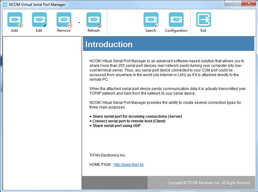
44 7. NCOM VIRTUAL SERIAL PORT MANAGER AND DRIVER INSTALLATION 7.1 NCOM Virtual Serial Port Manager Note: The virtual serial port driver is bundled with NCOM Virtual Serial Port Manager and is automatically installed when you install NCOM Virtual Serial Port Manager! The NCOM Virtual Serial Port Manager is an advanced software-based solution that allows you to communicate with serial device servers over networks easily. Thus, any serial device connected to your NCOM serial device server could be accessed from anywhere in the world (via internet or LAN) as if it were attached directly to the remote PC. When the attached serial port device sends communication data it is actually transmitted over TCP/IP network and back from the network to your serial device. NCOM Virtual Serial Port Manager has options to configure NCOM-413 with the options Add (add virtual serial port), Edit (edit virtual serial port parameters), Remove (remove virtual serial port), Refresh (refresh virtual serial port), Search (search all attached NCOM devices), Configuration (configure virtual serial port parameters) and Exit (exit NCOM Virtual Serial Port Manager). 43


45 7.2 Installing NCOM Virtual Serial Port Manager 1. Insert the software CD into your CD-ROM or DVD-ROM drive. 2. Open files in the CD and double click NCOM_setup to install NCOM Virtual Serial Port Manager. 3. When the confirmation for User Account Control appears, click Yes and the Setup - NCOM Virtual Serial Port Manager message appears. Click Next to proceed with the installation of NCOM Virtual Serial Port Manager 44


46 4. After you click Next, you will see following information. Click on Next and the Ready to Install message appears. Click Install to install NCOM Virtual Serial Port Manager. 5. After you click Install to install NCOM Virtual Serial Port Manager and virtual serial port driver for NCOM devices, you will see the following information. 45


47 6. When the message Completing the NCOM Virtual Serial Port Manager Setup Wizard appears, click Finish to finish the installation and exit setup program. 7. Double click the shortcut icon of NCOM Virtual Serial Port Manager on the desktop to launch NCOM Virtual Serial Port Manager. 8. You will see the main window of NCOM Virtual Serial Port Manager. 46
48 47
49 8. RUNNING NCOM VIRTUAL SERIAL PORT MANAGER After installing NCOM-413 hardware and NCOM Virtual Serial Port Manager, double click the shortcut icon of NCOM Virtual Serial Port Manager on the Desktop to start NCOM Virtual Serial Port Manager. 48
50 8.1 NCOM Virtual Serial Port Manager Functions NCOM Virtual Serial Port Manager has options to configure NCOM-413 with the options Add (add virtual serial port), Edit (edit virtual serial port parameters), Remove (remove virtual serial port), Refresh (refresh virtual serial port), Search (search all attached NCOM devices), Configuration (configure virtual serial port parameters) and Exit (exit NCOM Virtual Serial Port Manager). 49
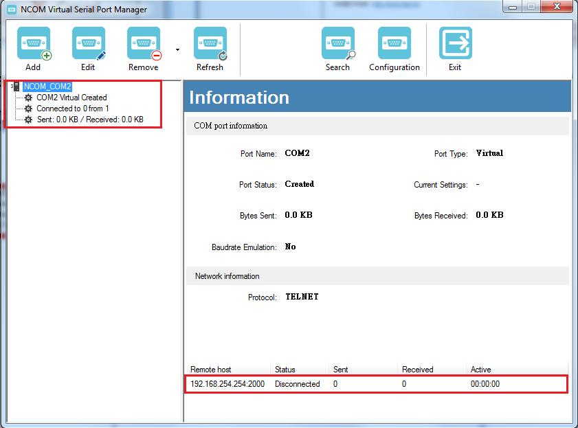
51 8.2 Manually Add Virtual Serial Port for NCOM Devices After opening NCOM Virtual Serial Port Manager, click Add to open the Add connection window. Under Add connection, select an available COM port (e.g. COM2. Note that NCOM Virtual Serial Port Manager will show your next available COM port) and type your NCOM device s IP address and port in IP Address and Remote Port respectively (e.g. IP Address: Port: 2000). After setting the COM port, IP address and remote port, click OK to add a new virtual serial port. After adding a new virtual serial port for NCOM devices, you will find information about the virtual serial port in the main window of NCOM Virtual Serial Port Manager. 50
52 51


53 8.3 Manually Edit Existing Virtual Serial COM Ports for NCOM Devices To edit existing virtual serial COM port for NCOM devices, select the existing virtual serial COM port and click Edit to open the Add connection window. Under Add connection, you can change the COM port number with the COM Port option (e.g. changing from COM2 to COM3) or change the IP address and remote port with the IP Address and Remote Port options respectively. After you change the settings, click OK to confirm the changes of the virtual serial port for NCOM devices. 52

54 8.4 Manually Remove Existing Virtual Serial COM Ports for NCOM Devices To remove an existing virtual serial port for NCOM devices, select an existing virtual serial port and click Remove. After clicking Remove, a confirmation message will appear asking Are you sure you want to delete NCOM_xxxxxxxx_COMx connection?. Confirm by clicking on Yes. 53

55 8.5 Refreshing Virtual Serial Port Information The virtual serial port information on the main window of NCOM Virtual Serial Port Manager may be incorrect or absent in some cases. In case this happens, you can click Refresh to recover the virtual serial port information. 54

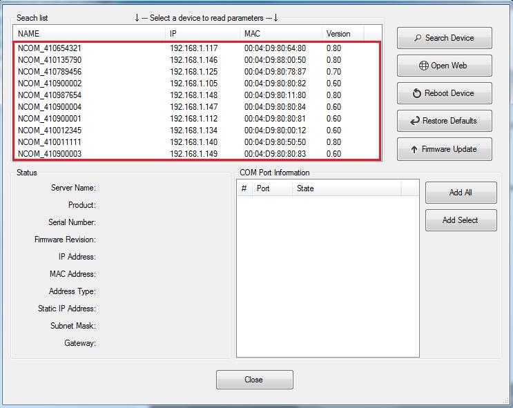
56 8.6 Automatically Search for NCOM Devices NCOM Virtual Serial Port Manager provides a search function, which can search all attached NCOM devices and can also automatically install virtual serial port driver for NCOM devices. You may also open the web console interface to configure NCOM, reboot NCOM devices, restore factory defaults and execute firmware update from here. Search (search all attached NCOM devices automatically). Clicking on Search takes you to the control menu page shown below: After a few seconds the NCOM Virtual Serial Port Manager will search and display all attached NCOM devices automatically. 55
57 56

58 8.6.1 Selecting an NCOM Device to Read Parameters After you select an attached NCOM device to configure the virtual serial port parameters, you will find the NCOM device information on the main window of NCOM Virtual Serial Port Manager. The information includes Server Name, Product, Serial Number, Firmware Revision, IP Address, MAC Address, Address Type, Static IP Address, Subnet Mask and Gateway. 57

59 8.6.2 Installing Virtual Serial Port Driver for NCOM Devices The search function can also create virtual COM ports and install virtual serial port drivers automatically. After selecting an attached NCOM device from the control menu click Add All button to install virtual serial port drivers automatically. After installation you will find four Create NCOM_XXXXXXXXX_COMX messages and the virtual serial ports created for the attached NCOM device. Click OK to finish creating virtual serial ports for your NCOM device. 58

60 In the Search window, there are five control buttons: Search Device, Open Web, Reboot Device, Restore Defaults and Firmware Update. 59

61 8.6.3 Manually Search for NCOM Devices The Search Device button searches for all attached NCOM device. If a new NCOM device is attached to the network system, you can click Search Device to find new NCOM devices. 60

62 8.6.4 Opening the Web Console Interface The Open Web button can be used to open the web console interface to configure NCOM. After selecting an attached NCOM device, click Open Web to open web console interface for that particular NCOM device. 61

63 8.6.5 Rebooting NCOM Devices The Reboot Device button reboots/resets your NCOM device. After selecting an attached NCOM device, click Reboot Device and a message will ask Are you sure you want to reboot device?. Click Yes to reboot/reset your NCOM device. 62

64 8.6.6 Restoring to Factory Defaults The Restore Defaults button restores the firmware to factory defaults. When you select an attached NCOM device, you can restore all options to factory default states by clicking the Restore Defaults button; After clicking Restore Defaults, a message will ask Are you sure you want to restore device to default?. Confirm by clicking Yes and the NCOM device will restore all options to factory defaults. 63
65 8.6.7 Firmware Update Tool The Firmware Update button opens the firmware update tool to upgrade NCOM- 413 firmware contents via Ethernet port. Before you click Firmware Update, please go to the web console interface of NCOM device firmware. Enable firmware update interface via Ethernet port in order to upgrade NCOM-413. Under the web console interface, select FIRMWARE UPDATE and click Update to enable the firmware update interface to upgrade to a new firmware. When you click Update, you will find the following message. The web console interface then waits for the firmware update tool program to launch in order to continue upgrading NCOM-413 s firmware. 64

66 After enabling the firmware update interface, please select this NCOM device then click the Firmware Update button. When you click Firmware Update, a message will ask Are you sure you want to update firmware?. Confirm by clicking Yes and the message Input new firmware file will appear. Use the File button to browse to the new firmware file and click on Update to start upgrading NCOM-413 s device firmware. 65
67 While upgrading, you will find the following message. After successfully upgrading the firmware contents, there will be a message stating Update Success!!. Click on OK to finish the firmware update procedure. 66
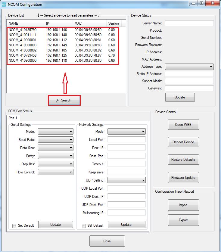
68 8.7 Configuring NCOM Devices NCOM Virtual Serial Port Manager has a configuration function which can configure all attached NCOM devices. It can also import/export configuration files for NCOM devices, open web console interface to configure NCOM device, reboot NCOM devices, restore factory defaults and execute firmware update. Configuration (configure all attached NCOM devices). Clicking on Configuration takes you to the control menu page shown below: 67

69 After a few seconds, NCOM Virtual Serial Port Manager will search all attached NCOM devices automatically, and you will find a device list information for all NCOM devices. 68

70 8.7.1 Selecting an NCOM Device to Configure Parameters When you select an attached NCOM device to configure the virtual serial port parameters, you will find Device Status, COM Port Status, Device Control and Configuration Import/Export on the main window of NCOM Configuration. 69


71 8.7.2 Device Status The Device Status section indicates the following information: Server Name, Product, Serial Number, Firmware Revision, IP Address, MAC Address, Address Type, Static IP Address, Subnet Mask and Gateway. In Device Status, you can modify Server Name, Address Type, Static IP Address, Subnet Mask and Gateway depending on your application. To change the serial device server name, modify the Server Name under Device Status. You need to enter a new name (such as NCOM-413) and click Update to set your serial device server to a new name. After clicking Update a confirmation message will ask Are you sure you want to change server name?. Confirm by clicking Yes. 70
72 After NCOM-413 successfully changes to a new name, a message will indicate Success!!. Click on OK to finish the procedure. NCOM-413 serial device server is configured with a default private IP address (static IP address): Many networks work in a DHCP network, which assigns IP addresses for client computers and NCOM-413 automatically. In this case, you need to set NCOM-413 s IP address to DHCP/AutoIP mode. Under Device Status of NCOM Configuration, select USE DHCP/AutoIP under Address Type: and click Update. A message will ask Are you sure you want to change Static IP to DHCP/AUTOIP?, confirm by clicking Yes and NCOM-413 will be set to DHCP/AutoIP mode. 71

73 After successfully setting NCOM-413 to DHCP/AutoIP mode, a message will indicate Success!!. Click on OK to finish changing the IP address type. When NCOM-413 is working in a static network environment, you need to set NCOM- 413 to a fixed IP address mode. Under Device Status of NCOM Configuration, select USE Static IP under Address Type: and enter a new static IP address (such as ), subnet mask (such as ) and gateway (such as ). Afterwards, click Update to set NCOM to a new static IP address for static network environments. After clicking Update, a confirmation message saying Are you sure you want to change new Static IP? will appear. Confirm by clicking Yes and NCOM-413 will be set to a new static IP address. 72

74 8.7.3 COM Port Status The COM Port Status section indicate the following information: PortX, Serial Settings and Network Settings. 73

75 Changing Serial Parameters To change serial parameters under Serial Settings for a virtual serial port, click Port1, Port2, Port3 or Port4 under COM Port Status. You can modify the following serial parameters: Serial Parameter Setting Default Values Mode RS-232, RS-422, RS-485 4W, RS-485-2W RS-232 Baud Rate 300bps to bps bps Data Size 5, 6, 7, 8 bits/character 8 bits/character Parity Check None, Odd, Even, Mark, Space None Stop Bits 1, 2, 1.5 bit(s) 1 bit Flow Control None or Hardware None Note: The default mode for NCOM-412 is RS-422. After changing the serial parameters, click Update to activate the new serial parameters. When the serial parameters are changed successfully, a message will indicate Update Success!!. 74

76 Click on OK to finish changing the serial parameters. If you want to save these serial parameters as defaults, you need to check Set Default and click on Update. When the new serial parameters are saved, a message will indicate Update Success!!. Click on OK to finish modifying serial parameters and saving new serial parameters. 75

77 Changing Network Operation Mode To change the network operation mode of a virtual serial port, click Port1 under COM Port Status. Under Network Settings, you may choose Driver Mode, RFC Server, RFC Client, TCP Raw - Server, TCP Raw - Client, Pair Connection Master Mode, Pair Connection Slave Mode and UDP depending on your application. After selecting an operation mode, click Update to set your NCOM-413 into the proper operation mode. After clicking Update to set your NCOM-413 s operation mode, a message will indicate Update Success!!. Click on OK to finish change operation mode procedure. 76

78 If you want to save the new operation mode as defaults, you need to check on Set Default and click on Update. When the new operation mode is saved, a message will indicate Update Success!!. Click on OK to finish changing and saving a new operation mode. To modify the network settings for a chosen operation mode please refer to Chapter 5 for detailed information. You can also modify the network parameter settings for your NCOM-413 serial device server. 77
79 Following are the default values of network parameters: Network Parameters Default Values Mode Driver Mode Timeout 0 seconds Keep alive time 10 minutes Address Type Static IP Static IP address Subnet Mask

80 8.7.4 Device Control The Device Control section contains the Search Device, Open Web, Reboot Device, Restore Defaults and Firmware Update functions. 79

81 Manually Search for NCOM Devices The Search button searches for all attached NCOM devices. If a new NCOM device is attached to the network system, you can click Search Device to find new NCOM devices. 80
82 81

83 Opening the Web Console Interface The Open Web button can be used to open the web console interface to configure NCOM. After selecting an attached NCOM device, click Open Web to open web console interface for that particular NCOM device. 82

84 Rebooting NCOM Devices The Reboot Device button reboots/resets your NCOM device when you need to. After selecting an attached NCOM device, click Reboot Device and a message will ask Are you sure you want to reboot device?. Click Yes to reboot/reset your NCOM device. 83

85 Restoring to Factory Defaults The Restore Defaults button restores the firmware to factory defaults. When you select an attached NCOM device, you can restore all options to factory default states by clicking the Restore Defaults button; After clicking Restore Defaults, a message will ask Are you sure you want to restore device to default?. Confirm by clicking Yes and the NCOM device will restore all options to factory defaults. After the NCOM device restores all options to factory default states, a message will indicate Please refresh device list to read updated parameters!. Click on OK to finish restoring device to factory defaults. 84


86 Firmware Update Tool The Firmware Update button opens the firmware update tool to upgrade NCOM- 413 firmware contents via Ethernet port. Before you click Firmware Update, please go to the web console interface of NCOM device firmware. Enable firmware update interface via Ethernet port in order to upgrade NCOM-413. Under the web console interface, select FIRMWARE UPDATE and click Update to enable the firmware update interface to upgrade to a new firmware. When you click Update, you will find the following message. The web console interface then waits for the firmware update tool program to launch in order to continue upgrading NCOM-413 s firmware. After enabling the firmware update interface, please select this NCOM device then click the Firmware Update button. 85

87 When you click Firmware Update, a message will ask Are you sure you want to update firmware?. Confirm by clicking Yes and the message Input new firmware file will appear. Use the File button to browse to the new firmware file and click on Update to start upgrading NCOM-413 s device firmware. 86
88 While upgrading, you will find the following message. After successfully upgrading the firmware contents, there will be a message stating Update Success!!. Click on OK to finish the firmware update procedure. 87

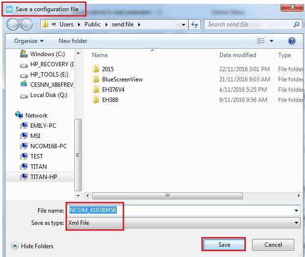
89 8.7.5 Importing/Exporting Configuration Settings The Configuration Import/Export function allows you to back up and recover your NCOM device configuration settings Exporting Configuration Settings Select an attached NCOM device then click the Export button. After you click Export you will find a Save a configuration file page. Click on Save to store the NCOM device configuration data to a NCOM_XXXXXXXXX.xml file. 88
90 89

91 Importing Configuration Settings Select an attached NCOM device then click the Import button. After you click Import you will find an Open page, select a NCOM configuration file and click Open to start uploading configuration data into NCOM. 90


92 After all configuration data is uploaded into NCOM device, a message will indicate Import Success!!. Click on OK to finish importing configuration data. 91

93 9. NCOM VIRTUAL SERIAL PORT MANAGER AND DRIVER UNINSTALLATION Uninstalling NCOM Virtual Serial Port Manager and Virtual COM Port Driver To uninstall NCOM Virtual Serial Port Manager and virtual serial port driver, click the "Start" button and navigate to Control Panel. Choose "Uninstall a program" under Programs. After you click Uninstall a program, a page with a list of all your installed programs will be shown. Select NCOM Virtual Serial Port Manager and click on Uninstall to uninstall NCOM Virtual Serial Port Manager and virtual serial port driver. 92


94 When you click on Uninstall, a message will ask Are you sure you want to completely remove NCOM Virtual Serial Port Manager and all of its components?. Confirm by click Yes. When uninstalling NCOM Virtual Serial Manager Port and virtual serial port driver in, you will find the following message. After successfully removing NCOM Virtual Serial Port Manager and virtual serial port driver, a message stating that NCOM Virtual Serial Port Manager was successfully removed from your computer will be shown. Click on OK to finish removing NCOM Virtual Serial Port Manager and virtual serial port driver. 93
NCOM SERIAL DEVICE SERVER 1XX SERIES USER S MANUAL
 NCOM SERIAL DEVICE SERVER 1XX SERIES USER S MANUAL 2017-07-07 Edition Titan Electronics Inc. Web: www.titan.tw Contents 1. INTRODUCTION... 4 1.1 Key Features... 5 1.2 Specifications... 6 2. PANEL LAYOUT
USB SERIAL OVER IP ADAPTER AnyplaceUSB-xCOM USER S MANUAL
 USB SERIAL OVER IP ADAPTER AnyplaceUSB-xCOM USER S MANUAL 2018 August Edition Titan Electronics Inc. Sharing Serial Ports over Ethernet and the Internet www.titan.tw The computer programs provided with
PCIe-400 USER S MANUAL
 PCIe-400 USER S MANUAL 2017 May Edition Titan Electronics Inc. Web: www.titan.tw The computer programs provided with the hardware are supplied under a license. The software provided should be used only
Industrial Serial Device Server
 1. Quick Start Guide This quick start guide describes how to install and use the Industrial Serial Device Server. Capable of operating at temperature extremes of -10 C to +60 C, this is the Serial Device
Lantech LSC-1102B SERIAL TO TCPIP CONVERTER. User Manual
 Lantech LSC-1102B SERIAL TO TCPIP CONVERTER User Manual V1.0 Sep 2016 Table of Contents 1. Introduction 3 Overview 4 Product Specifications 8 2. Description & Installation 10 Product Panel Views 10 LED
SERIAL TO ETHERNET CONVERTER E-P User Manual
 SERIAL TO ETHERNET CONVERTER E-P132-100 User Manual 1 Table of Contents Introduction... 4 Overview.. 5 Package Checklist 6 Block Diagram 7 Product Features...8 Product Specifications 9 Converter Description
Ethernet Serial Server
 Ethernet Serial Server Users Manual Eport-101, Eport-102, Eport-104, Eport108 1 INTRODUCTION... 1 1.1 FEATURES... 1 1.2 PRODUCT SPECIFICATIONS... 2 1.3 DEFAULT SETTINGS... 3 2 COMMUNICATION MODES... 4
Operation Manual of EX9132CST-Series
 Operation of EX9132CST-Series Serial to TCP/IP Converter (EX9132CST-2/ EX9132CST-RS485/ EX9132C-RS232) Version 1.0.0. 30.03.2017 Table of Contents 1 Introduction... 4 2 Overview... 5 2. 1 Package Checklist...
User Manual A08. User Manual
 A08 TABLE OF CONTENTS TABLE OF CONTENTS... 1 1. INTRODUCTION... 2 1.1. Key Features... 3 1.2. OS Requirement... 4 1.3. Specification... 4 1.4. Packing List... 4 2. OVERVIEW... 5 2.1. LED Definition...
1 port RS-232 Device Server
 1 port RS-232 Device Server Ethernet RJ45 1 Port Transmit and receive and Ethernet Link and 100/10M LED drive. 10/100 Mbps, auto MDI/MDIX Gateway IP address Serial Interface 1 Port 15 KV ESD protection
TCP/IP Converter. EX-9132 Operation Manual for 8051 Series
 TCP/IP Converter EX-9132 Operation Manual for 8051 Series First Edition, March 2005 Table of Contents 1. Introduction 3 Overview 4 Package Checklist 5 Block Diagram 6 Features 7 Product Specifications
TRP-C37. Ethernet to RS232/422/485 Converter. User s Manual. Printed Apr.2014 Rev 1.3
 TRP-C37 Ethernet to RS232/422/485 Converter User s Manual Printed Apr.2014 Rev 1.3 Trycom Technology Co.,Ltd No.35, Zhongxing Rd., Guishan Township, Taoyuan County 333, Taiwan. Tel : 886-3-350-3351 Fax:
MGate TM EIP3000 DF1 to EtherNet/IP Gateway User s Manual
 MGate TM EIP3000 DF1 to EtherNet/IP Gateway User s Manual First Edition, June 2009 www.moxa.com/product 2009 Moxa Inc. All rights reserved. Reproduction without permission is prohibited. MGate EIP3000
USER S MANUAL. PH232Ex1. #1 RS-232 Serial Port to Ethernet, Terminal Server/Client. Doc No: PH232Ex1-UM-001 IPEX. (IP Electronix)
") USER S MANUAL PH232Ex1 Doc No: PH232Ex1-UM-001 #1 RS-232 Serial Port to Ethernet, Terminal Server/Client IPEX (IP Electronix) Contents 1. INTRODUCTION... 3 2. SPECIFICATIONS... 3 3. PACKAGE CHECKLIST...
USER S MANUAL PH232Ex1 Doc No: PH232Ex1-UM-001 #1 RS-232 Serial Port to Ethernet, Terminal Server/Client IPEX (IP Electronix) Contents 1. INTRODUCTION... 3 2. SPECIFICATIONS... 3 3. PACKAGE CHECKLIST...
HOME AUTOMATION, INC. Model 93A00-1. Serial Server. User s Manual
 HOME AUTOMATION, INC. Model 93A00-1 Serial Server User s Manual Document Number 93I00-1 Rev. A December, 2009 Introduction The 93A00-1 is a RS232/RS485 to TCP/IP converter integrated with a robust system
Document Name: User Manual for SC10EK4 Serial to Ethernet Converter with 4 TCP Sockets. Index
 Document Name: User Manual for SC10EK4 Serial to Ethernet Converter with 4 TCP Sockets. Index Technical Specifications 1 Installation Procedure 1 LED Indications 2 Configuration Procedure Configuration
MGate MB3000 Modbus Gateway User Manual
 MGate MB3000 Modbus Gateway User Manual Sixth Edition, July 2012 www.moxa.com/product 2012 Moxa Inc. All rights reserved. MGate MB3000 Modbus Gateway User s Manual The software described in this manual
Operation Manual of EX-9132C-2. Serial to TCP/IP Converter
 Operation Manual of EX-9132C-2 Serial to TCP/IP Converter Version 1.1.0, 25th Jan. 2010 Table of Contents 1. Introduction 3 Overview 4 Package Checklist 4 Block Diagram 5 Features 6 Product Specifications
Serial to Ethernet Converter
 Serial to Ethernet Converter User s Manual Version 1.1 2004 Infosystem Technology Corporation Disclaimers The information in this manual has been carefully checked and is believed to be accurate. Infosystem
TRP-C37 User s Manual
 TRP-C37 User s Manual Ethernet to RS232/422/485 Converter Printed Oct. 2010 Rev 1.0 Trycom Technology Co., Ltd 1F, No.2-11, Sihu street, Yingge Township, Taipei, Taiwan ROC Tel: 886-2-86781191, Fax: 886-2-86781172
MGate MB3000 Modbus Gateway User s Manual
 User s Manual Seventh Edition, May 2013 www.moxa.com/product 2013 Moxa Inc. All rights reserved. User s Manual The software described in this manual is furnished under a license agreement and may be used
USB to RS-232/RS422/485. US-101-I USB To Serial Operation Manual
 USB to RS-232/RS422/485 US-101-I USB To Serial Operation Manual First Edition, Jun 2008 Table of Contents 1. Introduction 2 2. Package checklist 3 3. Product Specification 4 4. Product Panel Views Description
NordField Electronics
 NordField Electronics XS1000 TCP/IP to RS232/422/485 Device Server Overview and quick info sheet 3.0. Hardware Installation & Initial Setup 3.1 RS-232 Configuration:(DB9 Male) (DB9Male) Signal I/O PIN2
Tel: Fax:
 NP302 Series 2-port RS-232 232/485/422 to Ethernet Serial Server User manual Shenzhen 3onedata Technology Co.,Ltd Tel: +86-755-26702688 Fax: +86-755-26703485 www.3onedata.com Contents 1. Introduction...
e-net TCP/IP Converters
 e-net TCP/IP Converters E-P132 Operation Manual for 8051 Series First Edition, March 2005 Table of Contents 1. Introduction 3 Overview 4 Package Checklist 4 Block Diagram 5 Features 6 Product Specifications
RS-232/422/485 to Copper or Fiber. Ethernet Converter. User s Manual
 RS-232/422/485 to Copper or Fiber Ethernet Converter User s Manual Table Of Contents TABLE OF CONTENTS... 1 INTRODUCTION... 3 PRODUCT OVERVIEW... 3 PRODUCT FEATURES... 3 PACKING LIST... 4 LED INDICATORS...
LM300 Manager User Manual. Document Version: 1.1 LM300 Firmware Version: Bluetooth Firmware Version:
 LM300 Manager User Manual Document Version: 1.1 LM300 Firmware Version: 2.0.1 Bluetooth Firmware Version: 7.5.4279 LM300 Bluetooth Ethernet Access Point LM300 Manager User Manual i Revision Date Description
EX-6014WI RS232 to WiFi Wireless Adapter, w/ Mounting Kit
 EX-6014WI RS232 to WiFi Wireless Adapter, w/ Mounting Kit Thank you for purchasing this RS232 to WiFi Wireless Adapter (hereinafter referred to as WiFi-Adapter ), it is designed to communicate with RS232
SER-4485-SI-M USER S MANUAL
 SER-4485-SI-M USER S MANUAL 2017 May Edition Titan Electronics Inc. Web: www.titan.tw The computer programs provided with the hardware are supplied under a license. The software provided should be used
RS-232/422/485 Over IP Adapter
 RS-232/422/485 Over IP Adapter 1 port RS-232/422/485 Over IP Adapter NETRS2321E Actual product may vary from photo FCC Compliance Statement This equipment has been tested and found to comply with the limits
RS232/RS485/RS422 to TCP/IP Converter ITEM NO.: RS007
 RS232/RS485/RS422 to TCP/IP Converter ITEM NO.: RS007 RS007 is a universal data converter which support serial RS232, RS422 and RS485 to the TCP / IP intelligent communication converter, it offers RS485/RS422
CHIYU. Product Specification BF-450(M)/BF-430. RS232/RS485/RS422 To TCP/IP Converter Module. Release 1.0
/BF-430. RS232/RS485/RS422 To TCP/IP Converter Module. Release 1.0") CHIYU Product Specification BF-450(M)/BF-430 RS232/RS485/RS422 To TCP/IP Converter Module Release 1.0 Date: October 13, 2003 Author: Eric Chang Table of Content 1. Revision History--------------------------------------------------3
CHIYU Product Specification BF-450(M)/BF-430 RS232/RS485/RS422 To TCP/IP Converter Module Release 1.0 Date: October 13, 2003 Author: Eric Chang Table of Content 1. Revision History--------------------------------------------------3
WM-120. Serial to Ethernet Module. Serial to Ethernet Module. User Manual. Version 1.0. Infosystem Technology Corporation, Ltd.
 W M - 1 2 0 User Manual Version 1.0 Infosystem Technology Corporation, Ltd. Index 1. Disclaimers... 1. A. Warranty... 2. B. Trademark... 2. 2. Product Information... 3. A. Introduction... 3. B. Features...
LM300 Bluetooth Ethernet Access Point/Server 3 Simultaneous Bluetooth SPP Connections
 TECHNOLOGIES Bluetooth Ethernet Access Point/Server 3 Simultaneous Bluetooth SPP Connections Android XP Vista Part No Bluetooth Features Supports 3 simultaneous Bluetooth SPP Connections CSR Bluecore 04
TRP-C37. Ethernet to RS232/422/485 Converter. User s Manual. Printed September Rev 1.6
 TRP-C37 Ethernet to RS232/422/485 Converter User s Manual Printed September 1 2015 Rev 1.6 Trycom Technology Co.,Ltd No.35, Zhongxing Rd., Guishan Township, Taoyuan County 333, Taiwan. Tel : 886-3-350-3351
PCI Express 16-Port Serial I/O Cards
 PCI Express 16-Port Serial I/O Cards The PCIe-1600 PCI Express 16-port serial I/O card is a plug & play high-speed serial I/O expansion card for PCI Express bus. Connecting to a PCI Express bus on your
SERIAL TO WiFi CONVERTER EX-9486C-W User Manual
 SERIAL TO WiFi CONVERTER EX-9486C-W User Manual Table of Contents Introduction 3 Overview. 4 Package Check List.. 5 Product Features.. 6 Hardware Specifications. 8 Converter Description.. 11 Product Panel
Operation Manual EX-9133C-2-MTCP
 Operation Manual EX-9133C-2-MTCP Modbus TCP to Modbus RTU/ASCII Converter Version 1.0.1 20th Oct. 2016 Page 0 Table of Contents 1. Introduction 3 Overview 4 Package Checklist 4 Block Diagram 5 Features
TRP-C34H. Ethernet to 4 RS232/422/485 Converter. User s Manual. Printed Sep Rev 1.1
 TRP-C34H Ethernet to 4 RS232/422/485 Converter User s Manual Printed Sep. 2013 Rev 1.1 Trycom Technology Co., Ltd 1F, No.2-11, Sihu street, Yingge Township, Taipei, Taiwan ROC Tel: 886-2-86781191, Fax:
This 4-port RS-422/485 Adapter is provided with an external switching power adapter in the package.
 USB-4COMi-M USB to Quad RS-422/485 to Serial Adapter Manual The USB to Industrial Quad RS-422/485 Adapter is designed to make industrial communication port expansion quick and simple. Connecting to a USB
BF-430 User Manual Document Version 1.0 Web Version realcom Firmware Version ,Apr
 BF-430 User Manual Document Version 1.0 Web Version realcom 2009-02-07 Firmware Version 1.13.00,Apr 4 2011 Index Ⅰ Hardware Introduction...1 Ⅱ Product Overview...3 Ⅲ WEB Login...4 Ⅳ Web Instruction...10
NET101. RS232 / RS422 / RS485 to Ethernet Converter. User s Manual. Version 1.2
 NET101 RS232 / RS422 / RS485 to Ethernet Converter User s Manual Version 1.2 Copyright Information Copyright 2004-2005, Mega System Technologies, Inc. All rights reserved. Reproduction without permission
5600 Series. 8 and 16-port Serial Device Servers. Features. Internet Readiness for up to 16 Serial Devices
 5600 Series 8 and 16-port Features Up to 16 ports supporting RS-22, RS-422, or RS-485 operation Compact desktop model or standard 19-inch rackmount model Auto-detecting 10/100 Mbps Ethernet 15 KV ESD surge
UPort 2000 Series User s Manual
 User s Manual Second Edition, December 2012 www.moxa.com/product 2012 Moxa Inc. All rights reserved. User s Manual The software described in this manual is furnished under a license agreement and may be
USB-2COM-BB USER S MANUAL
 USB-2COM-BB USER S MANUAL 2017 May Edition Titan Electronics Inc. Web: www.titan.tw The computer programs provided with the hardware are supplied under a license. The software provided should be used only
INDEX. Document Name : User Manual for SC10EJ Serial to Ethernet Converter
 Document Name : User Manual for SC10EJ Serial to Ethernet Converter Page 1 of 10 INDEX 1. Technical Specifications 1 2. Modes of Operation 1 3. Configuring the SC10 EJ : Through Serial Port 2 a. Configuring
Serial Device Server- Dual Port Quick Installation Guide
 Serial Device Server- Dual Port Quick Installation Guide Introducing the Serial Device Server The Serial Device Server-Dual Port allows to connect a serial device to a Local Area Network (LAN) or Wide
Model XS1000 TCP/IP to RS232/422/485 Device Server User s Manual
 Model XS1000 TCP/IP to RS232/422/485 Device Server User s Manual 3.0. Hardware Installation & Initial Setup 3.1 RS-232 Configuration:(DB9 Male) (DB9Male) Signal I/O PIN2 RXD IN PIN3 TXD OUT PIN5 GND -
NetCom Mini. SCADA system Building automation system Self-service banking system Other remote and distributed serial devices control
 Features Can control 1 x RS232 device located virtually anywhere (via Ethernet or Internet) LAN interface 10BaseT/100BaseTx Ethernet Configuration utility automatically finds NetCom Mini devices in the
Matrix-710. Linux-Ready Cortex-A5 Industry IoT Gateway. Hardware Guide. Version: Nov.
 Matrix-710 Linux-Ready Cortex-A5 Industry IoT Gateway Hardware Guide Version: 1.01 2017 Nov. Copyright Artila Electronics Co., Ltd. All Rights Reserved Trademarks The Artila logo is a registered trademark
PCI Express 4-Port Industrial Serial I/O Cards
 PCI Express 4-Port Industrial Serial I/O Cards The PCIe-400i and PCIe-400i-SI PCI Express 4-port industrial serial I/O cards are plug & play high-speed serial I/O expansion cards for the PCI Express bus.
Infosystem. User Manual. Version 1.0. Serial to Ethernet Converter with 3 sockets. Infosystem Technology Corporation, Ltd.
 WS-100B Serial to Ethernet Converter with 3 sockets Copyright 2005 Infosystem Technology Corporation, Ltd. No. 45, Lane 167, Dongnan St. Hsinchu, Taiwan 300, R.O.C. TEL: +886-3-562-7187 FAX: +886-3-561-1435
Document Name: User Manual for SC10MK, Modbus RTU to Modbus TCP Converter
 Document Name: User Manual for SC10MK, Modbus RTU to Modbus TCP Converter Login for the first time, please use http://192.168.1.100 To key in user name and password is for identifying authorization. Default
Real/Virtual COM. JetPort Commander
 INDUSTRIAL SERIAL DEVICE SERVER 1-port RS-232/422/485 Serial Device Server 5601 The 5601 is a RS-232/422/485 to Redundant Serial Device Server. The serial interface is configurable in software and supports
DT Desktop Series
 5600-8-DT Desktop Series Compact 8-port Serial s Features 8 ports supporting RS-232, RS-422, or RS-485 operation Compact desktop size Auto-detecting 10/ 100 Mbps Ethernet 15 KV ESD surge protection for
Industrial Device Server IDS-3010 Fiber Series
 USER S MANUAL Industrial Device Server IDS-3010 Fiber Series Ver. 1.0, Jan. 2008 Table of Content Getting to Know Your Device Server... 3 1.1 About the IDS-3010 Serial Device Server... 3 1.2 Software Features...
rbox610 Series Robust Din-rail Fanless Embedded System Web Configuration and App Software User s Manual
 rbox610 Series Robust Din-rail Fanless Embedded System Web Configuration and App Software User s Manual Disclaimers This manual has been carefully checked and believed to contain accurate information.
Product Manual. USB to Optical Adapter Industrial Isolated RS- 232/422/485. Coolgear, Inc. Version 2.1 December 2018 Model Number: USB-COMi-Si-M
 USB to Optical Adapter Industrial Isolated RS- 232/422/485 Product Manual Coolgear, Inc. Version 2.1 December 2018 Model Number: USB-COMi-Si-M 2 USB-COMi-SI-M Product Manual Revision History Revision Date
Communication adapter RS485/422 over the Ethernet ELO E222. User manual
 Communication adapter RS485/422 over the Ethernet ELO E222 User manual Table Of Content: 1.0 Introduction... 3 1.1 Application... 3 2.0 How does it works?... 4 3.0 Installation... 4 3.1 Ethernet connection...
USB OVER ETHERNET ANYPLACEUSB-H3 USER S MANUAL
 USB OVER ETHERNET ANYPLACEUSB-H3 USER S MANUAL 2018 August Edition TITAN Electronics Inc. Sharing USB Ports over Ethernet and the Internet www.titan.tw The computer programs provided with the hardware
Universal ipulse Ethernet Adapter. User Manual
 Universal ipulse Ethernet Adapter User Manual January 2011 Table of Contents Introduction 3 Overview 4 Package Checklist 4 Product Features 4 Product Specifications 6 IPulse-e Description & Installation
Introduction & Specifications of Hi-Speed USB to Industrial Dual Ports RS-422/485 Adapter
 Introduction & Specifications of Hi-Speed USB to Industrial Dual Ports RS-422/485 Adapter USB to Dual RS-422/485 Adapter (USB-2COMi-M) USB to Dual Opto-isolated RS-422/485 Adapter (USB-2COMi-SI-M) - with
Modbus TCP/RTU Gateway
 Modbus TCP/RTU Gateway Hardware Installation Guide for models IE-GW-MB-2TX-1RS232/485 IE-GWT-MB-2TX-1RS232/485 Second Edition, June 2014 1516600000/01/06.14 Important note: The detailed user manual, additional
USB to RS-232/RS422/485. URK-228-I USB To Serial Operation Manual
 USB to RS-232/RS422/485 URK-228-I USB To Serial Operation Manual First Edition, Feb 2012 Table of Contents 1. Introduction 2 2. Package checklist 3 3. Product Specification 4 4. Product Panel Views Description
Installation Guide of Hi-Speed USB to Octal RS-232/422/485 Adapter
 Installation Guide of Hi-Speed USB to Octal RS-232/422/485 Adapter Introduction The USB to Octal Serial Adapter is designed to make serial port expansion quick and simple. Connecting to a USB port on your
ECOV-110 User s Manual
 ECOV-110 User s Manual 1. Product Introduction 2. Windows Utility 3. Web Console 4. Command Mode 5. Connection Test Appendix A. ECOV-110 Firmware upgrade ECOV-110 1. ECOV-110 Product Introduction: 1.1.
DGH A3000 Configuration Guide For use with DGH Modules
 DGH A3000 Configuration Guide For use with DGH Modules Revision Date: 12/07/05 Version: 1.00 Contact Information: http://www.dghcorp.com Ph: (603) 622-0452 Fax: (603) 622-0487 Mailing Address: DGH Corporation
EX KVIS RS232/422/485 3-in-1 Serial to USB Adapter (w/ 4KV Isolation, 15KV ESD Surge Protection)
") EX-1331-4KVIS RS232/422/485 3-in-1 Serial to USB Adapter (w/ 4KV Isolation, 15KV ESD Surge Protection) 1. Introduction Thank you for purchasing this RS232/422/485 3-in-1 Serial to USB Adapter. It is an
EX-1331-4KVIS RS232/422/485 3-in-1 Serial to USB Adapter (w/ 4KV Isolation, 15KV ESD Surge Protection) 1. Introduction Thank you for purchasing this RS232/422/485 3-in-1 Serial to USB Adapter. It is an
8 Port USB to RS- 232/422/485 Octal Adapter. Product Manual. Coolgear, Inc. Version 1.1 April 2018 Model Number: USB-8COMi-RM.
 8 Port USB to RS- 232/422/485 Octal Adapter Product Manual Coolgear, Inc. Version 1.1 April 2018 Model Number: USB-8COMi-RM 2 USB-8COMi-RM Product Manual Revision History Revision Date Author Comments
TRP-C37M User s Manual
 TRP-C37M User s Manual MODBUS TCP to RTU/ASCII Gateway Printed OCT. 2010 Rev 1.0 Trycom Technology Co., Ltd 1F, No.2-11, Sihu street, Yingge Township, Taipei, Taiwan ROC Tel: 886-2-86781191, Fax: 886-2-86781172
Motortronics VirtualSCADA VS2-MT Communication Gateway VS2-MT User Manual Revision
 Motortronics VirtualSCADA VS2-MT Communication Gateway VS2-MT User Manual Revision 1.03.00 Motortronics / Phasetronics 1600 Sunshine Drive Clearwater, Florida 33765 Tel: 727-573-1819 Fax: 727-573-1803
3.1 I-7560 Pin Assignment and Specifications: Introduction
 3.1 I-7560 Pin Assignment and Specifications: Introduction The I-7560 adds a Windows serial Com port via its USB connection and is compatible with new & legacy RS-232 devices. USB Plug and Play allows
USB to RS-422/485 Serial Adapter
 USB to RS-422/485 Serial Adapter User Manual Ver. 4.00 All brand names and trademarks are properties of their respective owners. Contents: Chapter 1: Introduction... 3 1.1 Product Introduction... 3 1.2
IDS-141A/181A. Industrial 4-port/8-port slim type serial to Ethernet device server. Features. Introduction. DS-Tool
 4/8 Port v1.5 / Dec, 2011 Features 4-port/8-port slim type serial to Ethernet device server Operating Modes : Virtual Com, Tunnel, TCP Server, TCP Client, UDP Multiple host devices : 5 host devices: Virtual
LM300 Bluetooth Ethernet Access Point/ Server 3 simultaneous Bluetooth SPP connections
 Bluetooth Ethernet Access Point/ Server 3 simultaneous Bluetooth SPP connections Product: Features Server Features Supports 0/00 Mbps Ethernet Supports RS-3, RS-4 and RS-485 serial interface Supports LAN
ABLELink. Modbus Gateway MB5000 Series User s Manual
 ABLELink MB5000 Series User s Manual Version 1.1 Updated in March, 2010 TEL: 886-3-5508137 FAX: 886-3-5508131 http://www.atop.com.tw Table of Contents Table of Contents... 2 Introduction... 4 Features...
Support 1 RS-232 or RS-485/422 serial port to 1 10/100Base-T(X) self-adaptive Ethernet interface
 self-adaptive Ethernet interface") GW1101 Series Wall Mounting 1 RS-232 or RS-485/422 Modbus Gateway Support 1 RS-232 or RS-485/422 serial port to 1 10/100Base-T(X) self-adaptive Ethernet interface Support conversion between Modbus RTU/ASCII
GW1101 Series Wall Mounting 1 RS-232 or RS-485/422 Modbus Gateway Support 1 RS-232 or RS-485/422 serial port to 1 10/100Base-T(X) self-adaptive Ethernet interface Support conversion between Modbus RTU/ASCII
USB-COMi-TB USB to Industrial Single RS-422 / 485 Adapter Manual. Specifications and Features
 USB-COMi-TB USB to Industrial Single RS-422 / 485 Adapter Manual The USB-COMi-TB USB-to-Industrial Single RS-422/485 Adapter is designed to make industrial communication port expansion quick and simple.
EX & EX-45362IS 2S RS232/422/485 3-in-1 Serial PCIe Card
 EX-45362 & EX-45362IS 2S RS232/422/485 3-in-1 Serial PCIe Card Congratulation on your purchasing this high performance 2-Port RS232/422/485 3-in-1 Serial PCIe Host Adapter. The adapter is high speed PCIe
Product Manual. 2 Port USB to RS-422 /485 Optical Isolated Adapter. Coolgear, Inc. Version 1.1 March 2018 Model Number: USB-2COMi-Si-M
 2 Port USB to RS-422 /485 Optical Isolated Adapter Product Manual Coolgear, Inc. Version 1.1 March 2018 Model Number: USB-2COMi-Si-M 2 USB-2COMi-Si-M Product Manual Revision History Revision Date Author
Serial to TCP/IP Converter
 Operation Manual EX9133C-RS485/ PoE Serial to TCP/IP Converter Version 1.0.1 20th Oct. 2016 EX-9133C-RS485/PoE Manual Version 1.0 13.11.2015 Page 0 Table of Contents 1. Introduction 3 Overview 4 Package
ECAN-240. (Modbus TCP to 2-port CAN Bus Gateway User manual) ECAN-240 Modbus TCP to 2-port CAN Bus Gateway User Manual, Version 1.0.
 ECAN-240 Modbus TCP to 2-port CAN Bus Gateway User Manual, Version 1.0.") ECAN-240 (Modbus TCP to 2-port CAN Bus Gateway User manual) ECAN-240 Modbus TCP to 2-port CAN Bus Gateway User Manual, Version 1.0.0 Page: 1 Table of Contents Table of Contents -----------------------------------------------------------------------------2
ECAN-240 (Modbus TCP to 2-port CAN Bus Gateway User manual) ECAN-240 Modbus TCP to 2-port CAN Bus Gateway User Manual, Version 1.0.0 Page: 1 Table of Contents Table of Contents -----------------------------------------------------------------------------2
2-Port RS-232/422/485 Serial over IP Ethernet Device Server Installation Guide
 2-Port RS-232/422/485 Serial over IP Ethernet Device Server Installation Guide Introduction The 2-Port RS-232/422/485 Serial over IP Ethernet Device Server is designed to operate serial ports over 10/100
NE-4100 Series User s Manual
 Ninth Edition, June 2008 www.moxa.com/product 2008 Moxa Inc., all rights reserved. Reproduction without permission is prohibited. The software described in this manual is furnished under a license agreement
ecov-110 User s Manual (V0.9f_Eng)
") ecov-110 User s Manual (V0.9f_Eng) 1. Product Introduction 2. Windows Utility 3. Web Console 4. Command Mode 5. Connection Test Appendix A. ecov-110 Firmware Upgrade Appendix B. ecov-110 Serial Advanced
ecov-110 User s Manual (V0.9f_Eng) 1. Product Introduction 2. Windows Utility 3. Web Console 4. Command Mode 5. Connection Test Appendix A. ecov-110 Firmware Upgrade Appendix B. ecov-110 Serial Advanced
Embedded Modbus TCP Module GS11-MT. User Manual REV 1.1. SST Automation.
 Embedded Modbus TCP Module GS11-MT User Manual REV 1.1 SST Automation E-mail: SUPPORT@SSTCOMM.COM WWW.SSTCOMM.COM Catalog 1 About the Embedded Module... 4 1.1 General...4 1.2 Features... 4 1.3 Specifications...4
GPORT104 User s Manual
 GPORT104 User s Manual Beijing Golden Global View Co., Ltd. RAYON Technology Co., Ltd. Version( V 1.01) Contents I. Product Introduction II. Features III. Technical Specifications IV. Hardware Installation
SB72EX User's Manual
 etburner SB72EX User's Manual Revision: 1.8 October 8, 2009 SB72EX User's Manual, 350030-001 Table of Contents Table of Contents...2 Overview of the SB72EX Dual-port Serial to Ethernet Device... 3 Overview
RS-232 / RS-422 / RS-485 over Fast Ethernet Media Converter
 RS-232 / RS-422 / RS-485 over Fast Ethernet Media Converter Serial Interface One RS-232/422/485 port to one 100Base-FX Media Converter Cost-effective solution for RS-232 to Ethernet application Supports
TRP-C37M User s Manual
 TRP-C37M User s Manual MODBUS TCP to RTU/ASCII Gateway Printed May. 2011 Rev 1.1 Trycom Technology Co., Ltd 1F, No.2-11, Sihu street, Yingge Township, Taipei, Taiwan ROC Tel: 886-2-86781191, Fax: 886-2-86781172
USER S MANUAL. PH485Ex1. #1 RS-485 Serial Port to Ethernet, Terminal Server/Client. Doc No: PH485Ex1-UM-001 IPEX. (IP Electronix)
") USER S MANUAL PH485Ex1 Doc No: PH485Ex1-UM-001 #1 RS-485 Serial Port to Ethernet, Terminal Server/Client IPEX (IP Electronix) Contents 1. INTRODUCTION... 3 2. SPECIFICATIONS... 3 3. PACKAGE CHECKLIST...
USER S MANUAL PH485Ex1 Doc No: PH485Ex1-UM-001 #1 RS-485 Serial Port to Ethernet, Terminal Server/Client IPEX (IP Electronix) Contents 1. INTRODUCTION... 3 2. SPECIFICATIONS... 3 3. PACKAGE CHECKLIST...
SSE232-LE Serial Server- User s Manual
 www.exemys.com Rev.6 1 Products are in constant evolution to satisfy our customer needs. For that reason, the specifications and capabilities are subject to change without prior notice. Updated information
NetCom Plus 113. Contact Online. More Pictures. Click on the thumbnails for the large picture. Overview
 VS Vision Systems GmbH / Part Number 6645 Features Controls 1 RS232/422/485 device located virtually anywhere via Ethernet, WLAN or Internet Easy selection of RS232, RS422 or RS485 by single DIP switch
I-7560U/7561U/7563U. User Manual WARRANTY WARNING COPYRIGHT TRADEMARKS CONTACT US
 I-7560U/7561U/7563U User Manual USB tto RS--232//422//485 Converrtterrss Verr.. 1..0,, Decc.. 2013 WARRANTY All products manufactured by ICP DAS are warranted against defective materials for a period of
Communication adapter RS232 over the Wi-Fi ELO E231. User manual
 Communication adapter RS232 over the Wi-Fi ELO E231 User manual Table Of Content: 1.0 Introduction...3 1.1 Application...3 2.0 How does it works?...4 3.0 Installation...4 3.1 Wi-Fi connection...4 3.2 RS-232
NetCom Plus 413 POE. Contact Online. More Pictures. Click on the thumbnails for the large picture. Overview
 VS Vision Systems GmbH / Part Number 6676 NetCom Plus 413 POE Features Controls 4 RS232 or RS422/485 devices located virtually anywhere via Ethernet, WLAN or Internet Easy selection of RS232, RS422 or
NE-4100-P Series User s Manual
 First Edition, September 006 www.moxa.com/product MOXA Technologies Co., Ltd. Tel: +886--899-0 Fax: +886--899- Web: www.moxa.com MOXA Technical Support Worldwide: support@moxa.com The Americas support@usa.moxa.com
Ethernet to Serial Port Module RS-232/422/485 to Internet Gateway
 Ethernet to Serial Port Module RS-232/422/485 to Internet Gateway (Model: IPM-S) Wireless Gateway: Active RFID Gateway Bluetooth to Internet Application: Energy Meter Networks Motor Control Industrial
Introduction & Specifications of Hi-Speed USB to Serial Adapters
 Introduction & Specifications of Hi-Speed USB to Serial Adapters The USB Serial Adapters consist of the following models: USB Single Serial Adapter (ES-U-1001, ES-U-1001-A) USB Single Serial Adapter (ES-U-1001-M,
Features and Benefits. SNMP MIB-II for network management. Certifications
 NPort 5600-DT Series 8-port RS-232/422/485 serial device servers Features and Benefits 8 serial ports supporting RS-232/422/485 Compact desktop design 10/100M auto-sensing Ethernet Easy IP address configuration