UNIT-II 1. Discuss the issues in the data link layer. Answer:
|
|
|
- Nelson McGee
- 5 years ago
- Views:
Transcription
1 UNIT-II 1. Discuss the issues in the data link layer. Answer: Data Link Layer Design Issues: The data link layer has a number of specific functions it can carry out. These functions include 1. Providing a well-defined service interface to the network layer. 2. Dealing with transmission errors. 3. Regulating the flow of data so that slow receivers are not swamped by fast senders. To accomplish these goals, the data link layer takes the packets it gets from the network layer and encapsulates them into frames for transmission. Each frame contains a frame header, a payload field for holding the packet, and a frame trailer, as illustrated in Fig.1. Frame management forms the heart of what the data link layer does. In fact, in many networks, these functions are found only in the upper layers and not in the datalink layer. However, no matter where they are found, the principles are pretty much the same, so it does not really matter where we study them. In the data link layer they often show up in their simplest and purest forms, making this a good place to examine them. 2. Suppose we want to transmit the message and protect it from errors using the CRC polynomial x Use polynomial long division to determine the message that should be transmitted. Answer:
2 3. Discuss the principle of stop and wait flow control algorithm. Draw time line diagrams and explain how loss of a frame and loss of an ACK are handled. What is the effect of delay-bandwidth product on link utilization? Answer:
3
4
5 4. Assume that a frame consists of 6 characters encoded in 7-it ASCII. Attach a parity bit for every character to maintain even parity. Also attach a similar parity bit for each bit position across each of the bytes in the frame. Show that such a 2-dimensional parity scheme can detect all 1-bit, 2-bit and 3-bit errors and can correct a single bit error. 5. Explain the following Error Detection Mechanisms. (i) Cyclic Redundancy Check. (ii) Discuss briefly about link level flow control. 6. List the three main functions performed by the data link layer of the ISO OSI model. Answer : Data link layer is most reliable node to node delivery of data. It forms frames from the packets that are received from network layer and gives it to physical layer. It also synchronizes the information which is to be transmitted over the data. Error controlling is easily done. The encoded data are then passed to physical. Error detection bits are used by the data link layer. It also corrects the errors. Outgoing messages are assembled into frames. Then the system waits for the acknowledgements to be received after the transmission. It is reliable to send message. 1. Framing: Frames are the streams of bits received from the network layer into manageable data units. This division of stream of bits is done by Data Link Layer. 2. Physical Addressing: The Data Link layer adds a header to the frame in order to define physical address of the sender or receiver of the frame, if the frames are to be distributed to different systems on the network. 3. Flow Control: A flow control mechanism to avoid a fast transmitter from running a slow receiver by buffering the extra bit is provided by flow control. This prevents traffic jam at the receiver side. 4. Error Control: Error control is achieved by adding a trailer at the end of the frame. Duplication of frames are also prevented by using this mechanism. Data Link Layers adds mechanism to prevent duplication of frames. 5. Access Control: Protocols of this layer determine which of the devices has control over the link at any given time, when two or more devices are connected to the same link.
 code? Answer: Cyclic codes in Error Detection and Correction Cyclic codes are special linear block codes with one extra property.")
6 7. State which layers of the ISO OSI model does the following interconnecting devices operate. (1) Repeaters (2) Bridges (3) Routers (4) Gateways 8. What is cyclic code and explain Cyclic Redundancy Check (CRC) code? Answer: Cyclic codes in Error Detection and Correction Cyclic codes are special linear block codes with one extra property. In a cyclic code, if a code word is cyclically shifted (rotated), the result is another code word. For example, if is a code word and we cyclically left-shift, then is also a code word. In this case, if we call the bits in the first word a0 to a6 and the bits in the second word b0 to b6, we can shift the bits by using the following: b1=a0 b2=a1 b3=a2 b4=a3 b5=a4 b6=a5 b0=a6 Cyclic Redundancy Check: One of the categories of cyclic codes called the cyclic redundancy check (CRC) that is used in networks such as LANs and WANs. The following table shows an example of a CRC code which shows both the linear and cyclic properties of this code. In the encoder, the data word has k bits (4 here); the code word has n bits (7 here). The size of the data word is augmented by adding n - k (3 here) 0s to the right-hand side of the word. The n- bit result is fed into the generator. The generator uses a divisor of size n - k + I (4 here), predefined and agreed upon. The generator divides the augmented Data word by the divisor (modulo-2 division). The quotient of the
7 division is discarded; the remainder (r2r1r0) is appended to the data word to create the code word. The decoder receives the possibly corrupted code word. A copy of all n bits is fed to the checker which is a replica of the generator. The remainder produced by the checker is a syndrome of n - k (3 here) bits, which is fed to the decision logic analyzer. The analyzer has a simple function. If the syndrome bits are all 0s, the 4 leftmost bits of the code word are accepted as the data word (interpreted as no error); otherwise, the 4 bits are discarded (error). Encoder: The process of modulo-2 binary division is the same as the familiar division process for decimal numbers. In each step, a copy of the divisor is XORed with the 4 bits of the dividend. The result of the XOR operation (remainder) is 3 bits (in this case), which is used for the next step after 1 extra bit is pulled down to make it 4 bits long. There is one important point we need to remember in this type of division. If the leftmost bit of the dividend (or the part used in each step) is 0, the step cannot use the regular divisor; we need to use an all-0s divisor. When there are no bits left to pull down, we have a result. The 3-bit remainder forms the check bits (r2, r1 and r0). They are appended to the data word to create the code word.
8 Decoder: The code word can change during transmission. The decoder does the same division process as the encoder. The remainder of the division is the syndrome. If the syndrome is all 0s, there is no error; the data word is separated from the received code word and accepted. Otherwise, everything is discarded. Consider the following figure which shows two cases: The left hand figure shows the value of syndrome when no error has occurred; the syndrome is 000. The righthand part of the figure shows the case in which there is one single error. The syndrome is not all 0s (it is 011). For example, consider the following figure where the encoder takes the data word and augments it with n - k number of 0s. It then divides the augmented data word by the divisor. 9. What is meant by linear Block Code and explain Simple Parity-Check Code? Answer: Simple Parity Check Code Linear Block Codes: A linear block code is a code in which the exclusive OR (addition modulo-2) of two valid code words creates another valid code word. The scheme in the above table is a linear block code because the result of XORing any code word with any other code word is a valid code word. For example, the XORing of the second and third code words creates the fourth one. Minimum Distance for Linear Block Codes:
9 It is simple to find the minimum Hamming distance for a linear block code. The minimum Hamming distance is the number of 1s in the nonzero valid code word with the smallest number of 1s. In the above table the numbers of 1s in the nonzero code words are 2, 2, and 2. So the minimum Hamming distance is dmin =2. Simple Parity-Check Code: The simple parity-check code is the most familiar error-detecting code. In this code, a k-bit data word is changed to an n-bit code word where n = k + 1. The extra bit, called the parity bit, is selected to make the total number of 1s in the code word even. Although some implementations specify an odd number of 1s. The minimum Hamming distance for this category is dmin =2, which means that the code is a single-bit error-detecting code and it cannot correct any error. The following figure shows possible structure of an encoder (at the sender) and a decoder (at the receiver). The encoder uses a generator that takes a copy of a 4-bit data word (a0, a1, a2 and a3) and generates a parity bit r0. The data word bits and the parity bit create the 5-bit code word. The parity bit that is added makes the number of 1s in the code word even. This is normally done by adding the 4 bits of the data word (modulo-2). r0=a3+a2+a1+a0 (modulo-2) The result is the parity bit. In other words, If the number of 1s is even, the result is 0; if the number of 1s is odd, the result is 1.In both cases, the total number of 1s in the code word is even.
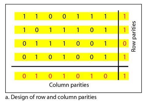
10 The sender sends the code word which may be corrupted during transmission. The receiver receives a 5-bit word. The checker at the receiver does the same thing as the generator in the sender with one exception: The addition is done over all 5 bits. s0=b3+b2+b1+b0+ q0 (modulo-2) The result, which is called the syndrome, is just 1 bit. The syndrome is 0 when the number of 1s in the received code word is even; otherwise, it is 1. The syndrome is passed to the decision logic analyzer. If the syndrome is 0, there is no error in the received code word, the data portion of the received code word is accepted as the data word, if the syndrome is 1, the data portion of the received code word is discarded. The data word is not created. For example, the sender sends the data word The code word created from this data word is 10111, which is sent to the receiver. We examine five cases: 1. No error occurs; the received code word is The syndrome is 0. The data word 1011 is created. 2. One single-bit error changes a1. The received code word is The syndrome is 1. No data word is created. 3. One single-bit error changes r0. The received code word is The syndrome is 1. No data word is created. Note that although none of the data word bits are corrupted, no data word is created because the code is not sophisticated enough to show the position of the corrupted bit. 4. An error changes r0 and a second error changes a3. The received code word is The syndrome is O. The data word 0011 is created at the receiver. Note that here the data word is wrongly created due to the syndrome value. The simple parity-check decoder cannot detect an even number of errors. The errors cancel each other out and give the syndrome a value of O. 5. Three bits-a3, a2, and a1-are changed by errors. The received code word is The syndrome is 1. The data word is not created. This shows that the simple parity check, guaranteed to detect one single error, can also find any odd number of errors. A better approach is the two-dimensional parity check. In this method, the data word is organized in a table (rows and columns). In the following figure, the data to be sent, five 7-bit bytes, are put in separate rows. For each row and each column, 1 parity-check bit is calculated. The whole table is then sent to the receiver, which finds the syndrome for each row and each column. As shown in the figure, the two-dimensional parity check can detect up to three errors that occur anywhere in the table (arrows point to the locations of the created nonzero syndromes). However, errors affecting 4 bits may not be detected.
11
12
Advanced Computer Networks. Rab Nawaz Jadoon DCS. Assistant Professor COMSATS University, Lahore Pakistan. Department of Computer Science
 Advanced Computer Networks Department of Computer Science DCS COMSATS Institute of Information Technology Rab Nawaz Jadoon Assistant Professor COMSATS University, Lahore Pakistan Advanced Computer Networks
Chapter 10 Error Detection and Correction 10.1
 Chapter 10 Error Detection and Correction 10.1 10-1 INTRODUCTION some issues related, directly or indirectly, to error detection and correction. Topics discussed in this section: Types of Errors Redundancy
Chapter 10 Error Detection and Correction. Copyright The McGraw-Hill Companies, Inc. Permission required for reproduction or display.
 Chapter 10 Error Detection and Correction 0. Copyright The McGraw-Hill Companies, Inc. Permission required for reproduction or display. Note The Hamming distance between two words is the number of differences
Ch. 7 Error Detection and Correction
 Ch. 7 Error Detection and Correction Error Detection and Correction Data can be corrupted during transmission. Some applications require that errors be detected and corrected. 2 1. Introduction Let us
Chapter 3. The Data Link Layer. Wesam A. Hatamleh
 Chapter 3 The Data Link Layer The Data Link Layer Data Link Layer Design Issues Error Detection and Correction Elementary Data Link Protocols Sliding Window Protocols Example Data Link Protocols The Data
TYPES OF ERRORS. Data can be corrupted during transmission. Some applications require that errors be detected and corrected.
 Data can be corrupted during transmission. Some applications require that errors be detected and corrected. TYPES OF ERRORS There are two types of errors, 1. Single Bit Error The term single-bit error
PART III. Data Link Layer MGH T MGH C I 204
 PART III Data Link Layer Position of the data-link layer Data link layer duties LLC and MAC sublayers IEEE standards for LANs Chapters Chapter 10 Error Detection and Correction Chapter 11 Data Link Control
CMSC 2833 Lecture 18. Parity Add a bit to make the number of ones (1s) transmitted odd.
 transmitted odd.") Parity Even parity: Odd parity: Add a bit to make the number of ones (1s) transmitted even. Add a bit to make the number of ones (1s) transmitted odd. Example and ASCII A is coded 100 0001 Parity ASCII
Parity Even parity: Odd parity: Add a bit to make the number of ones (1s) transmitted even. Add a bit to make the number of ones (1s) transmitted odd. Example and ASCII A is coded 100 0001 Parity ASCII
The data link layer has a number of specific functions it can carry out. These functions include. Figure 2-1. Relationship between packets and frames.
 Module 2 Data Link Layer: - Data link Layer design issues - Error Detection and correction Elementary Data link protocols, Sliding window protocols- Basic Concept, One Bit Sliding window protocol, Concept
CS321: Computer Networks Error Detection and Correction
 CS321: Computer Networks Error Detection and Correction Dr. Manas Khatua Assistant Professor Dept. of CSE IIT Jodhpur E-mail: manaskhatua@iitj.ac.in Error Detection and Correction Objective: System must
CS254 Network Technologies. Lecture 2: Network Models & Error Detection and Correction. Dr Nikos Antonopoulos
 CS254 Network Technologies Lecture 2: Network Models & Error Detection and Correction Dr Nikos Antonopoulos Department of Computing University of Surrey Autumn 2006 2.1 Layered Tasks Sender, Receiver,
CSE 123: Computer Networks
 Student Name: PID: UCSD email: CSE 123: Computer Networks Homework 1 Solution (Due 10/12 in class) Total Points: 30 Instructions: Turn in a physical copy at the beginning of the class on 10/10. Problems:
DATA LINK LAYER UNIT 7.
 DATA LINK LAYER UNIT 7 1 Data Link Layer Design Issues: 1. Service provided to network layer. 2. Determining how the bits of the physical layer are grouped into frames (FRAMING). 3. Dealing with transmission
Error Correction and Detection using Cyclic Redundancy Check
 Error Correction and Detection using Cyclic Redundancy Check Dr. T. Logeswari Associate Professor, Dept of Computer Science, New Horizon College, Banglore, Karnataka, India ABSTRACT: In this paper Cyclic
COMPUTER NETWORKS UNIT I. 1. What are the three criteria necessary for an effective and efficient networks?
 Question Bank COMPUTER NETWORKS Short answer type questions. UNIT I 1. What are the three criteria necessary for an effective and efficient networks? The most important criteria are performance, reliability
2.1 CHANNEL ALLOCATION 2.2 MULTIPLE ACCESS PROTOCOLS Collision Free Protocols 2.3 FDDI 2.4 DATA LINK LAYER DESIGN ISSUES 2.5 FRAMING & STUFFING
 UNIT-2 2.1 CHANNEL ALLOCATION 2.2 MULTIPLE ACCESS PROTOCOLS 2.2.1 Pure ALOHA 2.2.2 Slotted ALOHA 2.2.3 Carrier Sense Multiple Access 2.2.4 CSMA with Collision Detection 2.2.5 Collision Free Protocols 2.2.5.1
CSMC 417. Computer Networks Prof. Ashok K Agrawala Ashok Agrawala Set 4. September 09 CMSC417 Set 4 1
 CSMC 417 Computer Networks Prof. Ashok K Agrawala 2009 Ashok Agrawala Set 4 1 The Data Link Layer 2 Data Link Layer Design Issues Services Provided to the Network Layer Framing Error Control Flow Control
CSN Telecommunications. 5: Error Coding. Data, Audio, Video and Images Prof Bill Buchanan
 CSN874 Telecommunications 5: Error Coding Data, Audio, Video and Images http://asecuritysite.com/comms Prof Bill Buchanan CSN874 Telecommunications 5: Error Coding: Modulo-2 Data, Audio, Video and Images
Data Link Layer. Srinidhi Varadarajan
 Data Link Layer Srinidhi Varadarajan Data Link Layer: Functionality The data link layer must: Detect errors (using redundancy bits) Request retransmission if data is lost (using automatic repeat request
Data Link Protocols. High Level Data. Control Protocol. HDLC Framing ~~~~~~~~ Functions of a Data Link Protocol. Framing PDUs. Addressing Destination
 Data Link Protocols Data Link Services Connection-less services Functions of a Data Link Protocol Framing PDUs ing Destination Error Detection / Error Recovery Link Management Ethernet (covered elsewhere)
Chapter 3. The Data Link Layer
 Chapter 3 The Data Link Layer 1 Data Link Layer Algorithms for achieving reliable, efficient communication between two adjacent machines. Adjacent means two machines are physically connected by a communication
CSMC 417. Computer Networks Prof. Ashok K Agrawala Ashok Agrawala. Nov 1,
 CSMC 417 Computer Networks Prof. Ashok K Agrawala 2018 Ashok Agrawala 1 Message, Segment, Packet, and Frame host host HTTP HTTP message HTTP TCP TCP segment TCP router router IP IP packet IP IP packet
(Refer Slide Time: 2:20)
") Data Communications Prof. A. Pal Department of Computer Science & Engineering Indian Institute of Technology, Kharagpur Lecture-15 Error Detection and Correction Hello viewers welcome to today s lecture
Data Communications Prof. A. Pal Department of Computer Science & Engineering Indian Institute of Technology, Kharagpur Lecture-15 Error Detection and Correction Hello viewers welcome to today s lecture
Inst: Chris Davison
 ICS 153 Introduction to Computer Networks Inst: Chris Davison cbdaviso@uci.edu ICS 153 Data Link Layer Contents Simplex and Duplex Communication Frame Creation Flow Control Error Control Performance of
SRI RAMAKRISHNA INSTITUTE OF TECHNOLOGY DEPARTMENT OF INFORMATION TECHNOLOGY COMPUTER NETWORKS UNIT - II DATA LINK LAYER
 SRI RAMAKRISHNA INSTITUTE OF TECHNOLOGY DEPARTMENT OF INFORMATION TECHNOLOGY COMPUTER NETWORKS UNIT - II DATA LINK LAYER 1. What are the responsibilities of data link layer? Specific responsibilities of
LECTURE #34. Data Communication (CS601)
") LECTURE #34 Error Detection And Correction Methods Longitudinal Red Check(LRC) o In LRC, a block of bits is organized in a table (rows and columns) o For example instead of sending 32 bits, we organize
LECTURE #34 Error Detection And Correction Methods Longitudinal Red Check(LRC) o In LRC, a block of bits is organized in a table (rows and columns) o For example instead of sending 32 bits, we organize
MYcsvtu Notes DATA REPRESENTATION. Data Types. Complements. Fixed Point Representations. Floating Point Representations. Other Binary Codes
 DATA REPRESENTATION Data Types Complements Fixed Point Representations Floating Point Representations Other Binary Codes Error Detection Codes Hamming Codes 1. DATA REPRESENTATION Information that a Computer
CHAPTER 2 Data Representation in Computer Systems
 CHAPTER 2 Data Representation in Computer Systems 2.1 Introduction 37 2.2 Positional Numbering Systems 38 2.3 Decimal to Binary Conversions 38 2.3.1 Converting Unsigned Whole Numbers 39 2.3.2 Converting
CHAPTER 2 Data Representation in Computer Systems
 CHAPTER 2 Data Representation in Computer Systems 2.1 Introduction 37 2.2 Positional Numbering Systems 38 2.3 Decimal to Binary Conversions 38 2.3.1 Converting Unsigned Whole Numbers 39 2.3.2 Converting
2.4 Error Detection Bit errors in a frame will occur. How do we detect (and then. (or both) frames contains an error. This is inefficient (and not
 frames contains an error. This is inefficient (and not") CS475 Networks Lecture 5 Chapter 2: Direct Link Networks Assignments Reading for Lecture 6: Sections 2.6 2.8 Homework 2: 2.1, 2.4, 2.6, 2.14, 2.18, 2.31, 2.35. Due Thursday, Sept. 15 2.4 Error Detection
CS475 Networks Lecture 5 Chapter 2: Direct Link Networks Assignments Reading for Lecture 6: Sections 2.6 2.8 Homework 2: 2.1, 2.4, 2.6, 2.14, 2.18, 2.31, 2.35. Due Thursday, Sept. 15 2.4 Error Detection
Lecture 5. Homework 2 posted, due September 15. Reminder: Homework 1 due today. Questions? Thursday, September 8 CS 475 Networks - Lecture 5 1
 Lecture 5 Homework 2 posted, due September 15. Reminder: Homework 1 due today. Questions? Thursday, September 8 CS 475 Networks - Lecture 5 1 Outline Chapter 2 - Getting Connected 2.1 Perspectives on Connecting
Data Link Networks. Hardware Building Blocks. Nodes & Links. CS565 Data Link Networks 1
 Data Link Networks Hardware Building Blocks Nodes & Links CS565 Data Link Networks 1 PROBLEM: Physically connecting Hosts 5 Issues 4 Technologies Encoding - encoding for physical medium Framing - delineation
Introduction to Computer Networks. 03 Data Link Layer Introduction
 Introduction to Computer Networks 03 Data Link Layer Introduction Link Layer 1 Introduction and services 2 Link Layer Services 2.1 Framing 2.2 Error detection and correction 2.3 Flow Control 2.4 Multiple
Implementing CRCCs. Introduction. in Altera Devices
 Implementing CRCCs in Altera Devices July 1995, ver. 1 Application Note 49 Introduction Redundant encoding is a method of error detection that spreads the information across more bits than the original
EE 6900: FAULT-TOLERANT COMPUTING SYSTEMS
 EE 6900: FAULT-TOLERANT COMPUTING SYSTEMS LECTURE 6: CODING THEORY - 2 Fall 2014 Avinash Kodi kodi@ohio.edu Acknowledgement: Daniel Sorin, Behrooz Parhami, Srinivasan Ramasubramanian Agenda Hamming Codes
Fault Tolerance & Reliability CDA Chapter 2 Additional Interesting Codes
 Fault Tolerance & Reliability CDA 5140 Chapter 2 Additional Interesting Codes m-out-of-n codes - each binary code word has m ones in a length n non-systematic codeword - used for unidirectional errors
CS 4453 Computer Networks Winter
 CS 4453 Computer Networks Chapter 2 OSI Network Model 2015 Winter OSI model defines 7 layers Figure 1: OSI model Computer Networks R. Wei 2 The seven layers are as follows: Application Presentation Session
CSE 123A Computer Networks
 CSE 123A Computer Networks Winter 2005 Lecture 4: Data-Link I: Framing and Errors Some portions courtesy Robin Kravets and Steve Lumetta Last time How protocols are organized & why Network layer Data-link
I. INTRODUCTION. each station (i.e., computer, telephone, etc.) directly connected to all other stations
 directly connected to all other stations") I. INTRODUCTION (a) Network Topologies (i) point-to-point communication each station (i.e., computer, telephone, etc.) directly connected to all other stations (ii) switched networks (1) circuit switched
I. INTRODUCTION (a) Network Topologies (i) point-to-point communication each station (i.e., computer, telephone, etc.) directly connected to all other stations (ii) switched networks (1) circuit switched
Data Link Technology. Suguru Yamaguchi Nara Institute of Science and Technology Department of Information Science
 Data Link Technology Suguru Yamaguchi Nara Institute of Science and Technology Department of Information Science Agenda Functions of the data link layer Technologies concept and design error control flow
CSCI-1680 Link Layer I Rodrigo Fonseca
 CSCI-1680 Link Layer I Rodrigo Fonseca Based partly on lecture notes by David Mazières, Phil Levis, John Jannotti Last time Physical layer: encoding, modulation Today Link layer framing Getting frames
CSE 123: Computer Networks
 CSE 123: Computer Networks Homework 1 Solutions Total points = 44 Problems 1. Modified HDLC Framing [6 points] Assume we are following the protocol described in the textbook except our modified HDLC frames
Overview. Data Link Technology. Role of the data-link layer. Role of the data-link layer. Function of the physical layer
 Overview Data Link Technology Functions of the data link layer Technologies concept and design error control flow control fundamental protocols Suguru Yamaguchi Nara Institute of Science and Technology
4. Error correction and link control. Contents
 //2 4. Error correction and link control Contents a. Types of errors b. Error detection and correction c. Flow control d. Error control //2 a. Types of errors Data can be corrupted during transmission.
EITF25 Internet Techniques and Applications L3: Data Link layer. Stefan Höst
 EITF25 Internet Techniques and Applications L3: Data Link layer Stefan Höst Communication on physical layer To transmit on the physical medium use signals At each computer it can be seen as transmitting
Lecture 6: Reliable Transmission. CSE 123: Computer Networks Alex Snoeren (guest lecture) Alex Sn
 Alex Sn") Lecture 6: Reliable Transmission CSE 123: Computer Networks Alex Snoeren (guest lecture) Alex Sn Lecture 6 Overview Finishing Error Detection Cyclic Remainder Check (CRC) Handling errors Automatic Repeat
Lecture 6: Reliable Transmission CSE 123: Computer Networks Alex Snoeren (guest lecture) Alex Sn Lecture 6 Overview Finishing Error Detection Cyclic Remainder Check (CRC) Handling errors Automatic Repeat
CS 640 Introduction to Computer Networks. Role of data link layer. Today s lecture. Lecture16
 Introduction to Computer Networks Lecture16 Role of data link layer Service offered by layer 1: a stream of bits Service to layer 3: sending & receiving frames To achieve this layer 2 does Framing Error
Department of Computer and IT Engineering University of Kurdistan. Data Communication Netwotks (Graduate level) Data Link Layer
 Data Link Layer") Department of Computer and IT Engineering University of Kurdistan Data Communication Netwotks (Graduate level) Data Link Layer By: Dr. Alireza Abdollahpouri Data Link Layer 2 Data Link Layer Application
Department of Computer and IT Engineering University of Kurdistan Data Communication Netwotks (Graduate level) Data Link Layer By: Dr. Alireza Abdollahpouri Data Link Layer 2 Data Link Layer Application
Jaringan Komputer. Data Link Layer. The Data Link Layer. Study the design principles
 Jaringan Komputer The Data Link Layer Data Link Layer Study the design principles Algorithms for achieving reliable, efficient communication between two adjacent machines at the data link layer Adjacent
Computer and Network Security
 CIS 551 / TCOM 401 Computer and Network Security Spring 2009 Lecture 6 Announcements First project: Due: 6 Feb. 2009 at 11:59 p.m. http://www.cis.upenn.edu/~cis551/project1.html Plan for Today: Networks:
Lecture / The Data Link Layer: Framing and Error Detection
 Lecture 2 6.263/16.37 The Data Link Layer: Framing and Error Detection MIT, LIDS Slide 1 Data Link Layer (DLC) Responsible for reliable transmission of packets over a link Framing: Determine the start
Networking Link Layer
 Networking Link Layer ECE 650 Systems Programming & Engineering Duke University, Spring 2018 (Link Layer Protocol material based on CS 356 slides) TCP/IP Model 2 Layer 1 & 2 Layer 1: Physical Layer Encoding
CSCI-1680 Link Layer Reliability Rodrigo Fonseca
 CSCI-1680 Link Layer Reliability Rodrigo Fonseca Based partly on lecture notes by David Mazières, Phil Levis, John Janno< Last time Physical layer: encoding, modulation Link layer framing Today Getting
Some portions courtesy Robin Kravets and Steve Lumetta
 CSE 123 Computer Networks Fall 2009 Lecture 4: Data-Link I: Framing and Errors Some portions courtesy Robin Kravets and Steve Lumetta Administrative updates I m Im out all next week no lectures, but You
COMPUTER NETWORKS UNIT-3
 COMPUTER NETWORKS UNIT-3 Syllabus: The Data Link Layer - Data Link Layer Design Issues, Services Provided to the Network Layer Framing Error Control Flow Control, Error Detection and Correction Error-Correcting
FAULT TOLERANT SYSTEMS
 FAULT TOLERANT SYSTEMS http://www.ecs.umass.edu/ece/koren/faulttolerantsystems Part 6 Coding I Chapter 3 Information Redundancy Part.6.1 Information Redundancy - Coding A data word with d bits is encoded
KINGS COLLEGE OF ENGINEERING DEPARTMENT OF ELECTRONICS AND COMMUNICATION ENGINEERING B.E. ECE UNIT I DATA COMMUNICATION PART A
 KINGS CS1302 / COMPUTER NETWORKS COLLEGE OF ENGINEERING DEPARTMENT OF ELECTRONICS AND COMMUNICATION ENGINEERING B.E. ECE SUB.CODE : CS1302 BRANCH / YEAR / SEM: ECE / III / VI SUB.NAME : COMPUTER NETWORKS
CSE 461: Framing, Error Detection and Correction
 CSE 461: Framing, Error Detection and Correction Next Topics Framing Focus: How does a receiver know where a message begins/ends Error detection and correction Focus: How do we detect and correct messages
Layer 2 functionality bridging and switching
 Layer 2 functionality bridging and switching BSAD 141 Dave Novak Sources: Network+ Guide to Networks, Dean 2013 Overview Layer 2 functionality Error detection Bridges Broadcast and collision domains How
Islamic University of Gaza Faculty of Engineering Department of Computer Engineering ECOM 4021: Networks Discussion. Chapter 2.
 Islamic University of Gaza Faculty of Engineering Department of Computer Engineering ECOM 4021: Networks Discussion Chapter 2 Getting Connected Eng. Haneen El-Masry March, 2014 2.2 ENCODING Encoding the
CIS 551 / TCOM 401 Computer and Network Security. Spring 2007 Lecture 7
 CIS 551 / TCOM 401 Computer and Network Security Spring 2007 Lecture 7 Announcements Reminder: Project 1 is due on Thursday. 2/1/07 CIS/TCOM 551 2 Network Architecture General blueprints that guide the
Achieving Reliable Digital Data Communication through Mathematical Algebraic Coding Techniques
 International Journal of Pure and Applied Mathematical Sciences. ISSN 0972-9828 Volume 9, Number 2 (2016), pp. 183-190 Research India Publications http://www.ripublication.com Achieving Reliable Digital
Expected Time: 90 min PART-A Max Marks: 42
 Birla Institute of Technology & Science, Pilani First Semester 2010-2011 Computer Networks (BITS C481) Comprehensive Examination Thursday, December 02, 2010 (AN) Duration: 3 Hrs Weightage: 40% [80M] Instructions-:
Error Detection Codes. Error Detection. Two Dimensional Parity. Internet Checksum Algorithm. Cyclic Redundancy Check.
 Error Detection Two types Error Detection Codes (e.g. CRC, Parity, Checksums) Error Correction Codes (e.g. Hamming, Reed Solomon) Basic Idea Add redundant information to determine if errors have been introduced
Lecture 4: CRC & Reliable Transmission. Lecture 4 Overview. Checksum review. CRC toward a better EDC. Reliable Transmission
 1 Lecture 4: CRC & Reliable Transmission CSE 123: Computer Networks Chris Kanich Quiz 1: Tuesday July 5th Lecture 4: CRC & Reliable Transmission Lecture 4 Overview CRC toward a better EDC Reliable Transmission
Lecture 2 Error Detection & Correction. Types of Errors Detection Correction
 Lecture 2 Error Detection & Correction Types of Errors Detection Correction Basic concepts Networks must be able to transfer data from one device to another with complete accuracy. Data can be corrupted
The Data Link Layer Chapter 3
 The Data Link Layer Chapter 3 Data Link Layer Design Issues Error Detection and Correction Elementary Data Link Protocols Sliding Window Protocols Example Data Link Protocols Revised: August 2011 The Data
Chapter Six. Errors, Error Detection, and Error Control. Data Communications and Computer Networks: A Business User s Approach Seventh Edition
 Chapter Six Errors, Error Detection, and Error Control Data Communications and Computer Networks: A Business User s Approach Seventh Edition After reading this chapter, you should be able to: Identify
The Data Link Layer Chapter 3
 The Data Link Layer Chapter 3 Data Link Layer Design Issues Error Detection and Correction Elementary Data Link Protocols Sliding Window Protocols Example Data Link Protocols Revised: August 2011 & February
MODULE: NETWORKS MODULE CODE: CAN1102C. Duration: 2 Hours 15 Mins. Instructions to Candidates:
 BSc.(Hons) Computer Science with Network Security BEng (Hons) Telecommunications Cohort: BCNS/17B/FT Examinations for 2017-2018 / Semester 2 Resit Examinations for BCNS/15A/FT, BTEL/15B/FT & BTEL/16B/FT
Error Detection and Correction
 CHAPTER 10 Error Detection and Correction Networks must be able to transfer data from one device to another with acceptable accuracy. For most applications, a system must guarantee that the data received
Data Link Control. Surasak Sanguanpong Last updated: 11 July 2000
 1/14 Data Link Control Surasak Sanguanpong nguan@ku.ac.th http://www.cpe.ku.ac.th/~nguan Last updated: 11 July 2000 Flow Control 2/14 technique for controlling the data transmission so that s have sufficient
UNIT I FUNDAMENTALS & LINK LAYER
 Building a network: UNIT I FUNDAMENTALS & LINK LAYER A computer network or data network is a telecommunications network which allows computers to exchange data. In computer networks, networked computing
T325 Summary T305 T325 B BLOCK 4 T325. Session 3. Dr. Saatchi, Seyed Mohsen. Prepared by:
 T305 T325 B BLOCK 4 T325 Summary Prepared by: Session 3 [Type Dr. Saatchi, your address] Seyed Mohsen [Type your phone number] [Type your e-mail address] Dr. Saatchi, Seyed Mohsen T325 Error Control Coding
Packet/Frame, Error Detection How to send data efficiently & reliably?
 Packet/Frame, Error Detection How to send data efficiently & reliably? Packet and Packet Communication - Shared Network Resource, Fairness, Reliability Frame - Byte Oriented Frame and Bit Oriented Frame
Chapter 5 Data-Link Layer: Wired Networks
 Sungkyunkwan University Chapter 5 Data-Link Layer: Wired Networks Prepared by Syed M. Raza and H. Choo 2018-Fall Computer Networks Copyright 2000-2018 Networking Laboratory Chapter 5 Outline 5.1 Introduction
Announcement. (CSC-3501) Lecture 3 (22 Jan 2008) Today, 1 st homework will be uploaded at our class website. Seung-Jong Park (Jay)
 Lecture 3 (22 Jan 2008) Today, 1 st homework will be uploaded at our class website. Seung-Jong Park (Jay)") Computer Architecture (CSC-3501) Lecture 3 (22 Jan 2008) Seung-Jong Park (Jay) http://www.csc.lsu.edu/~sjpark 1 Announcement Today, 1 st homework will be uploaded at our class website Due date is the beginning
Computer Architecture (CSC-3501) Lecture 3 (22 Jan 2008) Seung-Jong Park (Jay) http://www.csc.lsu.edu/~sjpark 1 Announcement Today, 1 st homework will be uploaded at our class website Due date is the beginning
1/29/2008. From Signals to Packets. Lecture 6 Datalink Framing, Switching. Datalink Functions. Datalink Lectures. Character and Bit Stuffing.
 /9/008 From Signals to Packets Lecture Datalink Framing, Switching Peter Steenkiste Departments of Computer Science and Electrical and Computer Engineering Carnegie Mellon University Analog Signal Digital
CS422 Computer Networks
 CS422 Computer Networks Lecture 3 Data Link Layer Dr. Xiaobo Zhou Department of Computer Science CS422 DataLinkLayer.1 Data Link Layer Design Issues Services Provided to the Network Layer Provide service
EE 122: Error detection and reliable transmission. Ion Stoica September 16, 2002
 EE 22: Error detection and reliable transmission Ion Stoica September 6, 2002 High Level View Goal: transmit correct information Problem: bits can get corrupted - Electrical interference, thermal noise
CSCI-1680 Link Layer Reliability John Jannotti
 CSCI-1680 Link Layer Reliability John Jannotti Based partly on lecture notes by David Mazières, Phil Levis, Rodrigo Fonseca Roadmap Last time Physical layer: encoding, modulation Link layer framing Today
CSE123A discussion session
 CSE123A discussion session 2007/02/02 Ryo Sugihara Review Data Link layer (1): Overview Sublayers End-to-end argument Framing sublayer How to delimit frame» Flags and bit stuffing Topics Data Link Layer
Outline. EEC-484/584 Computer Networks. Data Link Layer Design Issues. Framing. Lecture 6. Wenbing Zhao Review.
 EEC-484/584 Computer Networks Lecture 6 wenbing@ieee.org (Lecture nodes are based on materials supplied by Dr. Louise Moser at UCSB and Prentice-Hall) Outline Review Data Link Layer Design Issues Error
Chapter 2. Data Representation in Computer Systems
 Chapter 2 Data Representation in Computer Systems Chapter 2 Objectives Understand the fundamentals of numerical data representation and manipulation in digital computers. Master the skill of converting
Telecom Systems Chae Y. Lee. Contents. Flow Control Error Detection/Correction Link Control (Error Control) Link Performance (Utility)
 Link Performance (Utility)") Data Link Control Contents Flow Control Error Detection/Correction Link Control (Error Control) Link Performance (Utility) 2 Flow Control Flow control is a technique for assuring that a transmitting entity
Data Link Control Contents Flow Control Error Detection/Correction Link Control (Error Control) Link Performance (Utility) 2 Flow Control Flow control is a technique for assuring that a transmitting entity
CPE 448/548 Exam #1 (100 pts) February 14, Name Class: 448
 February 14, Name Class: 448") Name Class: 448 1) (14 pts) A message M = 11001 is transmitted from node A to node B using the CRC code. The CRC generator polynomial is G(x) = x 3 + x 2 + 1 ( bit sequence 1101) a) What is the transmitted
Name Class: 448 1) (14 pts) A message M = 11001 is transmitted from node A to node B using the CRC code. The CRC generator polynomial is G(x) = x 3 + x 2 + 1 ( bit sequence 1101) a) What is the transmitted
Faculty of Science Final Examination. Computer Science B Basics of Computer Networks
 Student Name: Student Number: Faculty of Science Final Examination Computer Science 308-435B Basics of Computer Networks Examiner: Prof. Hans Vangheluwe Friday, April 27 th, 2001 Associate Examiner: Prof.
COSC 6377 Mid-Term #2 Fall 2000
 Name: SSN: Signature: Open book, open notes. Your work must be your own. Assigned seating. Test time: 7:05pm to 8:05pm. You may not use a calculator or PalmPilot to calculate subnetting/host/netid information.
Data Link Layer: Overview, operations
 Data Link Layer: Overview, operations Chapter 3 1 Outlines 1. Data Link Layer Functions. Data Link Services 3. Framing 4. Error Detection/Correction. Flow Control 6. Medium Access 1 1. Data Link Layer
Data link layer functions. 2 Computer Networks Data Communications. Framing (1) Framing (2) Parity Checking (1) Error Detection
 Framing (2) Parity Checking (1) Error Detection") 2 Computer Networks Data Communications Part 6 Data Link Control Data link layer functions Framing Needed to synchronise TX and RX Account for all bits sent Error control Detect and correct errors Flow
2 Computer Networks Data Communications Part 6 Data Link Control Data link layer functions Framing Needed to synchronise TX and RX Account for all bits sent Error control Detect and correct errors Flow
Introduction to Data Communications & Networking
 Introduction to Data Communications & Networking Data Link Layer (Set 5) Chapter 10 and Chapter 11 Dr. Ali Maqousi, Dr. Tatiana Balikhina amaqousi@uop.edu.jo, tbalikhina@uop.edu.jo Department of Computer
Data and Computer Communications. Protocols and Architecture
 Data and Computer Communications Protocols and Architecture Characteristics Direct or indirect Monolithic or structured Symmetric or asymmetric Standard or nonstandard Means of Communication Direct or
High Level View. EE 122: Error detection and reliable transmission. Overview. Error Detection
 High Level View EE 22: Error detection and reliable transmission Ion Stoica September 6, 22 Goal: transmit correct information Problem: bits can get corrupted - Electrical interference, thermal noise Solution
CompSci 356: Computer Network Architectures. Lecture 4: Link layer: Encoding, Framing, and Error Detection Ref. Chap 2.2, 2.3,2.4
 CompSci 356: Computer Network Architectures Lecture 4: Link layer: Encoding, Framing, and Error Detection Ref. Chap 2.2, 2.3,2.4 Xiaowei Yang xwy@cs.duke.edu Overview Review: link/network performance metrics
CSEP 561 Error detection & correction. David Wetherall
 CSEP 561 Error detection & correction David Wetherall djw@cs.washington.edu Codes for Error Detection/Correction ti ti Error detection and correction How do we detect and correct messages that are garbled
Problem Set Name the 7 OSI layers and give the corresponding functionalities for each layer.
 Problem Set 1 1. Why do we use layering in computer networks? 2. Name the 7 OSI layers and give the corresponding functionalities for each layer. 3. Compare the network performance of the 3 Multiple Access
Framing, Synchronization, and Error Detection
 Exercise 4 Framing, Synchronization, and Error Detection EXERCISE OBJECTIVE When you have completed this exercise, you will be familiar with the ADSL superframe structure. You will be able to demonstrate
Lecture 6 Datalink Framing, Switching. From Signals to Packets
 Lecture 6 Datalink Framing, Switching David Andersen Department of Computer Science Carnegie Mellon University 15-441 Networking, Spring 2005 http://www.cs.cmu.edu/~srini/15-441/s05/ 1 From Signals to
From Signals to Packets Computer Networking. Link Layer: Implementation. Datalink Functions. Lecture 5 - Coding and Error Control
 From Signals to Packets 15-441 Computer Networking Lecture 5 - Coding and Error Control Analog Signal Digital Signal Bit Stream 0 0 1 0 1 1 1 0 0 0 1 Packets 0100010101011100101010101011101110000001111010101110101010101101011010111001
Data Link Layer Overview
 Data Link Layer Overview First of four classes on the data link layer 9/9/2009 CSC 257/457 - Fall 2009 1 Internet Architecture Bottom-up: physical: electromagnetic signals on the wire link: data transfer