Connection Guide (RS-232C)
|
|
|
- Roy Hutchinson
- 6 years ago
- Views:
Transcription
 OMRON Corporation G9SP Safety Controller")
1 Machine Automation Controller NJ-series General-purpose Seriarl Connection Guide (RS-232C) OMRON Corporation G9SP Safety Controller P545-E1-01
2 About Intellectual Property Rights and Trademarks Microsoft product screen shots reprinted with permission from Microsoft Corporation. Windows is a registered trademark of Microsoft Corporation in the USA and other countries. EtherCAT is registered trademark and patented technology, licensed by Beckhoff Automation GmbH, Germany. Sysmac is a trademark or registered trademark of OMRON Corporation in Japan and other countries for OMRON factory automation products. Company names and product names in this document are the trademarks or registered trademarks of their respective companies.
3 Table of Contents 1. Related Manuals Terms and Definitions Remarks Overview Applicable Products and Support Software Applicable Products Device Configuration Serial Communications Settings Serial Communications Settings Cable Wiring Diagram Example of Checking Connection Connection Procedure Work Flow Setting Up the Safety Controller Setting Up the Controller Connection Status Check Initialization Method Initializing the Controller Project File Overview Destination Device Command Error Detection Processing Variables Ladder Program Timing Charts Error Status List Revision History... 54
4 1. Related Manuals 1. Related Manuals The table below lists the manuals related to this document. To ensure system safety, make sure to always read and heed the information provided in all Safety Precautions, Precautions for Safe Use, and Precaution for Correct Use of manuals for each device which is used in the system. Cat. No. Model Manual name W500 NJ501-[][][][] NJ-series CPU Unit Hardware User's Manual W501 NJ501-[][][][] NJ-series CPU Unit Software User's Manual W494 CJ1W-SCU[]2 CJ-series Serial Communications Units Operation Manual for NJ-series CPU Unit W502 NJ501-[][][][] NJ-series Instructions Reference Manual W504 SYSMAC-SE2[][][] Sysmac Studio Version 1 Operation Manual Z922 G9SP-[][][][] G9SP Series Safety Controller Operation Manual Z923 G9SP-[][][][] G9SP Series Safety Controller Instructions Reference Manual 2. Terms and Definitions Terms No-protocol Send message Receive message Explanation and Definition No-protocol Mode enables you to receive or send data by using SCU Send Serial (SerialSend) or SCU Receive Serial (SerialRcv) instructions. In this mode, messages are sent/received to/from a destination device. A send message is a communications frame (command) sent from the Serial Communications Unit to the destination device. This is executed by the SerialSend instruction and sent to the destination device. A receive message is a communications frame (response) sent from the destination device to the Serial Communications Unit. The SerialRcv instruction is used to read data received from the destination device. 1

5 3. Remarks 3. Remarks (1) Understand the specifications of devices which are used in the system. Allow some margin for ratings and performance. Provide safety measures, such as installing safety circuit in order to ensure safety and minimize risks of abnormal occurrence. (2) To ensure system safety, always read and heed the information provided in all Safety Precautions, Precautions for Safe Use, and Precaution for Correct Use of manuals for each device used in the system. (3) The user is encouraged to confirm the standards and regulations that the system must conform to. (4) It is prohibited to copy, to reproduce, and to distribute a part of or whole part of this document without the permission of OMRON Corporation. (5) The information contained in this document is current as of August It is subject to change without notice for improvement. The following notation is used in this document. Indicates a potentially hazardous situation which, if not avoided, will result in minor or moderate injury, or may result in serious injury or death. Additionally there may be significant property damage. Indicates a potentially hazardous situation which, if not avoided, may result in minor or moderate injury or in property damage. Precautions for Safe Use Precautions on what to do and what not to do to ensure safe usage of the product. Precautions for Correct Use Precautions on what to do and what not to do to ensure proper operation and performance. Additional Information Additional information to read as required. This information is provided to increase understanding or make operation easier. 2
6 4. Overview 4. Overview This document describes the procedure for connecting a Safety Controller (G9SP series) of OMRON Corporation (hereinafter referred to as OMRON) with an NJ-series Machine Automation Controller (hereinafter referred to as the Controller) via serial communications, and the procedure for checking their connection. Refer to the serial communications settings of the project file you prepared to understand the setting method and key points to connect the devices via serial communications. This project file is used to check a serial connection by sending the monitor I/O command to the destination device. Obtain the latest "Sysmac Studio project file" from OMRON beforehand. Name File name Version Sysmac Studio project file OMRON_G9SP_SERI232_LD_E Ver.1.00 (extension: SMC) V100.SMC This document aims to explain the wiring method and communications settings necessary to connect the corresponding devices and provide the setting procedure. The program used in this document is designed to check if the connection was properly established, and is not designed to be constantly used at a site. Therefore, functionality and performances are not sufficiently taken into consideration. When you construct an actual system, please use the wiring method, communications settings and setting procedure described in this document as a reference and design a new program according to your application needs. 3
7 5. Applicable Products and Support Software 5. Applicable Products and Support Software 5.1. Applicable Products The applicable devices are as follows: Manufacturer Name Model OMRON NJ series CPU Unit NJ501-[][][][] NJ301-[][][][] OMRON Serial Communications Unit CJ1W-SCU[]2 OMRON Safety Controller G9SP-[][][][] OMRON Expansion I/O Unit CP1W-20EDT[] CP1W-32ET[] OMRON RS-232C Option Board CP1W-CIF01 OMRON G9SP Configurator Support Software WS02-G9SP[][]-V1 Precautions for Correct Use As applicable devices above, the devices with the models and versions listed in Section 5.2. are actually used in this document to describe the procedure for connecting devices and checking the connection. You cannot use devices with versions lower than the versions listed in Section 5.2. To use the above devices with versions not listed in Section 5.2 or versions higher than those listed in Section 5.2, check the differences in the specifications by referring to the manuals before operating the devices. Additional Information This document describes the procedure to establish the network connection. Except for the connection procedure, it does not provide information on operation, installation or wiring method. It also does not describe the function or operation of the devices. Refer to the manuals or contact your OMRON representative. 4
 NJ501-1500+ CJ1W-SCU42")
8 5. Applicable Products and Support Software 5.2. Device Configuration The hardware components to reproduce the connection procedure of this document are as follows: Personal computer (Sysmac Studio installed, OS:Windows7) NJ CJ1W-SCU42 G9SP-N20S CP1W-20EDT CP1W-CIF01 (Up to 2 Expansion I/O CP1W-ME05M Units can be connected.) 4 USB cable Serial Communications Cable (RS-232C) Expansion I/O Connecting Cable Manufacturer Name Model Version OMRON Serial Communications Unit CJ1W-SCU42 Ver.2.0 OMRON NJ-series CPU Unit NJ Ver.1.01 OMRON Power Supply Unit NJ-PA3001 OMRON Sysmac Studio SYSMAC-SE2[][][] Ver.1.02 OMRON Sysmac Studio project file OMRON_G9SP_SERI23 Ver _LD_EV100.SMC - Personal computer - (OS: Windows 7) - USB cable - (USB 2.0 type B connector) - Serial Communications Cable - OMRON Safety Controller G9SP-N20S Ver.1.00 OMRON RS-232C Option Board CP1W-CIF01 OMRON Memory Cassette CP1W-ME05M OMRON Expansion I/O Unit CP1W-20EDT OMRON Expansion I/O Connecting Cable CP1W-CN811 Precautions for Correct Use Obtain the latest Sysmac Studio project file from OMRON in advance. (To obtain the files, contact your OMRON representative.) Additional Information It may not be possible to reproduce the same operation with different devices or versions. Check the configuration, model and version. If they are different from your configuration. Contact your OMRON representative. Additional Information For information on the serial cable (RS-232C), refer to 3-3 RS-232C and RS-422A/485 Wiring in the CJ-series Serial Communications Units Operation Manual for NJ-series CPU Unit (Cat.No. W494). Additional Information In this document, a USB is used to connect with the Controller. For information on how to install a USB driver, refer to A-1 Driver Installation for Direct USB Cable Connection of the Sysmac Studio Version 1 Operation Manual (Cat.No. W504). 5
9 6. Serial Communications Settings 6. Serial Communications Settings This section describes the specifications such as cable wiring and communication parameters that are set in this document. Additional Information This document and project file can be used to perform operations using the settings and command described in this section. Modifications are necessary to perform communications using different settings Serial Communications Settings The table below lists the settings for serial communications. CJ1W-SCU42 G9SP-N20S Unit number 0 - Communications (connection) port Port 2 (RS-232C) - Serial communications mode No-protocol - Data length 8 bits 8 bits (fixed) Stop bit 1 bit 1 bit (fixed) Parity Even (default value) Even (fixed) Baud rate 9,600 bps (default value) 9,600 bps (fixed) No-protocol Start Code Yes (#40) #40 (fixed) No-protocol End Code No (#2A0D (fixed)) *One byte data can only be set as the no-protocol End Code. Thus, in this document, #2A0D is treated as data. Precautions for Correct Use This document explains the setting procedure with Serial Communication Unit CJ1W-SCU42 whose Unit No. is 0, communication port is port 2 and device name is SCU. To connect devices under different conditions, refer to 9. Project File and create a ladder program by changing the variable names and setting values. 6
.")

10 6. Serial Communications Settings 6.2. Cable Wiring Diagram For details on the cable wiring, refer to Section 3 Installation and Wiring in the CJ-series Serial Communications Units Operation Manual for NJ-series CPU Unit (Cat.No. W494). Check the connector configuration and pin assignment before wiring. Connector configuration and pin assignment < OMRON G9SP-N20S + CP1W-CIF01 > Applicable Connectors: D-sub 9 pin <OMRON CJ1W-SCU42> Applicable connector: D-sub 9 pin Cable/pin assignment CJ1W-SCU42 Serial Communications Unit Safety Controller (G9SP-N20S) RS-232C Interface Signal name Pin No. Pin No. Signal name FG 1 1 FG SD 2 2 SD RD 3 3 RD RS 4 4 RS CS 5 5 CS 5V 6 6 5V DR 7 7 DR ER 8 8 ER SG 9 9 SG FG Shell Shell FG D-sub 9-pin Cable connector type: Male RS-232C Interface D-sub 9-pin Cable connector type: Male 7
11 6. Serial Communications Settings 6.3. Example of Checking Connection This connection example uses the ladder program for network connection. For details on the ladder program, refer to 9. Project File. The Controller and Safety Controller send and receive a message of Monitor I/O. The following figure shows the outline of the operation. CPU Serial RS-232C Safety Controller Communications Unit User memory Ladder program SerialSend instruction Send data Executing SerialSend instruction Monitoring I/O G9SP_ Comma nddata Send data Setting area SerialRcv instruction Sending/receiving serial communication command Monitoring I/O Receive data Executing SerialRcv instruction Monitoring I/O G9SP_ Respon sedata Receive data Storage area 8
12 7. Connection Procedure 7. Connection Procedure This section describes the procedure for connecting the Controller via serial communications. This document explains the procedures for setting up the Controller from the factory default setting. For the initialization, refer to Section 8 Initialization Method Work Flow Take the following steps to connect the Controller via serial communications. 7.2 Setting Up the Safety Controller Set up the Safety Controller Installing the Option Board Install the Option Board of the Safety Controller. 7.3 Setting Up the Controller Set up the Controller Hardware Settings of the Serial Communications Unit Starting the Sysmac Studio and Importing the Project File Going Online and Transferring the Project Data Set the hardware switches on the Serial Communications Unit and connect to the Controller. Start the Sysmac Studio, and import the Sysmac Studio project file. Connect online with the Sysmac Studio and transfer the project data to the Controller. 7.4 Connection Status Check Check the serial network connection status Checking the Connection Status Confirm that serial communications are performed normally Checking Data that are Sent and Confirm that the correct data are sent and received. Received Precautions for Correct Use Obtain the latest Sysmac Studio project file from OMRON in advance. (To obtain the files, contact your OMRON representative.) 9


 to the Safety Controller as shown on the right. Connect the expansion I/O connecting cable to the Safety Controller.")
13 7. Connection Procedure 7.2. Setting Up the Safety Controller Set up the Safety Controller Installing the Option Board Install the Option Board. Precautions for Correct Use Make sure that the power supply is OFF when you install. 1 2 Confirm that the power supply to the Safety Controller is OFF. Remove the cover of the option board slot, and install the RS-232C option board (CP1W-CIF01). RS-232C communications settings of the Safety Controller are as follows and cannot be changed. RS-232C communications setting (fixed) Baud rate: 9,600 bps Data length: 8 bits Stop bits: 1 bit Parity: E (Even parity) (Front of Safety Controller) 3 4 Connect the serial cable (RS-232C) to the Safety Controller as shown on the right. Connect the expansion I/O connecting cable to the Safety Controller. Connect the 24VDC(+) line to terminal V1 of the Safety Controller, and the GND line to terminal G1. Turn ON the power supply to the Safety Controller. Serial Cable (RS-232C Option Board) 24VDC power supply 10

14 7. Connection Procedure 7.3. Setting Up the Controller Set up the Controller Hardware Settings of the Serial Communications Unit Set the hardware switches on the Serial Communications Unit. Precautions for Correct Use Make sure that the power supply is OFF when you perform the setting up. 1 2 Confirm that the power supply to the Controller is OFF. *If the power supply is turned ON, settings may not be applicable as described in the following procedure. Connect the serial cable (RS-232C) to Port 2 connector. *This setting is required to use Port 2 of Serial Communications Unit. 3 Set the Unit No. Switch to 0. (The unit number is factory-set to 0.) 4 Connect the Serial Communications Unit to the Controller. Connect the personal computer, Safety Controller and Controller using the Serial cable and USB cable as shown in 5.2 Device Configuration. Turn ON the power supply to the Controller. USB cable NJ CJ1W-SCU42 End cover Serial Cable Power Supply Unit 11


 and click the Open Button. *Obtain the Sysmac Studio project file from OMRON.")
15 7. Connection Procedure Starting the Sysmac Studio and Importing the Project File Start the Sysmac Studio, and import the Sysmac Studio project file. Install the programming software and USB driver in the personal computer beforehand. 1 Start the Sysmac Studio. Click the Import Button. *If a confirmation dialog for an access right is displayed at start, select to start. 2 The Import File Dialog Box is displayed. Select OMRON_G9SP_SERI232_LD_ EV100.smc (Sysmac Studio project file) and click the Open Button. *Obtain the Sysmac Studio project file from OMRON. 3 OMRON_G9SP_SERI232_LD_ EV100 project is displayed. The left pane is called Multiview Explorer, the right pane is called Toolbox and the middle pane is called Edit Pane. Multiview Explorer Edit Pane Toolbox 12


16 7. Connection Procedure Checking the Parameters and Building Check the set parameters, execute the program check on the project data and build the Controller. 1 Double-click CPU/Expansion Racks under Configurations and Setup in the Multiview Explorer. 2 The CPU/Expansion Racks Tab is displayed on the Edit Pane. Select the Serial Communications Unit icon as shown on the right. Confirm that CJ1W-SCU42 is displayed, the device name is SCU, and the unit number is 0. *If the settings are different, change the values. 3 Click Edit Special Unit Settings. The 0 [Unit 0]: Tab is displayed. Open the pull-down menu of Parameter group to show and select Port2: No-Protocol Settings. 13


17 7. Connection Procedure 4 Parameter group to show is set to Port 2: No-Protocol Settings. The items of the Port 2: No-Protocol Settings are displayed. Confirm that the Port2: Port settings is set to User settings and other items are the same as Section 6.1. *If the settings are different from the above, change the values from the pull-down menu. Click the Apply Button after changing values. 5 6 Double-click I/O Map under Configurations and Setup on the Multiview Explorer. The I/O Map Tab Page is displayed and the parameters of the Unit are displayed. Confirm that the data in the Variable Columns on the I/O Map Tab Page start with SCU and that the Global Variables are set in the Variable Type Columns. *If the settings are different from the above, right-click on CJ1W-SCU42 and select Create Device Variable. 7 Double-click the Task Settings under Configurations and Setup in the Multiview Explorer. 14


18 7. Connection Procedure 8 The Task Settings Tab Page is displayed in the Edit Pane. Click the Program Assignment Settings Button and confirm that Program0 is set under PrimaryTask. 9 Select Check All Programs from the Project Menu The Build Tab Page is displayed in the Edit Pane. Confirm that "0 Errors" and "0 Warnings" are displayed. Select Rebuild Controller from the Project Menu. A screen is displayed indicating the conversion is being performed. 12 Confirm that "0 Errors" and "0 Warnings" are displayed in the Build Tab Page. 15


19 7. Connection Procedure Going Online and Transferring the Project Data Connect online with the Sysmac Studio and transfer the project data to the Controller. Always confirm safety at the destination node before you transfer a user program, configuration data, setup data, device variables, or values in memory used for CJ-series Units from the Sysmac Studio. The devices or machines may perform unexpected operation regardless of the operating mode of the CPU Unit. Always confirm safety before you reset the Controller or any components. 1 Select Change Device from the Controller Menu. 2 The Change Device Dialog Box is displayed. Confirm that the Device and Version are set as shown on the right. *If the settings are different, change the value from the pull-down list. Click the OK Button. 3 If the settings were changed in Step 2, the Build Dialog Box is displayed. Click the Yes Button. 16


.")
20 7. Connection Procedure 4 Select the Communications Setup from the Controller Menu. 5 The Communications Setup Dialog Box is displayed. Select the Direct Connection via USB Option in the Connection Type Field. Click the OK Button. 6 Select Online from the Controller Menu. A confirmation dialog box is displayed. Click the Yes Button. *The displayed dialog depends on the status of the Controller used. Select the Yes Button to proceed with the processing. Additional Information For details on online connections to a Controller, refer to Section 5 Going Online with a Controller in the Sysmac Studio Version 1.0 Operation Manual (Cat. No. W504). 7 8 When an online connection is established, a yellow bar is displayed on the top of the Edit Pane. Select Synchronization from the Controller Menu. 17
 is selected.")


21 7. Connection Procedure 9 The Synchronization Dialog Box is displayed. Confirm that the data to transfer (NJ501 in the right figure) is selected. Then, click the Transfer to Controller Button. 10 A confirmation dialog is displayed. Click the Yes Button. A screen stating "Synchronizing" is displayed. A confirmation dialog box is displayed. Click the No Button. 11 Confirm that the synchronized data is displayed with the color specified by Synchronized and that a message is displayed stating "The synchronization process successfully finished". If there is no problem, click the Close Button. *If the synchronization fails, check the wiring and repeat the procedure described in this section. 18


22 7. Connection Procedure 12 Select Reset Controller from the Controller Menu. *When Mode is set to RUN Mode, Reset Controller cannot be selected. In this case, select Mode - PROGRAM Mode from the Controller Menu to change to PROGRAM mode and perform the procedure in this step. 13 A confirmation dialog box is displayed several times. Click the Yes Button. 14 The Controller is reset, and Sysmac Studio goes offline. The yellow bar on the top of the Edit Pane disappears. Use steps 6 and 7 to go online. 19


23 7. Connection Procedure Transferring the Unit Settings Transfer the setting data of the Serial Communication Unit. 1 Select Mode - PROGRAM Mode from the Controller Menu. 2 A confirmation dialog box is displayed. Click the Yes Button. 3 PROGRAM mode is displayed on the Controller Status Pane. 4 5 Double-click CPU/Expansion Racks under Configurations and Setup in the Multiview Explorer. Select the Serial Communications Unit figure. Click Edit Special Unit Settings. The 0 [Unit 0]: Tab is displayed. Click the Transfer to Controller Button. 20


24 7. Connection Procedure A confirmation dialog box is displayed. Click the Yes Button. A dialog box is displayed indicating transferring is being performed. A confirmation dialog box is displayed. Click the Yes Button. The Port Selection Dialog Box is displayed. Select All ports and click the OK Button. *You can select HostLink2 instead of All ports. A confirmation dialog box is displayed. Click the OK Button. 9 Select Port2: No-Protocol Settings from the pull-down list of Parameter group to show. Click the Compare Button. 10 Confirm that (mismatch) is not shown in the red frame on the right. 21

25 7. Connection Procedure 7.4. Connection Status Check Execute the project file that was transferred and confirm that serial communications are performed normally. Sufficiently confirm safety before you change the values of variables on a Watch Tab Page when the Sysmac Studio is online with the CPU Unit. Incorrect operation may cause the devices that are connected to Output Units to operate regardless of the operating mode of the Controller. Precautions for Correct Use Please confirm that the serial cable is connected before proceeding to the following steps. If it is not connected, turn OFF the power of the devices, and then connect the serial cable Executing the Ladder Program and Checking the Receive Data Execute the ladder program and confirm that the correct data are written to the variables of the Controller. 1 Select Mode - RUN Mode from the Controller Menu. A confirmation dialog box is displayed. Click the Yes Button. 2 3 RUN mode is displayed on the Controller Status Pane. Select Watch Tab Page from the View Menu. 22

![Input_Start Output_Status Output_ErrorCode1 Output_ErrorCode2 G9SP_ResponseData[0-198] G9SP_CommandData *If the](/docs-images/71/65615654/images/26-1.jpg "necessary variables are not displayed, click Input Name to add. Click TRUE on the Modify Column of Input_Start.")


26 7. Connection Procedure 4 The Watch Tab Page is displayed in the lower section of the Edit Pane. 5 6 Confirm that the following values are displayed in the Name Columns. Input_Start Output_Status Output_ErrorCode1 Output_ErrorCode2 G9SP_ResponseData[0-198] G9SP_CommandData *If the necessary variables are not displayed, click Input Name to add. Click TRUE on the Modify Column of Input_Start. The Online value of Input_Start changes to True. The Online Values of Output Status and etc. are initialized to FFFF. 7 When serial communications are completed normally, the Online Values of Output Status and etc. change to The response data that was received are stored in G9SP_ResponseData[0] to [198]. Specify variables you want to see in the Watch Tab Page as shown in the right figure and check them. If values are stored in G9SP_ResponseData[2] to [5] as shown on the right, the operation is completed normally. G9SP_ResponseData[2]:C3 G9SP_ResponseData[3]:00 G9SP_ResponseData[4]:00 G9SP_ResponseData[5]:CB Response length End code (H) End code (L) Service code Communications send data Same as above Same as above Same as above 23

27 8. Initialization Method 8. Initialization Method This document explains the setting procedure from the factory default setting. Some settings may not be applicable as described in this document unless you use the devices with the factory default setting Initializing the Controller To initialize the Controller, it is necessary to initialize the CPU Unit and Serial Communications Unit CPU Unit To initialize the settings of the Controller, select Clear All Memory from the Controller Menu of the Sysmac Studio. 24


28 8. Initialization Method Serial Communications Unit To initialize the settings of the Serial Communications Unit, select Edit Special Unit Settings of CJ1W-SCU42 in CPU/Expansion Racks from the Sysmac Studio. Click the Return to default Button and click the Apply Button. Then, click the Transfer to Controller Button. 25
29 9. Project File 9. Project File This section describes the details on the project file used in this document Overview This section explains the specifications and functions of the project file used to connect the Safety Controller (hereinafter referred to as the destination device or G9SP) to the Controller (Serial Communications Unit) (hereinafter referred to as an SCU Unit). The project file means a Sysmac Studio project file. The following data has already been set in this project file. SCU Unit communications settings and program task settings Ladder program for serial communications Variable tables and data type definitions of the variables used in ladder programs This project file uses the serial communications of the SCU Unit to execute read the I/O monitor results on the destination device and to detect whether the operation ends normally or abnormally. A normal end of this project file means a normal end of that the serial communications. An error end means an error end of the serial communications and a destination device error (Detected with the response data from the destination device). Additional Information OMRON has confirmed that normal communications can be performed using this project file under the OMRON evaluation conditions including the test system configuration, version of each product, and product Lot, No. of each device which was used for evaluation. OMRON does not guarantee the normal operation under the disturbance such as electrical noise or the performance variation of the device. Additional Information With Sysmac Studio, the data type + # prefix is added to decimal data and data type + # #" prefix is added to hexadecimal data when it is necessary to distinguish between decimal and hexadecimal data. (e.g., INT#1000 decimal -> INT#16#03E8 hexadecimal. For DINT, a data type + "#" are unnecessary.) 26
 issues a communications command (hereinafter referred to as command) to the destination device")
30 9. Project File Communications Data Flow The following figure shows the data flow from when the Controller (SCU Unit) issues a communications command (hereinafter referred to as command) to the destination device until when the SCU receives the response data from the destination device. 1. Sending a command The SCU Unit sends the send message set with the ladder program to the destination device. 2. Receiving a response The response data, which was received by the SCU Unit from the destination device, is stored in the specified internal variable of the CPU Unit Serial Communications Instruction and Send/Receive Message This section outlines the function blocks for Serial Communications Unit (hereinafter referred to as serial communications instructions) and the general operation of the send/receive messages. Additional Information For details, refer to Communications Instructions under Section 2 Instruction Descriptions of NJ-series Instructions Reference Manual (Cat. No. W502). Serial communications instructions In this project file, serial communications are performed by using the following 2 types of standard instructions. Name Function blocks Description SCU Send Serial SerialSend Sends data in No-protocol Mode from a serial port. (Send instruction) SCU Receive Serial SerialRcv Reads the receive data from the serial port in No-protocol Mode. (Receive instruction) Serial communications instructions argument data SCU Send Serial 27

![SrcDat[] Controller Data Destination device Receive message Data 256 bytes or less :SerialRcv](/docs-images/71/65615654/images/31-1.jpg "instruction DstDat[] *The set values shown below for the SCU Unit are stored in ST (Start Code) and")
31 9. Project File SCU Receive Serial The data type (_sport) of destination port (Port) Send/receive messages [Overview of send/receive message] 256 bytes or less Send message :SerialSend instruction SrcDat[] Controller Data Destination device Receive message Data 256 bytes or less :SerialRcv instruction DstDat[] *The set values shown below for the SCU Unit are stored in ST (Start Code) and ED (End Code). 28
32 9. Project File 9.2. Destination Device Command This section explains the destination device command used in this project file Command Format The command format of the destination device is as follows: Variable Type Data Code Remarks ST Start code #16#40 Fixed G9SP_Send Command_ BYTE[0] #16#00 Fixed BYTE[1] #16#00 Fixed BYTE[2] #16#0F Fixed BYTE[3] #16#4B Fixed Fixed data BYTE[4] #16#03 Fixed BYTE[5] #16#4D Fixed BYTE[6] #16#00 Fixed BYTE[7] #16#01 Fixed Data BYTE[8] #16#aa Bits 00 to 07 BYTE[9] Communications #16#bb Bits 08 to 15 BYTE[10] receive data #16#cc Bits 16 to 23 BYTE[11] #16#dd Bits 24 to 31 BYTE[12] #16#e0 Bit 7: Echo back Echo back BYTE[13] #16#00 Fixed BYTE[14] #16#ff Checksum (Leftmost) Checksum BYTE[15] #16#gg Checksum (Rightmost) BYTE[16] #16#2A Fixed End code BYTE[17] #16#0D Fixed *The checksum is calculated based on ST and G9SP_SendCommand_BYTE[0] to [13]. 29
33 9. Project File Response Format The response format of the destination device is as follows: <Normal response> Variable Type Data Value Remarks ST Start code #16#40 Fixed G9SP_Response Data Data[0] #16#00 Fixed (Response length (HL)) Data[1] Response length #16#00 Fixed (Response length (LH)) Data[2] #16#C3 Fixed (Response length (LL)) Data[3] #16#00 Fixed (End code (H)) End code Data[4] #16#00 Fixed (End code (L)) Data[5] Service code #16#CB Fixed Data[6] #16#aa Bits 00 to 07 Data[7] Communications #16#bb Bits 08 to 15 Data[8] send data #16#cc Bits 16 to 23 Data[9] #16#dd Bits 24 to 31 Data[10] #16#ee Bits 00 to 07 Data[11] Safety input #16#ff Bits 08 to 15 Data[12] terminal data #16#0g Bits 16 to 19 Data[13] to [15] #16#00 Not used Data[16] #16#hh Bits 00 to 07 Safety input Data[17] #16#ii Bits 08 to 15 terminal data Data[18] to [19] #16#00 Not used Data[20] #16#jj Bits 00 to 07 Data[21] Safety input #16#kk Bits 08 to 15 Data[22] terminal status #16#0l Bits 16 to 19 Data[23] to [25] #16#00 Not used Data[26] #16#mm Bits 00 to 07 Safety output Data[27] #16#nn Bits 08 to 15 terminal status Data[28] to [29] #16#00 Not used Data[30] to [39] #16#oo Safety input Safety input Data[40] to [53] Data[54] to [63] Safety input terminal error cause Safety output terminal error cause #16#pp terminal 01 Safety input terminal 03 : #16#qq Safety input terminal 17 #16#rr Safety input terminal 19 #16#00 Not used #16#ss Safety input terminal 01 #16#tt Safety input terminal 03 : #16#uu Safety input terminal 17 #16#vv Safety input terminal 19 Data[64] to [69] #16#00 Not used Data[70] to [71] Reserved #16#00 Not used Data[72] #16#ww Bit 7: Echo-back Data[73] Unit Status and echo-back #16#xx terminal 00 Safety input terminal 02 Safety input terminal 16 Safety input terminal 18 Safety input terminal 00 Safety input terminal 02 Safety input terminal 16 Safety input terminal 18 Bit 0: Unit Normal Operating Flag Bit 5: Function Block Execution Error Flag Bit 2: Safety I/O Terminal Error Flag Bit 1: Output Power Supply Error Flag 30
34 9. Project File Variable Type Data Value Remarks Data[74] #16#yy Rightmost byte Configuration ID Data[75] #16#zz Leftmost byte Data[76] #16#aa First byte Data[77] Unit Conduction #16#bb Second byte Data[78] Time #16#cc Third byte Data[79] #16#00 Not used Data[80] to [99] Reserved #16#00 Not used Data[100] to [111] #16#dd Error Information Map 0 #16#ee Error Information Map 1 Present Error : Information #16#ff Error Information Map 10 #16#gg Error Information Map 11 Data[112] Error Log Count #16#hh Error Log Count Data[113] (Operation Log #16#ii Operation Log Count Count) Data[114] to [153] #16#jj Error code 1 #16#kk Conduction Time first byte at error #16#ll Conduction Time second byte at Data[154] to [193] Error Log (Error Code: Conduction Time) Operation Log (Operation Code: Conduction Time) error #16#m Conduction Time third byte at m error : : #16#nn Error code 10 #16#oo Conduction Time first byte at error #16#pp Conduction Time second byte at error #16#qq Conduction Time third byte at error #16#rr Operation code 1 #16#ss Conduction Time first byte at error #16#tt Conduction Time second byte at error #16#uu Conduction Time third byte at error : : #16#vv Operation code 10 #16#w Conduction Time first byte at w error #16#xx Conduction Time second byte at error #16#yy Conduction Time third byte at error Data[194] Checksum #16#zz Checksum (Leftmost) Data[195] #16#aa Checksum (Rightmost) Data[196] End code #16#2A Fixed Data[197] #16#0D Fixed *The checksum is calculated based on ST and G9SP_ResponseData[0] to [193]. *The response length is calculated based on G9SP_ResponseData[3] to [197]. 31
35 9. Project File <Error response> Variable Type Data Code Remarks ST Start code #16#40 Fixed G9SP_Response Data[0] #16#00 Fixed (Response length (HL)) Response Data[1] #16#00 Fixed (Response length (LH)) length Data[2] #16#09 Fixed (Response length (LL)) Data[3] #16#00 Fixed (End code (H)) End code Data[4] #16#00 Fixed (End code (L)) Data Data[5] Service code #16#CB Fixed Data[6] to [7] Data #16#aa Reserved (Specified by user) Data[8] Checksum #16#bb Checksum (Leftmost) Data[9] #16#cc Checksum (Rightmost) Data[10] End code #16#2A Fixed Data[11] #16#0D Fixed *The checksum is calculated based on ST and G9SP_ResponseData[0] to [7]. *The response length is calculated based on G9SP_ResponseData[3] to [11]. Additional Information For details, refer to Section 7 Communications with a Standard PLC Using an Option Board in the G9SP-series Safety Controller Operation Manual (Z922) Send/Receive Messages Data are sent in sequence from ST of the command format. Data are received in sequence from ST of the response format. *Send message F 4B 03 4D (Total of 19 bytes) *Receive message 1 (at normal processing) C CB aa..(total of 199 bytes) *Receive message 2 (at error processing) CB aa..(total of 13 bytes) 32
36 9. Project File 9.3. Error Detection Processing This project file detects and handles errors (1) to (3). For information on error codes, refer to 9.7 Error Status List. NJ CJ1W-SCU42 Destination device Serial cable (1) (2) (3) (1) Errors during execution of SerialSend/SerialRcv instructions (communications instruction errors) An error end of SerialSend/SerialRcv instruction due to an incorrect SCU Unit setting or incorrect variable setting, etc is detected as a communications instruction error. The error is detected with the error flag (Error) at the execution of an instruction. (2) SCU Unit errors (Unit errors) An error that prevents the SCU Unit from being ready for communications is detected as a Unit error. This error is detected when a timeout occurs. (3) Errors in the destination device (Destination device errors) An error that occurs during communications with a destination device is detected as a destination device error. Destination device errors include a transmission error caused by a destination device's command error, parameter error, data error and an error that prevents execution, character corruption or unmatched baud rate setting. The error is detected with the response data which is sent from the destination device. With this project file, the destination device error is detected when there is a difference between a normal receive message (hereinafter referred to as a normal message) and an error receive message (hereinafter referred to as an error message). (Refer to Send/Receive Message for details.) Normal message (Normal response) #40 #0000C3 #0000 #CB 188Byte #**** #2A0D Start code Response End code Service Data Checksum Delimiter length code Error message (Error response) #40 # #0000 #CB #**** #**** #2A0D Start code Response End code Service Reserve Checksum Delimiter length code data 33
37 9. Project File 9.4. Variables The table below lists the variables used in this project file External variables These external variables are necessary to execute this program. To use global variables, they must be declared in each program. Additional Information With the Sysmac Studio, the data type is expressed as ARRAY[0..2] OF WORD when an array is specified for a data type. However, a data type of an array is simplified in this document (e.g. WORD[3]). It is possible to set either of the following to specify an array for a data type with the Sysmac Studio. ARRAY[0..2] OF WORD WORD [3] In the example above, 3 WORD array elements are secured. Variables that are used (1)These variables are used to operate and check this program. Name Data type Description Input_Start BOOL This project file is started by changing from FALSE (OFF) to TRUE (ON). Output_Status WORD Stores the execution results of this project file. #16#FFFF: Default #16#0000: Normal end #16#FF01: SerialSend instruction error #16#FF02: SerialRcv instruction error #16#FF03: Destination device error (receive data value error) #16#FF04: Communications error (timeout detection) Output_ErrorCode1 WORD Stores the value of ErrorID and destination device error code for each instruction when an instruction error occurs. (Default: #16#FFFF) Output_ErrorCode2 DWORD Stores the value of ErrorIDEx and destination device error code for each instruction when an instruction error occurs. (Default: #16#FFFF FFFF) SCU_Inport _sport Sets the unit number and port number of the SCU Unit. G9SP_CommandData G9SP_Com Sets the command sent to G9SP. mandformat G9SP_SendCommand _BYTE BYTE[18] Data obtained by converting G9SP_CommandData into a BYTE array to be used in the SerialSend instruction. G9SP_SendCommand Checksum value (WORD) of the send data WORD _Checksum_WORD G9SP_SendCommand The leftmost byte data of the checksum value BYTE _Checksum_HighByte (WORD) G9SP_SendCommand The rightmost byte data of the checksum value BYTE _Checksum_LowByte (WORD) G9SP_ResponseData BYTE[199] BYTE array data received by the SerialRcv instruction 34
38 9. Project File (2)These variables of the SCU Unit are used in this program. Name Data type Description SCU_P2_NopSerialS endexecsta SCU_P2_NopRcvCo mpletesta SCU_P2_NopRcvCn tsta BOOL BOOL UINT SerialSend instruction executing flag: ON during data send operation and OFF when the send operation is completed. Receive completion flag: ON when reception of data is completed and OFF when storing the receive data in a variable specified with the SerialRcv is completed. Receive counter: Stores the size of the received data. Additional Information For information on variables of the Serial Communications Unit, refer to 5-2 Device Variables for CJ-series Unit and System-defined Variables (During Serial Gateway Mode) in the CJ-series Serial Communications Units Operation Manual for NJ-series CPU Unit (Cat.No. W494). (3)This system variable is used in this program. Name Data type Description _Port_isAvailable BOOL Communications Port Enabled Flag Additional Information For information on system variables when using the serial communications instructions, refer to SerialSend and SerialRecv in Section 2 Instruction Descriptions of the NJ-series Instructions Reference Manual (Cat. No. W502). Structure The structures used in the external variables are shown below. (1)_sPORT Variable Meaning Description Data type Valid range Default SCU_Inport Destination Destination port _sport - port UnitNo Unit number Unit number of SCU _eunitno _CBU_No00 to _CBU_No00 Unit _CBU_No15 PhysicP ortno Serial port number Serial port number of SCU Unit USINT 1 or 2 1 (2)G9SP_CommandFormat Variable Meaning Description Data type Valid range Default G9SP_Comman G9SP Specifies command G9SP_Comm - dformat command setting data sent to G9SP. andformat FixationArea1 Fixed area 1 Sets the fixed data that cannot be changed by the user. USINT[8] Fixed - SendData CheckSum FixationArea2 User specification area Checksum area End code area Sets communications receive data and echo back data that can be changed by the user. USINT[6] #16#00 to 16#FF Sets a checksum value. UINT #16#00 to #16#FF - Sets the end code USINT[2] Fixed - (#16#2A0D). - 35
39 9. Project File Internal Variables These internal variables are necessary to execute this project file. They can be used only in this program. Variables for internal processing These function blocks are used in this program. Name Data type Description G9SP_SerialSend_Instance SerialSend The instance of the SerialSend instruction G9SP_SerialRcv_Instance SerialRcv The instance of the SerialRcv instruction G9SP_RcvWait_Timer TON Data receive waiting timer. Normally, the SerialRcv instruction is executed after the reception of data is completed (after SCU_P2_NopRcvCompleteSta is turned ON). This timer is used to execute the SerialRcv instruction after a certain period of time after completion of the send processing even if completion of the receive operation cannot be detected. (Setting value: 200 ms) G9SP_Check_Timer TON G9SP send/receive completion check timer. This timer operates after Input_Start is turned ON until send/receive operations are completed. A timeout error occurs when this timer is turned ON. (Setting value 20 seconds) Variables that are used These variables are used in this program. Name Data type Description G9SP_ResponseData_OK BOOL Turns ON when this program receives a normal response. G9SP_Error_End BOOL Turns ON an error occurs after executing this program. G9SP_Excuting BOOL Serial communications executing flag. Turns ON from when Input_Start is turned ON until when the normal end (G9SP_ResponseData_OK) or the error end (G9SP_Error_End) is turned ON. G9SP_SerialSend_Excute BOOL SerialSend instruction execution flag. Turns ON during execution of the SerialSend instruction (until Done is turned ON). G9SP_SerialSend_Wait BOOL Data sending flag. Turns ON after the SerialSend instruction is completed until the data send processing is completed (until SCU_P2_NopSerialSendExecSta is turned OFF). G9SP_SerialSend_End BOOL Data send completion flag. Turns ON when the data send processing is completed. G9SP_SerialSend_Error BOOL SerialSend instruction error flag. Turns ON when the SerialSend instruction ends in an error. G9SP_SerialRcv_Excute BOOL SerialRcv instruction execution flag. Turns ON during execution of the SerialRcv instruction (until Done is turned ON). G9SP_SerialRcv_End BOOL Data receive completion flag. Turns ON when the data receive processing is completed. G9SP_SerialRcv_Error BOOL SerialRcv instruction error flag. Turns ON when the SerialRcv instruction ends in an error. G9SP_TimeOUT BOOL G9SP send/receive timeout flag. Turns ON when the G9SP_Check_Timer times out. 36
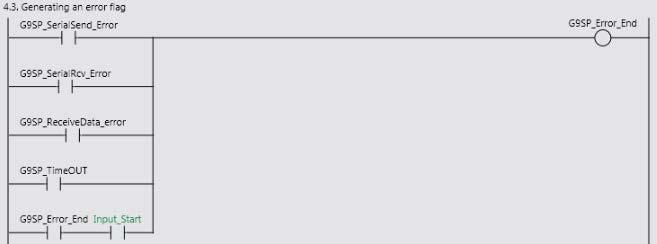
40 9. Project File Name Data type Description G9SP_ReceiveData_error BOOL Receive data error flag. Turns ON when the receive data is not normal Ladder Program Ladder Program Function Configuration The functional configuration of this program is as follows Major Minor classification classification 1. Initialization processing 2. Managing the SerialSend instruction executing status 3. Managing the SerialRcv instruction executing status 4.End processing 1.1. SCU Unit setting 1.2. Setting the G9SP command data 1.3. Generating a checksum 1.4. Converting the send data (USINT BYTE) 1.5. Initializing the response data area and status 1.6. Turning ON the serial communications executing flag and enabling the monitor timer (20 seconds) 2.1. Generating a SerialSend instruction execution flag 2.2. Executing the SerialSend instruction 2.3. Checking for the SerialSend instruction error 2.4. Waiting for data send completion 2.5. Checking for data send completion 2.6. Saving the error status 3.1. Generating a SerialRcv instruction execution flag 3.2. Executing the SerialRcv instruction 3.3. Checking for SerialRcv instruction error 3.4. Checking for data receive completion 3.5. Saving the error status 4.1. Checking the response data 4.2. Generating an error flag Description Preparation for communications. Variables to be used are cleared and initialization settings are performed. The SerialSend instruction is executed and the program waits for the completion of data send operation. The error status is stored in the status area when the operation ends in an error. The SerialRcv instruction is executed and the program waits for the completion of data receive operation. The error status is stored in the status area when the operation ends in an error. The receive data is checked. The error flag is turned ON when an error occurs. 37

41 9. Project File Explanation on Each Functional Component This section shows the details on the functions of this program. 1. Initialization processing No. Overview Description 1.1. SCU Unit setting Sets the Unit number and serial port number of the SCU Unit in the SCU_Inport structure. 38

42 9. Project File No. Overview Description 1.2. Setting the G9SP command data Sets a command sent to G9SP. Data in the red frame are communication receive data and echo back data that can be changed by the user. Any value can be set Generating a checksum Calculates the checksum value of the set command data. 39
 Converts the set command data and calculated checksum value")
43 9. Project File No. Overview Meaning 1.4. Converting the send data (USINT BYTE) Converts the set command data and calculated checksum value into a BYTE array to set them for the SerialSend instruction. 40
 Turns ON G9SP_Excuting that indicates the serial communications are in progress.")
44 9. Project File No. Overview Meaning 1.5. Initializing the response data area Initializes the response area and status area. The status area is initialized to #16#FFFF. and status 1.6. Turning ON the serial communications executing flag and executing the monitor timer (20 seconds) Turns ON G9SP_Excuting that indicates the serial communications are in progress. G9SP send/receive completion check timer (G9SP_Check_Timer) is operated to detect a timeout. When the G9SP send/receive completion check timer times out, G9SP_TimeOUT is turned ON and the error status is stored. 41

45 9. Project File 2. Managing the SerialSend instruction executing status No. Overview Meaning 2.1. Generating a SerialSend instruction execution flag Turns ON G9SP_SerialSend_Excute and starts the SerialSend instruction execution processing if the SerialSend instruction executing flag is not turned ON. Turns OFF this flag when Done flag of the SerialSend instruction is turned ON Executing the Executes the SerialSend instruction. SerialSend instruction 2.3. Checking for a SerialSend instruction Turns ON the G9SP_SerialSend_Error flag when Error flag of the SerialSend instruction is turned ON. error 2.4. Waiting for data send completion Turns ON G9SP_SerialSend_Wait when G9SP_SerialSend_Excute is turned OFF. When the 2.5. Checking data send completion SerialSend instruction executing flag is turned ON, the send processing is completed, G9SP_SerialSend_Wait is turned OFF and G9SP_SerialSend_End is turned ON. 42

46 9. Project File No. Overview Meaning 2.6. Saving error status Sets the following status when the SerialSend instruction ends in an error. Output_Status: #16#FF01 Output_ErrorCode1: ErrorID of SerialSend instruction Output_ErrorCode2: ErrorIDEx of SerialSend instruction Additional Information For information on the error status, refer to 9.7 Error Status List. 43

47 9. Project File 3. SerialRcv instruction execution management No. Overview Description 3.1. Generating a SerialRcv instruction execution flag If G9SP_SerialSend_End is turned ON and the receive completion flag is turned ON, Turns ON G9SP_SerialRcv_Excute and starts the SerialRcv instruction execution processing. This flag is turned OFF when Done flag of the SerialRcv instruction is turned ON. If the receive completion flag is not turned ON for a certain period of time (200 ms), G9SP_SerialRcv_Excute is turned ON and the SerialRcv instruction is executed Executing the Executes the SerialRcv instruction SerialRcv instruction 3.3. Checking for SerialRcv instruction Turns ON the G9SP_SerialRcv_Error flag when the Error flag of the SerialRcv instruction is turned ON. error 3.4. Checking for data receive completion Turns ON G9SP_SerialSend_End when G9SP_SerialRcv_Excute is turned OFF. 44

48 9. Project File No. Overview Meaning 3.4. Checking for data receive completion Turns ON G9SP_SerialSend_End when G9SP_SerialRcv_Excute is turned OFF Saving the error status Sets the next status when the SerialRcv instruction ends in an error. Output_Status: #16#FF02 Output_ErrorCode1: ErrorID of SerialRcv instruction Output_ErrorCode2: ErrorIDEx of SerialRcv instruction Additional Information For derails on the error status, refer to 9.7 Error Status List. 45
 is the same as the fixed data.")
49 9. Project File 4. End processing No. Overview Meaning 4.1. Checking if the response data is normal Checks if the receive response data (G9SP_ResponseData[2] to [5]) is the same as the fixed data. If they are the same, the following data are set. Output_Status: #16#0000 Output_ErrorCode1: #16#0000 Output_ErrorCode2: #16# G9SP_ResponseData_OK: ON 46

50 9. Project File 47
51 9. Project File No. Overview Meaning 4.2. Saving the response data error code If the comparison results are different in No. 4.1, the following data are set. Output_Status: #16#FF03 G9SP_ResponseData_error: ON Output_ErrorCode: G9SP_ResponseData[5]+[2] (Service code+response length) Output_ErrorCode: G9SP_ResponseData[7]+[6]+[4]+[3] (Reserve data at error response+end code) 4.3. Generating an error flag Turns ON G9SP_Error_End when an error occurs. 48
 Communications instruction error Error end (2) Unit error Error end (3) Destination Device error Command")
52 9. Project File 9.6. Timing Charts This section explains the timing charts of the ladder program. The definitions of the timing chart patterns are as follows: Pattern Normal end Error end (1) Communications instruction error Error end (2) Unit error Error end (3) Destination Device error Command Normal Error Normal or error Normal Destination Normal Normal or error Normal or error Error device Response Yes No No Yes (1) Normal end Serial communications being performed. Execute SerialSend instruction. Wait for send data completion. Wait for the receive data. Execute SerialRcv instruction. Completed data receive operation. Check if data is normal. 49
")

 Error end 2 (Unit error) (4)")

53 9. Project File (2) Error end 1 (Communications instruction error) SerialSend instruction error SerialRcv instruction error SerialSend instruction error end SerialSend instruction error end (3) Error end 2 (Unit error) (4) Error end 3 (Destination device error) Timeout error SerialSend not executed. Response data error occurs 50


54 9. Project File 9.7. Error Status List SerialSend/SerialRcv instruction errors This error occurs when the SerialSend/SerialRcv instruction ends in an error. The status code (Output_Status) for each instruction error is shown below. SerialSend instruction error: #16#FF01 SerialRcv instruction error: #16#FF02 Each error status is stored in the following. ErrorID: Output_ErrorCode1, ErrorIDEx: Output_ErrorCode2 [Error status (error code) list] *Output_ErrorCode1 *Output_ErrorCode2 51
55 9. Project File Additional Information For details on the errors, refer to A-3 Error Code Details in the NJ-series Instructions Reference Manual (Cat. No. W502). For troubleshooting the errors, refer to 9-3 Troubleshooting in the CJ-series Serial Communications Units Operation Manual for NJ-series CPU Unit (Cat.No. W494) Destination Device Error The error codes for destination device errors are shown below. The status code (Output_Status) of the destination device error is #16#FF03. [Destination device error code list] Meaning Destination device error code ErrorCode1 Response #16#C3 rightmost length #16#09 #16#00 #16#xx ErrorCode1 Service code #16#CB leftmost #16#xx ErrorCode2 End code #16#0000 rightmost #16#xxxx ErrorCOde2 Reserve data #16#0000 leftmost at error #16#xxxx response Description Normal Error response No response data Other errors Both normal/error response (#CB is received) Other errors Normal Incorrect command Normal Error state Destination device error record function The response data from the Safety Controller include Present Error Information, Error Log Count (Operation Log Count), Error Log (Error Code: Conduction Time), Operation Log (Operation Code: Conduction Time), which are stored in G9SP_ResponseData[100] and the subsequent variables. Note that this project does not detect these errors. Additional Information For details and troubleshooting the destination device errors, refer to Section 13 Troubleshooting in the G9SP Series Safety Controller Operation Manual (Cat. No. Z922). 52

56 9. Project File 53
Connection Guide (RS-232C) OMRON Corporation
 OMRON Corporation") Machine Automation Controller NJ-series General-purpose Serial Connection Guide (RS-232C) OMRON Corporation Ultra Small Multi-code Reader (V400-R2 Series) P567-E1-01 About Intellectual Property Rights
Machine Automation Controller NJ-series General-purpose Serial Connection Guide (RS-232C) OMRON Corporation Ultra Small Multi-code Reader (V400-R2 Series) P567-E1-01 About Intellectual Property Rights
Connection Guide (RS-232C) OMRON Corporation
 OMRON Corporation") Machine Automation Controller NJ-series General-purpose Serial Connection Guide (RS-232C) OMRON Corporation V750 series RFID System P544-E1-01 About Intellectual Property Right and Trademarks Microsoft
Machine Automation Controller NJ-series General-purpose Serial Connection Guide (RS-232C) OMRON Corporation V750 series RFID System P544-E1-01 About Intellectual Property Right and Trademarks Microsoft
Connection Guide (RS-232C) OMRON Corporation
 OMRON Corporation") Machine Automation Controller NJ-series General-purpose Serial Connection Guide (RS-232C) OMRON Corporation ZW-series Displacement Sensor P559-E1-01 About Intellectual Property Right and Trademarks Microsoft
Machine Automation Controller NJ-series General-purpose Serial Connection Guide (RS-232C) OMRON Corporation ZW-series Displacement Sensor P559-E1-01 About Intellectual Property Right and Trademarks Microsoft
CJ Series General-purpose Serial Connection Guide OMRON Corporation V500-R2 Series Fixed Laser-Type Barcode Reader
 CJ Series General-purpose Serial Connection Guide OMRON Corporation V500-R2 Series Fixed Laser-Type Barcode Reader P564-E1-01 About Intellectual Property Rights and Trademarks Microsoft product screen
Machine Automation Controller NJ-series. EtherCAT. Connection Guide. OMRON Corporation. Digital Sensor Communication Unit (E3NW-ECT) P563-E1-01
 P563-E1-01") Machine Automation Controller NJ-series EtherCAT Connection Guide OMRON Corporation Digital Sensor Communication Unit (E3NW-ECT) P563-E1-01 About Intellectual Property Right and Trademarks Microsoft product
Machine Automation Controller NJ-series EtherCAT Connection Guide OMRON Corporation Digital Sensor Communication Unit (E3NW-ECT) P563-E1-01 About Intellectual Property Right and Trademarks Microsoft product
Connection Guide HMS Industrial Networks
 Machine Automation Controller NJ-series EtherCAT(R) Connection Guide HMS Industrial Networks Anybus Communicator P560-E1-02 About Intellectual Property Rights and Trademarks Microsoft product screen shots
Machine Automation Controller NJ-series. EtherNet/IP TM. Connection Guide. OMRON Corporation. CJ2-series Controller P568-E1-01
 Machine Automation Controller NJ-series EtherNet/IP TM Connection Guide OMRON Corporation CJ2-series Controller P568-E1-01 About Intellectual Property Rights and Trademarks Microsoft product screen shots
Machine Automation Controller NJ-series. EtherCAT(R) Connection Guide. Balluff GmbH. Network Interface (BNI ECT-508) P673-E1-01
 Connection Guide. Balluff GmbH. Network Interface (BNI ECT-508) P673-E1-01") Machine Automation Controller NJ-series EtherCAT(R) Connection Guide Balluff GmbH Network Interface (BNI ECT-508) P673-E1-01 About Intellectual Property Rights and Trademarks Microsoft product screen shots
Machine Automation Controller NJ-series EtherCAT(R) Connection Guide Balluff GmbH Network Interface (BNI ECT-508) P673-E1-01 About Intellectual Property Rights and Trademarks Microsoft product screen shots
Machine Automation Controller NJ-series. EtherCAT. Connection Guide. OMRON Corporation. Displacement Sensor(Confocal Fiber Type) (ZW-CE1) P538-E1-01
 (ZW-CE1) P538-E1-01") Machine Automation Controller NJ-series EtherCAT Connection Guide OMRON Corporation Displacement Sensor(Confocal Fiber Type) (ZW-CE1) P538-E1-01 About Intellectual Property Right and Trademarks Microsoft
Machine Automation Controller NJ-series EtherCAT Connection Guide OMRON Corporation Displacement Sensor(Confocal Fiber Type) (ZW-CE1) P538-E1-01 About Intellectual Property Right and Trademarks Microsoft
DELTA ELECTRICS, INC.
 Machine Automation Controller NJ-series EtherCAT(R) Connection Guide DELTA ELECTRICS, INC. EtherCAT Slave Remote module (R1-EC Series) P655-E1-01 About Intellectual Property Rights and Trademarks Microsoft
CJ Series General-purpose Serial Connection Guide (RS-232C) OMRON Corporation Displacement Sensor (ZW-7000 series)
 OMRON Corporation Displacement Sensor (ZW-7000 series)") CJ Series General-purpose Serial Connection Guide (RS-232C) OMRON Corporation Displacement Sensor (ZW-7000 series) P652-E1-01 About Intellectual Property Rights and Trademarks Microsoft product screen
CJ Series General-purpose Serial Connection Guide (RS-232C) OMRON Corporation Displacement Sensor (ZW-7000 series) P652-E1-01 About Intellectual Property Rights and Trademarks Microsoft product screen
Machine Automation Controller NJ-series. EtherCAT. Connection Guide. OMRON Corporation. GX-series Digital I/O Terminal P517-E1-01
 Machine Automation Controller NJ-series EtherCAT Connection Guide OMRON Corporation GX-series Digital I/O Terminal P517-E1-01 Table of Contents 1. Related Manuals... 1 2. Terms and Definition... 2 3. Remarks...
PHOENIX CONTACT GmbH & Co. KG
 Machine Automation Controller NJ-series EtherCAT(R) Connection Guide PHOENIX CONTACT GmbH & Co. KG I/O SYSTEM (Axioline F Series) P621-E1-01 About Intellectual Property Rights and Trademarks Microsoft
Machine Automation Controller NJ-series. EtherCAT(R) Connection Guide. OMRON Corporation. Displacement Sensor (ZW-7000 Series) P651-E1-01
 Connection Guide. OMRON Corporation. Displacement Sensor (ZW-7000 Series) P651-E1-01") Machine Automation Controller NJ-series EtherCAT(R) Connection Guide OMRON Corporation Displacement Sensor (ZW-7000 Series) P651-E1-01 About Intellectual Property Rights and Trademarks Microsoft product
Machine Automation Controller NJ-series EtherCAT(R) Connection Guide OMRON Corporation Displacement Sensor (ZW-7000 Series) P651-E1-01 About Intellectual Property Rights and Trademarks Microsoft product
Connection Guide (TCP/IP) OMRON Corporation
 OMRON Corporation") Machine Automation Controller NJ-series General-purpose Ethernet Connection Guide (TCP/IP) OMRON Corporation V750 series RFID System P543-E1-01 About Intellectual Property Right and Trademarks Microsoft
Machine Automation Controller NJ-series General-purpose Ethernet Connection Guide (TCP/IP) OMRON Corporation V750 series RFID System P543-E1-01 About Intellectual Property Right and Trademarks Microsoft
OMRON Corporation. IO-Link Connection Guide (EtherCAT(R) Host Communications) Machine Automation Controller NJ-series
 Host Communications) Machine Automation Controller NJ-series") Machine Automation Controller NJ-series IO-Link Connection Guide (EtherCAT(R) Host Communications) OMRON Corporation Proximity Sensor (E2E-series IO-Link) [IO-Link Master Unit] OMRON Corporation NX-series
Machine Automation Controller NJ-series IO-Link Connection Guide (EtherCAT(R) Host Communications) OMRON Corporation Proximity Sensor (E2E-series IO-Link) [IO-Link Master Unit] OMRON Corporation NX-series
OMRON Corporation. IO-Link Connection Guide (EtherCAT(R) Host Communications) Machine Automation Controller NJ-series
 Host Communications) Machine Automation Controller NJ-series") Machine Automation Controller NJ-series IO-Link Connection Guide (EtherCAT(R) Host Communications) OMRON Corporation Photoelectric Sensor (E3Z-series IO-Link) [IO-Link Master Unit] OMRON Corporation GX-series
Machine Automation Controller NJ-series IO-Link Connection Guide (EtherCAT(R) Host Communications) OMRON Corporation Photoelectric Sensor (E3Z-series IO-Link) [IO-Link Master Unit] OMRON Corporation GX-series
Connection Guide. SMC Corporation. EtherCAT(R) Machine Automation Controller NJ-series
 Machine Automation Controller NJ-series") Machine Automation Controller NJ-series EtherCAT(R) Connection Guide SMC Corporation EtherCAT Direct input type Step Motor Controller (Servo 24VDC) (JXCE1) P677-E1-01 About Intellectual Property Rights
Machine Automation Controller NJ-series EtherCAT(R) Connection Guide SMC Corporation EtherCAT Direct input type Step Motor Controller (Servo 24VDC) (JXCE1) P677-E1-01 About Intellectual Property Rights
Connection Guide FANUC CORPORATION
 Machine Automation Controller NJ-series EtherCAT(R) Connection Guide FANUC CORPORATION R-30iB Robot Controller P605-E1-01 About Intellectual Property Rights and Trademarks Microsoft product screen shots
EtherCAT(R) Connection Guide IAI Corporation
 Connection Guide IAI Corporation") Machine Automation Controller NJ-series EtherCAT(R) Connection Guide IAI Corporation X-SEL Controller (XSEL-R/S/RX/SX/RXD/SXD) P549-E1-01 About Intellectual Property Rights and Trademarks Microsoft product
Machine Automation Controller NJ-series EtherCAT(R) Connection Guide IAI Corporation X-SEL Controller (XSEL-R/S/RX/SX/RXD/SXD) P549-E1-01 About Intellectual Property Rights and Trademarks Microsoft product
Machine Automation Controller NJ-series. EtherNet/IP TM. Connection Guide. OMRON Corporation. Displacement Sensor (ZW-7000 series) P653-E1-01
 P653-E1-01") Machine Automation Controller NJ-series EtherNet/IP TM Connection Guide OMRON Corporation Displacement Sensor (ZW-7000 series) P653-E1-01 About Intellectual Property Rights and Trademarks Microsoft product
Machine Automation Controller NJ-series EtherNet/IP TM Connection Guide OMRON Corporation Displacement Sensor (ZW-7000 series) P653-E1-01 About Intellectual Property Rights and Trademarks Microsoft product
Machine Automation Controller NJ-series. EtherCAT. Connection Guide. OMRON Corporation. E3X-ECT Sensor Communication Unit (EtherCAT Slave) P529-E1-01
 P529-E1-01") Machine Automation Controller NJ-series EtherCAT Connection Guide OMRON Corporation E3X-ECT Sensor Communication Unit (EtherCAT Slave) P529-E1-01 Table of Contents 1. Related Manuals... 1 2. Terms and
Machine Automation Controller NJ-series EtherCAT Connection Guide OMRON Corporation E3X-ECT Sensor Communication Unit (EtherCAT Slave) P529-E1-01 Table of Contents 1. Related Manuals... 1 2. Terms and
Connection Guide (RS-232C)
") Programmable Controller CJ-series General-purpose Serial Connection Guide (RS-232C) MARS TOHKEN SOLUTION CO.LTD. Fixed Mount 2D Image Reader (MVF-300/500 Series) P679-E1-01 About Intellectual Property
Programmable Controller CJ-series General-purpose Serial Connection Guide (RS-232C) MARS TOHKEN SOLUTION CO.LTD. Fixed Mount 2D Image Reader (MVF-300/500 Series) P679-E1-01 About Intellectual Property
FESTO K.K. IO-Link Connection Guide (EtherCAT(R) Host Communications) Machine Automation Controller NJ-series
 Host Communications) Machine Automation Controller NJ-series") Machine Automation Controller NJ-series IO-Link Connection Guide (EtherCAT(R) Host Communications) FESTO K.K. Proportional pressure regulator valve (VPPM series) [IO-Link Master Unit] OMRON Corporation
Machine Automation Controller NJ-series IO-Link Connection Guide (EtherCAT(R) Host Communications) FESTO K.K. Proportional pressure regulator valve (VPPM series) [IO-Link Master Unit] OMRON Corporation
No.FST-ZTH130453A. CJ Series EtherCAT Connection Guide. OMRON Corporation. E3NW-ECT Digital Sensor Communication Unit P562-E1-01
 No.FST-ZTH130453A CJ Series EtherCAT Connection Guide OMRON Corporation E3NW-ECT Digital Sensor Communication Unit P562-E1-01 About Intellectual Property Right and Trademarks Microsoft product screen shots
Piab AB. IO-Link Connection Guide (EtherCAT(R) Host Communications) Machine Automation Controller NJ-series. Vacuum Ejector (picompact 23 IO-Link)
 Host Communications) Machine Automation Controller NJ-series. Vacuum Ejector (picompact 23 IO-Link)") Machine Automation Controller NJ-series IO-Link Connection Guide (EtherCAT(R) Host Communications) Piab AB Vacuum Ejector (picompact 23 IO-Link) [IO-Link Master Unit] OMRON Corporation NX-series IO-Link
Machine Automation Controller NJ-series IO-Link Connection Guide (EtherCAT(R) Host Communications) Piab AB Vacuum Ejector (picompact 23 IO-Link) [IO-Link Master Unit] OMRON Corporation NX-series IO-Link
CJ-series DeviceNet Connection Guide OMRON Corporation 3G3RX-V1 Series Inverter
 CJ-series DeviceNet Connection Guide OMRON Corporation 3G3RX-V1 Series Inverter P547-E1-01 About Intellectual Property Rights and Trademarks Microsoft product screen shots reprinted with permission from
Omron Adept Technologies,Inc.
 Machine Automation Controller NJ-series EtherNet/IP TM Connection Guide Omron Adept Technologies,Inc. Adept Robot of eplc P649-E1-01 About Intellectual Property Rights and Trademarks Microsoft product
ORIENTAL MOTOR CO., LTD.
 Machine Automation Controller NJ-series EtherCAT(R) Connection Guide ORIENTAL MOTOR CO., LTD. Network Converter NETC01-ECT -Closed Loop Stepping Motor and Driver Package αstep High-Efficiency AR Series
CJ Series EtherNet/IP TM Connection Guide. OMRON Corporation NX-series EtherNet/IP Coupler Unit P656-E1-01
 CJ Series EtherNet/IP TM Connection Guide OMRON Corporation NX-series EtherNet/IP Coupler Unit P656-E1-01 About Intellectual Property Rights and Trademarks Microsoft product screen shots reprinted with
CJ Series IO-Link Connection Guide (EtherNet/IP TM Host Communications) OMRON Corporation Proximity Sensor (E2E-series IO-Link)
 OMRON Corporation Proximity Sensor (E2E-series IO-Link)") CJ Series IO-Link Connection Guide (EtherNet/IP TM Host Communications) OMRON Corporation Proximity Sensor (E2E-series IO-Link) [IO-Link Master Unit] OMRON Corporation NX-series IO-Link Master Unit (NX-ILM[][][])
CJ Series IO-Link Connection Guide (EtherNet/IP TM Host Communications) OMRON Corporation Proximity Sensor (E2E-series IO-Link) [IO-Link Master Unit] OMRON Corporation NX-series IO-Link Master Unit (NX-ILM[][][])
CJ Series EtherNet/IP TM Connection Guide. ABB Ltd. IRC5 Robot Controller P572-E1-01
 CJ Series EtherNet/IP TM Connection Guide ABB Ltd. IRC5 Robot Controller P572-E1-01 About Intellectual Property Rights and Trademarks Microsoft product screen shots reprinted with permission from Microsoft
MARS TOHKEN SOLUTION CO.LTD. Fixed Mount 1D/2D Image Reader (TFIR-31LAN Series)
") No.FST-ZTG140008A CJ Series General-purpose Ethernet Connection Guide MARS TOHKEN SOLUTION CO.LTD. Fixed Mount 1D/2D Image Reader (TFIR-31LAN Series) P606-E1-01 About Intellectual Property Rights and Trademarks
No.FST-ZTG140008A CJ Series General-purpose Ethernet Connection Guide MARS TOHKEN SOLUTION CO.LTD. Fixed Mount 1D/2D Image Reader (TFIR-31LAN Series) P606-E1-01 About Intellectual Property Rights and Trademarks
No. FST-ZTH13079B. Machine Automation Controller NJ-series. EtherCAT Connection Guide. Kollmorgen Corporation Servo Drive (AKD )
") No. FST-ZTH13079B Machine Automation Controller NJ-series EtherCAT Connection Guide Kollmorgen Corporation Servo Drive (AKD ) About Intellectual Property Rights and Trademarks Microsoft product screen
No. FST-ZTH13079B Machine Automation Controller NJ-series EtherCAT Connection Guide Kollmorgen Corporation Servo Drive (AKD ) About Intellectual Property Rights and Trademarks Microsoft product screen
CJ Series EtherNet/IP TM Connection Guide. OMRON Corporation RFID Reader/Writer (V680S-series) P626-E1-01
 P626-E1-01") CJ Series EtherNet/IP TM Connection Guide OMRON Corporation RFID Reader/Writer (V680S-series) P626-E1-01 About Intellectual Property Rights and Trademarks Microsoft product screen shots reprinted with
CJ Series EtherNet/IP TM Connection Guide OMRON Corporation RFID Reader/Writer (V680S-series) P626-E1-01 About Intellectual Property Rights and Trademarks Microsoft product screen shots reprinted with
CJ Series EtherNet/IP TM Connection Guide. Yamaha Motor Co., Ltd. Robot Controller (RCX340) P624-E1-01
 P624-E1-01") CJ Series EtherNet/IP TM Connection Guide Yamaha Motor Co., Ltd. Robot Controller (RCX340) P624-E1-01 About Intellectual Property Rights and Trademarks Microsoft product screen shots reprinted with permission
CJ Series EtherNet/IP TM Connection Guide Yamaha Motor Co., Ltd. Robot Controller (RCX340) P624-E1-01 About Intellectual Property Rights and Trademarks Microsoft product screen shots reprinted with permission
CJ Series EtherNet/IP TM Connection Guide. SMC Corporation Solenoid Valve (SI Unit EX600-SEN#) P657-E1-01
 P657-E1-01") CJ Series EtherNet/IP TM Connection Guide SMC Corporation Solenoid Valve (SI Unit EX600-SEN#) P657-E1-01 About Intellectual Property Rights and Trademarks Microsoft product screen shots reprinted with
CJ Series EtherNet/IP TM Connection Guide SMC Corporation Solenoid Valve (SI Unit EX600-SEN#) P657-E1-01 About Intellectual Property Rights and Trademarks Microsoft product screen shots reprinted with
Machine Automation Controller NJ-series. EtherNet/IP TM. Connection Guide. OMRON Corporation. FZ5-series Vision System P589-E1-01
 Machine Automation Controller NJ-series EtherNet/IP TM Connection Guide OMRON Corporation FZ5-series Vision System P589-E1-01 About Intellectual Property Rights and Trademarks Microsoft product screen
CJ Series EtherNet/IP TM Connection Guide. OMRON Corporation Vision System (FZ5 Series) P588-E1-02
 P588-E1-02") CJ Series EtherNet/IP TM Connection Guide OMRON Corporation Vision System (FZ5 Series) P588-E1-02 About Intellectual Property Rights and Trademarks Microsoft product screen shots reprinted with permission
CJ Series EtherNet/IP TM Connection Guide OMRON Corporation Vision System (FZ5 Series) P588-E1-02 About Intellectual Property Rights and Trademarks Microsoft product screen shots reprinted with permission
Connection Guide IAI Corporation
 Machine Automation Controller NJ-series EtherCAT Connection Guide IAI Corporation Controller SCON-CA P585-E1-01 About Intellectual Property Rights and Trademarks Microsoft product screen shots reprinted
Machine Automation Controller NJ-series. EtherCAT(R) Connection Guide. IAI Corporation. ACON/ACON-CA/ PCON/PCON-CA/ DCON-CA Controller P584-E1-02
 Connection Guide. IAI Corporation. ACON/ACON-CA/ PCON/PCON-CA/ DCON-CA Controller P584-E1-02") Machine Automation Controller NJ-series EtherCAT(R) Connection Guide IAI Corporation ACON/ACON-CA/ PCON/PCON-CA/ DCON-CA Controller P584-E1-02 About Intellectual Property Rights and Trademarks Microsoft
Machine Automation Controller NJ-series EtherCAT(R) Connection Guide IAI Corporation ACON/ACON-CA/ PCON/PCON-CA/ DCON-CA Controller P584-E1-02 About Intellectual Property Rights and Trademarks Microsoft
Omron Adept Technologies,Inc.
 Machine Automation Controller NJ-series EtherNet/IP TM Connection Guide Omron Adept Technologies,Inc. Adept Robot of eplcio P650-E1-01 About Intellectual Property Rights and Trademarks Microsoft product
Machine Automation Controller NX-series CPU Unit User's Manual. FINS Function NX NX NX NX NX NX W596I-E3-01
 Machine Automation Controller NX-series CPU Unit User's Manual FINS Function NX701-1720 NX701-1620 NX102-12 NX102-11 NX102-10 NX102-90 W596I-E3-01 NOTE (1) All rights reserved. No part of this publication
Sysmac Studio Version 1
 Automation Software Sysmac Studio Version 1 Drive Functions Operation Manual SYSMAC-SE2 I589-E1-04 NOTE All rights reserved. No part of this publication may be reproduced, stored in a retrieval system,
SYSMAC CV-series CV500/CV1000/CV2000/CVM1 Programmable Controllers
 Cat. No. W205-E1-04 SYSMAC CV-series CV500/CV1000/CV2000/CVM1 Programmable Controllers SYSMAC CV-series CV500/CV1000/CV2000/CVM1 Programmable Controllers Operation Manual: Host Link System, CV500-LK201
Rockwell Automation ControlLogix 1756-L71 EtherNet/IP Connection Guide. OMRON Corporation. RFID System V680S. V680S RFID System. Cat. No.
 Rockwell Automation ControlLogix 1756-L71 EtherNet/IP Connection Guide OMRON Corporation RFID System V680S V680S RFID System Cat. No. P242I-E-02 About Intellectual Property Right and Trademarks Microsoft
Machine Automation Controller. NJ-series. Troubleshooting Manual NJ NJ NJ W503-E1-01
 Machine Automation Controller NJ-series Troubleshooting Manual NJ501-1300 NJ501-1400 NJ501-1500 W503-E1-01 OMRON, 2011 All rights reserved. No part of this publication may be reproduced, stored in a retrieval
Device/PLC Connection Manuals
 Device/PLC Connection Manuals About the Device/PLC Connection Manuals Prior to reading these manuals and setting up your device, be sure to read the "Important: Prior to reading the Device/PLC Connection
Sysmac Library. User s Manual for Temperature Control Library SYSMAC-XR007 W551-E1-03
 Sysmac Library User s Manual for Temperature Control Library SYSMAC-XR007 W551-E1-03 NOTE All rights reserved. No part of this publication may be reproduced, stored in a retrieval system, or transmitted,
CPU Unit Motion Control
 Machine Automation Controller NJ-series CPU Unit Motion Control User s Manual NJ501-1300 NJ501-1400 NJ501-1500 CPU Unit W507-E1-01 OMRON, 2011 All rights reserved. No part of this publication may be reproduced,
OMRON Corporation PLC SYSMAC CJ1M Series Connection
 OMRON Corporation PLC SYSMAC CJ1M Series Connection Let s Connect to PLC! System Structure GP Product Model Remark GP GLC GP70 Series GP77/77R Series GP2000 Series GLC2000 Series Excepting for handy types.
6-1-6 Types of Errors
 6-1-6 Types of Errors The type of that has occurred can be identified by checking the indicators on the front of the CPU Unit and the Power Supply Unit, or by using the CX-Programmer to check the status.
Configuring EtherCAT BIS V on Omron NJ PLC
 Configuring EtherCAT BIS V on Omron NJ PLC BIS00U9 Obtain the appropriate ESI files for the BIS00U9 either from the Balluff website or on the disk that is included with the processor. Copy them into the
Automation Software. Sysmac Studio. Project Version Control Function Operation Manual SYSMAC-SE2 SYSMAC-TA4 L W589-E1-01
 Automation Software Sysmac Studio Project Version Control Function Operation Manual SYSMAC-SE2 SYSMAC-TA4 L W589-E1-01 NOTE All rights reserved. No part of this publication may be reproduced, stored in
Microframe Corporation
 A0262: RS232 Remote Display Operating Manual A0262-7010 *A0262-7010* A0262 INSTALLATION & SPECIFICATION GUIDE ITEM NO: A0262 REVISION DATE: 11/09 Microframe Corporation 604 S. 12th Street Broken Arrow,
for Project Version Control Function
 Automation Software Sysmac Studio Startup Guide for Project Version Control Function SYSMAC-SE2@@@ SYSMAC-TA4@@L P125-E1-01 NOTE All rights reserved. No part of this publication may be reproduced, stored
EtherNet/IP Monitor Tool Operation Manual
 EtherNet/IP Monitor Tool Operation Manual Introduction This manual documents the operating procedures of the EtherNet/IP Monitor Tool. It does not contain other information, such as precautions. In actual
Startup Guide For EtherCAT Communication Coupler Safety Controllers and I/O Units
 Programmable Multi-Axis Controller Startup Guide For EtherCAT Communication Coupler Safety Controllers and I/O Units CK3E- NY51 -A O025-E1-01 About Copyrights and Trademarks Microsoft product screen shots
B Programmable Terminal NB Series. Practice Guide. Sysmac Studio Variable Table Import NB3Q-TW01B NB5Q-TW01B NB7W-TW01B NB10W-TW01B
 B-181206 Programmable Terminal NB Series Practice Guide Sysmac Studio Variable Table Import NB3Q-TW01B NB5Q-TW01B NB7W-TW01B NB10W-TW01B Introduction This guide provides reference information when designing
G9SP Ethernet IP Communication to Omron s NJ5 PLC s Rev1.0 Mike Wash
 www.infoplc.net G9SP Ethernet IP Communication to Omron s NJ5 PLC s Rev1.0 Mike Wash Summery www.infoplc.net This document will walk you through a step by step setup for communication from a G9SP to a
Cat. No. W585-E1-02 SYSMAC. NX-IO Configurator CXONE-AL D-V4 OPERATION MANUAL
 Cat. No. W585-E1-02 SYSMAC NX-IO Configurator CXONE-AL D-V4 OPERATION MANUAL NOTE All rights reserved. No part of this publication may be reproduced, stored in a retrieval system, or transmitted, in any
NJ NJ-series NJ501 SECS/GEM CPU Unit. Allows SECS/GEM communications in a short time with a simple configuration. Feature
 NJ-series NJ501 SECS/GEM CPU Unit NJ501-1340 CSM_NJ501-1340_DS_E_3_1 Allows SECS/GEM communications in a short time with a simple configuration. The NJ501 SECS/GEM CPU Unit is a NJ-series machine automation
IM3523 IM3533 IM IM3536 LCR METER IM3570 IM7580 IM3590 CHEMICAL IMPEDANCE ANALYZER IMPEDANCE ANALYZER. Communication Instruction Manual
 Communication Instruction Manual IM3523 IM3533 IM3533-01 IM3536 LCR METER IM3570 IM7580 IMPEDANCE ANALYZER IM3590 CHEMICAL IMPEDANCE ANALYZER November 2014 Revised edition 6 IM3570A983-06 14-11H i Contents
TABLE OF CONTENTS. Communication Functions
 TABLE OF CONTENTS Chapter 1: Chapter 2: Chapter 3: Chapter 4: General Features....................................................... 1-1 Functions......................................................
HDV100A3 Command Response Protocol
 HDV100A3 Command Response Protocol Documentation Number: HDV100A3-4115m International Headquarters B+B SmartWorx 707 Dayton Road -- P.O. Box 1040 -- Ottawa, IL 61350 USA Phone (815) 433-5100 -- General
Sysmac Library. User s Manual for EtherCAT 1S Series Library SYSMAC-XR011 W571-E1-02
 Sysmac Library User s Manual for EtherCAT 1S Series Library SYSMAC-XR011 W571-E1-02 NOTE All rights reserved. No part of this publication may be reproduced, stored in a retrieval system, or transmitted,
Safety Network Controller NX-series Communication Control Unit User's Manual. Built-in Function NX-CSG. Communication Control Unit
 Safety Network Controller NX-series Communication Control Unit User's Manual Built-in Function NX-CSG Communication Control Unit NOTE (1) All rights reserved. No part of this publication may be reproduced,
BRAND BOOK. Copyright 2016 WashU Student Union Student Union Brand Guidebook 1
 BRAND BOOK 2019 2016 Copyright 2016 WashU Student Union Student Union Brand Guidebook 1 WHY THIS MATTERS While it is easy for the student body to see the hundreds of group events that take place every
Appendix 3 Using NS-AL002 Converters
 Appendix 3 Using Converters The RS-232C/RS-422A Converter is connected directly to RS-232C port A or B of the, and converts RS-232C communications to RS-422A/RS-485. Any of the Converters listed in Appendix
Operation Software. CNC Operator. Operation Manual SYSMAC-RTNC O032-E1-02
 Operation Software CNC Operator Operation Manual SYSMAC-RTNC O032-E1-02 NOTE All rights reserved. No part of this publication may be reproduced, stored in a retrieval system, or transmitted, in any form,
Sysmac Library. User s Manual for EtherCAT G5 Series Library SYSMAC-XR004 W548-E1-04
 Sysmac Library User s Manual for EtherCAT G5 Series Library SYSMAC-XR004 W548-E1-04 NOTE All rights reserved. No part of this publication may be reproduced, stored in a retrieval system, or transmitted,
Machine Automation Controller NJ-series. Startup Guide. for CPU Unit W513-E1-02
 Machine Automation Controller NJ-series Startup Guide for CPU Unit W513-E1-02 OMRON, 2011 All rights reserved. No part of this publication may be reproduced, stored in a retrieval system, or transmitted,
Flexi Soft Driver SICK AG
 SICK AG Flexi Soft Driver 1 System Configuration... 3 2 External Device Selection... 6 3 Communication Settings... 7 4 Setup Items... 9 5 Cable Diagrams... 15 6 Supported Device... 17 7 Device Code and
Demonstration Screen for Safety CPU
 Programmable Terminal NA-series Practice Guide Demonstration Screen for Safety CPU NA5-15 101 NA5-12 101 NA5-9 001 NA5-7 001 V447-E1-01 2 Introduction This guide provides reference information when using
SAPHIR SIO Driver. Siemens Building Technologies
 Siemens Building Technologies SAPHIR SIO Driver 1 System Configuration... 3 2 External Device Selection... 6 3 Communication Settings... 7 4 Setup Items... 9 5 Cable Diagrams... 14 6 Supported Devices...
Connection Cable Communication 232C Port Method GP 1762-L24BWA. the CPU Unit RS-232C
 System Structure GP Model Product Remark GP GP70 Series GP77 / 77R Series GP2000 Series GLC GLC2000 Series * Information for connecting Handy Type is not on this instruction. PLC CPU Connection Cable Communication
NT31/631 Multi-Vendor Connection
 1-1 System Overview NT31/631 Multi-Vendor Connection Operation Manual Revised February 2001 i OMRON Product References All OMRON products are capitalized in this manual. Names of Devices and Tools PT NTST
Device/PLC Connection Manuals
 Device/PLC Connection Manuals About the Device/PLC Connection Manuals Prior to reading these manuals and setting up your device, be sure to read the "Important: Prior to reading the Device/PLC Connection
BRAND STANDARD GUIDELINES 2014
 BRAND STANDARD GUIDELINES 2014 LOGO USAGE & TYPEFACES Logo Usage The Lackawanna College School of Petroleum & Natural Gas logo utilizes typography, two simple rule lines and the Lackawanna College graphic
NJ-Series Power Supply Unit NJ-PA/PD
 NJ-Series Power Supply Unit CSM_NJ-PA_PD_DS_E_1_2 Powerful power supply unit to supply stable power to the NJ-series controller. Stable power supply is available from the NJ-series CPU Unit to each I/O
Sysmac Library. User s Manual for Weighing Control Library SYSMAC-XR010 W569-E1-02
 Sysmac Library User s Manual for Weighing Control Library SYSMAC-XR010 W569-E1-02 NOTE All rights reserved. No part of this publication may be reproduced, stored in a retrieval system, or transmitted,
USER S MANUAL Enhanced Communication Function
 UM-TS02E -E003 PROGRAMMABLE CONTROLLER PROSEC T2E/T2N USER S MANUAL Enhanced Communication Function Main Menu Contents TOSHIBA CORPORATION Important Information Misuse of this equipment can result in property
Power Mate Series Driver
 FANUC LTD. Power Mate Series Driver 1 System Configuration... 3 2 Selection of External Device... 6 3 Example of Communication Setting... 7 4 Setup Items...10 5 Cable Diagram... 13 6 Supported Device...
Wisconsin Retirement Testing Preparation
 Wisconsin Retirement Testing Preparation The Wisconsin Retirement System (WRS) is changing its reporting requirements from annual to every pay period starting January 1, 2018. With that, there are many
SIMATIC S7 MPI Direct Driver
 Siemens AG SIMATIC S7 MPI Direct Driver 1 System Configuration... 3 2 Selection of... 5 3 Example of Communication Setting... 6 4 Setup Items...13 5 Cable Diagram... 18 6 Supported Device... 25 7 Device
Automationdirect.com. D i r e c t L o g i c S D S N e t w o r k M a s t e r. S m a r t D i s t r i b u t e d. S y s t e m M o d u l e
 Automationdirect.com D i r e c t L o g i c 4 0 5 S D S N e t w o r k M a s t e r S m a r t D i s t r i b u t e d S y s t e m M o d u l e F 4 - S D S Order Number: F4-SDS-M TRADEMARKS Automationdirect.com
Practices Guide. Programmable Terminal NB-series. - Disable/Enable communication with PLCs in Run -time
 Programmable Terminal NB-series Practices Guide - Disable/Enable communication with PLCs in Run -time - Print Screen image + Display Component information - Project file management NB3Q-TW01B NB5Q-TW01B
Manual. PLC Lib: Tc2_DMX. TwinCAT 3. Version: Date:
 Manual PLC Lib: Tc2_DMX TwinCAT 3 Version: Date: 1.5 2017-12-07 Table of contents Table of contents 1 Foreword... 5 1.1 Notes on the documentation... 5 1.2 Safety instructions... 6 2 Introduction... 7
Varispeed SERIES OPTION CARD DeviceNet COMMUNICATION INTERFACE CARD USER'S MANUAL Model: SI-N1
 YASKAWA Varispeed SERIES OPTION CARD DeviceNet COMMUNICATION INTERFACE CARD USER'S MANUAL Model: SI-N1 YASKAWA MANUAL NO. SIBP C730600 01B Copyright 2004 YASKAWA ELECTRIC CORPORATION All rights reserved.
IO-Link System. User s Manual W570-E1-03
 IO-Link System User s Manual W570-E1-03 NOTE All rights reserved. No part of this publication may be reproduced, stored in a retrieval system, or transmitted, in any form, or by any means, mechanical,
Practices Guide OMRON Standard IAG Library
 Programmable Terminal NA-series Practices Guide OMRON Standard IAG Library NA5-15[]101[] NA5-12[]101[] NA5-9[]001[] NA5-7[]001[] V415-E1-04 Introduction This guide provides reference information for the
Startup Guide for Multi-axis Setup and Tuning
 AC Servo System 1S-series Startup Guide for Multi-axis Setup and Tuning R88M-1L[]/-1M[] (AC Servomotors) R88D-1SN[]-ECT (AC Servo Drives) SYSMAC-SE20[][] (Automation Software) I827-E1-01 NOTE All rights
Melsec-Q Link(SIO) Driver
 Driver") Mitsubishi Electric Melsec-Q Link(SIO) Driver 1 System Structure 2 Diagrams 3 Supported Device Addresses 4 Consecutive Device Addresses 5 Environment Setup 6 I/O Manager Configuration 7 Driver Configuration
Mitsubishi Electric Melsec-Q Link(SIO) Driver 1 System Structure 2 Diagrams 3 Supported Device Addresses 4 Consecutive Device Addresses 5 Environment Setup 6 I/O Manager Configuration 7 Driver Configuration
Ph: Fax: Website: Machine Automation Controller NX1P
 Authorised Distributors:Intech Systems Chennai Pvt. Ltd, Chennai-600 032 Ph: +91 44 4353 8888 Fax: 044 4353 7888 E-mail: info@intechchennai.com Website: www.intechchennai.com Machine Automation NX1P 2
MW100 CAN Bus Module Configuration Tool (MX118-CAN-M30/S1) User s Manual
 User s Manual") MW100 CAN Bus Module Configuration Tool (MX118-CAN-M30/S1) User s Manual 1 Contents Before Using the Software... 3 Explanation of Functions... 3 MX118 Part Names and Functions... 3 Operation Guide... 4
MW100 CAN Bus Module Configuration Tool (MX118-CAN-M30/S1) User s Manual 1 Contents Before Using the Software... 3 Explanation of Functions... 3 MX118 Part Names and Functions... 3 Operation Guide... 4
ADVANCED VEHICLE TECHNOLOGIES, Inc. AV. AVT-718 LIN Support. Introduction. Firmware. Hardware. Inc.
 ADVANCED VEHICLE TECHNOLOGIES, Inc. AV Inc. AVT-718 LIN Support This document describes LIN mode operations for the AVT-718 interface. LIN mode was first introduced in the AVT-718 firmware version 2.6.
FRENIC Visual Customizer
 Instruction Manual Inverter Support Software FRENIC Visual Customizer for FRENIC-Ace series Thank you for purchasing our high-performance, multipurpose FRENIC-Ace Series inverter. This manual provides
Machine Automation Controller NJ/NX-series Database Connection CPU Units. User s Manual NX NX NJ NJ CPU Unit W527I-E3-10
 Machine Automation Controller NJ/NX-series Database Connection CPU Units User s Manual NX701-20 NX102-20 NJ501-20 NJ101-20 CPU Unit W527I-E3-10 NOTE All rights reserved. No part of this publication may
IO-Link System. User s Manual W570-E1-04
 IO-Link System User s Manual W570-E1-04 NOTE All rights reserved. No part of this publication may be reproduced, stored in a retrieval system, or transmitted, in any form, or by any means, mechanical,
Sysmac Library. User s Manual for MC Command Table Library SYSMAC-XR002 W545-E1-04
 Sysmac Library User s Manual for MC Command Table Library SYSMAC-XR002 W545-E1-04 NOTE All rights reserved. No part of this publication may be reproduced, stored in a retrieval system, or transmitted,