ReCon T Energy Logger. Installation and connection manual
|
|
|
- Christina O’Brien’
- 6 years ago
- Views:
Transcription

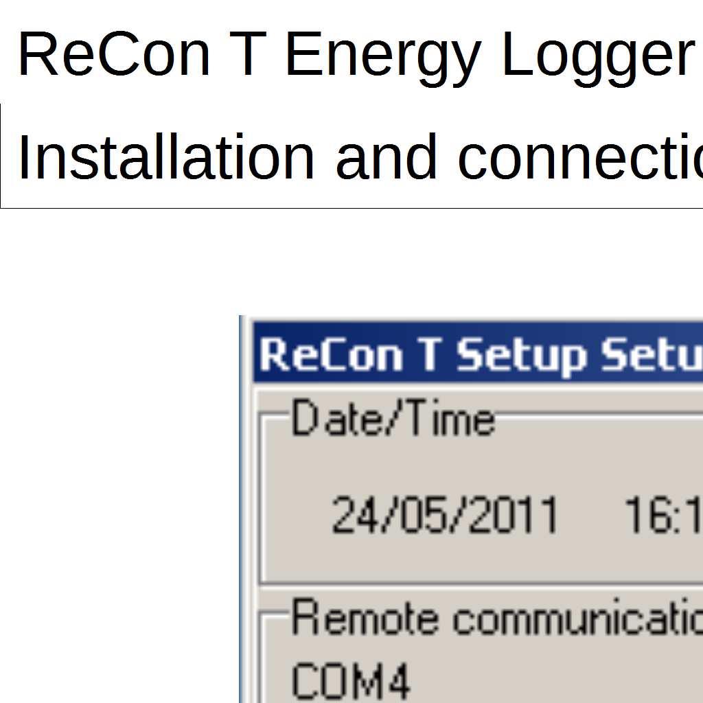
1 ReCon T Energy Logger Installation and connection manual
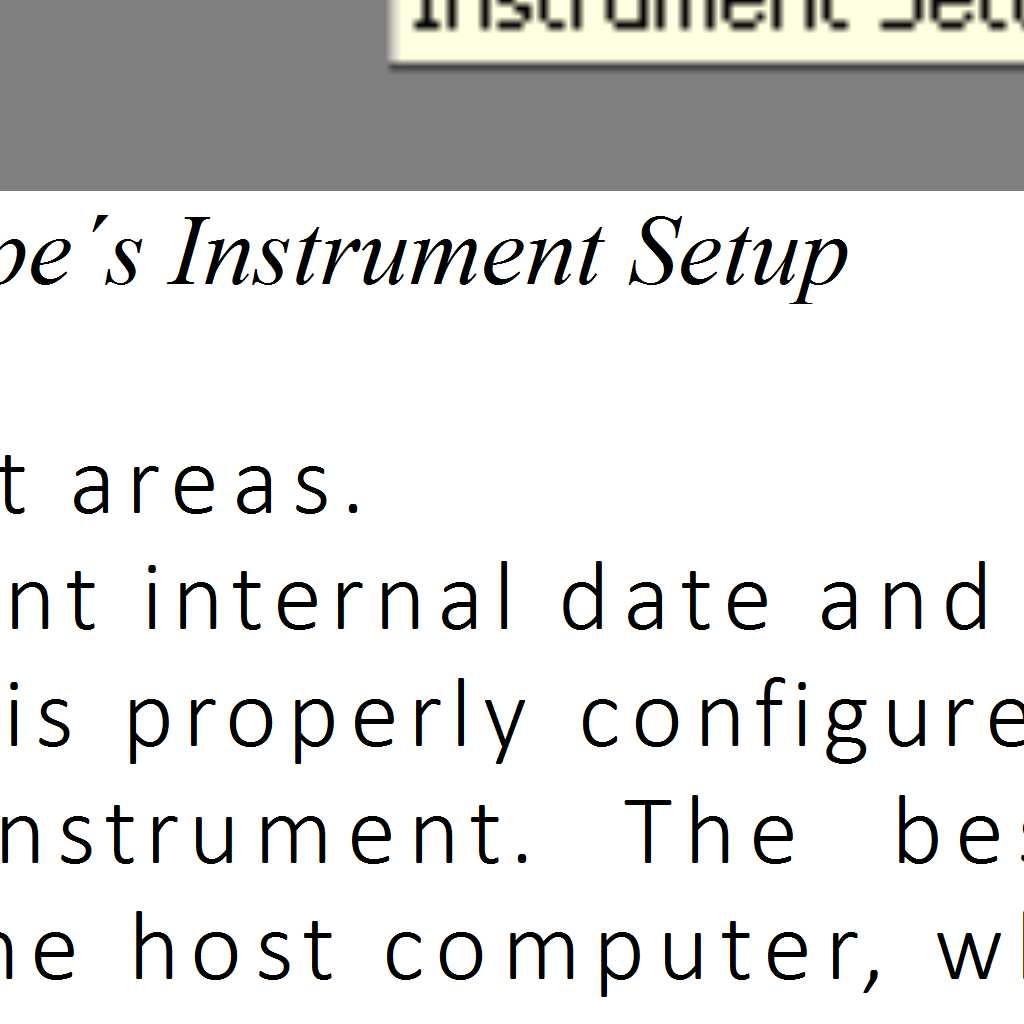
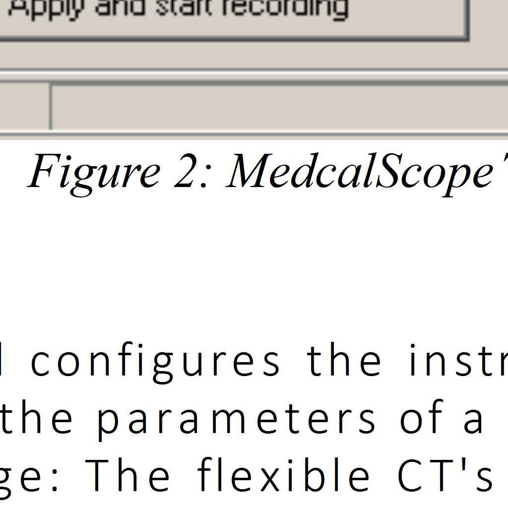
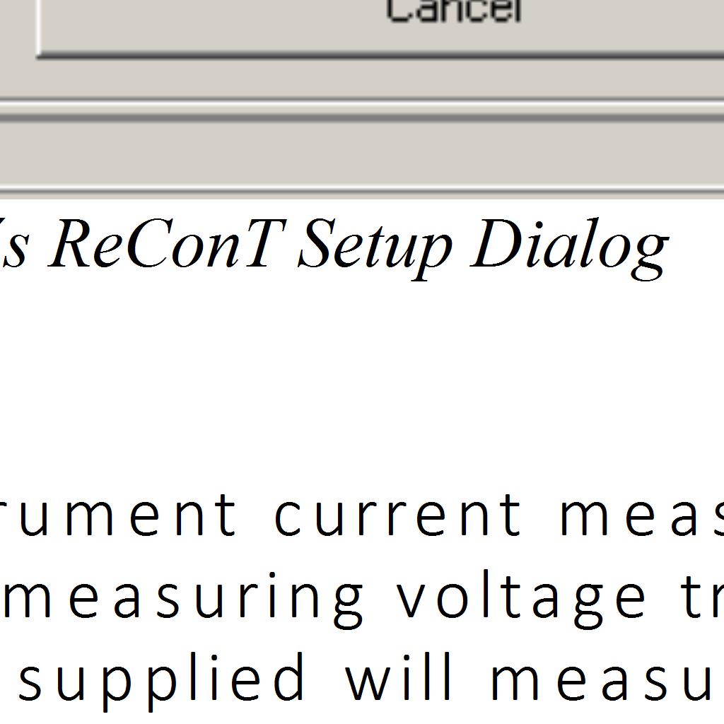
2 Content Index Important safety information... 4 Voltage and current inputs...5 Electric topologies...5 Installing your ReCon T Energy Logger... 6 Setup... 6 Recommended initial checkup... 6 End of recording... 6 Connecting the ReCon T Energy Logger...6 Instrument Set-up... 7 CTs and voltage leads connection diagrams Advanced TCP/IP configuration and use Accessing ReCon T from inside the same LAN...12 Accessing ReCon T from outside the LAN. NAT Configuration...12 Accessing ReCon T via MedcalScope and TCP/IP connection...15 MODBUS in ReCon T...17 Available real time measurements via MODBUS Web server in ReCon T...19 Bluetooth configuration and setup Windows XP Windows Bluetooth software from other manufacturers Figure Index Figure 1: MedcalScope s Instrument Setup 6 Figure 2: MedcalScope s ReConT Setup Dialog 7 Figure 3: MedcalScope s ReCon T Settings 8 Figure 4: Connection for 3-Phase Wye (Star) topology 9 Figure 5: Connection for 3-Phase Delta (Triangle) topology 9 Figure 6: Connection for single phase topology 10 Figure 7: Connection for bi-phase (Split phase) topology 10 Figure 8: MedcalScope s Instrument Name-IP address table 11 Figure 9: Router s status page: detect WAN (public) IP addres 12 Figure 10: Router s configuration utility: NAT table configuration 13 Figure 11: Router s configuration utility: NAT table configuration 13 Figure 12: MedcalScope s IP address table: example of connection to a network outside and inside the PC s network 14 Figure 13: TCP/IP connection in MedcalScope 14 Figure 14: Data Download dialog 15 Figure 15: Real-time measurements via web browser and built-in web server. 18 2/33
3 Revision History Revision Date Comments Author /01/2012 Initial revision RACB /02/2012 Added network related comments CABL /09/2012 Replaced byte with word in MODBUS table CABL /11/2012 Added web server documentation CABL /02/2013 Added information on measurement methods RACB /10/2015 Bluetooth information added MJCG 3/33
4 Important safety information Warning. To avoid electrical shock or fire: 1. Review the entire manual before using the ReCon T Energy Logger and its accessories and observe all warnings and cautions. 2. Do not use exposed metal BNC or banana plug connectors. 3. Do not insert any metal object into the connectors. 4. Do not work alone ever. 5. Avoid connecting the instrument to live voltage. If disconnecting the voltage during the installation is not possible, extreme caution. In any circumstance, always wear protective gloves, face shield, boots, helmet and any other required individual protection equipment. 6. Do not operate the ReCon T Energy Logger in explosive hazardous areas. 7. Use only insulated current probes, test leads, and adapters as supplied with the ReCon T Energy Logger. 8. Before use, inspect the ReCon T Energy Logger, voltage probes, current probes, leads, and accessories for mechanical damage, and replace when damaged. Look for cracks or missing plastic. Pay special attention to the insulation surrounding the connectors. 9. Remove all probes, test leads, and accessories that are not being used. 10. Do not apply input voltages above the rating of the ReCon T Energy Logger as shown on the input panel. 11. Do not apply voltages in excess of the marked ratings of the voltage and current probes. 4/33
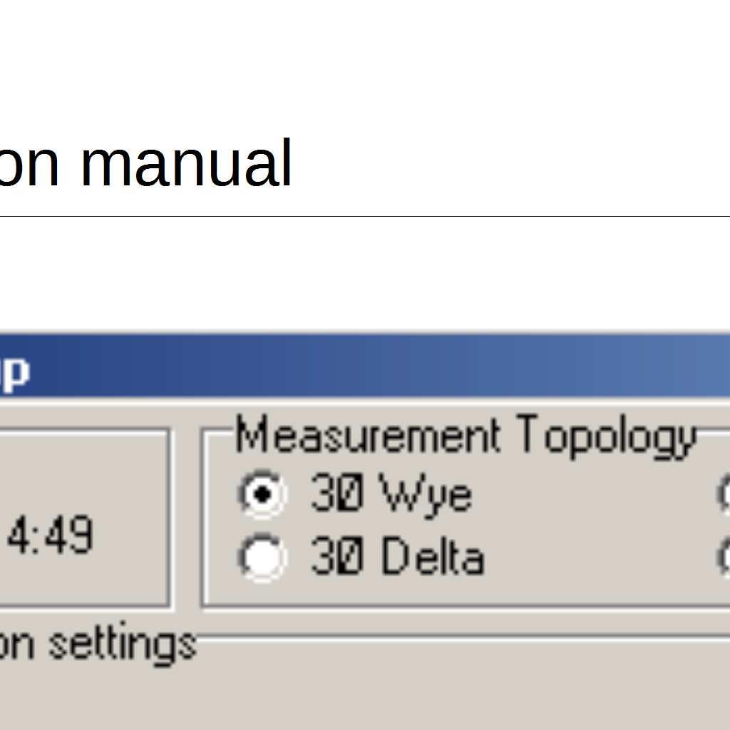
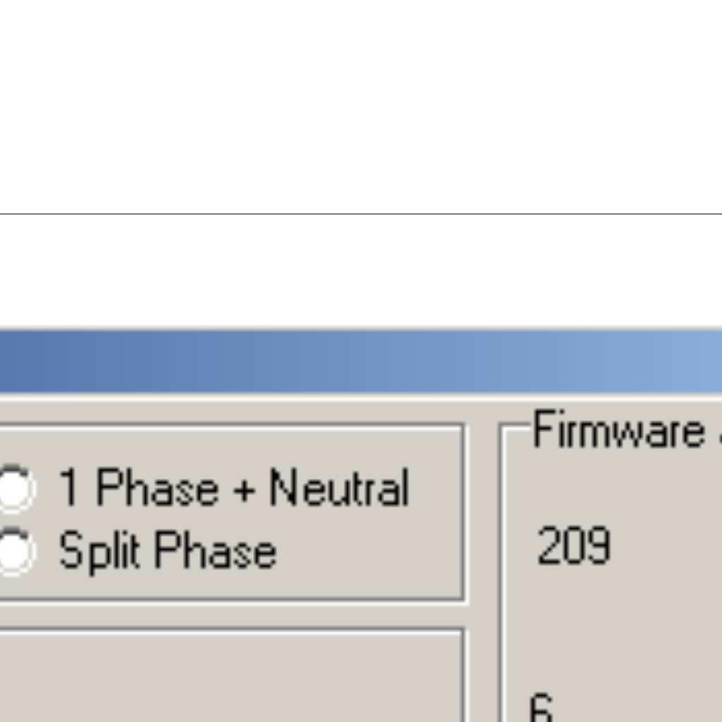
5 Voltage and current inputs ReCon T has integrated voltage input leads as well as flexible current sensors. The 4 Voltage input leads are marked L1, L2, L3 and N (neutral) and are colourcoded according to EU standard: Brown for L1, Black for L2, Grey for L3, Blue for Neutral. The voltage cables are also used for powering the instrument. Due to its extremely low power consumption, this does not affect the measured voltage. Voltage leads are terminated in 4-mm safety banana connectors. Crocodile clips are also supplied for use when suitable female connectors are not available. The same standard color code is used to mark the 3 flexible current sensors. The current sensors have a marked arrow to indicate the positive sense of current. The most common situation you will use the instrument for is analyzing the energy consumption of an installation. Connect the flexible current sensors around the input cables with the arrow pointing from the line to the load. This will result in positive readings for consumed energy. Electric topologies ReCon T supports 4 different measurement topologies. The following table summarizes the connections for the different cases: Topology No. of wires Voltage Connection Current Sensors Wye 4 (L1, L2, L3, N) L1, L2, L3, N L1, L2, L3 Delta 3 (L1, L2, L3) L1, l2, L3. Do not connect Neutral Split-Phase 3 (L1,L2, N) L1, L2, N. Do not connect L3 L1, L2,L3 L1, L2. Do not connect L3 Single- Phase 2 (L1, N) L1, N. Do not connect L2 and L3 L1. Do not connect L2 and L3 The topology is selected using the setup option of MEDCALScope. 5/33
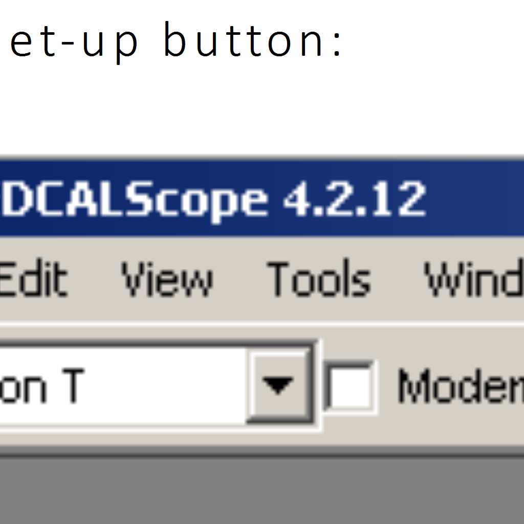
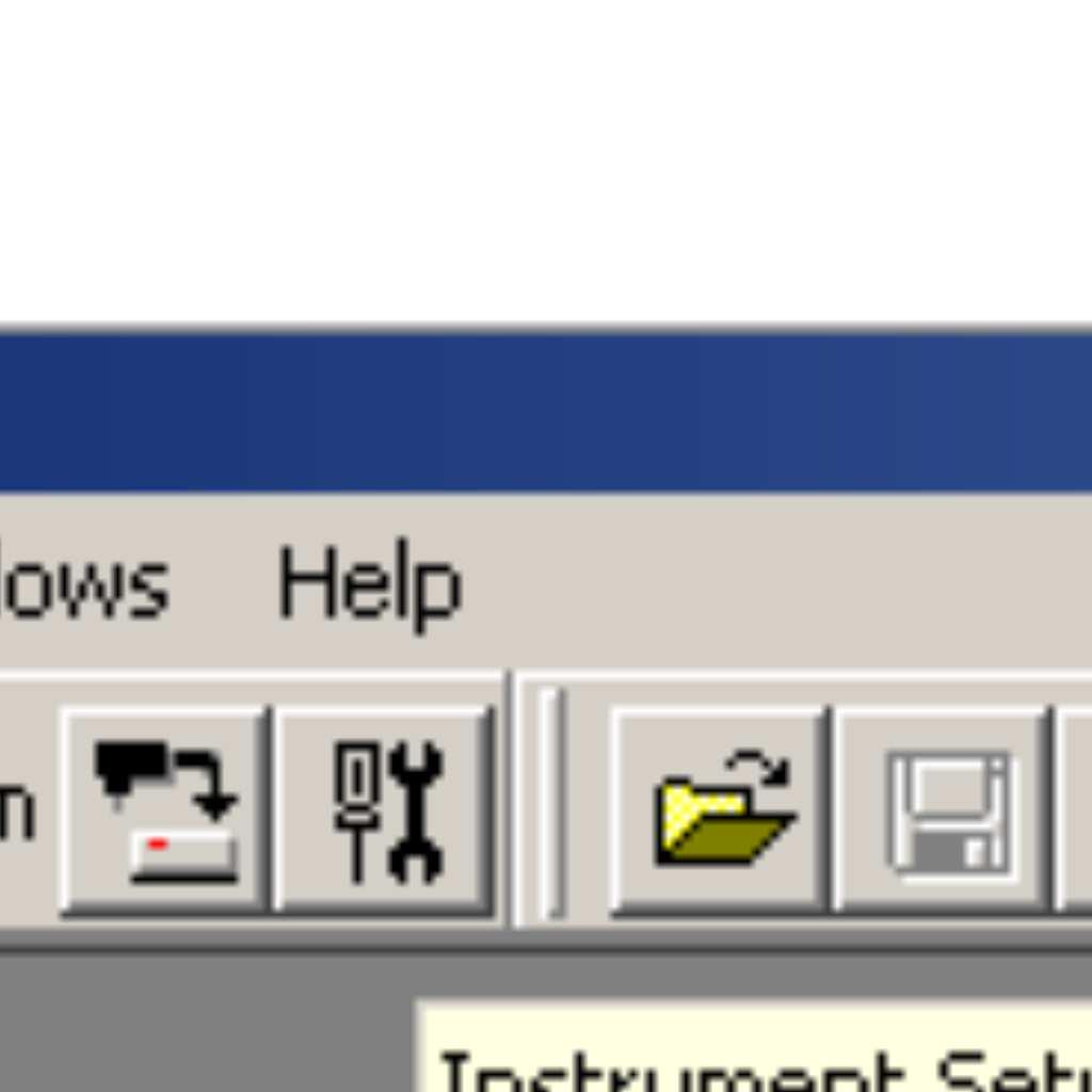
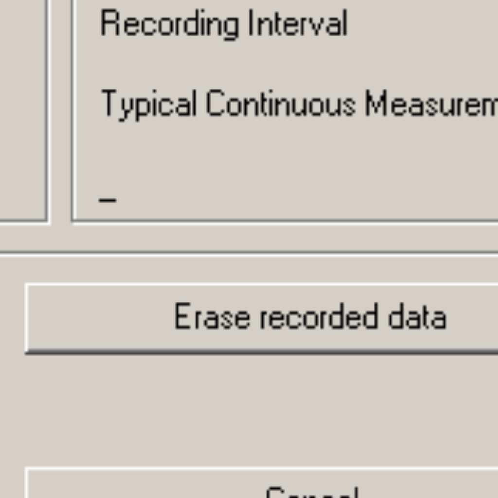
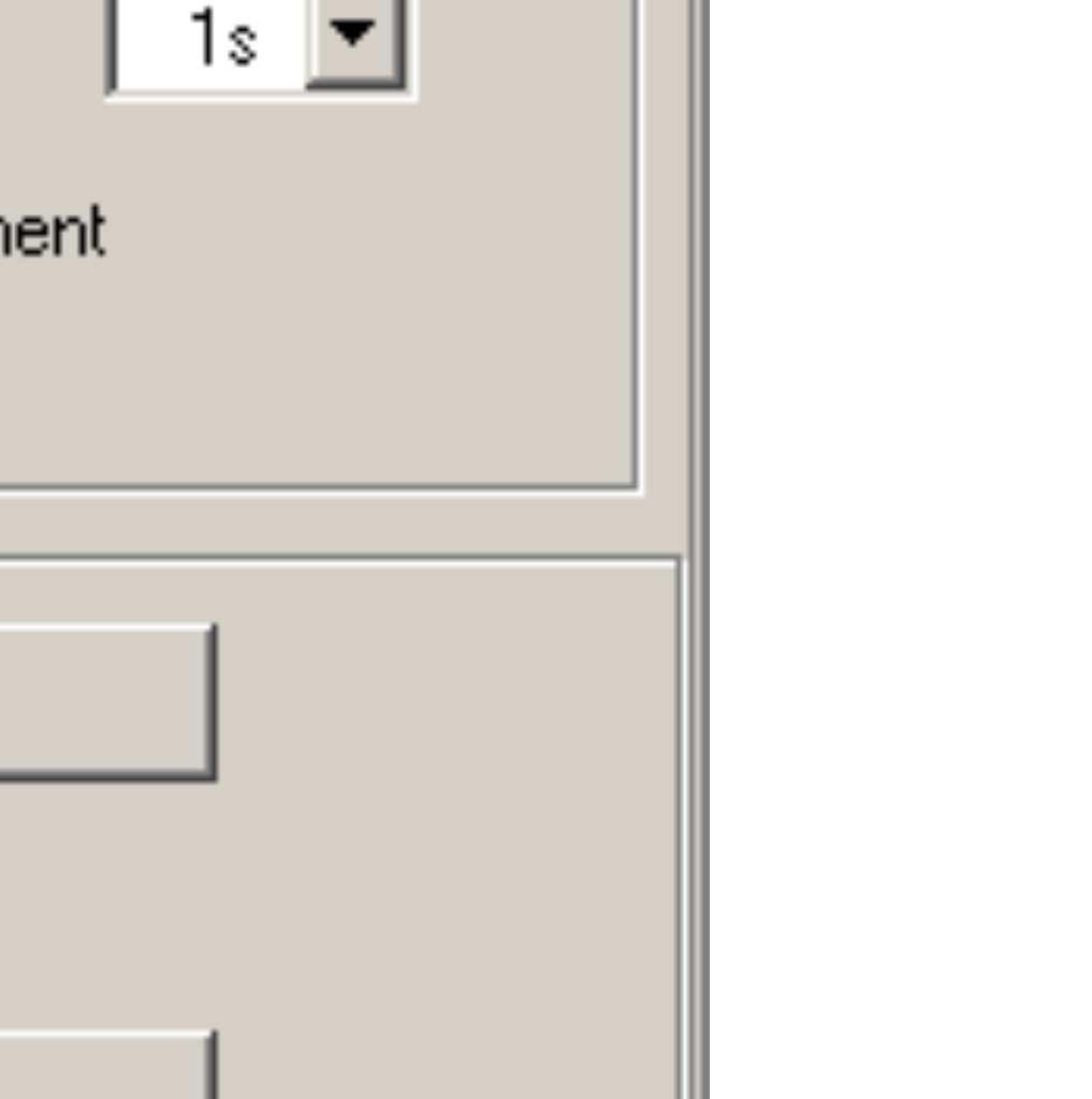
6 Installing your ReCon T Energy Logger This section describes the steps you need to take to set up the ReCon T Energy Logger at the measuring point and begin a recording session. There are three distinct steps for a recording session: Set-up Set-up, connection, and verification of connections and measured signals. This is when you will want to clear the ReCon T Energy Logger memory, make any desired ReCon T Energy Logger setting changes and check the instrument internal clock. Recommended initial checkup Finding then you made a mistake after a long recording session is a frustrating experience. In order to avoid this we strongly recommend doing a quick recording session (maybe with just 1 second recording block) and download immediately just to make sure everything is fine in the instrument set-up and the wiring connection. End of recording Simply disconnect the instrument in order to finish the recording session. Connecting the ReCon T Energy Logger 1. To install the ReCon T Energy Logger, follow these steps: 2. Place the ReCon T Energy Logger at least 1 m away of any live voltage points. 3. The ReCon T Energy Logger can be placed on the floor or a table, or fixed to a wall or pole with the fixed installation kit. 4. Connect the supplied yellow-green crocodile clip to the measuring ground. In order to prevent ground loops make sure the measuring ground is the same as the ground on the power supply socket. 5. Connect the crocodile clips to the corresponding phases in this order: Neutral (Blue), L1 (Brown), L2 (Black), L3 (Gray). 6. After the phase sequence is verified, connect the current clamps to the corresponding phases. The instrument will start measuring as soon as power is applied. There is no need to press the Start/Stop button. When this button is pressed for the first time the measuring and recording are stopped and the instrument display indicates so. Pressing once more will resume the measurement and recording. 6/33


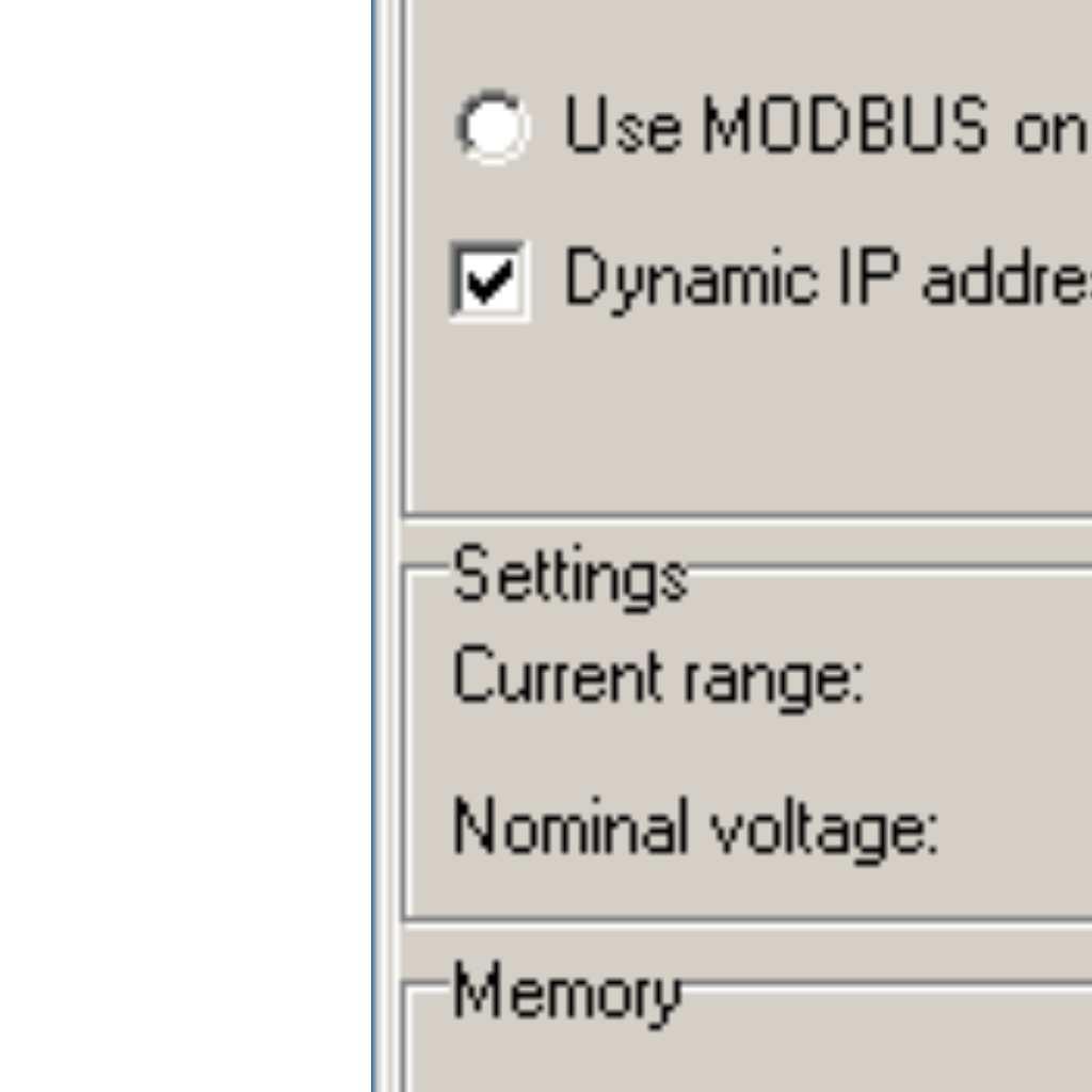
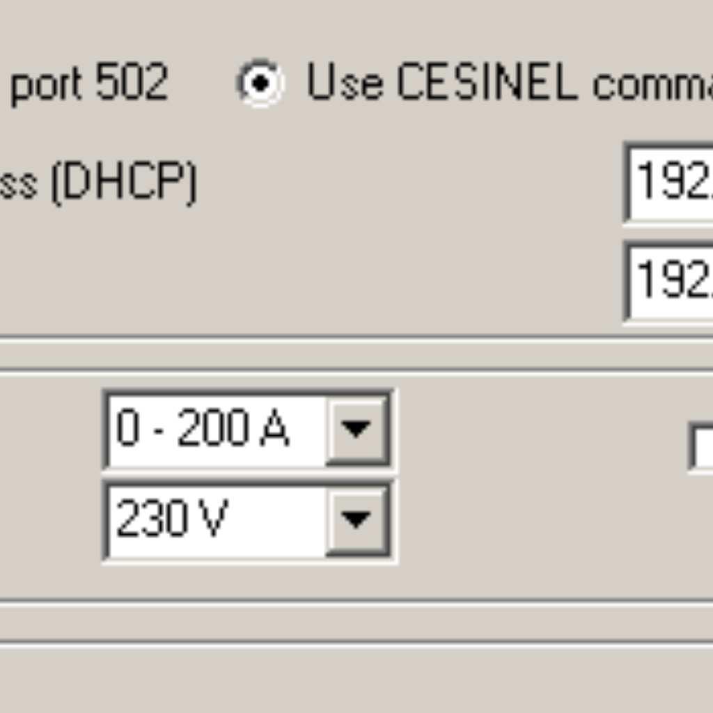
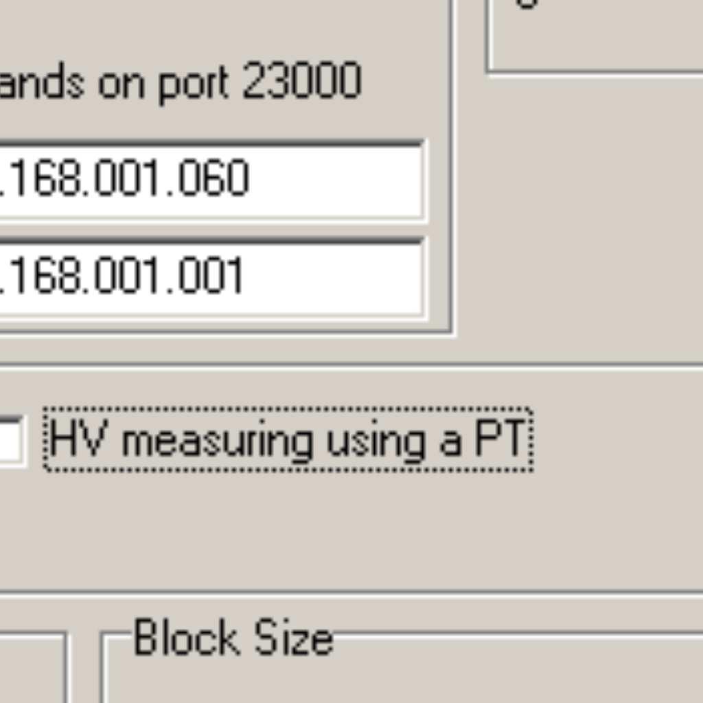
7


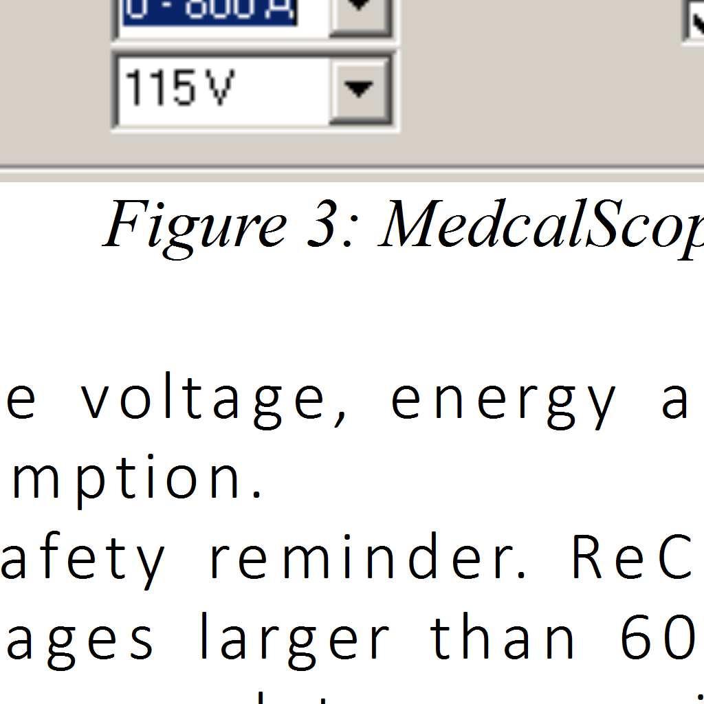
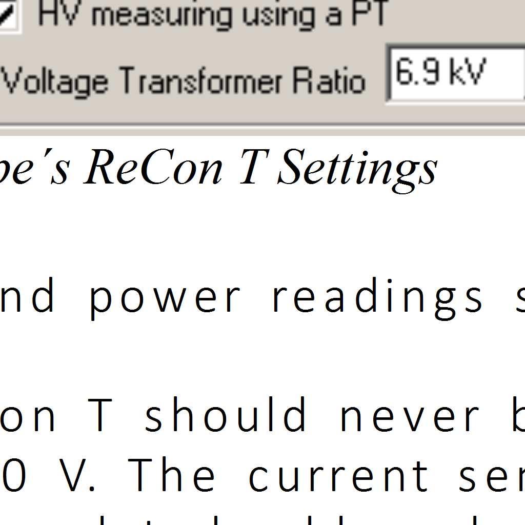
8

9
10 CTs and voltage leads connection diagrams 1. 3Ø Wye (Star) topology: Figure 4: Connection for 3-Phase Wye (Star) topology 2. 3Ø Delta (triangle) topology: Figure 5: Connection for 3-Phase Delta (Triangle) topology 10/33
11 3. 1 Phase with Neutral topology: Figure 6: Connection for single phase topology 4. Split Phase topology: Figure 7: Connection for bi-phase (Split phase) topology 11/33
 from a computer located")
12 Advanced TCP/IP configuration and use It is possible to access one or several ReCon T instruments inside the same LAN (Local Area Network, your facility or office s wireless or wired network), allowing the facility administrator to create a network of measurement points using ReCon T units, gaining access to distributed data (via ModBus, MedcalScope or web browser) from a computer located inside or outside this LAN. Accessing ReCon T from inside the same LAN If the centralized data collector computer is inside the LAN, the local IP address of the unit is enough to access the data. MedcalScope software provides an Instrument Name-IP Address table (which will be stored in memory and, therefore, available every time MedcalScope is run) to ease the connection, provided that ReCon T units are setup properly with static IP addresses, or their dynamic IP addresses 1 are discovered on the fly 2, or the router is configured to always assign the same IP address to the same unit (via its MAC address a unique identifier for each ReCon T-), which is usually done reserving certain IPs for certain MACs (consult your router s manual). Figure 8: MedcalScope s Instrument Name-IP address table Accessing ReCon T from outside the LAN. Router's NAT configuration. If the administrator s computer is outside the LAN, the NAT (Network Address Translation) table of the LAN s router must be setup to redirect ports ( To understand the added complication, user must be aware of that all the incoming and outgoing traffic of an office or facilitie s network (all the data from network computer s web browsers, software ) goes through the unique public IP address of the router (WAN IP address). That is to say that the only 1 MedcalScope allows user to configure static IP addresses or DHCP dynamic addresses 2 There are software tools to discover the elements attached to a network 12/33
.")
13 visible IP address from outside the office or facility is the router s public address (which can be easily guessed searching for my public IP address in Google or detected in the router s configuration utility if the router is DHCP configured, or must be provided by the ISP internet server provider, from whom you rent your internet connection- if a static IP address is rented). Routers are in charge of redirecting incoming data to the local computers (local IP addresses) that requested the data. But if the incoming data is not a response to an outgoing request but a connection from the administrator s computer (via MedcalScope, Modbus software or web browser), there is no other way to redirect traffic apart from configuring the NAT table. This configuration consists just in telling the router to which local IP address and port it must redirect the incoming traffic from a certain port. Figure 9: Router s status page: detect WAN (public) IP addres In the example below, we are telling the router to redirect the incoming data that comes from port to the port 502 of the address , which could correspond to a ReCon T configured to be accessed via ModBus. 13/33

14 Figure 10: Router s configuration utility: NAT table configuration In the example below, we tell the router to redirect incoming port to local port of the IP , which could be a ReCon T configured to use CESINEL protocol via MedcalScope software. Figure 11: Router s configuration utility: NAT table configuration With the configuration of the previous figures, and supposing that our router s public IP address is , we could access data via MedcalScope, Modbus software or web browser from all around the world. The accessed data will depend on the port we use for the connection. 14/33


15 Figure 12: MedcalScope s IP address table: example of connection to a network outside and inside the PC s network Accessing ReCon T via MedcalScope and TCP/IP connection ReCon T instruments may be accessed via TCP/IP connection using MedcalScope software to download recorded data and to setup the instrument. The user must select TCP/IP in the available ports selector. Figure 13: TCP/IP connection in MedcalScope Then, when download or setup actions are fired (through menu items or toolbar buttons), a TCP/IP selector dialog appears (see Figure 12), so that the user can choose an existing item or add a new one to the table with several name-ip address pairs that will be stored by the software. Once the IP address is selected and OK button is clicked, download or setup action continues and the corresponding dialog will show up (see Figure 2 for setup and Figure 14 for download). 15/33

16 Figure 14: Data Download dialog 16/33
17 MODBUS in ReCon T ReCon T instruments have a built-in TCP-MODBUS server that allows the user to access real time data and to integrate the ReCon T in a network with other types of instruments. Regarding the TCP-MODBUS standard, user must be aware of two important features of the ReCon T s TCP-MODBUS server: 1. Only Holding Registers are available to the user (due to the lack of digital inputs and outputs). 2. The Unit Identifier of the TCP-MODBUS header of the requests will be ignored, as the IP of the unit (or the port forwarding method explained before) is used to rout the traffic. Available real time measurements via MODBUS The real time measurements available through the Holding Registers function of TCP-MODBUS are: Addres s Variable Format Units 0 L1. Mean 3 Active power of 1 second reading 4 16 bit signed 5 decimal W 6 1 L2. Mean Active power of 1 second reading 16 bit signed decimal W 2 L3. Mean Active power of 1 second reading 16 bit signed decimal W 3 Total Mean Active Power of 1 second reading 16 bit signed decimal W 4 L1. Mean Reactive power of 1 second reading 16 bit signed decimal var 7 5 L2. Mean Reactive power of 1 second reading 16 bit signed decimal var 6 L3. Mean Reactive power of 1 second reading 16 bit signed decimal var 7 Total Mean Reactive Power of 1 second reading 8 L1. Mean Apparent power of 1 second reading 9 L2. Mean Apparent power of 1 second reading 10 L3. Mean Apparent power of 1 second reading 16 bit signed decimal var 16 bit unsigned decimal 16 bit unsigned decimal 16 bit unsigned decimal VA 8 VA VA 3 Only average values are available in real time. For maximum an minimum vales, use MedcalScope. 4 Real time measurements are updated every second synchronized with the internal clock. As TCP-MODBUS is asynchronous, measurements are not initiated on MODBUS demand but on the internal real time clock. 5 Two s complement sign-magnitude format 6 See Address 34 for power scaling comments 7 See Address 34 for power scaling comments 8 See Address 34 for power scaling comments 17/33
18 Addres s Variable Format Units 11 Total Mean Apparent Power of 1 second reading 16 bit unsigned decimal 12 L1. Mean RMS Voltage of 1 second reading 16 bit unsigned decimal 13 L2. Mean RMS Voltage of 1 second reading 16 bit unsigned decimal 14 L3. Mean RMS Voltage of 1 second reading 16 bit unsigned decimal 15 L1. Mean RMS Current of 1 second reading 16 bit unsigned decimal 16 L2. Mean RMS Current of 1 second reading 16 bit unsigned decimal 17 L3. Mean RMS Current of 1 second reading 16 bit unsigned decimal 18 L1. Highest word 9 of Accumulated Active Energy L1. Higher word of Accumulated Active Energy 20 L1. Lower word of Accumulated Active Energy 21 L1. Lowest word of Accumulated Active Energy 22 L2. Highest word of Accumulated Active Energy 23 L2. Higher word of Accumulated Active Energy 24 L2. Lower word of Accumulated Active Energy 25 L2. Lowest word of Accumulated Active Energy 26 L3. Highest word of Accumulated Active Energy 27 L3. Higher word of Accumulated Active Energy 28 L3. Lower word of Accumulated Active Energy 29 L3. Lowest word of Accumulated Active Energy 16 bit 16 bit 16 bit VA V/100 V/100 V/100 A/100 A/100 A/ bit Wh 16 bit 16 bit 16 bit 16 bit Wh 16 bit 16 bit 16 bit 30 Highest byte of Total Accumulated Active 16 bit 16 bit Wh 9 MODBUS Holding Registers are 16 bits variables, so we need 4 variables to represent the 64-bit signed (two s complement) Accumulated Energy. 10 Accumulated Energy: total amount of energy since manual erase (via MedcalScope). Preserved on power-off. 18/33
19 Addres s Variable Format Units Energy 31 Higher byte of Total Accumulated Active Energy 32 Lower byte of Total Accumulated Active Energy 33 Lowest byte of Total Accumulated Active Energy 16 bit 16 bit 16 bit Wh 34 Power Divisor bit unsigned ReCon T built-in web-server. ReCon T instruments include a built-in http server (web server) that allows the user to see real time measurements in a web browser via a web page whose URL is the IP address of the instrument (see previous sections on how to access a ReCon T from outside/inside its LAN). The web page has an auto-refresh interval of 5 seconds, although the user may always refresh the web page via web browser commands. Use of simultaneous access to web browser and MODBUS or CESINEL remote commands is discouraged. In the next figure, user can see how to connect to a ReCon T whose IP address is from inside the same LAN via a web browser. 11 Required divisor to fit Power into 16 bit variables. One of three values, related to Current Range: 10 (200 A), 50 (800 A) or 200 (3200 A). By knowing the current range or by requesting Power Divisor via MODBUS, user can convert measurements to real units. 19/33


20 Bluetooth configuration and use For ReCon T devices with Bluetooth communications available, you must follow different steps according to your PC's operating system. Windows XP 1. Start / Control panel / Bluetooth devices / Add a new Bluetooth device 20/33


21 2. Make sure that you check the My device is configured and ready to be detected option 3. The PC starts looking for Bluetooth devices. This process may take some time. 21/33


22 4. The Recon T instrument is detected. 5. Select the Use the access key provided with the documentation option, and then type that key in the associated field. 22/33


23 6. The PC will connect to the ReCon T instrument, exchange access keys, and install virtual serial ports. 7. Windows XP finds the ReCon T instrument and installs it as a virtual serial port. 23/33

24 8. After the process is done, Windows will provide information about the virtual serial ports created. Since the ReCon T instrument will never start the communication, and will always be treated as slave during the process, we must pay attention to the Output serial port. 9. The ReCon T instrument will appear as a linked device. 24/33


25 10. It is recommended to check the Show the Bluetooth icon in the notification area option. 11. Open MEDCALScope and select the output serial port created for the ReCon T Bluetooth instrument. Now you will be able to communicate with the instrument in the usual manner. 25/33

26 12. If you are not going to work with the Bluetooth ReCon T device for a long time, it is recommended to remove the instrument from the PC, since the virtual serial ports are not automatically removed, and new ones are created for every new device added. 26/33


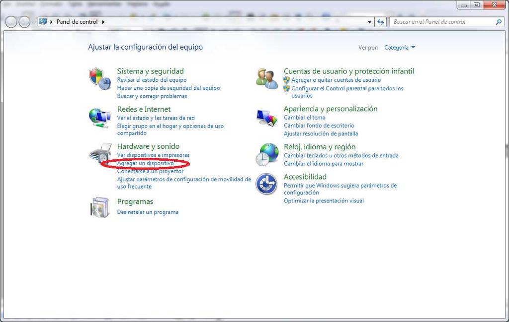
27 Windows 7 1. Start / Control panel / Add new device


28 2. The ReCon T instrument will appear once detected. Select it, and then click on the Write the pairing key option. 28/33


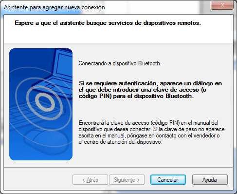
29 3. Type the provided key and click Next. The PC will connect with the ReCon T instrument and will install the device controller software. A pop-up message will appear when the process is finished, and the device will be ready to be used. 29/33


30 4. Right click on the ReCon T icon, and select Properties. Go to Services tab, and the virtual serial port identifier will be displayed there. 5. If you are not going to work with the Bluetooth ReCon T device for a long time, it is recommended to remove the instrument from the PC, since the virtual serial ports are not automatically removed, and new ones are created for every new device added. 30/33
, you must use the tools provided by the manufacturer. 1.")
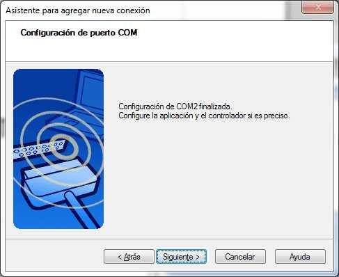
31 Bluetooth software from other manufacturers In case that your personal computer works with a Bluetooth stack different than the one provided by Windows (Toshiba, for instance), you must use the tools provided by the manufacturer. 1. Create a new connection 31/33
32 32/33

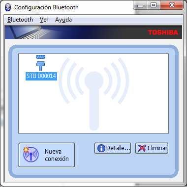
33 2. An access key will be required the first time that you try to connect with the ReCon T instrument, either using MEDCALScope or the assistant. 33/33
ReCon T Energy Logger
 Installation and connection manual Content Index Important safety information...4 Warning. To avoid electrical shock or fire:...4 Voltage and current inputs...5 Electric topologies...5 Installing your
STYLITIS-POWER OPERATOR S GUIDE
 STYLITIS-POWER OPERATOR S GUIDE Copyright 2008-2016, SYMMETRON Electronic Applications. Second edition in English. April 2016. No part of this publication may be reproduced, stored in retrieval system,
QUICK SETUP GUIDE. BCM2 Series Branch Circuit Monitors. Safety Information. Equipment Maintenance and Service. Raritan DANGER!
 QUICK SETUP GUIDE BCM2 Series Branch Circuit Monitors Safety Information DANGER! HAZARD OF ELECTRIC SHOCK, EXPLOSION, OR ARC FLASH Follow safe electrical work practices. See NFPA 70E in the USA, or applicable
Fluke 43B. Power Quality Analyzer. Getting Started. EN June Fluke Corporation, All rights reserved. Printed in The Netherlands.
 Power Quality Analyzer EN June 2005 2001-2005 Fluke Corporation, All rights reserved. Printed in The Netherlands. All product names are trademarks of their respective companies. PLACING ORDERS AND GETTING
Wa r n i n g-wa r n i n g-wa r n i n g
 Installation Instructions of the Power Analyzer Wa r n i n g-wa r n i n g-wa r n i n g Read and understand this manual before connecting device. Death, fire or serious injury can occur from using equipment
Simple Logger II Series
 Simple Logger II Series Quick Start Guide ENGLISH www.aemc.com CHAUVIN ARNOUX GROUP Statement of Compliance Chauvin Arnoux, Inc. d.b.a. AEMC Instruments certifies that this instrument has been calibrated
BCM2 Series Branch Circuit Monitors Quick Setup Guide
 BCM2 Series Branch Circuit Monitors Quick Setup Guide Safety Information DANGER! HAZARD OF ELECTRIC SHOCK, EXPLOSION, OR ARC FLASH Follow safe electrical work practices. See NFPA 70E in the USA, or applicable
QUICK SETUP GUIDE. BCM2 Series Branch Circuit Monitors. Safety Information. Equipment Maintenance and Service. Product Overview. Raritan DANGER!
 QUICK SETUP GUIDE BCM2 Series Branch Circuit Monitors Safety Information DANGER! HAZARD OF ELECTRIC SHOCK, EXPLOSION, OR ARC FLASH Follow safe electrical work practices. See NFPA 70E in the USA, or applicable
Model P4017 Single Channel USB Oscilloscope. Quick Start Guide
 Model P4017 Single Channel USB Oscilloscope Quick Start Guide General Warranty BNC warrants that the product will be free from defects in materials and workmanship for 3 years from the date of purchase
BDL-SERIES BATTERY DATA LOGGER
 BDL-SERIES BATTERY DATA LOGGER User Manual V1.1 1 Contents 1. Introduction... 3 1.1 Overview... 3 1.2 Technical Specification... 4 1.3 Composition... 5 2. DAC Wiring Connection... 5 2.1 Cell DAC Connection...
QUICK SETUP GUIDE PMC-1000, PMC-1001, PMM-1000, PMB PM Series Power Meter. Safety Information. Equipment Maintenance and Service.
 PM Series Power Meter QUICK SETUP GUIDE PMC-1000, PMC-1001, PMM-1000, PMB-1960 Safety Information DANGER! HAZARD OF ELECTRIC SHOCK, EXPLOSION, OR ARC FLASH Follow safe electrical work practices. See NFPA
ILF-100WD User Manual. Router Watchdog / Connection Monitor 2007 Stealth Laboratories, LLC Patent Pending
 ILF-100WD User Manual Router Watchdog / Connection Monitor 2007 Stealth Laboratories, LLC Patent Pending Rev. 1.17 02/24/2009 Table of Contents Installation and Configuration...3 Network Configuration...4
Innovative Electronics for a Changing World INDEX
 Innovative Electronics for a Changing World INDEX 1. SYSTEM DESCRIPTION 2. BOARD CONNECTIONS terminals and indicators 3. CONNECTION DIAGRAM 4. START UP GUIDE and passwords 5. HOME PAGE 6. STATUS PAGE 7.
Dual channel temperature logger with two voltage inputs 0-5V Instruction Manual
 LOGGER S0541 Dual channel temperature logger with two voltage inputs 0-5V Instruction Manual Instruction Manual for use of S0541 logger Instrument is designed for measurement and record of temperature
PM Series Power Meter
 PM Series Power Meter Quick Setup Guide - PMC-1000, PMC- 1001, PMM-1000, PMB-1960 Safety Information DANGER! HAZARD OF ELECTRIC SHOCK, EXPLOSION, OR ARC FLASH Follow safe electrical work practices. See
99 Washington Street Melrose, MA Phone Toll Free Visit us at
 99 Washington Street Melrose, MA 02176 Phone 781-665-1400 Toll Free 1-800-517-8431 Visit us at www.testequipmentdepot.com Table of Contents 1. General Safety Requirements... 1 2. Safety Terms and Symbols...
A+ Guide to Software: Managing, Maintaining, and Troubleshooting, 5e. Chapter 8 Networking Essentials
 A+ Guide to Software: Managing, Maintaining, and Troubleshooting, 5e Chapter 8 Networking Essentials Objectives Learn about the protocols and standards Windows uses for networking Learn how to connect
Wireless-G Router User s Guide
 Wireless-G Router User s Guide 1 Table of Contents Chapter 1: Introduction Installing Your Router System Requirements Installation Instructions Chapter 2: Preparing Your Network Preparing Your Network
RS Stock No Instruction Manual RS Input Data Logging Thermometer
 RS Stock No. 730-0458 Instruction Manual RS-1384 4 Input Data Logging Thermometer EN FR IT DE ES TABLE OF CONTENTS / EN TITLE TABLE OF CONTENTS PAGE 1. INTRODUCTION FEATURE... 1 2. SPECIFICATIONS... 2
Enercept H8035/H8036 Modbus Energy Meter Networked kw/kwh Transducers
 POWER MONITORING INSTALLATION GUIDE Enercept H8035/H8036 Modbus Energy Meter Networked kw/kwh Transducers US Patent No. 6,373,238 Installer's Specifications Input Voltage 208 to 480 VAC Number of Phases
PITE 3926C Battery Data Logger User Manual
 PITE 3926C Battery Data Logger User Manual P-140922-V1.3 4/F, Bldg A, Chiwan Industrial Park, Shaodi Rd., Chiwan, Shekou Area, Shenzhen, China TEL: +86-755-2680 5759 FAX: +86-755-2688 0310 www.pitetech.com
Sentinel AC & DC Current Logger Models SDL A401 & SDL A402
 Sentinel AC & DC Current Logger Models SDL A401 & SDL A402 Model SDL A402 The Sentinel Current Logger Models SDL A401 and SDL A402 are designed for use with AEMC detachable current probes or AmpFlex sensors
Interpretype Bluetooth Setup Procedure
 This information is for configuring the Interpretype to communicate using the Bluetooth Connectivity Kit. To communicate using LAN or Wi-Fi in the full featured version of our software, please refer to
INSTALLATION INSTRUCTIONS
 INSTALLATION INSTRUCTIONS BACnet Communication Card RXRX-AY01 RECOGNIZE THIS SYMBOL AS AN INDICATION OF IMPORTANT SAFETY INFORMATION! WARNING THESE INSTRUCTIONS ARE INTENDED AS AN AID TO QUALIFIED, LICENSED
User Guide. DOCSIS 3.0 High Speed Cable Modem TC7650 REV
 User Guide DOCSIS 3.0 High Speed Cable Modem TC7650 REV1.1.0 1910011895 Contents About This Guide..................................................... 1 Chapter 1. Get to Know Your Modem................................
Thermo-Anemometer Data Logger Model 1227
 Thermo-Anemometer Data Logger Model 1227 Quick Start Guide ENGLISH www.aemc.com Statement of Compliance Chauvin Arnoux, Inc. d.b.a. AEMC Instruments certifies that this instrument has been calibrated using
User manual PROFIBUS C/Q 15/96 MCU
 Page 1 of 12 SUMMARY 1. DESCRIPTION.... 2 2. AVAILABLE VARIABLES... 3 3. MODULES DESCRIPTION... 5 4. PROFIBUS WIRING... 10 5. ADDRESS SETTING.... 10 6. STATUS LED INDICATIONS... 11 7. TROUBLE SHOOTING...
MIU-1000 v. Revised: 4/20/2009. Copyright 2008, Traf-SYS, Inc.
 MIU-1000 v 2.6g Revised: 4/20/2009 Copyright 2008, Traf-SYS, Inc. Contents Introduction... 3 Setting up your MIU-1000 for the first time... 3 Connections... 3 Connecting with a Serial Cable... 3 Connecting
NEW ERA METER. Installation & Operation Guide NE METER
 NEW ERA METER Installation & Operation Guide NE METER Autoranging Power Supply Installation Diagnostics Per Phase Voltage & Current kwh, Demand and TOU 0.2% Accuracy -40 C to +85 C Watertight Enclosure
DataNet Installation Guide + Quick Start Guide Updated: August 2008
 DataNet Installation Guide + Quick Start Guide Updated: August 2008 This document contains instructions for downloading and installing the DataNet software, supporting Fourier Systems DataNet data logging
The MSM335 is a Wi-Fi Alliance authorized Wi-Fi CERTIFIED product. The Wi-Fi CERTIFIED Logo is a certification mark of the Wi-Fi Alliance.
 The MSM335 is a Wi-Fi Alliance authorized Wi-Fi CERTIFIED product. The Wi-Fi CERTIFIED Logo is a certification mark of the Wi-Fi Alliance. In MSM335 Access Point Quickstart This Quickstart shows you how
Models PEL 102 & PEL 103
 V1 V2 V3 N 1000V CAT III I1 I2 I3 600V CAT IV POWER & ENERGY LOGGER ON/OFF START/STOP Special product features MEASURES '''' ''' D E M A N D $ TRACKS E N E R G Y C O S T POWER QUALITY ANALYZERS, METERS
PowerMust Office Uninterruptible Power System
 USER MANUAL E PowerMust Office Uninterruptible Power System 614-05737-05 28-2PRO000001 IMPORTANT SAFETY INSTRUCTIONS SAVE THESE INSTRUCTIONS This manual contains important instructions for Models PowerMust
Gigaset Router / en / A31008-E105-B / cover_front_router.fm / s Be inspired
 s Be inspired Table of Contents Table of Contents Safety precautions........................... 3 The Gigaset Router........................... 3 Features and Benefits..................................................
QUICK START USER GUIDE. Data Logger Model L452
 QUICK START USER GUIDE Data Logger Model L452 Statement of Compliance Chauvin Arnoux, Inc. d.b.a. AEMC Instruments certifies that this instrument has been calibrated using standards and instruments traceable
Computer Essentials Session 1 Lesson Plan
 Note: Completing the Mouse Tutorial and Mousercise exercise which are available on the Class Resources webpage constitutes the first part of this lesson. ABOUT PROGRAMS AND OPERATING SYSTEMS Any time a
CommLink IV Technical Guide
 www.wattmaster.com CommLink IV Technical Guide Table of Contents General Information... 3 CommLink IV Overview...3 Optional IP Module Kit...3 Optional Remote Link II...3 Installing CommLink IV ONLY...3
PTZ NETWORK CAMERA SERIES
 353Z PTZ NETWORK CAMERA SERIES INSTALLATION GUIDE Please read instructions thoroughly before operation and retain it for future reference. N244_245_V0.9 Powerful Remote Surveillance Distance makes no difference
Troubleshooting Microsoft Windows XP-based Wireless Networks in the Small Office or Home Office
 Operating System Troubleshooting Microsoft Windows XP-based Wireless Networks in the Small Office or Home Office Microsoft Corporation Published: December 2004 Update: May 2005 Abstract Because small office/home
9 Maintenance and Repair
 Agilent 1200 Infinity II Series RID User Manual 9 Maintenance and Repair Introduction to Maintenance 120 Warnings and Cautions 121 Overview of Maintenance 123 Cleaning the Module 124 Storage of the Detector
SmartBlock I/O Module HE579MIX577/977 Isolated 4/8 Analog Inputs 2/4 Analog Outputs
 MAN0969-02 PAGE 1 Mix577/977 Module ` SmartBlock I/O Module HE579MIX577/977 Isolated 4/8 Analog Inputs 2/4 Analog Outputs 1 SPECIFICATIONS Analog Inputs High Resolution Steady State Current 120mA @ 24v
LevelOne FBR User s Manual. 1W, 4L 10/100 Mbps ADSL Router. Ver
 LevelOne FBR-1416 1W, 4L 10/100 Mbps ADSL Router User s Manual Ver 1.00-0510 Table of Contents CHAPTER 1 INTRODUCTION... 1 FBR-1416 Features... 1 Package Contents... 3 Physical Details... 3 CHAPTER 2
USING THE XPERT2 / 9210B ON A TCP/IP NETWORK
 1 USING THE XPERT2 / 9210B ON A TCP/IP NETWORK Prepared by: R&D January, 2009 Updated September 26, 2013 Sutron Corporation 22400 Davis Drive Sterling, Virginia 20164 TEL: (703) 406-2800 FAX: (703) 406-2801
RC-SV Configuration Guide Revision 3
 Kramer Electronics, Ltd. RC-SV Configuration Guide Revision 3 Software Version 2.1.2.32 Intended for Kramer Technical Personnel or external System Integrators. To check that you have the latest version,
Power Prowler. Quick Start Guide. 3-In-1 DMM/TDR Cable Fault Finder for Energized and Unenergized Cables 600V CAT III. For Live Energized Cables
 Power Prowler 3-In-1 DMM/TDR Cable Fault Finder for Energized and Unenergized Cables Quick Start Guide 600V CAT III For Live Energized Cables PLR600 Revison 08/19/13 www.t3innovation.com Soft key functions
Model 2460-KIT. Screw Terminal Connector Kit. Description / September 2014 *P * 1
 Keithley Instruments 28775 Aurora Road Cleveland, Ohio 44139 1-800-935-5595 http://www.keithley.com Model 2460-KIT Screw Terminal Connector Kit Description The Model 2460-KIT Screw Terminal Connector Kit
CommLink 5 Technical Guide
 www.wattmaster.com CommLink 5 Technical Guide TABLE OF CONTENTS GENERAL INFORMATION... 3 CommLink 5 Overview... 3 Optional IP Module Kit... 3 Installing CommLink 5 ONLY... 3 System Requirements... 3 QUICK
POWER & ENERGY LOGGER MODEL PEL 102 & PEL 103
 POWER & EERGY LOGGER MODEL PEL 102 & PEL 103 Quick Start Guide EGLISH www.aemc.com CHAUVI AROUX GROUP Statement of Compliance Chauvin Arnoux, Inc. d.b.a. AEMC Instruments certifies that this instrument
Model PEL 102. POWER QUALITY ANALYZERS, METERS & LOGGERS Power & Energy Loggers PEL 100 Series
 V1 V2 V3 N I1 I2 I3 1000V CAT III 600V CAT IV POWER & ENERGY LOGGER ON/OFF START/STOP Special product features MEASURES '''' ''' D E M A N D $ TRACKS E N E R G Y C O S T POWER QUALITY ANALYZERS, METERS
Bluetooth/USB Data Logger USER S MANUAL. Hantek 365A/B/C/D/E/F V
 Bluetooth/USB Data Logger USER S MANUAL Hantek 365A/B/C/D/E/F V 1.0.3 www.hantek.com Content General Safety Summary... 1 Chapter 1 Getting Start... 3 1.1 General Check... 4 1.2 The User interface... 5
Mini Mini GlobiLab Software Quick Start Guide
 Mini Mini GlobiLab Software Quick Start Guide This Guide is intended to help you get your Mini up and running quickly. For more detailed instructions, please see the Getting to Know Your Mini document
3 x 25 Watt with E14 socket. Power Class 1 (~100 meters ) Philips LPC2106 ARM7 60 MHz 47 x 23 x 12 cm. About Factorycode
 Philips LPC2106 ARM7 60 MHz 47 x 23 x 12 cm. About Factorycode") Traffic Light Manual Version 1.0 Introduction The traffic light has three separate lights that can be remotely controlled over a serial connection. The serial connection is tunneled through a Bluetooth
Traffic Light Manual Version 1.0 Introduction The traffic light has three separate lights that can be remotely controlled over a serial connection. The serial connection is tunneled through a Bluetooth
TCP/IP CONFIGURATION 3-6
 TCP/IP CONFIGURATION 3. Type IPCONFIG /RENEW and press the Enter key. Verify that your IP Address is now 192.168.2.xxx, your Subnet Mask is 255.255.255.0 and your Default Gateway is 192.168.2.1. These
Hardware overview. Package contents MSM710, documentation, power supply, self-adhesive rubber feet.
 In MSM710 Controller Quickstart This Quickstart applies to both the MSM710 Access Controller (J9328A) and the MSM710 Mobility Controller (J9325A). This Quickstart introduces the HP ProCurve Networking
installation Operation ADDRESS product diagram H8030/8031 INSTALLATION GUIDE
 POWER MONITORING INSTALLATION GUIDE H8030/8031 H8030/8031 Modbus Energy Meter Networked kw/kwh Transducer Product Identification Model Max Amps CT Size Enhanced Data Stream Meters H8030-0100- 100 H8030-0300-
CHAPTER 7 ADVANCED ADMINISTRATION PC
 ii Table of Contents CHAPTER 1 INTRODUCTION... 1 Broadband ADSL Router Features... 1 Package Contents... 3 Physical Details... 4 CHAPTER 2 INSTALLATION... 6 Requirements... 6 Procedure... 6 CHAPTER 3 SETUP...
What s in the Box? REAR VIEW SAFETY
 TM 1 What s in the Box? 1 Full HD Color Infra-red Weather Proof Camera 1 Full HD 7" TFT LCD Color Monitor w/monitor Mount 1 Power Harness 1 66 Camera Cable 1 Power Connection Wire 1 Screw Kit for installation
AX3000 Platine Terminal Ethernet TCP/IP
 AX3000 Platine Terminal Ethernet TCP/IP Model 60 Installation Guide September 00 - Ref: I60IE010-1 Model AX3000/M60 The reproduction of this material, in part or whole, is strictly prohibited. For additional
OUTDOOR IR NETWORK CAMERA Series
 OUTDOOR IR NETWORK CAMERA Series INSTALLATION GUIDE Please read instructions thoroughly before operation and retain it for future reference. 1. OVERVIEW 1.1 Package Content Network camera Installation
User s Manual PowerPanel Shutdown Service Graceful Shutdown and Notification service to ensure power protection of your computer
 User s Manual PowerPanel Shutdown Service Graceful Shutdown and Notification service to ensure power protection of your computer Version 1.3 TABLE OF CONTENTS INTRODUCTION... 1 INSTALLATION GUIDE... 4
Table of Contents. 3.1 Front/Rear Panel and User Interface Front Panel Rear Panel User Interface...
 General Warranty OWON warrants that the product will be free from defects in materials and workmanship for a period of 2 years (1 year for accessories) from the date of purchase of the product by the original
CEM-C6 INSTRUCTION MANUAL (M187B B)
") Multifunctional Energy Meter INSTRUCTION MANUAL (M187B01-03-18B) 2 SAFETY PRECAUTIONS Follow the warnings described in this manual with the symbols shown below. DANGER Warns of a risk, which could result
Multifunctional Energy Meter INSTRUCTION MANUAL (M187B01-03-18B) 2 SAFETY PRECAUTIONS Follow the warnings described in this manual with the symbols shown below. DANGER Warns of a risk, which could result
EGW1-IA3-MB User s Manual
 www.exemys.com Rev. 0 1 Products are in constant evolution to satisfy our customer needs. For that reason, the specifications and capabilities are subject to change without prior notice. Updated information
Quick Installation Guide
 V50.02 Model: FI8918W Quick Installation Guide Indoor Pan/Tilt Wireless IP Camera Black White For Windows OS ------- Page 1 For MAC OS ------- Page 14 Quick Installation Guide For Windows OS Package Contents
WIRELESS ROUTER N150. User Manual. F9K1009v1 8820zb01125 Rev.B00
 WIRELESS ROUTER N150 User Manual F9K1009v1 8820zb01125 Rev.B00 TABLE OF CONTENTS Getting Started... 1 What s in the Box...1 Initial Setup...1 How to Set It UP...2 Adding Computers to Your Network...3 Manually
A+ Guide to Hardware: Managing, Maintaining, and Troubleshooting, 5e. Chapter 10 Networking Essentials
 A+ Guide to Hardware: Managing, Maintaining, and Troubleshooting, 5e Chapter 10 Networking Essentials Objectives Learn about hardware devices used for networking Learn about the different types of networks
ETHM-2. Ethernet Module. SATEL sp. z o.o. ul. Schuberta Gdańsk POLAND tel
 Ethernet Module ETHM-2 Firmware version 1.0 ethm2_en 09/08 SATEL sp. z o.o. ul. Schuberta 79 80-172 Gdańsk POLAND tel. + 48 58 320 94 00 info@satel.pl www.satel.pl SATEL's goal is to continually improve
Direct Access. Controller. user manual. P/N , Rev B
 Direct Access Controller user manual P/N 000, Rev B section 1 INTRODUCTION Product safety information WARNING! This product is for professional use only. It is not for household use. This product presents
Summary. Discretion. Preparation
 Product: Cameras, NVRs, DVRs Page: 1 of 14 Summary GuardingVision is a new service which integrates the dynamic domain name Service along with alarm push notification service. It provides an easy way for
Installation Instructions
 SYSTXCCRWF01 Infinity Series Wi ---Fi (Wireless) Broadband Remote Access Module Installation Instructions NOTE: Read the entire instruction manual before starting the installation. pointsett U.S. Pat No.
WL5041 Router User Manual
 TECOM WL5041 Router User Manual TECOM CO., LTD. March 2003 2003 by TECOM CO., LTD. All rights reserved. Printed in Taiwan Table of contents Package Contents--------------------------------------- 2 Installing
How to Conduct an Energy Audit Using the Energy Platform EP1
 White Paper How to Conduct an Energy Audit Using the Energy Platform EP1 Introduction Sophisticated energy analyzers introduced in the 80s were able to trend and record energy usage and help identify when,
VBAR 270. User Manual. Version 1.2
 VBAR 270 User Manual Version 1.2 VBAR 270 User Manual Page 1of 19 Introduction Thank you for purchasing VBAR 270. VBAR 270 is a LED light fixture for professional use. Using the RGB color mixing technology
/21 CLAMP ON POWER
 Established 98 Advanced Test Equipment Rentals www.atecorp.com 800-404-ATEC (83) INSTRUCTION MANUAL 369-0/ CLAMP ON POWER HiTESTER i Contents Contents Introduction... Standard Accessories and Options...
Quick Start Guide V5.0
 Quick Start Guide V5.0 IDair, LLC Per the Unites States Government Code of Federal Regulations Title 47, Chapter I, Federal Communications Commission (FCC), this device complies with Subchapter A, Section
Canlan INSTALLATION MANUAL
 Canlan INSTALLATION MANUAL August 2014 Table of Contents Introduction... 4 Overview... 5 RJ45 Connector and Status LEDs... 5 Power Input... 6 RS232 / RS485 Connectors... 7 Installing the Canlan Software...
ACE PLUS CORP. APCON100 series Operation Manual RS-232 to Ethernet Converter
 APCON100 series Operation Manual RS-232 to Ethernet Converter Page 1 of 24 APCON100 series Operation Manual Index Chapter 1 Specifications 2 Chapter 2 Introduction 3 Chapter 3 Easy Installation 4 Chapter
ECM-1220 User s Manual
 1 ECM-1220 User s Manual Table of Contents ECM-1220 User s Manual...1 Table of Contents...1 Introduction / How It Works...2 Safety...4 Quick Start...5 Verifying / Changing Settings...6 Installation...8
USER GUIDE. Dual Input True RMS AC Voltage/Current Datalogger. Model DL160
 USER GUIDE Dual Input True RMS AC Voltage/Current Datalogger Model DL160 Introduction Congratulations on your purchase of this Dual Input Voltage / Current datalogger. With this meter, you can monitor
RS Stock No Instruction Manual RS Input Data Logging Thermometer
 RS Stock No. 730-0458 Instruction Manual RS-1384 4 Input Data Logging Thermometer EN FR IT DE ES TABLE OF CONTENTS / EN TITLE TABLE OF CONTENTS PAGE 1. INTRODUCTION FEATURE... 1 2. SPECIFICATIONS... 2
INDEX. Network Power Monitor R10 SNMP
 Innovative Electronics for a Changing World NPM-R10 Remote Network Power Monitor With optional relay board and GSM module INDEX Amended 21 March 2017: Add user defined Password see page 13 Add wire Connection
APPLICATION NOTE # 036
 1 Initiator: MRN ISD Approval: Customer Service: Date: 1/7/2009 Date: Date: TITLE: Using the Xpert2/9210B on a TCP/IP Network 1. Introduction This application note discusses how to use the Xpert2/9210B
6.1. Getting Started Guide
 6.1 Getting Started Guide Netmon Getting Started Guide 2 Contents Contents... 2 Appliance Installation... 3 IP Address Assignment (Optional)... 3 Logging In For the First Time... 5 Initial Setup... 6 License
Ethernet Interface Board MODEL : IF2-ET01 User s Manual. Ver.1.03
 Ethernet Interface Board MODEL : IF2-ET01 User s Manual Ver.1.03 Contents Contents... 2 Read before using... 3 Safety Instructions... 4 1. Introduction... 5 1-1. Specifications... 5 1-2. Part Names and
Telephony Toolbar Enterprise. User Guide
 Telephony Toolbar Enterprise User Guide Release 4.4 October 2009 Table of Contents 1 Summary of Changes... 7 1.1 Changes for this Release... 7 2 About This Guide... 8 2.1 Open Telephony Toolbar-Corporate...
2M Outdoor Motorized Bullet Camera
 2M Outdoor Motorized Bullet Camera 8608586000010 Quick Installation Guide Please follow the installation steps below to set up your 2MP Bullet IP Camera. Check the package contents against the list below.
IO-INTERFACE. Procon. INSTALLATION MANUAL Version 1.01 MITSUBISHI ELECTRIC FOR INSTALLERS
 Procon IO-INTERFACE FOR INSTALLERS INSTALLATION MANUAL Version 1.01 For safe and correct use, please read this installation manual thoroughly before installing the PROCON IO-INTERFACE. MITSUBISHI ELECTRIC
Section 3 - Configuration. Enable Auto Channel Scan:
 Enable Auto Channel Scan: Wireless Channel: The Auto Channel Scan setting can be selected to allow the DGL-4500 to choose the channel with the least amount of interference. Indicates the channel setting
General Warranty. For more details, please refer to the user manual, it can be downloaded at
 General Warranty OWON warrants that the product will be free from defects in materials and workmanship for a period of 1 year from the date of purchase of the product by the original purchaser from the
Start-up Guide. AF 100 Adapter Kit NAFA-01
 ABB Drives Installation and Start-up Guide AF 100 Adapter Kit NAFA-01 AF 100 Adapter Kit NAFA-01 Installation and Start-up Guide 3BFE 58919837 R0125 EFFECTIVE: 17.07.2000 SUPERSEDES: None Safety Instructions
PQ-Box 100, 150, 200 & 300 Power Quality Analyser Clamps & Accessories
 Mini Clamps: Part Number 111.7015 PQ-Box 100, 150, 200 & 300 Power Quality Analyser Clamps & Accessories Description 10 ma-to-20 A or 100 ma-to-200 A. Switchable range mini clamp. 40 Hz 20 khz 4 x mini
Installation Instructions
 CRDMNDMD001A00 CRDMNDMD002A00 Energy Demand Load Controller Rooftop Unit Accessory Installation Instructions NOTE: C13331 Read the entire instruction manual before starting the installation, and follow
High Resolution Dome Network Camera Series
 357Z High Resolution Dome Network Camera Series INSTALLATION GUIDE Please read instructions thoroughly before operation and retain it for future reference. N222_V0.9 Powerful Remote Surveillance Distance
Model 8010 High Power Device Test Fixture Interconnection Reference Guide
 Model 8010 High Power Device Test Fixture Interconnection Reference Guide Safety precautions Observe the following safety precautions before using this product and any associated instrumentation. Although
Application Note (Revision NEW) Original Instructions EGCP-3 LS Using an EGCP-3 in a Single-Phase Zig Zag Generator Application
 Original Instructions EGCP-3 LS Using an EGCP-3 in a Single-Phase Zig Zag Generator Application") Application Note 51247 (Revision NEW) Original Instructions EGCP-3 LS 8406-113 Using an EGCP-3 in a Single-Phase Zig Zag Generator Application General Precautions Read this entire manual and all other
Application Note 51247 (Revision NEW) Original Instructions EGCP-3 LS 8406-113 Using an EGCP-3 in a Single-Phase Zig Zag Generator Application General Precautions Read this entire manual and all other
RC-SV Configuration Guide (Rev 4)
") Kramer Electronics, Ltd. RC-SV Configuration Guide (Rev 4) Software Version 2.1.2.69 Intended for Kramer Technical Personnel or external System Integrators. To check that you have the latest version, go
Kramer Electronics, Ltd. RC-SV Configuration Guide (Rev 4) Software Version 2.1.2.69 Intended for Kramer Technical Personnel or external System Integrators. To check that you have the latest version, go
Installation and Configuration Quick Guide
 Installation and Configuration Quick Guide R2000--Industrial Cellular VPN Router This document is written for the user which in order to let the user more easily install the router and also know the way
Multi-Homing Broadband Router. User Manual
 Multi-Homing Broadband Router User Manual 1 Introduction... 4 Features... 4 Minimum Requirements... 4 Package Content... 4 Note... 4 Get to know the Broadband Router... 5 Back Panel... 5 Front Panel...
Revision History E F G H J K Revision Description: K > Allegion Rebranding.
 Notes: Enter any notes here. These notes must include: how many sides of the paper are printed ink color (usually black, may also be one or two specific colors, such as a Pantone value, or 17.000 8.500
3-Phase Power Analyzer/Datalogger
 User Guide 3-Phase Power Analyzer/Datalogger MODEL PQ3450 99 Washington Street Melrose, MA 02176 Phone 781-665-1400 Toll Free 1-800-517-8431 Visit us at www.testequipmentdepot.com Table of Contents 1.0