outing and Switching Elective : Le
|
|
|
- Dwayne Hopkins
- 6 years ago
- Views:
Transcription

 copper cable for connecting")
1 Routing and Switching Elective : Lecture Notes Nepal Engineering College Compiled by: Junior Professor: Daya Ram Budhathoki Nepal Engineering college, Changunarayan Chapters covered: Cabling Router Configuration basic Static Routing Dynamic Routing Distance vector and Link state Routing RIP Cabling: UTP is a four-pair wire medium used in a variety of networks. Each of the eight copper wires in the UTP cable is covered by insulating material. In addition, each pair of wires is twisted around each other. This type of cable relies on the cancellation effect produced by the twisted wire pairs to limit signal degradation Straight-through Cable: Unshielded twisted pair (UTP) copper cable for connecting dissimilar networking devices Crossover Cable: UTP copper cable for connecting similar networking devices Serial Cable: Copper cable typical of wide area connections Console Cable: used to access the router in the beginning though the computer's serial port. Page:1
2 Straight-through Cross-over... Console Cable Serial Cable Page:2

3 Router: (Introduction) A Router is a computer, just like any other computer including a PC. Routers have many of the same hardware and software components that are found in other computers including: CPU RAM ROM Operating System Router is the basic backbone for the Internet. The main function of the router is to connect two or more than two network and forwards the packet from one network to another. A router connects multiple networks. This means that it has multiple interfaces that each belong to a different IP network. When a router receives an IP packet on one interface, it determines which interface to use to forward the packet onto its destination. The interface that the router uses to forward the packet may be the network of the final destination of the packet (the network with the destination IP address of this packet), or it may be a network connected to another router that is used to reach the destination network. Router connects two network A router uses IP to forward packets from the source network to the destination network. The packets must include an identifier for both the source and destination networks. A router uses the IP address of the destination network to deliver a packet to the correct network. When the packet arrives at a router connected to the destination network, the router uses the IP address to locate the specific computer on the network. Page:3

4 Basic Router Configuration: Page:4
, RELEASE SOFTWARE (fc5) Technical Support: http://www.cisco.com/techsupport Copyright (c) 1986-2005 by cisco Systems, Inc.")
5 Router boot sequence: Verifying router boot process: show version Router>show version Cisco Internetwork Operating System Software IOS (tm) C2600 Software (C2600-I-M), Version 12.2(28), RELEASE SOFTWARE (fc5) Technical Support: Copyright (c) by cisco Systems, Inc. Compiled Wed 27-Apr-04 19:01 by miwang Image text-base: 0x C, data-base: 0x80A1FECC ROM: System Bootstrap, Version 12.1(3r)T2, RELEASE SOFTWARE (fc1) Copyright (c) 2000 by cisco Systems, Inc. ROM: C2600 Software (C2600-I-M), Version 12.2(28), RELEASE SOFTWARE (fc5) System returned to ROM by reload System image file is "flash:c2600-i-mz bin" cisco 2620 (MPC860) processor (revision 0x200) with 60416K/5120K bytes of memory. Processor board ID JAD05190MTZ ( ) M860 processor: part number 0, mask 49 Bridging software. Page:5
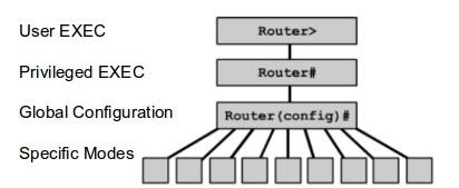
6 X.25 software, Version FastEthernet/IEEE interface(s) 32K bytes of non-volatile configuration memory K bytes of ATA CompactFlash (Read/Write) Configuration register is 0x2102 Basic Router Configuration: --- System Configuration Dialog --- Continue with configuration dialog? [yes/no]: no Press RETURN to get started! Router>enable Router#configure terminal Router(config)# When configuring a router, certain basic tasks are performed including: Naming the router Setting passwords Configuring interfaces Configuring a banner Saving changes on a router Verifying basic configuration and router operations Naming the router: Router>enable Router#configure terminal Enter configuration commands, one per line. End with CNTL/Z. Router(config)#hostname NECRouter NECRouter(config)# Setting Passwords: There are two types of passwords Enable password, that is kept to prevent users from entering privileged mode and another is console password that is used to prevent entering into the rouer console. Enable Password: NECRouter>enable NECRouter#configure terminal Enter configuration commands, one per line. End with CNTL/Z. NECRouter(config)#enable secret password Page:6
7 NECRouter(config)#exit NECRouter#exit After you exit from the privileged mode and try again to enter privileged mode by entering enable command then, it will prompt for password. NECRouter>enable Password: NECRouter# Console Password: NECRouter>enable NECRouter#configure terminal Enter configuration commands, one per line. End with CNTL/Z. NECRouter(config)#line console 0 NECRouter(config-line)#password cisco NECRouter(config-line)#login NECRouter(config-line)# When you try to enter to Router console it will ask for password. User Access Verification Password: Configuring the interfaces: There are two types of interfaces to be configured for the ip connectivity. Lan interfaces (Ethernet and Fast Ethernet and other is WAN interfaces namely serial interfaces). To list the the interfaces name issue the command show ip interface brief. Router>show ip interface brief Interface IP-Address OK? Method Status Protocol FastEthernet0/0 unassigned YES unset administratively down down FastEthernet1/0 unassigned YES unset administratively down down Serial2/0 unassigned YES unset administratively down down Serial3/0 unassigned YES unset administratively down down FastEthernet4/0 unassigned YES unset administratively down down FastEthernet5/0 unassigned YES unset administratively down down Page:7
8 or alternatively you can issue the command show protocols. Router>sh protocols Global values: Internet Protocol routing is enabled FastEthernet0/0 is administratively down, line protocol is down FastEthernet1/0 is administratively down, line protocol is down Serial2/0 is administratively down, line protocol is down Serial3/0 is administratively down, line protocol is down FastEthernet4/0 is administratively down, line protocol is down FastEthernet5/0 is administratively down, line protocol is down Setting ip address on the interfaces: LAN Interfaces: Router>enable Router#configure terminal Enter configuration commands, one per line. End with CNTL/Z. Router(config)#interface fastethernet 1/0 Router(config-if)#ip address Router(config-if)#no shutdown WAN Interfaces: Router>enable Router#configure terminal Enter configuration commands, one per line. End with CNTL/Z. Router(config)#interface serial 2/0 Router(config-if)#ip address Router(config-if)#no shutdown %LINK-5-CHANGED: Interface Serial2/0, changed state to down Router(config-if)#clock rate Router(config-if)# Note: For DCE (Data communication equipments, you only have to provide the clock rate, provide the clock rate to that end of the serial interface where the sign of clock appears in case of packet tracer). Configuring the banner: From the global configuration mode, configure the message-of-the-day (motd) banner. A delimiting character, such as a "%" is used at the beginning and at the end of the message. The delimiter allows you to configure a multiline banner, as shown here. Router(config)#banner motd % Enter TEXT message. End with the character '%'. Page:8
9 ############################################## Unauthroised access is restricted!!!!! ############################################## % Router(config)# Saving changes on the router: Everything you are configuring in the router are not saved and are lost once the router is reloaded. To save the configuration permanently into the NVRAM follow either of the following steps. Router#write Building configuration... [OK] or alternatively, Router#copy running-config startup-config Destination filename [startup-config]? Building configuration... [OK] Router# running-config: Everything in the RAM startup-config: Everything in the NVRAM Verifying basic configuration and router operations : Router1#show running-config Displays the configuration in the RAM, it must be saved into NVRAM. Router1#copy running-config startup-config Router1#show startup-config Router1#show ip route Display the routing table in the router. R1#show ip interface brief This command displays abbreviated interface configuration information, including IP address and interface status. Page:9
10 Configuring Telnet password on Router: Router1>enable Router1#configure terminal Enter configuration commands, one per line. End with CNTL/Z. Router1(config)#line vty 0 15 Router1(config-line)#password cisco Router1(config-line)#login Router1(config-line)# Now you can telnet this router though the remote accessible router or PC. Collision domain: and Broadcast domain: Collision Domain: a collision domain is the set of LAN interfaces whose frames could collide with each other, but not with frames sent by any other devices in the network. Each port of the switch acts as a collision domain, while whole HUB acts as a single collision domain. Broadcast domain:the term broadcast domain relates to where broadcasts can be forwarded. A broadcast domain encompasses a set of devices for which, when one of the devices sends a broadcast, all the other devices receive a copy of the broadcast. For example, switches flood broadcasts and multicasts on all ports. Because broadcast frames are sent out all ports, a switch creates a single broadcast domain. Routing and Routing Protocols: The primary responsibility of a router is to direct packets destined for local and remote networks by: Determining the best path to send packets Forwarding packets toward their destination The router uses its routing table to determine the best path to forward the packet. When the router receives a packet, it examines its destination IP address and searches for the best match with a network address in the router's routing table. The routing table also includes the interface to be used to forward the packet. Once a match is found, the router encapsulates the IP packet into the data link frame of the outgoing or exit interface, and the packet is then forwarded toward its destination. Static Routes: Static routes are configured manually, network administrators must add and delete static routes to reflect any network topology changes. In a large network, the manual maintenance of routing tables could require a lot of administrative time. On small networks with few possible changes, static routes require very little maintenance. Static routing is not as scalable as dynamic routing because of the extra administrative requirements. Even in large networks, static routes that are intended to accomplish a specific purpose are often configured in conjunction with a dynamic routing protocol. Page:10

11 When to use static Routing: A network consists of only a few routers. Using a dynamic routing protocol in such a case does not present any substantial benefit. On the contrary, dynamic routing may add more administrative overhead. A network is connected to the Internet only through a single ISP. There is no need to use a dynamic routing protocol across this link because the ISP represents the only exit point to the Internet. A large network is configured in a hub-and-spoke topology. A hub-and-spoke topology consists of a central location (the hub) and multiple branch locations (spokes), with each spoke having only one connection to the hub. Using dynamic routing would be unnecessary because each branch has only one path to a given destination-through the central location. Connected Routes: Those network that are directly connected to the Router are called connected routes and are not needed to configure on the router for routing. They are automatically routed by the Router. Dynamic Routes: Dynamic routing protocol uses a route that a routing protocol adjusts automatically for topology or traffic changes. Page:11

12 Routing Protocol: A routing protocol is the communication used between routers. A routing protocol allows routers to share information about networks and their proximity to each other. Routers use this information to build and maintain routing tables. Autonomous System: An AS is a collection of networks under a common administration that share a common routing strategy. To the outside world, an AS is viewed as a single entity. The AS may be run by one or more operators while it presents a consistent view of routing to the external world. The American Registry of Internet Numbers (ARIN), a service provider, or an administrator assigns a 16-bit identification number to each AS. Page:12
13 Dynamic Routing Protocol: 1. Interior Gateway protocol (IGP) I). Distance Vector Protocol II). Link State Protocol 2. Exterior Gateway Protocol (EGP) Interior gateway protocol (IGP): Within one Autonomous System. Exterior Routing Protocol(EGP):Between the Autonomous System. Example BGP (Boarder gateway protocol) Metric: There are cases when a routing protocol learns of more than one route to the same destination. To select the best path, the routing protocol must be able to evaluate and differentiate between the available paths. For this purpose a metric is used. A metric is a value used by routing protocols to assign costs to reach remote networks. The metric is used to determine which path is most preferable when there are multiple paths to the same remote network. Each routing protocol uses its own metric. For example, RIP uses hop count, EIGRP uses a combination of bandwidth and delay, and Cisco's implementation of OSPF uses bandwidth. Administrative Distance: (AD) Adminstrative distance (AD) is used to rate effectiveness and truthfulness, reliability of routing information. The lower the administrative distance,more reliable the routing protocol is. Default AD: Route Connected Routes 0 Static Route 1 EIGRP 90 Value OSPF 110 RIP 120 Unknown 255 Routing Rules: 1. If a router has two routes to a destination then routes with lower AD is used as a path. 2. If both routes has same AD, then it looks for cost or metric of the route. The route with lower cost of metric is preferred as the best route. 3. If cost or metric are also same, then it serves as load balancing in Round Robin Fashion. Page:13
14 Classless and Classful Routing Protocols Some routing protocols must consider the Class A, B, or C network number that a subnet resides in when performing some of its tasks. Other routing protocols can ignore Class A, B, and C rules altogether. Routing protocols that must consider class rules are called classful routing protocols; those that do not need to consider class rules are called classless routing protocols. Classless routing protocols and classful routing protocols are identified by the same three criteria, as summarized in Table. Feature Classless Classful Support VLSM Yes No Sends subnet mask in routing updates Yes No Supports manual route summarization Yes No Convergence The term convergence refers to the overall process that occurs with routing protocols when something changes in a network topology. When a link comes up or fails, or when a router fails or is first turned on, the possible routes in the internetwork change. The processes used by routing protocols to recognize the changes, to figure out the now-best routes to each subnet, and to change all the routers routing tables, is called convergence. Some routing protocols converge more quickly than others. As you might imagine, the capability to converge quickly is important, because in some cases, until convergence completes, users might not be able to send their packets to particular subnets. Distance Vector Routing Algorithm: As the name implies, distance vector means that routes are advertised as vectors of distance and direction. Distance is defined in terms of a metric such as hop count and direction is simply the nexthop router or exit interface. A router using a distance vector routing protocol does not have the knowledge of the entire path to a destination network. Instead the router knows only: The direction or interface in which packets should be forwarded and The distance or how far it is to the destination network. To show you more exactly what a distance vector protocol does, Figure shows a view of what a router learns with a distance vector routing protocol. The figure shows an internetwork in which R1 learns about three routes to reach subnet X: The four-hop route through R2 The three-hop route through R5 The two-hop route through R7 Page:14


15 R1 learns about the subnet, and a metric associated with that subnet, and nothing more. R1 must then pick the best route to reach subnet X. In this case, it picks the two-hop route through R7, because that route has the lowest metric. Distance vector protocols typically use the Bellman-Ford algorithm for the best path route determination. Page:15


16 Initial Update: R1 Sends an update about network out the Serial0/0/0 interface Sends an update about network out the FastEthernet0/0 interface Receives update from R2 about network with a metric of 1 Stores network in the routing table with a metric of 1 R2 Sends an update about network out the Serial 0/0/0 interface Sends an update about network out the Serial 0/0/1 interface Receives an update from R1 about network with a metric of 1 Stores network in the routing table with a metric of 1 Receives an update from R3 about network with a metric of 1 Stores network in the routing table with a metric of 1 R3 Sends an update about network out the Serial 0/0/0 interface Sends an update about network out the FastEthernet0/0 Receives an update from R2 about network with a metric of 1 Stores network in the routing table with a metric of 1 After this first round of update exchanges, each router knows about the connected networks of their directly connected neighbors. However, did you notice that R1 does not yet know about and that R3 does not yet know about ? Full knowledge and a converged network will not take place until there is another exchange of routing information. Page:16

17 Next Update: R1 Sends an update about network out the Serial 0/0/0 interface. Sends an update about networks and out the FastEthernet0/0 interface. Receives an update from R2 about network with a metric of 2. Stores network in the routing table with a metric of 2. Same update from R2 contains information about network with a metric of 1. There is no change; therefore, the routing information remains the same. R2 Sends an update about networks and out of Serial 0/0/0 interface. Sends an update about networks and out of Serial 0/0/1 interface. Receives an update from R1 about network There is no change; therefore, the routing information remains the same. Receives an update from R3 about network There is no change; therefore, the routing information remains the same. R3 Sends an update about network out the Serial 0/0/0 interface. Sends an update about networks and out the FastEthernet0/0 interface. Receives an update from R2 about network with a metric of 2. Stores network in the routing table with a metric of 2. Same update from R2 contains information about network with a metric of 1. There is no change; therefore, the routing information remains the same. Note: Distance vector routing protocols typically implement a technique known as split horizon. Split horizon prevents information from being sent out the same interface from which it was received. For example, R2 would not send an update out Serial 0/0/0 containing the network because R2 learned about that network through Serial 0/0/0. Link State Routing Algorithm: Also known as Shortest path Routing algorithm. Link states: Information about the state of (Router interfaces) links is known as link-states. As you can see in the figure, this information includes: The interface's IP address and subnet mask. Page:17
18 The type of network, such as Ethernet (broadcast) or Serial point-to-point link. The cost of that link. Any neighbor routers on that link. Dijkstra's Shortest Path first algorithm So exactly how does a link-state routing protocol work? All routers will complete the following generic link-state routing process to reach a state of convergence: 1. Each router learns about its own links, its own directly connected networks. This is done by detecting that an interface is in the up state. 2. Each router is responsible for meeting its neighbors on directly connected networks. link state routers do this by exchanging Hello packets with other link-state routers on directly connected networks. 3. Each router builds a Link-State Packet (LSP) containing the state of each directly connected link. This is done by recording all the pertinent information about each neighbor, including neighbor ID, link type, and bandwidth. 4. Each router floods the LSP to all neighbors, who then store all LSPs received in a database. Neighbors then flood the LSPs to their neighbors until all routers in the area have received the LSPs. Each router stores a copy of each LSP received from its neighbors in a local database. Page:18
19 5. Each router uses the database to construct a complete map of the topology and computes the best path to each destination network. Like having a road map, the router now has a complete map of all destinations in the topology and the routes to reach them. The SPF algorithm is used to construct the map of the topology and to determine the best path to each network. Advantages of Link state Routing protocol: Build the topological map: Link-state routing protocols create a topological map, or SPF tree of the network topology. Distance vector routing protocols do not have a topological map of the network. Faster Convergence: When receiving a Link-state Packet (LSP), link-state routing protocols immediately flood the LSP out all interfaces except for the interface from which the LSP was received. This way, it achieve the faster convergence. With distance vector routing algorithm, router needs to process each routing update and update its routing table before flooding them out other interfaces. Event Driven Updates: After the initial flooding of LSPs, link-state routing protocols only send out an LSP when there is a change in the topology. The LSP contains only the information regarding the affected link. Unlike some distance vector routing protocols, link-state routing protocols do not send periodic updates. Distance vector vs. Link state: Sno. Distance Vector Link State 1 Uses hop count as Metric. Uses shortest path. 2 View the network from the perspective of neighbor. Gets common view of entire network topology. 3 Has frequent and periodic updates Has event triggered updates. 4 Slow convergence Faster convergence 5 Susceptible to routing loops. Not as susceptible to routing loops. 6 Easy to configure and administer. Difficult to configure and administer. 7 Requires less memory and processing power of routers. Requires more precessing power and memory than distance vector. 8 Consumes a lot of Bandwidth. Consumes less BW than distance vector. 9 Passes copies of routing table to neighbor routers. Passes link-state routing updates to other routers. Page:19
#ip route network-address subnet-mask {ip-address exit-interface } The following parameters are used: network-address - Destination network address of")
20 10 Eg. RIP Eg. OSPF Static Route Configuration: Router(config)#ip route network-address subnet-mask {ip-address exit-interface } The following parameters are used: network-address - Destination network address of the remote network to be added to the routing table subnet-mask - Subnet mask of the remote network to be added to the routing table. The subnet mask can be modified to summarize a group of networks. One or both of the following parameters must also be used: ip-address - Commonly referred to as the next-hop router's IP address exit-interface - Outgoing interface that would be used in forwarding packets to the destination network Page:20
21 Example: R1#conf t R1(config)#ip route Let's examine each element in this output: ip route - Static route command Network address of remote network Subnet mask of remote network Serial 0/0/0 interface IP address on R2, which is the "next-hop" to this network Similarly you can configure for other subnetwork and routers. Verifying static Route: show ip route ping Summarizing Routes to Reduce the Size of the Routing Table Creating smaller routing tables makes the routing table lookup process more efficient, because there are fewer routes to search. If one static route can be used instead of multiple static routes, the size of the routing table will be reduced. In many cases, a single static route can be used to represent dozens, hundreds, or even thousands of routes. We can use a single network address to represent multiple subnets. For example, the networks /16, /16, /16, /16, /16, /16, all the way through /16 can be represented by a single network address: /8. Route Summarization Multiple static routes can be summarized into a single static route if: 1. The destination networks can be summarized into a single network address, and 2. The multiple static routes all use the same exit-interface or next-hop IP address. This is called route summarization. Page:21
22 In our example, R3 has three static routes. All three routes are forwarding traffic out the same Serial0/0/1 interface. The three static routes on R3 are: ip route Serial0/0/1 ip route Serial0/0/1 ip route Serial0/0/1 If possible, we would like to summarize all of these routes into a single static route /24, /24 and /24 can be summarized to the /22 network. Because all three routes use the same exit interface, they can be summarized to the single network, and we can create a single summary route. To implement the summary route, we must first delete the three current static routes: R3(config)#no ip route serial0/0/1 R3(config)#no ip route serial0/0/1 R3(config)#no ip route serial0/0/1 Next, we will configure the summary static route: R3(config)#ip route serial0/0/1 Page:22
23 Default Static Route: The default static route matches all packets.a default static route is a route that will match all packets. Default static routes are used: When no other routes in the routing table match the packet's destination IP address. In other words, when a more specific match does not exist. A common use is when connecting a company's edge router to the ISP network. When a router has only one other router to which it is connected. This condition is known as a stub router. Configuring a Default Static Route The syntax for a default static route is similar to any other static route, except that the network address is and the subnet mask is : Router(config)#ip route [exit-interface ip-address ] R1(config)#ip route serial 0/0/0 Default routes are very common on routers. Instead of routers having to store routes for all of the networks in the Internet, they can store a single default route to represent any network that is not in the routing table. Page:23
24 Routing Information Protocol (RIP): RIP is a true distance vector routing protocol. RIP uses hop count as its only metric for path selection. Advertised routes with hop counts greater than 15 are unreachable. Messages are broadcast every 30 seconds. RIP works well in small networks, but it s inefficient on large networks with slow WAN links or on networks with a large number of routers installed. RIP version 1 uses only classful routing, which means that all devices in the network must use the same subnet mask. This is because RIP version 1 doesn t send updates with subnet mask information in tow. RIP version 2 provides something called prefix routing and does send subnet mask information with the route updates. This is called classless routing. Rip configuration: To enter the router configuration mode for RIP, enter router rip at the global configuration prompt. R1(config)#router rip R1(config-router)# This command does not directly start the RIP process. Instead, it provides access to configure routing protocol settings. No routing updates are sent. If you need to completely remove the RIP routing process from a device, negate the command with no router rip. This command stops the RIP process and erases all existing RIP configurations. Page:24
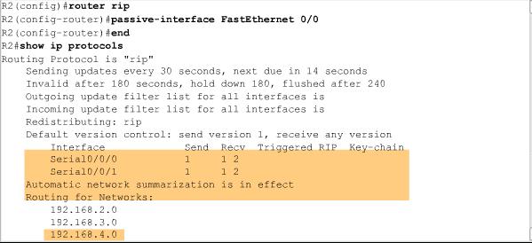
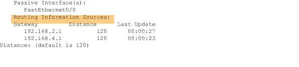
25 By entering the RIP router configuration mode, the router is instructed to run RIP. But the router still needs to know which local interfaces it should use for communication with other routers, as well as which locally connected networks it should advertise to those routers. To enable RIP routing for a network, use the network command in the router configuration mode and enter the classful network address for each directly connected network. Router(config-router)#network <directly-connected-classful-network-address> Note: If you enter a subnet address, the IOS automatically converts it to a classful network address. For example, if you enter the command network , the router will convert it to network Example: R1(config)#router rip R1(config-router)#network R1(config-router)#network similarly, you can write for R2 and R3. Verifying and Troubleshooting RIP: 1. show ip protocols 2. debup ip rip 3. to stop debug command, use the command undebug all 4. show ip route Passive Interface: the passive-interface command, prevents the transmission of routing updates through a router interface but still allows that network to be advertised to other routers. Enter the passive-interface command in router configuration mode. Router(config-router)#passive-interface <interface-name> This command stops routing updates out the specified interface. However, the network that the specified interface belongs to will still be advertised in routing updates that are sent out other interfaces. In the figure, R2 is first configured with the passive-interface command to prevent routing updates on FastEthernet0/0 because no RIP neighbors exist on the LAN. The show ip protocols command is then used to verify the passive interface. Notice that the interface is no longer listed under Interface, but under a new section called Passive Interface(s). Also notice that the network is still listed under Routing for Networks, which means that this network is still included as a route entry in RIP updates that are sent to R1 and R3. Page:25
26 Automatic Summarization: Page:26
27 Page:27
28 RIP is a classful routing protocol that automatically summarizes classful networks across major network boundaries. In the figure, you can see that R2 has interfaces in more than one major classful network. This makes R2 a boundary router in RIP. Serial 0/0/0 and FastEthernet 0/0 interfaces on R2 are both inside the boundary. The Serial 0/0/1 interface is inside the boundary. Page:28

29 Because boundary routers summarize RIP subnets from one major network to the other, updates for the , and networks will automatically be summarized into when sent out R2's Serial 0/0/1 interface. Advantages of automatic summarization: Smaller routing updates sent and received, which uses less bandwidth for routing updates between R2 and R3. R3 has a single route for the /16 network, regardless of how many subnets there are or how it is subnetted. Using a single route results in a faster lookup process in the routing table for R3. Disadvantages of automatic summarization: Dis-contiguous network don't converge with RIP Version1. Page:29
30 RIP version 2: Rip version1 Limitations: RIPv1 doesn't support VLSM. To enable RIP version 2 just write this router configuration command. Router(config)# router rip Router(config-router)#version 2 Dis-contiguous network is also not converged with RIPv2. You have to disable the autosummary feature of RIP. By the command no auto-summary command. Router(config)# router rip Router(config-router# no auto-summary RIPv1 VS RIPv2 Page:30

31 Propagating the default route in RIPv1: To provide Internet connectivity to all other networks in the RIP routing domain, the default static route needs to be advertised to all other routers that use the dynamic routing protocol. You could configure a static default route on R1 pointing to R2, but this technique is not scalable. With every router added to the RIP routing domain, you would have to configure another static default route. Why not let the routing protocol do the work for you? R2(config)# router rip R2(config-router)# default-information originate In many routing protocols, including RIP, you can use the default-information originate command in Page:31
32 router configuration mode to specify that this router is to originate default information, by propagating the static default route in RIP updates. In the figure, R2 has been configured with the defaultinformation originate command. Notice from the debug ip rip output that it is now sending a "quadzero" static default route to R1. Page:32
Building the Routing Table. Introducing the Routing Table Directly Connected Networks Static Routing Dynamic Routing Routing Table Principles
 Building the Routing Table Introducing the Routing Table Directly Connected Networks Static Routing Dynamic Routing Routing Table Principles Introducing the Routing Table R1# show ip route Codes: C - connected,
Chapter 5 RIP version 1
 Cisco CCNA 2 Exploration - Routing Chapter 5 RIP version 1 João José jjose@ualg.pt http://w3.ualg.pt/~jjose/cisco/ Based on: Graziani, R. (2008) CIS 82 Routing Theory and Concepts RIPv1: A Distance Vector,
SEMESTER 2 Chapter 1 Planning and Cabling a Network V 4.0
 SEMESTER 2 Chapter 1 Planning and Cabling a Network V 4.0 135 points 1.1.1 What are the common components between a router and other computers? CPU RAM ROM Operating System 1.1.1.2 What does a router connect?
Lab 2.8.1: Basic Static Route Configuration
 Topology Diagram Addressing Table Device Interface IP Address Subnet Mask Default Gateway R1 Fa0/0 172.16.3.1 255.255.255.0 N/A S0/0/0 172.16.2.1 255.255.255.0 N/A Fa0/0 172.16.1.1 255.255.255.0 N/A R2
CCNA EXPLORATION V4.0 ROUTING PROTOCOLS AND CONCEPTS ACCESSIBLE INSTRUCTOR MATERIALS POWERPOINT OBJECTIVES
 CCNA EXPLORATION V4.0 ROUTING PROTOCOLS AND CONCEPTS ACCESSIBLE INSTRUCTOR MATERIALS Prepared by Cisco Learning Institute June 23, 2008 Chapter 1 Introduction to Routing and Packet Forwarding Objectives
TELECOMMUNICATION MANAGEMENT AND NETWORKS
 QUAID-E-AWAM UNIVERSITY OF ENGINEERING SCIENCE AND TECHNOLOGY, NAWABSHAH TELECOMMUNICATION MANAGEMENT AND NETWORKS LAB # 3 CONFIGURING INTERFACES OF ROUTER AND SWITCH Topology Diagram Addressing Table
Chapter 7: Routing Dynamically. Routing & Switching
 Chapter 7: Routing Dynamically Routing & Switching The Evolution of Dynamic Routing Protocols Dynamic routing protocols used in networks since the late 1980s Newer versions support the communication based
KIM DONNERBORG / RTS. Cisco Lab Øvelse Af Kim Donnerborg / RTS. Side 0 af 8
 KIM DONNERBORG / RTS Side 0 af 8 INDHOLDSFORTEGNELSE Lab: Basic Router Configuration... 2 Topology Diagram... 2 Addressing Table... 2 Learning Objectives... 2 Scenario... 2 Task 1: Cable the Network....
Final exam study Guide
 Final exam study Guide K-1A * In relationship to the OSI layer model and encapsulation/decapsulation process, what happen to a packet that travels through multiple hops of routers? - What happen to the
TDC 363 Introduction to LANs
 TDC 363 Introduction to LANs Routing Protocols and RIP Greg Brewster DePaul University TDC 363 1 Dynamic Routing Routing Protocols Distance Vector vs. Link State Protocols RIPv1 & RIPv2 RIP Problems Slow
9.1. Routing Protocols
 9.1. Routing Protocols Each organization that has been assigned a network address from an ISP is considered an autonomous system (AS). That organization is free to create one large network, or divide the
Lab Correcting RIPv2 Routing Problems
 Lab 9.4.2 Correcting RIPv2 Routing Problems e Interface IP Address Subnet Mask Default Gateway Device Host Name Interface IP Address Subnet Mask Default Gateway R1 BRANCH1 Fast Ethernet 0/0 172.16.0.1
Introduction to Local and Wide Area Networks
 Introduction to Local and Wide Area Networks Lecturers Amnach Khawne Jirasak Sittigorn Chapter 1 1 Routing Protocols and Concepts Chapter 4 : Distance Vector Routing Protocols Chapter 5 : RIP version 1
Lab 9.6.1: Basic EIGRP Configuration Lab
 Lab 9.6.1: Basic EIGRP Configuration Lab Topology Diagram Address Table 1 Learning Objectives Upon completion of this lab, you will be able to: Cable a network according to the Topology Diagram. Erase
Smart Serial. Show interfaces. Shut down. logging synchronous
 SEMESTER 2 Chapter 2 Static Networking V 4.0 2.1.1 What are the primary responsibilities of the router? 2.1.3 What is the first serial connector described called at the router end? What is the first serial
Chapter 5. RIP Version 1 (RIPv1) CCNA2-1 Chapter 5
 CCNA2-1 Chapter 5") Chapter 5 RIP Version 1 (RIPv1) CCNA2-1 Chapter 5 RIP Version 1 RIPv1: Distance Vector, Classful Routing Protocol CCNA2-2 Chapter 5 Background and Perspective RIP evolved from the Xerox Network System
Chapter 5 RIP Version 1 (RIPv1) CCNA2-1 Chapter 5 RIP Version 1 RIPv1: Distance Vector, Classful Routing Protocol CCNA2-2 Chapter 5 Background and Perspective RIP evolved from the Xerox Network System
Lab10- Configuring EIGRP
 Lab10- Configuring EIGRP Topology Lab10- Configuring EIGRP Page 1 Learning Objectives Upon completion of this lab, you will be able to: Cable a network according to the Topology Diagram. Erase the startup
RIP version 1. Routing Protocols and Concepts Chapter 5. Version Cisco Systems, Inc. All rights reserved. Cisco Public 1
 RIP version 1 Routing Protocols and Concepts Chapter 5 Version 4.0 1 Objectives Describe the functions, characteristics, and operation of the RIPv1 protocol. Configure a device for using RIPv1. Verify
CCNA IP ROUTING. Revision no.: PPT/2K605/03
 CCNA 640-801 IP ROUTING Revision no.: PPT/2K605/03 Routing Basics The term routing is used for taking a packet from one device and sending it through the network to another device on a different network.
Chapter 7 Routing Protocols
 Chapter 7 Routing Protocols Nonroutable Protocols In the early days of networking, networks were small collections of computers linked together For the purposes of sharing information and expensive peripherals
Lab 4: Routing using OSPF
 Network Topology:- Lab 4: Routing using OSPF Device Interface IP Address Subnet Mask Gateway/Clock Description Rate Fa 0/0 172.16.1.17 255.255.255.240 ----- R1 LAN R1 Se 0/0/0 192.168.10.1 255.255.255.252
CHAPTER 4: ROUTING DYNAMIC. Routing & Switching
 CHAPTER 4: ROUTING DYNAMIC Routing & Switching CHAPTER4 4.1 Dynamic Routing Protocols 4.2 Distance Vector Dynamic Routing 4.3 RIP and RIPng Routing 4.4 Link-State Dynamic Routing 4.5 The Routing Table
Antonio Cianfrani. Routing Protocols
 Antonio Cianfrani Routing Protocols Routing protocols A routing protocol provides a communication channel among routers to exchange reachability information about networks Routing tables are properly configured
Introduction To Cisco IOS
 S SRS CNS Lab2 IntroductionToCiscoIOS IntroductionToCiscoIOS 1 RouterArchitecture Ciscoroutershavemanysimilaritieswithpersonalcomputers.Afterall,mostoperating systems offer basic routing features to any
Module 9, Assignment 7
 Module 9, Assignment 7 7.2.3 Control Router via Console (in Packet Tracer) 1. Prepare a Cisco 1841 Router (see figure 6-9). 2. Prepare a PC for administration. 3. Prepare a console cable and plug the serial
Lab: Basic Static Route Configuration
 Lab: Basic Static Route onfiguration Topology Diagram Addressing Table Device Interface IP Address Subnet Mask Default Gateway R1 Fa0/0 172.16.3.1 255.255.255.0 N/A S0/0/0 172.16.2.1 255.255.255.0 N/A
Chapter 6: Network Layer
 Chapter 6: Network Layer Introduction to Networks Intro to Networks v5 Network Layer Intro to Networks v5 2 The Network Layer End to End Transport processes Addressing end devices Encapsulation of Packets
Top-Down Network Design, Ch. 7: Selecting Switching and Routing Protocols. Top-Down Network Design. Selecting Switching and Routing Protocols
 Top-Down Network Design Chapter Seven Selecting Switching and Routing Protocols Copyright 2010 Cisco Press & Priscilla Oppenheimer 1 Switching 2 Page 1 Objectives MAC address table Describe the features
Chapter 3. Introduction to Dynamic Routing Protocols. CCNA2-1 Chapter 3
 Chapter 3 Introduction to Dynamic Routing Protocols CCNA2-1 Chapter 3 Introduction to Dynamic Routing Protocols Introduction to Dynamic Routing Protocols CCNA2-2 Chapter 3 Perspective and Background Dynamic
CCNA 3 (v v6.0) Chapter 5 Exam Answers % Full
 Chapter 5 Exam Answers % Full") CCNA 3 (v5.0.3 + v6.0) Chapter 5 Exam Answers 2017 100% Full ccnav6.com /ccna-3-v5-0-3-v6-0-chapter-5-exam-answers-2017-100-full.html CCNA Exam Answers 2017 CCNA 3 (v5.0.3 + v6.0) Chapter 5 Exam Answers
CCNA 3 (v5.0.3 + v6.0) Chapter 5 Exam Answers 2017 100% Full ccnav6.com /ccna-3-v5-0-3-v6-0-chapter-5-exam-answers-2017-100-full.html CCNA Exam Answers 2017 CCNA 3 (v5.0.3 + v6.0) Chapter 5 Exam Answers
Lab 9.6.2: Challenge EIGRP Configuration Lab
 Topology Diagram Addressing Table Device Interface IP Address Subnet Mask Default Gateway HQ BRANCH1 BRANCH2 PC1 PC2 PC3 Fa0/0 S0/0/0 S0/0/1 Lo1 Fa0/0 S0/0/0 S0/0/1 Fa0/0 S0/0/0 S0/0/1 NIC NIC NIC All
Lab Configuring OSPF Timers 2500 Series
 Lab 2.3.5 Configuring OSPF Timers 2500 Series Objective Setup an IP addressing scheme for OSPF area. Configure and verify OSPF routing. Modify OSPF interface timers to adjust efficiency of network. Background/Preparation
Lab : Challenge OSPF Configuration Lab. Topology Diagram. Addressing Table. Default Gateway. Device Interface IP Address Subnet Mask
 Topology Diagram Addressing Table Device Interface IP Address Subnet Mask Default Gateway Fa0/0 HQ S0/0/0 S0/0/1 Lo1 10.10.10.1 255.255.255.252 Fa0/0 Branch1 S0/0/0 S0/0/1 Fa0/0 Branch2 S0/0/0 S0/0/1 PC1
Draft Manuscript Draft M. Manuscript Draft Ma. t Manuscript Draft Manu. ipt Draft Manuscript Dra. anuscript Draft Manuscri
 M aft Ma CHAPTER 5 ript Dra RIP Version 1 Objectives aft Ma Upon completion of this chapter, you should be able to answer the following questions: What are the functions, characteristics, and operation
RIPv2. Routing Protocols and Concepts Chapter 7. ITE PC v4.0 Chapter Cisco Systems, Inc. All rights reserved. Cisco Public
 RIPv2 Routing Protocols and Concepts Chapter 7 1 Objectives Encounter and describe the limitations of RIPv1 s limitations. Apply the basic Routing Information Protocol Version 2 (RIPv2) configuration commands
Planning for Information Network
 Planning for Information Network Lecture 8: Network Routing Protocols Assistant Teacher Samraa Adnan Al-Asadi 1 Routing protocol features There are many ways to characterize routing protocols, including
Chapter 5. RIP Version 1 (RIPv1)
") Chapter 5 RIP Version 1 (RIPv1) CCNA2-1 Chapter 5 Note for Instructors These presentations are the result of a collaboration among the instructors at St. Clair College in Windsor, Ontario. Thanks must
Chapter 5 RIP Version 1 (RIPv1) CCNA2-1 Chapter 5 Note for Instructors These presentations are the result of a collaboration among the instructors at St. Clair College in Windsor, Ontario. Thanks must
Antonio Cianfrani. Packet Tracer
 Antonio Cianfrani Packet Tracer Packet Tracer (1/2) Packet Tracer? Cisco Packet Tracer is a software able to emulate CISCO networking devices. Packet Tracer features: Allows to create network topologies
2008 NDP Lectures 7 th Semester
 2008 NDP Lectures 7 th Semester Neeli R. Prasad, Associate Professor Head of Wireless Security and Sensor Networks Group Networking and Security Aalborg University Niels Jernes Vej 12, 9220 Aalborg East,
Two types of routing protocols are used in internetworks: interior gateway protocols (IGPs) and exterior gateway protocols (EGPs).
 and exterior gateway protocols (EGPs).") Introduction Dynamic routing is when protocols are used to find networks and update routing tables on routers. True, this is easier than using static or default routing, but it ll cost you in terms of
Introduction Dynamic routing is when protocols are used to find networks and update routing tables on routers. True, this is easier than using static or default routing, but it ll cost you in terms of
CCNA Questions/Answers Routing Protocols
 Refer to the exhibit and configuration shown above. Routers R1 and R2 are properly configured with eigrp 976 protocol and are able to ping interfaces fa0/1 and fa0/2, respectively. Which commands are necessary
This document is exclusive property of Cisco Systems, Inc. Permission is granted to print and copy this document for non-commercial distribution and
 This document is exclusive property of Cisco Systems, Inc. Permission is granted to print and copy this document for non-commercial distribution and exclusive use by instructors in the CCNA Exploration:
8. Refer to the exhibit. The ORL router is unable to form a neighbor relationship with the JAX router. What is a possible cause of this problem?
 1. Refer to the exhibit. A new PC was deployed in the Sales network. It was given the host address of 192.168.10.31 with a default gateway of 192.168.10.17. The PC is not communicating with the network
Lab Configuring Basic RIPv2 (Solution)
") (Solution) Topology 2017 Cisco and/or its affiliates. All rights reserved. This document is Cisco Public. Page 1 of 15 Addressing Table Objectives Device Interface IP Address Subnet Mask Default Gateway
(Solution) Topology 2017 Cisco and/or its affiliates. All rights reserved. This document is Cisco Public. Page 1 of 15 Addressing Table Objectives Device Interface IP Address Subnet Mask Default Gateway
Introduction to Routing and Packet Forwarding
 Introduction to Routing and Packet Forwarding Routing Protocols and Concepts 1 Objectives Identify a router as a computer with an OS and hardware designed for the routing process. Demonstrate the ability
Default & Static Routes and Routing Information Protocol. Presented by : Mohammed Hamad
 Default & Static Routes and Routing Information Protocol Presented by : Mohammed Hamad When a device has multiple paths to reach a destination, it always selects one path by preferring it over others.
Unit 3: Dynamic Routing
 Unit 3: Dynamic Routing Basic Routing The term routing refers to taking a packet from one device and sending it through the network to another device on a different network. Routers don t really care about
ord Recovery Procedure for the Cisco Catalyst 8510 Multiserv
 ord Recovery Procedure for the Cisco Catalyst 8510 Multiserv Table of Contents Password Recovery Procedure for the Cisco Catalyst 8510 Multiservice Switch Router...1 Introduction...1 Before You Begin...1
SEMESTER 2 Chapter 3 Introduction to Dynamic Routing Protocols V 4.0
 SEMESTER 2 Chapter 3 Introduction to Dynamic Routing Protocols V 4.0 3.1.1 What are the four routing RIP, RIPv2, EIGRP, OSPFv2 protocols that are the focus of this course? 3.1.1.2 What are routing protocols?
TDC 363 Introduction to LANs
 TDC 363 Introduction to LANs OSPF Greg Brewster DePaul University TDC 363 Greg Brewster, DePaul University 1 OSPF Link State Routing Algorithms Open Shortest Path First (OSPF) Message Types Operations
Lab 5.6.2: Challenge RIP Configuration
 Topology Diagram Addressing Table Device Interface IP Address Subnet Mask Default Gateway BRANCH HQ ISP PC1 PC2 PC3 Fa0/0 S0/0/0 Fa0/0 S0/0/0 S0/0/1 Fa0/0 S0/0/1 NIC NIC NIC Learning Objectives Upon completion
REDDIG II Computer Networking Training
 REDDIG II Computer Networking Training JM SANCHEZ / PH RASSAT -20/06/2012 Invierno 2011 Capacitacion en fabrica - CORPAC Dynamic Routing Dynamic Routing Function(s) of Dynamic Routing Protocols: Dynamically
EIGRP. Routing Protocols and Concepts Chapter 9. Video Frank Schneemann, MS EdTech
 Video Frank Schneemann, MS EdTech EIGRP Routing Protocols and Concepts Chapter 9 ITE PC v4.0 Chapter 1 2007 Cisco Systems, Inc. All rights reserved. Cisco Public 1 9.0.1 Introduction Enhanced Interior
Top-Down Network Design
 Top-Down Network Design Chapter Seven Selecting Switching and Routing Protocols Original slides by Cisco Press & Priscilla Oppenheimer Selection Criteria for Switching and Routing Protocols Network traffic
IP Routing Tecnologie e Protocolli per Internet II rev 1
 IP Routing Tecnologie e Protocolli per Internet II rev 1 Andrea Detti Electronic Engineering dept. E-mail: andrea.detti@uniroma2.it Some sources: Cisco CCNA Routing and Switching ICND1 and ICND2 Slide
CCNA Semester 2 labs. Labs for chapters 2 10
 CCNA Semester 2 labs Labs for chapters 2 10 2.2.2.5 Lab - Configuring IPv4 Static and Default Routes 2.3.2.4 Lab - Troubleshooting Static Routes 3.2.1.9 Lab - Configuring Basic RIPv2 5.2.2.9 Lab - Configuring
The most simple way to accelerate a Router is at 9.8 m/sec/sec.
 Routing Introduction Direct vs. Indirect Delivery Static vs. Dynamic Routing Distance Vector vs. Link State (C) Herbert Haas 2005/03/11 The most simple way to accelerate a Router is at 9.8 m/sec/sec. Seen
Claim desired outcome
 Assessment Authoring - Table of Specification (TOS) The Table of Specification (TOS) is a high-level design template for a given assessment. It identifies the claims, components skills, targeted number
Chapter 4: VLSM and Classless Inter Domain Routing. ITE PC v4.0 Chapter Cisco Systems, Inc. All rights reserved.
 Chapter 4: VLSM and Classless Inter Domain Routing 1 What will we Learn from chapter 4? Compare and contrast classful and classless IP addressing. Review VLSM and explain the benefits of classless IP addressing.
(ii) Simei(config)#line console 0 Simei(config-line)#password Networking Simei(config-line)#exit
 Simei(config)#line console 0 Simei(config-line)#password Networking Simei(config-line)#exit") Sep 2008 Section A 1. Any of the following 2: a. Frame relay b. ISDN c. PPP d. HDLC 2. (i) RAM copy running-config startup-config 3. hardware platform, feature set, file format, version 4. (i) Cisco Discovery
Sep 2008 Section A 1. Any of the following 2: a. Frame relay b. ISDN c. PPP d. HDLC 2. (i) RAM copy running-config startup-config 3. hardware platform, feature set, file format, version 4. (i) Cisco Discovery
co Password Recovery Procedure for the Cisco 1700 Series R
 co Password Recovery Procedure for the Cisco 1700 Series R Table of Contents Password Recovery Procedure for the Cisco 1700 Series Routers...1 Introduction...1 Before You Begin...2 Conventions...2 Prerequisites...2
A study of WAN design, routing protocols and connectivity between Head office to Branch office
 A study of WAN design, routing protocols and connectivity between Head office to Branch office Dr. Anil Kumar Singh ABSTRACT Jagran Institute of Management, 620-W Block Saket Nagar, Kanpur 3.LAB SETUP
6.5.1: Packet Tracer Skills Integration Challenge Activity Topology Diagram
 6.5.1: Packet Tracer Skills Integration Challenge Activity Topology Diagram All contents are Copyright 1992 2007 Cisco Systems, Inc. All rights reserved. This document is Cisco Public Information. Page
CCNA EXPLORATION V4.0 ROUTING PROTOCOLS AND CONCEPTS
 CCNA EXPLORATION V4.0 ACCESSIBLE INSTRUCTOR MATERIALS COMPARISON OF NEW CURRICULA WITH EXISTING CURRICULA Prepared by Cisco Learning Institute June 23, 2008 Routing Protocols and Concepts Summary New CCNA
Basic Idea. Routing. Example. Routing by the Network
 Basic Idea Routing Routing table at each router/gateway When IP packet comes, destination address checked with routing table to find next hop address Questions: Route by host or by network? Routing table:
Cisco IOS Configuration Basics
 Cisco IOS Configuration Basics Switching Router Overview Router configuration controls the operation of the router s: Interface IP address and netmask Routing information (static, dynamic or default) Boot
Routing by the Network
 Routing Basic Idea Routing table at each router/gateway When IP packet comes, destination address checked with routing table to find next hop address Questions: Route by host or by network? Routing table:
Part II. Chapter 3. Determining IP Routes
 Part II Chapter 3 Routers perform two main functions: switching and routing. The switching function is the process of moving packets from an inbound interface to an outbound interface. The switching function
Static Routing. Routing Protocols and Concepts Chapter 2. ITE PC v4.0 Chapter Cisco Systems, Inc. All rights reserved.
 Static Routing Routing Protocols and Concepts Chapter 2 1 Objectives Define the general role a router plays in networks. Describe the directly connected networks, different router interfaces Examine directly
shortcut Tap into learning NOW! Visit for a complete list of Short Cuts. Your Short Cut to Knowledge
 shortcut Your Short Cut to Knowledge The following is an excerpt from a Short Cut published by one of the Pearson Education imprints. Short Cuts are short, concise, PDF documents designed specifically
Lab Configuring OSPF Authentication 2500 Series
 Lab 2.3.4 Configuring OSPF Authentication 2500 Series Objective Setup an IP addressing scheme for Open Shortest Path First (OSPF) area. Configure and verify OSPF routing. Introduce OSPF authentication
Lab Configuring IGRP Instructor Version 2500
 Lab 7.3.5 Configuring IGRP Instructor Version 2500 Objective Setup IP an addressing scheme using class C networks. Configure IGRP on routers. Background/Preparation Cable a network similar to the one in
Lecture (03) RIP. By: Dr. Ahmed ElShafee. Dr. Ahmed ElShafee, ACU : Fall 2016, Practical App. Networks II
 RIP. By: Dr. Ahmed ElShafee. Dr. Ahmed ElShafee, ACU : Fall 2016, Practical App. Networks II") Lecture (03) RIP By: Dr. Ahmed ElShafee ١ Dr. Ahmed ElShafee, ACU : Fall 2016, Practical App. Networks II Dynamic Routing Protocol Overview Routing protocols are used between routers to determine paths
Lecture (03) RIP By: Dr. Ahmed ElShafee ١ Dr. Ahmed ElShafee, ACU : Fall 2016, Practical App. Networks II Dynamic Routing Protocol Overview Routing protocols are used between routers to determine paths
Routing Dynamically. 3.0 Routing Dynamically. Chapter Introduction Class Activity How Much Does This Cost?
 Chapter 3 Routing Dynamically 3.0 Routing Dynamically 3.0.1.1 Introduction The data networks that we use in our everyday lives to learn, play, and work range from small, local networks to large, global
This document is exclusive property of Cisco Systems, Inc. Permission is granted to print and copy this document for non-commercial distribution and
 This document is exclusive property of Cisco Systems, Inc. Permission is granted to print and copy this document for non-commercial distribution and exclusive use by instructors in the CCNA Exploration:
LAB MANUAL for Computer Network
 LAB MANUAL for Computer Network CSE-310 F Computer Network Lab L T P - - 3 Class Work : 25 Marks Exam : 25 MARKS Total : 50 Marks This course provides students with hands on training regarding the design,
Lab Troubleshooting Routing Issues with debug Instructor Version 2500
 Lab 9.3.7 Troubleshooting Routing Issues with debug Instructor Version 2500 Objective Utilize a systematic OSI troubleshooting process to diagnose routing problems. Use various show commands to gather
Lab 2.8.2: Challenge Static Route Configuration
 Topology Diagram Addressing Table Device Interface IP Address Subnet Mask Default Gateway BRANCH HQ ISP PC1 PC2 Web Server Fa0/0 S0/0/0 Fa0/0 S0/0/0 S0/0/1 209.165.201.2 255.255.255.252 Fa0/0 209.165.200.225
Password Recovery Procedure for the Cisco 1700 and 1800 Series Routers
 Password Recovery Procedure for the Cisco 1700 and 1800 Series Routers Document ID: 22187 Introduction Prerequisites Requirements Components Used Related Products Conventions Step by Step Procedure Example
Chapter 4 Lab 4-1, Redistribution Between RIP and OSPF
 hapter 4 Lab 4-1, Redistribution Between RIP and OSPF Topology Objectives Review configuration and verification of RIP and OSPF. onfigure passive interfaces in both RIP and OSPF. Filter routing updates
Distance Vector Routing Protocols
 Distance Vector Routing Protocols Routing Protocols and Concepts Chapter 4 Version 4.0 1 Objectives Identify the characteristics of distance vector routing protocols. Describe the network discovery process
CISCO SYSTEM ADMINISTRATION (41)
") CISCO SYSTEM ADMININSTRATION PAGE 1 OF 11 CONTESTANT ID# Time Rank CISCO SYSTEM ADMINISTRATION (41) Regional 2012 TOTAL POINTS (500) Failure to adhere to any of the following rules will result in disqualification:
CISCO SYSTEM ADMININSTRATION PAGE 1 OF 11 CONTESTANT ID# Time Rank CISCO SYSTEM ADMINISTRATION (41) Regional 2012 TOTAL POINTS (500) Failure to adhere to any of the following rules will result in disqualification:
Ch6 Packet Tracer Skills Integration Challenge Topology Diagram
 Topology Diagram All contents are Copyright 1992 2007 Cisco Systems, Inc. All rights reserved. This document is Cisco Public Information. Page 1 of 7 Addressing Table for R1 Device Interface IP Address
EIGRP 04/01/2008. Routing Protocols and Concepts Chapter 9 Modified by Tony Chen
 EIGRP Routing Protocols and Concepts Chapter 9 Modified by Tony Chen 04/01/2008 1 Introduction 2 EIGRP Roots of EIGRP: IGRP -Developed in 1985 to overcome RIPv1 s limited hop count -Distance vector routing
Lab 5: Inter-VLANs Routing
 Lab 5: Inter-VLANs Routing Network Topology:- Device Interface IP Address Subnet Mask Gateway/Clock Rate Fa 0/0.10 10.5.0.1 255.255.255.192 ----- R1 Fa 0/0.20 10.6.0.1 255.255.255.192 ----- Fa 0/0.30 10.10.0.1
Chapter 2 Lab 2-1, EIGRP Configuration, Bandwidth, and Adjacencies
 Chapter 2 Lab 2-1, EIGRP Configuration, Bandwidth, and Adjacencies Topology Objectives Background Configure EIGRP on multiple routers. Configure the bandwidth command to modify the EIGRP metric. Verify
Lab - Configuring Multi-area OSPFv2
 Topology Addressing Table Device Interface IP Address Subnet Mask Lo0 209.165.200.225 255.255.255.252 R1 R2 R3 Lo1 192.168.1.1 255.255.255.0 Lo2 192.168.2.1 255.255.255.0 S0/0/0 (DCE) 192.168.12.1 255.255.255.252
Which of the following are primary functions of a router? (Choose two.) - packet switching - path selection
 - packet switching - path selection") Which three statements are true regarding the encapsulation and de-encapsulation of packets when traveling through a router? (Choose three.) - The router modifies the TTL field, decrementing it by one.
Which three statements are true regarding the encapsulation and de-encapsulation of packets when traveling through a router? (Choose three.) - The router modifies the TTL field, decrementing it by one.
Unit 6 Routing and Layers 3 and 4 Protocols. Chapter 6: Layers 3 and 4 Protocols
 Unit 6 Routing and Layers 3 and 4 Protocols Chapter 6 from each textbook Chapter 6: Layers 3 and 4 Protocols 2008 ITT Educational Services Inc. IT-320 Wan Technologies : Unit 6: Slide 1 Objectives 6: Describe
Which of the following describe the process identifier that is used to run OSPF on a router? (Choose two)
") ICND1 OSPF Questions Question 1 Which of the following describe the process identifier that is used to run OSPF on a router? (Choose two) A. It is locally significant. B. It is globally significant. C.
ICND1 OSPF Questions Question 1 Which of the following describe the process identifier that is used to run OSPF on a router? (Choose two) A. It is locally significant. B. It is globally significant. C.
Lab Managing IOS Images with TFTP Instructor Version 2500
 Lab 5.2.5 Managing IOS Images with TFTP Instructor Version 2500 Objective Backup a copy of a router IOS from flash to a TFTP server. Reload the backup IOS software image from a TFTP server into flash on
Lab Capturing and Analyzing Network Traffic
 Lab 1.2.2 Capturing and Analyzing Network Traffic Host Name IP Address Fa0/0 Subnet Mask IP Address S0/0/0 Subnet Mask Default Gateway RouterA 172.17.0.1 255.255.0.0 192.168.1.1 (DCE) 255.255.255.0 N/A
Lab 3: Basic Device Configuration
 Lab 3: Basic Device Configuration University of Jordan Faculty of Engineering & Technology Computer Engineering Department Computer Networks Laboratory 907528 2 Lab 3: Basic Device Configuration **Given
Lab Configuring OSPF Timers
 Lab 2.3.5 Configuring OSPF Timers Objective Setup an IP addressing scheme for OSPF area. Configure and verify OSPF routing. Modify OSPF interface timers to adjust efficiency of network. Background/Preparation
Symbols. Numerics I N D E X
 I N D E X Symbols? (question mark), CLI help system, 126 Numerics A 2-router BGP topology, configuring, 279 284 4-router BGP topology, configuring, 266, 276 279 ABRs (area border routers), 9, 87, 95, 141
Lab 1.1.4c Configuring Static NAT Addresses
 Lab 1.1.4c Configuring Static NAT Addresses Objective Configure a router to use network address translation (NAT) to convert internal IP addresses, typically private addresses, into outside public addresses.
Section 1. General Networking Theory
 Section 1 General Networking Theory This chapter ensures you are prepared for questions in the Cisco Certified Internetwork Expert (CCIE) written exam that deal with general networking theories. General
Introduction to Routing
 1 Introduction to Routing Session 2 Presentation_ID.scr 1 Agenda Addressing Concepts Routing Protocols Statics and Defaults 3 ISO OSI Reference Model Routing Information Protocol (RIP and RIPv2) L7 L6
Routing Protocol. RIPv1
 Outline Routing Protocol RIPv1, RIPv2, EIGRP OSPF o RIPv1, RIPv2 o EIGRP o OSPF 2 3 RIPv1 RIP Characteristics A classful, Distance Vector (DV) routing protocol Metric = hop count Routes with a hop count
CCNA Explorer 1 Chapter 11 Configuring & Testing Your Network
 CCNA Explorer 1 Chapter 11 Configuring & Testing Your Network 11.1.1 What is the system software in Cisco devices? The Cisco IOS provides devices with what network services? How is the IOS generally accessed?