Experiment 3: Protocol Visualization with Packet Tracer
|
|
|
- Asher Henry
- 6 years ago
- Views:
Transcription
1 Experiment 3: Protocol Visualization with Packet Tracer Learning Objectives: Explore Packet Tracer Real-time mode Explore the Logical Workspace Explore Packet Tracer operation Connect devices Examine a device configuration Review the standard lab setup Overview of the devices Background Packet Tracer is a protocol simulator developed by Dennis Frezzo and his team at Cisco Systems. Packet Tracer (PT) is a powerful and dynamic tool that displays the various protocols used in networking, in either Real Time or Simulation mode. This includes layer 2 protocols such as Ethernet and PPP, layer 3 protocols such as IP, ICMP, and ARP, and layer 4 protocols such as TCP and UDP. Routing protocols can also be traced. Packet Tracer is a supplement to and not a replacement for experience with real equipment. Students are encouraged to compare the results obtained from Packet Tracer network models with the behavior of real equipment. You are also encouraged to examine the Help files built into Packet Tracer, which include an extensive "My First PT Lab", tutorials, and information on the strengths and limitations of using Packet Tracer to model networks. This activity will provide an opportunity to explore the standard lab setup using Packet Tracer simulator. Packet Tracer has two file formats it can create:.pkt files (network simulation model files) and.pka files (activity files for practice). When you create your own networks in Packet Tracer, or modify existing files from your instructor or your peers, you will often use the.pkt file format. When you launched this activity from the curriculum, these instructions appeared. They are the result of the.pka, Packet Tracer activity file format. At the bottom of these instructions are two buttons: Check Results (which gives you feedback on how much of the activity you have completed) and Reset Activity (which starts the activity over, if you want to clear your work or gain more practice). 1
2 Task: Complete the pka file handed by your instructor. The file must be completed at 100% completion. Instructor s Signature: Packet Tracer Creating a New Topology Purpose: The purpose of this lab is to become familiar with building topologies in Packet Tracer. Requisite knowledge: This lab assumes some understanding of the Ethernet protocol. At this point we have not discussed other protocols, but will use Packet Tracer in later labs to discuss those as well. Version: This lab is based on Packet Tracer 5.3. Step 1: Start Packet Tracer 2


3 Step 2: Choosing Devices and Connections We will begin building our network topology by selecting devices and the media in which to connect them. Several types of devices and network connections can be used. For this lab we will keep it simple by using End Devices, Switches, Hubs, and Connections. Single click on each group of devices and connections to display the various choices. The devices you see may differ slightly. 3
4 1. Other than generic routers, name 3 router models available on the simulation software. 2. What are the two types of serial cables available for WAN connectivity? 3. What are the two types of copper cable connectors? 4. Other than generic end devices, enumerate four end devices available. Step 3: Building the Topology Adding Hosts Single click on the End Devices. Single click on the Generic host. Move the cursor into topology area. You will notice it turns into a plus + sign. 4


5 Single click in the topology area and it copies the device. Add three more hosts. Step 4: Building the Topology Connecting the Hosts to Hubs and Switches Adding a Hub Select a hub, by clicking once on Hubs and once on a Generic hub. 5


6 Add the hub by moving the plus sign + below PC0 and PC1 and click once. Connect PC0 to Hub0 by first choosing Connections. Click once on the Copper Straight-through cable. Perform the following steps to connect PC0 to Hub0: 1. Click once on PC0 2. Choose FastEthernet 3. Drag the cursor to Hub0 4. Click once on Hub0 and choose Port 0 5. Notice the green link lights on both the PC0 Ethernet NIC and the Hub0 Port 0 showing that the link is active. 6


7 Repeat the steps above for PC1 connecting it to Port 1 on Hub0. (The actual hub port you choose does not matter.) Adding a Switch Select a switch, by clicking once on Switches and once on a switch. 7


8 Add the switch by moving the plus sign + below PC2 and PC3 and click once. Connect PC2 to Hub0 by first choosing Connections. Click once on the Copper Straight-through cable. Perform the following steps to connect PC2 to Switch0: 1. Click once on PC2 2. Choose FastEthernet 3. Drag the cursor to Switch0 4. Click once on Switch0 and choose FastEthernet0/1 5. Notice the green link lights on PC2 Ethernet NIC and amber light Switch0 FastEthernet0/1 port. The switch port is temporarily not forwarding frames, while it goes through the stages for the Spanning Tree Protocol (STP) process. 8

9 6. After a about 30 seconds the amber light will change to green indicating that the port has entered the forwarding stage. Frames can now forwarded out the switch port Repeat the steps above for PC3 connecting it to Port 3 on Switch0 on port FastEtherent0/2. (The actual switch port you choose does not matter.) Move the cursor over the link light to view the port number. Fa means FastEthernet, 100 Mbps Ethernet. 9

10 Step 5: Configuring IP Addresses and Subnet Masks on the Hosts Before we can communicate between the hosts we need to configure IP Addresses and Subnet Masks on the devices. Click once on PC0. Choose the Config tab and click on Settings. It is here that you can change the name of PC0. It is also here where you would enter a Gateway IP Address, also known as the default gateway and the DNS Server IP Address. We will discuss this later, but this would be the IP address of the local router. If you want, you can enter the Gateway IP Address and DNS Server IP Address , although it will not be used in this lab. 10

11 Click on Interface and then FastEthernet. Although we have not yet discussed IP Addresses, add the IP Address to Click once in the Subnet Mask field to enter the default Subnet Mask. You can leave this at
12 Also, notice this is where you can change the Bandwidth (speed) and Duplex of the Ethernet NIC (Network Interface Card). The default is Auto (autonegotiation), which means the NIC will negotiate with the hub or switch. The bandwidth and/or duplex can be manually set by removing the check from the Auto box and choosing the specific option. Bandwidth - Auto If the host is connected to a hub or switch port which can do 100 Mbps, then the Ethernet NIC on the host will choose 100 Mbps (Fast Ethernet). Otherwise, if the hub or switch port can only do 10 Mbps, then the Ethernet NIC on the host will choose 10 Mbps (Ethernet). Duplex - Auto Hub: If the host is connected to a hub, then the Ethernet NIC on the host will choose Half Duplex. Switch: If the host is connected to a switch, and the switch port is configured as Full Duplex (or Autonegotiation), then the Ethernet NIC on the host will choose Full Duplex. If the switch port is configured as Half Duplex, then the Ethernet NIC on the host will choose Half Duplex. (Full Duplex is a much more efficient option.) The information is automatically saved when entered. To close this dialog box, click the X in the upper right. Repeat these steps for the other hosts. Use the information below for IP Addresses and Subnet Masks. Host IP Address Subnet Mask PC PC PC PC


13 Verify the information To verify the information that you entered, move the Select tool (arrow) over each host. Deleting a Device or Link To delete a device or link, choose the Delete tool and click on the item you wish to delete. Step 6: Connecting Hub0 to Switch0 To connect like-devices, like a Hub and a Switch, we will use a Crossover cable. Click once the Cross-over Cable from the Connections options. 13

.")
14 Move the Connections cursor over Hub0 and click once. Select Port 5 (actual port does not matter). Move the Connections cursor to Switch0. 14


15 Click once on Switch0 and choose FastEthernet0/4 (actual port does not matter). The link light for switch port FastEthernet0/4 will begin as amber and eventually change to green as the Spanning Tree Protocol transitions the port to forwarding. Step 7: Verifying Connectivity in Realtime Mode Be sure you are in Realtime mode. 15

16 Select the Add Simple PDU tool used to ping devices. Click once on PC0, then once on PC3. The PDU Last Status should show as Successful. Change the IP address of PC3 to Perform a ping from PC0 to PC3. What is the ping result? Return the IP address of PC3 to Change the IP address of PC2 to Perform a ping from PC0 to PC2. What is the ping result? 16


17 Resetting the Network At this point we will want to reset the network, whenever you want to reset the network and begin the simulation again, perform the following tasks: Click Delete in the PDU area. Now, Power Cycle Devices and confirm the action. Waiting for Spanning Tree Protocol (STP) Note: Because Packet Tracer also simulates the Spanning Tree Protocol, at times the switch may show amber lights on its interfaces. You will need to wait for the lights to turn green on the switches before they will forward any Ethernet frames. 17
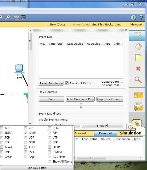
 and select only ICMP.")
18 Step 8: Verifying Connectivity in Simulation Mode Be sure you are in Simulation mode. Deselect all filters (All/None) and select only ICMP. 18
19

20 Select the Add Simple PDU tool used to ping devices.. Click once on PC0, then once on PC3. Continue clicking Capture/Forward button until the ICMP ping is completed. You should see the ICMP messages move between the hosts, hub and switch. The PDU Last Status should show as Successful. Click on Clear Event List if you do not want to look at the events or click Preview Previous Events if you do. For this exercise it does not matter. 20


21 Step 9: Saving the Topology Perform the following steps to save the topology (uses.pkt file extension). 21


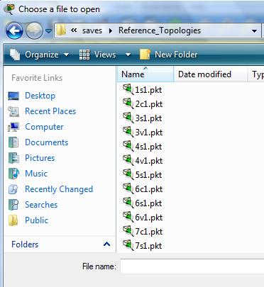
22 Opening Existing Topologies Opening Existing PT Topologies 22
23 Part III: Packet Tracer Lab Working with the Application Layer: DHCP, DNS, HTTP, HTTPS, This is an example of what your final topology should look like. Instructions: 1. Start Packet Tracer using Realtime mode. Options -> Preferences o Enable Show Link Lights o Disable Hide Device Label 2. Configuring the DHCP Server Add a server. Global Settings: Change the Display Name to DHCP Server Set the Gateway to FastEthernet: Set the IP address to Set the Subnet Mask to HTTP: Set HTTP Service and HTTPS Service to Off 23
24 DHCP: Set the Default Gateway to Set the DNS Server to Set the Start IP Address to DNS: Set the Service to Off Set the SMTP Service and POP3 Service to Off 2. Configuring the DNS Server Add a server. Global Settings: Change the Display Name to DNS Server Set the Gateway to FastEthernet: Set the IP address to Set the Subnet Mask to HTTP: Set HTTP Service and HTTPS Service to Off DHCP: Set the Service to Off DNS: Entering the Domain Name Enter for the Domain Name Enter for IP Address Click Add Entering the Domain Name Enter for the Domain Name Enter for IP Address Click Add Set the SMTP Service and POP3 Service to Off 3. Configuring the Web Server Add a server. Global Settings: Change the Display Name to Web Server: Set the Gateway to FastEthernet: Set the IP address to Set the Subnet Mask to
25 DHCP: Set the Service to Off DNS: Set the Service to Off HTTP Set the both the HTTP and HTTPS Service to On Change the sentence, <hr> Welcome to Cisco Packet Tracer. Opening doors to new opportunities. Mind Wide Open. to <hr> Welcome to Mapua Institute s of Technology s public web page! You may add other information as well. Set the SMTP Service and POP3 Service to Off 4. Configuring the Web Server Add a server. Global Settings: Change the Display Name to Web Server: Set the Gateway to FastEthernet: Set the IP address to Set the Subnet Mask to DHCP: Set the Service to Off DNS: Set the Service to Off HTTP: Change the sentence, <hr> Welcome to Cisco Packet Tracer. Opening doors to new opportunities. Mind Wide Open. to <hr> This is the corporate internal network! You may add other information as well. 5. Configuring the mail.mapua.edu Server Add a server. Global Settings: Change the Display Name to Server: mail.mapua.edu Set the Gateway to FastEthernet: Set the IP address to Set the Subnet Mask to
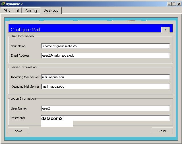
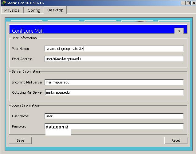
26 DHCP: Set the Service to Off DNS: Set the Service to Off HTTP: Set HTTP Service and HTTPS Service to Off Set SMTP and POP3 Service to On. Set the domain name to mail.mapua.edu Setup three user accounts as follows: Users Password user1 datacom1 user2 datacom2 user3 datacom3 6. Configure Two Client Computers using DHCP Add two client computers. Global Settings: Change the Display Names to Dynamic 1 and to Dynamic 2 respectively Set the Gateway/DNS to DHCP FastEthernet: Set the IP Configuration to DHCP 6. Configure One Client Computers using Static IP Addressing Add two client computers. Global Settings: Change the Display Name to Static Set the Gateway/DNS to Static Set Gateway to Set the DNS Server to FastEthernet: Be sure the configuration is set to Static Set the IP address to Set the Subnet Mask to

27 7. Configure Configuration for Clients 27
28 28
29 8. Adding switches Add two switches. Connect the servers to one switch using a straight-through cable. Connect the client computers to the other switch using a straight-through cable. Interconnect the two switches using a crossover cable. 9. Verify connectivity Ping (ICMP) o From a client computer use the Desktop Command prompt to ping the other client computers and the servers. o Example: From the Dynamic 1 client, C> ping o The first one or two pings may fail, but you should receive a reply on the later pings. This is due to the ping timing out while the ARP process takes place. Web Browser (HTTP) o On the client computers use the Desktop Web Browser, enter the URLs of the Web Servers and o You should see the web pages that you created on these servers. (SMTP) o From client computer (Dynamic 1), compose an (from Desktop tab) to another client computer (Static). To: user3@mail.mapua.edu o Upon sending the , check if was received by Static PC by clicking the icon (Desktop tab), and clicking the Receive button after. Please approach your instructor to verify connectivity of devices Instructor s Signature: 29
30 10. Using Simulation Mode Click on Simulation. Note: To reset a simulation, click on Reset Simulation Click on Edit Filters Choose Show All/None so that all the boxes (protocols) are unchecked. Select (check) the following protocols: DHCP, ICMP, HTTP, DNS, HTTPS, SMTP Web Browser (HTTP) On the client computers use the Desktop Web Browser, enter the URLs of the Web Servers or Click on Auto Capture/Play (automatically forwards the packets) or Capture Forward (must keep clicking to advance the packets) DHCP Reset the simulation by clicking on Reset Simulation To view DHCP, on one of the Dynamic client computers using DHCP go to the Desktop Command prompt. To have the client computer ask for new IP address and other information from the DHCP server, enter the command: C> ipconfig /renew Reset the simulation by clicking on Reset Simulation To view , click on one of the client computers sending to another client computer. Click on Auto Capture/Play (automatically forwards the packets) or Capture Forward (must keep clicking to advance the packets) 30
31 Questions: 1. With the activity conducted, briefly describe the function of the following application layer protocols: a. HTTP b. HTTPS c. DHCP d. DNS e. SMTP 2. Under Simulation mode, click Dynamic 1, then Command Prompt (on Desktop tab), then execute ipconfig /release, then ipconfig /renew. Click Auto Capture/Play (automatically forwards the packets) or Capture Forward (must keep clicking to advance the packets) until Packet Tracer finishes simulation (or reach Buffer Full Status). On the simulation panel, look for the frame DHCP /16 (Last Device column) and Switch1 (At Device column). Click the Info square-colored area on the Info column. Click Outbound PDU details at the PDU information. Preamble Source MAC address Destination MAC address Type field value Source IP address Destination IP address Answer 31
32 a. A connection-oriented communication is where the sender and receiver must prearrange for communications to occur, otherwise communications fails. Connectionless services do not prearrange for communications to occur. Connection-oriented services use TCP as its transport layer protocol whereas connectionless services use UDP. Is DHCP a connection-oriented service or a connectionless service? Is DHCP running TCP or UDP services? What is the source port used by DHCP servers? b. From the five application protocols under study, identify the three protocols using TCP services. 3. Under Simulation mode, click Dynamic 2, then Command Prompt (on Desktop tab), then type the URL on the web browser. Similarly, do the same for Static PC, typing in Click Auto Capture/Play (automatically forwards the packets) or Capture Forward (must keep clicking to advance the packets) until Packet Tracer finishes simulation (or reach Buffer Full Status). a. Before the interaction of the clients using HTTP and HTTPS, what protocol was used first? b. What is the source port used by HTTP servers? HTTPS servers? c. Look at any PDU information containing an HTTP frame and another PDU information containing HTTPS frame. Look at the difference between the data stored via HTTP with that of HTTPS. 32
33 4. Under Simulation mode, click Dynamic 1, then send on one of the other client computers. Click Auto Capture/Play (automatically forwards the packets) or Capture Forward (must keep clicking to advance the packets) until Packet Tracer finishes simulation (or reach Buffer Full Status). a. Before the interaction of the clients using SMTP, what protocol was used first? b. What is the source port used by servers running SMTP? 5. By identifying the protocols serviced by TCP and UDP, identify three fields present in TCP that are not found in UDP. 6. Perform a ping from Dynamic 1 to Dynamic 2 under Simulation mode. Note: Before doing a ping, type in arp d at the command prompt of Dynamic 1 and execute arp a after. Internet address and Physical address must be empty after typing arp -a a. Before the interaction of the clients with ping, what protocol was used first? b. Execute arp a after the successful ping. Write down the internet address and physical address on Dynamic 1. 33
34 c. Analyze the first ICMP frame and complete the table below. Source IP Address Destination IP Address ICMP Type value ICMP Code value Source Ethernet Address Destination Ethernet Address Internet Protocol version Time to Live (TTL) value Answer 34
Department Of Computer Science
 Department Of Computer Science Laboratory Manual Prepared By: Muhammad Nouman Farooq Lecturer and Course Coordinator Course: Computer Communication and Networks (CS-205) Page 1 of 43 Table of Contents
Lab#01 - Introduction to Packet Tracer
 Lab#01 - Introduction to Packet Tracer What is Packet Tracer? Packet Tracer is a protocol simulator developed by Dennis Frezzo and his team at Cisco Systems. Packet Tracer (PT) is a powerful and dynamic
Introduction to the Packet Tracer Interface using a Hub Topology
 Introduction to Packet Tracer What is Packet Tracer? Packet Tracer is a protocol simulator developed by Dennis Frezzo and his team at Cisco Systems. Packet Tracer (PT) is a powerful and dynamic tool that
Use of the TCP/IP Protocols and the OSI Model in Packet Tracer
 Communication Networks [Netw501] Spring 2018 Tutorial 3 Packet Tracer Activity 3 Use of the TCP/IP Protocols and the OSI Model in Packet Tracer Introduction: In Packet Tracer simulation mode, detailed
Packet Tracer - Explore a Network
 Topology Objectives Part 1: Examine Internetwork Traffic at Branch Part 2: Examine Internetwork Traffic to Central Part 3: Examine Internet Traffic from Branch Background This simulation activity is intended
GAME100 Lab 5. Before beginning the lab, please download and install Cisco Packet Trace
 GAME100 Lab 5 Name: Part 1: Learn to Use Packet Tracer Objectives Develop an understanding of the basic functions of Packet Tracer. Create/model a simple Ethernet network using two hosts and a switch.
Packet Tracer - Investigating the TCP/IP and OSI Models in Action (Instructor Version Optional Packet Tracer)
") (Instructor Version Optional Packet Tracer) Instructor Note: Red font color or gray highlights indicate text that appears in the instructor copy only. Optional activities are designed to enhance understanding
(Instructor Version Optional Packet Tracer) Instructor Note: Red font color or gray highlights indicate text that appears in the instructor copy only. Optional activities are designed to enhance understanding
Internetworking with Packet Tracer
 Internetworking with Packet Tracer Objectives Develop an understanding of the basic functions of Packet Tracer. Create/model two simple Ethernet networks connected by a switch. Observe traffic behavior
Packet Tracer Simulation - TCP and UDP Communications
 Topology Objectives Part 1: Generate Network Traffic in Simulation Mode Part 2: Examine the Functionality of the TCP and UDP Protocols Background This simulation activity is intended to provide a foundation
Packet Tracer Create a Simple Network Using Packet Tracer
 Using Packet Tracer Topology Addressing Table Device Interface IP Address Subnet Mask Default Gateway PC Ethernet0 DHCP 192.168.0.1 Wireless Router Cisco.com Server LAN 192.168.0.1 255.255.255.0 Internet
Packet Tracer: Novice Session. Packet Tracer: Novice Session 2007 Cisco Systems, Inc. All rights reserved. Cisco Public
 Packet Tracer: Novice Session Packet Tracer: Novice Session 1 How Can I Use Packet Tracer? Problem Scenario: Your students need to learn how to configure a router Ethernet interface and to verify connectivity
NET323 D: NETWORKS PROTOCOLS
 1 NET323 D: NETWORKS PROTOCOLS Networks and Communication Systems Department TA. Anfal AlHazzaa Lab # 2 : Hub Vs. Switch Lab Objectives 2 To create two small LANs contain three PCs using Packet Tracer
Lab IP Addresses and Network Communication
 Lab 3.5.2 IP Addresses and Network Communication Objectives Build a simple peer-to-peer network and verify physical connectivity. Assign various IP addresses to hosts and observe the effects on network
NET323 D: NETWORKS PROTOCOLS
 1 NET323 D: NETWORKS PROTOCOLS Networks and Communication Systems Department Lab # 1 : Introduction to Packet Tracer Lab Objectives 2 To become familiar with Packet Tracer Interface To differentiate between
Packet Tracer: Novice Session 2007 Cisco Systems, Inc. All rights reserved. Cisco Public. Packet Tracer: Novice Session
 Packet Tracer: Novice Session Packet Tracer: Novice Session 1 How Can I Use Packet Tracer? Problem Scenario: Your students need to learn how to configure a router Ethernet interface and to verify connectivity
CNBK Communications and Networks Lab Book: Purpose of Hardware and Protocols Associated with Networking Computer Systems
 Lab Book: Purpose of Hardware and Protocols Associated with Networking Computer Systems Contents Purpose of Hardware and Protocols Associated with Computer Networks... 3 Lab Objectives... 3 Lab Resources...
CNPE Communications and Networks Lab Book: Data Transmission Over Digital Networks
 Lab Book: Data Transmission Over Digital Networks Contents Data Transmission Over Digital Networks... 3 Lab Objectives... 3 Lab Resources... 3 Task 1 Build the Home Network... 3 Task 2 Configure IP Addresses...
Lab - Configure a NIC to Use DHCP in Windows
 Introduction In this lab, you will configure an Ethernet NIC to use DHCP to obtain an IP address and test connectivity between two computers. Recommended Equipment Wireless router Two computers running
PreLab for CS356 Lab NIL (Lam) (To be submitted when you come for the lab)
 (To be submitted when you come for the lab)") PreLab for CS356 Lab NIL (Lam) (To be submitted when you come for the lab) Name: UT EID: 1. Differentiate between Routers, Switches, and Hubs. 2. Explain subnet masks. 3. For this lab, where is subnet
PreLab for CS356 Lab NIL (Lam) (To be submitted when you come for the lab) Name: UT EID: 1. Differentiate between Routers, Switches, and Hubs. 2. Explain subnet masks. 3. For this lab, where is subnet
Lab - Connect to a Router for the First Time
 Introduction In this lab, you will configure basic settings on a wireless router. Recommended Equipment A computer with Windows installed An Ethernet NIC installed Wireless router Ethernet patch cable
1. Which OSI layers offers reliable, connection-oriented data communication services?
 CCNA 1 Practice Final Exam Answers v4.0 100% 1. Which OSI layers offers reliable, connection-oriented data communication services? application presentation session transport network 2. Refer to the exhibit.
EXAM - HP0-Y52. Applying HP FlexNetwork Fundamentals. Buy Full Product.
 HP EXAM - HP0-Y52 Applying HP FlexNetwork Fundamentals Buy Full Product http://www.examskey.com/hp0-y52.html Examskey HP HP0-Y52 exam demo product is here for you to test the quality of the product. This
CS356 Lab NIL (Lam) In this lab you will learn: Cisco 2600 Router Configuration Static Routing PartB 20 min Access Control Lists PartC 30 min Explore!
 In this lab you will learn: Cisco 2600 Router Configuration Static Routing PartB 20 min Access Control Lists PartC 30 min Explore!") CS356 Lab NIL (Lam) In this lab you will learn: PartA Time: 2 hrs 40 min Cisco 2600 Router Configuration Static Routing PartB 20 min Access Control Lists PartC 30 min Explore! Components used: 2 computers
CS356 Lab NIL (Lam) In this lab you will learn: PartA Time: 2 hrs 40 min Cisco 2600 Router Configuration Static Routing PartB 20 min Access Control Lists PartC 30 min Explore! Components used: 2 computers
NETWORK LAB 2 Configuring Switch Desktop
 Configuring Switch 1. Select the switch tab and then add a switch from the list of switches we have to the workspace, we will choose (2950-24) switch. 2. Add a number of PCs next to the switch in order
CS 326e Lab 2, Edmondson-Yurkanan, Spring 2004 Router Configuration, Routing and Access Lists
 CS 326e Lab 2, Edmondson-Yurkanan, Spring 2004 Router Configuration, Routing and Access Lists Name: In this lab you will learn: PartA Cisco 2600 Router Configuration Static Routing PartB 20 min Dynamic
NET323 D: NETWORKS PROTOCOLS
 1 NET323 D: NETWORKS PROTOCOLS Networks and Communication Systems Department TA. Anfal AlHazzaa Lab # 8: DNS (Domain Name System) Lab Objectives 2 To understand how DNS works Lab Content 3 Introduction
Configuration and management of Networks LAB 1 Introduction to packet tracer
 LAB 1 Introduction to packet tracer Objectives: Learn Packet Tracer to design and simulate networks. Learn to create a simple LAN with two PCs using an Ethernet hub and two straight through cables to connect
Classful Address Subnet Mask Number of Hosts per Subnet (2 x 2)
") LAB 1 Exercise 1- Subnetting exercises. Write the subnet, broadcast address, and valid host range for question 1 through question 6: 1. 192.168.100.25/30 2. 192.168.100.37/28 3. 192.168.100.66/27 4. 192.168.100.17/29
LAB 1 Exercise 1- Subnetting exercises. Write the subnet, broadcast address, and valid host range for question 1 through question 6: 1. 192.168.100.25/30 2. 192.168.100.37/28 3. 192.168.100.66/27 4. 192.168.100.17/29
CS 356 Lab #1: Basic LAN Setup & Packet capture/analysis using Ethereal
 CS 356 Lab #1: Basic LAN Setup & Packet capture/analysis using Ethereal Tasks: Time: 2:00 hrs (Task 1-6 should take 45 min; the rest of the time is for Ethereal) 1 - Verify that TCP/IP is installed on
PT Activity: Configuring a Zone-Based Policy Firewall (ZPF)
") PT Activity: Configuring a Zone-Based Policy Firewall (ZPF) Instructor Version Topology Diagram Addressing Table Device Interface IP Address Subnet Mask Default Gateway R1 R2 R3 Fa0/1 192.168.1.1 255.255.255.0
PT Activity: Configuring a Zone-Based Policy Firewall (ZPF) Instructor Version Topology Diagram Addressing Table Device Interface IP Address Subnet Mask Default Gateway R1 R2 R3 Fa0/1 192.168.1.1 255.255.255.0
Activity Configuring and Securing a Wireless LAN in Packet Tracer
 Activity Configuring and Securing a Wireless LAN in Packet Tracer Objectives: 1. Configure a Wireless Access Point (WAP) local IP address. 2. Configure a WAP with an SSID. 3. Change the administrator s
Imi :... Data:... Nazwisko:... Stron:...
 Imi :.................................................... Data:....................... Nazwisko:............................................... Stron:...................... 1. Which of the following protocols
Lab 7.5.1: Basic Wireless Configuration
 Topology Diagram Learning Objectives Configure options in the Linksys Setup tab. Configure options in the Linksys Wireless tab. Configure options in the Linksys Administration tab. Configure options in
Packet Tracer - Using Traceroute to Discover the Network (Instructor Version)
") (Instructor Version) Instructor Note: Red font color or Gray highlights indicate text that appears in the instructor copy only. Topology Scenario The company you work for has acquired a new branch location.
(Instructor Version) Instructor Note: Red font color or Gray highlights indicate text that appears in the instructor copy only. Topology Scenario The company you work for has acquired a new branch location.
Lab - Configure Wireless Router in Windows
 Introduction In this lab, you will configure and test the wireless settings on a wireless router. Recommended Equipment A computer with Windows installed A Wireless NIC installed An Ethernet NIC installed
Packet Tracer Mini-Lab 04: Supplement Configuring 2 LANs and 2 Routers with Config in Packet Tracer
 Packet Tracer Mini-Lab 04: Supplement Configuring 2 LANs and 2 Routers with Config in Packet Tracer CAVEAT: THE LABS IN CC2-180 MAY NOT WORK ENTIRELY AS PLANNED. WE WILL BE UTILIZING BOTH A SERVER 2012
CCRI Networking Technology I CSCO-1850 Spring 2014
 CCRI Networking Technology I CSCO-1850 Spring 2014 Instructor John Mowry Telephone 401-825-2138 E-mail jmowry@ccri.edu Office Hours Room 2126 Class Sections 102 Monday & Wednesday 6:00PM-9:50PM, starts
CCNA 1 Final Exam Answers UPDATE 2012 eg.1
 CCNA 1 Final Exam Answers UPDATE 2012 eg.1 January 12th, 2012AdminLeave a commentgo to comments Which of the following are the address ranges of the private IP addresses? (Choose three.) 10.0.0.0 to 10.255.255.255
OSI Model with Protocols. Layer Name PDU Address Protocols Device
 NetEss Name: Networking Essentials Prof. CHIN OSI Model with Protocols Layer Name PDU Address Protocols Device 7 Application Data FTP, SSH, Telnet, SMTP, DNS TFTP,HTTP, POP3, IMAP, HTTPS 6 Presentation
Lab Correcting RIPv2 Routing Problems
 Lab 9.4.2 Correcting RIPv2 Routing Problems e Interface IP Address Subnet Mask Default Gateway Device Host Name Interface IP Address Subnet Mask Default Gateway R1 BRANCH1 Fast Ethernet 0/0 172.16.0.1
Device Interface IP Address Subnet Mask Default Gateway
 Topology Diagram Addressing Table Device Interface IP Address Subnet Mask Default Gateway BRANCH HQ ISP Fa0/0 172.20.1.129 255.255.255.128 N/A S0/0/0 172.20.1.1 255.255.255.128 N/A Fa0/0 172.20.0.129 255.255.255.128
Interconnecting Cisco Networking Devices Part1 ( ICND1) Exam.
 Exam.") Cisco 640-822 Interconnecting Cisco Networking Devices Part1 ( ICND1) Exam TYPE: DEMO http://www.examskey.com/640-822.html Examskey Cisco 640-822 exam demo product is here for you to test quality of the
Cisco 640-822 Interconnecting Cisco Networking Devices Part1 ( ICND1) Exam TYPE: DEMO http://www.examskey.com/640-822.html Examskey Cisco 640-822 exam demo product is here for you to test quality of the
CS 386M Lab 1 Router Configuration and Routing
 CS 386M Lab 1 Router Configuration and Routing In this lab you will learn: PartA Cisco 2600 Router Configuration Static Routing PartB 30 min Dynamic Routing PartC 40 min Explore! Components used in this
Network II Lab 03 Part 01: Ping command in simula on mode
 Network II Lab 03 Part 01: Ping command in simula on mode 1. Open the file saved from the previous lab. [Dr. Ahmed ElShafee, ACU Fall 2011, Network II] 1 / 18 2. add simple packet from client to server
Lab Using Wireshark to Examine Ethernet Frames
 Topology Objectives Part 1: Examine the Header Fields in an Ethernet II Frame Part 2: Use Wireshark to Capture and Analyze Ethernet Frames Background / Scenario When upper layer protocols communicate with
2. What flavor of Network Address Translation can be used to have one IP address allow many users to connect to the global Internet? A. NAT B.
 How long is an IPv6 address? A. 32 bits B. 128 bytes C. 64 bits D. 128 bits Answer: Option D An IPv6 address is 128 bits long. 2. What flavor of Network Address Translation can be used to have one IP address
Cisco Interconnecting Cisco Networking Devices Part 1.
 Cisco 100-105 Interconnecting Cisco Networking Devices Part 1 http://killexams.com/pass4sure/exam-detail/100-105 Question: 323 Refer to the exhibit. SwitchA receives the frame with the addressing shown.
Lab - Using Wireshark to Examine a UDP DNS Capture
 Topology Objectives Part 1: Record a PC s IP Configuration Information Part 2: Use Wireshark to Capture DNS Queries and Responses Part 3: Analyze Captured DNS or UDP Packets Background / Scenario If you
Activity Configuring Routers, Web, DHCP, DNS and FTP Servers
 Activity Configuring Routers, Web, DHCP, DNS and FTP Servers Objectives: 1. Configure a network using 2 routers, 4 switches, 6 servers and 8 PC s. 2. Assign network addresses. 3. Configure a DHCP server
Lab - Using Wireshark to Examine a UDP DNS Capture
 Topology Objectives Part 1: Record a PC s IP Configuration Information Part 2: Use Wireshark to Capture DNS Queries and Responses Part 3: Analyze Captured DNS or UDP Packets Background / Scenario If you
Lab Using Wireshark to Examine Ethernet Frames
 Topology Objectives Part 1: Examine the Header Fields in an Ethernet II Frame Part 2: Use Wireshark to Capture and Analyze Ethernet Frames Background / Scenario When upper layer protocols communicate with
Chapter 14: Introduction to Networking
 Chapter 14: Introduction to Networking Complete CompTIA A+ Guide to PCs, 6e How different networks are wired (or wireless) How to identify common network cables How Ethernet works About the OSI and TCP/IP
CCNA Exploration Network Fundamentals
 CCNA Exploration 4.0 1. Network Fundamentals The goal of this course is to introduce you to fundamental networking concepts and technologies. These online course materials will assist you in developing
Lab Capturing and Analyzing Network Traffic
 Lab 1.2.2 Capturing and Analyzing Network Traffic Host Name IP Address Fa0/0 Subnet Mask IP Address S0/0/0 Subnet Mask Default Gateway RouterA 172.17.0.1 255.255.0.0 192.168.1.1 (DCE) 255.255.255.0 N/A
IPR10. Quick Start Guide and Application Notes
 IPR10 Quick Start Guide and Application Notes Model: IPR10 Quick Start and Application Notes The IPR10 is an access router with asynchronous serial RS-232 interface for use with dial-up modems, leased
CCNA Exam File with Answers. Note: Underlines options are correct answers.
 CCNA Exam File with Answers. Note: Underlines options are correct answers. 1. Which of the following are ways to provide login access to a router? (choose all that apply) A. HTTP B. Aux Port /TELNET C.
D-Link (Europe) Ltd. 4 th Floor Merit House Edgware Road London HA7 1DP U.K. Tel: Fax:
 Ltd. 4 th Floor Merit House Edgware Road London HA7 1DP U.K. Tel: Fax:") Product: DFL-500 Internet Firewall Index Setup Introduction...2 Set Up Using Web Configurator...3 Setting Up Internal IP Address using CLI...4 Setting UP External IP Address Manually Using CLI...4 How
Product: DFL-500 Internet Firewall Index Setup Introduction...2 Set Up Using Web Configurator...3 Setting Up Internal IP Address using CLI...4 Setting UP External IP Address Manually Using CLI...4 How
A+ Certification Guide. Chapter 16 (Part B) Networking
 Networking") A+ Certification Guide Chapter 16 (Part B) Networking Chapter 16 (Part B) Objectives Installing and Configuring Network Interface Cards Networking Configuration for Small Network Switches and Routers Setting
A+ Certification Guide Chapter 16 (Part B) Networking Chapter 16 (Part B) Objectives Installing and Configuring Network Interface Cards Networking Configuration for Small Network Switches and Routers Setting
BSc Year 2 Data Communications Lab - Using Wireshark to View Network Traffic. Topology. Objectives. Background / Scenario
 BSc Year 2 Data Communications Lab - Using Wireshark to View Network Traffic Topology Objectives Part 1: (Optional) Download and Install Wireshark Part 2: Capture and Analyze Local ICMP Data in Wireshark
Networking Notes. Common Internet Speeds. Online Speed Test myspeed.visualware.com
 Networking Notes Common Internet Speeds Dial Up 56 kbs 1000kbs = 1 mbs (1 user capacity) DSL 1.5 mbs (1 channel 10 user capacity) T1 1.5 mbs (24 channel 500 user capacity) Scalable Ethernet (Adjustable
This document is exclusive property of Cisco Systems, Inc. Permission is granted to print and copy this document for non-commercial distribution and
 This document is exclusive property of Cisco Systems, Inc. Permission is granted to print and copy this document for non-commercial distribution and exclusive use by instructors in the CCNA Exploration:
Lab 1.3.2: Review of Concepts from Exploration 1 - Challenge
 Lab 1.3.2: Review of Concepts from Exploration 1 - Challenge Topology Diagram Learning Objectives Upon completion of this lab, you will be able to: Create a logical topology given network requirements
8.9.2 Lab: Configure an Ethernet NIC to use DHCP in Windows Vista
 8.9.2 Lab: Configure an Ethernet NIC to use DHCP in Windows Vista Introduction If Vista is not available in your classroom, you may complete this lab by viewing the figures in this document. Print and
Lab Configure Cisco IOS Firewall CBAC on a Cisco Router
 Lab 3.8.3 Configure Cisco IOS Firewall CBAC on a Cisco Router Objective Scenario Topology Estimated Time: 35 minutes Number of Team Members: Two teams with four students per team In this lab, students
Chapter 2. Switch Concepts and Configuration. Part I
 Chapter 2 Switch Concepts and Configuration Part I CCNA3-1 Chapter 2-1 Note for Instructors These presentations are the result of a collaboration among the instructors at St. Clair College in Windsor,
Network II Lab 01. Part 01: Interface Overview. Program interface
 Part 01: Interface Overview Network II Lab 01 This initial interface contains ten components. If you are unsure of what a particular interface item does, move your mouse over the item and a help balloon
Lab 6: Access Lists. Device Interface IP Address Subnet Mask Gateway/Clock Rate Fa 0/ R1
 Lab 6: Access Lists Network Topology:- Device Interface IP Address Subnet Mask Gateway/Clock Rate Fa 0/0 192.168.0.1 255.255.255.0 ----- R1 Fa 0/1 192.168.10.1 255.255.255.0 ----- Se 0/0/0 10.0.0.1 255.255.255.252
Cisco EXAM CCNA Cisco Certified Network Associate. Buy Full Product.
 Cisco EXAM - 200-120 CCNA Cisco Certified Network Associate Buy Full Product http://www.examskey.com/200-120.html Examskey Cisco 200-120 exam demo product is here for you to test the quality of the product.
PT Activity 5.6.1: Packet Tracer Skills Integration Challenge Topology Diagram
 Topology Diagram All contents are Copyright 2008 Cisco Systems, Inc. All rights reserved. This document is Cisco Public Information. Page 1 of 6 Addressing Table Device Interface IP Address Subnet Mask
DHCP in. Introduction. Step 1 router. In this lab, you. computer. Page 1 of 7
 Essentials 5.0 6.3.2.7 Lab - Configure a NIC to Use DHCP in Windows 7 Introduction Print and complete this lab. In this lab, you will configure an Ethernet NIC to use DHCP to obtain an IP address and testt
LevelOne FBR User s Manual. 1W, 4L 10/100 Mbps ADSL Router. Ver
 LevelOne FBR-1416 1W, 4L 10/100 Mbps ADSL Router User s Manual Ver 1.00-0510 Table of Contents CHAPTER 1 INTRODUCTION... 1 FBR-1416 Features... 1 Package Contents... 3 Physical Details... 3 CHAPTER 2
Lab Configuring an ISR with SDM Express
 Lab 5.2.3 Configuring an ISR with SDM Express Objectives Configure basic router global settings router name, users, and login passwords using Cisco SDM Express. Configure LAN and Internet connections on
Cisco 1: Networking Fundamentals
 Western Technical College 10150110 Cisco 1: Networking Fundamentals Course Outcome Summary Course Information Description Career Cluster Instructional Level Total Credits 3.00 Total Hours 90.00 This course
CCNA 1 Final Exam Answers UPDATE 2012 eg.2
 CCNA 1 Final Exam Answers UPDATE 2012 eg.2 January 12th, 2012AdminLeave a commentgo to comments 1. When must a router serial interface be configured with the clock rate command? when the interface is functioning
AT&T Digital Subscriber Line Service
 AT&T Digital Subscriber Line Service Windows 2000 Professional PC Configuration Guide Overview Welcome to AT&T DSL Internet Service! This guide is designed to help you configure your PC to access the Internet
2. Which two functions of the OSI model occur at layer two? (Choose two.) physical addressing encoding routing cabling media access control
 physical addressing encoding routing cabling media access control") 1. Which of the following are the address ranges of the private IP addresses? (Choose three.) 10.0.0.0 to 10.255.255.255 200.100.50.0 to 200.100.25.255 150.150.0.0 to 150.150.255.255 172.16.0.0 to 172.31.255.255
1. Which of the following are the address ranges of the private IP addresses? (Choose three.) 10.0.0.0 to 10.255.255.255 200.100.50.0 to 200.100.25.255 150.150.0.0 to 150.150.255.255 172.16.0.0 to 172.31.255.255
This course prepares candidates for the CompTIA Network+ examination (2018 Objectives) N
 N") CompTIA Network+ (Exam N10-007) Course Description: CompTIA Network+ is the first certification IT professionals specializing in network administration and support should earn. Network+ is aimed at IT
CompTIA Network+ (Exam N10-007) Course Description: CompTIA Network+ is the first certification IT professionals specializing in network administration and support should earn. Network+ is aimed at IT
CCNA Security 1.0 Student Packet Tracer Manual
 1.0 Student Packet Tracer Manual This document is exclusive property of Cisco Systems, Inc. Permission is granted to print and copy this document for non-commercial distribution and exclusive use by instructors
Defining Networks with the OSI Model. Module 2
 Defining Networks with the OSI Model Module 2 Objectives Skills Concepts Objective Domain Description Objective Domain Number Understanding OSI Basics Defining the Communications Subnetwork Defining the
Configure the Catalyst Express 500 Switch with Cisco Network Assistant
 Cisco SMB Support Assistant Cisco Profile Contacts & Feedback Help Configure the Catalyst Express 500 Switch with Cisco Network Assistant Home > Work With My Switches > Cisco Catalyst Switches > Configure
Lab Configuring Static Routes Instructor Version 2500
 Lab 6.1.6 Configuring Static Routes Instructor Version 2500 Objective Configure static routes between routers to allow data transfer between routers without the use of dynamic routing protocols. Background/Preparation
OHLONE COLLEGE Ohlone Community College District OFFICIAL COURSE OUTLINE
 OHLONE COLLEGE Ohlone Community College District OFFICIAL COURSE OUTLINE I. Description of Course: 1. Department/Course: CNET - 155A 2. Title: Introduction to Networks (CCNA1) 3. Cross Reference: 4. Units:
Lab : Challenge OSPF Configuration Lab. Topology Diagram. Addressing Table. Default Gateway. Device Interface IP Address Subnet Mask
 Topology Diagram Addressing Table Device Interface IP Address Subnet Mask Default Gateway Fa0/0 HQ S0/0/0 S0/0/1 Lo1 10.10.10.1 255.255.255.252 Fa0/0 Branch1 S0/0/0 S0/0/1 Fa0/0 Branch2 S0/0/0 S0/0/1 PC1
CCNA 1 Chapter 5 v5.0 Exam Answers 2013
 CCNA 1 Chapter 5 v5.0 Exam Answers 2013 1 2 A host is trying to send a packet to a device on a remote LAN segment, but there are currently no mappings in its ARP cache. How will the device obtain a destination
Lab Troubleshooting LAN Connectivity
 Lab 9.2.4 Troubleshooting LAN Connectivity Device Host Name Interface IP Address Subnet Mask Default Gateway Switch Port R1 R1 Fast Ethernet 0/0 192.168.1.1 255.255.255.0 N/A Fast Ethernet 0/2 S1 S1 VLAN
Packet Tracer - Connect a Router to a LAN (Instructor Version)
") (Instructor Version) Instructor Note: Red font color or gray highlights indicate text that appears in the instructor copy only. Topology Addressing Table Device Interface IP Address Subnet Mask Default
(Instructor Version) Instructor Note: Red font color or gray highlights indicate text that appears in the instructor copy only. Topology Addressing Table Device Interface IP Address Subnet Mask Default
Quick Installation Guide of Acer WLAN 11b Broadband Router
 Preparation 1 At lease one PC with IEEE802.11b WLAN client installed. 2 One straight-through Category 5 Ethernet cable, used to link WAN interface to xdsl or CM for Internet connection. 3 Acer WLAN 11b
Troubleshooting Network analysis Software communication tests and development Education. Protocols used for communication (10 seconds capture)
") Lab 1 Wireshark Wireshark is an open source and free packet analyser used for many purposes, such as: Troubleshooting Network analysis Software communication tests and development Education This reports
Lab 1 Wireshark Wireshark is an open source and free packet analyser used for many purposes, such as: Troubleshooting Network analysis Software communication tests and development Education This reports
Homework 4 assignment for ECE374 Posted: 04/06/15 Due: 04/13/15
 ECE374: Homework 4 1 Homework 4 assignment for ECE374 Posted: 04/06/15 Due: 04/13/15 Note: In all written assignments, please show as much of your work as you can. Even if you get a wrong answer, you can
NET323 D: NETWORKS PROTOCOLS
 1 NET323 D: NETWORKS PROTOCOLS Networks and Communication Systems Department TA. Anfal AlHazzaa Lab # 6 : Dynamic Route (OSPF Single area) Lab Objectives 2 To connect small LANs using routers. To configure
Exam E1 Copyright 2010 Thaar AL_Taiey
 Exam E1 2 Exam E1 E1-1. Which of the following statements is true regarding the internetwork shown in Figure E1-1? (Select all that apply) Figure E1-1 A Sample Internetwork A. The link number 15 uses a
CHAPTER 7 ADVANCED ADMINISTRATION PC
 ii Table of Contents CHAPTER 1 INTRODUCTION... 1 Broadband ADSL Router Features... 1 Package Contents... 3 Physical Details... 4 CHAPTER 2 INSTALLATION... 6 Requirements... 6 Procedure... 6 CHAPTER 3 SETUP...
Networking Fundamentals Tom Brett
 Networking Fundamentals Tom Brett Data Before we look at networking, it is important for us to understand what Data is and how it is stored and represented Data According to Webopedia, data is distinct
Lab DHCP Client Setup
 Lab 9.3.5 DHCP Client Setup Objective The purpose of this lab is to introduce Dynamic Host Configuration Protocol (DHCP) and the process for setting up a network computer as a DHCP client to use DHCP services.
Laboration 1 Examine the Topology and Basic Troubleshooting Commands
 Laboration 1 Examine the Topology and Basic Troubleshooting Commands Topology All contents are Copyright 1992 2011 Cisco Systems, Inc. All rights reserved. This document is Cisco Public Information. Page
Release Notes CCNA Exploration: Routing Protocols and Concepts Release
 Release Notes CCNA Exploration: Routing Protocols and Concepts Release 4.0.5.0 Purpose Release 4.0.5.0 of Routing Protocols and Concepts is the fifth maintenance release of the second course in the CCNA
Access Switch VLAN Y Y.1 /24
 Topology: Fa 0/1 VNC Server Fa 0/0 Port B Access Router Trunk VLAN X Access Switch VLAN Y Backbone Router 141.85.Y.1 /24 28.0.0.42 OSPF X.0.0.0/8 Port A 27.45.67.89 Work Station DHCP Server The Goal: Connect
on the bottom left hand corner you will find all the devices you need.
 Create a simple LAN in packet tracer Things you will need 1) Generic PC 1) Switch 1) Server open packet tracer on the bottom left hand corner you will find all the devices you need. Click on END DEVICES
Lab Student Lab Orientation
 Lab 1.1.1 Student Lab Orientation Objective In this lab, the students will complete the following tasks: Review the lab bundle equipment Understand the security pod topology Understand the pod naming and
Packet Tracer Mini-Lab 08: Supplement Configuring 2 LANs/2 Routers using Config, CLI, & RIPv2
 Packet Tracer Mini-Lab 08: Supplement Configuring 2 LANs/2 Routers using Config, CLI, & RIPv2 CAVEAT: THE LABS IN CC2-180 MAY NOT WORK ENTIRELY AS PLANNED. WE WILL BE UTILIZING BOTH A SERVER 2012 R2 HOST