Chapter 11 Data Link Control 11.1
|
|
|
- Bernice Peters
- 6 years ago
- Views:
Transcription
1 Chapter 11 Data Link Control 11.1 Copyright The McGraw-Hill Companies, Inc. Permission required for reproduction or display.
2 FRAMING The data link layer needs to pack bits into frames,, so that each frame is distinguishable from another. Our postal system practices a type of framing. The simple act of inserting a letter into an envelope separates one piece of information from another; the envelope serves as the delimiter. Topics discussed in this section: Fixed-Size Framing Variable-Size Framing 11.2
3 11.3 Figure 11.1 A frame in a character-oriented protocol

4 11.4 Figure 11.2 Byte stuffing and unstuffing
5 Note Byte stuffing is the process of adding 1 extra byte whenever there is a flag or escape character in the text. 11.5

6 11.6 Figure 11.3 A frame in a bit-oriented protocol
7 Note Bit stuffing is the process of adding one extra 0 whenever five consecutive 1s follow a 0 in the data, so that the receiver does not mistake the pattern for a flag. 11.7
8 11.8 Figure 11.4 Bit stuffing and unstuffing
9 FLOW AND ERROR CONTROL The most important responsibilities of the data link layer are flow control and error control.. Collectively, these functions are known as data link control. Topics discussed in this section: Flow Control Error Control 11.9
10 Note Flow control refers to a set of procedures used to restrict the amount of data that the sender can send before waiting for acknowledgment
11 Note Error control in the data link layer is based on automatic repeat request, which is the retransmission of data
12 PROTOCOLS Now let us see how the data link layer can combine framing, flow control, and error control to achieve the delivery of data from one node to another. The protocols are normally implemented in software by using one of the common programming languages. To make our discussions language-free, we have written in pseudocode a version of each protocol that concentrates mostly on the procedure instead of delving into the details of language rules

13 11.13 Figure 11.5 Taxonomy of protocols discussed in this chapter
14 NOISELESS CHANNELS Let us first assume we have an ideal channel in which no frames are lost, duplicated, or corrupted. We introduce two protocols for this type of channel. Topics discussed in this section: Simplest Protocol Stop-and-Wait Protocol 11.14

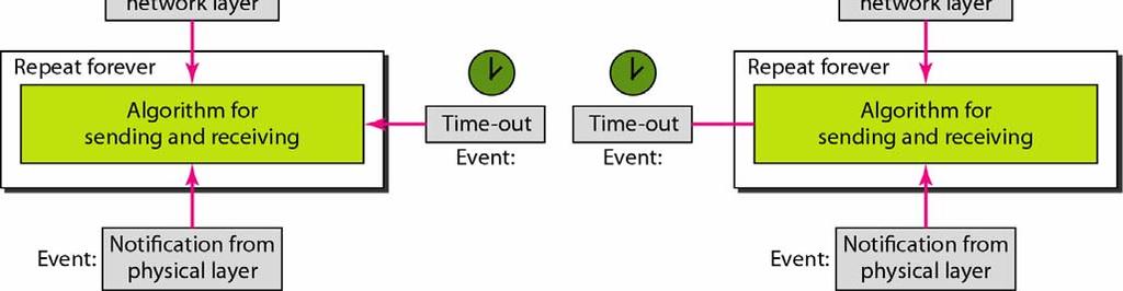
15 Figure 11.6 The design of the simplest protocol with no flow or error control 11.15

16 11.16 Algorithm 11.1 Sender-site algorithm for the simplest protocol


17 11.17 Algorithm 11.2 Receiver-site algorithm for the simplest protocol
18 Example 11.1 Figure 11.7 shows an example of communication using this protocol. It is very simple. The sender sends a sequence of frames without even thinking about the receiver. To send three frames, three events occur at the sender site and three events at the receiver site. Note that the data frames are shown by tilted boxes; the height of the box defines the transmission time difference between the first bit and the last bit in the frame

19 11.19 Figure 11.7 Flow diagram for Example 11.1

20 11.20 Figure 11.8 Design of Stop-and-Wait Protocol

21 11.21 Algorithm 11.3 Sender-site algorithm for Stop-and-Wait Protocol

22 11.22 Algorithm 11.4 Receiver-site algorithm for Stop-and-Wait Protocol
23 Example 11.2 Figure 11.9 shows an example of communication using this protocol. It is still very simple. The sender sends one frame and waits for feedback from the receiver. When the ACK arrives, the sender sends the next frame. Note that sending two frames in the protocol involves the sender in four events and the receiver in two events

24 11.24 Figure 11.9 Flow diagram for Example 11.2
25 NOISY CHANNELS Although the Stop-and and-wait Protocol gives us an idea of how to add flow control to its predecessor, noiseless channels are nonexistent. We discuss three protocols in this section that use error control. Topics discussed in this section: Stop-and-Wait Automatic Repeat Request Go-Back-N Automatic Repeat Request Selective Repeat Automatic Repeat Request 11.25
26 Note Error correction in Stop-and-Wait ARQ is done by keeping a copy of the sent frame and retransmitting of the frame when the timer expires
27 Note In Stop-and-Wait ARQ, we use sequence numbers to number the frames. The sequence numbers are based on modulo-2 arithmetic
28 Note In Stop-and-Wait ARQ, the acknowledgment number always announces in modulo-2 arithmetic the sequence number of the next frame expected
29 11.29 Figure Design of the Stop-and-Wait ARQ Protocol

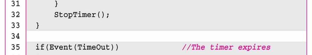
30 Algorithm 11.5 Sender-site algorithm for Stop-and-Wait ARQ (continued) 11.30

31 Algorithm 11.5 Sender-site algorithm for Stop-and-Wait ARQ (continued) 11.31


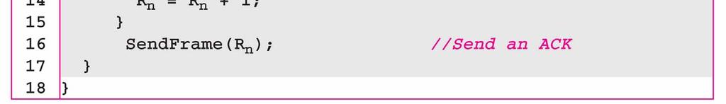
32 Algorithm 11.6 Receiver-site algorithm for Stop-and-Wait ARQ Protocol 11.32
33 Example 11.3 Figure shows an example of Stop-and-Wait ARQ. Frame 0 is sent and acknowledged. Frame 1 is lost and resent after the time-out. The resent frame 1 is acknowledged and the timer stops. Frame 0 is sent and acknowledged, but the acknowledgment is lost. The sender has no idea if the frame or the acknowledgment is lost, so after the time-out, it resends frame 0, which is acknowledged
34 11.34 Figure Flow diagram for Example 11.3
35 Example 11.4 Assume that, in a Stop-and-Wait ARQ system, the bandwidth of the line is 1 Mbps, and 1 bit takes 20 ms to make a round trip. What is the bandwidth-delay product? If the system data frames are 1000 bits in length, what is the utilization percentage of the link? Solution The bandwidth-delay product is 11.35
36 Example 11.4 (continued) The system can send 20,000 bits during the time it takes for the data to go from the sender to the receiver and then back again. However, the system sends only 1000 bits. We can say that the link utilization is only 1000/20,000, or 5 percent. For this reason, for a link with a high bandwidth or long delay, the use of Stop-and-Wait ARQ wastes the capacity of the link
37 Example 11.5 What is the utilization percentage of the link in Example 11.4 if we have a protocol that can send up to 15 frames before stopping and worrying about the acknowledgments? Solution The bandwidth-delay product is still 20,000 bits. The system can send up to 15 frames or 15,000 bits during a round trip. This means the utilization is 15,000/20,000, or 75 percent. Of course, if there are damaged frames, the utilization percentage is much less because frames have to be resent
38 Note In the Go-Back-N Protocol, the sequence numbers are modulo 2 m, where m is the size of the sequence number field in bits

39 11.39 Figure Send window for Go-Back-N ARQ
40 Note The send window is an abstract concept defining an imaginary box of size 2 m 1 with three variables: S f, S n, and S size
41 Note The send window can slide one or more slots when a valid acknowledgment arrives
42 11.42 Figure Receive window for Go-Back-N ARQ
43 Note The receive window is an abstract concept defining an imaginary box of size 1 with one single variable R n. The window slides when a correct frame has arrived; sliding occurs one slot at a time
44 11.44 Figure Design of Go-Back-N ARQ
45 11.45 Figure Window size for Go-Back-N ARQ
46 Note In Go-Back-N ARQ, the size of the send window must be less than 2 m ; the size of the receiver window is always

47 Algorithm 11.7 Go-Back-N sender algorithm (continued) 11.47


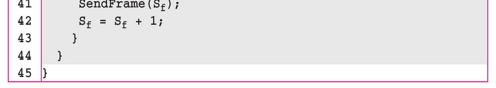
48 Algorithm 11.7 Go-Back-N sender algorithm (continued) 11.48

49 Algorithm 11.8 Go-Back-N receiver algorithm 11.49
50 11.50 Example 11.6 Figure shows an example of Go-Back-N. This is an example of a case where the forward channel is reliable, but the reverse is not. No data frames are lost, but some ACKs are delayed and one is lost. The example also shows how cumulative acknowledgments can help if acknowledgments are delayed or lost. After initialization, there are seven sender events. Request events are triggered by data from the network layer; arrival events are triggered by acknowledgments from the physical layer. There is no time-out event here because all outstanding frames are acknowledged before the timer expires. Note that although ACK 2 is lost, ACK 3 serves as both ACK 2 and ACK 3.

51 11.51 Figure Flow diagram for Example 11.6
52 Figure shows what happens when a frame is lost. Frames 0, 1, 2, and 3 are sent. However, frame 1 is lost. The receiver receives frames 2 and 3, but they are discarded because they are received out of order. The sender receives no acknowledgment about frames 1, 2, or 3. Its timer finally expires. The sender sends all outstanding frames (1, 2, and 3) because it does not know what is wrong. Note that the resending of frames 1, 2, and 3 is the response to one single event. When the sender is responding to this event, it cannot accept the triggering of other events. This means that when ACK 2 arrives, the sender is still busy with sending frame Example 11.7
53 Example 11.7 (continued) The physical layer must wait until this event is completed and the data link layer goes back to its sleeping state. We have shown a vertical line to indicate the delay. It is the same story with ACK 3; but when ACK 3 arrives, the sender is busy responding to ACK 2. It happens again when ACK 4 arrives. Note that before the second timer expires, all outstanding frames have been sent and the timer is stopped

54 11.54 Figure Flow diagram for Example 11.7
55 Note Stop-and-Wait ARQ is a special case of Go-Back-N ARQ in which the size of the send window is
56 11.56 Figure Send window for Selective Repeat ARQ
57 11.57 Figure Receive window for Selective Repeat ARQ


58 11.58 Figure Design of Selective Repeat ARQ
59 11.59 Figure Selective Repeat ARQ, window size
60 Note In Selective Repeat ARQ, the size of the sender and receiver window must be at most one-half of 2 m


61 Algorithm 11.9 Sender-site Selective Repeat algorithm (continued) 11.61

62 Algorithm 11.9 Sender-site Selective Repeat algorithm (continued) (continued)

63 Algorithm 11.9 Sender-site Selective Repeat algorithm (continued) 11.63

64 11.64 Algorithm Receiver-site Selective Repeat algorithm

65 11.65 Algorithm Receiver-site Selective Repeat algorithm

66 11.66 Figure Delivery of data in Selective Repeat ARQ
67 Example 11.8 This example is similar to Example 11.3 in which frame 1 is lost. We show how Selective Repeat behaves in this case. Figure shows the situation. One main difference is the number of timers. Here, each frame sent or resent needs a timer, which means that the timers need to be numbered (0, 1, 2, and 3). The timer for frame 0 starts at the first request, but stops when the ACK for this frame arrives. The timer for frame 1 starts at the second request, restarts when a NAK arrives, and finally stops when the last ACK arrives. The other two timers start when the corresponding frames are sent and stop at the last arrival event
68 Example 11.8 (continued) At the receiver site we need to distinguish between the acceptance of a frame and its delivery to the network layer. At the second arrival, frame 2 arrives and is stored and marked, but it cannot be delivered because frame 1 is missing. At the next arrival, frame 3 arrives and is marked and stored, but still none of the frames can be delivered. Only at the last arrival, when finally a copy of frame 1 arrives, can frames 1, 2, and 3 be delivered to the network layer. There are two conditions for the delivery of frames to the network layer: First, a set of consecutive frames must have arrived. Second, the set starts from the beginning of the window
69 Example 11.8 (continued) Another important point is that a NAK is sent after the second arrival, but not after the third, although both situations look the same. The reason is that the protocol does not want to crowd the network with unnecessary NAKs and unnecessary resent frames. The second NAK would still be NAK1 to inform the sender to resend frame 1 again; this has already been done. The first NAK sent is remembered (using the naksent variable) and is not sent again until the frame slides. A NAK is sent once for each window position and defines the first slot in the window
70 Example 11.8 (continued) The next point is about the ACKs. Notice that only two ACKs are sent here. The first one acknowledges only the first frame; the second one acknowledges three frames. In Selective Repeat, ACKs are sent when data are delivered to the network layer. If the data belonging to n frames are delivered in one shot, only one ACK is sent for all of them

71 11.71 Figure Flow diagram for Example 11.8


72 11.72 Figure Design of piggybacking in Go-Back-N ARQ
73 HDLC High-level Data Link Control (HDLC) is a bit-oriented protocol for communication over point-to to-point and multipoint links. It implements the ARQ mechanisms we discussed in this chapter. Topics discussed in this section: Configurations and Transfer Modes Frames Control Field 11.73
74 11.74 Figure Normal response mode

75 11.75 Figure Asynchronous balanced mode

76 11.76 Figure HDLC frames

77 11.77 Figure Control field format for the different frame types
78 11.78 Table 11.1 U-frame control command and response
79 Example 11.9 Figure shows how U-frames can be used for connection establishment and connection release. Node A asks for a connection with a set asynchronous balanced mode (SABM) frame; node B gives a positive response with an unnumbered acknowledgment (UA) frame. After these two exchanges, data can be transferred between the two nodes (not shown in the figure). After data transfer, node A sends a DISC (disconnect) frame to release the connection; it is confirmed by node B responding with a UA (unnumbered acknowledgment)


80 11.80 Figure Example of connection and disconnection
81 Example Figure shows an exchange using piggybacking. Node A begins the exchange of information with an I-frame numbered 0 followed by another I-frame numbered 1. Node B piggybacks its acknowledgment of both frames onto an I-frame of its own. Node B s first I-frame is also numbered 0 [N(S) field] and contains a 2 in its N(R) field, acknowledging the receipt of A s frames 1 and 0 and indicating that it expects frame 2 to arrive next. Node B transmits its second and third I-frames (numbered 1 and 2) before accepting further frames from node A
82 Example (continued) Its N(R) information, therefore, has not changed: B frames 1 and 2 indicate that node B is still expecting A s frame 2 to arrive next. Node A has sent all its data. Therefore, it cannot piggyback an acknowledgment onto an I-frame and sends an S-frame instead. The RR code indicates that A is still ready to receive. The number 3 in the N(R) field tells B that frames 0, 1, and 2 have all been accepted and that A is now expecting frame number


83 11.83 Figure Example of piggybacking without error
84 Example Figure shows an exchange in which a frame is lost. Node B sends three data frames (0, 1, and 2), but frame 1 is lost. When node A receives frame 2, it discards it and sends a REJ frame for frame 1. Note that the protocol being used is Go-Back-N with the special use of an REJ frame as a NAK frame. The NAK frame does two things here: It confirms the receipt of frame 0 and declares that frame 1 and any following frames must be resent. Node B, after receiving the REJ frame, resends frames 1 and 2. Node A acknowledges the receipt by sending an RR frame (ACK) with acknowledgment number


85 11.85 Figure Example of piggybacking with error
86 POINT-TO TO-POINT PROTOCOL Although HDLC is a general protocol that can be used for both point-to to-point and multipoint configurations, one of the most common protocols for point-to to-point access is the Point-to to-point Protocol (PPP). PPP is a byte-oriented protocol. Topics discussed in this section: Framing Transition Phases Multiplexing Multilink PPP 11.86

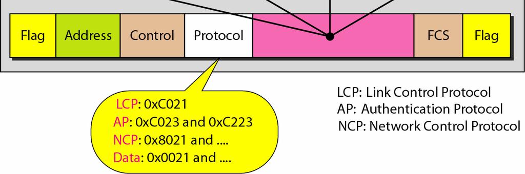
87 11.87 Figure PPP frame format
88 Note PPP is a byte-oriented protocol using byte stuffing with the escape byte
89 11.89 Figure Transition phases

90 11.90 Figure Multiplexing in PPP

91 11.91 Figure LCP packet encapsulated in a frame


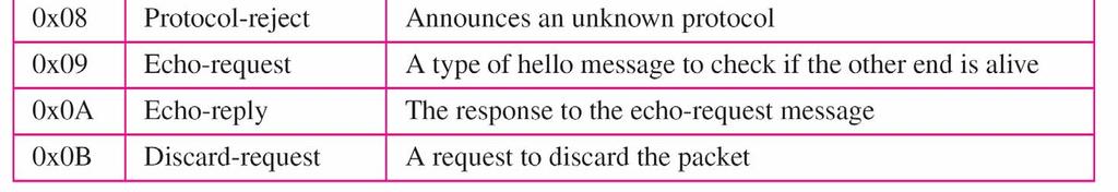
92 11.92 Table 11.2 LCP packets

93 11.93 Table 11.3 Common options

94 11.94 Figure PAP packets encapsulated in a PPP frame

95 11.95 Figure CHAP packets encapsulated in a PPP frame

96 11.96 Figure IPCP packet encapsulated in PPP frame

97 11.97 Table 11.4 Code value for IPCP packets

98 11.98 Figure IP datagram encapsulated in a PPP frame

99 11.99 Figure Multilink PPP
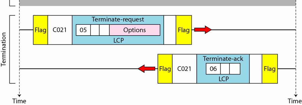
100 Example Let us go through the phases followed by a network layer packet as it is transmitted through a PPP connection. Figure shows the steps. For simplicity, we assume unidirectional movement of data from the user site to the system site (such as sending an through an ISP). The first two frames show link establishment. We have chosen two options (not shown in the figure): using PAP for authentication and suppressing the address control fields. Frames 3 and 4 are for authentication. Frames 5 and 6 establish the network layer connection using IPCP
101 Example (continued) The next several frames show that some IP packets are encapsulated in the PPP frame. The system (receiver) may have been running several network layer protocols, but it knows that the incoming data must be delivered to the IP protocol because the NCP protocol used before the data transfer was IPCP. After data transfer, the user then terminates the data link connection, which is acknowledged by the system. Of course the user or the system could have chosen to terminate the network layer IPCP and keep the data link layer running if it wanted to run another NCP protocol


102 Figure An example

103 Figure An example (continued)
Chapter 11 Data Link Control 11.1
 Chapter 11 Data Link Control 11.1 Copyright The McGraw-Hill Companies, Inc. Permission required for reproduction or display. 11-1 FRAMING The data link layer needs to pack bits into frames, so that each
Chapter 11 Data Link Control 11.1
 Chapter 11 Data Link Control 11.1 Copyright The McGraw-Hill Companies, Inc. Permission required for reproduction or display. 11-1 FRAMING The data link layer needs to pack bits into frames, so that each
Advanced Computer Networks. Rab Nawaz Jadoon DCS. Assistant Professor COMSATS University, Lahore Pakistan. Department of Computer Science
 Advanced Computer Networks Rab Nawaz Jadoon Department of Computer Science DCS COMSATS Institute of Information Technology Assistant Professor COMSATS University, Lahore Pakistan Advanced Computer Networks
Chapter 3. The Data Link Layer. Wesam A. Hatamleh
 Chapter 3 The Data Link Layer The Data Link Layer Data Link Layer Design Issues Error Detection and Correction Elementary Data Link Protocols Sliding Window Protocols Example Data Link Protocols The Data
Flow control: Ensuring the source sending frames does not overflow the receiver
 Layer 2 Technologies Layer 2: final level of encapsulation of data before transmission over a physical link responsible for reliable transfer of frames between hosts, hop by hop, i.e. on a per link basis
ERROR AND FLOW CONTROL. Lecture: 10 Instructor Mazhar Hussain
 ERROR AND FLOW CONTROL Lecture: 10 Instructor Mazhar Hussain 1 FLOW CONTROL Flow control coordinates the amount of data that can be sent before receiving acknowledgement It is one of the most important
Data Link Control CHAPTER 11. Solutions to Review Questions and Exercises. Review Questions
 CHAPTER 11 Data Link Control Solutions to Review Questions and Exercises Review Questions 1. The two main functions of the data link layer are data link control and media access control. Data link control
Analyzation of Automatic Repeat Request (ARQ) Protocols
 Protocols") RESEARCH ARTICLE OPEN ACCESS Analyzation of Automatic Repeat Request (ARQ) Protocols 1 Jeshvina.S, 2 Sneha.P, 3 Saraanya.S Final year BCA, Dept of Computer Science New Horizon College Kasturinagar, Bangalore
RESEARCH ARTICLE OPEN ACCESS Analyzation of Automatic Repeat Request (ARQ) Protocols 1 Jeshvina.S, 2 Sneha.P, 3 Saraanya.S Final year BCA, Dept of Computer Science New Horizon College Kasturinagar, Bangalore
INTERNET ARCHITECTURE & PROTOCOLS
 INTERNET ARCHITECTURE & PROTOCOLS Set # 02 Delivered By: Engr Tahir Niazi Need for Data Link Layer possibility of transmission errors receiver need to regulate the rate at which data arrive that's why
Introduction to Data Communications & Networking
 Introduction to Data Communications & Networking Data Link Layer (Set 5) Chapter 10 and Chapter 11 Dr. Ali Maqousi, Dr. Tatiana Balikhina amaqousi@uop.edu.jo, tbalikhina@uop.edu.jo Department of Computer
DATA LINK LAYER UNIT 7.
 DATA LINK LAYER UNIT 7 1 Data Link Layer Design Issues: 1. Service provided to network layer. 2. Determining how the bits of the physical layer are grouped into frames (FRAMING). 3. Dealing with transmission
Data Link Control CHAPTER FRAMING
 CHAPTER 11 Data Link Control The two main functions of the data link layer are data link control and media access control. The first, data link control, deals with the design and procedures for communication
TYPES OF ERRORS. Data can be corrupted during transmission. Some applications require that errors be detected and corrected.
 Data can be corrupted during transmission. Some applications require that errors be detected and corrected. TYPES OF ERRORS There are two types of errors, 1. Single Bit Error The term single-bit error
Data Link Control. Claude Rigault ENST Claude Rigault, ENST 11/3/2002. Data Link control 1
 Data Link Control Claude Rigault ENST claude.rigault@enst.fr Data Link control Data Link Control Outline General principles of Data Link Control HDLC Data Link control 2 General principles of Data Link
Chapter 5 Data-Link Layer: Wired Networks
 Sungkyunkwan University Chapter 5 Data-Link Layer: Wired Networks Prepared by Syed M. Raza and H. Choo 2018-Fall Computer Networks Copyright 2000-2018 Networking Laboratory Chapter 5 Outline 5.1 Introduction
Lecture 11 Overview. Last Lecture. This Lecture. Next Lecture. Medium Access Control. Flow and error control Source: Sections , 23.
 Last Lecture Lecture 11 Overview Medium Access Control This Lecture Flow and error control Source: Sections 11.1-11.2, 23.2 Next Lecture Local Area Networks 1 Source: Sections 13 Data link layer Logical
The Data Link Layer Chapter 3
 The Data Link Layer Chapter 3 Data Link Layer Design Issues Error Detection and Correction Elementary Data Link Protocols Sliding Window Protocols Example Data Link Protocols Revised: August 2011 & February
The flow of data must not be allowed to overwhelm the receiver
 Data Link Layer: Flow Control and Error Control Lecture8 Flow Control Flow and Error Control Flow control refers to a set of procedures used to restrict the amount of data that the sender can send before
Data Link Layer Lecture 7
 Data Link Layer Lecture 7 Recap Physical layer function in a nutshell: Position of the physical layer in TCP/IP Model Services (function) offered by Physical layer Position of the Data-Link Layer in TCP/IP
Network Working Group Request for Comments: 1663 Category: Standards Track July 1994
 Network Working Group D. Rand Request for Comments: 1663 Novell Category: Standards Track July 1994 Status of this Memo PPP Reliable Transmission This document specifies an Internet standards track protocol
Lecture 5: Flow Control. CSE 123: Computer Networks Alex C. Snoeren
 Lecture 5: Flow Control CSE 123: Computer Networks Alex C. Snoeren Pipelined Transmission Sender Receiver Sender Receiver Ignored! Keep multiple packets in flight Allows sender to make efficient use of
3. Data Link Layer 3-2
 3. Data Link Layer 3.1 Transmission Errors 3.2 Error Detecting and Error Correcting Codes 3.3 Bit Stuffing 3.4 Acknowledgments and Sequence Numbers 3.5 Flow Control 3.6 Examples: HDLC, PPP 3. Data Link
10.1 REVIEW QUESTIONS
 CHAPTER 10 Data Link Control 10.1 REVIEW QUESTIONS 1. Transmission means to put a signal on a line. Communication is a meaningful and orderly relationship between devices that send and receive data. 3.
The data link layer has a number of specific functions it can carry out. These functions include. Figure 2-1. Relationship between packets and frames.
 Module 2 Data Link Layer: - Data link Layer design issues - Error Detection and correction Elementary Data link protocols, Sliding window protocols- Basic Concept, One Bit Sliding window protocol, Concept
Chapter 7: Data Link Control. Data Link Control Protocols
 Chapter 7: Data Link Control CS420/520 Axel Krings Page 1 Data Link Control Protocols Need layer of logic above Physical to manage exchange of data over a link frame synchronization flow control error
Chapter 7: Data Link Control. CS420/520 Axel Krings Page 1
 Chapter 7: Data Link Control CS420/520 Axel Krings Page 1 Data Link Control Protocols Need layer of logic above Physical to manage exchange of data over a link frame synchronization flow control error
CS 640 Introduction to Computer Networks. Role of data link layer. Today s lecture. Lecture16
 Introduction to Computer Networks Lecture16 Role of data link layer Service offered by layer 1: a stream of bits Service to layer 3: sending & receiving frames To achieve this layer 2 does Framing Error
SRI RAMAKRISHNA INSTITUTE OF TECHNOLOGY DEPARTMENT OF INFORMATION TECHNOLOGY COMPUTER NETWORKS UNIT - II DATA LINK LAYER
 SRI RAMAKRISHNA INSTITUTE OF TECHNOLOGY DEPARTMENT OF INFORMATION TECHNOLOGY COMPUTER NETWORKS UNIT - II DATA LINK LAYER 1. What are the responsibilities of data link layer? Specific responsibilities of
Data Link Control Protocols
 Protocols : Introduction to Data Communications Sirindhorn International Institute of Technology Thammasat University Prepared by Steven Gordon on 23 May 2012 Y12S1L07, Steve/Courses/2012/s1/its323/lectures/datalink.tex,
Chapter 23 Process-to-Process Delivery: UDP, TCP, and SCTP 23.1
 Chapter 23 Process-to-Process Delivery: UDP, TCP, and SCTP 23.1 Copyright The McGraw-Hill Companies, Inc. Permission required for reproduction or display. 23-1 PROCESS-TO-PROCESS DELIVERY 23.2 The transport
EITF25 Internet Techniques and Applications L3: Data Link layer. Stefan Höst
 EITF25 Internet Techniques and Applications L3: Data Link layer Stefan Höst Communication on physical layer To transmit on the physical medium use signals At each computer it can be seen as transmitting
Lecture 7: Flow Control"
 Lecture 7: Flow Control" CSE 123: Computer Networks Alex C. Snoeren No class Monday! Lecture 7 Overview" Flow control Go-back-N Sliding window 2 Stop-and-Wait Performance" Lousy performance if xmit 1 pkt
Data Link Layer (cont.) ( h h h ) (Sicherungsschicht) HDLC - 1.
 ( h h h ) (Sicherungsschicht) HDLC - 1.") Data Link Layer (cont.) ( h h h ) (Sicherungsschicht) HDLC - 1 LOGICAL L LINK CONTROL MEDIUM ACCESS CONTROL PHYSICAL SIGNALING DATA LINK LAYER PHYSICAL LAYER ACCESS UNIT INTERFACE PHYSICAL MEDIA ATTACHMENT
Data Link Layer (cont.) ( h h h ) (Sicherungsschicht) HDLC - 1 LOGICAL L LINK CONTROL MEDIUM ACCESS CONTROL PHYSICAL SIGNALING DATA LINK LAYER PHYSICAL LAYER ACCESS UNIT INTERFACE PHYSICAL MEDIA ATTACHMENT
(Sicherungsschicht) Chapter 5 (part 2) [Wa0001] HDLC - 1.
![(Sicherungsschicht) Chapter 5 (part 2) [Wa0001] HDLC - 1.](/thumbs/74/71111055.jpg "(Sicherungsschicht) Chapter 5 (part 2) [Wa0001] HDLC - 1.") Data Link Layer (cont.) (Sicherungsschicht) Chapter 5 (part 2) [Wa0001] HDLC - 1 LOGICAL LINK CONTROL MEDIUM ACCESS CONTROL PHYSICAL SIGNALING DATA LINK LAYER PHYSICAL LAYER ACCESS UNIT INTERFACE PHYSICAL
Data Link Layer (cont.) (Sicherungsschicht) Chapter 5 (part 2) [Wa0001] HDLC - 1 LOGICAL LINK CONTROL MEDIUM ACCESS CONTROL PHYSICAL SIGNALING DATA LINK LAYER PHYSICAL LAYER ACCESS UNIT INTERFACE PHYSICAL
Computer Network : Lecture Notes Nepal Engineering College Compiled by: Junior Professor: Daya Ram Budhathoki Nepal Engineering college, Changunarayan
 Computer Network : Lecture Notes Nepal Engineering College Compiled by: Junior Professor: Daya Ram Budhathoki Nepal Engineering college, Changunarayan Chapter: 6 Data Link layer: Services and Data Link
16.682: Communication Systems Engineering. Lecture 17. ARQ Protocols
 16.682: Communication Systems Engineering Lecture 17 ARQ Protocols Eytan Modiano Automatic repeat request (ARQ) Break large files into packets FILE PKT H PKT H PKT H Check received packets for errors Use
Data Link Layer, Part 5 Sliding Window Protocols. Preface
 Data Link Layer, Part 5 Sliding Window Protocols These slides are created by Dr. Yih Huang of George Mason University. Students registered in Dr. Huang's courses at GMU can make a single machine-readable
1.Describe the layer presentation in the TCPIP model and explain the protocol of each layer. July 2014/Jan 2015
 1.Describe the layer presentation in the TCPIP model and explain the protocol of each layer. July 2014/Jan 2015 The TCPIIP protocol suite was developed prior to the OSI model. Therefore, the layers in
Inst: Chris Davison
 ICS 153 Introduction to Computer Networks Inst: Chris Davison cbdaviso@uci.edu ICS 153 Data Link Layer Contents Simplex and Duplex Communication Frame Creation Flow Control Error Control Performance of
Chapter 3. The Data Link Layer
 Chapter 3 The Data Link Layer 1 Data Link Layer Design Issues Services Provided to the Network Layer Framing Error Control Flow Control 2 Functions of the Data Link Layer Provide service interface to the
ECE697AA Lecture 3. Today s lecture
 ECE697AA Lecture 3 Transport Layer: TCP and UDP Tilman Wolf Department of Electrical and Computer Engineering 09/09/08 Today s lecture Transport layer User datagram protocol (UDP) Reliable data transfer
DLL: Flow Control DLL. Simplex. Fast sender / slow receiver scenario. Various protocols used. Simplified examples implemented in C.
 DLL: Flow Control Fast sender / slow receiver scenario Feedback mechanism reqd. Various protocols used Stop and Wait Sliding window protocols Hugh Melvin, Dept. of IT, NUI,G 1 DLL Simplified examples implemented
Data Link Control Protocols
 Data Link Control Protocols need layer of logic above Physical to manage exchange of data over a link frame synchronization flow control error control addressing control and data link management Flow Control
CMSC 417. Computer Networks Prof. Ashok K Agrawala Ashok Agrawala. October 11, 2018
 CMSC 417 Computer Networks Prof. Ashok K Agrawala 2018 Ashok Agrawala Message, Segment, Packet, and Frame host host HTTP HTTP message HTTP TCP TCP segment TCP router router IP IP packet IP IP packet IP
Lecture 7: Sliding Windows. CSE 123: Computer Networks Geoff Voelker (guest lecture)
") Lecture 7: Sliding Windows CSE 123: Computer Networks Geoff Voelker (guest lecture) Please turn in HW #1 Thank you From last class: Sequence Numbers Sender Receiver Sender Receiver Timeout Timeout Timeout
Lecture 7: Sliding Windows CSE 123: Computer Networks Geoff Voelker (guest lecture) Please turn in HW #1 Thank you From last class: Sequence Numbers Sender Receiver Sender Receiver Timeout Timeout Timeout
CSE 123: Computer Networks Alex C. Snoeren. HW 1 due NOW!
 CSE 123: Computer Networks Alex C. Snoeren HW 1 due NOW! Automatic Repeat Request (ARQ) Acknowledgements (ACKs) and timeouts Stop-and-Wait Sliding Window Forward Error Correction 2 Link layer is lossy
CS422 Computer Networks
 CS422 Computer Networks Lecture 3 Data Link Layer Dr. Xiaobo Zhou Department of Computer Science CS422 DataLinkLayer.1 Data Link Layer Design Issues Services Provided to the Network Layer Provide service
The Data Link Layer Chapter 3
 The Data Link Layer Chapter 3 Data Link Layer Design Issues Error Detection and Correction Elementary Data Link Protocols Sliding Window Protocols Example Data Link Protocols Revised: August 2011 The Data
C08a: Data Link Protocols
 CISC 7332X T6 C08a: Data Link Protocols Hui Chen Department of Computer & Information Science CUNY Brooklyn College 10/16/2018 CUNY Brooklyn College 1 Data Link Layer Responsible for delivering frames
06/05/2008. Chapter 3. The Data Link Layer. Data Link Layer Design Issues. Services Provided to the Network Layer. Error Control Flow Control
 Chapter 3 The Data Link Layer Data Link Layer Design Issues Services Provided to the Network Layer Framing Error Control Flow Control 1 Functions of the Data Link Layer Provide service interface to the
CSMC 417. Computer Networks Prof. Ashok K Agrawala Ashok Agrawala. Nov 1,
 CSMC 417 Computer Networks Prof. Ashok K Agrawala 2018 Ashok Agrawala 1 Message, Segment, Packet, and Frame host host HTTP HTTP message HTTP TCP TCP segment TCP router router IP IP packet IP IP packet
Department of Computer and IT Engineering University of Kurdistan. Data Communication Netwotks (Graduate level) Data Link Layer
 Data Link Layer") Department of Computer and IT Engineering University of Kurdistan Data Communication Netwotks (Graduate level) Data Link Layer By: Dr. Alireza Abdollahpouri Data Link Layer 2 Data Link Layer Application
Department of Computer and IT Engineering University of Kurdistan Data Communication Netwotks (Graduate level) Data Link Layer By: Dr. Alireza Abdollahpouri Data Link Layer 2 Data Link Layer Application
Data and Computer Communications
 Data and Computer Communications Chapter 7 Data Link Control Protocols Eighth Edition by William Stallings Lecture slides by Lawrie Brown Data Link Control Protocols "Great and enlightened one," said Ten-teh,
Unit 2.
 Unit 2 Unit 2 Topics Covered: 1. PROCESS-TO-PROCESS DELIVERY 1. Client-Server 2. Addressing 2. IANA Ranges 3. Socket Addresses 4. Multiplexing and Demultiplexing 5. Connectionless Versus Connection-Oriented
Outline. CS5984 Mobile Computing
 CS5984 Mobile Computing Dr. Ayman Abdel-Hamid Computer Science Department Virginia Tech Outline Review Transmission Control Protocol (TCP) Based on Behrouz Forouzan, Data Communications and Networking,
Reliable Transport : Fundamentals of Computer Networks Bill Nace
 Reliable Transport 14-740: Fundamentals of Computer Networks Bill Nace Material from Computer Networking: A Top Down Approach, 6 th edition. J.F. Kurose and K.W. Ross Administration Stuff is due HW #1
Lecture - 14 Transport Layer IV (Reliability)
") Computer Networks and Internet Protocol Prof. Sandip Chakraborthy Department of Computer Science and Engineering Indian Institute of Technology, Kharagpur Lecture - 14 Transport Layer IV (Reliability)
Computer Networks and Internet Protocol Prof. Sandip Chakraborthy Department of Computer Science and Engineering Indian Institute of Technology, Kharagpur Lecture - 14 Transport Layer IV (Reliability)
William Stallings Data and Computer Communications. Chapter 7 Data Link Control
 William Stallings Data and Computer Communications Chapter 7 Data Link Control Flow Control Ensuring the sending entity does not overwhelm the receiving entity Preventing buffer overflow Transmission time
IS370 Data Communications and Computer Networks. Chapter 5 : Transport Layer
 IS370 Data Communications and Computer Networks Chapter 5 : Transport Layer Instructor : Mr Mourad Benchikh Introduction Transport layer is responsible on process-to-process delivery of the entire message.
Computer Networking. Reliable Transport. Reliable Transport. Principles of reliable data transfer. Reliable data transfer. Elements of Procedure
 Computer Networking Reliable Transport Prof. Andrzej Duda duda@imag.fr Reliable Transport Reliable data transfer Data are received ordered and error-free Elements of procedure usually means the set of
Lixia Zhang M. I. T. Laboratory for Computer Science December 1985
 Network Working Group Request for Comments: 969 David D. Clark Mark L. Lambert Lixia Zhang M. I. T. Laboratory for Computer Science December 1985 1. STATUS OF THIS MEMO This RFC suggests a proposed protocol
Institute of Computer Technology - Vienna University of Technology. L02 - Protocol Principles
 Protocol Principles Layering, CL versus CO Service, ARQ Techniques, Sequence umbers, Windowing, Flow Control Agenda Introduction 3 Layer Model and Service Types ARQ Techniques Introduction Idle RQ Continuous
Lecture 4: CRC & Reliable Transmission. Lecture 4 Overview. Checksum review. CRC toward a better EDC. Reliable Transmission
 1 Lecture 4: CRC & Reliable Transmission CSE 123: Computer Networks Chris Kanich Quiz 1: Tuesday July 5th Lecture 4: CRC & Reliable Transmission Lecture 4 Overview CRC toward a better EDC Reliable Transmission
Announcements. No book chapter for this topic! Slides are posted online as usual Homework: Will be posted online Due 12/6
 Announcements No book chapter for this topic! Slides are posted online as usual Homework: Will be posted online Due 12/6 Copyright c 2002 2017 UMaine Computer Science Department 1 / 33 1 COS 140: Foundations
The GBN sender must respond to three types of events:
 Go-Back-N (GBN) In a Go-Back-N (GBN) protocol, the sender is allowed to transmit several packets (when available) without waiting for an acknowledgment, but is constrained to have no more than some maximum
No book chapter for this topic! Slides are posted online as usual Homework: Will be posted online Due 12/6
 Announcements No book chapter for this topic! Slides are posted online as usual Homework: Will be posted online Due 12/6 Copyright c 2002 2017 UMaine School of Computing and Information S 1 / 33 COS 140:
The University of Sydney AUSTRALIA. Advanced Communication Networks
 The University of Sydney AUSTRALIA School of Electrical and Information Engineering Advanced Communication Networks Chapter 5 ISDN Data Link Layer Based on chapter 8 of Stallings ISDN-4e book Abbas Jamalipour
Data link layer functions. 2 Computer Networks Data Communications. Framing (1) Framing (2) Parity Checking (1) Error Detection
 Framing (2) Parity Checking (1) Error Detection") 2 Computer Networks Data Communications Part 6 Data Link Control Data link layer functions Framing Needed to synchronise TX and RX Account for all bits sent Error control Detect and correct errors Flow
2 Computer Networks Data Communications Part 6 Data Link Control Data link layer functions Framing Needed to synchronise TX and RX Account for all bits sent Error control Detect and correct errors Flow
Data Link Layer, Part 4. Exemplary Protocols
 CS 455 Examplary DLL Protocols, Page 1 Data Link Layer, Part 4 Exemplary Protocols These slides are created by Dr. Yih Huang of George Mason University. Students registered in Dr. Huang s courses at GMU
Chapter 24. Transport-Layer Protocols
 Chapter 24. Transport-Layer Protocols 23.1 Introduction 23.2 User Datagram Protocol 23.3 Transmission Control Protocol 23.4 SCTP Computer Networks 24-1 Position of Transport-Layer Protocols UDP is an unreliable
CS 5520/ECE 5590NA: Network Architecture I Spring Lecture 13: UDP and TCP
 CS 5520/ECE 5590NA: Network Architecture I Spring 2008 Lecture 13: UDP and TCP Most recent lectures discussed mechanisms to make better use of the IP address space, Internet control messages, and layering
CSMC 417. Computer Networks Prof. Ashok K Agrawala Ashok Agrawala Set 4. September 09 CMSC417 Set 4 1
 CSMC 417 Computer Networks Prof. Ashok K Agrawala 2009 Ashok Agrawala Set 4 1 The Data Link Layer 2 Data Link Layer Design Issues Services Provided to the Network Layer Framing Error Control Flow Control
Data Link Layer. Learning Objectives. Position of the data-link layer. MCA 207, Data Communication & Networking
 Data Link Layer Bharati Vidyapeeth s Institute of Computer Applications and Management,New Delhi-63 by Vishal Jain U2. 1 Learning Objectives To introduce the design issues of data link layer. To discuss
CHANNEL CODING 1. Introduction
 CHANNEL CODING 1. Introduction The fundamental resources at the disposal of a communications engineer are signal power, time and bandwidth. For a given communications environment, these three resources
Data Link Control. Outline. DLC functions
 Data Link Control #8 1 Outline functions Framing Error and flow control Performance of Example of a standard protocol- >H Open loop flow control 2 Data Link Layer Functions Data Link layer provides a error
User Datagram Protocol
 Topics Transport Layer TCP s three-way handshake TCP s connection termination sequence TCP s TIME_WAIT state TCP and UDP buffering by the socket layer 2 Introduction UDP is a simple, unreliable datagram
23-3 TCP. Topics discussed in this section: TCP Services TCP Features Segment A TCP Connection Flow Control Error Control 23.22
 23-3 TCP 23.22 TCP is a connection-oriented protocol; it creates a virtual connection between two TCPs to send data. In addition, TCP uses flow and error control mechanisms at the transport level. Topics
Outline. EEC-484/584 Computer Networks. Data Link Layer Design Issues. Framing. Lecture 6. Wenbing Zhao Review.
 EEC-484/584 Computer Networks Lecture 6 wenbing@ieee.org (Lecture nodes are based on materials supplied by Dr. Louise Moser at UCSB and Prentice-Hall) Outline Review Data Link Layer Design Issues Error
Data Link layer (CN chap 3.1, 3.4, 3.6)
") Data Link layer (CN chap 3.1, 3.4, 3.6) The OSI model an old friend... Application Presentation Session Transport Network Data link Physical F.eks. ftp, mail, http,... handles data structures and conversion
Data Link layer (CN chap 3.1, 3.4, 3.6) The OSI model an old friend... Application Presentation Session Transport Network Data link Physical F.eks. ftp, mail, http,... handles data structures and conversion
file:///c:/users/hpguo/dropbox/website/teaching/fall 2017/CS4470/H...
 1 of 9 11/26/2017, 11:28 AM Homework 3 solutions 1. A window holds bytes 2001 to 5000. The next byte to be sent is 3001. Draw a figure to show the situation of the window after the following two events:
Jaringan Komputer. Data Link Layer. The Data Link Layer. Study the design principles
 Jaringan Komputer The Data Link Layer Data Link Layer Study the design principles Algorithms for achieving reliable, efficient communication between two adjacent machines at the data link layer Adjacent
Principles of Reliable Data Transfer
 Principles of Reliable Data Transfer 1 Reliable Delivery Making sure that the packets sent by the sender are correctly and reliably received by the receiver amid network errors, i.e., corrupted/lost packets
EECS 122, Lecture 19. Reliable Delivery. An Example. Improving over Stop & Wait. Picture of Go-back-n/Sliding Window. Send Window Maintenance
 EECS 122, Lecture 19 Today s Topics: More on Reliable Delivery Round-Trip Timing Flow Control Intro to Congestion Control Kevin Fall, kfall@cs cs.berkeley.eduedu Reliable Delivery Stop and Wait simple
COMPUTER NETWORKS UNIT-3
 COMPUTER NETWORKS UNIT-3 Syllabus: The Data Link Layer - Data Link Layer Design Issues, Services Provided to the Network Layer Framing Error Control Flow Control, Error Detection and Correction Error-Correcting
Politecnico di Milano Scuola di Ingegneria Industriale e dell Informazione. Link Layer. Fundamentals of Communication Networks
 Politecnico di Milano Scuola di Ingegneria Industriale e dell Informazione Link Layer Fundamentals of Communication Networks Data Link layer o It is the first logical layer in the protocol stack o Functions
STEVEN R. BAGLEY PACKETS
 STEVEN R. BAGLEY PACKETS INTRODUCTION Talked about how data is split into packets Allows it to be multiplexed onto the network with data from other machines But exactly how is it split into packets and
Chapter 3. The Data Link Layer
 Chapter 3 The Data Link Layer 1 Data Link Layer Algorithms for achieving reliable, efficient communication between two adjacent machines. Adjacent means two machines are physically connected by a communication
Computer Network. Direct Link Networks Reliable Transmission. rev /2/2004 1
 Computer Network Direct Link Networks Reliable Transmission rev 1.01 24/2/2004 1 Outline Direct link networks (Ch. 2) Encoding Framing Error detection Reliable delivery Media access control Network Adapter
Chapter 3: Transport Layer Part A
 Chapter 3: Transport Layer Part A Course on Computer Communication and Networks, CTH/GU The slides are adaptation of the slides made available by the authors of the course s main textbook 3: Transport
Solutions for Chapter similar to 1 and 3
 Solutions for Chapter 2 1. 2. similar to 1 and 3 3. 4. In a 5-bit sequence with 32 codes, there are 8 codes that start with 00 and there are 8 codes that ends with 00. Between them 00100 and 00000 are
Telematics. 5th Tutorial - LLC vs. MAC, HDLC, Flow Control, E2E-Arguments
 19531 - Telematics 5th Tutorial - LLC vs. MAC, HDLC, Flow Control, E2E-Arguments Bastian Blywis Department of Mathematics and Computer Science Institute of Computer Science 18. November, 2010 Institute
HDLC PROTOCOL. Michel GARDIE
 HDLC PROTOCOL Michel GARDIE INT/LOR/RIP October 15, 2007 The version of this document is temporary. There are still several mistakes. I'm sorry for that. email: michel.gardie@int-edu.eu 1985 FRANCE TELECOM
Comparison of ISO-OSI and TCP/IP Suit. Functions of Data Link Layer:
 Comparison of ISO-OSI and TCP/IP Suit Functions of Data Link Layer: 1. Frame generation ( Character Count, Character Stuffing, Bit Stuffing) 2. Error Processing (Parity(EVEN or ODD), Block Parity, Hamming
HDLC (High level Data Link Control)
") High-level Data Link Control HDLC (High level Data Link Control) Modem, EIA-232, HDLC Framing and Procedures Agenda Line Management, Modems Introduction HDLC Station Types, Modes of Operation Frame Format,
High-level Data Link Control HDLC (High level Data Link Control) Modem, EIA-232, HDLC Framing and Procedures Agenda Line Management, Modems Introduction HDLC Station Types, Modes of Operation Frame Format,
Line Protocol Basics. HDLC (High level Data Link Control) Agenda. Additional Issues
 Agenda. Additional Issues") Line Protocol Basics High-level Data Link Control HDLC (High level Data Link Control), EIA-232, HDLC Framing and Procedures line protocol basics already explained serial transmission techniques bit-synchronization
Line Protocol Basics High-level Data Link Control HDLC (High level Data Link Control), EIA-232, HDLC Framing and Procedures line protocol basics already explained serial transmission techniques bit-synchronization
I. INTRODUCTION. each station (i.e., computer, telephone, etc.) directly connected to all other stations
 directly connected to all other stations") I. INTRODUCTION (a) Network Topologies (i) point-to-point communication each station (i.e., computer, telephone, etc.) directly connected to all other stations (ii) switched networks (1) circuit switched
I. INTRODUCTION (a) Network Topologies (i) point-to-point communication each station (i.e., computer, telephone, etc.) directly connected to all other stations (ii) switched networks (1) circuit switched
Framing and Stuffing. Advanced Computer Networks
 Framing and Stuffing Advanced Computer Networks Framing & Stuffing Outline Synchronous vs Asynchronous Transmissions Asynchronous Character Transmissions Framing Identifying Synchronous Block Boundaries
The Transport Layer: TCP & Reliable Data Transfer
 The Transport Layer: TCP & Reliable Data Transfer Smith College, CSC 249 February 15, 2018 1 Chapter 3: Transport Layer q TCP Transport layer services: v Multiplexing/demultiplexing v Connection management
User Datagram Protocol (UDP):
:") SFWR 4C03: Computer Networks and Computer Security Feb 2-5 2004 Lecturer: Kartik Krishnan Lectures 13-15 User Datagram Protocol (UDP): UDP is a connectionless transport layer protocol: each output operation
SFWR 4C03: Computer Networks and Computer Security Feb 2-5 2004 Lecturer: Kartik Krishnan Lectures 13-15 User Datagram Protocol (UDP): UDP is a connectionless transport layer protocol: each output operation
Data Link Layer. Overview. Links. Shivkumar Kalyanaraman
 Data Link Layer shivkuma@ecse.rpi.edu http://www.ecse.rpi.edu/homepages/shivkuma 1-1 Based in part upon the slides of Prof. Raj Jain (OSU) Overview The data link layer problem Error detection and correction