UNIT IV- TCP/IP-II. Transport Control Protocol (TCP) Port addresses
|
|
|
- Christina Potter
- 6 years ago
- Views:
Transcription
1 UNIT IV- TCP/IP-II Transport Control Protocol (TCP) TCP is a connection oriented, reliable protocol used in internet to provide a reliable endto-end byte stream over an unreliable internetwork (IP) An internetwork differs from a single network because different parts have different topologies, Bandwidths, Delays, Packet sizes and other parameters TCP has been designed to dynamically adapt to the properties of the internetwork. TCP is connection oriented, two processes hand shake each other to establish a connection Connection is established between two processes by initializing variables in a connection record called transmission control block (TCB). Connection is established bidirectional; hence data transfer takes place simultaneously in both directions. Stream Data Transfer:- transfers a contiguous stream of bytes across the network, with no indication of boundaries Doesn t support multicasting or broadcasting. Uses selective repeat ARQ to implement reliability. A TCP connection is uniquely identified by 4 parameters: 1) Sender IP address 2) Sender port number 3) Receiver IP address 4) Receiver port number Typically server is assigned a well known port number and client is assigned an ephemeral port number. Port addresses 1
2 TCP Protocol Source Port and Destination port:-the source and destination ports identify the sending and receiving applications. Sequence number:- 32 bit sequence numbers are used for acknowledgements and window mechanism The three phases of TCP communication are:1. TCP Connection establishment 2. Data transfer phase 3. TCP connection Termination TCP Connection establishment To establish a connection, TCP uses a three-way handshake. Before a client attempts to connect with a server, the server must first bind to a port to open it up for connections: this is called a passive open. Once the passive open is established, a client may initiate an active open. To establish a connection, the three-way (or 3-step) handshake occurs: 1. The active open is performed by the client sending a SYN to the server. 2. In response, the server replies with a SYN-ACK. 3. Finally the client sends an ACK back to the server. At this point, both the client and server have received an acknowledgment of the connection. Example: 1. The initiating host (client) sends a synchronization packet (SYN flag set to 1) to initiate a connection. It sets the packet's sequence number to a random value x. 2. The other host receives the packet, records the sequence number x from the client, and replies with an acknowledgment and synchronization (SYN-ACK). The Acknowledgment is a 32-bit field in TCP segment header. It contains the next sequence number that this host is expecting to receive (x + 1). The host also initiates a return session. This includes a TCP segment with its own initial Sequence Number of value y. 3. The initiating host responds with the next Sequence Number (x + 1) and a simple Acknowledgment Number value of y + 1, which is the Sequence Number value of the other host


3 Figure:- Three-way handshake Each SYN message during connection establishment can specify options such as maximum segment size (MSS), window scaling and time stamps. The three way handshake procedure ensures that both host s agree on their initial sequence numbers. Let us consider a situation why the initial sequence number must be different at every time and what happened if a host can always use the same initial sequence number. Figure: - Justifying a three way handshake: If a host always uses the same initial sequence, old segments cannot be distinguished from the current ones. In above case, after connection is established, a delayed segment from the previous connection arrives. Host B accepts this segment, since the sequence number is legal. 3

4 If a segment from current connection arrives later, it will be rejected by host B, thinking that the segment is a duplicate. Thus host B cannot distinguish a delayed segment from the new one. The below figure is an example for client server application TCP Data Transfer TCP uses Selective Repeat ARQ protocol as sliding window mechanisms. TCP also applies flow control by dynamically advertising the window size (flow control is the mechanism of regulating the traffic between two points and is used to prevent the sender from overwhelming the receiver with too much data. In each TCP segment, the receiver specifies in the receive window field the amount of additional received data (in bytes) that it is willing to buffer for the connection. The sending host can send only up to that amount of data before it must wait for an acknowledgment and window update from the receiving host. 4

5 Figure:-TCP Window flow control The above figure illustrates an example for TCP Window flow control Suppose at time t0, the TCP module in host B advertised a window of 2048 and expected next byte received to have a sequence number This advertised window size allows host A to transmit upto 2048 bytes of unacknowledged data. At time t1, host A has only assumed 1024 bytes to transmits all the data starting with sequence number 2000, and this TCP entity also advertises a window of size 1024 bytes to host B and next byte expected to have a sequence number 1. When the segment arrives, host B chooses to delay the acknowledgement for piggybacking (the technique of temporarily delaying outgoing acknowledgments so that they can be looked onto the next outgoing data frame is known as piggybacking). Meanwhile at t2, host A has another 1024 bytes of data and transmits it. After the transmission, A s sending window closes completely. It is not allowed to transmit any more data until an acknowledgment comes back. At time t3, host B has 128 bytes of data to transmit. Host B simply piggybacks the acknowledgment (ACK=4048) to the data segment. at this time also host B also advertises the window size of 512 bytes (because of some other connection the window size may shrink). When host A receives the segment, at time t4, assume that host A has nearly 2048 bytes of data, but it is allowed only 512 bytes. Like this, window advertisement dynamically controls the flow of data from one host to another and it prevents the receiver buffer from being overrun. 5
6 Nagle Algorithm Situation: user types 1 character at a time Transmitter sends TCP segment per character (41B) Receiver sends ACK (40B) Receiver echoes received character (41B) Transmitter ACKs echo (40 B) 162 bytes transmitted to transfer 1 character! Solution: TCP sends data & waits for ACK New characters buffered Send new characters when ACK arrives Algorithm adjusts to RTT Short RTT send frequently at low efficiency Long RTT send less frequently at greater efficiency Silly Window Syndrome Situation: Transmitter sends large amount of data Receiver buffer depleted slowly, so buffer fills Every time a few bytes read from buffer, a new advertisement to transmitter is generated Sender immediately sends data & fills buffer Many small, inefficient segments are transmitted Solution: Receiver does not advertise window until window is at least ½ of receiver buffer or maximum segment size Transmitter refrains from sending small segments. TCP Connection Termination TCP provides two types of connection terminations i.e. graceful and abrupt termination. A graceful termination can be initiated by an application, when it is having no more data to send. The TCP entity completes transmission of its data and, upon receiving acknowledgement from the receiver, issues a segment with the FIN bit set. Upon receiving the FIN segment, a TCP entity informs its application that other entity has terminated its transmission of data. For example, in below figure, The host A terminates its transmission by issuing a FIN segment. Host B sends an ACK segment upon receiving the FIN segment from host A. After B receives the FIN segment, host B sends 150 bytes of data in one segment, followed by FIN segment. 6

7 Host A sends then sends an acknowledgment. Host A enters the TIME_WAIT state and starts TIME_WAIT timer with an initial value=2*msl. If such a FIN segment arrives while host A is the TIME_WAIT state, then the ACK segment is transmitted and the TIME_WAIT timer is restarted at 2MSL. When TIME_WAIT timer expires, host A closes the connection. Figure:- TCP Graceful close The second type of termination is an abrupt connection termination through reset (RST) segments. If an application decides to terminate a connection abruptly, it issues an ABORT command, which causes TCP to discard any data that is queued for transmission and to send an RST segment. The TCP that receives the RST segment then notifies its application process that the connection has been terminated. 7
8 TCP state Transition diagram Figure: - TCP state Transition diagram Note: - thick solid line is normal state trajectory for a client and the dashed line is normal state trajectory for a server A connection progresses through a series of states during its lifetime. The states are: LISTEN, SYN-SENT, SYNRECEIVED, ESTABLISHED, FIN-WAIT-1, FIN-WAIT-2, CLOSE-WAIT, CLOSING, LAST-ACK, TIME-WAIT, and the fictional state CLOSED. CLOSED is fictional because it represents the state when there is no TCB, and therefore, no connection. Briefly the meanings of the states are: LISTEN represents waiting for a connection request from any remote TCP and port. SYN-SENT represents waiting for a matching connection request after having sent a connection request. SYN-RECEIVED represents waiting for a confirming connection request acknowledgment after having both received and sent a connection request. ESTABLISHED represents an open connection, data received can be delivered to the user. The normal state for the data transfer phase of the connection. FIN-WAIT-1 represents waiting for a connection termination request from the remote TCP, or an acknowledgment of the connection termination request previously sent. FIN-WAIT-2 represents waiting for a connection termination request from the remote TCP. 8
9 CLOSE-WAIT represents waiting for a connection termination request from the local user. CLOSING represents waiting for a connection termination request acknowledgment from the remote TCP. LAST-ACK represents waiting for an acknowledgment of the connection termination request previously sent to the remote TCP (which includes an acknowledgment of its connection termination request). TIME-WAIT represents waiting for enough time to pass to be sure the remote TCP received the acknowledgment of its connection termination request. CLOSED represents no connection state at all. A TCP connection progresses from one state to another in response to events. The events are the user calls, OPEN, SEND, RECEIVE, CLOSE, ABORT, and STATUS; the incoming segments, particularly those containing the SYN, ACK, RST and FIN flags; and timeouts. TCP Congestion Control TCP uses sliding window protocol for end-to-end flow control. The receiver specifies in its acknowledgement (ACK) the amount of bytes it is willing to receive in advertised window. The advertised window ensures that the receiver s buffer will never overflow, since TCP uses a congestion window in the sender side to avoid congestion. The congestion window indicates the maximum amount of data that can be sent out on a connection without being acknowledged. Advertised window size is used to ensure that receiver s buffer will not overflow however, buffers at intermediate routers between source and destination may overflow Congestion occurs when total arrival rate from all packet flows exceeds R over a sustained period of time. Buffers at multiplexer will fill and packets will be lost. Sources must control their sending rates so that aggregate arrival rate is just before knee. TCP sender maintains a congestion window (cwnd) to control congestion at intermediate routers. Effective window is minimum of congestion window and advertised window. Problem: source does not know what its fair share of available bandwidth should be Solution: adapt dynamically to available BW. Sources probe the network by increasing cwnd. When congestion detected, sources reduce rate, Ideally, sources sending rate stabilizes near ideal point TCP detects congestion when it fails to receive an acknowledgement for a packet within the estimated timeout. In such a situation, it decreases the congestion window to one maximum segment size (MSS), and under other cases it increases the congestion window by one MSS. There also exists a congestion window threshold, which is set to half the congestion window size at the time when a re-transmit was required. 9
10 The operation of TCP congestion control algorithm may be divided into three phases and they are as follows:tcp Congestion Control: Slow Start Slow start: increase congestion window size by one segment upon receiving an ACK from receiver initialized at 2 segments used at (re)start of data transfer congestion window increases exponentially TCP Congestion Control: Congestion Avoidance Algorithm progressively sets a congestion threshold When cwnd > threshold, slow down rate at which cwnd is increased Increase congestion window size by one segment per round-triptime (RTT) Each time an ACK arrives cwnd is increased by 1/cwnd In one RTT, cwnd segments are sent, so total increase in cwnd is cwnd x 1/cwnd = 1 cwnd grows linearly with time Internet Routing Protocols The job of the internet routing protocols is to determine the path taken by a datagram between source and destination. The Global Internet consists of Autonomous Systems (AS) interconnected with each other. An Autonomous system (AS) is loosely defined as a set of routers or networks that are administered by a single organization. There is no restriction that an AS should run a single routing protocol within the AS. There are three categories of Autonomous system (AS s) Stub AS: small corporation: one connection to other AS s 10
11 Multihomed AS: large corporation (no transit): multiple connections to other AS s, it carries only local traffic and does not support transit traffic. Transit AS: provider, it has multiple connections to the outside world and can carry transit and local traffic. Intra-AS Routing Also known as Interior Gateway Protocols (IGP) Most common Intra-AS routing protocols: o RIP: Routing Information Protocol o OSPF: Open Shortest Path First o IGRP: Interior Gateway Routing Protocol (Cisco proprietary) Routing Information Protocol (RIP) The Routing Information Protocol (RIP) is a dynamic routing protocol used in local and wide area networks. it is classified as an interior gateway protocol (IGP) using the distance-vector routing algorithm. A RIP run on top of UDP, port number 520 is used. RIP is a distance-vector routing protocol, Which employs the hop count as a routing metric. Suitable for small networks (local area environments) The maximum number of hops allowed with RIP is 15, and the hold down time is 180 seconds. Value of 16 is reserved to represent infinity, i.e. node is not reachable. Small number limits the count-to-infinity problem. Originally each RIP router transmits full updates every 30 seconds by default. A router expects to receive an update message from each of its neighbors within 180 seconds in the worst case If router does not receive update message from neighbor X within this limit, it assumes the link to X has failed and sets the corresponding minimum cost to 16 (infinity) Originally, routing tables were small enough that the traffic was not significant. RIP implements the split horizon, route poisoning and holddown mechanisms to prevent incorrect routing information from being propagated. These are some of the stability features of RIP. RIP is available in two versions, i.e. RIP1 and RIP2. In many current networking environments RIP would not be the preferred choice for routing as its time to converge and scalability are poor compared to EIGRP, OSPF The hop limit severely limits the size of network it can be used in. The periodic routing updates do not carry subnet information, lacking support for variable length subnet masks (VLSM). This limitation makes it impossible to have different-sized subnets inside of the same network class. 11

12 Figure:- RIP Message format Command: - specifies the purpose of the message, two values are defined value 1 requests the system to send its routing information and values 2 indicates a response containing the routing information. Version: - two versions, RIPV1 and RIPV2 Address Family Identifier:-identifies type of address used currently only IP address is defined IP address: - indicates the address of destination, which can be network or host address. Open Shortest Path First (OSPF) Open Shortest Path First (OSPF) routing protocol is a Link State protocol based on cost rather than hops or ticks (i.e. it is not a vector based routing protocol). OSPF is an Interior Gateway Protocol (IGP) Protocol, uses flooding of link state information and Dijkstra s least-cost path algorithm. With OSPF, router constructs a complete topological map of the entire autonomous system. The router then locally runs the Dijkstra s shortest-path algorithm to determine shortest-path tree to all networks with itself as rootnode. The router s routing table is then obtained from this shortest-path tree. At steady state: All routers have same LS database, Know how many routers in network, Interfaces & links between routers, Cost of each link Occasional Hello messages (10 sec) & LS updates sent (30 min) Advantages of OSPF: Changes in an OSPF network are propagated quickly. OSPF is hierarchical, using area 0 as the top of the hierarchy. OSPF is a Link State Algorithm. OSPF supports Variable Length Subnet Masks (VLSM). OSPF uses multicasting within areas. After initialization, OSPF only sends updates on routing table sections which have changed, it does not send the entire routing table. 12
13 Using areas, OSPF networks can be logically segmented to decrease the size of routing tables. Table size can be further reduced by using route summarization. OSPF is an open standard, not related to any particular vendor. Disadvantages of OSPF: OSPF maintains multiple copies of routing information, increasing the amount of memory needed. Using areas, OSPF can be logically segmented (this can be a good thing and a bad thing). OSPF is not as easy to learn as some other protocols. In the case where an entire network is running OSPF and one link within it is "bouncing" every few seconds, OSPF updates would dominate the network by informing every other router every time the link changed state. OSPF Network To improve scalability, AS may be partitioned into areas. Area is identified by 32-bit Area ID Router in area only knows complete topology inside area & limits the flooding of linkstate information to area Area border routers summarize info from other areas, each area must be connected to backbone area ( ) Distributes routing info between areas o Internal router has all links to network within the same area i.e. these are in nonbackbone areas and perform only inter-as routing o Area border router has links to more than one area that belongs to both an area and backbone. o Backbone router has links connected to the backbone, these routers perform routing within the backbone, but themselves are not area border routers. Within a nonbackbone area, internal routers learn of the existence of routers of other area from the information broadcast within the area by its backbone routers. o Autonomous system boundary (ASB) router has links to another autonomous system. ASBR s learn about routers outside the AS through an exterior gateway protocol such as BGP. 13

14 Figure: - OSPF Areas Neighbor & Adjacent Routers Neighbor routers: two routers that have interfaces to a common network Neighbors are discovered dynamically by Hello protocol Adjacent router: neighbor routers become adjacent when they synchronize topology databases by exchange of link state information Neighbors on point-to-point links become adjacent Routers on multi-access networks become adjacent only to designated & backup designated routers Reduces size of topological database & routing traffic Designated Routers Reduces number of adjacencies Elected by each multi-access network after neighbor discovery by hello protocol Election based on priority & id fields Generates link advertisements that list routers attached to a multi-access network Forms adjacencies with routers on multi-access network Backup prepared to take over if designated router fails 14

15 OSPF Operation: - The header format of OSPF is shown in below figure Figure: - OSPF Common Header Each OSPF packet consists of an OSPF header followed by the packet body (data) The description of each field in the OSPF header is given below: Version: This field specifies the protocol version, current version is 2. Type: This field specifies the type of OSPF packet. The following types are defined hello, database description, link-state request, link-state update, link-state acknowledgements. Packet length: This field specifies the length of OSPF packet in bytes, including OSPF header. Router ID: This field identifies the sending router s ip address. Area ID: This field identifies the area this packet belongs to. The area ID of is reserved for backbone. Checksum: to detect errors in packet. Authentication type and Authentication: Combination of these fields can be used to authenticate OSPF packets. There are five types of OSPF packets Hello Packet Database description Packet Link-state request Packet Link-state update Packet and Link-state acknowledgement The operation of OSPF can be explained in 3 steps. Step1: Discovery of neighbors can be done by sending hello packets in point-to-point links and designated routers in multi-access networks. The format of hello packet is shown in below figure: To discover, establish and maintain relationships, the OSPF transmit hello packet to each interface periodically, typically for every 10 to 30 sec. When a router receives a hello packet, it replies with a hello packet containing router ID of each neighbor it has seen. When a router receives a hello packet containing its router ID in one of the neighbor fields, the router is assured that communication to sender is bidirectional. 15


16 Figure:- OSPF Hello packets The function of each field is given below Step 2: Establishment of adjacent and synchronization of link-state databases Once the connection is established between two neighbor routers, the database description packet is used to synchronize their link-state databases One router acts as master and other as slave. The format of database description is as follows Figure: - OSPF Database Description 16

.")

17 The function of each field is given below LSA Header: The Link State Advertisement (LSA) header describes the state of the router or network. Each LSA header contains enough information to uniquely identify an entry in the LSA (type, ID and advertising router). The format contains multiple LSA headers and routers will send only their LSA header instead of entire database. The format of LSA header is as shown below Figure: - LSA Header The function of LSA header is given below Step 3: Propagation of OSPF Link State Request and building routing tables When a router wants to update the link-state database, it sends a LS request packet to neighbor to update part of its link-state database 17

: The de facto standard for inter-as routing, BGP: glues the whole Internet together Path Vector protocol Uses TCP (service port:")
18 Each LSA request is specified by the link state type, link state ID, and the advertising router. Figure: - OSPF Link State Request Packet OSPF Link State Update In response to LS request or trigger router will send new LS info trigger, using the LS update message Contents are composed of link state advertisements (LSA s) LS update message is acknowledged using LS ack pkt to ensure that the flooding algorithm is reliable; Link state acknowledgement packets consist of a list of LSA headers. Figure: - OSPF Link State Update Packet BGP (Border Gateway Protocol): The de facto standard for inter-as routing, BGP: glues the whole Internet together Path Vector protocol Uses TCP (service port: 179) Similar to Distance Vector protocol. Each Border Gateway broadcast to neighbors (peers) entire path (i.e., sequence of AS s) to destination BGP is an exterior gateway protocol (EGP), which means that it performs routing between multiple autonomous systems or domains and exchanges routing and reachability information with other BGP systems. The information exchanged among BGP routers allow a router to construct a graph of AS s and each AS is identified by Autonomous System Number (ASN). BGP routes to networks (ASs), not individual hosts BGP messages exchanged using TCP and BGP messages are: o OPEN: opens TCP connection to peer and authenticates sender o UPDATE: advertises new path (or withdraws old) 18
19 o KEEPALIVE keeps connection alive in absence of UPDATES; also ACKs OPEN request o NOTIFICATION: reports errors in previous msg; also used to close connection Session is established between two BGP speakers to exchange information regarding - New active routes - Old inactive routers or - To report error conditions The below figure illustrates core routers using BGP to route traffic between autonomous systems All BGP message types use the basic packet header. Open, update, and notification messages have additional fields, but keep-alive messages use only the basic packet header. The below figure illustrates the fields used in the BGP header. BGP Packet-Header Fields Marker contains an authentication value that the message receiver can predict. Length indicates the total length of the message in bytes. Type specifies the message type as one of the following: Open Update Notification Keep-alive Data Contains upper-layer information in this optional field. Open Message Format BGP open messages are comprised of a BGP header and additional fields. The below figure illustrates the additional fields used in BGP open messages. 19
20 BGP Open Message Fields BGP packets in which the type field in the header identifies the packet to be a BGP open message packet include the following fields. These fields provide the exchange criteria for two BGP routers to establish a peer relationship. Version Provides the BGP version number so that the recipient can determine whether it is running the same version as the sender. Autonomous System Provides the autonomous system number of the sender. Hold-Time Indicates the maximum number of seconds that can elapse without receipt of a message before the transmitter is assumed to be nonfunctional. BGP Identifier Provides the BGP identifier of the sender (an IP address), which is determined at startup and is identical for all local interfaces and all BGP peers. Optional Parameters Length Indicates the length of the optional parameters field (if present). Optional Parameters Contains a list of optional parameters (if any). Only one optional parameter type is currently defined: authentication information. Authentication information consists of the following two fields: Authentication code: Indicates the type of authentication being used. Authentication data: Contains data used by the authentication mechanism (if used). Update Message Format BGP update messages are comprised of a BGP header and additional fields. The below figure illustrates the additional fields used in BGP update messages. BGP Update Message Fields BGP packets in which the type field in the header identifies the packet to be a BGP update message packet include the following fields. Upon receiving an update message packet, routers will be able to add or delete specific entries from their routing tables to ensure accuracy. Update messages consist of the following fields: Unfeasible Routes Length Indicates the total length of the withdrawn routes field or that the field is not present. Withdrawn Routes Contains a list of IP address prefixes for routes being withdrawn from service. Total Path Attribute Length Indicates the total length of the path attributes field or that the field is not present. Path Attributes Describes the characteristics of the advertised path. The following are possible attributes for a path: Origin: Mandatory attribute that defines the origin of the path information 20
21 AS Path: Mandatory attribute composed of a sequence of autonomous system path segments Next Hop: Mandatory attribute that defines the IP address of the border router that should be used as the next hop to destinations listed in the network layer reachability information field Mult Exit Disc: Optional attribute used to discriminate between multiple exit points to a neighboring autonomous system Local Pref: Discretionary attribute used to specify the degree of preference for an advertised route Atomic Aggregate: Discretionary attribute used to disclose information about route selections Aggregator: Optional attribute that contains information about aggregate routes Network Layer Reachability Information Contains a list of IP address prefixes for the advertised routes Notification Message Format The below figure illustrates the additional fields used in BGP notification messages. BGP Notification Message Fields BGP packets in which the type field in the header identifies the packet to be a BGP notification message packet include the following fields. This packet is used to indicate some sort of error condition to the peers of the originating router. Error Code Indicates the type of error that occurred. The following are the error types defined by the field: Message Header Error: Indicates a problem with a message header, such as unacceptable message length, unacceptable marker field value, or unacceptable message type. Open Message Error: Indicates a problem with an open message, such as unsupported version number, unacceptable autonomous system number or IP address, or unsupported authentication code. Update Message Error: Indicates a problem with an update message, such as a malformed attribute list, attribute list error, or invalid next-hop attribute. Hold Time Expired: Indicates that the hold-time has expired, after which time a BGP node will be considered nonfunctional. Finite State Machine Error: Indicates an unexpected event. Cease: Closes a BGP connection at the request of a BGP device in the absence of any fatal errors. Error Subcode Provides more specific information about the nature of the reported error. Error Data Contains data based on the error code and error subcode fields. This field is used to diagnose the reason for the notification message. 21
22 Multicast Routing The sending of a packet from one sender to multiple receivers with a single "transmit" operation is known as multicast routing. Teleconferencing is an example which requires multicast routing. The goal of multicast routing is to find a tree of links that connects all of the routers that have attached hosts belonging to the multicast group. Multicast packets will then be routed along this tree from the sender to all of the hosts belonging to the multicast tree. There are many ways to generate multicast tree, MBONE is also one approach to generate multicast tree. The Internet Multicast Backbone (MBone) is an interconnected set of subnetworks and routers that support the delivery of IP multicast traffic. An IP multicast group is identified by a Class D address. Figure: Multicast tree routed at source S In the above figure, the source S wants to transmit to destinations with multicast group G1. The source can send each copy of the packet separately to each destination by using conventional unicast routing or else a more efficient method which will reduce the number of copies For example, when router 1 receives a packet from the source, router 1 copies the packet to router 2 and router 5 simultaneously. Upon receipt of these packets, router 2 forwards the packet to its local network, and router 5 copies the packet to router 7 and router 8. the packet will be received by each intended destinations. RPB (Reverse Path Broadcasting) The fundamental algorithm to construct these source-based trees is referred to as Reverse Path Broadcasting (RPB). The RPB operation is very simple. 22
23 For each source, if a packet arrives on a link that the local router believes to be on the shortest path back toward the packet's source, then the router forwards the packet on all interfaces except the incoming interface. If the packet does not arrive on the interface that is on the shortest path back toward the source, then the packet is discarded. The interface over which the router expects to receive multicast packets from a particular source is referred to as the "parent" link. The outbound links over which the router forwards the multicast packet are called "child" links for this source. The key benefit to reverse path broadcasting is that it is reasonably efficient and easy to implement. It does not require that the router know about the entire spanning tree, nor does it require a special mechanism to stop the forwarding process (as flooding does). In addition, it guarantees efficient delivery since multicast packets always follow the "shortest" path from the source station to the destination group. Finally, the packets are distributed over multiple links, resulting in better network utilization since a different tree is computed for each source. One of the major limitations of the RPB algorithm is that it does not take into account multicast group membership when building the delivery TRPB Truncated Reverse Path Broadcasting (TRPB) was developed to overcome the limitations of Reverse Path Broadcasting. With information provided by IGMP, multicast routers determine the group memberships on each leaf subnetwork and avoid forwarding datagrams onto a leaf subnetwork if it does not contain at least one member of a given destination group. Thus, the delivery tree is "truncated" by the router if a leaf subnetwork has no group members. RPM (Reverse Path Multicasting) Reverse Path Multicasting (RPM) is an enhancement to Reverse Path Broadcasting and Truncated Reverse Path Broadcasting. RPM creates a delivery tree that spans only 1) subnetworks with group members, and 2) routers and subnetworks along the shortest path to those subnetworks. RPM allows the source-based "shortest-path" tree to be "pruned" so that datagrams are only forwarded along branches that lead to active members of the destination group. When a multicast router receives a packet for a (source, group) pair, the first packet is forwarded following the TRPB algorithm across all routers in the internetwork. Routers on the edge of the network (which have only leaf subnetworks) are called leaf routers. The TRPB algorithm guarantees that each leaf router will receive at least the first multicast packet. 23
24 If there is a group member on one of its leaf subnetworks, a leaf router forwards the packet based on this group membership information. If none of the subnetworks connected to the leaf router contain group members, the leaf router may transmit a "prune" message on its parent link, informing the upstream router that it should not forward packets for this particular (source, group) pair on the child interface on which it received the prune message. Prune messages are sent just one hop back toward the source. An upstream router receiving a prune message is required to store the prune information in memory. If the upstream router has no recipients on local leaf subnetworks and has received prune messages from each downstream neighbor on each of the child interfaces for this (source, group) pair, then the upstream router does not need to receive any more packets for this (source, group) pair. Therefore, the upstream router can also generate a prune message of its own, one hop further back toward the source. Figure: Grafting to cancel Pruning A host may later decide to join a multicast group after a prune message has been sent by its leaf router. In this case the leaf router may send graft message to its upstream router to cancel its earlier prune message The above figure shows the graft message flow when a host attached to router 6 wants to join the group. Subsequently, router 1 will forward the multicast packets to router 4, which will forward the multicast packets to router 6. then the multicast packets arrive at the host. DVRMP The first multicast routing protocol used in the Internet and the most widely supported multicast routing algorithm is the distance vector multicast routing protocol (DVMRP) DVMRP implements source-based trees with reverse path forwarding, pruning, and grafting. 24
25 DVMRP is based on combination of RIP and RPM. DVMRP uses a distance vector algorithm that allows each router to compute the outgoing link (next hop) that is on its shortest path back to each possible source. This information is then used in the RPF algorithm. In addition to computing next hop information, DVMRP also computes a list of dependent downstream routers for pruning purposes. When a router has received a prune message from all of its dependent downstream routers for a given group, it will propagate a prune message upstream to the router from which it receives its multicast traffic for that group. A DVMRP prune message contains a prune lifetime (with a default value of two hours) that indicates how long a pruned branch will remain pruned before being automatically restored. DVMRP graft messages are sent by a router to its upstream neighbor to force a previously-pruned branch to be added back on to the multicast tree. IGMP (Internet Group Management Protocol) The (IGMP) runs between hosts and their immediately-neighboring multicast routers. The mechanisms of the protocol allow a host to inform its local router that it wishes to receive transmissions addressed to a specific multicast group. Also, routers periodically query the LAN to determine if any group members are still active. If there is more than one IP multicast router on the LAN, one of the routers is elected "querier" and assumes the responsibility of querying the LAN for the presence of any group members. Based on the group membership information learned from the IGMP, a router is able to determine which (if any) multicast traffic needs to be forwarded to each of its "leaf" subnetworks. "Leaf" subnetworks are those that have no further downstream routers; they either contain receivers for some set of groups, or they do not. Multicast routers use the information derived from IGMP, along with a multicast routing protocol, to support IP multicasting across the MBone. Figure: IGMP message format Version: This field identifies the version number Type: This field identifies the message type. There are two message types, type1 indicates a query message sent by router and type 2 indicates a report sent by host Unused: This field must be set to zero. Checksum: This field contains checksum for all eight bytes of IGMP message Group Address: This address is the class D IPV4 address. This field is set to zero in a query message and is set to a valid group address in the response. 25

26 Multicast routers periodically transmit Host Membership Query messages to determine which host groups have members on their directly-attached networks. Mobile IP The Mobile IP protocol allows location-independent routing of IP datagrams on the Internet. Each mobile node is identified by its home address disregarding its current location in the Internet. While away from its home network, a mobile node is associated with a care-of address which identifies its current location and its home address is associated with the local endpoint of a tunnel to its home agent. Mobile IP specifies how a mobile node registers with its home agent and how the home agent routes datagrams to the mobile node through the tunnel. Mobile IP provides an efficient, scalable mechanism for roaming within the Internet. Using Mobile IP, nodes may change their point-of-attachment to the Internet without changing their home IP address. Mobile IP allows portable devices called mobile hosts (MHs) to roam from one area to another. A common analogy to understand Mobile IP is that when someone moves his residence from one location to another. Person moves from Boston to New York. Person drops off new mailing address to New York post office. New York post office notifies Boston post office of new mailing address. When Boston post office receives mail for person it knows to forward mail to person's New York address. The below figure describes the mobile hosts routing Figure: Routing for mobile hosts Mobile IP operates as follows:- 26
27 When a correspondent host (CH) wants to send a packet to MH, the CH transmits the standard IP packet with its address as the source IP address and MH s address as destination IP address. This packet will be intercepted by the mobile host s router called home agent (HA), which keeps track of the current location of the MH. The HA manages all MHs in its home network that use the same address prefix If the MH is located in the home network, the HA simply forwards the packet to its home network. When an MH moves to a foreign network, the MH obtains a care of address from the foreign agent (FA) and registers the new address with its HA. The care-of-address reflects the MH s current location and is typically the address of FA. Once the HA knows the care-of-address of the MH, the HA can forward the registration packet to the MH via the FA. To transmit a packet by HA to MH directly when MH is in foreign network, instead of using FA, tunneling mechanisms is used. It has two addresses, Destination address of the other end of the tunnel (FA) and Final destination MH. NAT (Network Address Translation or Network Address Translator) NAT is the translation of an Internet Protocol address (IP address) used within one network to a different IP address known within another network. One network is designated the inside network and the other is the outside. Typically, a company maps its local inside network addresses to one or more global outside IP addresses and unmaps the global IP addresses on incoming packets back into local IP addresses. This helps ensure security since each outgoing or incoming request must go through a translation process that also offers the opportunity to qualify or authenticate the request or match it to a previous request. NAT also conserves on the number of global IP addresses that a company needs and it lets the company use a single IP address in its communication with the world. NAT is included as part of a router and is often part of a corporate firewall. Network administrators create a NAT table that does the global-to-local and local-toglobal IP address mapping. NAT can be statically defined or it can be set up to dynamically translate from and to a pool of IP addresses. NAT lets an administrator to create tables that map: A local IP address to one global IP address statically A local IP address to any of a rotating pool of global IP addresses that a company may have a local IP address plus a particular TCP port to a global IP address or one in a pool of them A global IP address to any of a pool of local IP addresses on a round-robin basis 27
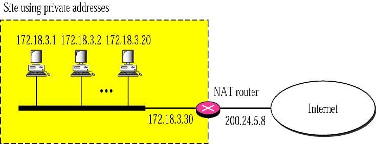

28 Address translation 28
29 DHCP (Dynamic Host Configuration Protocol) DHCP protocol is used to assign IP addresses to hosts or workstations on the network. Usually a DHCP server on the network performs this function. Basically it "leases" out address for specific times to the various hosts. If a host does not use a given address for some period of time, that IP address can then be assigned to another machine by the DHCP server. When assignments are made or changed, the DHCP server must update the information in the DNS server. As with BOOTP, DHCP uses the machine's or NIC ethernet (MAC) or hardware address to determine IP address assignments. The DHCP protocol is built on BOOTP and replaces BOOTP. DHCP Lease Stages 1. Lease Request - The client sends a broadcast requesting an IP address 2. Lease Offer - The server sends the above information and marks the offered address as unavailable. The message sent is a DHCPOFFER broadcast message. 3. Lease Acceptance - The first offer received by the client is accepted. The acceptance is sent from the client as a broadcast (DHCPREQUEST message) including the IP address of the DNS server that sent the accepted offer. Other DHCP servers retract their offers and mark the offered address as available and the accepted address as unavailable. 4. Server lease acknowledgement - The server sends a DHCPACK or a DHCPNACK if an unavailable address was requested. DHCP discover message - The initial broadcast sent by the client to obtain a DHCP lease. It contains the client MAC address and computer name. This is a broadcast using as the destination address and as the source address. Dynamic Host Configuration Protocol (DHCP) is a network protocol that enables a server to automatically assign an IP address to a computer from a defined range of numbers (i.e., a scope) configured for a given network. DHCP assigns an IP address when a system is started, for example: 1. A user turns on a computer with a DHCP client. 2. The client computer sends a broadcast request (called a DISCOVER or DHCPDISCOVER), looking for a DHCP server to answer. 3. The router directs the DISCOVER packet to the correct DHCP server. 4. The server receives the DISCOVER packet. Based on availability and usage policies set on the server, the server determines an appropriate address (if any) to give to the client. The server then temporarily reserves that address for the client and sends back to the client an OFFER (or DHCPOFFER) packet, with that address information. The server also configures the client's DNS servers, WINS servers, NTP servers, and sometimes other services as well. 5. The client sends a REQUEST (or DHCPREQUEST) packet, letting the server know that it intends to use the address. 29
30 6. The server sends an ACK (or DHCPACK) packet, confirming that the client has a been given a lease on the address for a server-specified period of time. When a computer uses a static IP address, it means that the computer is manually configured to use a specific IP address. One problem with static assignment, which can result from user error or inattention to detail, occurs when two computers are configured with the same IP address. This creates a conflict that results in loss of service. Using DHCP to dynamically assign IP addresses minimizes these conflicts. Figure 1 In figure 1, a new client that just joined the network, needs an IP address. Since it does not know the DHCP server's location, the client broadcasts (step 1) a DHCPDISCOVER message on the local network. The message packet contains a hardware identifier (usually the MAC address), the source port (68), the destination IP ( ), destination port (67), and a randomly generated transaction id. Optionally the client can specify the IP address it wants and the lease duration in the message. Once the DHCP relay receives the broadcasted message, it fills in the "giaddr" field of the packet with the gateway IP address of This piece of information is critical because the DHCP Server needs it to determine which subnet the client is on and thus which IP address to allocate to the client. Afterwards the DHCPDISCOVER message is relayed to the DHCP Server via unicast (step 2). A unicast, instead of a broadcast, is sufficient because the DHCP relay knows the exact location of the DHCP server. For this same reason, the DHCP relay does not allow the other network segment, X, to receive the message. Once the DHCP server receives the DHCPDISCOVER request, it allocates an IP address, marks it as taken, and then broadcasts a DHCPOFFER message back to the requesting client. This message packet contains the DHCP server's IP address, the client's hardware identifier, the same transaction id, and the IP address allocated for the client. Optionally, the message 30
31 may also contain the lease time, subnet mask, default TTL, default router(s), and numerous other parameters. Figure 2 In figure 2, the DHCP server allocates new IP address for the client and broadcasts a DHCPOFFER message to its network (step 3). When the DHCP relay sees the DHCPOFFER broadcast, it relays the broadcast to the X network and only that network (step 4). Once the new client sees the DHCPOFFER message, it accepts the IP address (step 5) and prepares a confirmation message to the DHCP server with a DHCPREQUEST packet. Please note that the client does not have to accept this IP address, in which case it will not send a DHCPREQUEST message. If multiple DHCP servers sends out a DHCPOFFER, the client can choose which one to accept. If for some reason, the DHCPOFFER message fails to ever arrive, the client will rebroadcast the DHCPDISCOVER message. Figure 3 31
32 If the client included optional information in the initial DHCPDISCOVER message, it must include that same information in the subsequent DHCPREQUEST message. In step 6 of figure 3, the new client confirms it wants the IP address by broadcasting a DHCPREQUEST to the DHCP server. Once the DHCP Server receives this message (with help again from the DHCP Relay), it first ensures that it is the intended target - because the client could be responding to another DHCP Server. If this DHCP server is not the intended target, then it knows some other DHCP server is handling this client. So this DHCP server can discard any previously allocated IP address for that client. If this DHCP Server is the intended recipient, then it has to verify the optional parameters that it specified in the previous DHCPOFFER message to this client, are still valid. Assuming everything is fine up to this point, the DHCP Server sends a DHCPACK broadcast (step 8) to tell the client that its new IP address can now officially be used. However, if something is wrong, then a DHCPNACK is broadcasted instead. Either way, a DHCPACK or DHCPNACK will be the final message sent by the DHCP server in the dynamic IP address allocation sequence.. Assuming it receives the DHCPACK relayed by the router (step 9), the client is encouraged to verify no other hosts has the same IP address. This is usually accomplished through a simple ARP probe. Any response to the probe means that another client is already using the IP address. In such a situation, the client must send a DHCPDECLINE message to the DHCP server. Afterwards the client will then need to restart this whole process beginning with DHCPDISCOVER phase. In most cases, there's no response to the client's ARP probe. This means the client can go ahead and use the allocated IP address along with any other optional information stored in the message packet. If the client got a DHCPNAK instead of DHCPACK, then it has no choice but to restart everything from the very beginning i.e. the DHCPDISCOVER stage. Finally, if the client doesn't receive any DHCPACK or DHCPNAK message after a certain period of time, then it rebroadcasts the DHCPREQUEST message. 32
UNIT IV- TCP/IP-II. Transport Control Protocol (TCP) Port addresses
 Port addresses") UNIT IV- TCP/IP-II Transport Control Protocol (TCP) TCP is a connection oriented, reliable protocol used in internet to provide a reliable endto-end byte stream over an unreliable internetwork (IP) An
UNIT IV- TCP/IP-II Transport Control Protocol (TCP) TCP is a connection oriented, reliable protocol used in internet to provide a reliable endto-end byte stream over an unreliable internetwork (IP) An
Topics for This Week
 Topics for This Week Routing Protocols in the Internet OSPF, BGP More on IP Fragmentation and Reassembly ICMP Readings Sections 5.6.4-5.6.5 1 Hierarchical Routing aggregate routers into regions, autonomous
Unit 3: Dynamic Routing
 Unit 3: Dynamic Routing Basic Routing The term routing refers to taking a packet from one device and sending it through the network to another device on a different network. Routers don t really care about
Basic Idea. Routing. Example. Routing by the Network
 Basic Idea Routing Routing table at each router/gateway When IP packet comes, destination address checked with routing table to find next hop address Questions: Route by host or by network? Routing table:
Last time. Transitioning to IPv6. Routing. Tunneling. Gateways. Graph abstraction. Link-state routing. Distance-vector routing. Dijkstra's Algorithm
 Last time Transitioning to IPv6 Tunneling Gateways Routing Graph abstraction Link-state routing Dijkstra's Algorithm Distance-vector routing Bellman-Ford Equation 10-1 This time Distance vector link cost
Routing by the Network
 Routing Basic Idea Routing table at each router/gateway When IP packet comes, destination address checked with routing table to find next hop address Questions: Route by host or by network? Routing table:
Da t e: August 2 0 th a t 9: :00 SOLUTIONS
 Interne t working, Examina tion 2G1 3 0 5 Da t e: August 2 0 th 2 0 0 3 a t 9: 0 0 1 3:00 SOLUTIONS 1. General (5p) a) Place each of the following protocols in the correct TCP/IP layer (Application, Transport,
Routing in the Internet
 Routing in the Internet Daniel Zappala CS 460 Computer Networking Brigham Young University Scaling Routing for the Internet 2/29 scale 200 million destinations - can t store all destinations or all prefixes
EEC-684/584 Computer Networks
 EEC-684/584 Computer Networks Lecture 14 wenbing@ieee.org (Lecture nodes are based on materials supplied by Dr. Louise Moser at UCSB and Prentice-Hall) Outline 2 Review of last lecture Internetworking
UNIT IV TCP, UNICAST AND MULTICAST ROUTING PROTOCOLS
 UNIT IV TCP, UNICAST AND MULTICAST ROUTING PROTOCOLS Services flow, congestion and error control TCP package and operation state transition diagram unicast routing protocols RIP OSPF BGP multicast routing
Why multicast? The concept of multicast Multicast groups Multicast addressing Multicast routing protocols MBONE Multicast applications Conclusions
 Tuomo Karhapää tuomo.karhapaa@otaverkko.fi Otaverkko Oy Why multicast? The concept of multicast Multicast groups Multicast addressing Multicast routing protocols MBONE Multicast applications Conclusions
EEC-682/782 Computer Networks I
 EEC-682/782 Computer Networks I Lecture 15 Wenbing Zhao w.zhao1@csuohio.edu http://academic.csuohio.edu/zhao_w/teaching/eec682.htm (Lecture nodes are based on materials supplied by Dr. Louise Moser at
Top-Down Network Design
 Top-Down Network Design Chapter Seven Selecting Switching and Routing Protocols Original slides by Cisco Press & Priscilla Oppenheimer Selection Criteria for Switching and Routing Protocols Network traffic
EECS 122, Lecture 16. Link Costs and Metrics. Traffic-Sensitive Metrics. Traffic-Sensitive Metrics. Static Cost Metrics.
 EECS 122, Lecture 16 Kevin Fall kfall@cs.berkeley.edu edu Link Costs and Metrics Routing protocols compute shortest/cheapest paths using some optimization criteria Choice of criteria has strong effect
Routing Protocols. Autonomous System (AS)
") Routing Protocols Two classes of protocols: 1. Interior Routing Information Protocol (RIP) Open Shortest Path First (OSPF) 2. Exterior Border Gateway Protocol (BGP) Autonomous System (AS) What is an AS?
Routing Protocols Two classes of protocols: 1. Interior Routing Information Protocol (RIP) Open Shortest Path First (OSPF) 2. Exterior Border Gateway Protocol (BGP) Autonomous System (AS) What is an AS?
Top-Down Network Design, Ch. 7: Selecting Switching and Routing Protocols. Top-Down Network Design. Selecting Switching and Routing Protocols
 Top-Down Network Design Chapter Seven Selecting Switching and Routing Protocols Copyright 2010 Cisco Press & Priscilla Oppenheimer 1 Switching 2 Page 1 Objectives MAC address table Describe the features
Internet Routing Protocols, DHCP, and NAT
 Internet Routing Protocols, DHCP, and NAT Hwajung Lee Modified from Slides Courtesy of Cisco Networking Academy and the book titled Communication Networks by Leon-Garcia Contents Basic Routing Single Area
TDC 363 Introduction to LANs
 TDC 363 Introduction to LANs Routing Protocols and RIP Greg Brewster DePaul University TDC 363 1 Dynamic Routing Routing Protocols Distance Vector vs. Link State Protocols RIPv1 & RIPv2 RIP Problems Slow
Routing Protocols. The routers in an internet are responsible for receiving and. forwarding IP datagrams through the interconnected set of
 Routing Protocols MITA DUTTA The routers in an internet are responsible for receiving and forwarding IP datagrams through the interconnected set of sub-networks from source to destination. Routing protocols
Hierarchical Routing. Our routing study thus far - idealization all routers identical network flat not true in practice
 Hierarchical Routing Our routing study thus far - idealization all routers identical network flat not true in practice scale: with 200 million destinations: can t store all destinations in routing tables!
Chapter 4: outline. Network Layer 4-1
 Chapter 4: outline 4.1 introduction 4.2 virtual circuit and datagram networks 4.3 what s inside a router 4.4 IP: Internet Protocol datagram format IPv4 addressing ICMP IPv6 4.5 routing algorithms link
CSc 450/550 Computer Networks Internet Routing
 CSc 450/550 Computer Networks Internet Routing Jianping Pan Summer 2007 7/12/07 CSc 450/550 1 Review Internet Protocol (IP) IP header addressing class-based, classless, hierarchical, NAT routing algorithms
CSC 4900 Computer Networks: Routing Protocols
 CSC 4900 Computer Networks: Routing Protocols Professor Henry Carter Fall 2017 Last Time Link State (LS) versus Distance Vector (DV) algorithms: What are some of the differences? What is an AS? Why do
ETSF10 Internet Protocols Routing on the Internet
 ETSF10 Internet Protocols Routing on the Internet 2014, Part 2, Lecture 1.2 Jens Andersson Internet Hierarchy 2014-11-10 ETSF05/ETSF05/ETSF10 - Internet Protocols 2 Hierarchical Routing aggregate routers
Chapter 4: Network Layer
 Chapter 4: Network Layer 4. 1 Introduction 4.2 Virtual circuit and datagram networks 4.3 What s inside a router 4.4 IP: Internet Protocol Datagram format IPv4 addressing ICMP IPv6 4.5 Routing algorithms
Announcements. CS 5565 Network Architecture and Protocols. Project 2B. Project 2B. Project 2B: Under the hood. Routing Algorithms
 Announcements CS 5565 Network Architecture and Protocols Lecture 20 Godmar Back Project 2B due in 2 parts: Apr 29 and May 6 Extra Credit Opportunities: Expand simulator (and your implementation) to introduce
ITEC310 Computer Networks II
 ITEC310 Computer Networks II Chapter 22 Network Layer:, and Routing Department of Information Technology Eastern Mediterranean University Objectives 2/131 After completing this chapter you should be able
Building the Routing Table. Introducing the Routing Table Directly Connected Networks Static Routing Dynamic Routing Routing Table Principles
 Building the Routing Table Introducing the Routing Table Directly Connected Networks Static Routing Dynamic Routing Routing Table Principles Introducing the Routing Table R1# show ip route Codes: C - connected,
Computer Networking Introduction
 Computer Networking Introduction Halgurd S. Maghdid Software Engineering Department Koya University-Koya, Kurdistan-Iraq Lecture No.15 Chapter 4: outline 4.1 introduction 4.2 virtual circuit and datagram
9.1. Routing Protocols
 9.1. Routing Protocols Each organization that has been assigned a network address from an ISP is considered an autonomous system (AS). That organization is free to create one large network, or divide the
User Datagram Protocol
 Topics Transport Layer TCP s three-way handshake TCP s connection termination sequence TCP s TIME_WAIT state TCP and UDP buffering by the socket layer 2 Introduction UDP is a simple, unreliable datagram
Chapter 2 - Part 1. The TCP/IP Protocol: The Language of the Internet
 Chapter 2 - Part 1 The TCP/IP Protocol: The Language of the Internet Protocols A protocol is a language or set of rules that two or more computers use to communicate 2 Protocol Analogy: Phone Call Parties
Dongsoo S. Kim Electrical and Computer Engineering Indiana U. Purdue U. Indianapolis
 Session 8. TCP/IP Dongsoo S. Kim (dskim@iupui.edu) Electrical and Computer Engineering Indiana U. Purdue U. Indianapolis IP Packet 0 4 8 16 19 31 Version IHL Type of Service Total Length Identification
Network Layer: Routing
 Network Layer: Routing The Problem A B R 1 R 2 R 4 R 3 Goal: for each destination, compute next hop 1 Lecture 9 2 Basic Assumptions Trivial solution: Flooding Dynamic environment: links and routers unreliable:
Chapter 12 Network Protocols
 Chapter 12 Network Protocols 1 Outline Protocol: Set of defined rules to allow communication between entities Open Systems Interconnection (OSI) Transmission Control Protocol/Internetworking Protocol (TCP/IP)
What is the difference between unicast and multicast? (P# 114)
") 1 FINAL TERM FALL2011 (eagle_eye) CS610 current final term subjective all solved data by eagle_eye MY paper of CS610 COPUTER NETWORKS There were 30 MCQs Question no. 31 (Marks2) Find the class in 00000001.001011.1001.111
1 FINAL TERM FALL2011 (eagle_eye) CS610 current final term subjective all solved data by eagle_eye MY paper of CS610 COPUTER NETWORKS There were 30 MCQs Question no. 31 (Marks2) Find the class in 00000001.001011.1001.111
Lecture 12. Introduction to IP Routing. Why introduction? Routing
 Lecture. Introduction to IP Routing Why introduction? Routing: very complex issue need in-depth study entire books on routing our scope: give a flavour of basic routing structure and messaging give an
Multicast Communications. Slide Set were original prepared by Dr. Tatsuya Susa
 Multicast Communications Slide Set were original prepared by Dr. Tatsuya Susa Outline 1. Advantages of multicast 2. Multicast addressing 3. Multicast Routing Protocols 4. Multicast in the Internet 5. IGMP
MULTICAST EXTENSIONS TO OSPF (MOSPF)
") MULTICAST EXTENSIONS TO OSPF (MOSPF) Version 2 of the Open Shortest Path First (OSPF) routing protocol is defined in RFC-1583. It is an Interior Gateway Protocol (IGP) specifically designed to distribute
MULTICAST EXTENSIONS TO OSPF (MOSPF) Version 2 of the Open Shortest Path First (OSPF) routing protocol is defined in RFC-1583. It is an Interior Gateway Protocol (IGP) specifically designed to distribute
Chapter 09 Network Protocols
 Chapter 09 Network Protocols Copyright 2011, Dr. Dharma P. Agrawal and Dr. Qing-An Zeng. All rights reserved. 1 Outline Protocol: Set of defined rules to allow communication between entities Open Systems
Table of Contents. Cisco Introduction to EIGRP
 Table of Contents Introduction to EIGRP...1 Introduction...1 Before You Begin...1 Conventions...1 Prerequisites...1 Components Used...1 What is IGRP?...2 What is EIGRP?...2 How Does EIGRP Work?...2 EIGRP
Chapter 4: Network Layer. Lecture 12 Internet Routing Protocols. Chapter goals: understand principles behind network layer services:
 NET 331 Computer Networks Lecture 12 Internet Routing Protocols Dr. Anis Koubaa Reformatted slides from textbook Computer Networking a top-down appraoch, Fifth Edition by Kurose and Ross, (c) Pearson Education
Table of Contents 1 Static Routing Configuration RIP Configuration 2-1
 Table of Contents 1 Static Routing Configuration 1-1 Introduction 1-1 Static Route 1-1 Default Route 1-1 Application Environment of Static Routing 1-1 Configuring a Static Route 1-2 Configuration Prerequisites
II. Principles of Computer Communications Network and Transport Layer
 II. Principles of Computer Communications Network and Transport Layer A. Internet Protocol (IP) IPv4 Header An IP datagram consists of a header part and a text part. The header has a 20-byte fixed part
Chapter 7: Routing Dynamically. Routing & Switching
 Chapter 7: Routing Dynamically Routing & Switching The Evolution of Dynamic Routing Protocols Dynamic routing protocols used in networks since the late 1980s Newer versions support the communication based
ETSF10 Internet Protocols Routing on the Internet
 ETSF10 Internet Protocols Routing on the Internet 2013, Part 2, Lecture 1.2 Jens Andersson (Kaan Bür) Routing on the Internet Unicast routing protocols (part 2) [ed.5 ch.20.3] Multicast routing, IGMP [ed.5
CS 356: Computer Network Architectures. Lecture 14: Switching hardware, IP auxiliary functions, and midterm review. [PD] chapter 3.4.1, 3.2.
![CS 356: Computer Network Architectures. Lecture 14: Switching hardware, IP auxiliary functions, and midterm review. [PD] chapter 3.4.1, 3.2.](/thumbs/85/92708725.jpg "CS 356: Computer Network Architectures. Lecture 14: Switching hardware, IP auxiliary functions, and midterm review. [PD] chapter 3.4.1, 3.2.") CS 356: Computer Network Architectures Lecture 14: Switching hardware, IP auxiliary functions, and midterm review [PD] chapter 3.4.1, 3.2.7 Xiaowei Yang xwy@cs.duke.edu Switching hardware Software switch
CS 356: Computer Network Architectures Lecture 14: Switching hardware, IP auxiliary functions, and midterm review [PD] chapter 3.4.1, 3.2.7 Xiaowei Yang xwy@cs.duke.edu Switching hardware Software switch
CS555, Spring /5/2005. April 12, 2005 No classes attend Senior Design Projects conference. Chapter 4 roadmap. Internet AS Hierarchy
 CS555, Spring 2005 April 12, 2005 No classes attend Senior Design Projects conference Network Layer 4-1 Chapter 4 roadmap 4.1 Introduction and Network Service Models 4.2 VC and Datagram Networks 4.3 What
debug ip ospf database external default-metric subnet area 0 stub distribute-list in Serial0/1
 Which statement about stateless autoconfiguration is true? A host can autoconfigure itself by appending its MAC address to the local link prefix (64 bits). 2 Autoconfiguration allows devices to connect
Examination 2D1392 Protocols and Principles of the Internet 2G1305 Internetworking 2G1507 Kommunikationssystem, fk SOLUTIONS
 Examination 2D1392 Protocols and Principles of the Internet 2G1305 Internetworking 2G1507 Kommunikationssystem, fk Date: January 17 th 2006 at 14:00 18:00 SOLUTIONS 1. General (5p) a) Draw the layered
IP Multicast Technology Overview
 IP multicast is a bandwidth-conserving technology that reduces traffic by delivering a single stream of information simultaneously to potentially thousands of businesses and homes. Applications that take
Chapter IV: Network Layer
 Chapter IV: Network Layer UG3 Computer Communications & Networks (COMN) Myungjin Lee myungjin.lee@ed.ac.uk Slides copyright of Kurose and Ross Hierarchical routing our routing study thus far - idealization
DATA COMMUNICATOIN NETWORKING
 DATA COMMUNICATOIN NETWORKING Instructor: Ouldooz Baghban Karimi Course Book & Slides: Computer Networking, A Top-Down Approach By: Kurose, Ross Introduction Course Overview Basics of Computer Networks
What is Multicasting? Multicasting Fundamentals. Unicast Transmission. Agenda. L70 - Multicasting Fundamentals. L70 - Multicasting Fundamentals
 What is Multicasting? Multicasting Fundamentals Unicast transmission transmitting a packet to one receiver point-to-point transmission used by most applications today Multicast transmission transmitting
Open Shortest Path First (OSPF)
") CHAPTER 42 Open Shortest Path First (OSPF) Background Open Shortest Path First (OSPF) is a routing protocol developed for Internet Protocol (IP) networks by the interior gateway protocol (IGP) working
CHAPTER 42 Open Shortest Path First (OSPF) Background Open Shortest Path First (OSPF) is a routing protocol developed for Internet Protocol (IP) networks by the interior gateway protocol (IGP) working
Why dynamic route? (1)
") Routing Why dynamic route? (1) Static route is ok only when Network is small There is a single connection point to other network No redundant route 2 Why dynamic route? (2) Dynamic Routing Routers update
Routing Why dynamic route? (1) Static route is ok only when Network is small There is a single connection point to other network No redundant route 2 Why dynamic route? (2) Dynamic Routing Routers update
HY 335 Φροντιστήριο 8 ο
 HY 335 Φροντιστήριο 8 ο Χειμερινό Εξάμηνο 2009-2010 Παπακωνσταντίνου Άρτεμις artpap@csd.uoc.gr 4/12/2009 Roadmap IP: The Internet Protocol IPv4 Addressing Datagram Format Transporting a datagram from source
Chapter 7 Routing Protocols
 Chapter 7 Routing Protocols Nonroutable Protocols In the early days of networking, networks were small collections of computers linked together For the purposes of sharing information and expensive peripherals
Network Routing. Packet Routing, Routing Algorithms, Routers, Router Architecture
 Network Routing Packet Routing, Routing Algorithms, Routers, Router Architecture Routing Routing protocol Goal: determine good path (sequence of routers) thru network from source to dest. Graph abstraction
Internet Routing Protocols Tuba Saltürk
 Internet Routing Protocols 15505068 Tuba Saltürk Outline Internet Routers Routing Protocol Interior Gateway Protocol (IGP) Distance- Vector Routing Protocol Routing Information Protocol (RIP) Interior
ETSF05/ETSF10 Internet Protocols. Routing on the Internet
 ETSF05/ETSF10 Internet Protocols Routing on the Internet Circuit switched routing ETSF05/ETSF10 - Internet Protocols 2 Routing in Packet Switching Networks Key design issue for (packet) switched networks
Inter-Domain Routing: BGP
 Inter-Domain Routing: BGP Richard T. B. Ma School of Computing National University of Singapore CS 3103: Compute Networks and Protocols Inter-Domain Routing Internet is a network of networks Hierarchy
Overview 4.2: Routing
 Overview 4.2: Routing Forwarding vs Routing forwarding: to select an output port based on destination address and routing table routing: process by which routing table is built Network as a Graph A 6 1
Internet Interconnection Structure
 Internet Interconnection Structure Basic Concepts (1) Internet Service Provider (ISP) Provider who connects an end user customer with the Internet in one or few geographic regions. National & Regional
RIP Version 2. The Classless Brother
 RIP Version 2 The Classless Brother (C) Herbert Haas 2005/03/11 1 Why RIPv2 Need for subnet information and VLSM Need for Next Hop addresses for each route entry Need for external route tags Need for multicast
Internet Protocol: Routing Algorithms. Srinidhi Varadarajan
 Internet Protocol: Routing Algorithms Srinidhi Varadarajan Routing Routing protocol Goal: determine good path (sequence of routers) thru network from source to dest. Graph abstraction for routing algorithms:
TCP/IP Networking. Part 4: Network and Transport Layer Protocols
 TCP/IP Networking Part 4: Network and Transport Layer Protocols Orientation Application Application protocol Application TCP TCP protocol TCP IP IP protocol IP IP protocol IP IP protocol IP Network Access
Routing Protocols --- Exterior Gateway Protocol
 Content Routing Protocols --- Exterior Gateway Protocol Linda Wu (CMPT 471 23-3) Limiting router interaction Autonomous system BGP protocol BGP messages Other issues on BGP Reference: chapter 15 Notes-13
Routing, Routing Algorithms & Protocols
 Routing, Routing Algorithms & Protocols Computer Networks Lecture 6 http://goo.gl/pze5o8 Circuit-Switched and Packet-Switched WANs 2 Circuit-Switched Networks Older (evolved from telephone networks), a
CSCE 463/612 Networks and Distributed Processing Spring 2018
 CSCE 463/612 Networks and Distributed Processing Spring 2018 Network Layer IV Dmitri Loguinov Texas A&M University April 12, 2018 Original slides copyright 1996-2004 J.F Kurose and K.W. Ross 1 Chapter
CS118 Discussion Week 7. Taqi
 CS118 Discussion Week 7 Taqi Outline Hints for project 2 Lecture review: routing About Course Project 2 Please implement byte-stream reliable data transfer Cwnd is in unit of bytes, not packets How to
Chapter 4: Network Layer, partb
 Chapter 4: Network Layer, partb The slides are adaptations of the slides available by the main textbook authors, Kurose&Ross Network Layer 4-1 Interplay between routing, forwarding routing algorithm local
Politecnico di Milano Scuola di Ingegneria Industriale e dell Informazione. 06 Routing protocols. Fundamentals of Communication Networks
 Politecnico di Milano Scuola di Ingegneria Industriale e dell Informazione 06 Routing protocols Fundamentals of Communication Networks Topics o Routing basics o Routing algorithms (Bellman-Ford, Dijkstra)
Lab 4: Routing using OSPF
 Network Topology:- Lab 4: Routing using OSPF Device Interface IP Address Subnet Mask Gateway/Clock Description Rate Fa 0/0 172.16.1.17 255.255.255.240 ----- R1 LAN R1 Se 0/0/0 192.168.10.1 255.255.255.252
CSCI Topics: Internet Programming Fall 2008
 CSCI 491-01 Topics: Internet Programming Fall 2008 Network Layer Derek Leonard Hendrix College November 17, 2008 Original slides copyright 1996-2007 J.F Kurose and K.W. Ross 1 Chapter 4: Roadmap 4.1 Introduction
Chapter 19 Network Layer: Logical Addressing
 Chapter 19 Network Layer: Logical Addressing 19.1 Copyright The McGraw-Hill Companies, Inc. Permission required for reproduction or display. 19.2 19-1 IPv4 ADDRESSES An IPv4 address is a 32-bit address
Lecture 19: Network Layer Routing in the Internet
 Lecture 19: Network Layer Routing in the Internet COMP 332, Spring 2018 Victoria Manfredi Acknowledgements: materials adapted from Computer Networking: A Top Down Approach 7 th edition: 1996-2016, J.F
Internet Routing : Fundamentals of Computer Networks Bill Nace
 Internet Routing 14-740: Fundamentals of Computer Networks Bill Nace Material from Computer Networking: A Top Down Approach, 6 th edition. J.F. Kurose and K.W. Ross Looking Ahead Lab #2 just due Quiz #2
Chapter 4: Advanced Internetworking. Networking CS 3470, Section 1
 Chapter 4: Advanced Internetworking Networking CS 3470, Section 1 Intra-AS and Inter-AS Routing a C C.b b d A A.a a b A.c c B.a a B c Gateways: perform inter-as routing amongst themselves b perform intra-as
Initial motivation: 32-bit address space soon to be completely allocated. Additional motivation:
 IPv6 Initial motivation: 32-bit address space soon to be completely allocated. Additional motivation: header format helps speed processing/forwarding header changes to facilitate QoS IPv6 datagram format:
Routing Protocol Type Primarily IGP or EGP RIP Distance-Vector IGP EIGRP OSPF IS-IS BGP
 Appendix D Memory Tables Chapter 1 Table 1-2 Routing Protocol Characteristics Routing Protocol Type Primarily IGP or EGP RIP Distance-Vector IGP EIGRP OSPF IS-IS BGP Chapter 3 Table 3-2 Hexadecimal/Binary
Table of Contents 1 OSPF Configuration 1-1
 Table of Contents 1 OSPF Configuration 1-1 Introduction to OSPF 1-1 Basic Concepts 1-2 OSPF Area Partition 1-4 Router Types 1-7 Classification of OSPF Networks 1-9 DR and BDR 1-9 OSPF Packet Formats 1-11
User Datagram Protocol (UDP):
:") SFWR 4C03: Computer Networks and Computer Security Feb 2-5 2004 Lecturer: Kartik Krishnan Lectures 13-15 User Datagram Protocol (UDP): UDP is a connectionless transport layer protocol: each output operation
SFWR 4C03: Computer Networks and Computer Security Feb 2-5 2004 Lecturer: Kartik Krishnan Lectures 13-15 User Datagram Protocol (UDP): UDP is a connectionless transport layer protocol: each output operation
Routing Between Autonomous Systems (Example: BGP4) RFC 1771
 RFC 1771") CS 4/55231 Internet Engineering Kent State University Dept. of Computer Science LECT-7B Routing Between Autonomous Systems (Example: BGP4) RFC 1771 52 53 BGP4 Overview Example of Operations BGP4 is a path
CS 4/55231 Internet Engineering Kent State University Dept. of Computer Science LECT-7B Routing Between Autonomous Systems (Example: BGP4) RFC 1771 52 53 BGP4 Overview Example of Operations BGP4 is a path
ETSF05/ETSF10 Internet Protocols Routing on the Internet
 ETSF05/ETSF10 Internet Protocols Routing on the Internet 2014, (ETSF05 Part 2), Lecture 1.1 Jens Andersson Circuit switched routing 2014 11 05 ETSF05/ETSF10 Internet Protocols 2 Packet switched Routing
CCNA 3 (v v6.0) Chapter 5 Exam Answers % Full
 Chapter 5 Exam Answers % Full") CCNA 3 (v5.0.3 + v6.0) Chapter 5 Exam Answers 2017 100% Full ccnav6.com /ccna-3-v5-0-3-v6-0-chapter-5-exam-answers-2017-100-full.html CCNA Exam Answers 2017 CCNA 3 (v5.0.3 + v6.0) Chapter 5 Exam Answers
CCNA 3 (v5.0.3 + v6.0) Chapter 5 Exam Answers 2017 100% Full ccnav6.com /ccna-3-v5-0-3-v6-0-chapter-5-exam-answers-2017-100-full.html CCNA Exam Answers 2017 CCNA 3 (v5.0.3 + v6.0) Chapter 5 Exam Answers
Routing Unicast routing protocols
 Routing Unicast routing protocols Jens A Andersson Electrical and Information Technology R1 Choosing an Optimal Path R4 5 R7 5 10 40 R6 6 5 B R2 15 A 20 4 10 10 R8 R3 5 10 R5 1 Router A router is a type
IP Addressing & Interdomain Routing. Next Topic
 IP Addressing & Interdomain Routing Next Topic IP Addressing Hierarchy (prefixes, class A, B, C, subnets) Interdomain routing Application Presentation Session Transport Network Data Link Physical Scalability
Inter-networking. Problem. 3&4-Internetworking.key - September 20, LAN s are great but. We want to connect them together. ...
 1 Inter-networking COS 460 & 540 2 Problem 3 LAN s are great but We want to connect them together...across the world Inter-networking 4 Internet Protocol (IP) Routing The Internet Multicast* Multi-protocol
Inter-AS routing. Computer Networking: A Top Down Approach 6 th edition Jim Kurose, Keith Ross Addison-Wesley
 Inter-AS routing Computer Networking: A Top Down Approach 6 th edition Jim Kurose, Keith Ross Addison-Wesley Some materials copyright 1996-2012 J.F Kurose and K.W. Ross, All Rights Reserved Chapter 4:
Operation Manual IPv4 Routing H3C S3610&S5510 Series Ethernet Switches. Table of Contents
 Table of Contents Table of Contents Chapter 1 Static Routing Configuration... 1-1 1.1 Introduction... 1-1 1.1.1 Static Route... 1-1 1.1.2 Default Route... 1-1 1.1.3 Application Environment of Static Routing...
Operation Manual DHCP. Table of Contents
 Table of Contents Table of Contents Chapter 1 DHCP Overview... 1-1 1.1 DHCP Principles... 1-1 1.1.1 BOOTP Relay Agent... 1-3 1.1.2 DHCP and BOOTP Relay Agent... 1-4 1.2 General DHCP Configuration... 1-4
Internetworking Part 2
 CMPE 344 Computer Networks Spring 2012 Internetworking Part 2 Reading: Peterson and Davie, 3.2, 4.1 19/04/2012 1 Aim and Problems Aim: Build networks connecting millions of users around the globe spanning
Routing. Jens A Andersson Communication Systems
 Routing Jens A Andersson Communication Systems R1 Choosing an Optimal Path R4 5 R7 5 10 40 R6 6 5 B R2 15 A 20 4 10 10 R8 R3 5 R5 10 Router A router is a type of internetworking device that passes data
Introduction to Routing
 1 Introduction to Routing Session 2 Presentation_ID.scr 1 Agenda Addressing Concepts Routing Protocols Statics and Defaults 3 ISO OSI Reference Model Routing Information Protocol (RIP and RIPv2) L7 L6
Acknowledgments. Part One - Introduction to the TCP/IP Protocol
 Illustrated TCP/IP by Matthew G. Naugle Wiley Computer Publishing, John Wiley & Sons, Inc. ISBN: 0471196568 Pub Date: 11/01/98 Acknowledgments Part One - Introduction to the TCP/IP Protocol Chapter 1 -
Overview. Problem: Find lowest cost path between two nodes Factors static: topology dynamic: load
 Dynamic Routing Overview Forwarding vs Routing forwarding: to select an output port based on destination address and routing table routing: process by which routing table is built Network as a Graph C
CS 43: Computer Networks. 24: Internet Routing November 19, 2018
 CS 43: Computer Networks 24: Internet Routing November 19, 2018 Last Class Link State + Fast convergence (reacts to events quickly) + Small window of inconsistency Distance Vector + + Distributed (small
Telecommunication Protocols Laboratory Course. Lecture 3
 Telecommunication Protocols Laboratory Course Lecture 3 Course map Last time: we discussed protocols of the Medium Access Control (MAC) sub-layer Deal with broadcast channels and their (multi-party) protocols
Border Gateway Protocol (BGP-4)
") Vanguard Applications Ware IP and LAN Feature Protocols Border Gateway Protocol (BGP-4) Notice 2008 Vanguard Networks 25 Forbes Blvd Foxboro, MA 02035 Phone: (508) 964 6200 Fax: (508) 543 0237 All rights
Vanguard Applications Ware IP and LAN Feature Protocols Border Gateway Protocol (BGP-4) Notice 2008 Vanguard Networks 25 Forbes Blvd Foxboro, MA 02035 Phone: (508) 964 6200 Fax: (508) 543 0237 All rights