MICRO 3 C PLC User s Manual
|
|
|
- Carol Chambers
- 6 years ago
- Views:
Transcription


1 MICRO 3 C PLC User s Manual
2 SAFETY PRECAUTIONS Read this user s manual to make sure of correct operation before starting installation, wiring, operation, maintenance, and inspection of the MICRO 3 C. All MICRO 3 C s are manufactured under IDEC s rigorous quality control system, but users must add a backup or failsafe provision to the control system using the MICRO 3 C in applications where heavy damage or personal injury may be caused in case the MICRO 3 C should fail. In this user s manual, safety precautions are categorized in order of importance to Warning and Caution: Warning Caution Warning notices are used to emphasize that improper operation may cause severe personal injury or death. Caution notices are used where inattention might cause personal injury or damage to equipment. Warning Turn power off to the MICRO 3 C before starting installation, removal, wiring, maintenance, and inspection on the MICRO 3 C. Failure to turn power off may cause electrical shocks or fire hazard. Special expertise is required to install, wire, program, and operate the MICRO 3 C. People without such expertise must not use the MICRO 3 C. Emergency and interlocking circuits must be configured outside the MICRO 3 C. If such a circuit is configured inside the MICRO 3 C, failure of the MICRO 3 C may cause disorder of the control system, damage, or accidents. Caution Install the MICRO 3 C according to instructions described in this user s manual and the MICRO 3 user s manual. Improper installation will result in falling, failure, or malfunction of the MICRO 3 C. MICRO 3 C is designed for installation in equipment. Do not install the MICRO 3 C outside of equipment. Install the MICRO 3 C in environments described in this user s manual and the MICRO 3 user s manual. If the MICRO 3 C is used in places where the MICRO 3 C is subjected to high-temperature, high-humidity, condensation, corrosive gases, excessive vibrations, and excessive shocks, then electrical shocks, fire hazard, or malfunction will result. MICRO 3 C is designed for use in Pollution degree 2. Use the MICRO 3 C in environments of pollution degree 2 (according to IEC664-1). All DC power type MICRO 3 C units are PS2 type (according to EN61131). Prevent the MICRO 3 C from falling while moving or transporting the MICRO 3 C, otherwise damage or malfunction of the MICRO 3 C will result. Prevent metal fragments and pieces of wire from dropping inside the MICRO 3 C housing. Put a cover on the MICRO 3 C during installation and wiring. Ingress of such fragments and chips may cause fire hazard, damage, or malfunction. Use a power supply of the rated value. Use of a wrong power supply may cause fire hazard. Use wires of a proper size to meet voltage and current requirements. Tighten M3 terminal screws to a proper tightening torque of 0.3 to 0.5 N-m. Use an IEC127-approved fuse (2A maximum) on the power line outside the MICRO 3 C. This is required when exporting equipment containing MICRO 3 C to Europe. Use an IEC127-approved fuse on the output circuit. This is required when exporting equipment containing MICRO 3 C to Europe. Use an EU-approved circuit breaker. This is required when exporting equipment containing MICRO 3 C to Europe. Make sure of safety before starting and stopping the MICRO 3 C or when operating the MICRO 3 C to force outputs on or off. Incorrect operation on the MICRO 3 C may cause machine damage or accidents. If relays in the MICRO 3 C output circuit fail, outputs may remain on or off. For output signals which may cause heavy accidents, provide a monitor circuit outside of the MICRO 3 C. Do not connect to the ground directly from the MICRO 3 C. Connect a protective ground to the equipment containing MICRO 3 C using an M4 or larger screw. This is required when exporting equipment containing MICRO 3 C to Europe. Do not disassemble, repair, or modify the MICRO 3 C. When the battery in the MICRO 3 C is dead, dispose of the battery in accordance with pertaining regulations. When taking back the dead battery to the store or disposing of the dead battery, use a proper container installed for that purpose. This is required when exporting equipment containing MICRO 3 C to Europe. When disposing of the MICRO 3 C, do so as an industrial waste. When the battery in the memory card is dead, dispose of the battery in accordance with pertaining regulations. USER S MANUAL PREFACE-1
3 MICRO 3 C USER S MANUAL This user s manual primarily describes MICRO 3 C s additional functions not included in the MICRO 3 programmable controllers. For installation instructions, general specifications, and common functions shared with the MICRO 3 such as basic and advanced instructions, allocation numbers, and FUN settings, see the MICRO 3 user s manual. MICRO 3 C and MICRO 3 Comparison PLC MICRO 3 C MICRO 3 Advanced Instructions Data Registers Analog Potentiometers Communication Specifications Weight (approx.) Standards Certification File No. 40 (TXD, RXD, CMP2 added; ANR1 deleted) Standard Processing 500 points 100 points High-speed Processing 32 points 32 points 1 point Loader Port Standards EIA RS232C EIA RS485 Data Link Terminal Standards EIA RS485 EIA RS485 Baud Rate Expansion/data link communication: 19,200 bps (fixed) Loader protocol communication: 9,600 bps (fixed) 380g (16 I/O type) 430g (24 I/O type) EN55011 Group 1, Class A EN UL508, CSA C22.2, No. 142 EN , EN , EN TÜV Product Service B UL E CSA LR point (10 I/O type) 2 points (16/24 I/O types) Expansion/data link communication: 19,200 bps (fixed) 290g (10 I/O type) 350g (16 I/O type) 390g (16 I/O AC input type) 400g (24 I/O type) EN , EN , EN IEC801-2, -3, -4 PrEN , EN55011 UL508, CSA C22.2, No. 142 TÜV Product Service E UL E CSA LR66809 Program Loader for MICRO 3 C To use the expanded capabilities of the MICRO 3 C such as new advanced instructions for communication and comparison and increased data registers, use an upgraded program loader of version 2.00 or later. To check the program loader version, read FUN31 (program loader version readout/hardware check) using the FUN31 and keys on the program loader. To edit user programs for MICRO 3 C, read FUN11 (program capacity and PLC type selection) on the program loader, and set the fourth line in the FUN11 screen to 1 to select MICRO 3 C as the PLC type, using the FUN11,,,, 1, and keys. Since the loader port on the MICRO 3 C uses RS232C communication while the loader port on the MICRO 3 uses RS485, a different loader cable is needed to connect the program loader to MICRO 3 C or MICRO 3. Use loader cable 3C (FC2A-KL3C) to connect a program loader to the MICRO 3 C loader port. A program loader can also be connected to the data link terminals on the MICRO 3 C using loader cable 4C (FC2A-KL4C). In either case, loader protocol must be selected for the loader port or data link terminals using the protocol selector switch. For selection of the protocol selector switch, see page 1-2. Note: The upgraded program loader of version 2.00 or later can also be connected to the MICRO 3 using MICRO 3 loader cable FC2A-KL1 or FC2A-KL2. IMPORTANT INFORMATION Under no circumstances shall IDEC Corporation be held liable or responsible for indirect or consequential damages resulting from the use of or the application of IDEC PLC components, individually or in combination with other equipment. All persons using these components must be willing to accept responsibility for choosing the correct component to suit their application and for choosing an application appropriate for the component, individually or in combination with other equipment. All diagrams and examples in this manual are for illustrative purposes only. In no way does including these diagrams and examples in this manual constitute a guarantee as to their suitability for any specific application. To test and approve all programs, prior to installation, is the responsibility of the end user. PREFACE-2 USER S MANUAL
4 TABLE OF CONTENTS CHAPTER 1: CHAPTER 2: CHAPTER 3: CHAPTER 4: CHAPTER 5: CHAPTER 6: CHAPTER 7: GENERAL INFORMATION Features Parts Description System Setup Communication Specifications Dimensions ALLOCATION NUMBERS Allocation Numbers I/O Allocation Numbers for Expansion Link System Special Internal Relays Data Register Allocation Numbers Expansion Control Data Registers COMMUNICATION MONITOR System Setup FUN29: User Communication Status Readout FUN50: User Communication Data Monitor MODEM MODE System Setup Applicable Modems Internal Relays for Modem Mode Data Registers for Modem Mode Originate Mode Disconnect Mode AT General Command Mode Answer Mode Initialization String Commands Preparation before Using Modem Setting Communication Parameters Programming Data Registers and Internal Relays Operating Procedure Sample Program for Modem Originate Mode Checking Modem Operation USER COMMUNICATION INSTRUCTIONS B1 TXD (Transmit) B2 RXD (Receive) COMPARISON INSTRUCTION B3 CMP2 (Double-word Comparison) COMPUTER LINK Computer Link 1:N Communication Computer Link 1:N Communication Using Modems RS232C/RS485 Converter FC2A-MD RS232C Cable HD9Z-C AC Adapter USER S MANUAL i
5 TABLE OF CONTENTS CHAPTER 8: CHAPTER 9: CHAPTER 10: CHAPTER 11: TROUBLESHOOTING SAMPLE PROGRAM USER COMMUNICATION TXD System Setup Description of Operation Programming Expansion Control Data Registers Setting Communication Parameters Ladder Diagram SAMPLE PROGRAM USER COMMUNICATION TXD & RXD System Setup Description of Operation Setting Communication Parameters BASIC Program Display Example BASIC Program Ladder Diagram SAMPLE PROGRAM MODEM COMMUNICATION System Setup Allocation Numbers (Remote Station) Allocation Numbers (Local Station) Description of Operation Ladder Diagram (Remote Station) Ladder Diagram (Local Station) Error Causes and Actions User Communication Error Troubleshooting Diagrams A PPENDIX Type List A-1 ASCII Character Code Table A-2 I NDEX ii USER S MANUAL
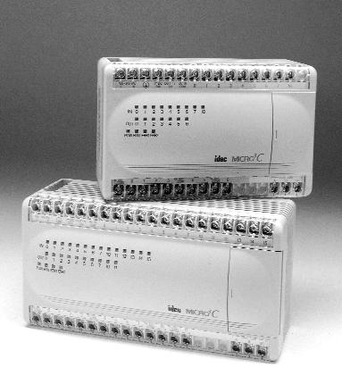
6 1: GENERAL INFORMATION Introduction This chapter describes general information about additional functions and specifications incorporated in the MICRO 3 C. For general information, functions, and specifications inherited from the MICRO 3, see the MICRO 3 User s Manual. Features MICRO 3 C has upgraded functions for communications. The new functions are particularly useful for modem communication, user communication, and monitoring data communication. User Communication Function MICRO 3 C has an RS232C loader port in place of the RS485 loader port on the MICRO 3. The more widely applicable RS232C loader port can be directly connected to any equipment with an RS232C communication port. New advanced instructions for transmitting and receiving data make it possible to set up a communication system using various communication formats. The user communication function can be used only in the standard processing mode, not in the high-speed processing mode. Increased Data Registers Since data communication requires more data registers, MICRO 3 C has 500 data registers (D0 through D499) expanded from 100 data registers in the MICRO 3. All expanded data registers except D499 can be used to program instructions. In the high-speed processing mode, available data registers are limited to 32 (D0 through D31) as with the MICRO 3. Double-word Comparison of Data Registers Double-word comparison instruction is added to compare data in data registers. Two consecutive data registers designated by a source operand are compared with two consecutive data registers designated by another source operand. When used with a repeat designation, one double-word comparison instruction can execute a maximum of 31 double-word comparison operations. With a repeat designation, the results of all double-word comparisons can not only be available individually but also be ANDed; so the comparison results can be easily determined even when comparing a large quantity of data. Parts Description Function Selector Switch Selects the station function in the expansion or data link system. Analog Potentiometer Sets the analog value for the analog timer, frequency, or pulse width of pulse outputs. MICRO 3 C has only one potentiometer while 16- and 24-I/O type MICRO 3 base units have two potentiometers. Protocol Selector Switch Selects the communication protocol for the loader port (loader protocol or user protocol) and the data link terminals (data link/expansion link or loader protocol). Loader Port For connecting the program loader or computer. The loader port can also be used as a user communication port when user protocol is selected with the protocol selector switch. Communication Enable Button Enables the communication mode selected with the protocol selector switch. When the protocol selector switch setting is changed while the MICRO 3 C is powered up, press this button to enable the new communication mode for the loader port and data link terminals. Data Link Terminals For connecting the data link line in the expansion link or data link system. The data link terminals can also be used for connecting the program loader or computer when loader protocol is selected with the protocol selector switch DATA LINK A B SG The figure above illustrates the 16-I/O type MICRO 3 C base unit. USER S MANUAL 1-1
7 1: GENERAL INFORMATION Protocol Selector Switch The protocol selector switch is used to select communication modes for the RS232C loader port and the RS485 data link terminals. When the MICRO 3 C is powered up, the selected communication modes are enabled automatically. If the protocol selector switch setting is changed after the MICRO 3 C is powered up, the new setting does not take effect until the communication enable button is depressed. Communication Protocols for Loader Port and Data Link Terminals Protocol Selector Switch Position Loader Port Protocol Data Link Terminal Protocol Remarks 0 Loader protocol Data link protocol 1 User protocol Data link protocol 2 Loader protocol Loader protocol 3 User protocol Loader protocol 4 Loader protocol Loader protocol For maintenance (Note 1) 5 through 7 Reserved Reserved (Note 2) Loader protocol: The protocol used for communication between MICRO 3 C and program loader or CUBIQ on computer. User protocol: The protocol used for user communication instructions (RS232C) Data link protocol: The protocol used for communication in the expansion link or data link (RS485). Note 1: When the protocol selector switch is set to 4, the communication parameters for the loader port are arbitrarily set to the default values of FUN8 (loader port communication mode setting); baud rate 9,600 bps, terminator code 0D, 7 data bits, even parity, 1 stop bit, and receive timeout 500 msec. Any change in FUN8 values does not take effect. The communication parameters for the data link terminals using the loader protocol are fixed and the same as the FUN8 default values. Note 2: When the protocol selector switch is set to 5 through 7, the ERR1 indicator on the MICRO 3 C blinks and the MICRO 3 C does not start to run. Communication Enable Button While the MICRO 3 C is powered up, pressing the communication enable button for more than 4 seconds until the ERR1 indicator blinks once makes the MICRO 3 C read the settings on the protocol selector switch and function selector switch. Then the MICRO 3 C updates the communication modes for the loader port and data link terminals. This button is useful when you want to change the communication mode without turning power off. Warning If the communication enable button is pressed while the MICRO 3 C is in operation, the user program execution is stopped and all outputs are forced off. Function Selector Switch When the protocol selector switch is set to 0 or 1, the data link terminals can be used for expansion link or data link communication. Then the function selector switch selects the station function for each MICRO 3 C in the expansion link or data link system. The function of the function selector switch on the MICRO 3 C is the same as that on the MICRO 3. When the protocol selector switch is set to 2 through 4 to select loader protocol for the data link terminals, the function selector switch setting has no effect. MICRO 3 C Station Function by Function Selector Switch Position Function Selector Switch Position MICRO 3 C Station Function 0 Base or master station 1 Slave station 1 2 Slave station 2 3 Slave station 3 4 Slave station 4 5 Slave station 5 6 Slave station 6 7 Expansion station 1-2 USER S MANUAL
8 1: GENERAL INFORMATION System Setup This section describes various system configurations using the MICRO 3 C and required settings. Selecting Communication Mode Set the function selector switch and the protocol selector switch to select a desired communication mode for the loader port and data link terminals. After changing the settings of the function selector switch and protocol selector switch while the MICRO 3 C is powered up, press the communication enable button for more than 4 seconds until the ERR1 indicator blinks once; then the new communication mode takes effect. When the MICRO 3 C is powered up, the MICRO 3 C checks the settings of the function selector switch and protocol selector switch and enables the selected communication mode automatically. You have to press the communication enable button only when you change the communication mode while the MICRO 3 C is powered up. Warning If the communication enable button is pressed while the MICRO 3 C is in operation, the user program execution is stopped and all outputs are forced off. Connecting Program Loader to the Loader Port When connecting a program loader to the loader port on the MICRO 3 C, set the protocol selector switch to 0, 2, or 4 to select loader protocol for the loader port. Use the loader cable 3C to connect the program loader to the MICRO 3 C loader port. Caution Special cables are needed to connect to the loader port on the MICRO 3 C. Loader cables for the MICRO 3 such as FC2A-KL1 (2m/6.56 ft. long) and FC2A-KL2 (5m/16.4 ft. long) cannot be used for the MICRO 3 C. Cables used for connecting to the loader port on the MICRO 3 C cannot be used for the MICRO 3. If a wrong cable is used, machine damage may result. Loader Cable 3C FC2A-KL3C (2m/6.56 ft. long) The loader cable 3C has an RS232C/RS485 converter in the middle. When connecting and disconnecting the loader cable, be sure to hold the connector. Since the connector has a latch, the cable cannot be removed holding the cable. Make sure of correct direction of the cable as indicated on the direction labels attached near the connectors on the cable. Connecting the Cable The program loader has a cover on the top to select the loader cable connection port or AC adapter jack. Slide the cover to the right to open the loader cable connection port. Connect the connector of the loader cable to the loader cable connection port on the program loader and the other connector of the cable to the loader port on the MICRO 3 C as indicated on the direction labels. Slide the cover to the right Loader Cable Connection Port USER S MANUAL 1-3
9 1: GENERAL INFORMATION Connecting Program Loader to the Data Link Terminals A program loader can also be connected to the data link terminals on the MICRO 3 C when the protocol selector switch is set to 2, 3, or 4 to select loader protocol for the data link terminals. This capability is particularly useful to monitor the communication data transmitted through the loader port while user communication or modem communication is performed with the protocol selector switch set to 3. Loader Cable 4C FC2A-KL4C (2m/6.56 ft. long) The loader cable 4C has a power supply box in the middle. (RS485) (RS485) AC Adapter (Output: 5V DC) The loader cable 4C is not supplied with an AC adapter, which must be prepared by the user. Note: AC adapters for IDEC s FA series PLCs cannot be used. Connecting the Cable The program loader has a cover on the top to select the loader cable connection port or AC adapter jack. Slide the cover to the right to open the loader cable connection port. Connect the connector of the loader cable to the loader cable connection port on the program loader and the three spade terminals on the other end of the cable to the data link terminals on the MICRO 3 C as indicated on the marker tubes. Slide the cover to the right Loader Cable Connection Port Connecting an AC Adapter Connect an AC adapter to the power supply box in the middle of the loader cable 4C to supply power to the program loader. Applicable output plug of the AC adapter is shown on the right. 9.5 ø5.5 ø2.1 Polarity + Dimensions in mm. Caution When a program loader or computer running CUBIQ is connected to the data link terminals and a communication device is connected to the loader port at the same time to perform communications shown below, multi-stage comparison instruction HSC1 cannot be used. Data link terminals: Used for loader protocol communication Loader port: Used for loader protocol communication at 19,200 bps 1-4 USER S MANUAL
10 1: GENERAL INFORMATION Computer Link through Loader Port To set up a 1:1 computer link system, connect an IBM PC or compatible to the MICRO 3 C using the computer link cable 4C (FC2A-KC4C). Set the protocol selector switch to 0, 2, or 4 to select loader protocol for the loader port. Computer Link Cable 4C FC2A-KC4C 3m (9.84 ft.) long To RS232C Port To Loader Port (RS232C) D-sub 9-pin Female Connector Cable Connector Pinouts Pin Description 1 DCD Data Carrier Detect 2 RXD Receive Data 3 TXD Transmit Data 4 DTR Data Terminal Ready 5 GND Signal Ground 6 DSR Data Set Ready 7 8 CTS Clear to Send 9 Computer Link through Data Link Terminals A 1:1 computer link system can also be set up through the data link terminals on the MICRO 3 C using the computer link cable 6C (FC2A-KC6C). Set the protocol selector switch to 2, 3, or 4 to select loader protocol for the data link terminals. Computer Link Cable 6C FC2A-KC6C 2m (6.56 ft.) long To RS232C Port RS232C/RS485 Converter Connect the three spade terminals on the computer link cable 6C to data link terminals A, B, and SG as indicated on the maker tubes. A B SG A B SG (RS485) AC Adapter Output: 5V DC Connect an AC adapter to the RS232C/RS485 converter in the middle of the computer link cable 6C. The computer link cable 6C is not supplied with an AC adapter, which must be prepared by the user. For applicable output plug of the AC adapter, see page 1-4. Note: AC adapters for IDEC s FA series PLCs cannot be used. D-sub 9-pin Female Connector Cable Connector Pinouts Pin Description 1 2 RXD Receive Data 3 TXD Transmit Data 4 5 GND Signal Ground 6 7 RTS Request to Send 8 CTS Clear to Send 9 USER S MANUAL 1-5
11 1: GENERAL INFORMATION Connecting Modem through Loader Port To connect a modem to the loader port on the MICRO 3 C, use the modem cable 1C (FC2A-KM1C). Set the protocol selector switch to 1 or 3 to select user protocol for the loader port. Modem Cable 1C FC2A-KM1C 3m (9.84 ft.) long To RS232C Port Modem To Loader Port (RS232C) D-sub 25-pin Male Connector Cable Connector Pinouts Pin Description 1 FG Frame Ground 2 TXD Transmit Data 3 RXD Receive Data 4 RTS Request to Send SG Signal Ground 8 DCD Data Carrier Detect 20 DTR Data Terminal Ready Connecting RS232C Equipment through Loader Port To connect equipment with an RS232C communication port to the loader port on the MICRO 3 C, use the user communication cable 1C (FC2A-KP1C). One end of the user communication cable 1C is not provided with a connector, and it can be terminated with a proper connector to plug in to communicate with the RS232C port. When the protocol selector switch is set to 1 or 3, MICRO 3 C can communicate with RS232C equipment through the loader port using the user protocol. When the protocol selector switch is set to 0, 2, or 4, MICRO 3 C can communicate through the loader port using the loader protocol. User Communication Cable 1C FC2A-KP1C 2.4m (7.87 ft.) long To RS232C Port RS232C Equipment To Loader Port (RS232C) Attach a proper connector to the open end referring to the cable connector pinouts shown below. Cable Connector Pinouts Pin Description AWG# Color 1 RTS Request to Send 28 Black Twisted 2 DTR Data Terminal Ready 28 Yellow 3 TXD Transmit Data 28 Blue 4 RXD Receive Data 28 Green 5 DSR Data Set Ready 28 Brown 6 SG Signal Ground 28 Gray 7 SG Signal Ground 26 Red Twisted 8 NC No Connection 26 White Cover Shield Signal Direction 1-6 USER S MANUAL
12 1: GENERAL INFORMATION Link Systems MICRO 3 C has three link functions; expansion link, data link, and computer link. When using a link function, the function selector switch and protocol selector switch have to be set and the FUN settings may be required. For details of these settings, see Expansion Link Function and Data Link Function in the MICRO 3 User s Manual and Computer Link 1:N Communication on page 7-1 in this manual. The expansion link cannot be used in the data link system. Expansion Link System The expansion link system consists of two MICRO 3 C or MICRO 3 base units connected through the data link terminals using the optional expansion cable FC2A-KE1 (250 mm/9.84" long) or a shielded twisted pair cable as shown below. The cable for the expansion link system can be extended up to 200 meters (656 feet). Every MICRO 3 C or MICRO 3 base unit can be used as an expansion station. Base Station Function selector switch: 0 Protocol selector switch: 0 or 1 Expansion Station Function selector switch: 7 Protocol selector switch: 0 or 1 The RUN indicator on the expansion station remains off whether the base station is running or stopped. Data Link System The data link system consists of one master station connected to a maximum of six slave stations to communicate control data for distributed control. Every MICRO 3 C or MICRO 3 base unit can be used as a master or slave station. When a slave station performs communication at 19,200 bps through the loader port, multi-stage comparison instruction HSC1 cannot be used at the slave station. Master Station Function selector switch: 0 Protocol selector switch: 0 or 1 Slave Station 1 Function selector switch: 1 Protocol selector switch: 0 or 1 Slave Station 2 Function selector switch: 2 Protocol selector switch: 0 or 1 Slave Station 6 Function selector switch: 6 Protocol selector switch: 0 or 1 Computer Link System In the computer link system, a personal computer is connected to one or a maximum of 32 MICRO 3 C base units to control the operation of all MICRO 3 C base units. The 1:1 computer link system requires the computer link cable 4C (FC2A-KC4C) or computer link cable 6C (FC2A-KC6C). The 1:N computer link system using MICRO 3 C base units requires RS232C/ RS485 converter FC2A-MD1 and cables; computer link interface unit FC2A-LC1 is not required. 1st Unit Function selector switch: 0 Protocol selector switch: 2, 3, or4 FUN9: 0 2nd Unit Function selector switch: 0 Protocol selector switch: 2, 3, or 4 FUN9: 1 Nth Unit (N 32) Function selector switch: 0 Protocol selector switch: 2, 3, or 4 FUN9: N 1 RS232C/RS485 Converter FC2A-MD1 The figure above illustrates a 1:N computer link system for MICRO 3 C. USER S MANUAL 1-7
13 1: GENERAL INFORMATION Communication Specifications This section describes the MICRO 3 C communication specifications. For general specifications, function specifications, I/O specifications, and program loader specifications, see the MICRO 3 User s Manual. Loader Port Communication Specifications Standards Maximum Cable Length Baud Rate Data Bits Parity Communication Parameters Stop Bits Receive Timeout Connection to Program Loader Connection to RS232C Equipment EIA RS232C 15m (49.2 ft.) 1200, 2400, 4800, 9600, bps 7 or 8 bits Odd, Even, None 1 or 2 bits 10 to 2550 msec (In the user communication, receive timeout is disabled when 2550 msec is selected.) Using optional loader cable 3C (FC2A-KL3C) Using optional user communication cable 1C (FC2A-KP1C) or other cables User Communication Mode Specifications When the protocol selector switch is set to 1 or 3 to select user protocol for the loader port, the MICRO 3 C can communicate through the loader port with external equipment which has an RS232C port, such as a computer, modem, printer, or barcode reader. Using transmit and receive instructions for user communication, user programs can be created to match the communication protocol of the equipment to communicate with. Determine the possibility of communication referring to the user communication mode specifications described below: Standards Control Signal Baud Rate Data Bits Parity Stop Bits Receive Timeout Communication Method Maximum Transmit Data Maximum Receive Data EIA RS232C TXD, RXD, DTR, RTS, DSR 1200, 2400, 4800, 9600, bps 7 or 8 bits Odd, Even, None 1 or 2 bits 10 to 2550 msec (10-msec increments) or none (Receive timeout is disabled when 2550 msec is selected.) Start-stop synchronization system half-duplex 200 bytes 200 bytes 1-8 USER S MANUAL
14 1: GENERAL INFORMATION Data Link Terminal Communication Specifications Standards Recommended Cable Conductor Resistance Shield Resistance Maximum Cable Length Isolation Baud Rate Communication Delay Connection to Program Loader EIA RS485 (termination resistor is not required) ø0.9 mm shielded twisted cable 85 Ω/km maximum 12 Ω/km maximum 200m (656 ft.) Between data link terminals of multiple MICRO 3 C units: Not isolated Expansion or data link communication: bps (fixed) Loader protocol communication: 9600 bps (fixed) Expansion link: Master station normal scan time + approx. 9 to 10 msec Data link: Master station normal scan time + approx to 13 msec + Slave station scan time Using optional loader cable 4C (FC2A-KL4C) Data Link Terminal Communication with Program Loader When the protocol selector switch is set to 2, 3, or 4 to select loader protocol for the data link terminals, the MICRO 3 C can communicate through the data link terminals with the program loader or computer to monitor the MICRO 3 C operation, transfer user programs, and perform other communications. The communication parameters using the loader protocol for the data link terminals are fixed to the same values as the FUN8 (loader port communication mode setting) default shown below and cannot be selected unlike the communication through the loader port. Data Link Terminal Communication Parameters (Loader Protocol) Baud Rate Terminator Code Data Bits Parity Stop Bit Receive Timeout 9600 bps 0D (CR) 7 bits Even 1 bit 500 msec When the protocol selector switch is set to 2 or 4, the MICRO 3 C can perform loader communication through both the loader port and data link terminals at the same time. If data write operation (write N bytes or write 1 bit) is attempted to the same operand through both the loader port and data link terminals at the same time, the command through the data link terminals has priority although communication error does not occur at both ports. Caution Some of the program transfer operation cannot be performed as described below: 1. While a user program is written through either the loader port or data link terminals, a user program cannot be written through the other port. The prior write user program operation is executed normally, but the subsequent write user program operation results in a protect error. 2. While a user program is written through either the loader port or data link terminals, a user program cannot be read through the other port. The prior write user program operation is executed normally, but the subsequent read user program operation results in a protect error. 3. A user program cannot be read through either the loader port or data link terminals if a user program is written through the other port before the read user program operation is completed. The subsequent write user program operation is executed normally, but the prior read user program operation may fail to read the complete user program and result in a CRC error. USER S MANUAL 1-9
15 1: GENERAL INFORMATION Dimensions MICRO 3 C Base Unit Program Loader 85 mm (3.346") 95 mm (3.740") 30 mm (1.181") 16-I/O Type: 135 mm (5.315") 24-I/O Type: 165 mm (6.496") 60 mm (2.362") 185 mm (7.283") 80 mm (3.150") 25 mm (0.984") Mounting Hole Layout Minimum center to center 58 mm (2.283") M4 tapped holes or ø4.5 (0.177" dia.) drilled holes 77 mm (3.031") 16-I/O Type: 116 mm (4.567") 24-I/O Type: 146 mm (5.748") Minimum center to center 29 mm (1.142") 1-10 USER S MANUAL
16 2: ALLOCATION NUMBERS Introduction This chapter describes allocation numbers available only for the MICRO 3 C. For details about allocation numbers shared with the MICRO 3, see the MICRO 3 User s Manual. Expanded functions in the MICRO 3 C include: MICRO 3 C has 500 data registers D0 through D499 while MICRO 3 has 100 data registers D0 through D99. D499 is used to enable or disable expansion control data registers D484 through D498 and cannot be used as an ordinary data register to store data. Special internal relay M307 has different functions when used as a base or expansion station in the expansion link system or when used as a master station or slave station in the data link system. Allocation Numbers Available I/O numbers depend on the type and combination of the MICRO 3 C base units used in the expansion link system. For details of available I/O numbers in the expansion link system, see the next page. Input Output Operand Processing Mode Allocation Number Maximum Points Internal Relay Catch Input Relay Special Internal Relay Timer Counter Shift Register Data Register Standard and I0 - I7 I10 - I15 14 points (Base) High-speed + Standard only I20 - I27 I30 - I35 14 points (Expansion) Standard and Q0 - Q7 Q10 - Q11 10 points (Base) High-speed + Standard only Q20 - Q27 Q30 - Q31 10 points (Expansion) Standard and High-speed Standard only Standard and High-speed Standard and High-speed Standard and High-speed Standard only Standard and High-speed Standard only Standard and High-speed Standard only Standard and High-speed Standard only M0 - M7 M10 - M17 M20 - M27 M30 - M37 M40 - M47 M50 - M57 M60 - M67 M70 - M77 M80 - M87 M90 - M97 M100 - M107 M110 - M117 M120 - M127 M130 - M137 M140 - M147 M150 - M157 M160 - M167 M170 - M177 M180 - M187 M190 - M197 M200 - M207 M210 - M217 M220 - M227 M230 - M237 M240 - M247 M250 - M257 M260 - M267 M270 - M277 M280 - M287 M290 - M297 M300 - M307 T0 - T15 T16 - T31 C0 - C15 C16 - C31 R0 - R31 R32 - R63 D0 - D31 D32 - D499 M310 - M points (40 points) 8 points (8 points) 16 points (16 points) 32 points total (16 points total) 64 points (32 points) 500 points (32 points) Notes: Input and output allocation numbers for the expansion station start with I20 and Q20. For the I/O allocation numbers in the expansion link system, see the next page. The maximum points shown in ( ) are values for the high-speed processing mode. The same number cannot be used for a counter and a timer in a user program. Internal relays M260 through M287 have special functions in the modem mode. See page 4-2. Data register D499 is reserved to enable or disable expansion control data registers D484 through D498 and cannot be used as an ordinary data register to store data. For details, see page 2-4. USER S MANUAL 2-1
17 2: ALLOCATION NUMBERS I/O Allocation Numbers for Expansion Link System Input and output allocation numbers do not continue from the base station to the expansion station. At the expansion station, inputs start at I20 and outputs start at Q20. Inputs and outputs are allocated depending on the MICRO 3 C base units used in the expansion link system as shown below: I/O Points Total IN/OUT 16 9/ / / / /20 MICRO 3 C Base Station I/O Allocation Numbers 16-I/O Type I0 - I7 Q0 - Q6 I10 24-I/O Type I0 - I7 I10 - I15 I0 - I7 I10 I0 - I7 I10 I0 - I7 I10 - I15 I0 - I7 I10 - I15 16-I/O Type 16-I/O Type 24-I/O Type 24-I/O Type Q0 - Q7 Q10 - Q11 Q0 - Q6 Q0 - Q6 Q0 - Q7 Q10 - Q11 Q0 - Q7 Q10 - Q11 MICRO 3 C Expansion Station I/O Allocation Numbers I20 - I27 I30 I20 - I27 I30 - I35 I20 - I27 I30 I20 - I27 I30 - I35 16-I/O Type 24-I/O Type 16-I/O Type 24-I/O Type Q20 - Q26 Q20 - Q27 Q30 - Q31 Q20 - Q26 Q20 - Q27 Q30 - Q USER S MANUAL
18 2: ALLOCATION NUMBERS Special Internal Relays Internal relays M290 through M317 are special internal relays with the following functions: Allocation Number Description CPU Stopped Power OFF M290 Input I0 Operating Cleared M291 Input I1 Operating Cleared M292 Input I2 Operating Cleared M293 Catch Input Status Set Input I3 Operating Cleared M294 (See Note below) Input I4 Operating Cleared M295 Input I5 Operating Cleared M296 Input I6 Operating Cleared M297 Input I7 Operating Cleared M300 Start Control Maintained Maintained M301 Initialize Pulse (See Note below) Cleared Cleared M302 All Outputs OFF Cleared Cleared M303 Carry (Cy) or Borrow (Bw) Cleared Cleared M304 User Program Execution Error Cleared Cleared M305 M306 M307 Link Communication Error (Expansion mode and data link mode) Link Communication Prohibit Flag (Expansion mode and data link mode) Link Communication Initialize Flag (Master Station) (Expansion mode and data link mode) Maintained Maintained Cleared Cleared Maintained Cleared Link Communication Stop Flag (Slave Station) (Data link mode) M310 1-sec Clock Reset Cleared Cleared M311 1-sec Clock Operating Cleared M msec Clock Operating Cleared M msec Clock Operating Cleared M314 Timer/Counter Preset Value Changed Maintained Maintained M315 High-speed Counter Soft Reset Maintained Cleared M316 High-speed Counter (HSC3) Overflow Cleared Cleared M317 In-operation Output Cleared Cleared Note: M290 through M297 and M301 are used only for reading in the user program, but can be directly set or reset using the program loader or optional software CUBIQ on a computer. M307 Link Communication Initialize Flag (Master Station)/Link Communication Stop Flag (Slave Station) Special internal relay M307 has different functions when used as a base or expansion station in the expansion link system or when used as a master station or slave station in the data link system. Base or master station: Link communication initialize flag When M307 at the base or master station is turned on during operation, the link configuration is checked to initialize the expansion or data link system. When an expansion station or slave station is powered up after the base or master station, turn M307 on to initialize the link system. After an expansion link or data link setup is changed, M307 must also be turned on to ensure correct communication. Slave station: Link communication stop flag When a slave station does not receive communication data from the master station for 800 msec or more in the data link system, M307 turns on. When the slave station receives correct communication data, M307 turns off. In the expansion station, M307 has no effect and cannot be monitored using the program loader. USER S MANUAL 2-3
19 2: ALLOCATION NUMBERS Data Register Allocation Numbers Available data registers are limited in the high-speed processing mode or in the data link system configuration. Some data registers are allocated to special functions in the data link system as shown below. For the data link function, see the MICRO 3 User s Manual. D100 through D209, D492, and D493 have special functions in the modem mode. See page 4-2. Data Register Number D0 to D31 D32 to D59 D60 to D84 D85 to D89 D90 to D99 D100 to D483 D484 to D485 D486 to D491 D492 to D495 D496 to D498 D499 Other than Data Link Available Standard Processing Mode Data Link (Master Station) Available For data link Data Link (Slave Station) Available For data link Can be designated as control data registers using FUN10. (Note) Available When expansion control data register service is enabled for each group of these data registers using D499, the selected data registers work as expansion control data registers; others can be used as ordinary data registers. When expansion control data register service is disabled using D499, these data registers can be used as ordinary data registers. Reserved to enable or disable expansion control data register service. High-speed Processing Mode Available Not available Note: When FUN10 is set to enable control data registers, selected data registers D90 through D99 work as control data registers; others can be used as ordinary data registers. For details of the data link function, see the MICRO 3 User s Manual. Expansion Control Data Registers Data registers D484 through D499 are allocated as expansion control data registers. D499 is used to enable or disable expansion control data register service for D484 through D498 divided into group 0 through 3. Data registers in the group disabled for expansion control data registers can be used as ordinary data registers. D499 cannot be used as an ordinary data register and must not be programmed to store data of operation results. Group Expansion Control DR Description D499 Expansion control data register service selection D498 D497 D496 D495 D494 D493 D492 D491 D490 D489 D488 D487 D486 D485 (Lower byte) D485 (Upper byte) D484 (Lower byte) D484 (Upper byte) Day (Calendar) Month (Calendar) Year (Calendar) Modem mode selection Reserved Modem mode status Protocol selection in modem mode Control signal status DSR control signal option DTR control signal option RTS control signal option Reserved RTS control signal ON/OFF timer Protocol selector switch value For maintenance Function selector switch value For maintenance Available only for communication through the loader port using user protocol (protocol selector switch set to 1 or 3) 2-4 USER S MANUAL
20 2: ALLOCATION NUMBERS D499 Expansion Control Data Register Service Selection D499 is used to enable or disable expansion control data register service for D484 through D498 divided into group 0 through 3. D499 cannot be used as an ordinary data register and must not be programmed to store data of operation results. If an unexpected value is set to D499, the modem mode may be enabled or disabled Warning during operation. Store a value in D499 to enable or disable expansion control data service for group 0 through 3 as described below: The D499 value marked with indicates that the data registers in the corresponding group are enabled for expansion control data register service. The enable/disable of expansion control data register service is determined by the lower 4 bits in D499. Although a value over 15 can be entered to D499, upper 12 bits do not take effect. Group 0 Group 0 (D496-D498) 1 (D492-D495) 2 (D486-D491) 3 (D484-D485) D498 Day (Calendar) D497 Month (Calendar) D496 Year (Calendar) When group 0 is enabled as expansion control data registers, the calendar data are stored to D496 through D498. The year is indicated with the lower 2 digits. Group 1 D495 Modem mode selection When group 1 is enabled as expansion control data registers and 1 is set to D495, the modem mode is enabled. When 0 is set to D495, the modem mode is disabled. For the modem mode, see page 4-1. D494 Reserved D499 Value D493 Modem mode status When the modem mode is enabled (see above), D493 stores a modem mode status. D493 Value Description Remarks 30h AT command completed normally AT command (start IR) is completed normally. 31h Issuing AT command 32h AT command execution error See the result code stored in data registers D104 through D119. Check the modem power, modem cable, and the remote modem. 33h Two or more start IRs are on Correct the program so that only one start IR goes on at a time. 34h Modem mode enabled 35h Start IR program error Correct the program so that only the disconnect command is issued while the line is connected. 36h (Reserved) 37h (Reserved) 38h Retrying AT command 39h AT command program error Correct the program to include 0Dh in the AT command. D492 Protocol selection in modem mode When the modem mode is enabled (see above), the protocol at the loader port is switched from the user protocol depending on the value in D492 after the telephone line is connected. D492 = 1: User protocol is continued at the loader port D492 = 0: Loader protocol is enabled at the loader port USER S MANUAL 2-5
21 2: ALLOCATION NUMBERS Group 2 D491 Control signal status When group 2 is enabled as expansion control data registers, D491 stores a value to show that RTS, DSR, and DTR are on or off. The data of D491 is updated at every END processing. D491 Value RTS DSR DTR Description 0 OFF OFF OFF All RTS, DSR, and DTR are off. 1 ON OFF OFF RTS is on. 2 OFF ON OFF DSR is on. 3 ON ON OFF RTS and DSR are on. 4 OFF OFF ON DTR is on. 5 ON OFF ON RTS and DTR are on. 6 OFF ON ON DSR and DTR are on. 7 ON ON ON All RTS, DSR, and DTR are on. D490 DSR control signal option When group 2 is enabled as expansion control data registers, D490 is used to control data flow between the MICRO 3 C and the remote terminal depending on the DSR (Data Set Ready) signal of the remote terminal. The DSR signal is an input to the MICRO 3 C to determine the status of the remote terminal. The remote terminal informs the MICRO 3 C using DSR whether the remote terminal is ready for receiving data or is sending valid data. The DSR control signal option can be used only in the user protocol to communicate through the loader port. D490 = 0 (system default): DSR is not used for data flow control. When DSR control is not needed, set 0 to D490. D490 = 1: When DSR is on, MICRO 3 C can transmit and receive data. DSR signal ON OFF Transmit/receive Impossible Possible Impossible Transmit/receive data Data D490 = 2: When DSR is off, MICRO 3 C can transmit and receive data. DSR signal ON OFF Transmit/receive Impossible Possible Impossible Transmit/receive data Data D490 = 3: When DSR is on, MICRO 3 C can transmit data. This function is usually called Busy Control and is used for controlling transmission to a remote terminal with a slow processing speed, such as a printer. When the remote terminal is busy, data input to the remote terminal is restricted. DSR signal ON OFF Transmit Impossible Possible Impossible Transmit data Data 2-6 USER S MANUAL
22 2: ALLOCATION NUMBERS D490 = 4: When DSR is off, MICRO 3 C can transmit data. This function is contrary to D490 = 3. DSR signal ON OFF Transmit Impossible Possible Impossible Transmit data Data D490 = 5: When DSR is on, MICRO 3 C can receive data. DSR signal ON OFF Receive data Data MICRO 3 C receives data arriving while DSR is on. Data out of this range are not received. D490 = 6: When DSR is off, MICRO 3 C can receive data. This function is contrary to D490 = 5. DSR signal ON OFF Receive data Data MICRO 3 C receives data arriving while DSR is off. Data out of this range are not received. D490 = 7 or more: Same as D490 = 0. DSR is not used for data flow control. D489 DTR control signal option When group 2 is enabled as expansion control data registers, D489 is used to control the DTR (Data Terminal Ready) signal to indicate the MICRO 3 C operating status or transmitting/receiving status. The DTR control signal option can be used only in the user protocol to communicate through the loader port. D489 = 0 (system default): While MICRO 3 C is running, DTR is on whether MICRO 3 is transmitting or receiving data. While MICRO 3 C is stopped, DTR remains off. Use this option to indicate the MICRO 3 C operating status. MICRO 3 C Stopped Running Stopped ON DTR signal OFF D489 = 1: While MICRO 3 C is transmitting data, DTR is turned on. While MICRO 3 C is not transmitting data, DTR remains off. Use this option when a remote terminal operates in the half-duplex mode since DTR goes on or off according to the transmit data from MICRO 3 C. Transmit data Transmit data ON DTR signal OFF USER S MANUAL 2-7
23 2: ALLOCATION NUMBERS D489 = 2: While MICRO 3 C is transmitting data, DTR remains off. While MICRO 3 C is not transmitting data, DTR is turned on. The DTR operation at this option is contrary to the operation at D489 = 1. Transmit data Transmit data ON DTR signal OFF D489 = 3: DTR remains off. D489 = 4: While MICRO 3 C can receive data, DTR is turned on. Use this option when flow control of receive data is required. D489 = 5: DTR is turned on or off according to DSR. When DSR is on, DTR is turned on. When DSR is off, DTR remains off. Use this option for returning control signal and acknowledgment when data flow control with the remote terminal is required. DSR signal ON OFF ON DTR signal OFF D489 = 6 or more: Same as D489 = 0. D488 RTS control signal option When group 2 is enabled as expansion control data registers, D488 is used to control the RTS (Request to Send) signal to indicate the MICRO 3 C transmitting/receiving status or operating status. The RTS control signal option can be used only in the user protocol to communicate through the loader port. D488 = 0 (system default): While MICRO 3 C is transmitting data, RTS remains off. While MICRO 3 C is not transmitting data, RTS is turned on. Use this option when a remote terminal operates in the half-duplex mode since RTS goes on or off according to the transmit data from MICRO 3 C. Transmit data Transmit data ON RTS signal OFF D488 = 1: While MICRO 3 C is transmitting data, RTS is turned on. While MICRO 3 C is not transmitting data, RTS remains off. Use this option when a remote terminal operates in the half-duplex mode since RTS goes on or off according to the transmit data from MICRO 3 C. Transmit data Transmit data ON RTS signal OFF D488 = 2: While MICRO 3 C is running, RTS is on whether MICRO 3 C is transmitting or receiving data. While MICRO 3 C is stopped, RTS remains off. Use this option to indicate the MICRO 3 C operating status. MICRO 3 C Stopped Running Stopped ON RTS signal OFF D488 = 3: RTS remains off. 2-8 USER S MANUAL
24 2: ALLOCATION NUMBERS D488 = 4: While MICRO 3 C can receive data, RTS is turned on. Use this option when flow control of receive data is required. D488 = 5: RTS is turned on or off according to DSR. When DSR is on, RTS is turned on. When DSR is off, RTS remains off. Use this option for returning control signal and acknowledgment when data flow control with the remote terminal is required. DSR signal ON OFF ON RTS signal OFF D488 = 6 or more: Same as D488 = 0. D487 Reserved D486 RTS control signal ON/OFF timer When group 2 is enabled as expansion control data registers and D488 is set to 0 or 1 to synchronize the transmit data with the RTS signal, D486 is used to set the amount of time to turn on and off the RTS signal before and after transmitting data. The RTS control signal ON/OFF timer can be used only in the user protocol to communicate through the loader port. D486 = 0 through 249 (Increments 10 msec): Any value over 249 is regarded as 249. The maximum timer error is 20 msec + 2 scan time. Example: D488 = 0 (RTS control signal option) and D486 = 5 ON RTS signal OFF Transmit data Transmit data 50 msec 50 msec MICRO 3 C transmits data 50 msec after RTS is turned off and RTS is turned on 50 msec after data transmission is completed. Since a sufficient amount of time is allowed for the remote terminal after MICRO 3 C has issued RTS, this option is useful when the remote terminal has a slow communication (receiving) speed. Operating Status and Control Signals Communication Mode MICRO 3 C Stopped MICRO 3 C Running User Protocol Modem Mode Loader Protocol DTR and RTS are on, except DTR is off when D489 = 0 RTS is off when D488 = 2 Control signal statuses depend on D488 through D490 options. Initial settings are: DTR and RTS are on as standard. D488 = 2, D489 = 0, D490 = 0 Control signal options have no effect. Communication is executed with D488 = 0, D489 = 0, D490 = 0. When DSR control is used with D490 set to 1 through 4, transmit condition must be satisfied within 5 seconds after the DSR signal has turned to allow transmission. If transmit condition is not met within 5 seconds, the transmit data is invalidated. Then, RTS and DTR take the same statuses as if the data were transmitted. When group 2 is disabled and user communication is used without control signal options, the communication is performed under the same conditions as expansion control data registers are set D488 = 0, D489 = 0, and D490 = 0. USER S MANUAL 2-9
25 2: ALLOCATION NUMBERS Group 3 D485 Protocol selector switch value When group 3 is enabled as expansion control data registers, the lower byte of D485 stores the value set on the protocol selector switch. The upper byte of D485 is reserved for maintenance. To view the protocol selector switch value, monitor D485 in hexadecimal notation on the program loader. MON E OR D 4 8 MCS/R 5 CC= OUT 16 MON D485 $**03 Protocol selector switch value For maintenance D484 Function selector switch value When group 3 is enabled as expansion control data registers, the lower byte of D484 stores the value set on the function selector switch. The upper byte of D484 is reserved for maintenance. To view the function selector switch value, monitor D484 in hexadecimal notation on the program loader. MON E OR D 4 8 MCS/R 4 OUT 16 MON D484 $**01 Function selector switch value For maintenance 2-10 USER S MANUAL
26 3: COMMUNICATION MONITOR Introduction This chapter describes FUN29 user communication status readout and FUN50 user communication data monitor. The FUN29 and FUN50 communication monitor functions can be used when the protocol selector switch is set to 3 to select user protocol for the loader port and loader protocol for the data link terminals. While the MICRO 3 C is communicating through the loader port using the user protocol, the communication status or communication data can be monitored on a program loader or computer connected to the data link terminals. The communication monitor functions are useful for debugging user communication programs. System Setup Protocol Selector Switch Set to 3 to select user protocol for the loader port and loader protocol for the data link terminals RS232C Equipment (modem, printer, computer) To Loader Port To RS232C Port A B SG SG B A To Data Link Terminals (RS485) Loader Cable 4C FC2A-KL4C 2m (6.56 ft.) long Power Supply Box Computer Link Cable 6C FC2A-KC6C 2m (6.56 ft.) long AC Adapter Output: 5V DC For communication monitor functions using a computer, see the CUBIQ User s Manual. FUN29: User Communication Status Readout User communication error data, execution of transmit/receive instructions, and communication parameters can be read using FUN29 on the program loader. FUN 2 9 FUN 29 COM-ERR 0 BRD JMP/E (TXD ) (RXD ) 9600 EVEN 7 (1) Baud rate 1200 bps 2400 bps 4800 bps 9600 bps bps Parity Even Odd None Data bits 7 or 8 bits Stop bits 1 or 2 bits Error code 0: No error 1: Error occurred in received data (parity, framing, overrun error, etc.) Transmit instruction : Not transmitting data : Transmitting data Receive instruction : Not receiving data : Receiving data To return to the editor mode, press the CLR key. USER S MANUAL 3-1
27 3: COMMUNICATION MONITOR FUN50: User Communication Data Monitor Transmit and receive data of user communication between the MICRO 3 C and RS232C equipment can be monitored using FUN50 on the program loader connected to the data link terminals. Before using the FUN50 user communication data monitor, make sure of the correct system setup shown on the preceding page. If the protocol selector switch setting has been changed to 3 after power up, press the communication enable button on the MICRO 3 C until the ERR1 indicator blinks once; then the new communication setting is enabled. First bring the FUN50 screen up pressing the keys: FUN 5 CC= 0 FUN 50 LINE-MON *STOP :(DATA)--- 0 Monitoring ON/OFF STOP: Monitoring is off RUN: Monitoring is on Communication Data Blocks Indicates the quantity of transmit and receive data blocks communicated during monitoring. To start monitoring, move down the cursor to the asterisk on the second line and set the monitoring ON/OFF to RUN: B FUN 50 LINE-MON RUN :(DATA)--- 2 RUN indicates monitoring is on. Increments as MICRO 3 C transmits and receives data during monitoring. To move the cursor up or down, press the or key. Pressing the key toggles RUN and STOP to start or stop monitoring. When monitoring is started by switching to RUN, monitor data stored in the previous monitoring is cleared from memory. Monitor data can be stored up to 30 screens. When the monitor buffer reaches full capacity, FULL is displayed in place of the communication data blocks, stopping communication data monitor. Before displaying the monitored data, first stop monitoring, then move the cursor down to the colon (:) and start to display the monitored data. B ** marks the start of a communication data block ** A B C D Hex code ASCII character display To view the next or preceding screen of monitor data, press the or key. A maximum of 30 screens can be displayed. A communication data block consists of transmit and/or receive data. When the interval between communication characters exceeds 20 msec, the communication data block ends at this point and ** are displayed on a new line to mark the beginning of the next communication data block. To return to the FUN50 screen, press the CLR key. To return to the editor screen, press the CLR key again. After the FUN50 user communication data monitor is completed, press the communication enable button on the MICRO 3 C for 4 seconds until the ERR1 indicator blinks once; then normal communication using the program loader is enabled. If the communication enable button is pressed while a user transmit or receive instruction is executed, the execution is aborted and all outputs are forced off. 3-2 USER S MANUAL
28 4: MODEM MODE Introduction This chapter describes the modem mode designed for communication between the MICRO 3 C and another MICRO 3 C or any data terminal equipment through telephone lines. Using the modem mode, the MICRO 3 C can initialize a modem, dial a telephone number, send an AT command, enable the answer mode to wait for an incoming call, and disconnect the telephone line. All of these operations can be performed simply by turning on a start internal relay dedicated to each operation. Caution The modem mode provides for a simple modem control function so that the MICRO 3 C can initialize a modem, dial a destination telephone number, or answer an incoming call. The performance of the modem communication using the modem mode depends on the modem functions and telephone line situations. The modem mode does not prevent intrusion or malfunctions of other systems. For practical applications, confirm the communication function using the actual system setup and include safety provisions. System Setup To connect a modem to the loader port on the MICRO 3 C, use the modem cable 1C (FC2A-KM1C). To enable the modem mode, make the three settings described below: 1. Set the protocol selector switch to 1 or 3 to select user protocol for the loader port. (See page 1-2.) 2. Enter 6 (7, 14, or 15) to data register D499 to enable expansion control data register service for D486 through D495. (See page 2-5.) 3. Enter 1 to data register D495 to enable the modem mode. (See page 2-5.) Protocol Selector Switch Set to 1 or 3 to select user protocol for the loader port To RS232C Port Modem To Loader Port (RS232C) Modem Cable 1C FC2A-KM1C 3m (9.84 ft.) long D-sub 25-pin Male Connector Mini DIN Connector Pinouts Description Color Pin Shield Cover RTS Request to Send Black 1 DTR Data Terminal Ready Yellow 2 TXD Transmit Data Blue 3 RXD Receive Data Green 4 DSR Data Set Ready Brown 5 SG Signal Ground Gray 6 SG Signal Ground Red 7 NC No Connection White 8 D-sub 25-pin Connector Pinouts Pin Description 1 FG Frame Ground 2 TXD Transmit Data 3 RXD Receive Data 4 RTS Request to Send SG Signal Ground 8 DCD Data Carrier Detect 20 DTR Data Terminal Ready Caution Do not connect the NC (No Connection) pin to any line; otherwise, the MICRO 3 C may be damaged. Modem cables for Apple Macintosh computers cannot be used for the MICRO 3 C. Applicable Modems Any Hayes compatible modem can be used. Modems with a communications rate of 9600 bps or more between modems are recommended. Use modems of the same make and model at both ends of the communication line. In making this user s manual, the correct operation has been confirmed on four modems: AIWA s PV-AF144V5, AIWA s PV-BF144, AIWA s PV-BF288M2, and OMRON s ME1414BII. When using other modems, set a proper initialization string by referring to page 4-3 and confirm operation. USER S MANUAL 4-1
29 4: MODEM MODE Internal Relays for Modem Mode When the modem mode is enabled, internal relays M260 through M287 are allocated to special functions. M260 through M266 are used to send an AT command or disconnect the telephone line. M270 through M276 and M280 through M286 turn on to indicate the results of the command. M267, M277, and M287 are used to indicate the status of the loader port. All of internal relays M260 through M287 are turned off at the first scan in the modem mode. Start and Result Internal Relays Mode Command Start IR Completion IR Failure IR Data Registers Initialization String M260 M270 M280 D135-D159 Originate Mode ATZ (M261) M271 M281 Dialing (M262) M272 M282 D160-D209 Disconnect Mode Disconnect Line M263 M273 M283 AT General Command Mode AT Command M264 M274 M284 D120-D134 Answer Mode Initialization String M265 M275 M285 D135-D159 ATZ (M266) M276 M286 When one of start internal relays M260 through M266 is turned on, a corresponding command is executed once. To repeat the command, reset the start internal relay and turn the internal relay on again. Completion or failure of a command is determined as described below: Completion: Failure: The command is transmitted repeatedly as many as the retry cycles specified in data register D100. When the command is completed successfully, the completion IR is turned on and the command is not executed for the remaining cycles. The command is transmitted repeatedly but failed in all trials as many as the retry cycles specified in data register D100. Loader Port Status Internal Relays Status IR Status Description M267 Protocol Transition ON: Loader port protocol is in transition between loader protocol and user protocol OFF: Loader port protocol is settled to loader protocol or user protocol (Note) M277 Operational State ON: Command mode OFF: On-line mode M287 Line Connection ON: Telephone line connected OFF: Telephone line disconnected Note: While M267 (protocol transition) is on, the MICRO 3 C cannot send and receive communication. Data Registers for Modem Mode When the modem mode is enabled, data registers D100 through D209, D492, and D493 are allocated to special functions. At the first scan in the modem mode, D100 and D135 through D159 store the default values. DR Stored Data Description D100 D101 Retry Cycles (Default = 3) Modify Initialization String (Change \Q3 in the default) 0: No retry 1-99: Executes a specified number of retries 100 or more executes 99 retries 0: \Q3 (used for AIWA s modems) 1 or more: \Q2 (used for OMRON s modems and others) D102-D103 Reserved D104-D119 AT Command Result Code AT command result codes returned from modem are stored D120-D134 AT Command String AT command string for the AT general command mode is stored D135-D159 Initialization String Initialization string for the originate and answer modes is stored D160-D209 Telephone Number Telephone number for dialing in the originate mode is stored Protocol for the loader port after telephone line is connected is selected D492 On-line Mode Protocol 0: Loader protocol 1: User protocol D493 Modem Mode Status Modem mode status is stored (see page 4-6) 4-2 USER S MANUAL
30 4: MODEM MODE Originate Mode The originate mode is used to send an initialization string to the modem, issue the ATZ command to reset the modem, and dial the telephone number. To execute a command, turn on one of start internal relays M260 through M262. If two or more start internal relays are turned on simultaneously, an error will result and error code 33h is stored in modem mode status data register D493 (see page 4-6). When a start internal relay is turned on, a corresponding sequence of commands is executed once as described below. M260: Send initialization string, send the ATZ command, and dial the telephone number M261: Send the ATZ command and dial the telephone number M262: Dial the telephone number Initialization String When the modem mode is enabled as described on page 4-1 and the MICRO 3 C is started to run, the default initialization string is stored to data registers D135 through D154 at the END processing of the first scan. To send the initialization string from the MICRO 3 C to the modem, turn M260 on; then the ATZ command is issued and the telephone number is dialed successively. Default Initialization String: ATE0Q0V1X4\Q3&D2&C1\J0\V0\A0&M5\N2S0=2&W CR LF When D101 (modify initialization string) is set to 0, the default initialization string shown above is stored to data registers D135 through D154. AT and LF are appended at the beginning and end of the initialization string automatically by the system program and are not stored in data registers. DR AT 135 E0 136 Q0 137 V1 138 X4 139 \Q 140 3& 141 D2 142 &C 143 1\ 144 J0 145 \V 146 0\ A0 &M 149 5\ 150 N2 151 S0 152 = &W 0D00 LF This initialization string is used for AIWA s modems. Depending on your modem and telephone line, the initialization string may have to be modified. To replace \Q3 with \Q2 to be used for OMRON s modems and others, set 1 to data register D101 (modify initialization string). More changes can also be made by entering required values to data registers D135 through D159. Store two characters in one data register; the first character at the upper byte and the second character at the lower byte in the data register. AT and LF need not be stored in data registers. Use the MOV (move) instructions to set ASCII values of the initialization string characters and CR at the end. Program the MOV instructions to replace the default values in D135 through D154 stored in the first scan and execute the MOV in a subsequent scan. For essential commands which must be included in the initialization string, see page 4-7. After the new values are stored, turn M260 on to send the new initialization string to the modem. When the initialization string has been sent successfully, internal relay M270 is turned on. If the initialization string fails, internal relay M280 is turned on. When the subsequent commands of ATZ and dialing are also completed successfully, M271 and M272 will also be turned on. The default initialization string or the modified initialization string stored in D135 through D159 is also used for the initialization in the answer mode. ATZ (Resetting the Modem) The default initialization string specifies to be stored in the non-volatile memory of the modem, using the &W command. The initialization string is restored when the modem is powered up or when the ATZ command is issued. MICRO 3 C sends the ATZ command to the modem, following the initialization string when M260 is turned on. The ATZ command can also be issued separately by turning M261 on, followed by the dial command to be executed automatically. ATZ Command: ATZ CR LF When the ATZ command has been completed successfully, internal relay M271 is turned on. If the ATZ command fails, internal relay M281 is turned on. When the subsequent dialing is also completed successfully, M272 will also be turned on. If the initialization string has been stored in the non-volatile memory of the modem, M260 may be skipped. Start with M261 to send the ATZ command. USER S MANUAL 4-3
31 4: MODEM MODE Dialing the Telephone Number When the modem mode is enabled, data registers D160 through D209 are allocated to the telephone number. Before turning on one of the start internal relays M260 through M262 for the originate mode, store the telephone number in data registers starting with D160. One data register stores two characters: the first character at the upper byte and the second character at the lower byte in the data register. Since 50 data registers are allocated to the telephone number, up to 100 characters can be stored, as many as the modem capacity allows. Use the MOV (move) instructions to set ASCII values of the telephone number and execute the MOV instructions before turning on start internal relays M260 through M262. Example of Dial Command: ATDT123 CR LF ATD and LF are appended at the beginning and end of the dial command automatically by the system program and need not be stored in data registers. To program the telephone number of the example above, store ASCII values of T for touchtone phone or P for pulse or rotary phone, followed by the telephone number and CR to data registers starting with D160. D160 D161 D h 3233h 0D00h 54h = T 31h = 1 32h = 2 33h = 3 0Dh = CR All characters subsequent to CR are ignored. As described above, when start internal relay M260 is turned on, the initialization string is sent, followed by the ATZ command and the dial command. When start internal relay M261 is turned on, the ATZ command is sent, followed by the dial command. The dial command can also be sent separately by turning on start internal relay M262. If retry cycles are set to data register D100, the dial command is repeated at intervals of approximately 1 minute as many as the specified retry cycles until the telephone line is connected. When the dial command has been completed successfully, internal relay M272 is turned on. If the dial command fails, internal relay M282 is turned on. The dial command is determined successful when the DCD signal is turned on and when result code CR LF CONNECT CR LF or CR LF CARRIER OK CR LF returned from the modem is received. Note: When the MICRO 3 C is powered down while the telephone line is connected, the telephone line is disconnected because the DTR signal is turned off. This method should not be used for disconnecting the telephone line. Always use M263 to disconnect the telephone line as described on page 4-5. Loader Port Communication Protocol Before the telephone line is connected in the modem mode after power up, the loader port can only send out an AT command by turning on a start internal relay M260 through M266. The communication protocol for the loader port after the telephone line is connected is selected by the value stored in data register D492. D492 Loader Port Communication Protocol in the On-Line Mode 0 Loader protocol 1 User protocol When the telephone line is disconnected, the loader port restores the state as before the telephone line is connected, whether D492 is set to 0 or 1. When using a TXD or RXD instruction in the user communication mode while the telephone line is connected, insert internal relay M287 (line connection) as an input condition for the TXD or RXD instruction. After the telephone line is connected, make sure of an approximately 5-second interval before executing the TXD or RXD instruction until the telephone line connection stabilizes. Note: When the MICRO 3 C is stopped while the telephone line is connected, the loader port protocol changes to the loader protocol even if D492 is set to 1 (user protocol in the on-line mode); then the telephone line remains connected. When the MICRO 3 C is started again, the MICRO 3 C restores the on-line mode. 4-4 USER S MANUAL
32 4: MODEM MODE Disconnect Mode The disconnect mode includes only one command to disconnect the telephone line. To disconnect the telephone line, turn internal relay M263 on. The telephone line is disconnected by turning the DTR signal off since the initialization string includes the &D2 command. While a modem command is executed, another command cannot be executed. If two or more start internal relays are turned on simultaneously, an error will result and error code 33h is stored in modem mode status data register D493 (see page 4-6). When the disconnect command has been completed successfully, internal relay M273 is turned on. If the disconnect command fails, internal relay M283 is turned on. The disconnect command is determined successful when the DCD signal is turned off. After the telephone line is disconnected, the loader port restores the state as before the telephone line is connected whether D492 is set to 0 or 1 so that the loader port can be controlled by turning on a start internal relay M260 through M266. Note: The disconnect mode does not use the escape sequence +++ and the ATH command. AT General Command Mode When the modem mode is enabled, data registers D120 through D134 are allocated to the AT general command string. Before turning on start internal relay M264 for the AT general command mode, store an AT command string in data registers starting with D120. One data register stores two characters: the first character at the upper byte and the second character at the lower byte in the data register. Use the MOV (move) instructions to set the ASCII values of the AT command string and execute the MOV instructions before turning M264 on. Example of AT Command: ATE0Q0V1 CR LF AT and LF are appended at the beginning and end of the AT general command string automatically by the system program and need not be stored in data registers. To program the AT command string of the example above, store ASCII values of the command characters and CR to data registers starting with D120. D120 D121 D h 5130h 5631h 45h = E 30h = 0 51h = Q 30h = 0 56h = V 31h = 1 D123 0D00h 0Dh = CR All characters subsequent to CR are ignored. When the AT general command has been completed successfully, internal relay M274 is turned on. If the AT general command fails, internal relay M284 is turned on. The AT general command is determined successful when result code CR LF OK CR LF returned from the modem is received. USER S MANUAL 4-5
33 4: MODEM MODE Answer Mode The answer mode is used to send an initialization string to the modem and to issue the ATZ command to reset the modem. To execute a command, turn on one of start internal relays M265 or M266. If two or more start internal relays are turned on simultaneously, an error will result and error code 33h is stored in modem mode status data register D493 (see below). When a start internal relay is turned on, a corresponding sequence of commands is executed once as described below. M265: Send initialization string and send the ATZ command M266: Send the ATZ command Initialization String When the modem mode is enabled as described on page 4-1 and the MICRO 3 C is started to run, the default initialization string is stored to data registers D135 through D154 at the END processing of the first scan. To send the initialization string from the data registers to the modem, turn M265 on; then the ATZ command is issued subsequently. Default Initialization String: ATE0Q0V1X4\Q3&D2&C1\J0\V0\A0&M5\N2S0=2&W CR LF As described in the Originate Mode, the initialization string can be modified to match your modem. For details of modifying the initialization string, see page 4-3. When the initialization string has been sent successfully, internal relay M275 is turned on. If the initialization string fails, internal relay M285 is turned on. When the subsequent ATZ command is also completed successfully, M276 will also be turned on. ATZ (Resetting the Modem) The default initialization string specifies to be stored in the non-volatile memory of the modem, using the &W command. The initialization string is restored when the modem is powered up or the ATZ command is issued. MICRO 3 C sends the ATZ command to the modem following the initialization string when M265 is turned on. The ATZ command can also be issued separately by turning M266 on. ATZ Command: ATZ CR LF When the ATZ command has been completed successfully, internal relay M276 is turned on. If the ATZ command fails, internal relay M286 is turned on. If the initialization string has been stored in the non-volatile memory of the modem, M265 may be skipped. Start with M266 to send the ATZ command. Modem Mode Status Data Register When the modem mode is enabled, data register D493 stores a modem mode status. D493 Value Description Remarks 30h AT command completed normally AT command (start IR) is completed normally. 31h Issuing AT command 32h AT command execution error See the result code stored in data registers D104 through D119. Check the modem power, modem cable, and the remote modem. 33h Two or more start IRs are on Correct the program so that only one start IR goes on at a time. 34h Modem mode enabled 35h Start IR program error Correct the program so that only the disconnect command is issued while the line is connected. 36h (Reserved) 37h (Reserved) 38h Retrying AT command 39h AT command program error Correct the program to include 0Dh in the AT command. 4-6 USER S MANUAL
34 4: MODEM MODE Initialization String Commands The default initialization string includes the commands shown below. The commands are described in three categories of importance. For details of modem commands, see the user s manual for your modem. When modifying the initialization string, include the commands in the first category to make sure of correct modem communication. Commands which must be included in the initialization string Commands in this category are essential to use the modem mode. Some modems have the same function by a different command name. Modify the initialization string to match your modem. E0 Characters T echoed Q0 Result codes displayed &D2 Hang up and disable auto-answer on DTR detection When the DTR signal turns off, the telephone line is disconnected. MICRO 3 C uses this function to disconnect the telephone line. \J0 Set bps rate adjust off The bps rate between the modem and the MICRO 3 C or data terminal equipment is constant and independent of the telephone line bps rate. \Q3 When 0 is set to D101 for AIWA s modems, \Q3 is enabled so that CTS and RTS are used for bidirectional hardware flow control. When 1 is set to D101 for OMRON s modems, \Q2 is substituted to set unidirectional hardware flow control. The XON/XOFF flow control cannot be used for the MICRO 3 C modem mode. V1 Word result code &C1 DCD ON with carrier from remote modem DCD tracks the state of the data carrier from the remote modem. An ON condition of DCD indicates the presence of a carrier. \V0 MNP result codes disabled Result codes returned to those controlled by the ATV1 command are set. Reliable link result codes are not used. &W Write active profile The current configuration profile is saved to a non-volatile memory. Command which requires a proper preset value S0 Ring to answer ON Specifies the ring on which the modem will pick up the telephone line. S0=2 specifies that the modem answers an incoming call when detecting 2 ring calls. S0=0 disables the auto-answer function. Most modems have a default of S0=0. Commands which are optional X4 Enables dial tone and busy detection &M5 Enables error correction \N2 Sets the MNP operating mode to the reliable mode buffered error detection. V.42 can also be used. Error correction function is used to improve the communication reliability. \A0 Set MNP maximum block size to 64 bytes Modems are generally configured so that the incoming data from DTE is compressed to a small amount as much as possible before the modem sends out the data to the telephone line; this is in consideration of higher data transmission efficiency and reduced cost. Consequently, modems require processing time after receiving data but before sending out the data to the telephone line. In most applications of the MICRO 3 C, it is desirable that the modem sends out data immediately after the modem has received the data. In addition, the amount of incoming and outgoing data for each communication is considered to be small; so the effect of data compression is small. Note: After setting the initialization string in the primary test phase of modem application, it is recommended that you use the AT\S (display on-line status) and AT%R (display configuration registers) commands on a computer to confirm the modem configuration and parameters. USER S MANUAL 4-7
35 4: MODEM MODE Preparation before Using Modem Before using a modem, read the user s manual for your modem. Determine commands for the initialization string To check if a particular AT command can be used for your modem, use the following method: 1. Store the ASCII values of the command to data registers starting with D120 and turn on internal relay M264 (start IR for AT general command) to send the AT command to the modem. 2. Send the AT command from the terminal mode of communication software on a computer to the modem. Determine the type of the telephone line Consult your local telephone company whether your telephone line is for touch tone phones or pulse dial phones. Determine the dial command according to the type of the telephone line. ATDT Touch tone phones ATDP Pulse dial phones Test the modem operation After the initialization string has been sent to the modem, use the AT\S and AT%R commands on a computer to check the modem configuration and parameters. Setting Communication Parameters Set the FUN8 loader port communication parameters to match those of the modem and DTE connected on the communication line. Since the total of modem communication parameters is 10 bits, set the FUN8 value to a total of 10 bits. Example (FUN8 Default): Data bits 7 Stop bit 1 Parity Even Start bit 1 Total 10 bits When the loader protocol is used for communication, the communication parameters shown above are recommended. Set the baud rate of the MICRO 3 C to a value between 2400 bps and 9600 bps using FUN8. When the program transfer function is used with the loader protocol, set the communications rate between modems to the same value as the baud rate of the MICRO 3 C or a higher speed. Programming Data Registers and Internal Relays To enable the modem mode and communicate through the telephone line, the following settings are needed. 1. Program to move 6 (7, 14, or 15) to data register D499 to enable expansion control register service for D486 through D Program to move 1 to data register D495 to enable the modem mode. 3. Program the destination telephone number if dialing is required. Enter the ASCII values of the telephone number to data registers starting with D160. Store two characters each in one data register. Enter 0Dh at the end of the telephone number. See page Program to move 0 or 1 to data register D101 depending on your modem. When you use AIWA s modem, enter 0 to use the default initialization string. When you use OMRON s modem, enter 1 to substitute \Q2 for \Q3 in the default initialization string. 5. If the default initialization string does not match your modem, program a proper initialization string and enter the ASCII values to data registers starting with D135. Make sure that internal relay M260 (initialization string start IR) is turned on after the new values have been stored to the data registers. See page If you want to change the default value of 3 retry cycles, program to move a required value to data register D Include internal relays M260 through M287 in the user program to control the modem communication as required. Caution Since the modem mode uses control data registers D488 through D490 to control the RTS, DTR, and DSR signals, do not enter any value to these data registers while the modem mode is enabled. 4-8 USER S MANUAL
36 4: MODEM MODE Operating Procedure 1. After completing the user program including FUN8 settings, transfer the user program to the MICRO 3 C from the program loader or a computer running CUBIQ through the loader port or the data link terminals. To transfer the user program, the loader port or the data link terminals must be set to loader protocol using the protocol selector switch. For example, when transferring the user program from the program loader through the data link terminals, set the protocol selector switch to 2, 3, or After transferring the user program, set the protocol selector switch to 1 or 3 to select user protocol for the loader port. Press the communication enable button for 4 seconds until the ERR1 indicator blinks once, if necessary. 3. Start the MICRO 3 C to run the user program. 4. Turn start internal relay M260 or M265 on to initialize the modem. When originating the modem communication, turn M260 on to send the initialization string, the ATZ command, and the dial command. If the initialization string has been stored in the non-volatile memory of the modem, turn M261 on to start with the ATZ command followed by the dial command. When answering an incoming call, turn M265 on send the initialization string and the ATZ command. If the initialization string has been stored in the non-volatile memory of the modem, turn M266 on to send the ATZ command only. 5. Transmit or receive communication through the modem. 6. Turn start internal relay M263 to disconnect the telephone line. Sample Program for Modem Originate Mode This program demonstrates a user program for the modem originate mode to move values to data registers, initialize the modem, dial the telephone number, and disconnect the telephone line. M301 M317 T0 I0 MOV MOV MOV MOV MOV MOV SOTU SOTU S1 6 D1 D499 ** S1 D1 1 D495 ** S S D1 D160 D1 D161 ** ** S1 D1 0 D492 ** S1 D1 0 D101 ** T0 100 M260 M263 END M301 is the initialize pulse special internal relay. Six MOV instructions are used to store values to data registers for the modem mode. 6 D499 to enable control data register service for D486 through D D495 to enable the modem mode (5432h) D160 to designate touch tone and telephone number. 54h = T, 32h = 2 (Dial command ATDT2 CR LF ) 3328 (0D00h) D161 to enter CR at the end of the telephone number. 0 D492 to enable loader protocol for the loader port after connecting the telephone line. 0 D101 to use \Q3 in the default initialization string. M317 is the in-operation output special internal relay. Timer T0 starts to time down when the MICRO 3 C is started to run. When timer T0 times out 10 seconds, M260 is turned on to send the initialization string, ATZ, and dial command to the modem. When input I0 is turned on, M263 is turned on to disconnect the telephone line. Note: If the MICRO 3 C status transition occurs while a user communication TXD or RXD instruction is executed, the user communication is invalidated. Such status transitions include: Modem mode is enabled (6 is set to D499 and 1 is set to D495) Telephone line is connected Loader port communication protocol is changed to loader protocol (0 is set to D492) USER S MANUAL 4-9
37 4: MODEM MODE Checking Modem Operation Confirm the modem operation referring to the user s manual for your modem. Indicator names may differ depending on the brand and model of modems but have the same functions. 1. Make sure the modem is powered up. The POWER indicator must be on. 2. Check that the modem s DTR indicator is on while the MICRO 3 C is in operation. Problem: The DTR indicator is not on. Solution 1: Check the modem cable connection using a VOM. Solution 2: Check that control signal options (D488 through D490) have not been changed. Check that control signal status data register D491 holds a value 4 through 7, indicating that the DTR is on. Above 1 and 2 are confirmed, but modem operation still has a problem. 3. It is not clear if an AT command is issued successfully. Problem: Modem mode status data register D493 does not hold a value 30h or 34h. Solution: Enable the modem mode; set the protocol selector switch to 1 or 3, enter 6 to data register D499, and enter 1 to data register D495. Problem: Solution: Problem: Solution: Modem mode status data register D493 holds a value 32h (AT command execution error). Use the communication monitor function on the program loader or a computer running CUBIQ. Connect the program loader to the data link terminals, and set the protocol selector switch to 3 as shown on page 3-1. Use FUN50 user communication data monitor. Start the MICRO 3 C to run, and issue an AT command. Check to see if the AT command and result code are displayed on the program loader. The AT command is displayed, but the result code is not displayed on the program loader. Check the modem s TXD and RXD signal lines are connected correctly. Problem: Modem mode status D493 holds a value 33h. Solution: Check if two or more start internal relays are on simultaneously. If so, correct the user program to make sure that only one start internal relay is on at a time. 4. An AT command is issued successfully and a result code is received, but the following problem occurs. Problem: When a dial command is issued, DIALTONE is returned and stored in the AT command result code data registers starting with D104. Solution 1: Check that the modular cable is plugged into the LINE jack on the modem. If the modular cable is plugged into the TEL jack on the modem, plug the cable to the LINE jack. Solution 2: When dialing an outside number in a PBX environment, insert the digit used to obtain an outside line after ATDT or ATDP, followed by the W modifier (wait for dial tone) or the, modifier (delay a dial sequence). Problem: Solution: When a dial command is issued repeatedly, CARRIER is returned and stored in the AT command result code data registers starting with D104. Make sure that the same communication parameters and initialization string are set on both the local and remote modems USER S MANUAL
38 5: USER COMMUNICATION INSTRUCTIONS Introduction This chapter describes the programming of the TXD (transmit) instruction and RXD (receive) instruction for user communication. With the protocol selector switch set to 1 or 3 to select user protocol for the loader port, MICRO 3 C can transmit data using the TXD instruction through the loader port to an RS232C remote terminal, such as a computer, printer, or modem. MICRO 3 C can also receive data through the loader port from a remote terminal with an RS232C port. The received data is converted and stored in data registers as designated by the RXD instruction. B1 TXD (Transmit) TXD S1 ***** D1 **** D2 **** When input is on, data designated by S1 is converted into a specified format and transmitted through the loader port to a remote terminal with an RS232C port. Key Operation B ADV 1 BPS 1 S1 (Data) TXD D1: M 0 D2: D 0 Enter operands S1, D1, and D2. Detailed key operation is described on page 5-6. To exit, press the key. Valid Operands (Standard Processing) Operand Function I Q M T C R D Constant Repeat S1 (Source 1) Transmit data h-FFh 1-99 D1 (Destination 1) Transmit completion output D2 (Destination 2) Transmit status Transmit data designated by operand S1 can be a maximum of 200 bytes. When transmission is complete, an output or internal relay, designated by operand D1, is turned on. Destination 2 occupies two consecutive data registers starting with the operand designated by D2. The transmit status data register, designated by D2, stores the status of transmission and error code. The next data register stores the byte count of transmitted data. The same data registers cannot be used as transmit status data registers for TXD instructions and receive status data registers for RXD instructions. If the same data register numbers are programmed as status data registers for TXD and RXD instructions, syntax error 80 will result. Precautions for Programming TXD Instruction 1. MICRO 3 C has 5 formatting areas for executing TXD instructions, so more than 5 TXD instructions cannot be executed at the same time. An error code is set to the transmit status data register, designated by operand D2, in the excessive TXD instructions that cannot be executed. 2. If the input for a TXD instruction is turned on while another TXD instruction is executed, the subsequent TXD instruction is executed 2 scan time after the preceding TXD instruction is completed. 3. Since TXD instructions are executed in each scan while input is on, a pulse input from a SOTU or SOTD instruction should be used as required. 4. In the high-speed processing mode, user communication instructions TXD and RXD cannot be used. USER S MANUAL 5-1
39 5: USER COMMUNICATION INSTRUCTIONS Transmit Data Transmit data is designated by source operand S1 using constant values or data registers. BCC code can also be calculated automatically and appended to the transmit data. One TXD instruction can transmit 200 bytes of data at the maximum. S1 (Source 1) Transmit Data Operand Conversion Type Transmit Digits (Bytes) Repeat Calculation Constant 00h-FFh (7Fh) No conversion 1 Data Register BCC D0-D498 A: Binary ASCII B: Binary BCD ASCII : No conversion A: Binary ASCII : No conversion X: XOR A: ADD Calculation Start Position 1-15 Designating Constant as S1 When a constant value is designated as source operand S1, one-byte data is transmitted without conversion. The valid transmit data value depends on the data bits selected in FUN8 loader port communication mode setting. When 8 data bits are selected, 00h through FFh is transmitted. When 7 data bits are selected as default, 00h through 7Fh is transmitted. Constant values are entered in hexadecimal notation into the source data. Designating Data Register as S1 When a data register is designated as source operand S1, conversion type and transmit digits must also be designated. The data stored in the designated data register is converted and a designated quantity of digits of the resultant data is transmitted. Conversion types are available in Binary ASCII, Binary BCD ASCII, and no conversion. When repeat is designated, data of data registers as many as the repeat cycles are transmitted, starting with the designated data register. Repeat cycles can be up to 99. Conversion Type The transmit data is converted according to the designated conversion type as described below: Example: D10 stores 000Ch (12) (1) Binary ASCII conversion D10 000Ch Binary ASCII conversion 0 (30h) 0 (30h) 0 (30h) C (43h) When transmitting 4 digits (2) Binary BCD ASCII conversion D10 000Ch Binary BCD conversion BCD ASCII conversion 0 (30h) 0 (30h) 0 (30h) 1 (31h) 2 (32h) When transmitting 5 digits (3) No conversion D10 000Ch No conversion (00h) FF (0Ch) When transmitting 2 digits 5-2 USER S MANUAL
40 5: USER COMMUNICATION INSTRUCTIONS Transmit Digits (Bytes) After conversion, the transmit data is taken out in specified digits. Possible digits depend on the selected conversion type. Example: D10 stores 000Ch (12) and is converted in Binary BCD ASCII (1) Transmit Digits = 2 D10 000Ch Binary BCD ASCII conversion 0 (30h) 0 (30h) 0 (30h) 1 (31h) 2 (32h) 1 (31h) 2 (32h) Intermediate result of conversion Lowest 2 digits (2) Transmit Digits = 1 D10 000Ch Binary BCD ASCII conversion 0 (30h) 0 (30h) 0 (30h) 1 (31h) 2 (32h) 2 (32h) Intermediate result of conversion Lowest 1 digit Repeat Cycles When a data register is designated to repeat, consecutive data registers, as many as the repeat cycles, are used for transmit data in the same conversion type and transmit digits. Example: Data register D10 is converted in Binary BCD ASCII and is designated with transmit digits 2. (1) Repeat Cycles = 2 1 (31h) 2 (32h) 3 (33h) 4 (34h) D10 D11 000Ch 0022h Repeat 1 Repeat 2 Binary BCD conversion BCD ASCII conversion (2) Repeat Cycles = 3 D10 000Ch Repeat D h Repeat D h Repeat 3 Binary BCD conversion (31h) BCD ASCII conversion 2 (32h) 3 (33h) 4 (34h) 5 (35h) 6 (36h) BCC (Block Check Character) Block check characters can be appended to the transmit data. The start position for the BCC calculation can be specified from the first byte through the 15th byte. The BCC, calculated in either XOR or ADD, can be 1 or 2 digits. 1st 2nd 3rd 4th 5th 6th 15th 16th 17th 18th 19th STX A B C D E 0 CR LF BCC BCC BCC calculation start position can be selected from this range. BCC (2 digits) BCC calculation range when starting with the 1st byte of the data. USER S MANUAL 5-3
41 5: USER COMMUNICATION INSTRUCTIONS BCC Calculation Start Position The start position for the BCC calculation can be specified from the first byte through the 15th byte. The BCC is calculated for the range starting from the designated position up to the byte immediately before the BCC of the transmit data. Example: Transmit data consists of 17 bytes plus 2 BCC digits. (1) Calculation Start Position = 1 1st 2nd 3rd 4th 5th 6th 15th 16th 17th 18th 19th STX A B C D E 0 CR LF BCC BCC BCC calculation range BCC (2 digits) (2) Calculation Start Position = 2 1st 2nd 3rd 4th 5th 6th 15th 16th 17th 18th 19th STX A B C D E 0 CR LF BCC BCC BCC calculation range BCC (2 digits) BCC Calculation Formula BCC calculation formula can be selected from XOR (exclusive OR) or ADD (addition) operation. Example: Conversion results of transmit data consist of 41h, 42h, 43h, 44h, and 45h. (1) BCC Calculation Formula = XOR 41h 42h 43h 44h 45h = 41h (2) BCC Calculation Formula = ADD 41h + 42h + 43h + 44h + 45h = 14Fh 4Fh (Only the last 1 or 2 digits are used as BCC.) Conversion Type The BCC calculation result can be converted or not according to the designated conversion type as described below: Example: BCC calculation result is 0041h. (1) Binary ASCII conversion 0041h (2) No conversion 0041h Binary ASCII conversion No conversion 4 (34h) 1 (31h) 2 digits (00h) A (41h) 2 digits BCC Digits (Bytes) The quantity of digits (bytes) of the BCC code can be selected from 1 or 2. Example: (1) BCC Digits = 2 4 (34h) 1 (31h) 4 (34h) 1 (31h) (2) BCC Digits = 1 4 (34h) 1 (31h) 1 (31h) 5-4 USER S MANUAL
42 5: USER COMMUNICATION INSTRUCTIONS Transmit Completion Output Designate an output, Q0 through Q31, or an internal relay, M0 through M287, as an operand for the transmit completion output. When the start input for a TXD instruction is turned on, preparation for transmission is initiated, followed by data transmission. When a sequence of all transmission operation is complete, the designated output or internal relay is turned on. Transmit Status Designate a data register, D0 through D497, as an operand to store the transmit status information including a transmission status code and a user communication error code. When the data register designated for the transmit status is monitored in hexadecimal notation on the program loader, the second lowest digit indicates a transmission status code and the lowest digit indicates a user communication error code. If no error exists, the lowest digit indicates 0. To view the transmit status, monitor the designated data register in hexadecimal notation on the program loader. Example: Data register D0 is designated as an operand for the transmit status. MON E OR D 0 OUT 16 MON D 0 $ 40 User communication error code (see page 11-2) Transmit status code (see below) Transmit Status Code Transmit Status Status Code 1 Preparing transmission 2 Transmitting data 3 Data transmission complete 4 Transmit instruction complete Data transmission may be aborted depending on an error. If data transmission is aborted by an error, remove the cause of the error and turn the start input for the TXD instruction on again. For error codes and causes, see User Communication Error Code on page Transmit Data Byte Count The data register next to the operand designated for transmit status stores the byte count of data transmitted by the TXD instruction. When BCC is included in the transmit data, the byte count of the BCC is also included in the transmit data byte count. Example: Data register D100 is designated as an operand for transmit status. Description From turning on the start input for a TXD instruction, until the transmit data is stored in the internal transmit buffer From enabling data transmission by an END processing, until all data transmission is completed From completing all data transmission, until the END processing is completed for the TXD instruction All transmission operation is completed and the next transmission is made possible D100 D101 Transmit status Transmit data byte count USER S MANUAL 5-5
43 5: USER COMMUNICATION INSTRUCTIONS Key Operation for Programming TXD Instruction on Program Loader The following example demonstrates how to program a TXD instruction using the program loader. Data register contents: D010 D011 04D2h 162Eh = 1234 = 5678 Transmit data example: BCC calculation range STX (02h) 1 (31h) 2 (32h) 3 (33h) 4 (34h) 5 (35h) 6 (36h) 7 (37h) 8 (38h) BCC (H) (3Ah) BCC (L) (36h) ETX (03h) Constant D10 D11 BCC Constant Start to program a TXD instruction. B ADV 1 BPS 1 S1 (Data) TXD D1: M 0 D2: D 0 Source 1 (transmit data) Destination 1 (transmit completion output) Destination 2 (transmit status) Enter hexadecimal constant value 02 for STX as transmit data. OUT 16 2 BRD 1 STX (02) Constant Designate data register D10, binary BCD ASCII conversion, 4 transmit digits, and 2 repeat cycles for the next transmit data. E OR D 1 BPS 0 B 4 2 BRD 1 STX (02) 2 D 10 B When repeat cycle is 1, these keys may be omitted. Repeat cycles Transmit digits Conversion type (selected using the key) A: Binary ASCII conversion B: Binary BCD ASCII conversion : No conversion Data register as transmit data source Data position (Nth byte) 1 STX (02h) BCC BCC ETX (H) (L) (32h) (33h) (34h) (35h) (36h) (37h) (38h) (3Ah) (36h) (03h) 1 (31h) Constant D10 D11 BCC Constant 5-6 USER S MANUAL
44 5: USER COMMUNICATION INSTRUCTIONS Enter a BCC code of 2 digits calculated using the ADD format, binary ASCII conversion; calculation is started at the first byte of the transmit data. B B B 2 BRD 1 BPS 1 STX (02) 2 D 10 B BCC AA When BCC calculation starts at the first byte, these keys may be omitted. Calculation start position Quantity of digits Conversion type (selected using the key) A: Binary ASCII conversion : No conversion Calculation format (selected using the key) X: XOR (exclusive OR) A: ADD (addition) Enter hexadecimal constant value 03 for ETX at the end of transmit data. OUT 16 3 BPP 2 D 10 B BCC AA ETX (03) Constant Designate internal relay M10 as an operand for transmit completion output. C SOT M 1 BPS 0 1 S1:(Data) TXD D1: M 10 D2 D 0 To edit the source 1 data, move the cursor to the colon, and press the key. Designate data register D100 as an operand for transmit status. E OR D 1 BPS S1:(Data) TXD D1: M 10 D2 D100 D100: Transmit status D101: Transmit data byte count Complete the programming of the TXD instruction. 0 LOD I 0 1 (TXD ) 10 END 11 END Pressing the key writes the TXD instruction into the program loader memory. To discard the edited data before pressing the key, press the CLR key. Editing the TXD Instruction To edit an existing TXD instruction, move the cursor to the left of the (TXD), and press the key; then the TXD editor screen appears. To edit the source 1 data, press the key again with the cursor at the left of the (Data), and follow the same procedure described above. USER S MANUAL 5-7
45 5: USER COMMUNICATION INSTRUCTIONS B2 RXD (Receive) RXD S1 ***** D1 **** D2 **** When input is on, data received through the loader port from a remote terminal with an RS232C port is converted and stored in data registers according to the receive format designated by S1. Key Operation B ADV 2 1 S1 (Data) BRD RXD D1: M 0 D2: D 0 Enter operands S1, D1, and D2. Detailed key operation is described on page To exit, press the key. Valid Operands (Standard Processing) Operand Function I Q M T C R D Constant Repeat S1 (Source 1) Receive format h-FFh 1-99 D1 (Destination 1) Receive completion output D2 (Destination 2) Receive status Receive format designated by operand S1 can be a maximum of 200 bytes. When data receive is complete, an output or internal relay, designated by operand D1, is turned on. Destination 2 occupies two consecutive data registers starting with the operand designated by D2. The receive status data register, designated by D2, stores the status of data receive and error code. The next data register stores the byte count of received data. The same data registers cannot be used as transmit status data registers for TXD instructions and receive status data registers for RXD instructions. If the same data register numbers are programmed as status data registers for TXD and RXD instructions, syntax error 80 will result. Precautions for Programming RXD Instruction 1. MICRO 3 C can execute a maximum of 5 RXD instructions that have a start delimiter at the same time. If a start delimiter is not programmed in RXD instructions, MICRO 3 C can execute only one receive instruction at a time. If the start input for an RXD instruction is turned on while another RXD instruction without a start delimiter is executed, a user communication error occurs. 2. Since RXD instructions are executed in each scan while input is on, a pulse input from a SOTU or SOTD instruction should be used as required. 3. In the high-speed processing mode, user communication instructions RXD and TXD cannot be used. 5-8 USER S MANUAL
46 5: USER COMMUNICATION INSTRUCTIONS Receive Format Receive format, designated by source operand S1, specifies data registers to store received data, data digits for storing data, data conversion type, and repeat cycles. A start delimiter and an end delimiter can be included in the receive format to discriminate valid incoming communication. When some characters in the received data are not needed, skip can be used to ignore a specified number of characters. BCC code can also be appended to the receive format to verify the received data. One RXD instruction can receive 200 bytes of data at the maximum. S1 (Source 1) Receive Format Data Register Operand D0-D498 Receive Digits (Bytes) Conversion Type Repeat Calculation A: ASCII Binary B: ASCII BCD Binary : No conversion Calculation Start Position 1-99 Start Delimiter 00h-FFh (7Fh) 1 No conversion End Delimiter 00h-FFh (7Fh) 1 No conversion BCC 1-2 A: Binary ASCII : No conversion X: XOR A: ADD 1-15 Skip 1-99 Skip Bytes Designating Data Register as S1 When a data register is designated as source operand S1, receive digits and conversion type must also be designated. The received data is divided into a block of specified receive digits, converted in a specified conversion type, and stored in the designated data register. Conversion types are available in ASCII Binary, ASCII BCD Binary, and no conversion. When repeat is designated, received data is divided, converted, and stored in data registers as many as the repeat cycles, starting with the designated data register. Repeat cycles can be up to 99. Receive Digits The received data is divided into a block of specified receive digits before conversion as described below: Example: Received data of 6 bytes are divided in different receive digits. (Repeat is also designated.) (1) Receive Digits = 2 1 (31h) 2 (32h) (2) Receive Digits = 3 3 (33h) 4 (34h) 5 (35h) 6 (36h) 2 digits 2 digits 2 digits 1st block 2nd block 3rd block 1 (31h) 2 (32h) 3 (33h) 4 (34h) 5 (35h) 6 (36h) 3 digits 1st block 3 digits 2nd block USER S MANUAL 5-9
47 5: USER COMMUNICATION INSTRUCTIONS Conversion Type The data block of the specified receive digits is then converted according to the designated conversion type as described below: Example: Received data has been divided into a 2-digit block. (1) ASCII Binary conversion 1 (31h) 2 (32h) ASCII Binary conversion 0012h (2) ASCII BCD Binary conversion 1 (31h) 2 (32h) ASCII BCD conversion BCD Binary conversion 000Ch (3) No conversion 1 (31h) 2 (32h) No conversion 3132h Repeat Cycles When a data register is designated to repeat, the received data is divided and converted in the same way as specified, and the converted data is stored in consecutive data registers as many as the repeat cycles. Example: Received data of 6 bytes is divided into 2-digit blocks, converted in ASCII Binary, and stored to data registers starting at D20. (1) Repeat Cycles = 2 1 (31h) 2 (32h) 3 (33h) 4 (34h) 2 digits 1st block 2 digits 2nd block Repeat 1 Repeat 2 ASCII Binary conversion D20 D h 0034h (1) Repeat Cycles = 3 1 (31h) 2 (32h) 3 (33h) 4 (34h) 5 (35h) 6 (36h) 2 digits 1st block 2 digits 2nd block 2 digits 3rd block Repeat 1 Repeat 2 Repeat 3 ASCII Binary conversion D20 D21 D h 0034h 0056h 5-10 USER S MANUAL
48 5: USER COMMUNICATION INSTRUCTIONS Designating Constant as Start Delimiter A start delimiter can be programmed at the first byte in the receive format of an RXD instruction; the MICRO 3 C will recognize the beginning of valid communication, although an RXD instruction without a start delimiter can also be executed. When a constant value is designated at the first byte of source operand S1, the one-byte data serves as a start delimiter to start the processing of the received data. The valid start delimiter value depends on the data bits selected in FUN8 loader port communication mode setting. When 8 data bits are selected, start delimiters can be 00h through FFh. When 7 data bits are selected as default, start delimiters can be 00h through 7Fh. Constant values are entered in hexadecimal notation into the source data. A maximum of 5 RXD instructions with different start delimiters can be executed at the same time. When the first byte of the incoming data matches the start delimiter of an RXD instruction, the received data is processed and stored according to the receive format specified in the RXD instruction. If the first byte of the incoming data does not match the start delimiter of any RXD instruction that is executed, MICRO 3 C discards the incoming data and waits for the next communication. While an RXD instruction without a start delimiter is executed, any incoming data is processed continuously according to the receive format. Only one RXD instruction without a start delimiter can be executed at a time. If start inputs to two or more RXD instructions without a start delimiter are turned on simultaneously, one at the smallest address is executed and the corresponding completion output is turned on. Example: (1) When an RXD instruction without a start delimiter is executed 0 (30h) 1st character Incoming Data 1 (31h) 2 (32h) 3 (33h) When D100 is designated as the first data register D100 ****h D101 ****h D100+n ****h The incoming data is divided, converted, and stored to data registers according to the receive format. (2) When RXD instructions with start delimiters STX (02h) and ENQ (05h) are executed STX (02h) Incoming Data 1 (31h) 2 (32h) 3 (33h) Compare ENQ (05h) A (41h) B (42h) C (43h) RXD Instruction 1 STX (02h) When D100 is designated as the first data register RXD Instruction 2 ENQ (05h) When D200 is designated as the first data register D100 D101 D100+n D200 D201 D200+n ****h ****h ****h ****h ****h ****h The incoming data is divided, converted, and stored to data registers according to the receive format. Start delimiters are not stored to data registers. USER S MANUAL 5-11
49 5: USER COMMUNICATION INSTRUCTIONS Designating Constant as End Delimiter An end delimiter can be programmed at other than the first byte in the receive format of an RXD instruction; the MICRO 3 C will recognize the end of valid communication, although RXD instructions without an end delimiter can also be executed. When a constant value is designated at other than the first byte of source operand S1, the one-byte data serves as an end delimiter to end the processing of the received data. The valid end delimiter value depends on the data bits selected in FUN8 loader port communication mode setting. When 8 data bits are selected, end delimiters can be 00h through FFh. When 7 data bits are selected as default, end delimiters can be 00h through 7Fh. Constant values are entered in hexadecimal notation into the source data. If a character in incoming data matches the end delimiter, the RXD instruction ends receiving data at this point and starts subsequent receive processing as specified. Even if a character matches the end delimiter at a position earlier than expected, the RXD instruction ends receiving data there. If a BCC code is included in the receive format of an RXD instruction, an end delimiter can be positioned immediately before or after the BCC code. If a data register or skip is designated between the BCC and end delimiter, correct receiving is not ensured. When an RXD instruction without an end delimiter is executed, data receiving ends when the specified bytes of data in the receive format, such as data registers and skips, have been received. In addition, data receiving also ends when the interval between incoming data characters exceeds the receive timeout value specified in FUN8 loader port communication mode setting whether the RXD has an end delimiter or not. The character interval timer is started when the first character of incoming communication is received and restarted each time the next character is received. When a character is not received after a predetermined time, timeout occurs and the RXD ends data receive operation. Example: (1) When an RXD instruction without an end delimiter is executed 0 (30h) Incoming Data 1 (31h) 2 (32h) 3 (33h) When D100 is designated as the first data register D100 D101 ****h ****h Total of received characters D100+n ****h The incoming data is divided, converted, and stored to data registers according to the receive format. Receive operation is completed when the total characters programmed in RXD are received. (2) When an RXD instruction with end delimiter ETX (03h) and without BCC is executed 1 (31h) Incoming Data 2 (32h) 3 (33h) ETX (03h) When D100 is designated as the first data register D100 D101 ****h ****h End Delimiter End of Receiving Data D100+n ****h The incoming data is divided, converted, and stored to data registers according to the receive format. The end delimiter is not stored to a data register. Any data arriving after the end delimiter is discarded. (3) When an RXD instruction with end delimiter ETX (03h) and one-byte BCC is executed 1 (31h) Incoming Data 2 (32h) ETX (03h) BCC Code When D100 is designated as the first data register D100 D101 ****h ****h End Delimiter End of Receiving Data D100+n ****h The incoming data is divided, converted, and stored to data registers according to the receive format. The end delimiter and BCC code are not stored into data registers. After receiving the end delimiter, MICRO 3 C receives only the one-byte BCC code USER S MANUAL
50 5: USER COMMUNICATION INSTRUCTIONS Skip When skip is designated in the receive format, a specified quantity of digits in the incoming data are skipped and not stored to data registers. A maximum of 99 digits (bytes) of characters can be skipped continuously. Example: When an RXD instruction with skip for 2 digits starting at the third byte is executed 1 (31h) Incoming Data 2 (32h) 3 (33h) 4 (34h) Skipped 5 (35h) 6 (36h) 7 (37h) 8 (38h) When D100 is designated as the first data register D102 D103 D104 D105 D100 D101 ****h ****h ****h ****h ****h ****h BCC (Block Check Character) MICRO 3 C has an automatic BCC calculation function to detect a communication error in incoming data. If a BCC code is designated in the receive format of an RXD instruction, MICRO 3 C calculates a BCC value for a specified starting position through the position immediately preceding BCC and compares the calculation result with the BCC code in the received incoming data. The start position for the BCC calculation can be specified from the first byte through the 15th byte. The BCC, calculated in either XOR or ADD, can be 1 or 2 digits. When an end delimiter is not used in the RXD instruction, the BCC code must be positioned at the end of the receive format designated in Source 1 operand. When an end delimiter is used, the BCC code must be immediately before or after the end delimiter. MICRO 3 C reads a specified number of BCC digits in the incoming data according to the receive format to calculate and compare the received BCC code with the BCC calculation results. BCC Calculation Start Position The start position for the BCC calculation can be specified from the first byte through the 15th byte. The BCC is calculated for the range starting from the designated position up to the byte immediately before the BCC of the receive data. Example: Received data consists of 17 bytes plus 2 BCC digits. (1) Calculation Start Position = 1 1st 2nd 3rd 4th 5th 6th 15th 16th 17th 18th 19th STX A B C D E 0 CR LF BCC BCC BCC calculation range BCC (2 digits) (2) Calculation Start Position = 2 1st 2nd 3rd 4th 5th 6th 15th 16th 17th 18th 19th STX A B C D E 0 CR LF BCC BCC BCC calculation range BCC (2 digits) USER S MANUAL 5-13
51 5: USER COMMUNICATION INSTRUCTIONS BCC Calculation Formula BCC calculation formula can be selected from XOR (exclusive OR) or ADD (addition) operation. Example: Incoming data consist of 41h, 42h, 43h, 44h, and 45h. (1) BCC Calculation Formula = XOR 41h 42h 43h 44h 45h = 41h (2) BCC Calculation Formula = ADD 41h + 42h + 43h + 44h + 45h = 14Fh 4Fh (Only the last 1 or 2 digits are used as BCC.) Conversion Type The BCC calculation result can be converted or not according to the designated conversion type as described below: Example: BCC calculation result is 0041h. (1) Binary ASCII conversion 0041h (2) No conversion 0041h Binary ASCII conversion No conversion 4 (34h) 1 (31h) 2 digits (00h) A (41h) 2 digits BCC Digits (Bytes) The quantity of digits (bytes) of the BCC code can be selected from 1 or 2. Example: (1) BCC Digits = 2 4 (34h) 1 (31h) 4 (34h) 1 (31h) (2) BCC Digits = 1 4 (34h) 1 (31h) 1 (31h) 5-14 USER S MANUAL
52 5: USER COMMUNICATION INSTRUCTIONS Comparing BCC Codes MICRO 3 C compares the BCC calculation result with the BCC code in the received incoming data to check for any error in the incoming communication due to external noises or other causes. If a disparity is found in the comparison, an error code is stored in the data register designated as receive status in the RXD instruction. For user communication error code, see page Example 1: BCC is calculated for the first byte through the sixth byte using the XOR format, converted in binary ASCII, and compared with the BCC code appended to the seventh and eighth bytes of the incoming data. Incoming Data 1 (31h) 2 (32h) 3 (33h) 4 (34h) 5 (35h) 6 (36h) 0 (30h) 7 (37h) BCC Calculation Range BCC BCC Calculation Result 31h 32h 33h 34h 35h 36h = 07h Binary ASCII Conversion Comparison result is true to indicate that data is received correctly. 0 (30h) 7 (37h) Example 2: BCC is calculated for the first byte through the sixth byte using the ADD format, converted in binary ASCII, and compared with the BCC code appended to the seventh and eighth bytes of the incoming data. Incoming Data 1 (31h) 2 (32h) 3 (33h) 4 (34h) 5 (35h) 6 (36h) 0 (30h) 7 (37h) BCC Calculation Range BCC BCC Calculation Result 31h + 32h + 33h + 34h + 35h + 36h = 135h Binary ASCII Conversion Comparison result is false. Error code 9 is stored in the receive status data register. 3 (33h) 5 (35h) Receive Completion Output Designate an output, Q0 through Q31, or internal relay, M0 through M287, as an operand for the receive completion output. When the start input for an RXD instruction is turned on, preparation for receiving data is initiated, followed by data conversion and storage. When a sequence of all data receive operation is complete, the designated output or internal relay is turned on. USER S MANUAL 5-15
53 5: USER COMMUNICATION INSTRUCTIONS Receive Status Designate a data register, D0 through D497, as an operand to store the receive status information including a receive status code and a user communication error code. When the data register designated for the receive status is monitored in hexadecimal notation on the program loader, the second lowest digit indicates a receive status code and the lowest digit indicates a user communication error code. If no error exists, the lowest digit indicates 0. To view the receive status, monitor the designated data register in hexadecimal notation on the program loader. Example: Data register D0 is designated as an operand for the receive status. MON E OR D 0 OUT 16 MON D 0 $ 40 User communication error code (see page 11-2) Receive status code (see below) Receive Status Code Receive Status Code Status 1 Preparing data receive 2 Receiving data 3 Data receive complete 4 Receive instruction complete Data receive may be aborted depending on an error. If data receive is aborted by an error, remove the cause of the error and turn the start input for the RXD instruction on again. For error codes and causes, see User Communication Error Code on page Receive Data Byte Count The data register next to the operand designated for receive status stores the byte count of data received by the RXD instruction. When a start delimiter, end delimiter, and BCC are included in the received data, the byte counts for these codes are also included in the receive data byte count. Example: Data register D200 is designated as an operand for receive status. Description From turning on the start input for an RXD instruction to read the receive format, until the RXD instruction is enabled by an END processing From enabling the RXD instruction by an END processing, until incoming data is received From receiving incoming data, until the received data is converted and stored in data registers according to the receive format All data receive operation is completed and the next data receive is made possible D200 D201 Receive status Receive data byte count 5-16 USER S MANUAL
54 5: USER COMMUNICATION INSTRUCTIONS Key Operation for Programming RXD Instruction on Program Loader The following example demonstrates how to program an RXD instruction including a start delimiter, skip, BCC, and end delimiter using the program loader. Converted data is stored to data registers D20 and D21. Internal relay M20 is used as destination D1 for the receive completion output. Data register D200 is used as destination D2 for the receive status, and data register D201 is used to store the receive data byte count. Receive data example: BCC calculation range STX (02h) 1 (31h) 2 (32h) 3 (33h) 4 (34h) 5 (35h) 6 (36h) 7 (37h) 8 (38h) 9 (39h) 0 (30h) A (41h) B (42h) BCC (H) (39h) BCC (L) (32h) ETX (03h) Start Skip Stored to D20 Stored to D21 BCC End Delimiter Delimiter Start to program an RXD instruction. B ADV 2 1 S1 (Data) BRD RXD D1: M 0 D2: D 0 Source 1 (receive format) Destination 1 (receive completion output) Destination 2 (receive status) Enter hexadecimal constant value 02 for STX as a start delimiter in the receive format. OUT 16 2 BRD 1 STX (02) A constant entered at the first byte specifies the start delimiter. Designate 4 bytes to skip. B B 4 1 STX (02) 2 SKIP Skip byte count Designate data register D20, ASCII binary conversion, 4 digits, and 2 repeat cycles. E OR D 2 BRD B BRD 1 STX (02) 2 SKIP 4 6 D 20 A Data position (Nth byte) When repeat cycle is 1, these keys may be omitted. Repeat cycles Receive digits Conversion type (selected using the key) A: ASCII Binary conversion B: ASCII BCD Binary conversion : No conversion Data register to store received data 1 STX (02h) A B BCC BCC ETX (H) (L) (32h) (33h) (34h) (35h) (36h) (37h) (38h) (39h) (30h) (41h) (42h) (39h) (32h) (03h) 1 (31h) USER S MANUAL 5-17
55 5: USER COMMUNICATION INSTRUCTIONS Enter a BCC code of 2 digits calculated using the ADD format, binary ASCII conversion; calculation is started at the first byte of the received data. B B B 2 BRD 1 BPS 2 SKIP 4 6 D 20 A BCC AA When BCC calculation starts at the first byte, these keys may be omitted. Calculation start position Quantity of digits Conversion type (selected using the key) A: Binary ASCII conversion : No conversion Calculation format (selected using the key) X: XOR (exclusive OR) A: ADD (addition) Enter hexadecimal constant value 03 for ETX as an end delimiter in the receive format. OUT 16 3 BPP 6 D 20 A BCC AA ETX (03) A constant entered at other than the first byte specifies the end delimiter. Designate internal relay M20 as an operand for receive completion output. C SOT M 2 BRD 0 1 S1:(Data) RXD D1: M 20 D2 D 0 To edit the source 1 data, move the cursor to the colon, and press the key. Designate data register D200 as an operand for receive status. E OR D 2 BRD S1:(Data) TXD D1: M 20 D2 D200 D200: Receive status D201: Receive data byte count Complete the programming of the RXD instruction. 0 LOD I 1 1 (RXD ) 11 END 12 END Pressing the key writes the RXD instruction into the program loader memory. To discard the edited data before pressing the key, press the CLR key. Editing the RXD Instruction To edit an existing RXD instruction, move the cursor to the left of the (RXD), and press the key; then the RXD editor screen appears. To edit the source 1 data, press the key again with the cursor at the left of the (Data), and follow the same procedure described above USER S MANUAL
56 6: COMPARISON INSTRUCTION Introduction This chapter describes the programming of the CMP2 (double-word comparison) instruction. This instruction is useful to compare data received using the user communication. The CMP2 instruction compares data in data registers. Two consecutive data registers designated by a source operand are compared with two consecutive data registers designated by another source operand. When used with a repeat designation, one CMP2 instruction can execute a maximum of 31 double-word comparison operations. With a repeat designation, the results of all double-word comparisons can be ANDed; so, the comparison results are easily determined, even when comparing a large amount of data. B3 CMP2 (Double-word Comparison) TXD S1(R) **** S2(R) **** D1(R) **** ** (S1)(S1+1) = (S2)(S2+1) D1 on When input is on, 32-bit data designated by source operands S1 and S1+1 is compared with 32-bit data designated by source operands S2 and S2+1. When (S1)(S1+1) data is equal to (S2)(S2+1) data, destination operand D1 is turned on. When the condition is not met, D1 is turned off. Key Operation B ADV 3 1 S1 BPP CMP2 S2: D1: Enter operands S1, S2, and D1. When repeat is required, press the key for the operand to repeat, and enter the number of repeat cycles. To exit, press the key. Valid Operands (Standard Processing) Operand Function I Q M T C R D Constant Repeat S1 (Source 1) Data to compare S2 (Source 2) Data to compare D1 (Destination 1) Comparison output In the high-speed processing mode, operands for advanced instructions are limited. See page 2-1. Examples: CMP2 The comparison output is usually maintained while the input to the comparison instruction is off. If the comparison output is on, the on status is maintained when the input is turned off as demonstrated by this program. I0 CMP2 S1 D10 S2 D20 D1 Q0 ** This program turns the output off when the input is off. Input I0 ON OFF Comparison D10 D11 = D20 D21 Result D10 D11 D20 D21 Comparison Output Q0 ON OFF I0 CMP2 M0 S1 D10 S2 D20 D1 M0 ** Q0 Input I0 ON OFF Comparison D10 D11 = D20 D21 Result D10 D11 D20 D21 Output Q0 ON OFF USER S MANUAL 6-1
57 6: COMPARISON INSTRUCTION Repeat Operation in the Double-word Comparison Instruction Unlike other advanced instructions, when S1 and/or S2 (source) is designated to repeat and D1 (destination) is not designated to repeat, the comparison results are ANDed and set to one destination. When only S1 (source) is designated to repeat, double-word operands (as many as the repeat cycles, starting with the operand designated by S1) are compared with the double-word operand designated by S2. The comparison results are ANDed and set to the operand designated by D1. I1 CMP2 S1 R D20 S2 D30 D1 M50 3 S1 (Repeat = 3) S2 (Repeat = 0) D1 (Repeat = 0) D20 D21 D22 D23 D24 D25 D30 D31 D30 D31 D30 D31 When only S2 (source) is designated to repeat, the double-word operand designated by S1 is compared with double-word operands (as many as the repeat cycles, starting with the operand designated by S2). The comparison results are ANDed and set to the operand designated by D1. AND M50 I2 CMP2 S1 D20 S2 R D30 D1 M50 3 S1 (Repeat = 0) S2 (Repeat = 3) D1 (Repeat = 0) D20 D21 D20 D21 D20 D21 D30 D31 D32 D33 D34 D35 AND M50 When S1 (source) and S2 (source) are designated to repeat, double-word operands (as many as the repeat cycles, starting with the operands designated by S1 and S2) are compared with each other. The comparison results are ANDed and set to the operand designated by D1. I3 CMP2 S1 R D20 S2 R D30 D1 M50 3 S1 (Repeat = 3) S2 (Repeat = 3) D1 (Repeat = 0) D20 D21 D22 D23 D24 D25 D30 D31 D32 D33 D34 D35 AND M50 When S1 (source) and D1 (destination) are designated to repeat, double-word operands (as many as the repeat cycles, starting with the operand designated by S1) are compared with the double-word operand designated by S2. The comparison results are set to operands (as many as the repeat cycles, starting with the operand designated by D1). I4 CMP2 S1 R D20 S2 D30 D1 R M50 3 S1 (Repeat = 3) S2 (Repeat = 0) D1 (Repeat = 3) D20 D21 D22 D23 D24 D25 D30 D31 D30 D31 D30 D31 M50 M51 M52 When S2 (source) and D1 (destination) are designated to repeat, the double-word operand designated by S1 is compared with double-word operands (as many as the repeat cycles, starting with the operand designated by S2). The comparison results are set to operands (as many as the repeat cycles, starting with the operand designated by D1). I5 CMP2 S1 D20 S2 R D30 D1 R M50 3 S1 (Repeat = 0) S2 (Repeat = 3) D1 (Repeat = 3) D20 D21 D20 D21 D20 D21 D30 D31 D32 D33 D34 D35 M50 M51 M52 When S1, S2 (source), and D1 (destination) are designated to repeat, double-word operands (as many as the repeat cycles, starting with the operands designated by S1 and S2) are compared with each other. The comparison results are set to operands (as many as the repeat cycles, starting with the operand designated by D1). I6 CMP2 S1 R D20 S2 R D30 D1 R M50 3 S1 (Repeat = 3) S2 (Repeat = 3) D1 (Repeat = 3) D20 D21 D22 D23 D24 D25 D30 D31 D32 D33 D34 D35 M51 M50 M USER S MANUAL
58 7: COMPUTER LINK Introduction This chapter describes the computer link 1:N communication system for controlling multiple MICRO 3 C units from a computer. Unlike the computer link 1:N communication system for the MICRO 3, shielded twisted pair cables from the RS232C/ RS485 converter can be connected to data link terminals on the MICRO 3 C directly, without the need for the computer link interface units and computer link interface cables. A computer can also communicate with a MICRO 3 C network through modems. For the MICRO 3 C computer link 1:1 communication, see page 1-5. Computer Link 1:N Communication To set up a 1:N computer link system, connect a computer to RS232C/RS485 converter using RS232C cable HD9Z-C52. Connect the RS232C/RS485 converter to MICRO 3 C units using shielded twisted pair cables. Supply power to the RS232C/RS485 converter by connecting a 24V DC source to terminals 6 and 7 or by plugging an AC adapter to the DC IN jack. For specifications of the AC adapter, see page 7-4. POWER RS232C/RS485 Converter FC2A-MD1 132H 110W 34D mm (5.917"H 4.331"W 1.339"D) RS485 SERIAL PORT 1 T 2 A 3 B 4 SG 5 FG RS232C/RS485 CONVERTER Type FC2A-MD1 POWER SUPPLY 24V DC DC IN + 24V DC or AC Adapter (9V DC, 350 ma) SD RD RS232C SERIAL PORT To RS232C Port D-sub 25-pin Male Connector RS232C Cable HD9Z-C52 1.5m (4.92 ft.) long To RS232C Port D-sub 9-pin Female Connector 1st Unit Function selector switch: 0 Protocol selector switch: 2, 3, or 4 FUN9: 0 2nd Unit Function selector switch: 0 Protocol selector switch: 2, 3, or 4 FUN9: 1 A B SG A B SG Shielded twisted pair cable 200m (656 ft.) maximum Nth Unit (N 32) Function selector switch: 0 Protocol selector switch: 2, 3, or 4 FUN9: N 1 3rd Unit Function selector switch: 0 Protocol selector switch: 2, 3, or 4 FUN9: 2 A B SG A B SG Select a unique device number, from 0 through 31, for each MICRO 3 C using FUN9 PLC address for network communication on the program loader, and transfer the user program to the MICRO 3 C. USER S MANUAL 7-1
59 7: COMPUTER LINK Computer Link 1:N Communication Using Modems A 1:N computer link system can also be controlled through modems using RS232C/RS485 converter FC2A-MD1. Connect a computer and the RS232C/RS485 converter to modems using RS232C straight cables. Connect the RS232C/RS485 converter to MICRO 3 C units using shielded twisted pair cables. Supply power to the RS232C/RS485 converter by connecting a 24V DC source to terminals 6 and 7 or by plugging an AC adapter to the DC IN jack. For specifications of the AC adapter, see page 7-4. POWER RS232C/RS485 Converter FC2A-MD1 132H 110W 34D mm (5.917"H 4.331"W 1.339"D) RS485 SERIAL PORT 1 T 2 A 3 B 4 SG 5 FG RS232C/RS485 CONVERTER Type FC2A-MD1 POWER SUPPLY 24V DC DC IN + 24V DC or AC Adapter (9V DC, 350 ma) SD RD RS232C SERIAL PORT RS232C Straight Cable Modem Telephone Line Modem RS232C Straight Cable Note: When connecting a computer to RS232C/RS485 converter FC2A-MD1 directly, use RS232C cable HD9Z-C52. 1st Unit Function selector switch: 0 Protocol selector switch: 2, 3, or 4 FUN9: 0 2nd Unit Function selector switch: 0 Protocol selector switch: 2, 3, or 4 FUN9: 1 MICRO 3 C MICRO 3 C A B SG A B SG Shielded twisted pair cable 200m (656 ft.) maximum MICRO 3 can also be connected to the computer link 1:N communication using RS232C/RS485 converter FC2A-MD1 for modems. For connecting the MICRO 3 to the network, use the computer link interface unit and computer link interface cable. Nth Unit (N 32) Function selector switch: 0 FUN9: N 1 MICRO 3 A B SG FG Computer Link Interface Unit FC2A-LC1 69.5H 55W 35.5D mm (2.736"H 2.165"W 1.398"D) Computer Link Interface Cable FC2A-KC3 100 mm (3.937") long In the 1:N communication network, MICRO 3 C cannot send the initialization string to the modem. The modem must be initialized in advance using the following initialization string. This string is different from the default initialization string in the MICRO 3 C modem mode. Initialization String: ATE0V0X0\J1\N0\Q0&D0S0=2&W E0 Character T echoed V0 Digit result code X0 Disables dial tone and busy detection \J1 Set bps rate adjust on \N0 Normal mode buffered no error detection \Q0 Disables flow control &D0 Ignore DTR signal S0=2 Answer on the second ring &W Write active profile into non-volatile memory 7-2 USER S MANUAL
60 7: COMPUTER LINK RS232C/RS485 Converter FC2A-MD1 The RS232C/RS485 converter FC2A-MD1 is used with the MICRO 3 C and the MICRO 3 to convert data signals between EIA RS232C and EIA RS485. This converter makes it possible to connect a host device with RS232C interface to multiple MICRO 3 C and MICRO 3 programmable controllers using one cable. RS485 Signal Level Converter RS232C Signal Level Parts Description RS485 I/O Termination Resistor Transmit/Receive Data A Transmit/Receive Data B Signal Ground Frame Ground Vcc (+24V) GND RS485 SERIAL PORT 1 T 2 A 3 B 4 SG 5 FG RS232C/RS485 CONVERTER Type FC2A-MD1 POWER SUPPLY 24V DC POWER SD RD RS232C SERIAL PORT Power Indicator Goes on when power is supplied Transmit Data Indicator Goes on when RS232C transmit data (pin #2) is on Receive Data Indicator Goes on when RS232C receive data (pin #3) is on RS232C I/O Connect to the RS232C port on the computer DC IN Specifications General Specifications Rated Power Voltage Serial Interface Specifications AC Adapter Jack Connect AC adapter to supply 9V DC, 350mA Note: The FC2A-MD1 contains a 220Ω termination resistor on the RS485 line, eliminating the need for an external termination resistor. To use the internal termination resistor, connect terminal T to terminal B. When the termination resistor is not needed, disconnect terminal T from terminal B. Power terminals DC IN adapter jack 24V DC ±20% (Ripple 10% maximum) 9V DC, 350mA supplied from AC adapter Current Draw Power terminals: Approx. 40 ma at the rated voltage Operating Temperature 0 to 60 C Storage Temperature 20 to +70 C Operating Humidity 45 to 85% RH (no condensation) Vibration Resistance 5 to 55 Hz, 60 m/sec 2, 2 hours each in 3 axes Shock Resistance 300 m/sec 2, 3 shocks each in 3 axes Dielectric Strength 1500V AC, 1 minute between live parts and dead parts Insulation Resistance 10 MΩ minimum between live parts and dead parts (500V DC megger) Noise Resistance Power terminals: ±1 kv, 1 µsec (using noise simulator) Weight Approx. 550g Standards in Compliance EIA standard RS232C (D-sub 25-pin female connector) EIA standard RS485 (screw terminals) Communication Method Half-duplex Communication Configuration 1:N (N 32) Communication Cable Shielded twisted-pair cable Communication Baud Rate 9600 bps (fixed) Slave Stations 32 slave stations maximum (RS485 line) Maximum Cable Length RS232C: 15m (49.2 ft.) RS485: Total 200m (656 ft.) USER S MANUAL 7-3
61 7: COMPUTER LINK RS232C Connector Pinouts D-sub 25-pin Female Connector Note: Terminals 4 and 5 are connected together internally. Pin No. Description 1 GND Frame Ground 2 TXD Transmit Data 3 RXD Receive Data 4 (RTS) Unused 5 (CTS) Unused 6 (NC) Unused 7 GND Signal Ground 8-25 (NC) Unused Dimensions Mounting Bracket Mounting Hole Layout 10 mm (0.394") 3.6 mm (0.142") 132 mm (5.197") 142 mm (5.591") Rubber Feet 10 mm (0.394") 3.6 mm (0.142") ø4.5 mm hole 2 (0.177" dia.) 3.6 mm (0.142") 110 mm (4.331") 3.6 mm (0.142") 5 mm (0.197") 34 mm (1.339") 7 mm (0.276") AC Adapter Jack D-sub 25-pin Connector 24.4 mm (0.961") Note: When mounting the RS232C/RS485 converter on a panel surface, remove the rubber feet; then attach the supplied mounting brackets on the bottom of the converter using screws. RS232C Cable HD9Z-C52 Connector for RS232C/RS485 Converter Description Pin No. GND Frame Ground 1 TXD Transmit Data 2 RXD Receive Data 3 RTS Request to Send 4 CTS Clear to Send 5 DSR Data Set Ready 6 DCD Data Carrier Detect 8 DTR Data Terminal Ready 20 GND Signal Ground 7 D-sub 25-pin male connector AC Adapter The RS232C/RS485 converter is powered by a 24V DC source or an AC adapter with 9V DC, 350mA output capacity. The output plug of the AC adapter is shown on the right. 1.5m (4.92 ft.) long 9.5 ø5.5 Dimensions in mm. Connector for Computer Pin No. Symbol 1 DCD 2 RXD 3 TXD 4 DTR 5 GND 6 DSR 7 RTS 8 CTS 9 RI D-sub 9-pin female connector ø2.1 Polarity USER S MANUAL
62 8: SAMPLE PROGRAM USER COMMUNICATION TXD Introduction This example demonstrates a program to send data to a printer using the user communication TXD (transmit) instruction. Serial printers used for this example are Seiko Electronic s DPU-201GS and Citizen s idp3110 printers. System Setup Protocol Selector Switch Set to 1 or 3 to select user protocol for the loader port User Communication Cable 1C FC2A-KP1C 2.4m (7.87 ft.) long To RS232C Port Printer To Loader Port (RS232C) Attach a connector to the open end of the user communication cable 1C referring to the cable connector pinouts shown below. Cable Connection for Seiko Electronic s DPU-201GS Mini DIN Connector Pinouts D-sub 9-pin Connector Pinouts Description Color Pin Pin Description Shield Cover 1 NC No Connection NC No Connection Black 1 2 NC No Connection NC No Connection Yellow 2 3 DATA Receive Data TXD Transmit Data Blue 3 4 NC No Connection NC No Connection Green 4 5 GND Ground DSR Data Set Ready Brown 5 6 NC No Connection SG Signal Ground Gray 6 7 NC No Connection SG Signal Ground Red 7 8 BUSY Busy signal NC No Connection White 8 9 NC No Connection The name of BUSY terminal differs depending on printers, such as DTR. The function of this terminal is to send a signal to remote equipment whether the printer is ready to print data or not. Since the operation of this signal may differ depending on printers, confirm the operation before connecting the cable. Caution Description of Operation The data of counter C2 and data register D30 are printed every minute. A printout example is shown on the right. Programming Expansion Control Data Registers Expansion control data register D490 is used to monitor the BUSY signal and to control the transmission of print data. Expansion Control DR Value D499 4 D490 3 Do not connect any wiring to the NC (No Connection) pins; otherwise, the MICRO 3 C and the printer may not work correctly and may be damaged. Description Enables expansion control data registers D486 through D491 for control signals. While DSR is on (not busy), MICRO 3 C sends data. While DSR is off (busy), MICRO 3 C stops data transmission. If the off duration exceeds a limit (approx. 5 sec), a transmission busy timeout error will occur, and the transmit status data register stores 22h. See pages 5-5 and Printout Example --- PRINT TEST H 00M CNT D PRINT TEST H 01M CNT MICRO 3 C monitors the DSR signal to prevent the receive buffer of the printer from overflowing. For the DSR signal, see USER S MANUAL 8-1
63 8: SAMPLE PROGRAM USER COMMUNICATION TXD Setting Communication Parameters Set the FUN8 loader port communication parameters to match those of the printer. For details of the communication parameters of the printer, see the user s manual for the printer. Communication Parameters: Baud rate 9600 bps Data bits 8 Parity check None Stop bit 1 Note 1: In the user communication mode, communication is based on the end delimiter code specified in the TXD or RXD instruction. Baud Rate Data Bits Mode Selection Input (Note 3) FUN 8 COM-FORM * 9600bps *0D *8bit*N *stop1 (:I : 500ms) Parity Check Terminator Code (Note 1) Stop Bit Receive Timeout (Note 2) Note 2: The receive timeout value is used for the RXD instruction in the user communication mode. Since this example uses only the TXD instruction, the receive timeout value has no effect. Note 3: When the protocol selector switch is set to 1 or 3 to select user protocol for the loader port, the mode selection input is not used and need not be specified to enable the FUN8 values. Ladder Diagram The CLKR (clock read) instruction is used to read the hour, minute, and second data to three data registers. The second data is compared with 0 using the CMP= (compare equal to) instruction. Each time the condition is met, the TXD instruction is executed to send the C2 and D30 data to the printer. A counting circuit for counter C2 is omitted from this sample program. M301 M317 M0 SOTU CMP= MOV MOV S1 D22 MOV TXD S1 3 D1 D490 ** S1 D1 4 D499 ** S2 0 S1 C2 S1 73 D1 M0 D1 D31 D1 M1 CLKR D20 ** ** D2 D0 M301 is the initialize pulse special internal relay. 3 D490 to enable the DSR option for busy control. 4 D499 to enable expansion control data register service for D486 through D491. M317 is the in-operation output special internal relay. CLKR sets hour, minute, and second data to D20 through D22. CMP= compares the D22 second data with 0. Counter C2 data is moved to D31. When the D22 data equals to 0 second, TXD is executed to send 73-byte data through the loader port to the printer. SP 20h E 45h H 48h M 4Dh SP 20h CR 0Dh CR 0Dh SP 20h S 53h SP 20h CR 0Dh SP 20h LF 0Ah LF 0Ah SP 20h T 54h 2Dh SP 20h 2Dh 2Dh 2Dh 2Dh SP 20h 2Dh P 50h CR 0Dh R 52h LF 0Ah I 49h CR 0Dh N 4Eh LF 0Ah T 54h SP 20h D20 Conversion: BCD ASCII Digits: 2 : 01 D21 Conversion: BCD ASCII Digits: 2 : 01 LF 0Ah SP 20h CR 0Dh C 43h LF 0Ah N 4Eh T 54h 2 32h. 2Eh. 2Eh. 2Eh D31 Conversion: BCD ASCII Digits: 4 : 01 SP 20h SP 20h SP 20h D 44h 0 30h 3 33h 0 30h. 2Eh. 2Eh. 2Eh D30 Conversion: BCD ASCII Digits: 4 : 01 CR 0Dh LF 0Ah SP 20h SP 20h T 54h SP 20h D20 hour data is converted into binary BCD ASCII, and 2 digits are sent. D21 minute data is converted into binary BCD ASCII, and 2 digits are sent. D31 counter C2 data is converted into binary BCD ASCII, and 4 digits are sent. D30 data is converted into binary BCD ASCII, and 4 digits are sent. END 8-2 USER S MANUAL

64 9: SAMPLE PROGRAM USER COMMUNICATION TXD & RXD Introduction This example demonstrates a program of the user communication TXD and RXD instructions to read and write data registers. When the computer sends a message to read data from data registers using a BASIC program, the MICRO 3 C sends back data from predetermined data registers to the computer using the TXD instruction. When the computer sends a message to write data to data registers and new data register values, the MICRO 3 C stores the new values to predetermined data registers using the RXD instruction and returns an acknowledge reply to the computer using the TXD instruction. System Setup Protocol Selector Switch Set to 1 or 3 to select user protocol for the loader port Computer Link Cable 4C FC2A-KC4C 3m (9.84 ft.) long To RS232C Port Mini DIN Connector Pinouts To Loader Port (RS232C) Description Color Pin Shield Cover RTS Request to Send Black 1 DTR Data Terminal Ready Yellow 2 TXD Transmit Data Blue 3 RXD Receive Data Green 4 DSR Data Set Ready Brown 5 SG Signal Ground Gray 6 SG Signal Ground Red 7 NC No Connection White 8 D-sub 9-pin Female Connector D-sub 9-pin Connector Pinouts Pin Description Cover Shield 1 DCD Data Carrier Detect 2 RXD Receive Data 3 TXD Transmit Data 4 DTR Data Terminal Ready 5 GND Signal Ground 6 DSR Data Set Ready 7 8 CTS Clear to Send 9 Caution Do not connect any wiring to the NC (No Connection) pin; otherwise, the MICRO 3 C and the computer may not work correctly and may be damaged. Description of Operation In this example, the computer uses a BASIC program to send request messages to the MICRO 3 C, to receive data from the MICRO 3 C, and to display the received data on the screen. The MICRO 3 C uses TXD and RXD instructions to transmit and receive user communications, and does not use the RTS, DSR, and DTR control signals. Communication data between the computer and the MICRO 3 C are shown below. Monitoring Data Registers D50 and D51 If data registers D50 and D51 store 1234 and 5678 before monitoring, the data shown below are communicated. Computer R (52h) CR (0Dh) Request Reply MICRO 3 C ACK (06h) D50 monitor data (4 bytes) D51 monitor data (4 bytes) CR (0Dh) Writing Data to Data Registers D50 and D51 If 3333 and 5555 are written to data registers D50 and D51, the data shown below are communicated. Computer MICRO 3 C Request W CR ACK O K CR (57h) D50 write data (4 bytes) D51 write data (4 bytes) (0Dh) (06h) (4Fh) (4Bh) (0Dh) Reply USER S MANUAL 9-1
TABLE OF CONTENTS. Communication Functions
 TABLE OF CONTENTS Chapter 1: Chapter 2: Chapter 3: Chapter 4: General Features....................................................... 1-1 Functions......................................................
Maximum Value for OEMs SM. NX70 Serial Communications Unit (SCU) User Manual
 User Manual") Maximum Value for OEMs SM NX7 Serial Communications Unit (SCU) User Manual Important User Information Solid state equipment has operational characteristics differing from those of electromechanical equipment.
Maximum Value for OEMs SM NX7 Serial Communications Unit (SCU) User Manual Important User Information Solid state equipment has operational characteristics differing from those of electromechanical equipment.
AD-8923-BCD. Remote Controller (BCD) INSTRUCTION MANUAL 1WMPD
 INSTRUCTION MANUAL 1WMPD") AD-8923-BCD Remote Controller (BCD) INSTRUCTION MANUAL 1WMPD4002137 2010 A&D Company, Limited. All rights reserved. No part of this publication may be reproduced, transmitted, transcribed, or translated
AD-8923-BCD Remote Controller (BCD) INSTRUCTION MANUAL 1WMPD4002137 2010 A&D Company, Limited. All rights reserved. No part of this publication may be reproduced, transmitted, transcribed, or translated
Timers NEW DESIGN! RTE Series. RTE Series Analog Timers
 RE Series imers RE Series Analog imers NEW DESIN! Key features of the RE series include: 0 time ranges and 0 timing functions ime delays up to 600 hours Space-saving package High repeat accuracy of ± 0.%
Programmable Logic Controllers
 OpenNet Controller FCA-CPK FCA-CPS OpenNet Controller (with memory card connector) Flash memory card ready Digital I/O -,, and point cards - inputs and outputs, with expansion power supply Analog I/O -
FC9Y-B1268 FC5A SERIES. User s Manual Basic Volume
 FC9Y-B1268 FC5A SERIES User s Manual Basic Volume MICROSMART FC4A VS. FC5A Comparison between FC4A and FC5A CPU Module Functions CPU Module FC4A FC5A Program Capacity 31,200 bytes maximum (5,200 steps)
RTE Series Analog Timers. UL Listed File No. E kPa to 110kPa (Operating), 70kPa to 110kPa (Transport)
, 70kPa to 110kPa (Transport)") Analog Key features of the RE series include: 0 time ranges and 0 timing functions ime delays up to 600 hours Space-saving package High repeat accuracy of ± 0.% ON and timing LED indicators Standard 8-
Analog Key features of the RE series include: 0 time ranges and 0 timing functions ime delays up to 600 hours Space-saving package High repeat accuracy of ± 0.% ON and timing LED indicators Standard 8-
Programmable Logic Controllers
 Micro 3 C The True Micro PC Ambassador Key features of the Micro 3 C include: All the features of the Micro 3 Talks both ASCII and binary Equipped with two serial ports, RS3 and RS485 Capable of connecting
Timers. GT3W Series Dual Time Range Timers. 250V AC/150V DC Time Range. 1: 0.1sec to 6 hours, 3: 0.1sec to 300 hours
 GT3W Key features: Sequential start, sequential interval, on-delay, recycler, and interval ON timing functions 2 time settings in one timer 8 selectable operation modes on each model Mountable in sockets
MODEL: R1M-A1. PC Recorders R1M Series. SPECIFICATIONS OF OPTION: Q COATING (For the detail, refer to M-System's web site.)
") PC Recorders R1M Series PC RECORDER (contact input, 32 points) Functions & Features Industrial recorder on PC 32-point dry contact inputs Easy system expansion via Modbus RTU Recorded data exportable to
PC Recorders R1M Series PC RECORDER (contact input, 32 points) Functions & Features Industrial recorder on PC 32-point dry contact inputs Easy system expansion via Modbus RTU Recorded data exportable to
DIN Rail Mounting Accessories. Style Appearance Use with Timers Part No. Appearance Part No. RTE-P2 SR3P Pin FingerSafe Socket RTE-P2 SR3P-05C
 RTE Series DIN Rail Mounting Accessories Part Numbers: DIN Rail/Surface Mount Sockets and Hold-Down Springs DIN Rail Mount Socket Applicable Hold-Down Springs Style Appearance Use with Part No. Appearance
OpenNet Controller. Electrical Specifications. Hardware Features. ONC Capabilities
 OpenNet Controller Electrical Specifications FCA-CPK, -CPKM* FCA-CPS, -CPSM* Rated Voltage Maximum Input Current Reverse Polarity Protection Operating Temperature Storage Temperature Relative Humidity
HITACHI. EH-150 series PLC EH-RTD8 Resistance Temperature Detective input module Instruction manual. Safety precautions
 HITACHI EH-150 series PLC Resistance Temperature Detective input module Instruction manual Thank you for purchasing a Hitachi Programmable Logic Controller. To operate it safely, please read this instruction
Communications & Networking
 8-Point Source Input & 8-Point Transistor Sink Output odule () Key features include: Communicate with network 8-point source input and 8-point sink output module Removable terminal blocks Use as remote
Sender Receiver Sender
 EEE 410 Microprocessors I Spring 04/05 Lecture Notes # 19 Outline of the Lecture Interfacing the Serial Port Basics of Serial Communication Asynchronous Data Communication and Data Framing RS232 and other
MODEL: R1M-P4. PC Recorders R1M Series. SPECIFICATIONS OF OPTION: Q COATING (For the detail, refer to M-System's web site.)
") PC Recorders Series PC RECORDER (4 totalized counter inputs, 8 contact inputs and outputs) Functions & Features Industrial recorder on PC Totalized counter inputs Counts stored in E 2 PROM Easy system
PC Recorders Series PC RECORDER (4 totalized counter inputs, 8 contact inputs and outputs) Functions & Features Industrial recorder on PC Totalized counter inputs Counts stored in E 2 PROM Easy system
Programmable Logic Controllers
 OpenNet Controller UL Listed File #E Programming Software; WindLDR Programs all IDEC PLCs Windows-based (compatible with Windows,,, NT., ME, XP or Vista) Digital I/O -,, and point cards - inputs and outputs,
Programmable Logic Controllers
 MicroSmart Performance Features: Available in 10, 16, 20, 24, and 40 I/O CPUs. PID Controls -Program up to 14 PID loops High Speed I/O -Built-in 4 high speed inputs -Single or Dual Phase -Max. 20KHz frequency
MODEL: R2K-1 SEN TRONIC AG. R2K Series
 1 MODEL: R2K-1 R2K Series /RS-485 CONVERTER Functions & Features Bidirectional converter between and RS-485 used when connecting Modbus RS-485 devices to a PC CE marking Standard: Conforms to, EIA Transmission
USER S MANUAL Enhanced Communication Function
 UM-TS02E -E003 PROGRAMMABLE CONTROLLER PROSEC T2E/T2N USER S MANUAL Enhanced Communication Function Main Menu Contents TOSHIBA CORPORATION Important Information Misuse of this equipment can result in property
General Specifications. P2-SCM Serial Communications
 General Specifications Module Type Intelligent Modules per Base I/O Points Used Field Wiring Connector Operating Temperature Storage Temperature Humidity Environmental Air Vibration Shock Field to Logic
Micro PLCs MicroSmart
 Home > Products > PLCs > MicroSmart Micro PLCs MicroSmart Overview IDEC MicroSmart series PLC is the next generation of programmable logic controller. These flexible, adaptable PLCs are as compact as they
EM345-0 OPENNET CONTROLLER
 EM345-0 OPENNET CTROLLER SAFETY PRECAUTIS Read this user s manual to make sure of correct operation before starting installation, wiring, operation, maintenance, and inspection of the OpenNet Controller.
T1K MODBUS Base Controller Specifications
 Base Controller 1 2 In This Chapter.... Base Controller Setting the DIP Switches Setting the Rotary Address Switches Port Pin out and Wiring RJ12 Serial Port Pin out and Wiring 2 2 Base Controller General
The Slim type and the 24 I/O All-in-one CPU can be expanded with the many choices of expansion
 Home > Products > PLCs > MicroSmart Overview IDEC MicroSmart series PLC is the next generation of programmable logic controller. These flexible, adaptable PLCs are as compact as they are powerful, so you
1. Safety Precautions (Read these precautions before use.)
") R P5102S/N/N1 HMI Installation Guide Thank you for purchasing FATEK HMI. Before installing or operating the unit, please read this installation guide carefully to ensure correct use. 1. Safety Precautions
R P5102S/N/N1 HMI Installation Guide Thank you for purchasing FATEK HMI. Before installing or operating the unit, please read this installation guide carefully to ensure correct use. 1. Safety Precautions
USER MANUAL MODEL 2017P MODEL 2017P60. RS-232 to 20mA and. RS-232 to 60mA Current Loop Converters
 USER MANUAL MODEL 2017P RS-232 to 20mA and MODEL 2017P60 RS-232 to 60mA Current Loop Converters 07M2017P-E Doc# 073051UE Revised 5/7/96 SALES OFFICE (301) 975-1000 TECHNICAL SUPPORT (301) 975-1007 1.0
H Series PLC. ! : Indicates Compulsion. EH-150 Analog input module EH-AXH8M Instruction manual. Safety precautions DANGER CAUTION COMPULSION
 H Series PLC EH-150 Analog input module EH-AXH8M Instruction manual Thank you for purchasing a Hitachi Programmable Logic Controller. To operate it safely, please read this instruction manual and all the
FC9Y-B902 FC4A SERIES. Analog I/O Module. User s Manual. Phone: Web:
 FC9Y-B902 FC4 SERIES nalog I/O Module User s Manual SFETY PRECUTIONS Read this user s manual to make sure of correct operation before starting installation, wiring, operation, maintenance, and inspection
Advant OCS. The Compact and Cost Effective Advant Controller. Advant Controller 210. Open Control System
 Advant OCS Open Control System Advant Controller 210 The Compact and Cost Effective Advant Controller Advant Controller 210 is a small, cost-effective system belonging to the Advant Controller family.
FX-485PC-IF RS485 Interface Unit Hardware Manual
 JY992D81801B Date: 2015 April FX- RS485 Interface Unit Hardware Manual This manual contains text, diagrams and explanations which will guide the reader in the correct installation and operation of the
MODEL: R1M-D1. PC Recorders R1M Series. SPECIFICATIONS OF OPTION: Q COATING (For the detail, refer to M-System's web site.)
") PC Recorders R1M Series PC RECORDER (contact output, 32 points) Functions & Features Industrial recorder on PC 32-point open collector outputs Easy system expansion via Modbus RTU Recorded data exportable
PC Recorders R1M Series PC RECORDER (contact output, 32 points) Functions & Features Industrial recorder on PC 32-point open collector outputs Easy system expansion via Modbus RTU Recorded data exportable
When any of the following symbols appear, read the associated information carefully. Symbol Meaning Description
 Vision OPLC V130 COM Modules: V100-17-CAN, V100-17-RS4/X, V100-17-ET2 This guide shows you how to install an additional communication module in a V130 controller. Instructions and technical specifications
Part Number Total I/O Power Voltage Input Voltage Output Type Maximum Digital I/O Maximum Analog I/O V AC Relay 24V DC.
 MicroSmart FC6A PLC CPU Module Specifications KEY FEATURES Embedded Ethernet port Embedded SD memory port Modbus TCP and RTU Embedded RS232C/RS485 user selectable Maximum 520 digital I/O Maximum 126 analog
User s Manual BCD-1000 Series Customer Display Rev. 1.06
 User s Manual BCD-1000 Series Customer Display Rev. 1.06 http://www.bixolon.com Safety Precautions In using the present appliance, please keep the following safety regulations in order to prevent any hazard
Programmable Relay ZEN V2 Units
 Programmable Relay ZEN V2 Units Please read and understand this catalog before purchasing the products. Please consult your OMRON representative if you have any questions or comments. Refer to Warranty
RS232C/RS485 Data can be easily monitored by LAN
 KS SIGNAL CVERTER (AKS) RSC/RS8 Data can be easily monitored by LAN KS SIGNAL CVERTER FEATURES The connectors are located on the front panel. Easy to connect Easy to operate Can be connected to the LAN
series USER S MANUAL MICREX-F Personal Computer Loader Adapter <Type:FLT-ASFKA >
 series USER S MANUAL MICREX-F Personal Computer Loader Adapter Safety Precautions Be sure to read the Safety Precautions thoroughly before using the product. Here, the safety precautions
USB to RS232 Converter USB-013 (Rev3) User s Manual Ver. 1.2 HuMANDATA LTD.
 User s Manual Ver. 1.2 HuMANDATA LTD.") USB to RS232 Converter USB-013 (Rev3) User s Manual Ver. 1.2 HuMANDATA LTD. Table of Contents Precautions... 1 Revision History... 2 Introduction... 2 1. Overview... 3 2. Power Supply... 3 3. Specifications...
USB to RS232 Converter USB-013 (Rev3) User s Manual Ver. 1.2 HuMANDATA LTD. Table of Contents Precautions... 1 Revision History... 2 Introduction... 2 1. Overview... 3 2. Power Supply... 3 3. Specifications...
FEATURES FEATURES. Macro Function Usage Supports strong Visual Basic script language which includes more than 500 built-in functions.
 FEATURES Integrated CIMON-SCADA Software Run Powerful Visual Basic Scripts Various Built-In Graphic Libraries Variety of Network Solutions Convenient Report Writing Open-Type Software Using OLE Automation
USER'S GUIDE FX-485ADP COMMUNICATION ADAPTER FX0N-485ADP COMMUNICATION ADAPTER
 FX- COMMUNICATION ADAPTER FX0N- COMMUNICATION ADAPTER USER'S GUIDE JY992D53201C This manual contains text, diagrams and explanations which will guide the reader in the correct installation and operation
Package Contents. GP3000H Direct-connect Cable Installation Guide. Safety Precautions. About the Manual
 GP3000H Direct-connect Installation Guide Thank you for purchasing Pro-face s GP3000H Hard-type/Soft-type Directconnect (Hereafter referred to as this cable ). This optional cable connects GP3000H series
Enhanced Mini-Chansim Model VCS-232
 Enhanced Mini-Chansim Model VCS-232 Operations Manual ViaSat Inc. 6155 El Camino Real Carlsbad, CA 92009 http://www.viasat.com SAFETY WARNING Always observe standard safety precautions during installation,
Package Contents. GP3000H Direct-connect Cable Installation Guide. Safety Precautions. About the Manual
 GP3000H Direct-connect Cable Installation Guide Thank you for purchasing Pro-face s GP3000H Hard-type/Soft-type Directconnect Cable (Hereafter referred to as this cable ). This optional cable connects
Miniature Asynchronous 4-Wire High Speed Modems
 ME1862A-F ME1863A-F JULY 2003 ME1862A-M ME1863A-M Miniature Asynchronous 4-Wire High Speed Modems CUSTOMER SUPPORT INFORMATION Order toll-free in the U.S.: Call 877-877-BBOX (outside U.S. call 724-746-5500)
P3-SCM. General Specifications
 General Specifications Module Type Modules per Base Modules per Group I/O Points Used Field Wiring Connector Operating Temperature Storage Temperature Humidity Environmental Air Vibration Shock Field to
The modems are made in industrial 108mm wide aluminium housing for DIN rail mounting. UCM RS232 interface
 DESCRIPTION The modems are a series of general-purpose industrial modems, which can be used for data communication through Public Switched Telephone Networks (PSTN). The modems can operate in 2-wire, full-duplex,
solartron digital readout model no. DR600 DR700 installation manual
 solartron digital readout installation manual model no. DR600 DR700 1.0: Index Section Title Page 1.0 Index.....................1 2.0 Safety Summary............2 3.0 Service & Repair............4 4.0 Measurement
OHIO SEMITRONICS, INC. AC MULTIFUNCTION PROGRAMMABLE TRANSDUCERS & -1000L
 AC PROGRAMMABLE TRANSDUCERS MODBUS OR LONWORKS DESCRIPTION The DMT-1000 is a programmable transducer with an RS-485 bus interface (MODBUS ). It supervises several variables of a poly-phase electrical power
R1M-GH THERMOCOUPLE & DC INPUT MODULE MODEL. Remote I/O R1M Series. (16 points)
") Remote I/O R1M Series THERMOCOUPLE & DC INPUT MODULE (16 points) MODEL MODEL & SUFFIX CODE SELECTION R1MGH2T MODEL Modbus protocol I/O TYPE GH2 : Thermocouple or DC input, 16 points FIELD TERMINAL TYPE
Remote I/O R1M Series THERMOCOUPLE & DC INPUT MODULE (16 points) MODEL MODEL & SUFFIX CODE SELECTION R1MGH2T MODEL Modbus protocol I/O TYPE GH2 : Thermocouple or DC input, 16 points FIELD TERMINAL TYPE
Carbon Monoxide Sensor - ModBus
 Introduction The CO Sensor uses an electrochemical sensor to monitor CO level in a range of 0 to 500 ppm and communicates via an RS-485 network configured for ModBus protocol. Before Installation Read
Appearance Size (mm) Power supply voltage Model (W H D) 100 to 240 VAC K3SC to 240 VAC
 Power supply voltage Model (W H D) 100 to 240 VAC K3SC to 240 VAC") Interface Converter A compact converter that allows communications between RS-C/USB and RS-/8 devices. Ideal for industrial applications. Allows communications between RS-C/USB (Universal Serial Bus) and
Interface Converter A compact converter that allows communications between RS-C/USB and RS-/8 devices. Ideal for industrial applications. Allows communications between RS-C/USB (Universal Serial Bus) and
Operation Manual. Fieldbus system EX510-GPR1. PROFIBUS DP Compatible GW unit
 Fieldbus system PROFIBUS DP Compatible GW unit Operation Manual EX50-GPR URL http://www.smcworld.com Akihabara UDX 5F, --, Sotokanda, Chiyoda-ku, Tokyo 0-00, JAPAN Phone: +8 3-507-89 Fax: +8 3-598-536
FP-1000PW. Thermal Printer User s Manual. Fujitsu Isotec Limited. KA02066-Y Standard Model Built-in Power Supply Model FP-1000
 FP-1000 Thermal Printer User s Manual Standard Model Built-in Power Supply Model FP-1000 FP-1000PW Fujitsu Isotec Limited. KA02066-Y900-04 4. Preparation No printer cable is provided with the product.
Hardware Manual RM CANview
 Hardware Manual RM CANview 1998-2005 RM Michaelides Software & Elektronik GmbH Donaustraße 14 D-36043 Fulda Germany cv_hw_e.doc Table of Contents 1 Legal Regulations...3 2 About the CANview...4 3 Important
Communication & Networking
 MicroSmart Master Module Capable of Connecting 62 Slaves Compliance with Ver. 2.1 specifi cations Digital and analog slaves can be connected. Configuration and slave monitoring can be done using LED indicators
F1000 User's Manual. (Version: V1.01)
") (Version: V1.01) Contents Chapter 1 Overview... 2 Chapter 2 Installation... 3 2.1 Installation guide... 3 2.1.1 Installation position... 3 2.1.2 NEMA4 standard installation... 3 2.1.3 Environment precautions...
(Version: V1.01) Contents Chapter 1 Overview... 2 Chapter 2 Installation... 3 2.1 Installation guide... 3 2.1.1 Installation position... 3 2.1.2 NEMA4 standard installation... 3 2.1.3 Environment precautions...
3710 ACM 3750 PDC 3800 RTU. ISOCOM Communications Card Retrofit Instructions
 3710 ACM 3750 PDC 3800 RTU ISOCOM Communications Card Retrofit Instructions Danger During normal operation of this device, hazardous voltages are present which can cause severe injury or death. These
Safety Control. FS1A Multi-function Safety Relay. Optional Parts. Connecting Tool. Marked Cable Tie. DIN Rail BNDN1000 Aluminum, 1m 35mm wide
 Multi-function Relay Key features: No programming required. Configuration complete by turning on a logic switch A safety circuit can be configured easily just by selecting a logic from eight preprogrammed
Instruction Manual LX7/LX7s
 Instruction Manual LX7/LX7s Table of contents Important User Information.............................. 2 Safety Instructions...................................... 3 Overview..............................................
PXR11 PXR12. System controllers DESIGO PX
 9 235 DESIGO PX System controllers PXR11 PXR12 For integration of the room controllers in the DESIGO RXC range into the DESIGO building automation and control system (operates as an interface) For the
SAFETY PRECAUTIONS CAUTION WARNING CAUTION. Thank you for purchasing ig5a Series Profibus Communication Module
 SAFETY PRECAUTIONS Thank you for purchasing ig5a Series Profibus Communication Module SAFETY PRECAUTIONS Always follow safety instructions to prevent accidents and potential hazards from occurring. Safety
INSTALLATION INSTRUCTIONS
 INSTALLATION INSTRUCTIONS Adaptor Model No. CZ-CFUNC1U For your safety Read the following instructions carefully, and carry out secure installation and electrical work. The precautions given in this manual
GT- IRDM-9603 Product description Rev. 2 17/06/2014
 GT- IRDM-9603 Product description Rev. 2 17/06/2014 1 1. Overview The GT- IRDM- 9603 is a complete Satellite Terminal solution for Satellite applications. Based on IRIDIUM 9603 module. 2. Hardware Interface
AD-8923-CC. Remote Controller (CC-Link) INSTRUCTION MANUAL 1WMPD B
 INSTRUCTION MANUAL 1WMPD B") AD-8923-CC Remote Controller (CC-Link) INSTRUCTION MANUAL 1WMPD4002124B 2013 A&D Company, Limited. All rights reserved. No part of this publication may be reproduced, transmitted, transcribed, or translated
AD-8923-CC Remote Controller (CC-Link) INSTRUCTION MANUAL 1WMPD4002124B 2013 A&D Company, Limited. All rights reserved. No part of this publication may be reproduced, transmitted, transcribed, or translated
4. How to Connect the Fixture 3-Pin and 5-Pin XLR DMX Connectors:
 TABLE OF CONTENTS 1. Safety Instructions 2. Technical Specifications 3. Installation 4. How to Connect the Fixture 5. DMX512 Configuration 6. DMX512 Connections 7. How to Set the Unit 8. Troubleshooting
Automationdirect.com. D i r e c t L o g i c M O D B U S S L A V E F 4 S L V - M B
 Automationdirect.com D i r e c t L o g i c 4 0 5 M O D B U S S L A V E F 4 S L V - M B Order Number: F4-SLVMB-M Automationdirect.com is a Trademark of Automationdirect.com Modbus is a Trademark of Gould
Dupline. Data Logger. Types G , G Product Description. Ordering Key G Type Selection. Input/Output Specifications
 Dupline Data Logger Types G 800 006, G 800 106 Product Description Programmable channel generator with optional built-in GSM Modem Event and time based data logging functions for digital, analog and counter
Users Manual STP-103II. Thermal Printer Rev
 Users Manual STP-103II Thermal Printer Rev. 1.00 http://www.bixolon.com Safety Precautions The instructions shown below must be followed to prevent possible danger or damage by using the product incorrectly.
Safety Control. FS1A Multi-function Safety Relay. Optional Parts. Marked Cable Tie. DIN Rail BNDN1000 Aluminum, 1m 35mm wide
 Control Multi-function Relay Key features: No programming required. Configuration complete by turning on a logic switch A safety circuit can be configured easily just by selecting a logic from eight preprogrammed
M-Bus Central Unit. Use
 6 M-Bus Central Unit OZW The M-bus central unit is used for the remote readout, remote operation and supervision of an M-bus plant with a maximum of consumption meters and controllers featuring an M-bus
Operation Manual. Fieldbus system EX510-GDN1. DeviceNet Compatible GW unit
 Fieldbus system DeviceNet Compatible GW unit Operation Manual EX50-GDN URL http://www.smcworld.com Akihabara UDX 5F, --, Sotokanda, Chiyoda-ku, Tokyo 0-00, JAPAN Phone: +8-507-89 Fax: +8-598-56 Note: Specifications
When any of the following symbols appear, read the associated information carefully. Symbol Meaning Description
 Vision OPLC V350-35-R34/V350-J-R34 Installation Guide The Unitronics V350-35-R34/V350-J-R34 offers the following onboard I/Os: 22 Digital Inputs, configurable via wiring to include 2 Analog and 3 HSC/Shaft-encoder
TCNM-ACBB1 Installation Manual
 The TCNM-ACBB1 is a connection box that can be used as an accessory to facilitate system connections for installation and device replacement of several Banner family reading devices. System cabling is
FX1N-2EYT-BD Output Expansion Board
 FX1N-2EYT-BD Output Expansion Board USER S MANUAL JY992D95201C This manual contains text, diagrams and explanations which will guide the reader in the correct installation, safe use and operation of the
Communications & Networking
 is a type of field bus that is primarily intended to be used to control sensors and actuators. is a network system that is compatible with the IEC62026 standard. A master device can communicate with slave
Preface. Copyright 1997, Digital Electronics Corporation MS-DOS and Windows 95 are registered trademarks of the Microsoft Corporation.
 Preface Thank you for purchasing the Profibus DP unit, hereafter referred to as the Profibus unit. This unit is intended for use with the Digital Electronics Corporation s GP-470/570/675/870 series touch
NIR Moisture Analyzer KB-30
 NIR Moisture Analyzer KB-30 Operation Manual Safety Precautions FPL950701 Improper use of the NIR moisture analyzer in violation of the following safety notes may result in death, injury or damage to property
Device/PLC Connection Manuals
 Device/PLC Connection Manuals About the Device/PLC Connection Manuals Prior to reading these manuals and setting up your device, be sure to read the "Important: Prior to reading the Device/PLC Connection
EX-RC1 Remote I/O Adapter
 EX-RC1 Remote I/O Adapter The EX-RC1 interfaces between Unitronics Vision OPLCs and remote I/O Expansion Modules distributed throughout your system. The adapter is connected to a PLC via CANbus. Each adapter
FOR VISUAL CARD READER / WRITER. Installation Guide & Specifications
 STAND ALONE TERMINAL FOR VISUAL CARD READER / WRITER MCD2000 Installation Guide & Specifications Thank you for choosing the MCD2000 Stand Alone Terminal for Visual Card Reader/Writer. This Installation
MGate 4101-MB-PBS Series
 MGate 4101-MB-PBS Series 1-port Modbus RTU/ASCII-to-PROFIBUS slave gateways Features and Benefits Protocol conversion between Modbus and PROFIBUS Supports PROFIBUS DP V0 slave Supports Modbus RTU/ASCII
Elapsed Timer Control Panel
 Installation Manual V6.2 Elapsed Timer Control Panel Current as of August 2017 The Sapling Company, Inc. Elapsed Timer Control Panel Table of Contents Table of Contents 2 Important Safety Instructions
Support 1 RS-232 or RS-485/422 serial port to 1 10/100Base-T(X) self-adaptive Ethernet interface
 self-adaptive Ethernet interface") GW1101 Series Wall Mounting 1 RS-232 or RS-485/422 Modbus Gateway Support 1 RS-232 or RS-485/422 serial port to 1 10/100Base-T(X) self-adaptive Ethernet interface Support conversion between Modbus RTU/ASCII
GW1101 Series Wall Mounting 1 RS-232 or RS-485/422 Modbus Gateway Support 1 RS-232 or RS-485/422 serial port to 1 10/100Base-T(X) self-adaptive Ethernet interface Support conversion between Modbus RTU/ASCII
This guide provides basic information for Unitronics Models 230/260/280/290 (Non-color Screens).
.") Vision OPLC Installation Guide Models 230/260/280/290 (Non-color Screens) This guide provides basic information for Unitronics Models 230/260/280/290 (Non-color Screens). General Description Vision OPLCs
Vision OPLC Installation Guide Models 230/260/280/290 (Non-color Screens) This guide provides basic information for Unitronics Models 230/260/280/290 (Non-color Screens). General Description Vision OPLCs
Digital ac/dc (24V) Input Module
 Input Module") Installation Instructions Digital ac/dc (24V) Input Module Catalog Number 1771-IND, Series C Topic Page Important User Information 2 Before You Begin 3 Power Requirements 3 Prevent Electrostatic Discharge
Installation Instructions Digital ac/dc (24V) Input Module Catalog Number 1771-IND, Series C Topic Page Important User Information 2 Before You Begin 3 Power Requirements 3 Prevent Electrostatic Discharge
GT- HE910-EUD. Product description Rev. 8 21/02/ Overview
 GT- HE910-EUD Product description Rev. 8 21/02/2013 1. Overview The GT-HE910-EUD is a complete Cellular Terminal solution for GSM/UMTS applications. Based on Telit HE910-EUD module. 1 Hardware Interface
CONTROL MICROSYSTEMS SDI-12 Interface Module. Hardware Manual
 5915 SDI-12 Interface Module Hardware Manual CONTROL MICROSYSTEMS SCADA products... for the distance 48 Steacie Drive Telephone: 613-591-1943 Kanata, Ontario Facsimile: 613-591-1022 K2K 2A9 Technical Support:
Warning notices are used to emphasize that improper operation may cause severe personal injury or death.
 FT9Y-B1378(4) SAFETY PRECAUTIONS Read the SmartAXIS Pro/Lite User s Manual to ensure correct operation before starting installation, wiring, operation, maintenance, and inspection of the SmartAXIS. All
RAD-DO8-IFS. I/O extension module, eight digital transistor outputs. Data sheet. 1 Description
 I/O extension module, eight digital transistor outputs Data sheet 105364_en_00 PHOENIX CONTACT 2013-03-26 1 Description The I/O extension module can be used in conjunction with Radioline wireless modules
Hardware Manual. PCMCIA 1 Port RS EDITION APRIL 1999
 Hardware Manual 232 232232 PCMCIA 1 Port RS232 1.1 EDITION APRIL 1999 Guarantee. FULL 36 MONTHS GUARANTEE. We guarantee your interface card for a full 36 months from purchase, parts and labour, provided
USER MANUAL. MODEL 1018 High Speed Short Range Modem w/ Extra Controls SALES OFFICE (301) TECHNICAL SUPPORT (301)
 TECHNICAL SUPPORT (301)") USER MANUAL MODEL 1018 High Speed Short Range Modem w/ Extra Controls Part# 07M1018-B Doc# 013021UB Revised 11/3/95 SALES OFFICE (301) 975-1000 TECHNICAL SUPPORT (301) 975-1007 1.0 WARRANTY INFORMATION
USER MANUAL MODEL 1018 High Speed Short Range Modem w/ Extra Controls Part# 07M1018-B Doc# 013021UB Revised 11/3/95 SALES OFFICE (301) 975-1000 TECHNICAL SUPPORT (301) 975-1007 1.0 WARRANTY INFORMATION
General Operating, Maintenance and Installation Manual
 General Operating, Maintenance and Installation Manual Hardware Platform for Protocol Converter Small Embedded Controller - SEC2-91056 Erlangen Telephone +49 9131 92076-0 Fax: +49 9131 92076-10 Internet:
Vision OPLC V TR6/V350-J-TR6
 Vision OPLC V350-35-TR6/V350-J-TR6 Installation Guide The Unitronics V350-35-TR6/V350-J-TR6 offers the following onboard I/Os: 8 Digital Inputs, configurable via wiring to include 2 Analog (current/voltage)
B&W RearView Camera Installation & Operation
 B&W RearView Camera Installation & Operation CA52 (Camera) FOR MORE INFORMATION WWW.STRATEGICVISTA.COM BEFORE OPERATING THIS SYSTEM, PLEASE READ THIS MANUAL THOROUGHLY AND RETAIN IT FOR FUTURE REFERENCE
EtherSeries. EtherSeries CR-2. CR-2-Opto. User s Guide. Revised October 7, 2013 Firmware Version 1.X
 EtherSeries EtherSeries CR-2 & CR-2-Opto User s Guide Revised October 7, 2013 Firmware Version 1.X TABLE OF CONTENTS SECTION 1 - DESCRIPTION... 2 SECTION 2 - SPECIFICATIONS... 4 SECTION 3 - INSTALLATION...
Technical Manual for RTCU M10 / M10G
 Technical Manual for RTCU M10 / M10G Version 1.04 Introduction This manual contains technical documentation allowing easy installation and use of the RTCU M10 / M10G unit. In the following text RTCU M10
RTU560 Connections and Settings DIN Rail RTU 560CIG10
 Connections and Settings DIN Rail RTU 560CIG10 Application, characteristics and technical data have to be taken from the hardware data sheet: 560CIG10 1KGT 150 719 Operation The 560CIG10 is a DIN rail
General-Purpose Photoelectric Sensor
 General-Purpose Photoelectric Sensor Compact Limit Switch Style with Universal Supply FET output allows for solid state switching of AC or DC Universal AC/DC power supply Choose cable or connector types
Communication Controller CC-Link/CPL Converter CMC10A
 No. CP SS 1766E Communication Controller CC-Link/CPL Converter CMC10A The communication controller CMC10A is a converter designed for the communication between Yamatake's digital indicating controller