EtherCAT User Manual. For SS EtherCAT
|
|
|
- Byron Pitts
- 6 years ago
- Views:
Transcription

1 EtherCAT User Manual For SS EtherCAT
2 Table of Contents Introduction to EtherCAT... 3 Commonly Used Acronyms... 3 Protocol... 4 Logical Addressing... 4 Auto Increment Addressing... 4 Fixed Node Addressing... 4 EtherCAT Frame Structure... 5 EtherCAT State Machine... 6 EtherCAT Status Indicator LED... 7 CANopen over EtherCAT... 8 Synchronization... 9 EtherCAT Slave Information... 9 CiA402 Drive Profile Operation Modes Profile Position Mode Profile Velocity Mode Torque Profile Mode Cyclic Synchronous Position mode Cyclic Synchronous Velocity mode Homing Mode Q Program Mode Object Dictionary General Objects CiA402 Device Profile Objects Manufacturer Specific Objects Parameter Unit Scaling
3 Introduction to EtherCAT EtherCAT (Ethernet for Control Automation Technology) is a real-time Industrial Ethernet technology originally developed by Beckhoff Automation. The main focus during the development of EtherCAT was on short cycle times ( 100 µs), low jitter for accurate synchronization ( 1 µs) and low hardware costs. The EtherCAT master sends a telegram that passes through each node. Each EtherCAT slave device reads the data addressed to it on the fly, and inserts its data in the frame as the frame is moving downstream. The frame is delayed only by hardware propagation delay times. The last node in a segment (or branch) detects an open port and sends the message back to the master using Ethernet technology s full duplex feature. Line, tree, star, or daisy-chain: EtherCAT supports almost all of topologies. Up to 65,535 devices can be connected to EtherCAT, so network expansion is virtually unlimited. Commonly Used Acronyms 100Base-Tx 100 MBit/s Ethernet on twisted pairs AL Application Layer CAN Controller Area Network CANopen Application layer protocol for the CAN bus CoE CANopen over EtherCAT DC Distributed Clocks Mechanism to synchronize EtherCAT slaves and master DL Data Link Layer EMCY Emergency Object ESI EtherCAT Slave Information ESC EtherCAT Slave Controller ETG EtherCAT Technology Group PDO Process Data Object SDO Service Data Object XML extensible Markup Language - used for the ESI file 3
4 Protocol EtherCAT embeds its payload in a standard Ethernet frame. The frame is identified with the Identifier (0x88A4) in the EtherType field. During startup, the master device configures and maps the process data on the slave devices. The EtherCAT frame contains one or more datagrams. The datagram header indicates what type of access the master device would like to execute: -Read, write, read-write -Access to a specific slave device through direct addressing, or access to multiple slave devices through logical addressing Logical Addressing Logical addressing is used for the cyclical exchange of process data. Each datagram addresses a specific part of the process image in the EtherCAT segment, for which 4 GBytes of address space is available. During network startup, each slave device is assigned one or more addresses in this global address space. If multiple slave devices are assigned addresses in the same area, they can all be addressed with a single datagram. Since the datagrams completely contain all the data access related information, the master device can decide when and which data to access. For example, the master device can use short cycle times to refresh data on the drives, while using a longer cycle time to sample the I/O; a fixed process data structure is not necessary. In addition to cyclical data, further datagrams can be used for asynchronous or event driven communication. Besides the logical addressing, the master device can also address a slave in two ways: Auto Increment Addressing With Auto increment addressing, the master device addresses a slave via its position in the network. This method is used during network boot-up to determine the network topology and compare it to the planned topology. Fixed Node Addressing After checking the network configuration, the master device can assign each node a configured node address and communicate with the node via this fixed address. This enables targeted access to devices, even when the network topology is changed during operation. 4
5 EtherCAT Frame Structure In EtherCAT, the data between the master and the slaves is transmitted in Ethernet frames. An EtherCAT Ethernet frame consists of one or several EtherCAT datagrams, each addressing individual devices and/or memory areas. The EtherCAT frame structure is pictured in the following figure. Each EtherCAT datagram consists of a datagram header, the data area and a working counter (WKC), which is incremented by all EtherCAT nodes that are addressed by the datagram and have exchanged associated data. Ethernet Header (14 bytes) EtherCAT Data FSC Destination Source EtherType (88A4h) EtherCAT Header EtherCAT Datagrams FSC 6 bytes 6 bytes 2 bytes 2 bytes 44 ~ 1498 bytes 4 bytes EtherCAT Datagrams 1st EtherCAT Datagram 2nd EtherCAT Datagram nth EtherCAT Datagram FSC: Frame Check Sequence WKC: Working Counter EtherCAT Datagram Datagram Header Data WKC 10 bytes max bytes 2 bytes 5
6 EtherCAT State Machine Both the master and the slaves have a state machine with the states shown below. After boot the slaves are in INIT state, and then it's up to the master to request state transitions. The standardized EtherCAT state machine is defined in the following figure. The bootstrap state is not supported. INIT: initialization PRE-OP: pre-operational SAFE-OP: safe-operational OP: operational BOOT: bootstrap State SDO RPDO TPDO Description INIT State after device initialization. No communication on the Application Layer. PRE-OP After initialization of communication, device enters into this state. SDO is available at this state. SAFE-OP SDO and TPDO are available at this state. OP All of the SDO and PDO are available at this state. Drive fully operational. BOOT Not used. 6
7 EtherCAT Status Indicator LED The LEDs are used for indicating status of EtherCAT. There are two Link / Activity LEDs (one for each RJ 45 Ethernet connector) and two status LEDs (RUN and ERR). LED indicator descriptions: LED Color Status Description OFF no Ethernet connection Link / Green ON Ethernet is connected Activity Flickering activity on line OFF initialization state RUN Green Blinking pre-operational state Single Flash safe-operational state ON operational state OFF no error ERR Red Blinking general error Single Flash sync error Double Flash watch dog error Notes: Flickering: Rapid flashing with a period of approx. 50ms (10 Hz) Blinking: Flashing with equal on and off periods of 200ms (2.5Hz) Single Flash: Repeating ON for 200ms and OFF for 1s Double Flash: Two flashes with a period of 200ms followed by 1s OFF period 7
: SDO is used for acyclic data transmission.")
8 CANopen over EtherCAT MOONS EtherCAT drives support CANopen over EtherCAT (CoE) which is the application layer communication protocol. CiA 402 drive profile is supported. The CoE device architecture is as below: Following message types are used: SDO (Service Data Object): SDO is used for acyclic data transmission. This communication can be used in PRE-OP, Safe-OP and OP state. PDO (Process Data Object): PDO is used for cyclic data transmission. Data that will be transmitted or received is defined by PDO mapping. EMCY (Emergency Object): EMCY is used for error report when a fault has occurred in the drive. 8
9 Synchronization The EtherCAT solution for synchronizing nodes is based on distributed clocks (DC). The calibration of the clocks in the nodes is completely hardware-based. The time from the first DC slave device is cyclically distributed to all other devices in the system. With this mechanism, the slave device clocks can be precisely adjusted to this reference clock. The resulting jitter in the system is significantly less than 1μs. Since the time sent from the reference clock arrives at the slave devices slightly delayed, this propagation delay must be measured and compensated for each slave device in order to ensure synchronicity and simultaneousness. This delay is measured during network startup or, if desired, even continuously during operation, ensuring that the clocks are simultaneous to within much less than 1μs of each other. MOONS EtherCAT drives provide three synchronization modes: Free Run Slave s application is not synchronized to EtherCAT Master. Master and slave have an individual independent cycle. SM Event Slave s application is synchronized to SM Event. DC SYNC Event Slave s application is synchronized to SYNC Event. EtherCAT Slave Information Every EtherCAT device is delivered with an EtherCAT Slave Information (ESI) file in XML format. It describes the identity and all features of the device. The XML files for MOONS EtherCAT drive can be downloaded from MOONS website. 9
10 CiA402 Drive Profile Operation Modes SS EtherCAT drive supports following operation modes (0x6060): Profile Position (PP) Profile Velocity (PV) Torque Profile (TQ) Cyclic Synchronous Position (CSP) Cyclic Synchronous Velocity (CSV) Homing (HM) Q Program (MOONS specific mode) Profile Position Mode General Mode Description Profile Position Mode is a point-to-point operating mode using set-points which consist of velocity, acceleration, deceleration, and target position. Once all these parameters have been set, the drive buffers the commands and begins executing the set-point. When using a set of set-points method, a new set-point can be sent to the drive while a previously sent set-point is still executing. Enable Profile Position Mode To enable the Profile Position Mode, the value 0001h must be written to the mode of operation OD entry, located at dictionary address 6060h. The mode of operation can be verified using OD 6061h - mode of operation display - which is updated when the current operation mode is accepted. Set Running Parameters Set the distance, velocity, acceleration, and deceleration using OD entries 607Ah, 6081h, 6083h, and 6084h respectively. Starting/Stopping Motion After power up or node reset, the drive is in disabled state. The value 0006h must be written to the control word OD entry, located at dictionary address 6040h. This will put the drive into ready to switch on state and is ready to enable drive operation. If the value 0006h is not written to the control word first, the drive operation can not be enabled. To indicate a new set-point and start motion, toggle bit 4 by sending 001Fh to controlword OD entry 6040h. To enable drive operation, the value 001Fh must be written to the controlword OD entry, located at dictionary address 6040h. This will also signal that there is a new set-point ready. The drive acknowledges the receipt of a valid set-point using bit 12 of the statusword at OD 6041h. Because the set-point is edge-triggered, once the drive receives and processes the set-point, the new set-point of the controlword must be cleared by writing 000Fh to the controlword register. 10
11 While the drive is acting on a set-point, a new set-point may be entered and triggered using the new set-point. The second set-point will be received as soon as it is processed, or at the end of the previous set-point, which ever is later. Controlword Bits New Set-point (bit 4) - set this bit high to clock in a new set-point. Once the drive has accepted the set-point, it will respond by setting statusword bit 12 high. Controlword bit 4 should then be taken low. Change of Set-point (bit 9) - if this bit is low, the previous set-point will be completed and the motor will come to rest before a new set-point is processed. If bit 9 is high, the motor will continue at the speed commanded by the previous set-point until it has reached the position commanded by the previous set-point, then transition to the speed of the new set-point. Change Set-point Immediately (bit 5) - if this bit is high, the new set-point will take effect immediately. The motor speed will transition to the speed and position commanded by the new set-point. Abs/rel (bit 6) - if this bit is high, the set-point distance is relative. For example, if the previous motor position was 10,000 steps and a new set-point is issued with a distance of 20,000, the final position will be 30,000. If bit 6 is low, the distance is absolute. If the previous motor position was 10,000 and a new set-point is issued with a distance of 20,000, the new position will be 20,000. (The distance traveled from the previous position to the new position will be 10,000 steps.) For best results, do not change this bit while the motor is moving. Note: Two set-points can be set up, but if status bit 12 is high, then the buffer is full and another set-point will be ignored. 11

12 Single Set-Point Single Set-Point Profile Position Move 12
 are 0. The motor comes to rest between moves.")
13 Multiple Set-Points, Stopping Between Moves In this example, controlword bits 9 (Change of Set-point) and 5 (Change Set Immediately) are 0. The motor comes to rest between moves. Multiple Set-Point Profile Position Move with Stopping Between Moves 13

14 Multiple Set-Points, Continuous Motion In this example, controlword bit 9 (Change of Set-point) is 1 and controlword bit 5 (Change Set Immediately) is 0. The motor continues at the speed of the first set-point until is reaches the distance of the first set-point, then changes to the new set-point speed. The motion is continuous. Multiple Set-Point Profile Position Move with Continuous Motion 14

15 Multiple Set-Points, Immediate Change in Motion In this example, controlword bit 9 (Change of Set-point) is 1 and controlword bit 5 (Change Set Immediately) is 1. The motor immediately changes to the new set-point speed without completing the first set-point. The motion is continuous. Multi-Set-Point Profile Position Move with Immediate Change in Motion 15
16 Profile Velocity Mode General Mode Description Profile Velocity Mode is a relatively simple operating mode. Once the velocity, acceleration, and deceleration are set, the drive will either command the motor to accelerate to the running velocity according to the acceleration parameter, or to halt movement according to the deceleration parameter. The figure below shows an example of Profile Velocity Mode. The top graph shows the actual speed of the motor, the middle graph the target speed value, and the bottom graph the halt bit in the controlword. The table below explains how the halt bit and target velocity may be used together to affect motor speed. Between points B and C, the motor does not come to a complete stop, but decelerates according to the profile deceleration value starting at point B. When the halt bit transitions at point C, it accelerates immediately back to the target speed. At Point E, reducing the target speed to zero has the same effect as enabling the halt bit, since the drive is commanding the motor to move at zero speed. It should be noted that both enabling the halt bit and setting the target velocity to zero keep torque applied to the motor. In order to allow the shaft to move freely, the drive s state must be put in the Drive Disabled state. Enable Profile Velocity Mode To enable the Profile Velocity Mode, the value 0003h must be written to the mode of operation OD entry, located at dictionary address 6060h.The mode of operation can be verified using OD 6061h - mode of operation display - which is updated when the current operation mode is accepted. Set Running Parameters Set the velocity, acceleration, and deceleration using OD entries 60FFh, 6083h, and 6084h respectively. Enable Drive Operation After power up or node reset, the drive is in disabled state. The value 0006h must be written to the control word OD entry, located at dictionary address 6040h. This will put the drive into ready to switch on state and is ready to enable drive operation. If the value 0006h is not written to the control word first, the drive operation can not be enabled. To enable drive operation, the value 010Fh must be written to the controlword OD entry, located at dictionary address 6040h. This puts the drive into Operation Enabled state, with the motion halted. Starting/Stopping Motion To start and stop motion, toggle the controlword halt bit (bit 8). When the halt bit is set to 0, motion will start or continue; when the halt bit is set to 1, motion will stop. The bit can be toggled by writing 010Fh and 000Fh to controlword OD entry 6040h. 16

17 Profile Velocity Mode Profile Velocity Mode Example 17

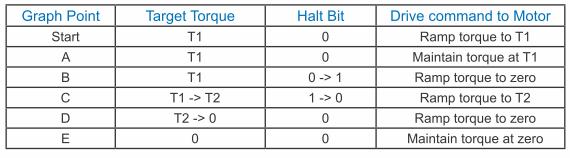
18 Torque Profile Mode General Mode Description Torque Profile mode is a servo-control torque operating mode. It requires knowledge of the Torque Constant of the motor in N m/a. This information can be found in the servo motor print. For Step-Servo products like SS EtherCAT, the motor is step motor which does not have a fixed torque constant. It is not recommended that Step-Servo products are used in Torque Profile mode. Enable Torque Profile Mode To enable Torque Profile Mode, the value 0004h must be written to the mode of operation OD entry, located at dictionary address 6060h. The mode of operation can be verified using OD 6061h - mode of operation display - which is updated when the current operation mode is accepted. Set Running Parameters To operate in Torque Profile mode, the following parameters must be set: Enable Drive Operation After power up or node reset, the drive is in disabled state. The value 0006h must be written to the control word OD entry, located at dictionary address 6040h. This will put the drive into ready to switch on state and is ready to enable drive operation. If the value 0006h is not written to the control word first, the drive operation can not be enabled. To enable drive operation, the value 000Fh must be written to the controlword OD entry, located at dictionary address 6040h. This puts the drive into the Operation Enabled state with no torque applied. It should be noted that both enabling the halt bit and setting the target torque to zero will ramp down the torque applied to the motor according to the torque slope. At the end of the slope no torque will be applied to the motor, allowing the shaft to move freely. Starting/Stopping Torque To start and stop motion, toggle the controlword halt bit (bit 8). When the halt bit is set to 0, motion will start or continue; when the halt bit is set to 1, motion will stop. The bit can be toggled by writing 010Fh and 000Fh to controlword OD entry 6040h. 18
19 Parameter Calculations Example An application requires a torque of 50 oz-in. and a torque slope of 25 oz-in/sec. The motor print lists the Torque Constant of the motor as 0.07N m/a. The N m/a constant given must first be converted into mn m/a, as required by the Torque Constant OD entry. The formula used for this is: As the drive works primarily in N m, the desired 50 oz-in of torque must also be converted into N m, using the conversion factor oz-in/n m. Now, the resultant torque of N m must be converted into mn m, as required by the Target Torque OD entry. The result is a value of 353 mn m, rounded to the nearest whole number, for the Target Torque OD Entry. Finally, the desired slope must be converted from the given units of oz-in/sec into the required units of mn m/sec. Rounding to the nearest whole number results in a Torque Slope of 177 mn m/sec. Current Verification Example It is important to check that the current required of the drive is within the limits of the servo amplifier. The drive being used, for example, has a continuous rating of 7 amps, and a peak current of 14 amps, which may be held continuously for 2 seconds. This means that a current of 7 amps can be held indefinitely, and currents between 7 and 14 amps may be used in short bursts. Using the target torque and torque constant from the example above the current draw can be checked, as shown: The resultant current, A, is below the 7A continuous current rating of the drive, and well below the peak current rating of 14A. It is possible for the drive to maintain a current of 7A indefinitely, and peak up to 14A for up to two seconds continuously. Values between 7A and 14A may be held proportionally long. 19

20 Torque Profile Mode Torque Profile Mode Example 20
21 Cyclic Synchronous Position mode General Mode Description In this mode the master controller generates a trajectory and sends target position (0x607A) to the drive at every PDO update cycle. The primary feedback from the drive is the actual motor position and optionally, actual motor velocity and torque. Position, velocity, and torque control loops are all closed in the drive which acts as a follower for the position commands. Enable Cyclic Synchronous Position Mode To enable the Cyclic Synchronous Position mode, the value 0008h must be written to the mode of operation OD entry, located at dictionary address 6060h. The mode of operation can be verified using OD 6061h - mode of operation display - which is updated when the current operation mode is accepted. Enable Drive Operation After power up or node reset, the drive is in disabled state. The value 0006h must be written to the control word OD entry, located at dictionary address 6040h. This will put the drive into ready to switch on state and is ready to enable drive operation. If the value 0006h is not written to the control word first, the drive operation can not be enabled. To enable drive operation, the value 000Fh must be written to the controlword OD entry, located at dictionary address 6040h. This puts the drive into Operation Enabled state. 21
22 Cyclic Synchronous Velocity mode General Mode Description In this mode the master controller sends target velocity (0x60FF) to the drive at every PDO update cycle. The primary feedback from the drive is the actual motor position and optionally, actual motor velocity and torque. Velocity and torque control loops are closed in the drive. If necessary, position loop is closed in the master controller. Enable Cyclic Synchronous Velocity Mode To enable the Cyclic Synchronous Velocity mode, the value 0009h must be written to the mode of operation OD entry, located at dictionary address 6060h. The mode of operation can be verified using OD 6061h - mode of operation display - which is updated when the current operation mode is accepted. Enable Drive Operation After power up or node reset, the drive is in disabled state. The value 0006h must be written to the control word OD entry, located at dictionary address 6040h. This will put the drive into ready to switch on state and is ready to enable drive operation. If the value 0006h is not written to the control word first, the drive operation can not be enabled. To enable drive operation, the value 010Fh must be written to the controlword OD entry, located at dictionary address 6040h. This puts the drive into Operation Enabled state, with the motion halted. 22
23 Homing Mode Set Running Parameters Set the homing and index velocities, acceleration/deceleration, offset and home sensor (if required) using OD entries 6099h, 609Ah, 607Ch, and 2001h respectively. Note: It is important that the limit switch settings have been defined in configuration software prior to using the CANopen Homing Mode. Enable Homing Mode To enable Homing Mode, the value 0006h must be written to the mode of operation OD entry, located at dictionary address 6060h. The mode of operation can be verified using OD 6061h - mode of operation display - which is updated when the current operation mode is accepted. After power up or node reset, the drive is in disabled state. The value 0006h must be written to the control word OD entry, located at dictionary address 6040h. This will put the drive into ready to switch on state and is ready to enable drive operation. If the value 0006h is not written to the control word first, the drive operation can not be enabled. To put the drive into Operation Enabled Mode, write 000Fh to the controlword OD entry, located at dictionary address 6040h. Starting the Homing Procedure Set the Homing Method required using OD entry 6098h. To start the homing procedure, bit 4 of the controlword OD entry located at dictionary address 6040h, must transition from 0 to 1. The status of the homing procedure can be monitored using the statusword OD entry 6041h. 23


24 Homing Method Diagrams Homing Method 1 Homes to the first index CCW after the CW limit switch is reached. Homing Method 2 Homes to the first index CW after the CCW limit switch is reached. 24


25 Homing Method 3 Homes to the first index CW after the positive home switch changes state; the initial direction of motion is dependent on the state of the home switch. Homing Method 4 Homes to the first index CCW after the positive home switch changes state; the initial direction of motion is dependent on the state of the home switch. 25


26 Homing Method 5 Homes to the first index CCW after the negative home switch changes state; the initial direction of motion is dependent on the state of the home switch. Homing Method 6 Homes to the first index CW after the negative home switch changes state; the initial direction of motion is dependent on the state of the home switch. 26
, and homes to the first index CW of the home switch")

27 Homing Method 7 Starts moving CCW (or CW if the home switch is active), and homes to the first index CW of the home switch transition. Homing Method 8 Starts moving CCW (or CW if the home switch is active), and homes to the first index CCW of the home switch transition. 27


28 Homing Method 9 Starts moving CCW and homes to the first index CW of the home switch transition. Homing Method 10 Starts moving CCW and homes to the first index CCW of the home switch transition. 28
, and homes to the first index CCW of the home switch")

29 Homing Method 11 Starts moving CW (or CCW if the home switch is active), and homes to the first index CCW of the home switch transition. Homing Method 12 Starts moving CW (or CCW if the home switch is active), and homes to the first index CW of the home switch transition. 29


30 Homing Method 13 Starts moving CW and homes to the first index CCW of the home switch transition. Homing Method 14 Starts moving CW and homes to the first index CW of the home switch transition shown above. 30


31 Homing Methods 15 and 16 Homing Methods 15 and 16 are reserved for future expansion. Homing Method 17 Homes to the CW limit switch. Homing Method 18 Homes to the CCW limit switch. 31

32 Homing Methods 19 and 20 Home to the home switch transition. 32

33 Homing Methods 21 and 22 Home to the home switch transition. 33

34 Homing Methods 23 and 24 Home to the home switch transition shown below, and bounce off the CCW limit, if required. 34

35 Homing Methods 25 and 26 Home to the home switch transition shown below, and bounce off the CCW limit, if required. 35

36 Homing Methods 27 and 28 Home to the home switch transition shown below, and bounce off the CW limit, if required. 36

37 Homing Methods 29 and 30 Home to the home switch transition shown below, and bounce off the CW limit, if required. 37


38 Homing Methods 31 and 32 Homing Methods 31 and 32 are reserved for future expansion. Homing Method 33 Homes to the next index pulse CW from the current position. If the CW limit is hit, the drive resets to the CCW limit, and continues searching for a limit in the CW direction. Homing Method 34 Homes to the next index pulse CCW from the current position. If the CCW limit is hit, the drive resets to the CW limit, and continues searching for a limit in the CCW direction. 38

39 Homing Method 35 Takes the current position to be the home position; the Home Offset value is ignored, and the motor does not move at all. 39
40 Q Program Mode General Mode Description In order to expand the functionality of MOONS EtherCAT drives, the Q programming language may be used to execute complex motion profiles that may not be possible within the scope of CiA 402. The Q program must be written and pre-loaded into the EtherCAT drive using Q programmer integrated in the configuration software. Q Program Execution To execute a stored Q program on a single drive, a value of -1 (FFh) must be written to the mode of operation OD entry, located at dictionary address 6060h. The mode of operation can be verified using OD entry 6061h - mode of operation display - which is updated when the current operation mode is accepted. Next, the desired Q segment number, 1-12, must be written to the Q Segment Number register, located at address 2007h. After power up or node reset, the drive is in disabled state. The value 0006h must be written to the control word OD entry, located at dictionary address 6040h. This will put the drive into ready to switch on state and is ready to enable drive operation. If the value 0006h is not written to the control word first, the drive operation can not be enabled. To enable drive operation, a value of 000Fh must be written to the controlword OD entry, located at dictionary address 6040h. This puts the drive into Operation Enabled state and ready to run the Q program. To run the selected Q program, a value of 001Fh must be written to the controlword. The Q program will then run to completion. The Q program may be re-executed by a 0->1 transition of the Q Program start bit (bit 4) in the controlword. To halt execution of a Q program, the halt bit (bit 8) of the controlword must be set to 1. The Q program will halt immediately and start from the beginning the next time a 0->1 transition is seen on the Q Program start bit after the halt bit has been cleared. 40
41 Object Dictionary The most important part of a device profile is the Object Dictionary description. The Object Dictionary is essentially a grouping of objects accessible via the network in an ordered predefined fashion. Each object within the dictionary is addressed using a 16-bit index. Object can be mainly divided into general object (from 0x1000) for EtherCAT communication, CiA402 device profile object (from 0x6000) for CANopen over EtherCAT (CoE), and manufacturer specific object (from 0x2000) exclusively provided by this drive. General Objects 0x1000 Device Type This object describes the type of device and its functionality. It is composed of a 16-bit field which describes the device profile that is used and a second 16-bit field which gives additional information about optional functionality of the device. Var UNSIGNED32 ro no 0x Bit 0~15: Device profile number Bit 16~31: Additional information 0x0192: CiA402 0x0002: Servo Drive 0x1008 Device Name This object provides the name of the device as given by the manufacturer. Var Visible string ro no EtherCAT Drive 0x1009 Hardware Version This object provides the manufacturer hardware version description. Var Visible string ro no A5 0x100A Software Version This object provides the manufacturer software version description. Var Visible string ro no 100I 41
42 0x1018 Identity This object contains general information about the device. Array UNSIGNED32 ro no - Sub Index Name Default Value 00 max sub-index 4 01 Vendor ID 0x Product code 1 03 Revision 1 04 Serial number - 0x1600 ~ 0x1603 RPDO Mapping Parameter This object contains the mapping parameters for the PDOs the device is able to receive. The sub-index 00h contains the number of valid entries within the mapping record. The number of valid object entries shall be the number of the application objects that shall be received with the corresponding RPDO. The sub-index from 01h to number of entries contains the information of the mapped application variables. The object describes the content of the PDO by their index, sub-index and length. The length contains the length of the application object in bit. The length contains the length of the application object in bit. This may be used to verify the mapping. The structure of the entries from sub-index 01h 0Ch is as follows: MSB index (16 bit) sub-index (8 bit) LSB object length (8 bit) 42
43 0x1600 1st Receive PDO Mapping Sub Index 0 Number of entries UNSIGNED8 0 to 12 3 rw no Sub Index 1 Mapping entry 1 UNSIGNED32 0 to 0xFFFFFFFF 0x rw no Sub Index 2 Mapping entry 2 UNSIGNED32 0 to 0xFFFFFFFF 0x607A0020 rw no Sub Index 3 Mapping entry 3 UNSIGNED32 0 to 0xFFFFFFFF 0x60FF0020 rw no Sub Index 4 Mapping entry 4 Sub Index 5 Mapping entry 5 Sub Index 6 Mapping entry 6 Sub Index 7 Mapping entry 7 Sub Index 8 Mapping entry 8 Sub Index 9 Mapping entry 9 Sub Index 10 Mapping entry 10 Sub Index 11 Mapping entry 11 Sub Index 12 Mapping entry 12 43
44 0x1601 2nd Receive PDO Mapping Sub Index 0 Number of entries UNSIGNED8 0 to 12 1 rw no Sub Index 1 Mapping entry 1 UNSIGNED32 0 to 0xFFFFFFFF 0x rw no Sub Index 2 Mapping entry 2 Sub Index 3 Mapping entry 3 Sub Index 4 Mapping entry 4 Sub Index 5 Mapping entry 5 Sub Index 6 Mapping entry 6 Sub Index 7 Mapping entry 7 Sub Index 8 Mapping entry 8 Sub Index 9 Mapping entry 9 Sub Index 10 Mapping entry 10 Sub Index 11 Mapping entry 11 Sub Index 12 Mapping entry 12 44
45 0x1602 3rd Receive PDO Mapping Sub Index 0 Number of entries UNSIGNED8 0 to 12 1 rw no Sub Index 1 Mapping entry 1 UNSIGNED32 0 to 0xFFFFFFFF 0x rw no Sub Index 2 Mapping entry 2 Sub Index 3 Mapping entry 3 Sub Index 4 Mapping entry 4 Sub Index 5 Mapping entry 5 Sub Index 6 Mapping entry 6 Sub Index 7 Mapping entry 7 Sub Index 8 Mapping entry 8 Sub Index 9 Mapping entry 9 Sub Index 10 Mapping entry 10 Sub Index 11 Mapping entry 11 Sub Index 12 Mapping entry 12 45
46 0x1603 4th Receive PDO Mapping Sub Index 0 Number of entries UNSIGNED8 0 to 12 1 rw no Sub Index 1 Mapping entry 1 UNSIGNED32 0 to 0xFFFFFFFF 0x60FE0120 rw no Sub Index 2 Mapping entry 2 Sub Index 3 Mapping entry 3 Sub Index 4 Mapping entry 4 Sub Index 5 Mapping entry 5 Sub Index 6 Mapping entry 6 Sub Index 7 Mapping entry 7 Sub Index 8 Mapping entry 8 Sub Index 9 Mapping entry 9 Sub Index 10 Mapping entry 10 Sub Index 11 Mapping entry 11 Sub Index 12 Mapping entry 12 46
47 0x1A00 ~ 0x1A03 TPDO Mapping Parameter This object contains the mapping for the PDOs the device is able to transmit. The sub-index 00h contains the number of valid object entries within the mapping record. The sub-index from 01h to number of entries contains the information of the mapped application objects. The object describes the content of the PDO by their index, sub-index and length. The length contains the length of the application object in bit. This may be used to verify the mapping. The structure of the entries from sub-index 01h 0Ch is as follows: MSB index (16 bit) sub-index (8 bit) LSB object length (8 bit) 47
48 0x1A00 1st Transmit PDO Mapping Sub Index 0 Number of entries UNSIGNED8 0 to 12 5 rw no Sub Index 1 Mapping entry 1 UNSIGNED32 0 to 0xFFFFFFFF 0x603F0010 rw no Sub Index 2 Mapping entry 2 UNSIGNED32 0 to 0xFFFFFFFF 0x rw no Sub Index 3 Mapping entry 3 UNSIGNED32 0 to 0xFFFFFFFF 0x rw no Sub Index 4 Mapping entry 4 UNSIGNED32 0 to 0xFFFFFFFF 0x606C0020 rw no Sub Index 5 Mapping entry 5 UNSIGNED32 0 to 0xFFFFFFFF 0x60F40020 rw no Sub Index 6 Mapping entry 6 Sub Index 7 Mapping entry 7 Sub Index 8 Mapping entry 8 Sub Index 9 Mapping entry 9 Sub Index 10 Mapping entry 10 Sub Index 11 Mapping entry 11 Sub Index 12 Mapping entry 12 48
49 0x1A01 2nd Transmit PDO Mapping Sub Index 0 Number of entries UNSIGNED8 0 to 12 1 rw no Sub Index 1 Mapping entry 1 UNSIGNED32 0 to 0xFFFFFFFF 0x rw no Sub Index 2 Mapping entry 2 Sub Index 3 Mapping entry 3 Sub Index 4 Mapping entry 4 Sub Index 5 Mapping entry 5 Sub Index 6 Mapping entry 6 Sub Index 7 Mapping entry 7 Sub Index 8 Mapping entry 8 Sub Index 9 Mapping entry 9 Sub Index 10 Mapping entry 10 Sub Index 11 Mapping entry 11 Sub Index 12 Mapping entry 12 49
50 0x1A02 3rd Transmit PDO Mapping Sub Index 0 Number of entries UNSIGNED8 0 to 12 1 rw no Sub Index 1 Mapping entry 1 UNSIGNED32 0 to 0xFFFFFFFF 0x rw no Sub Index 2 Mapping entry 2 Sub Index 3 Mapping entry 3 Sub Index 4 Mapping entry 4 Sub Index 5 Mapping entry 5 Sub Index 6 Mapping entry 6 Sub Index 7 Mapping entry 7 Sub Index 8 Mapping entry 8 Sub Index 9 Mapping entry 9 Sub Index 10 Mapping entry 10 Sub Index 11 Mapping entry 11 Sub Index 12 Mapping entry 12 50
51 0x1A03 4th Transmit PDO Mapping Sub Index 0 Number of entries UNSIGNED8 0 to 12 1 rw no Sub Index 1 Mapping entry 1 UNSIGNED32 0 to 0xFFFFFFFF 0x60FD0020 rw no Sub Index 2 Mapping entry 2 Sub Index 3 Mapping entry 3 Sub Index 4 Mapping entry 4 Sub Index 5 Mapping entry 5 Sub Index 6 Mapping entry 6 Sub Index 7 Mapping entry 7 Sub Index 8 Mapping entry 8 Sub Index 9 Mapping entry 9 Sub Index 10 Mapping entry 10 Sub Index 11 Mapping entry 11 Sub Index 12 Mapping entry 12 51
52 0x1C32 Sync Manager Output Parameter This object is used to configure the output sync manager. 0x1C32 Sync Manager Output Parameter Sub Index 0 Number of entries UNSIGNED8-32 ro no Sub Index 1 Sync type UNSIGNED16-0x0001 rw no Sub Index 2 Cycle time UNSIGNED32-0 ro no Sub Index 4 Sync types supported UNSIGNED16-0x8007 ro no Sub Index 5 Minimum cycle time UNSIGNED32-0 ro no Sub Index 6 Calc and copy time UNSIGNED32-0 ro no Sub Index 8 Get cycle time UNSIGNED16-0 rw no Sub Index 9 Delay time UNSIGNED32-0 ro no Sub Index 10 Sync0 cycle time UNSIGNED32-0 rw no Sub Index 11 SM event missed UNSIGNED16-0 ro no Sub Index 12 Cycle time too small UNSIGNED16-0 ro no Sub Index 32 Sync error BOOL - 0 ro no 52
53 0x1C33 Sync Manager Input Parameter This object is used to configure the input sync manager. 0x1C33 Sync Manager Input Parameter Sub Index 0 Number of entries UNSIGNED8-32 ro no Sub Index 1 Sync type UNSIGNED16-0x0022 rw no Sub Index 2 Cycle time UNSIGNED32-0 ro no Sub Index 4 Sync types supported UNSIGNED16-0x8007 ro no Sub Index 5 Minimum cycle time UNSIGNED32-0 ro no Sub Index 6 Calc and copy time UNSIGNED32-0 ro no Sub Index 8 Get cycle time UNSIGNED16-0 rw no Sub Index 9 Delay time UNSIGNED32-0 ro no Sub Index 10 Sync0 cycle time UNSIGNED32-0 rw no Sub Index 11 SM event missed UNSIGNED16-0 ro no Sub Index 12 Cycle time too small UNSIGNED16-0 ro no Sub Index 32 Sync error BOOL - 0 ro no 53
54 CiA402 Device Profile Objects 0x603F Error Code This object reads back the most recent error code generated by the drive. Var UNSIGNED16 ro yes 0 Two error codes are as below: Error Code 0x7500 0xFFFF Description EtherCAT communication error Drive has alarm. Check specific alarm code at object 0x200F There are two levels of alarms: Fault and Warning. See more details on page 69, object 0x200F. When Fault happens, after the condition that caused the error has been resolved, write 80h to object 0x6040 to clear the error code in object 0x603F and object 0x200F. When Warning happens, after the condition that caused the error has been resolved, write 01h to object 0x2006 to clear the error code in object 0x603F and object 0x200F. 54
55 0x6040 Control Word This object is used to control the state and motion of the drive. It can be used to enable / disable the driver power output, start, and abort moves in all operating modes, and clear fault conditions. Var UNSIGNED16 rw yes 0 The bits of the control word are defined as follows: Details on Bits 0 to 3 and 7 Bit Name 0 Switch On 1 Enable Voltage 2 Quick Stop 3 Enable Operation 4 Operation Mode Specific 5 Operation Mode Specific 6 Operation Mode Specific 7 Fault Reset 8 Halt 9 Operation Mode Specific 10 Reserved 11 Manufacturer Specific 12 Manufacturer Specific 13 Manufacturer Specific 14 Manufacturer Specific 15 Manufacturer Specific Command Bit of Control word Bit 7 Bit 3 Bit 2 Bit 1 Bit 0 Shutdown 0 x Switch on Switch on + Enable operation Disable voltage 0 x x 0 x Quick stop 0 x 0 1 x Disable Operation Enable Operation Fault reset 0 -> 1 x x x x 55
56 Details on Bits 4, 5, 6, 8 and 9 For PP mode Bit Name Value Description 0 4 New Set Point Toggle this bit from 0->1 to clock in a new set point 1 Change Set Point 0 Positioning shall be completed (target reached) before the next one gets started 5 Immediately 1 Next positioning shall be started immediately 0 Target position shall be an absolute value 6 Abs/Rel 1 Target position shall be a relative value 0 Positioning shall be executed or continued 8 Halt 1 Axis shall be stopped The previous set-point will be completed and the motor will come to rest 0 before a new set point is processed Change of 9 The motor will continue at the speed commanded by the previous set Set Point 1 point until it has reached the position commanded by the previous set point, then transition to the speed of the new set point For HM mode Bit Name Value Description Homing 0 Do not start homing procedure 4 Operation Start 1 Start or continue homing procedure 0 Enable bit 4 8 Halt 1 Stop axis For Q mode Bit Name Value Description Q Program 0 4 Toggle this bit from 0->1 to run Q program Start 1 0 Enable bit 4 8 Halt 1 Stop axis 56
57 0x6041 Status Word The object indicates the current state of the drive. It consists of bits that indicate the state according to the drive and operation mode. Var UNSIGNED16 ro yes 0 The bits of the status word are defined as follows: The following bits indicate the status of the device: Bit Name 0 Ready to Switch On 1 Switched On 2 Operation Enabled 3 Fault 4 Voltage Enabled 5 Quick Stop 6 Switch On Disabled 7 Warning 8 Manufacturer Specific 9 Remote 10 Target Reached 11 Internal Limit Active 12 Operation Mode Specific 13 Operation Mode Specific 14 Manufacturer Specific 15 Manufacturer Specific State Bit 6 Bit 5 Bit 3 Bit 2 Bit 1 Bit 0 Not Ready to Switch On 0 x Switch On Disabled 1 x Ready to Switch On Switched On Operation Enabled Fault 0 x Fault Reaction Active 0 x Quick Stop Active
58 Bit 9: Remote This bit indicates Control word has settled. Bit 10: Target Reached If bit 10 is set by the drive, then a set point has been reached (torque, speed or position depending on the modes of operation). The change of a target value by software alters this bit. If quick stop option code is 5, 6, 7 or 8, this bit must be set, when the quick stop operation is finished and the drive is halted. If Halt occurred and the drive has halted then this bit is set too. Bit 11: Internal Limit Active This bit set by the drive indicates that an internal limitation is active (e.g. position error limit). For PP mode Bit Name Value Description Halt (Bit 8 in controlword) = 0: Target position not reached 0 Halt (Bit 8 in controlword) = 1: Axis decelerates 10 Target Reached Halt (Bit 8 in controlword) = 0: Target position reached 1 Halt (Bit 8 in controlword) = 1: Velocity of axis is 0 0 Previous set point already processed, waiting for new set point 12 Set Point Ack 1 Previous set point still in process, set point overwriting shall be accepted 0 No following error 13 Following Error 1 Following error For PV mode Bit Name Value Description Halt (Bit 8 in controlword) = 0: Target velocity not reached 0 Halt (Bit 8 in controlword) = 1: Axis decelerates 10 Target Reached Halt (Bit 8 in controlword) = 0: Target velocity reached 1 Halt (Bit 8 in controlword) = 1: Velocity of axis is 0 0 Speed is not equal to 0 12 Speed 1 Speed is equal 0 For CSP and CSV modes Bit Name Value Description 0 Unable to reach the target (position/velocity) 10 Target Reached 1 Reached the target (position/velocity) 0 No following error 13 Following Error 1 Following error 58
59 For HM mode Bit Name Value Description Halt (Bit 8 in controlword) = 0: Home position not reached 0 Halt (Bit 8 in controlword) = 1: Axis decelerates 10 Target Reached Halt (Bit 8 in controlword) = 0: Home position reached 1 Halt (Bit 8 in controlword) = 1: Velocity of axis is 0 0 Homing Mode not yet complete 12 Homing Attained 1 Homing Mode carried out successfully 0 No homing error 13 Homing Error 1 Homing error For Q program mode Bit Name Value Description Halt (Bit 8 in controlword) = 0: Q program running 0 Halt (Bit 8 in controlword) = 1: Axis decelerates 10 Target Reached Halt (Bit 8 in controlword) = 0: Q program finishes or not started 1 Halt (Bit 8 in controlword) = 1: Velocity of axis is 0 59
60 0x6060 Mode of Operation This object is used to set operation mode. Var INTEGER8 rw yes 0 This drive provides the following operation modes: Value Mode -1 Q Program Mode (MOONS specific) 1 Profile Position Mode (PP) 3 Profile Velocity Mode (PV) 4 Torque Profile Mode (TQ) 6 Homing Mode (HM) 8 Cyclic Synchronous Position Mode (CSP) 9 Cyclic Synchronous Velocity Mode (CSV) 0x6061 Mode of Operation Display This object displays current operation mode of the drive. Definition of value is same as Mode of Operation (0x6060). Var INTEGER8 ro yes 0 0x6064 Position Actual Value This object provides the actual value of the position measured by encoder. The unit of this object is step. Var INTEGER32 ro yes 0 0x6065 Following Error Window This object indicates the configured range of tolerated position values symmetrically to the position demand value. If the position actual value is out of the following error window, a following error (Position Limit) occurs. A following error may occur when a drive is blocked, unreachable profile velocity occurs (Jog mode should be Mode 1), or at wrong closed-loop coefficients. The unit of this object is encoder count. If the value of the following error window is 0, the following control shall be switched off. Var UNSIGNED32 rw no
61 0x606C Velocity Actual Value This object provides the actual velocity value derived from encoder. Var INTEGER32 ro yes 0 The reading value from the drive should be divided by 240 to convert to rps unit. e.g.: The reading value from index 0x606C is 2400, means the actual velocity is 10rps. 0x6071 Target Torque This object is the input value for the torque controller in Torque Profile Mode. This object can only be accessed in Servo (or Step Servo) drive. The unit of this object is mn m. Var INTEGER16 rw yes 0 This object parameters is related to the other torque values, such as Torque Slope (index 0x6087) and Torque Constant (index 0x2005). 0x6073 Max Current This object configures the max current permissible value of the drive. The unit of this object is 0.01Amps. Var UNSIGNED16 rw no - 0x6074 Torque Demand Value This parameter is the output value of the torque limit function (if available within the torque control and power-stage function). This object can only be accessed in Servo (or Step Servo) drive. The unit of this object is mn m. Var UNSIGNED16 ro yes 0 0x6078 Current Actual Value This object refers to the instantaneous current in the motor. This object can only be accessed in Servo (or Step Servo) drive. The unit of this object is 0.01Amps. Var INTEGER16 ro yes 0 61
62 0x607A Target Position This object specifies the target position in Profile Position (PP) mode and Cyclic Synchronous Position (CSP) mode. The unit of this object is step. It is related to electronic gearing setting. It is used as absolute coordinate or relative coordinate depending on the Bit 6 (0x6040.6) setting of the Control Word in the PP mode, and is always used as absolute value in the CSP mode. Var INTEGER32 rw yes 0 0x607C Home Offset This object is the difference between the zero position for the application and the home sensor position (found during homing). During homing the home sensor position is found and once the homing is completed the zero position is offset from the home position by adding the Home Offset to the home position. All subsequent absolute moves shall be taken relative to this new zero position. The unit of this object is step. Var INTEGER32 rw yes 0 0x607E Polarity This object contains two individual bits to set the polarity of position and velocity in their own mode. The bit7 (position polarity bit) indicates the position demand value (related to the target position object 0x607A) shall be multiplied by 1 of by 1. The polarity flag shall have no influence to the homing mode. And the bit6 (velocity polarity bit) indicates the velocity demand value (related to the profile velocity object 0x60FF) shall be multiplied by 1 or -1. Var UNSIGNED8 rw yes 0 Bit 6 7 Detail Position polarity 0=> multiply by 1(default) 1=> multiply by -1 Velocity polarity 0=> multiply by 1(default) 1=> multiply by -1 The position polarity bit shall be used only for profile position (pp) mode. The velocity polarity bit shall be used only for profile velocity (pv) mode. 62
63 0x607F Max Profile Speed This object configures the maximum speed allowed in either direction in a move profile. Var UNSIGNED32 rw yes This object is given the same unit as the objects Velocity Actual Value (index 0x606C) and Profile Velocity (0x60FF). 0x6081 Profile Velocity This object configures the velocity normally attained at the end of the acceleration ramp during a profiled move and is valid for both directions of motion. This object sets the velocity value except the velocity parameter in Profile Velocity mode (pv). Var UNSIGNED32 rw yes 2400 This object is given the same unit as the objects Velocity Actual Value (index 0x606C) and Profile Velocity (0x60FF). 0x6083 Profile Acceleration This object configures the acceleration ramp in a profiled move. Var UNSIGNED32 rw yes 600 The value transmit to (or reading from) drive should be multiplied by 6 (divided by 6) to change to rps/s unit. e.g.: Set the acceleration as 100 rps/s. The value transmit to drive should be x6084 Profile Deceleration This object configures the deceleration ramp in a profiled move. Var UNSIGNED32 rw yes 600 The value transmit to (or reading from) drive should be multiplied by 6 (divided by 6) to change to rps/s unit. e.g.: Set the deceleration as 100 rps/s. The value transmit to drive should be x6087 Torque Slope This object describes the rate of change of torque. The unit of this object is mn m/s. Var UNSIGNED32 rw yes 0 63
64 0x6098 Homing Method This object determines the method that will be used during homing. Var INTEGER8 rw yes 0 Please see the detail described in Homing Mode. 0x6099 Homing Speed This object determines the speeds that will be used during homing. There are two parts to define those speeds. Sub-index 1 to set the speed to search home switch. Sub-index 2 to set the speed to search zero position. Object Type Data Type Access Type Default Value Array UNSIGNED32 rw 0 Sub Index Name PDO Mapping Default Value 00 max sub-index no 2 01 speed during search for switch yes 0 02 speed during search for zero yes 0 This object is given the same unit as the objects Velocity Actual Value (index 0x606C) and Profile Velocity (0x60FF). 0x609A Homing Acceleration This object establishes the acceleration to be used for all accelerations and decelerations with the standard homing modes. Var UNSIGNED32 rw yes 0 The unit is the same as Profile Acceleration/Deceleration objects. 0x60F4 Following Error Actual Value This object displays the actual position error (following error) between the target position and the actual position. The unit of this object is encoder count. Var INTEGER32 ro yes 0 64
STF-EtherCAT User Manual
 STF-EtherCAT User Manual APPLIED MOTION PRODUCTS, INC. 1 Contents Introduction to EtherCAT... 4 Commonly Used Acronyms... 4 Protocol... 5 Logical Addressing...5 Auto Increment Addressing...5 Fixed Node
EtherCAT User Manual. For STF EtherCAT
 EtherCAT User Manual For STF EtherCAT Table of Contents Introduction to EtherCAT... 3 Commonly Used Acronyms...3 Protocol...4 Logical Addressing... 4 Auto Increment Addressing...4 Fixed Node Addressing...4
Tritex II. CANopen - Option
 Tritex II CANopen - Option Contents Contents 2 Introduction... 8 1. CAN basics... 8 1.1. Data Frame... 8 1.2. Error Control... 9 1.3. Baud rate... 9 2. CANopen... 9 3. NMT... 10 3.1. NMT State Machine...
CANopen MANUAL. TMCM axis stepper controller/driver board 2.8A RMS / 24V DC Encoder interface
 CANopen MODULES FOR STEPPER MOTORS MODULES CANopen Firmware Version V3.18 CANopen MANUAL TMCM-351 3-axis stepper controller/driver board 2.8A RMS / 24V DC Encoder interface TMCM-341 3-axis controller board
Applied Motion Products CANopen Manual
 Applied Motion Products CANopen Manual APPLIED MOTION PRODUCTS, INC. Introduction This manual describes Applied Motion Products CANopen implementation of CiA 301 and CiA 402 specifications. It is expected
CANopen. stepim. Reference Manual. Manual Revision: 1.3 Firmware Version:
 CApen Reference Manual stepim Manual Revision: 1.3 Firmware Version: 0.0.2.85 Revision History Document Revision Date Remarks 1.3 Mar. 2016 Update. Firmware 0.0.2.85 1.2 28 Feb. 2016 Update. Firmware
CANopen. Technical Guide for Delta ASDA-A2
 CANopen Technical Guide for Delta ASDA-A2 Version: V1.01 Date: December, 2009 This page intentionally left blank Manual Overview Please include the Manual Number and the Manual Version shown below when
Communications Manual
 Communications Manual MC 5010 MC5005 MC5004 MCS WE CREATE MOTION EN Imprint Version: 2nd edition, 9-12-2016 Copyright by Dr. Fritz Faulhaber GmbH & Co. KG Daimlerstr. 23 / 25 71101 Schönaich All rights
DS402 Implementation on Roboteq Motor Controllers
 DS402 Implementation on Roboteq Motor Controllers V1.0, February 24, 2018 visit www.roboteq.com to download the latest revision of this manual NOTE: DS402 is available since firmware v1.9 beta. Please
CANopen User Guide. Rev for ENGEL devices with CANopen support. ENGEL Elektroantriebe GmbH Am Klingenweg 10 D Walluf
 CANopen User Guide Rev. 2.8 for ENGEL devices with CANopen support ENGEL Elektroantriebe GmbH Am Klingenweg 10 D-65396 Walluf Telefon +49 6123 9942-0 Telefax +49 6123 9942-50 info@engelantriebe.de www.engelantriebe.de
NOVOtechnik. Content. TIM CANopen Gebrauchsanleitung TIM CANopen user manual SIEDLE GRUPPE
 Content 9 CANopen 2 9.1 EDS Files 2 9.2 Features 2 9.2.1 Basic information 2 9.2.2 Basics based on CiA DS-301, V4.02 2 9.2.3 Basics based on CiA DSP-406, V3.2 3 9.2.4 Basics SDO communication 3 9.2.5 Basics
CANopen CFW100. User s Manual. Phone: Fax: Web: -
 CANopen CFW100 User s Manual CANopen User s Manual Series: CFW100 Language: English Document Number: 10002835377 / 00 Publication Date: 06/2014 CONTENTS CONTENTS... 3 ABOUT THE MANUAL... 5 ABBREVIATIONS
Positioning Controller
 Edition December 2008 Positioning Controller Introduction Application Note "Interpolation Position Mode" Edition December 2008 EPOS2 50/5, EPOS Module 36/2 Firmware version 2101h or higher The EPOS2 positioning
CANopen CFW-11. Communication Manual. Phone: Fax: Web:
 Motors Automation Energy Transmission & Distribution Coatings CApen CFW-11 Communication Manual Language: English CApen Communication Manual Series: CFW-11 Language: English Document Number: 0899.5747
LVD Digital Servo Drive
 Digital Servo Drive CApen Reference Manual Revision 2.0 Revision History Document Revision Date Remarks 2.0 Mar. 2012 1.0 Oct. 2011 Initial release Hardware Revision Firmware Revision Software Revision
PLC2 Board Communication Manual CANopen Slave
 PLC2 Board Communication Manual CANopen Slave 02/2006 Series: PLC2 0899.5809 E/3 Contents Contents List of Tables 4 List of Figures 4 About the Manual 5 Abbreviations and Definitions...............................
Motors I Automation I Energy I Transmission & Distribution I Coatings. CANopen CFW500. User s Manual
 Motors I Automation I Energy I Transmission & Distribution I Coatings CANopen CFW500 User s Manual CANopen User s Manual Series: CFW500 Language: English Document Number: 10002253105 / 00 Publication Date:
ABSOLUTE ENCODER MEM-BUS. Instruction Manual
 ABSOLUTE ENCODER MEM-BUS Instruction Manual 1 References ETG.1000.1 Overview ETG.1000.2 Physical Layer service definition and ptocol specification ETG.1000.3 Data Link Layer service definition ETG.1000.4
Positioning Controller
 Positioning Controller Application Note "CANopen Basic Information" Edition February 2006 EPOS 24/1, EPOS 24/5, EPOS 70/10 Firmware version 2000h or higher Introduction The EPOS is a digital positioning
Motors Automation Energy Transmission & Distribution Coatings. Software WSCAN. User's Manual
 Motors Automation Energy Transmission & Distribution Coatings Software WSCAN User's Manual User's Manual Series: WSCAN V2.0X Language: English Publication Date: 11/2010 Content 3 Index 0 Parte I General
NOVOtechnik SIEDLE GRUPPE
 Content 1 CANopen 2 1.1 EDS Files 2 1.2 Features 2 1.2.1 Basic information 2 1.2.2 Basics based on CiA DS-301, V4.2.0 2 1.2.3 Basics based on CiA DSP-406, V3.2 3 1.2.4 Basics SDO communication 3 1.2.5
Linear-Encoder Multi-Sensor CANopen Profile
 Linear-Encoder Multi-Sensor CANopen Profile Technical Information Please keep for further use! Edition date/rev. date: 12.11.2003 Document no./rev. no.: TR - ELA - TI - GB - 0035-01 Software version: CiA
4 Interpolated Position Mode
 In Brief 4 Interpolated Position Mode 4.1 In Brief A wide variety of operating modes permit flexible configuration of drive and automation systems by using positioning, speed and current regulation. The
CANopen. Network configuration. Operating instructions Software. Integration of Bürkert devices in CANopen networks
 CANopen Network configuration Integration of Bürkert devices in CANopen networks Operating instructions Software Content CANopen quick guide 4 I. Setting the "CANopen" bus mode on the device 4 II. Setting
Linear-Encoders CANopen Profile
 TR - ELA - TI - GB - 0039-01 03/30/2016 + 2 Sensors + Position + Speed Linear-Encoders CANopen Profile Technical Information TR-Electronic GmbH D-78647 Trossingen Eglishalde 6 Tel.: (0049) 07425/228-0
Decentralized positioning drives
 Decentralized positioning drives MP-200 _Additional safety instructions _EtherCAT communication _Configuration / Parameterization _Troubleshooting / Diagnosis User Manual Interface TR - EMO - BA - GB -
Commissioning the 9400 Highline TA CiA402 with EtherCAT and Beckhoff NC
 Commissioning the 9400 Highline TA CiA402 with EtherCAT and Beckhoff NC Contents 1. Preface/aim of the Application Report...2 2. Introduction...3 2.1. General information on EtherCAT...3 2.2. General information
hipecs-cio100 CANopen I/O module with 16/16 digital I/O
 General The hipecs-cio100 is a low cost CANopen unit with 16 digital inputs and 16 digital outputs suitable for 24 V DC applications. The I/O s are positive switching and opto-isolated from the bus and
hipecs-cio52 CANopen I/O module with 4 analog outputs
 General The hipecs-cio52 is a low-cost CANopen module with 4 analog output lines. The I/O are isolated from power supply and the CAN bus sub system. Furthermore, the module has an output resolution of
AG05. Actuator with CANopen interface User manual 055/18
 AG05 Actuator with CANopen interface User manual 055/18 Table of contents 1 General Information... 6 1.1 Documentation...6 2 Block Diagram... 6 3 Display and Control Keys... 7 3.1 General...7 3.2 LCD display...7
hipecs-cio55 CANopen I/O module with 4 analog inputs
 General The hipecs-cio55 is a low-cost CANopen module with 4 analog input lines. The I/O are isolated from power supply and the CAN bus sub system. Furthermore, the module has an input resolution of 16
CANopen IO X4 Fact sheet
 CANopen IO X4 Fact sheet Overview The CANopen IO X4 is a very compact and cost effective CANopen IO module featuring a high-density of industrial proven IO's. The module includes a CPU-core including the
Multi-Axis Position Control by EtherCAT Real-time Networking
 Multi-Axis Position Control by EtherCAT Real-time Networking Lecture Topics EtherCAT Applications Overview The EtherCAT Control Approach The EtherCAT Data Processing Time Synchronization Requirements in
Communications Manual MC 5010 MC 5005 MC 5004 MCS RS232 / WE CREATE MOTION
 Communications Manual MC 5010 MC 5005 MC 5004 MCS RS232 / WE CREATE MOTION EN Imprint Version: 15-04-2016 Copyright by Dr. Fritz Faulhaber GmbH & Co. KG Daimlerstr. 23 / 25 71101 Schönaich All rights reserved,
LXM23A CANopen Fieldbus protocol for servo drive Fieldbus manual V2.00,
 Fieldbus protocol for servo drive Fieldbus manual V2.00, 10.2011 www.schneider-electric.com Important information LXM23A CANopen Important information This manual is part of the product. Carefully read
User manual. magnetic absolute positioning drive with AG03
 User manual magnetic absolute positioning drive with interface AG03 1 GENERAL REMARKS...5 1.1 SYMBOLS AND THEIR MEANING...5 1.2 DOCUMENTATION...5 2 FUNCTIONAL DESCRIPTION...6 2.1 SYSTEM STATUS WORD...6
CANopen Vehicle Gateway Software Specifications rev 2.01
 CApen Vehicle Gateway Software Specifications rev 2.01 Page 1 of 136 Revision Date 0.1A Initial Specification 10/21/2003 0.1B Added MTU Emergency and MTU Fault codes 5/25/2004 0.1C Added MTU Communication
CANopen IO X1 Fact sheet
 CANopen IO X Fact sheet Overview The CANopen IO X is a very compact and cost effective CANopen IO module featuring a high-density of industrial proven I/O's. The module includes a CPU-core including the
CAN OPEN DP404 Digital Output
 CAN OPEN DP404 Digital Output Operating Handbook code 85191A Edit. 02-02-2012-ENG Summary 1 Introduction pag. 1 2 Electrical Connections pag. 3 3 Using the transducer pag. 4 4 CAN OPEN Protocol pag. 6
Embedded Motion Control Library
 Embedded Motion Control Library For support mail to: tech-support@smac-mca.nl See also our website: www.smac-mca.com Product Manual Revision 1.3 (Firmware version 2.0) www.ingeniamc.com Embedded Motion
User manual. Actuator with RS485/SIKONETZ5 interface AG03/1
 User manual Actuator with RS485/SIKONETZ5 interface AG03/1 1 General Information... 4 1.1 DOCUMENTATION... 4 2 Block diagram... 4 3 Display and operating elements... 5 3.1 GENERAL INFORMATION... 5 3.2
3 CH Analog Output module / CANopen
 3 CH Analog Output module / CANopen Power Supply 1..4 Vdc, 19..28 Vac Isolation 1,5 kvac (5 way) Accuracy,5% A/D resolution 14 bit Channels 3 Voltage range 1 V Current range..2, 4..2 ma RPDO < 2 ms (-1%
KOLLMORGEN. SERVOSTAR CD. SERCOS IDN Manual M-SS rev. F. Solutions by D A N A H E R M O T I O N
 KOLLMORGEN www.danahermotion.com SERVOSTAR CD Solutions by D A N A H E R M O T I O N SERCOS IDN Manual M-SS-017-05 rev. F Revision History Revision Edition Date Reason for Revision 1 05/01/1999 Initial
Positioning Controllers. Communication Guide. Document ID: rel4896
 Communication Guide MAXPOS Positioning Controllers Edition August 2014 Positioning Controllers Communication Guide Document ID: rel4896 maxon motor ag Brünigstrasse 220 P.O.Box 263 CH-6072 Sachseln Phone
hipecs-cio56 CANopen I/O module with PT100/1000 inputs
 General The hipecs-cio56 is a powerful, low-cost CANopen module for temperature measuring via PT100/1000. According to demands 2-, 3- or 4-wire-connection is usable. Up to 4 channels using 2-wire-connection
AG25, AG26. User manual 225/18
 AG25, AG26 Actuator with User manual interface 225/18 Table of contents 1 General Information... 9 1.1 Documentation...9 2 Displays and operating elements... 9 2.1 General Information...9 2.2 Displays...9
CANopen IO X2 Fact sheet
 CANopen IO X2 Fact sheet Overview The CANopen IO X2 is a very compact and cost effective CANopen IO module featuring a high-density of industrial proven I/O's. The module includes a CPU-core including
OPERATING INSTRUCTIONS. CANopen - Protocol with Device Profile in accordance with CiA DSP 408
 OPERATING INSTRUCTIONS CANopen - Protocol with Device Profile in accordance with CiA DSP 408 Revision 6 Page 1 Inhaltsverzeichnis 1 CANopen Technology 3 1.1 EDS... Files 3 1.2 General... 3 1.3 Technical...
CANOPEN-16DI-16DO-6AIx-4AOx-2E. CANopen IO Module User s Manual
 CANOPEN-16DI-16DO-6AIx-4AOx-2E CApen IO Module User s Manual CApen IO Module User s Manual!!! Warning!!! Cybelec reserves the right to change any information contained in this manual without notice. April
CANopen User manual Website: Technical Support: Skype: Phone: QQ: Technical forum:
 User manual Website: http://www.we-con.com.cn/en Technical Support: support@we-con.com.cn Skype: fcwkkj Phone: 86-591-87868869 QQ: 1043098682 Technical forum: http://wecon.freeforums.net/ 1. Installation
Positioning Controller
 April 2009 Edition Positioning Controller Application Note "Device Programming" April 2009 Edition EPOS 24/1, EPOS 24/5, EPOS 70/10, MCD EPOS 60W, EPOS2 50/5 Firmware version 2000h higher Introduction
ABB AC Brushless Servodrives DGV Converters. CANOpen Guide
 ABB Sace ABB AC Brushless Servodrives DGV Converters CANOpen Guide ABB AC Brushless Servodrives DGV Converters CANOpen Guide MANIU20.0410 E EFFECTIVE: 15.10.2004 SUPERSEDES: 30.09.2004 2003 ABB Sace S.p.a.
AFS60 EtherCAT AFM60 EtherCAT
 OPERATING INSTRUCTIONS AFS60 EtherCAT AFM60 EtherCAT Absolute Encoder GB Operating Instructions This document is protected by the law of copyright. Whereby all rights established therein remain with the
EtherCat for S300/400/600/700
 EtherCat for S300/400/600/700 Communication Profile Fieldbus Interface Edition 10/2007 Keep the manual as a product component during the life span of the product. Pass the manual to future users / owners
Embedded Motion Control Library
 Embedded Motion Control Library Software Manual Revision 1.0 www.ingeniamc.com Embedded Motion Control Library Product manual Copyright and trademarks Copyright 2012 INGENIA CAT, S.L. Scope This document
hipecs-gw30 General Description Features Ordering Information RS232 / CAN - Gateway
 RS232 / CAN - Gateway General The module hipecs-gw30 is a very compact and powerful CANopen / RS232 gateway. The gateway module hipecs-gw30 gives the possibility to integrate devices with RS232 interface
ABSOPOS Series CANopen DS406 V3.1 Operating Manual Configuration and CAN-Bus Coupling
 ABSOPOS Series V. Operating Manual Configuration and CAN-Bus Coupling Index CAN Bus Interface System description Configuration of Node parameter 4 Configuration of Process parameter 4 Emergency-Object
Master Classes. Document: ETG.1500 D (R) Nomenclature: ETG-Number ETG.1500 D (Directive) Version Created by:
 Nomenclature: ETG-Number ETG.1500 D (Directive) Version Created by:") Master Classes Document: ETG.1500 D (R) 1.0.2 Nomenclature: ETG-Number ETG.1500 Type D (Directive) State R (Release) Version 1.0.2 Created by: ETG Contact: info@ethercat.org Filename: ETG1500_D_MasterClasses.docx
Master Classes Document: ETG.1500 D (R) 1.0.2 Nomenclature: ETG-Number ETG.1500 Type D (Directive) State R (Release) Version 1.0.2 Created by: ETG Contact: info@ethercat.org Filename: ETG1500_D_MasterClasses.docx
Technical Documentation 0630
 0630 Digital Pressure Transmitter Protocol 1-6-30-628-058 SUCO Robert Scheuffele GmbH & Co. KG, Keplerstraße 12-14, 74321 Bietigheim-Bissingen, Tel.:+49-7142-597-0, Fax: +49-7142-597-19 Web: www.suco.de,
Contents. Additional Instructions P-3X CANopen
 Page 1 of 24 / 07.04.14 Contents 1. Quick Start Guide... 2 2. Service Data Object (SDO)... 3 2.1 Read Object... 3 2.2 Write Object... 3 2.3 Abort SDO Transfer... 3 2.4 SDO Abort Codes... 4 3. Process Data
EtherCAT Master Cross Platform Stack Application Developers Manual to Product P.4500.xx / P.4501.xx / P
 EtherCAT Master Cross Platform Stack Application Developers Manual to Product P.4500.xx / P.4501.xx / P.4502.01 EtherCAT Master Application Developers Manual Doc. No.: P.4500.21 / Rev. 1.4 Page 1 of 151
CANopen Interface for SG5 and SG7
 CANopen Interface for SG5 and SG7 User Manual This document applies to the following drives: E12x0-xx-xx-xxx (SG5) E14x0-xx-xx-xxx (SG5) C11x0-xx-xx-xxx (SG7) A11x0-xx-xx-xxx (SG7) (with CANopen Interface
User Manual. K Series Encoders with CANopen Interface KXN FE 09 / 2005
 K Series Encoders with CANopen Interface KXN 11278 FE 09 / 2005 User Manual TWK-ELEKTRONIK GmbH PB. 10 50 63 D-40041 Düsseldorf Tel.: +49/211/63 20 67 Fax: +49/211/63 77 05 info@twk.de www.twk.de COPYRIGHT:
User Manual. R Series Encoders with CANopen Interface RNX HE 11 / 2005
 R Series Encoders with CANopen Interface RNX 11197 HE 11 / 2005 User Manual TWK-ELEKTRONIK GmbH PB. 10 50 63 D-40041 Düsseldorf Tel.: +49/211/63 20 67 Fax: +49/211/63 77 05 info@twk.de www.twk.de COPYRIGHT:
Operating Manual. Inferface. CANopen. English
 Operating Manual Inferface CANopen English Disclaimer The information in this brochure corresponds to our current state of knowledge. However, it is not to be understood as a warranty for certain characteristics
Modular Device Profile
 Modular Device Profile Part 6220: IO-Link Master Document: ETG.5001.6220 S (D) V1.0.5 Nomenclature: ETG Number ETG 5001.6220 Type S (Standard) State R (Release) Version V1.0.5 Created by: ETG Contact:
EtherCAT Slave. Protocol API V Hilscher Gesellschaft für Systemautomation mbh
 Protocol API EtherCAT Slave V4.7.0 Hilscher Gesellschaft für Systemautomation mbh www.hilscher.com DOC110909API10EN Revision 10 English 2017-10 Released Public Table of contents 2/207 Table of contents
AN100 v1.4. EtherCAT network synchronization. Distributed clocks
 AN100 v1.4 EtherCAT network synchronization Many EtherCAT systems benefit greatly from a tight synchronization of devices running on the network. Synchronization is particularly important when drives are
BTL7-V50E-... Configuration Manual
 BTL7-V50E-... Manual english www.balluff.com 1 2 3 Notes to the user 4 1.1 Symbols and conventions 4 1.2 Abbreviations 4 1.3 Explanation of the warning 4 Device properties 4 System description 5 3.1 EtherCAT
Anybus -S CANopen. Fieldbus Appendix. ABS-COP-3 Rev HMS Industrial Networks AB. Germany Japan Sweden U.S.A UK
 Fieldbus Appendix Anybus -S CANopen ABS-COP-3 Rev. 2.02 HMS Industrial Networks AB Germany Japan Sweden U.S.A UK + 49-721 - 96472-0 + 81-45 - 478-5340 + 46-35 - 17 29 20 + 1-773 - 404-3486 + 44 (0) 1908-359301
Hexapod Motion Controller with EtherCAT
 Hexapod Motion Controller with EtherCAT Control a 6-Axis Positioning System via Fieldbus Interface C-887.53x Integration into an automation system Synchronous motion in 6 axes Cycle time 1 ms Commanding
Device manual Encoder with CANopen interface RM7 RN7
 Device manual Encoder with CANopen interface RM7 RN7 UK 706362/01 01/2018 Contents 1 Preliminary note................................................. 4 1.1 Symbols used...............................................
CANopen User Manual IE25, IWN
 Inductive Linear Displacement Transducers with CANopen Interface IWN 11307 FE 06 / 2010 CANopen User Manual IE25, IWN TWK-ELEKTRONIK GmbH PB. 10 50 63 D-40041 Düsseldorf Tel.: +49/211/63 20 67 Fax: +49/211/63
CANopen Library User Manual
 CANopen Library User Manual V1.03 June 2010-1 - Table of Contents 1. Introduction... 1 1.1. CANopen architecture... 1 1.2. Object Dictionary setting... 3 1.2.1. Service Data Objects (SDO)... 4 1.2.2. Process
User Manual. NanoCAN. Application for stepper motor controls and Plug & Drive motors (version V )
") User Manual Application for stepper motor controls and Plug & Drive motors (version V2.0.0.1) NANOTEC ELECTRONIC GmbH & Co. KG Kapellenstraße 6 D-85622 Feldkirchen b. Munich, Germany Tel. +49 (0)89-900
User Manual Application for stepper motor controls and Plug & Drive motors (version V2.0.0.1) NANOTEC ELECTRONIC GmbH & Co. KG Kapellenstraße 6 D-85622 Feldkirchen b. Munich, Germany Tel. +49 (0)89-900
PCAN-MicroMod CANopen CANopen Firmware for PCAN-MicroMod. User Manual V1.1.1
 PCAN-MicroMod CANopen CANopen Firmware for PCAN-MicroMod User Manual V1.1.1 Products taken into account Product name Model Part number CANopen Firmware for PCAN-MicroMod CANopen and CiA are registered
SYSTEMS INTELLIGENT SERVO DRIVE. CANopen for CAN and EtherCAT Drives Reference Manual Manual Revision: 2.1 Firmware Version: 1.3.2
 SYSTEMS INTELLIGENT SERVO DRIVE CANopen for CAN and EtherCAT Drives Reference Manual Manual Revision: 2.1 Firmware Version: 1.3.2 www.pbasystems.com.sg Revision History Document Revision Date Remarks
Appendix A: Data Registers
 Appendix A: Data Registers Data registers can be dedicated to a specific purpose, optionally dedicated or continuously available for user data. They can be designated as Read Only or Read & Write. Data
Options for ABB drives, converters and inverters. User s manual FECA-01 EtherCAT adapter module
 Options for ABB drives, converters and inverters User s manual FECA-01 EtherCAT adapter module List of related manuals See section Related manuals on page 16. EtherCAT is registered trademark and patented
User Manual Connection to CAN
 User Manual Connection to CAN Part Number: 80 860.634 Version: 2 Date: 23.11.2005 Valid for: TSwin.net 4.0x TSwin.net 4.1x Version Date Modifications 1 04.07.2005 First edition 2 23.11.2005 Validation
Positioning Controllers. Application Notes. Document ID: rel3986
 Application Notes MAXPOS Positioning Controllers Edition July 2015 Positioning Controllers Application Notes Document ID: rel3986 maxon motor ag Brünigstrasse 220 P.O.Box 263 CH-6072 Sachseln Phone +41
BMS CAN Manual. V2.0, September 3, 2018 Visit to download the latest revision of this manual Copyright 2018 Roboteq, Inc
 BMS CAN Manual V2.0, September 3, 2018 Visit www.roboteq.com to download the latest revision of this manual Copyright 2018 Roboteq, Inc Copyright Roboteq Inc. 2018. All Rights Reserved. Table of Contents
EtherCAT User's Manual. (Version: V1.06)
") (Version: V1.06) Version update history Date Version Description 2012-11-09 V1.00 Initial release. 2013-05-31 V1.01 The section 5.8 Interpolation position mode is added. 2014-02-28 V1.02 Appendix B and
(Version: V1.06) Version update history Date Version Description 2012-11-09 V1.00 Initial release. 2013-05-31 V1.01 The section 5.8 Interpolation position mode is added. 2014-02-28 V1.02 Appendix B and
Firmware Specification
 Firmware Specification EPOS2 Positioning Controllers Edition May 2016 Positioning Controllers Firmware Specification Document ID: rel5466 maxon motor ag Brünigstrasse 220 P.O.Box 263 CH-6072 Sachseln Phone
AXL E EC DI16 M12 6P. Axioline E EtherCAT device, plastic housing, 16 inputs, 24 V DC, M12 fast connection technology. Data sheet.
 Axioline E EtherCAT device, plastic housing, 16 inputs, 24 V DC, M12 fast connection technology Data sheet 8541_en_03 PHOENIX CONTACT 2015-09-10 1 Description The Axioline E device is designed for use
CANopen Firmware. for PCAN-MicroMod. User Manual
 CANopen Firmware for PCAN-MicroMod User Manual Products taken into account Product Name Model Item Number CANopen Firmware for PCAN-MicroMod Last update May 19, 2005 Initial release Windows and MS-DOS
Contents. Additional Instructions MHC-1 CANopen
 Additional Instructions MHC-1 CApen Page 1 of 47 / 01.12.2014 Contents 1. Quick Start Guide... 3 2. Service Object (SDO)... 4 2.1 Read Object... 4 2.2 Write Object... 4 2.3 Abort SDO Transfer... 4 2.4
CANopen Slave. X-gateway Interface Addendum. Doc: HMSI , Rev: Connecting Devices TM
 X-gateway Interface Addendum CANopen Slave Connecting Devices TM HALMSTAD CHICAGO KARLSRUHE TOKYO BEIJING MILANO MULHOUSE COVENTRY PUNE COPENHAGEN HMS Industrial Networks Mailing address: Box 4126, 300
EM3E Series Stepper Drive User Manual
 EM3E Series Stepper Drive User Manual EM3E Passed the ETC Laboratory Conformance Tested EtherCAT is a registered trademark and patented technology, licensed by Beckhoff Automation GmbH, Germany. Thanks
CANopen Interface for SG5, SG6 and SG7
 CANopen Interface for SG5, SG6 and SG7 User Manual This document applies to the following drives: E12x0-xx-xx-xxx (SG5) E14x0-xx-xx-xxx (SG5) E14x0V2-xx-xx-xxx (SG6) C11x0-xx-xx-xxx (SG7) A11x0-xx-xx-xxx
Servo press kit YJKP - Host interface
 Application Note Servo press kit YJKP - Host interface Host interface of the servo press kit YJKP: - Communication possibilities - Workflow - Object directory - Communication protocol - Communication Mobus
Safety PRECAUTIONS. Danger may be present. Read the message and follow the instructions carefully.
 Thank you for using our S100 EtherCAT option module Safety PRECAUTIONS Always follow safety instructions to prevent accidents and potential hazards from occurring. Safety precautions are classified into
SANYO DENKI Servo Amplifier SANMOTION R and Pro-face AGP-3****-CA1M/LT Connection Procedure. Instruction Manual. Version1.0 (
 SANYO DENKI Servo Amplifier SANMOTION R and Pro-face AGP-3****-CA1M/LT Connection Procedure Instruction Manual Version1.0 (2009.2.25) Table of Contents 1 Applicable devices... 1 2 Installation of GP-Pro
The accessories described in this manual are of the highest quality, carefully designed and built in order to ensure excellent performance.
 User Manual INTRODUCTION Thank you for choosing our product. The accessories described in this manual are of the highest quality, carefully designed and built in order to ensure excellent performance.
Accurate Synchronization of EtherCAT Systems Using Distributed Clocks
 Accurate Synchronization of EtherCAT Systems Using Distributed Clocks Joseph E Stubbs, PE EtherCAT Technology Group 12/2010 EtherCAT Technology Group (1) Purpose of this presentation Gain a basic understanding
vacon optec installation manual ethercat option board ac drives
 vacon ac drives optec ethercat option board installation manual vacon 1 TABLE OF CONTENTS Document: DPD01207B Release date : 12/11/14 1. Safety...3 1.1 Danger...3 1.2 Warnings...4 1.3 Earthing and earth
CANopen Fieldbus manual MDrive Motion Control Products
 CANopen Fieldbus manual MDrive Motion Control Products CANopen Fieldbus Manual Date Revision Changes 05/12/2010 R051211 Initial release. This document replaces and supercedes CANopen implementation manual
UNIDRIVE SP AFFINITY DIGITAX ST DIGIDRIVE SK MENTOR MP
 4463 en - 2009.12 / a UNIDRIVE SP AFFINITY DIGITAX ST DIGIDRIVE SK MENTOR MP START Ensure the CT.xml file is in the appropriate folder on the hard drive of the master Check the LED status of the SM-EtherCAT
DeviceNet for SERVOSTAR S300/S600/S700
 DeviceNet for SERVOSTAR S300/S600/S700 and DeviceNet HMS Simulator Paul Coughlin DeviceNet DeviceNet is an 8-Byte Field Bus System for medium range industrial I/O control Originally created in 1996 for
nemesys Syringe Pump Firmware Specification
 nemesys Syringe Pump Firmware Specification ORIGINAL MANUAL - FEBRUARY 2016 CETONI GmbH Wiesenring 6 07554 Korbussen Germany T +49 (0) 36602 338-0 F +49 (0) 36602 338-11 E info@cetoni.de www.cetoni.de