AX.25 Link Access Protocol. for Amateur Packet Radio. Version 2.2 Revision: 28 August 2017
|
|
|
- Neal Thornton
- 6 years ago
- Views:
Transcription

1 AX.25 Link Access Protocol for Amateur Packet Radio Version 2.2 Revision: 28 August
2 Copyright (c) 1997 by Tucson Amateur Packet Radio Corporation. Portions Copyright (c) 1984, 1993 by The American Radio Relay League, Inc. Authors: William A. Beech, NJ7P, Douglas E. Nielsen, N7LEM, Jack Taylor, N7OO, Editors: William A. Beech, NJ7P, John Langner, WB2OSZ, John Wiseman, G8BPQ, mailto: Production Editors: Greg Jones, WD5IVD, William A. Beech, NJ7P, Code Implementation: Douglas E. Nielsen, N7LEM, (original code in Borland C which ran on the based TNC-3 which has unfortunately been lost), John Langner, WB2OSZ, mailto:wb2osz@comcast.net (2017 code as part of Direwolf project), John Wiseman, G8BPQ, mailto: john.wiseman@ntlworld.com (2017 code for the BPQ Switch). 2
3 Forward Packet radio has linked many thousands of amateur radio stations together directly and by the packet network. The packet network has grown from a series of digipeaters to a sophisticated global network consisting of several types of nodes, including HF gateways, Internet gateways and satellite links. This progress has happened since the publication of version 2.0 of the AX.25 protocol in 1984 by Terry L. Fox, WB4JFI. A major effort towards updating version 2.0 was published in the 7th Computer Networking Conference by Eric Scace, K3NA, in Additional portions of this update were handed out at the conference. Eric's work is included in this update of the standard, together with protocol improvements that will aid networking and HF users. This document is a revision of the AX.25 Version 2.0 Protocol Standard found on the Internet and available from the American Radio Relay League. The authors of this new version took exception to the use of AX.25; none of the Layer 3 protocols have ever been developed. The authors wish to thank Eric Gustafson, N7CL, and Lyle Johnson, KK7P ex-wa7gxd, for providing the material and encouragement during this development. July 1993 William A. Beech, NJ7P Douglas E. Nielsen, N7LEM Jack Taylor, N7OO This is a new version of the 1998 standard. It has had all figures redone using Microsoft Visio. Errors in the SDL have been corrected. This is a revision of the 1998 standard. It has revised text and SDL implementing changes found necessary by individuals implementing this protocol. The authors wish to thank John Langner, WB2OSZ, and John Wiseman, G8BPQ, for their feedback as they coded stacks to implement AX.25 Version
4 Preface This document is the fourth edition of the AX.25 Amateur Packet Radio Link Layer Protocol (Version 2.2, 1996) published by the American Radio Relay League (ARRL) and the Tucson Amateur Packet Radio Corporation (TAPR). In July, 1984, the Administrative Council of the International Amateur Radio Union (IARU) met in Paris and designated the ARRL as the international clearinghouse for information relating to packet radio, with a view towards encouraging common standards and regulations. This document defines a protocol used between two amateur radio stations in a point-to-point or networked communications environment. The protocol specifies only link layer and physical layer functions. It is not intended to specify any upper-layer protocol other than certain interface requirements to and from other layers. This protocol recognizes and accommodates the uniqueness of the amateur radio operating environment This document goes a step beyond most international standards by making the System Description Language (SDL), included in Appendix C, the basis for the standard. The SDL takes precedence over the text of this document and should be used to resolve any apparent discrepancies between the two. The SDL is a much clearer description of the protocol than the verbal text. 4
5 Table of Contents Contents 1 Abstract General Concepts and Terminology Basic Concepts AX.25 Model Data-Link Service Access Point Segmenter/Reassembler Data Link Management Data Link Link Multiplexer Physical System Description Language Frame Structure Flag Field Address Field Control Field PID Field Information Field Bit Stuffing Frame-Check Sequence Order of Octet and Bit Transmission Invalid Frames Frame Abort Inter-Frame Time Fill Address-Field Encoding Non-repeater Address-Field Encoding Destination Subfield Encoding Source Subfield Encoding Layer 2 Repeater Address Encoding Multiple Repeater Operation
6 4 Elements of Procedure and Formats of Fields General Control Fields Control-Field Formats Control-Field Parameters Control-Field Coding for Commands and Responses Information Command Frame Control Field Supervisory Frame Control Field Unnumbered Frame Control Fields Link Error Reporting and Recovery TNC Busy Condition Send Sequence Number Error Reject (REJ) Recovery Selective Reject (SREJ) Recovery Timeout Error Recovery Invalid Frame or FCS Error Elements for Layer-to-Layer Communication Layer 3 Entity < > Management Data-link State Machine Management Data-Link State Machine < > Link Multiplexer State Machine Layer 3 Entity < > Data-Link State Machine Data-Link State Machine < > Link Multiplexer State Machine Link Multiplexer State Machine < > Physical State Machine Physical State Machine < > Hardware Description of AX.25 Procedures Address Field Operation Address Information Command/Response Procedure Poll/Final (P/F) Bit Procedures Procedures for Link Set-Up and Disconnection AX.25 Link Connection Establishment Parameter Negotiation Phase Information-Transfer Phase Link Disconnection
7 6.3.5 Disconnected State Collision Recovery Connectionless Operation Procedures for Information Transfer Sending I Frames Receiving I Frames Priority Acknowledge Reception of Out-of-Sequence Frames Reception of Incorrect Frames Receiving Acknowledgement Receiving REJ Receiving an SREJ Receiving an RNR Frame Sending a Busy Indication Waiting Acknowledgement Resetting Procedure Disassembler/Reassembler List of System Defined Parameters Timers Parameters Appendix A - Glossary Appendix B - References Appendix C1 - Introduction to System Description Language C1.1 Principles of Extended Finite State Machines C1.2 SDL Symbol Definition Appendix C2a - Simplex Physical Layer State Machines C2a.1 Interaction with the Link Multiplexer C2a.2 Interface to the Hardware C2a.3 Internal Operation of the Machine Appendix C2b - Duplex Physical Layer State Machines C2b.1 Interaction with the Link Multiplexer C2b.2 Interface to the Hardware C2b.3 Internal Operation of the Machine
8 Appendix C3 - Link Multiplexer State Machine C3.1 Interaction with the Data-Link State Machine C3.2 Interaction with the Physical Layer State Machine C3.3 Internal Operation of the Machine Appendix C4 - Data-Link State Machine C4.1 Interaction with the Data-Link Service Access Point C4.2 Interaction with the Link Multiplexer State Machine C4.3 Internal Operation of the Machine Appendix C5 - Management Data Link State Machine C5.1 Interaction with the Data Link Service Access Point C5.2 Interaction with the Link Multiplexer State Machine C5.3 Internal Operation of the Machine Appendix C6 - Segmenter/Reassembler C6.1 Segmenter State Machine C6.2 Reassembler State Machine C6.3 Internal Operation of the Machine C6.3.1 Internal Operation of the Segmenter State Machine C6.3.2 Internal Operation of the Reassembler State Machine C6.4 Final Observations Appendix D - Data Link Service Access Point and Primitives D.1 Model of a Data-Link Connection D.2 Queue Model Concepts D.3 DLC Establishment D.4. Data Transfer D.5 DLC Release
9 No table of figures entries found. Figures 9
10 1 Abstract This document details AX.25 version 2.2 digital communication standard. The objective of this standard is to ensure link-layer compatibility between stations. This document is intended to assist the designers and users of amateur packet radio equipment by providing a high-level common reference publication. However, the existence of this protocol is not intended to disparage anyone from designing, marketing or using products, processes or procedures not conforming to the protocol. As with any evolving technical standard, this protocol is subject to periodic review. Interested parties are encouraged to use the latest edition. 1.1 General The amateur radio community has expressed the need and desire to define a protocol that can accept and reliably deliver data over a variety of communications links between two signaling terminals. The AX.25 version 2.2 Link-Layer Protocol provides this service, independent of the existence of any upper layer. This protocol conforms to International Standards Organization (ISO) Information Standards (IS) 3309, 4335 and 7809 High-Level Data Link Control (HDLC) and uses terminology found in these documents. It also follows the principles of Consultative Committee in International Telegraph and Telephone (CCITT) Recommendation Q.920 and Q.921 (LAP-D) in the use of multiple links, distinguished by the address field, on a single shared channel. Parameter negotiation was extracted from ISO IS The data-link service definitions were extracted from ISO IS As defined, this protocol works equally well in either half- or full-duplex amateur radio environments, and has been improved for operation over partially impaired HF circuits. It works equally well for direct connections between two individual amateur packet radio stations, or between an individual station and a multi-port controller. It permits the establishment of more than one link-layer connection per device, if the device is so capable. It also permits self-connections. A self-connection occurs when a device establishes a link to itself using its own address for both the source and destination of the frame. Most link-layer protocols assume that one primary (or master) device (generally called a Data Circuit Terminating Equipment, or DCE), is connected to one or more secondary (or slave) device(s) (usually called a Data Terminating Equipment, or DTE). This type of unbalanced operation is not practical in a shared RF amateur radio environment. Instead, AX.25 assumes that both ends of the link are of the same class, thereby eliminating the two different classes of devices. In this protocol specification, the phrase Terminal Node Controller (TNC) refers to the balanced type of device found in amateur packet radio. Other standards refer to these peer entities as DXEs. 2 Concepts and Terminology 2.1 Basic Concepts ISO has developed a reference model for Open Systems Interconnection (OSI) to better facilitate the interconnection of different types of computing systems. The basic structuring technique in this reference model is known as layering. According to this technique, communication among application processes is viewed as being logically partitioned into an ordered set of layers represented in a vertical sequence as shown in Figure 2.1. Each layer provides a Service Access Point (SAP) for interface to the 10


11 next higher layer. Note that any layer may be a null, where no function or code is provided. Such is the case with the current TAPR TNC-2 equipment, where only Layers 1, 2 and 7 are provided; these comprise the minimum configuration for reliable communications. Figure 2.1 Seven Layer OSI Reference Model. 2.2 AX.25 Model The two lower layers, data link and physical, can be further subdivided into several distinct finite state machines as shown in Figure 2.2. This example shows a single link to the radio port. 11

12 Figure 2.2 AX.25 Finite State Machine Model (Single Link). Figure 2.3 shows an example of multiple links to the radio port. The link multiplexer described in this standard multiplexes multiple data-link connections into one physical connection. A separate data-link machine must be provided for each connection allowed by the implementation. 12
 at the upper boundary of Layer 2. This DLSAP is the point at which the data-link layer provides services to Layer 3.")
13 Figure 2.3 AX.25 Finite State Machine Model (Multiple Stream). 2.3 Data-Link Service Access Point Figures 2.2 and 2.3 indicate a Data-Link Service Access Point (DLSAP) at the upper boundary of Layer 2. This DLSAP is the point at which the data-link layer provides services to Layer 3. Associated with each DLSAP is one or more data-link connection endpoint(s). Entities exist in each layer. Entities may be the Link Multiplexer, Data Link, Management Data Link, or Segmenter. Entities in the same layer, but in different systems that must exchange information to achieve a common objective, are called peer entities. Entities in adjacent layers interact through their common boundary. The services provided by the data-link layer are the combination of the services and functions provided by both the data-link layer and the physical layer. Cooperation between data-link layer entities is governed by a peer-to-peer protocol specific to the layer. For example, when information is to be exchanged between two Layer 3 entities, an association must be established between the entities through the data-link layer using the AX.25 protocol. This association is called a data-link connection. Data-link connections are provided by the data-link layer between two or more DLSAPs. Layer 3 requests services from the data-link layer via command/response interactions known as service primitives. (Similarly, the interaction between the data-link layer and the physical layer also 13
14 occurs via service primitives.) Primitives are discussed in greater detail in Section 5. The primitives that are exchanged between the data-link layer and adjacent layers are of the following four types: REQUEST primitive type: used by a higher layer to request a service from the next lower layer. INDICATION primitive type: used by the next lower layer to provide a service to notify the next higher layer of any specific activity that is service related. The INDICATION primitive may be the result of an activity of the lower layer related to the primitive type REQUEST at the peer entity. RESPONSE primitive type: used by a layer to acknowledge receipt from a lower layer of the primitive type INDICATION. AX.25 does not use the RESPONSE primitive. Actual frames will be sent as shown in the example below with the UA frame. CONFIRM primitive type: used by the upper layer to provide the requested service to confirm that the activity has been completed by the lower layer. Figure 2.4 illustrates the use of the four primitive types in conjunction with the Connect primitive. Figure 2.4 Example Use Of AX.25 Primitive Types. 2.4 Segmenter/Reassembler The Segmenter State Machine accepts input from the higher layer through the DLSAP. If the unit of data to be sent exceeds the limits of an AX.25 Information (I) frame (see Section 4.3.1) or Unnumbered Information (UI) frame (see Section ), the segmenter breaks the unit down into smaller segments for transmission. Incoming segments are reassembled for delivery to the higher layer and passed through the DLSAP. The segmenter passes all other signals unchanged. One segmenter exists per data link. Because a single piece of equipment may have multiple data links in operation simultaneously (e.g., to support multiple higher-layer applications), there can be multiple, independently operating segmenters within the equipment. 14
15 2.5 Data Link The Data-link State Machine is the heart of the AX.25 protocol. The Data-link State Machine provides all logic necessary to establish and release connections between two stations and to exchange information in a connectionless (i.e., via UI frames) and connection-oriented (i.e., via I frames with recovery procedures) manner. One Data-link State Machine exists per data link. Because a single piece of equipment may have multiple data links in operation simultaneously (e.g., to support multiple higher layer applications), there can be multiple, independently operating data-link machines within the equipment. 2.6 Management Data Link The Management Data-link State Machine provides for the parameter negotiation of the AX.25 protocol. The Management Data-link State Machine provides all logic necessary to negotiate operating parameters between two stations. One Management Data-link State Machine exists per data link. Because a single piece of equipment may have multiple data links in operation simultaneously (e.g., to support multiple higher layer applications), there can be multiple, independently operating management data-link machines within the equipment. 2.7 Link Multiplexer The Link Multiplexer State Machine allows one or more data links to share the same physical (radio) channel. The Link Multiplexer State Machine provides the logic necessary to give each data link an opportunity to use the channel, according to the rotation algorithm embedded within the link multiplexer. One Link Multiplexer State Machine exists per physical channel. If a single piece of equipment has multiple physical channels operating simultaneously, then an independently operating Link Multiplexer State Machine exists for each channel. 2.8 Physical The Physical State Machine manipulates the radio transmitter and receiver. One Physical State Machine exists per physical channel. Because different types of radio channel operations are used, the Physical State Machine exists in different forms. Each form hides the peculiar characteristics of each radio channel from the higher layer state machines. Two Physical State Machines have been defined in this standard: simplex and full duplex Physical State Machines. 2.9 System Description Language Each of the above finite state machines is described in the System Description Language in Appendix C. 3 Frame Structure Link layer packet radio transmissions are sent in small blocks of data, called frames. There are three general types of AX.25 frames: Information frame (I frame) 15
16 Supervisory frame (S frame) Unnumbered frame (U frame) Each frame is made up of several smaller groups, called fields. Figures 3.1a and 3.1b illustrate the three basic types of frames. Note that the first bit to be transmitted is on the left side. Flag Address Control Info FCS Flag /224 Bits 8/16 Bits N*8 Bits 16 Bits Figure 3.1a U and S Frame Construction. Flag Address Control PID Info FCS Flag /224 Bits 8/16 Bits 8 Bits N*8 Bits 16 Bits Figure 3.1b Information Frame Construction. Where: The Info field exists only in certain frames (Section 4.4.3) FCS is the Frame Check Sequence field (Section 4.4.6) PID is the Protocol Identifier field (Section 3.4) Each field is made up of an integral number of octets (8-bit byte of binary data) and serves the specific function outlined below. All fields except the Frame Check Sequence (FCS) are transmitted low-order bit first. FCS is transmitted bit 15 first. 3.1 Flag Field The flag field is one octet long. Because the flag delimits frames, it occurs at both the beginning and end of each frame. Two frames may share one flag, which would denote the end of the first frame and the start of the next frame. A flag consists of a zero followed by six ones followed by another zero, or (7E hex). As a result of bit stuffing (see Section 3.6), this sequence is not allowed to occur anywhere else inside a complete frame. 3.2 Address Field The address field identifies both the source of the frame and its destination. In addition, the address field contains the command/response information and facilities for Layer 2 repeater operation. The encoding of the address field is described in Section Control Field The control field identifies the type of frame being passed and controls several attributes of the Layer 2 connection. It is one or two octets in length; its encoding is discussed in Section
17 3.4 PID Field The Protocol Identifier (PID) field appears in information frames (I and UI) only. It identifies which kind of Layer 3 protocol, if any, is in use. HEX Binary Layer 3 Type ** XX01XXXX AX.25 Layer 3 Implemented ** XX10XXXX AX.25 Layer 3 Implemented 0x ISO 8208/CCITT X.25 PLP 0x Compressed TCP/IP Packet Van Jacobson (RFC 1144) 0x Uncompressed TCP/IP Packet Van Jacobson (RFC 1144) 0x Segmentation Fragment 0xC TEXNET Datagram Protocol 0xC Link Quality Protocol 0xCA Appletalk 0xCB Appletalk ARP 0xCC ARPA Internet Protocol 0xCD ARPA Address Resolution Protocol 0xCE FlexNet 0xCF NET/ROM 0xF No Layer 3 Protocol 0xFF Escape Character Next octet contains more Layer3 protocol Information Figure 3.2 PID Definitions. The PID itself is not included as part of the octet count of the information field. The encoding of the PID is as follows: Where: An X indicates all combinations used. Note: All forms of XX11XXXX and XX00XXXX other than those listed above are reserved at this time for future Layer 3 protocols. The assignment of these formats is subject to mutual agreement among amateur radio operators. It is recommended that the creators of Layer 3 protocols contact the ARRL for suggested encodings. 3.5 Information Field The information (I) field conveys user data from one end of the link to the other. The I fields are allowed in only five types of frames: The I frame The UI frame The XID frame The TEST frame The FRMR frame 17
18 The I field defaults to a length of 256 octets and contains an integral number of octets. These constraints apply prior to the insertion of zero bits as specified in Section 3.6. Any information in the I field is passed along the link transparently, except for the zero-bit insertion (see Section 3.6) necessary to prevent flags from accidentally appearing in the I field. 3.6 Bit Stuffing In order to ensure that the flag bit sequence mentioned above does not appear accidentally anywhere else in a frame, the sending station monitors the bit sequence for a group of five or more contiguous 1 bits. Any time five contiguous 1 bits are sent, the sending station inserts a 0 bit after the fifth 1 bit. During frame reception, any time five contiguous 1 bits are received, a 0 bit immediately following five 1 bits is discarded. 3.7 Frame-Check Sequence The Frame-Check Sequence (FCS) is a sixteen-bit number calculated by both the sender and the receiver of a frame. It ensures that the frame was not corrupted by the transmission medium. The Frame- Check Sequence is calculated in accordance with recommendations in the HDLC reference document, ISO Order of Octet and Bit Transmission The FCS field of an AX.25 frame is sent most-significant bit first. That is bit 15 to bit 0, most significant octet first. All other fields are sent with each octet s least-significant bit first. That is bit 0 to bit 7. Multiple octet fields are sent in ascending order. That is the high-order octet first, the next lower octet next, etc. (little endian). 3.9 Invalid Frames A frame is considered by the link layer to be an invalid frame if it: Consists of less than 136 bits (including the opening and closing flags) Is not bounded by opening and closing flags Is not octet aligned (an integral number of octets) 3.10 Frame Abort If a frame must be prematurely aborted, at least fifteen contiguous 1 s are sent without bit stuffing added Inter-Frame Time Fill Whenever it is necessary for a TNC to keep its transmitter on while not actually sending frames, the time between frames should be filled with contiguous flags Address-Field Encoding The address field of all frames consists of a destination, source and (optionally) eight Layer 2 repeater subfields. Each subfield consists of an amateur call sign and a Secondary Station Identifier (SSID). The call sign is made up of upper-case alpha and numeric ASCII characters only. The SSID is 18
19 a four-bit integer that uniquely identifies multiple stations using the same amateur call sign. The HDLC address field is extended beyond one octet by assigning the least-significant bit of each octet to be an extension bit. The extension bit of each octet is set to 0 to indicate the next octet contains more address information, or to 1, to indicate that this is the last octet of the HDLC address field. To make room for this extension bit, the amateur radio call sign information is shifted one bit left Non-repeater Address-Field Encoding If Layer 2 repeaters are not being used, the address field is encoded as shown in Figure 3.3. The destination address is the call sign and SSID of the amateur radio station to which the frame is addressed. The source address contains the amateur call sign and SSID of the station that sent the frame. These call signs are the call signs of the two ends of a Layer 2 AX.25 link only. Address Field of Frame Destination Address Subfield Source Address Subfield A1 A2 A3 A4 A5 A6 A7 A8 A9 A10 A11 A12 A13 A14 Figure 3.3 Non-Repeater Address-Field Encoding. A1 through A14, above, are the fourteen octets that make up the two address subfields of the address field. The destination subfield is seven octets long (A1 through A7), and is sent first, starting with octet A1. This address sequence provides the receivers of frames time to check the destination address subfield to see if the frame is addressed to them while the rest of the frame is being received. The source address subfield is then sent in octets A8 through A14. Both of these subfields are encoded in the same manner, except that the last octet of the address field has the HDLC address extension bit set. The SSID octet at the end of each address subfield (A7 and A14) contains the SSID and the C bit. The C bits identify command and response frames (see Section 6.1.2). The SSID octet at the end of each optional Layer 2 repeater address subfield (A21 and A28) contains the SSID and the H bit ( [H]asbeen-repeated ). The H bits indicate that the Layer 2 repeater station has repeated the frame (see Section ). Each SSID octet contains two bits that are reserved for future use. 19
20 Figure 3.4 shows a typical AX.25 frame in the non-repeater mode of operation. Octet ASCII Binary Hex Flag none x7E A1 N x98 A2 J x94 A x6E A4 P xA0 A5 space x40 A6 space x40 A7 (SSID) none xE0 A8 N x98 A x6E A10 L x98 A11 E x8A A12 M x9A A13 space x40 A14 (SSID) none x61 Control none x3E PID none xF0 FCS none XXXXXXXX 0xHH FCS none XXXXXXXX 0xHH Flag none x7E Bit Position Figure 3.4 Non-Repeater AX.25 Frame. The frame shown is an I frame, not going through a Layer 2 repeater, from N7LEM (SSID=0) to NJ7P (SSID=0), without a Layer 3 protocol. The P/F bit is set; the receive sequence number [N(R)] is 1; the send sequence number [N(S)] is Destination Subfield Encoding Figure 3.5 shows how an amateur call sign is placed in the destination address subfield, occupying octets A1 through A7. 20
21 Octet ASCII Binary Hex A1 N x98 A2 J x94 A x6E A4 P xA0 A5 space x40 A6 space x40 A7 (SSID) none xE0 SSID Encoding CRRSSSS0 0x98 Bit Position Figure 3.5 Destination Field Encoding. Where: The top octet (A1) is the first octet sent, with bit 0 of each octet being the first bit sent, and bit 7 being the last bit sent. The first (low-order or bit 0) bit of each octet is the HDLC address extension bit, set to zero on all but the last octet in the address field, where it is set to one. The bits marked R are reserved bits. They may be used in an agreed-upon manner in individual networks. When not implemented, they are set to one. The bit marked C is the command/response bit of an AX.25 frame, as outlined in Section The characters of the call sign are standard seven-bit ASCII (upper case only) placed in the leftmost seven bits of the octet to make room for the address extension bit. If the call sign contains fewer than six characters, it is padded with ASCII spaces between the last call sign character and the SSID octet. The 0000 SSID is reserved for the first personal AX.25 station. This provision establishes one standard SSID for normal stations to use for the first station Source Subfield Encoding Figure 3.6 shows how an amateur call sign is placed in the destination address subfield, occupying octets A8 through A14. 21
22 Octet ASCII Binary Hex A8 N x98 A x6E A10 L x98 A11 E x8A A12 M x9A A13 space x40 A14 (SSID) none x00 SSID Encoding CRRSSSS0 Bit Position Figure 3.6 Source Field Encoding. Where: The top octet (A8) is the first octet sent, with bit 0 of each octet being the first bit sent, and bit 7 being the last bit sent. The first (low-order or bit 0) bit of each octet is the HDLC address extension bit, set to zero on all but the last octet in the address field, where it is set to one. The bits marked R are reserved bits. They may be used in an agreed-upon manner in individual networks. When not implemented, they are set to one. The bit marked C is the command/response bit of an LA PA frame, as outlined in Section The characters of the call sign are standard seven-bit ASCII (upper case only) placed in the leftmost seven bits of the octet to make room for the address extension bit. If the call sign contains fewer than six characters, it is padded with ASCII spaces between the last call sign character and the SSID octet. The 0000 SSID is reserved for the first personal AX.25 station. This provision establishes one standard SSID for normal stations to use for the first station Layer 2 Repeater Address Encoding If a frame is to go through Layer 2 amateur packet repeater(s), an additional address subfield is appended to the end of the address field. This additional subfield contains the call sign(s) of the repeater(s) to be used. This allows more than one repeater to share the same RF channel. If this subfield exists, the last octet of the source subfield has its address extension bit set to 0, indicating that more address-field data follows. The repeater address subfield is encoded in the same manner as the destination and source address subfields, except for the most-significant bit in the last octet, called the H bit. As discussed in Section , the H bit indicates whether a frame has been repeated or not. The H bit is set to 0 on frames going to a repeater. The repeater changes the H bit to 1 before it retransmits the frame. Stations monitor and repeat frames that meet the following conditions: The frame is addressed to this station in a repeater address subfield The H bit in its repeater address subfield is 0 All previous H bits are set to one 22
23 Figure 3.7 shows how the repeater address subfield is encoded. Figure 3.8 is an example of a complete frame after being repeated. Octet ASCII Binary Hex A15 N x98 A x6E A17 O x9E A18 O x9E A19 space x40 A20 space x40 A21 (SSID) none xE3 SSID Encoding HRRSSSS1 Bit Position Figure 3.7 Repeater Address Encoding. Where: The top octet is the first octet sent, with bit 0 being sent first and bit 7 sent last of each octet. As with the source and destination address subfields discussed above, bit 0 of each octet is the HDLC Address extension bit, is set to 0 on all but the last address octet, where it is set to 1. The R bits are reserved in the same manner as in the source and destination subfields. The H bit is the has-been-repeated bit. It is set to 0 when a frame has not been repeated, and set to 1 by the repeating station when repeated. 23
24 Octet ASCII Binary Hex Flag none x7E A1 N x98 A2 J x94 A x6E A4 P xA0 A5 space x40 A6 space x40 A7 (SSID) none xE0 A8 N x98 A x6E A10 L x98 A11 E x8A A12 M x9A A13 space x40 A14 (SSID) none x61 A15 N x98 A x6E A17 O x9E A18 O x9E A19 space x40 A20 space x40 A21 (SSID) none xE3 Control none x3E PID none xF0 FCS none XXXXXXXX 0xHH FCS none XXXXXXXX 0xHH Flag none x7E Bit Position Figure 3.8 AX.25 Frame In Repeater Mode. The above frame is the same as shown in Figure 3.3, except for the addition of a repeater address subfield (N7OO, SSID=1). The H bit is set, indicating this frame is from the output of the repeater Multiple Repeater Operation The link-layer AX.25 protocol allows operation through more than one repeater. Up to eight repeaters may be used by extending the repeater address subfield. When there is more than one repeater address, the repeater address immediately following the source address subfield will be considered the address of the first repeater of a multiple-repeater chain. As a frame progresses through a chain of repeaters, each successive repeater will set the H bit in its SSID octet, indicating that the frame has been successfully repeated through it. No other changes to the frame are made (except for the necessary recalculation of the FCS). The destination station can determine the route the frame took to reach it by examining the address field and use this path to return frames. The number of repeater addresses is variable. The last repeater address will have the address 24
25 extension bit of the SSID octet set to 1 indicating the end of the address field. All other address octets will have their address extension bit set to 0. Note that various timers (see Section 6.6.1) may require adjustment to accommodate the additional delays encountered when a frame must pass through a multiple-repeater chain. 4 Elements of Procedure and Formats of Fields 4.1 General The elements of procedure define the command and response frames used on the AX.25 link. Procedures are built from these elements and are described in Section Control Fields The control field identifies the type of frame being sent. The control fields in AX.25 are modeled after the ISO HDLC balanced operation control fields Control-Field Formats The three formats of control fields used in AX.25 are the: Information frame (I frame) Supervisory frame (S frame) Unnumbered frame (U frame) Figures 4.1a and 4.1b illustrate the basic format of the control field associated with each of these three types of frames. The control field can be one or two octets long and may use sequence numbers to maintain link integrity. These sequence numbers may be three-bit (modulo 8) or seven-bit (modulo 128) integers. Control Field Type Control-Field Bits I Frame N(R) P N(S) 0 S Frame N(R) P/F S S 0 1 U Frame M M M P/F M M 1 1 Figure 4.1a Control-Field Formats (Modulo 8). Control Field Type Control-Field Bits I Frame N(R) P N(S) 0 S Frame N(R) P/F S S 0 1 Figure 4.1b Control-Field Formats (Modulo 128). Where: Bit 0 is the first bit sent and bit 7 (or bit 15 for modulo 128) is the last bit sent of the control field. N(S) is the send sequence number (bit 1 is the LSB). 25
26 N(R) is the receive sequence number [bit 5 (or bit 9 for modulo 128) is the LSB]. The S bits are the supervisory function bits; their encoding is discussed in Section The M bits are the unnumbered frame modifier bits; their encoding is discussed in Section The P/F bit is the Poll/Final bit. The P/F bit is used in all types of frames. The P/F bit is also used in a command (poll) mode to request an immediate reply to a frame. The reply to this poll is indicated by setting the response (final) bit in the appropriate frame. Only one outstanding poll condition per direction is allowed at a time. The procedure for P/F bit operation is described in Section Information-Transfer Format All I frames have bit 0 of the control field set to 0. N(S) is the sender s send sequence number (the send sequence number of this frame). N(R) is the sender s receive sequence number (the sequence number of the next expected receive frame). These numbers are described in Section Supervisory Format Supervisory frames have bit 0 of the control field set to 1, and bit 1 of the control field set to 0. S frames provide supervisory link control such as acknowledging or requesting retransmission of I frames, and link-layer window control. Because S frames do not have an information field, the sender s send variable and the receiver s receive variable are not incremented for S frames Unnumbered Format Unnumbered frames have both bits 0 and 1 of the control field set to 1. U frames are responsible for maintaining additional control over the link beyond what is accomplished with S frames. U frames are responsible for establishing and terminating link connections. U frames also allow for the transmission and reception of information outside of the normal flow control. Some U frames may contain both information and PID fields Control-Field Parameters Sequence Numbers If modulo 8 operation is in effect (the default), an I frame is assigned a sequential number from 0 to 7. This step allows up to seven outstanding I frames per Layer 2 connection at one time. If modulo 128 operation is in effect, an I frame is assigned a sequential number between 0 and 127. This step allows up to 127 outstanding I frames per Layer 2 connection at one time Send State Variable V(S) The send state variable exists within the TNC and is never sent. It contains the next sequential number to be assigned to the next transmitted I frame. This variable is updated with the transmission of each I frame Send Sequence Number N(S) The send sequence number is found in the control field of all I frames. It contains the sequence number of the I frame being sent. Just prior to the transmission of the I frame, N(S) is updated to equal the send state variable. 26
27 Receive State Variable V(R) The receive-state variable exists within the TNC. It contains the sequence number of the next expected received I frame. This variable is updated upon the reception of an error-free I frame whose send sequence number equals the present received state variable value Received Sequence Number N(R) The received sequence number exists in both I and S frames. Prior to sending an I or S frame, this variable is updated to equal that of the received state variable, thus implicitly acknowledging the proper reception of all frames up to and including N(R) Acknowledge State Variable V(A) The acknowledge-state variable exists within the TNC and is never sent. It contains the sequence number of the last frame acknowledged by its peer [V(A)-1 equals the N(S) of the last acknowledged I frame]. 4.3 Control-Field Coding for Commands and Responses Information Command Frame Control Field The information (I) command transfers sequentially-numbered frames containing an information field across a data link. The information-frame control field is encoded as shown in Figures 4.2a and 4.2b. These frames are sequentially numbered by the N(S) subfield to maintain control of their passage over the link-layer connection. Control Field Type Control-Field Bits I Frame N(R) P N(S) 0 Figure 4.2a I Frame Control Field (Modulo 8). Control-Field Bits Control Field Type I Frame N(R) P N(S) 0 Figure 4.2b I Frame Control Field (Modulo 128) Supervisory Frame Control Field The supervisory frame control fields are encoded as shown in Figures 4.3a and 4.3b. 27
28 Control-Field Type Control-Field Bits Receive Ready (RR) N(R) P/F Receive Not Ready (RNR) N(R) P/F Reject (REJ) N(R) P/F Selective Reject (SREJ) N(R) P/F Figure 4.3a S Frame Control Fields (Modulo 8). Control-Field Type Control-Field Bits Receive Ready (RR) N(R) P/F Receive Not Ready (RNR) N(R) P/F Figure 4.3b S Frame Control Fields (Modulo 128). Where: RR Receive Ready - System Ready To Receive. RNR Receive Not Ready - TNC Buffer Full. REJ Reject Frame - Out of Sequence or Duplicate. SREJ Selective Reject - Request single frame repeat Receive Ready (RR) Command and Response Receive Ready accomplishes the following indicates that the sender of the RR is now able to receive more I frames and acknowledges properly received I frames up to, and including N(R)-1. It also clears a previously set busy condition created by an RNR command having been sent. The status of the TNC at the other end of the link can be requested by sending an RR command with the P-bit set to one Receive Not Ready (RNR) Command and Response Receive Not Ready indicates to the sender of I frames that the receiving TNC is temporarily busy and cannot accept any more I frames. Frames up to N(R)-1 are acknowledged. Frames N(R) and above that may have been transmitted are discarded and must be retransmitted when the busy condition clears. The RNR condition is cleared by the sending of a UA, RR, REJ or SABM(E) frame. The status of the TNC at the other end of the link is requested by sending an RNR command frame with the P bit set to one Reject (REJ) Command and Response The reject frame requests retransmission of I frames starting with N(R). Any frames sent with a sequence number of N(R)-1 or less are acknowledged. Additional I frames which may exist may be appended to the retransmission of the N(R) frame. Only one reject frame condition is allowed in each direction at a time. The reject condition is cleared by the proper reception of I frames up to the I frame that caused the reject condition to be initiated. The status of the TNC at the other end of the link is requested by sending a REJ command frame with the P bit set to one. 28
29 Selective Reject (SREJ) Command and Response The selective reject, SREJ, frame is used by the receiving TNC to request retransmission of the single I frame numbered N(R). If the P/F bit in the SREJ frame is set to 1, then I frames numbered up to N(R)-1 inclusive are considered as acknowledged. However, if the P/F bit in the SREJ frame is set to 0, then the N(R) of the SREJ frame does not indicate acknowledgement of I frames. Each SREJ exception condition is cleared (reset) upon receipt of the I frame with an N(S) equal to the N(R) of the SREJ frame. A receiving TNC may transmit one or more SREJ frames, each containing a different N(R) with the P bit set to 0, before one or more earlier SREJ exception conditions have been cleared. However, a SREJ is not transmitted if an earlier REJ exception condition has not been cleared as indicated in Section (To do so would request retransmission of an I frame that would be retransmitted by the REJ operation). Likewise, a REJ frame is not transmitted if one or more SREJ exception conditions have not been cleared as indicated in Section I frames transmitted following the I frame indicated by the SREJ frame are not retransmitted as the result of receiving a SREJ frame. Additional I frames awaiting initial transmission may be transmitted following the retransmission of the specific I frame requested by the SREJ frame Unnumbered Frame Control Fields Unnumbered frame control fields are either commands or responses. Figure 4.4 shows the layout of U frames implemented within this protocol. Control Field Type Type Control-Field Bits Set Asynchronous Balanced Command P Mode Extended (SABME) Set Asynchronous Balanced Command P Mode(SABM) Disconnect (DISC) Command P Disconnect Mode (DM) Response F Unnumbered Acknowledge (UA) Response F Frame Reject (FRMR) Response F Unnumbered Information (UI) Either P/F Exchange Identification (XID) Either P/F Test (TEST) Either P/F Figure 4.4 U Frame Control Fields Set Asynchronous Balanced Mode (SABM) Command The SABM command places two Terminal Node Controllers (TNC) in the asynchronous balanced mode (modulo 8). This is a balanced mode of operation in which both devices are treated as equals or peers. Information fields are not allowed in SABM commands. Any outstanding I frames left when the SABM command is issued remain unacknowledged. The TNC confirms reception and acceptance of a SABM command by sending a UA response frame at the earliest opportunity. If the TNC is not capable of accepting a SABM command, it responds with 29
30 a DM frame if possible Set Asynchronous Balanced Mode Extended (SABME) Command The SABME command places two TNCs in the asynchronous balanced mode extended (modulo 128). This is a balanced mode of operation in which both devices are treated as equals or peers. Information fields are not allowed in SABME commands. Any outstanding I frames left when the SABME command is issued remains unacknowledged. The TNC confirms reception and acceptance of a SABME command by sending a UA response frame at the earliest opportunity. If the TNC is not capable of accepting a SABME command, it responds with a DM frame. A TNC that uses a version of AX.25 prior to v2.2 responds with a FRMR Disconnect (DISC) Command The DISC command terminates a link session between two stations. An information field is not permitted in a DISC command frame. Prior to acting on the DISC frame, the receiving TNC confirms acceptance of the DISC by issuing a UA response frame at its earliest opportunity. The TNC sending the DISC enters the disconnected state when it receives the UA response. Any unacknowledged I frames left when this command is acted upon remain unacknowledged Unnumbered Acknowledge (UA) Response The UA response frame acknowledges the reception and acceptance of a SABM(E) or DISC command frame. A received command is not actually processed until the UA response frame is sent. Information fields are not permitted in a UA frame Disconnected Mode (DM) Response The disconnected mode response is sent whenever a TNC receives a frame other than a SABM(E) or UI frame while in a disconnected mode. The disconnected mode response also indicates that the TNC cannot accept a connection at the moment. The DM response does not have an information field. Whenever a SABM(E) frame is received and it is determined that a connection is not possible, a DM frame is sent. This indicates that the called station cannot accept a connection at that time. While a TNC is in the disconnected mode, it responds to any command other than a SABM(E) or UI frame with a DM response with the P/F bit set to Unnumbered Information (UI) Frame The Unnumbered Information frame contains PID and information fields and passes information along the link outside the normal information controls. This allows information fields to be exchanged on the link, bypassing flow control. Because these frames cannot be acknowledged, if one such frame is obliterated, it cannot be recovered. A received UI frame with the P bit set causes a response to be transmitted. This response is a DM frame when in the disconnected state, or an RR (or RNR, if appropriate) frame in the information transfer state. 30
31 Exchange Identification (XID) Frame The Exchange Identification frame causes the addressed station to identify itself, and to provide its characteristics to the sending station. An information field is optional within the XID frame. A station receiving an XID command returns an XID response unless a UA response to a mode setting command is awaiting transmission, or a FRMR condition exists. ISO 8885 allows for an XID exchange at any time before, during, or after a data link is established. This AX.25 standard only provides for an XID exchange before the data link is established. The XID frame complies with ISO Only those fields applicable to AX.25 are described. All other fields are set to an appropriate value. This implementation is compatible with any implementation which follows ISO Only the general-purpose XID information field identifier is required in this version of AX.25. The information field consists of zero or more information elements. The information elements start with a Format Identifier (FI) octet. The second octet is the Group Identifier (GI). The third and fourth octets form the Group Length (GL). The rest of the information field contains parameter fields. The FI takes the value 82 hex for the general-purpose XID information. The GI takes the value 80 hex for the parameter-negotiation identifier. The GL indicates the length of the associated parameter field. This length is expressed as a two-octet binary number representing the length of the associated parameter field in octets. The high-order bits of length value are in the first of the two octets. A group length of zero indicates the lack of an associated parameter field and that all parameters assume their default values. The GL does not include its own length or the length of the GI. The parameter field contains a series of Parameter Identifier (PI), Parameter Length (PL), and Parameter Value (PV) set structures, in that order. Each PI identifies a parameter and is one octet in length. Each PL indicates the length of the associated PV in octets, and is one octet in length. Each PV contains the parameter value and is PL octets in length. The PL does not include its own length or the length of its associated PI. A PL value of zero indicates that the associated PV is absent; the parameter assumes the default value. A PI/PL/PV set may be omitted if it is not required to convey information, or if present values for the parameter are to be used. The PI/PL/PV fields are placed into the information field of the XID frame in ascending order. There is only one entry for each PI/PL/PV field used. A parameter field containing an unrecognized PI is ignored. An omitted parameter field assumes the currently negotiated value. The parameter fields described below represent the minimum implementation and do not preclude the negotiation of other parameters between consenting stations. The encoding of each PI/PL/PV applicable to AX.25 is detailed in Figure 4.5. Some of the fields are defined in this standard. Only the fields discussed below are required in an implementation that complies with this version of AX
32 Name PI PL Parameter Field Element Type Bit Value Classes of Procedures 2 2 HDLC Optional Functions 3 3 Balanced-ABM E 0 1 Unbalanced-NRM-Primary * E 1 0 Unbalanced-NRM-Secondary * E 2 0 Unbalanced-ARM-Primary * E 3 0 Unbalanced-ARM-Secondary * E 4 0 Half Duplex E 5 0/1 Full Duplex E 6 0/1 Reserved * Reserved * E REJ command/response E 1 0/1 3A SREJ command/response E 2 0/1 4 UI command/response * E SIM command /RIM response * E UP command * E 5 0 7A Basic address * E 6 0 7B Extended address E Delete I response * E Delete I command * E A Modulo 8 E 10 0/1 10B Modulo 128 E 11 0/1 11 RSET command * E TEST command/response E RD response * E A 16-bit FCS E B 32-bit FCS * E A Synchronous Tx E B Start/stop Tx * E C Start/stop Basic Flow E 19 0 Ctl* 15D Start/stop Octet Transparent * E B SREJ Multiframe * E 21 0/1 Reserved * E I Field 5 N Max I fields length Tx B NA B Length Tx (bits)n1*8 * I Field 6 N Max I fields length Rx B NA B Length Rx (bits)n1*8 * Window 7 1 Window Size k (frames) Tx * B B Size Tx 7 0 Window B B Window Size k (frames) Rx * Size Rx 7 0 Ack Timer 9 N Wait for Ack T1 (msec) B NA B Retries 10 N Retry Count N2 B NA B Figure 4.5 Parameter Negotiation - Parameter Field Elements. Note: that Type E is a bit field and Type B is a numeric field of N octets. 32
33 Parameter field elements marked * are defined in ISO They are shown for compatibility purposes only and are not needed to negotiate the features of this version of AX.25. The Classes of Procedures parameter field (PI=2) serves to negotiate half- or full-duplex: Bit 0 is always a 1. Bits 1 through 4 and 7 through 15 are always a 0. Either Bit 5 (half-duplex) or bit 6 (full-duplex), but not both, must be set. If this parameter field is not present, the current values are retained. The default is half-duplex. The HDLC Optional Functions parameter field (PI=3) allows the negotiation of implicit reject (REJ), or selective reject (SREJ), and modulo 8 or 128: Bits 0, 3-6, 8, 9, 12, 14, 16 and are always a 0. Bits 7, 13, 15 and 17 are always a 1. Implicit reject is selected by setting bit 1 and resetting bit 2. Selective reject is selected by resetting bit 1 and setting bit 2. Clearing both bit 1 and 2 is not allowed. Modulo 8 operation is selected by setting bit 10 and resetting bit 11. Modulo 128 operation is selected by setting bit 11 and resetting bit 10. If this parameter field is not present, the current values are retained. The default is selective reject, modulo 128, TEST command/response and multiframe selective REJ. The I Field Length Receive parameter field (PI=6) allows the sending TNC to notify the receiving TNC of the maximum size of an Information field (N1) it will handle without error. A transmitting TNC may not exceed this size, but may send smaller frames. If this field is not present, the current values are retained. The default is 256 octets (2048 bits). The Window Size Receive parameter field (PI=8) allows the sending TNC to notify the receiving TNC of the maximum size of the window (k) it will handle without error. If the TNCs are using modulo 128, this allows the negotiation of a window size less than 127 to conserve memory. If the TNCs are using selective reject or selective reject-reject, the receiving TNC is required to buffer k frames at any time. A transmitting TNC may not exceed this size, but may send fewer frames. If this field is not present, the current values are retained. The default is 4 for modulo 8 and 32 for modulo 128. The Acknowledge Timer parameter field (PI=9) allows the negotiation of the wait for acknowledgement timer (T1). If this field is not present, the current values are retained. The default is 3000 msec. The Retries parameter field (PI=10) allows the negotiation of the retry count (N1). If this field is not present, the current values are retained. The default is 10 retries. A FRMR error condition may be established if the received XID command information field exceeds the maximum defined storage capability of the station, if the receiving station is using AX.25 version 2.0 or earlier versions, or the receiving station wants to use the defaults for version 2.0 or earlier. 33
34 A typical XID frame is shown in Figure 4.6. Octet ID Hex Value Meaning Flag 0x7E Start of frame flag A1 0x98 A2 0x94 A3 0x6E A4 0xA0 From Address (NJ7P-0) A5 0x40 A6 0x40 A7 (SSID) 0xE0 A8 0x98 A9 0x6E A10 0x98 A11 0x8A A12 0x9A To Address (N7LEM-0) A13 0x40 A14 (SSID) 0x61 Control 0xAF XID FI 0x82 Format Indicator GI 0x80 Group Identifier - Parameter Negotiation GL 0x00 Group Length All of the PI/PL/PV Fields (2 0x17 octets) PI 0x02 Parameter Indicator Classes of Procedures PL 0x02 Parameter Length PV 0x20 Parameter Variable Half Duplex, Asynchronous 0x00 Balanced Mode PI 0x03 Parameter Indicator Optional Functions PL 0x03 Parameter Length PV 0x82 Parameter Variable SREJ/REJ, Extended 0xA8 Address, 16-bit FCS, TEST command/response, 0x22 Modulo 128, Synchronous Transmit PI 0x06 Parameter Indicator Rx I Field Length (bits) PL 0x02 Parameter Length PV 0x04 0x00 Parameter Variable 1024 bits (128 octets) PI 0x08 Parameter Indicator Rx Window Size PL 0x01 Parameter Length PV 0x02 Parameter Variable 2 frames PI 0x09 Parameter Indicator Timer T1 PL 0x02 Parameter Length PV 0x10 0x00 Parameter Variable 4096 milliseconds PI 0x0A Parameter Indicator Retries (N1) PL 0x01 Parameter Length PV 0x03 Parameter Variable 3 Retires FCS 0xXX 0xXX Frame Check Sequence (2 octets) Flag 0x7E End of Frame Flag Figure 4.6 Typical XID Frame. 34
35 Test (TEST) Frame The Test command causes the addressed station to respond with the TEST response at the first respond opportunity; this performs a basic test of the data-link control. An information field is optional with the TEST command. If present, the received information field is returned, if possible, by the addressed station, with the TEST response. The TEST command has no effect on the mode or sequence variables maintained by the station. A FRMR condition may be established if the received TEST command information field exceeds the maximum defined storage capability of the station. If a FRMR response is not returned for this condition, a TEST response without an information field is returned. The station considers the data-link layer test terminated on receipt of the TEST response, or when a time-out period has expired. The results of the TEST command/response exchange are made available for interrogation by a higher layer Frame Reject (FRMR) Response Frame The FRMR response is removed from the standard for the following reasons: UI frame transmission was not allowed during FRMR recovery During FRMR recovery, the link could not be reestablished by the station that sent the FRMR The above functions are better handled by simply resetting the link with a SABM(E) + UA exchange An implementation that receives and process FRMRs but does not transmit them is compatible with older versions of the standard SDL is simplified and removes the need for one state in the data-link state machine. This version of AX.25 operates with previous versions of AX.25. It does not generate a FRMR Response frame, but handles error conditions by resetting the link. 4.4 Link Error Reporting and Recovery Several link-layer errors can be recovered without terminating the connection. These error situations may occur as a result of transmission errors or malfunctions within the TNC TNC Busy Condition When a TNC is temporarily unable to receive I frames (e.g., when receive buffers are full), it sends a Receive Not Ready (RNR) frame. This informs the sending TNC that the receiving TNC cannot handle any more I frames at the moment. This receiving TNC clears this condition by the sending a UA, RR, REJ or SABM(E) command frame Send Sequence Number Error If the send sequence number, N(S), of an otherwise error-free received frame does not match the receive state variable, V(R), a send sequence error has occurred. If SREJ has been negotiated and the N(s) is in the range greater-than V(r) and less-than V(r)+k, the information field is saved; otherwise it is discarded. The receiver will not acknowledge this frame or any other I frames until N(S) matches V(R). The control field of the erroneous I frame(s) is accepted so that link supervisory functions such as checking the P/F bit can be performed. Because of this update, the retransmitted I frame may have an 35
36 updated P bit and N(R) Reject (REJ) Recovery The REJ frame requests a retransmission of I frames following the detection of an N(S) sequence error. Only one outstanding sent REJ condition is allowed at a time. This condition is cleared when the requested I frame has been received. A TNC receiving the REJ command clears the condition by resending all outstanding I frames (up to the window size), starting with the frame indicated in N(R) of the REJ frame Selective Reject (SREJ) Recovery The SREJ command/response initiates more-efficient error recovery by requesting the retransmission of a single I frame following the detection of a sequence error. This is an advance over the earlier versions in which the requested I frame was retransmitted together with all additional I frames subsequently transmitted and successfully received. When a TNC sends one or more SREJ commands, each with the P bit set to 0 or 1, or one or more SREJ responses, each with the F bit set to 0, and the sent SREJ conditions are not cleared when the TNC is ready to issue the next response frame with the F bit set to 1, the TNC sends a SREJ response with the F bit set to 1, with the same N(R) as the oldest unresolved SREJ frame. Because an I or S format frame with the F bit set to 1 can cause checkpoint retransmission, a TNC does not send SREJ frames until it receives at least one in-sequence I frame, or it perceives by timeout that the checkpoint retransmission will not be initiated at the remote TNC. With respect to each direction of transmission on the data link, one or more sent SREJ exception conditions from a TNC to another TNC may be established at a time. A sent SREJ exception condition is cleared when the requested I frame is received. The SREJ frame may be repeated when a TNC perceives by timeout that a requested I frame will not be received, because either the requested I frame or the SREJ frame was in error or lost. When appropriate, a TNC receiving one or more SREJ frames initiates retransmission of the individual I frames indicated by the N(R) contained in each SREJ frame. After having retransmitted the above frames, new I frames are transmitted later if they become available. When a TNC receives and acts on one or more SREJ commands, each with the P bit set to 0, or an SREJ command with the P bit set to 1, or one or more SREJ responses each with the F bit set to 0, it disables any action on the next SREJ response frame if that SREJ frame has the F bit set to 1 and has the same N(R) (i.e., the same value and the same numbering cycle) as a previously actioned SREJ frame, and if the resultant retransmission was made following the transmission of the P bit set to a 1. When the SREJ mechanism is used, the receiving station retains correctly-received I frames and delivers them to the higher layer in sequence number order Timeout Error Recovery T1 Timer Recovery If a transmission error causes a TNC to fail to receive (or to receive and discard) a single I frame, or the last I frame in a sequence of I frames, then the TNC does not detect a send-sequence-number error and consequently does not transmit a REJ/SREJ. The TNC that transmitted the unacknowledged I frame(s) following the completion of timeout period T1, takes appropriate recovery action to determine 36
37 when I frame retransmission as described in Section should begin. This condition is cleared by the reception of an acknowledgement for the sent frame(s), or by the link being reset Timer T3 Recovery Timer T3 ensures that the link is still functional during periods of low information transfer. When T1 is not running (no outstanding I frames), T3 periodically causes the TNC to poll the other TNC of a link. When T3 times out, an RR or RNR frame is transmitted as a command with the P bit set, and then T1 is started. When a response to this command is received, T1 is stopped and T3 is started. If T1 expires before a response is received, then the waiting acknowledgement procedure (Section ) is executed Invalid Frame or FCS Error If an invalid frame is received, or a frame is received with an FCS error, that frame is discarded with no further action taken. 5 Elements for Layer-to-Layer Communication Communication between layers is accomplished with primitives. In an abstract way, primitives represent the logical exchange of information and control between the data link and adjacent layers; they do not specify or constrain implementations. Primitives consist of commands and their respective responses associated with the services requested from a lower layer. The general syntax of a primitive is formed by a 2 letter indicator of the level, a hyphen, a label that indicates the function, and a type (Request, Indication or Confirm). For this Standard, the 2 letter level indicators are: DL for communications between Layer 3 and the data-link layer; LM for communications between the data-link layer and the link multiplexer; PH for communications between the link multiplexer and the physical layer; and MDL for communications between Layer 3 and the layer management. HW for the hardware interface to layer Layer 3 Entity < > Management Data-link State Machine Communication between the Layer 3 Entity and the Management Data-link State Machine is characterized by three primitives: MDL-NEGOTIATE Request. The Layer 3 entity uses this primitive to request the Data-link State Machine to notify/negotiate. MDL-NEGOTIATE Confirm. The Management Data-link State Machine uses this primitive to notify the Layer 3 entity that notification/negotiation is complete. MDL-ERROR Indicate. The Management Data-link State Machine uses this primitive to notify the Layer 3 entity that notification/negotiation has failed. 5.2 Management Data-Link State Machine < > Link Multiplexer State Machine Communication between the Management Data-link State Machine and the Link Multiplexer State Machine is characterized by two primitives: LM-DATA Request. The Management Data-link State Machine uses this primitive to pass 37
38 frames of any type (XID, UI, etc.) to the Link Multiplexer State Machine. LM-DATA Indication. The Link Multiplexer State Machine uses this primitive to pass frames of any type (XID, UI, etc.) to the Management Data-link State Machine. 5.3 Layer 3 Entity < > Data-Link State Machine Communication between the Layer 3 Entity and the Data-link State Machine is characterized by thirteen primitives: DL-CONNECT Request. The Layer 3 entity uses this primitive to request the establishment of an AX.25 connection. DL-CONNECT Indication. The Data-link State Machine uses this primitive to indicate that an AX.25 connection has been requested. DL-CONNECT Confirm. The Data-link State Machine uses this primitive to indicate that an AX.25 connection has been made. DL-DISCONNECT Request. The Layer 3 entity uses this primitive to request the release of an AX.25 connection. DL-DISCONNECT Indication. The Data-link State Machine uses this primitive to indicate that an AX.25 connection has been released. DL-DISCONNECT Confirm. The Data-link State Machine uses this primitive to indicate that an AX.25 connection has been released and confirmed. DL-DATA Request. The Layer 3 entity uses this primitive to request the transmission of data using connection-oriented protocol. If necessary, this frame is examined and acted upon by the segmenter. DL-DATA Indication. The reassembler uses this primitive to indicate reception of Layer 3 data using connection oriented protocol. DL-UNIT-DATA Request. The Layer 3 entity uses this primitive to request the transmission of data using connectionless protocol. If necessary, this frame is examined and acted upon by the segmenter. This frame is sent as an UI frame in normal order. DL-UNIT-DATA Indication. The reassembler uses this primitive to indicate reception of Layer 3 data using connectionless protocol. This frame was received as a UI frame. DL-ERROR Indication. The Data-link State Machine uses this primitive to indicate when frames inconsistent with this protocol definition have been received. This includes short frames, frames with inconsistent parameter values, etc. The error indications are discussed in the SDL appendices. DL-FLOW-OFF Request. The Layer 3 entity uses this primitive to temporarily suspend the flow of incoming information. DL-FLOW-ON Request. The Layer 3 entity uses this primitive to resume the flow of incoming information. 5.4 Data-Link State Machine < > Link Multiplexer State Machine Communication between the Data-link State Machine and the Link Multiplexer State Machine is characterized by six primitives: LM-SEIZE Request. The Data-link State Machine uses this primitive to request the Link Multiplexer State Machine to arrange for transmission at the next available opportunity. The Datalink State Machine uses this primitive when an acknowledgement must be made; the exact frame 38
39 in which the acknowledgement is sent will be chosen when the actual time for transmission arrives. LM-SEIZE Confirm. This primitive indicates to the Data-link State Machine that the transmission opportunity has arrived. LM-RELEASE Request. The Link Multiplexer State Machine uses this primitive to stop transmission. LM-EXPEDITED-DATA Request. The data-link machine uses this primitive to request transmission of each digipeat or expedite data frame. LM-DATA Request. The Data-link State Machine uses this primitive to pass frames of any type (SABM, RR, UI, etc.) to the Link Multiplexer State Machine. LM-DATA Indication. The Link Multiplexer State Machine uses this primitive to pass frames of any type (SABM, RR, UI, etc.) to the Data-link State Machine. 5.5 Link Multiplexer State Machine < > Physical State Machine Communication between the Link Multiplexer State Machine and the Physical State Machine is characterized by eight primitives: PH-SEIZE Request. The Link Multiplexer State Machine uses this primitive before each transmission to request access to the radio channel. PH-SEIZE Confirm. The Physical State Machine uses this primitive to confirm that the channel has been seized. PH-RELEASE Request. The Link Multiplexer State Machine uses this primitive to release the radio channel. PH-QUIET Indication. The Physical State Machine uses this primitive to indicate that the channel is not busy. PH-BUSY Indication. The Physical State Machine uses this primitive to indicate that the channel is busy. PH-EXPEDITED-DATA Request. The Link Multiplexer State Machine uses this primitive to request transmission of each digipeat or expedite data frame. PH-DATA Request. The Link Multiplexer State Machine uses this primitive to request transmission of each normal frame. PH-DATA Indication. The Physical State Machine uses this primitive to provide incoming frames to the link multiplexer. 5.6 Physical State Machine < > Hardware Communication between the Physical State Machine and the Hardware is characterized by six primitives: HW-DATA Request. The Physical State Machine uses this primitive to pass frames to send to the hardware. HW-TON Request. The Physical State Machine uses this primitive to tell the hardware to key the transmitter. HW-TOFF Request. The Physical State Machine uses this primitive to tell the hardware to unkey the transmitter. HW-AOS Indication. The hardware uses this primitive to notify the Physical State Machine that modem synchronization, flag fill or frame structure have been detected. 39
40 HW-LOS Indication. The hardware uses this primitive to notify the Physical State Machine that modem synchronization, flag fill or frame structure have been lost. HW-DATA Indication. The hardware uses this primitive to pass frames that have been received to the Physical State Machine. 6 Description of AX.25 Procedures The following paragraphs describe the procedures involved in setting up, using and disconnecting a balanced link between two TNC stations. 6.1 Address Field Operation Address Information All transmitted frames have address fields conforming to Section All frames have both the destination device and the source device addresses in the address field, with the destination address coming first. This allows many links to share the same RF channel. The destination address is always the address of the station(s) for which the frame is intended; the source address contains the address of the device that sent the frame. If point-to-multipoint operation is desired, the destination address can be a group name or club call sign. Operation with destination addresses other than actual amateur call signs is a subject for further study Command/Response Procedure AX.25 implements the command/response information in the address field. The command/response information is conveyed using two bits to maintain compatibility with previous versions of AX.25. An upward-compatible AX.25 TNC communicating with a distant TNC determines if the latter is using an older version of this protocol by testing the command/response bit information located in bit 7 of the SSID octets of both the destination and source address subfields. If both C bits are set to 0, then the distant device is using the older protocol. The newer version of the protocol always has one of these two bits set to 1 and the other bit set to 0, depending on whether the frame is a command or a response. The command/response information is encoded into the address field as shown in Figure 6.1. Implementations of AX.25 prior to version 2.0 defined these bits to be either both 0 or 1. Frame Type Destination SSID C-Bit Source SSID C-Bit Previous Versions 0 0 Command (V2) 1 0 Response (V2) 0 1 Previous Versions 1 1 Figure 6.1 Command/Response Encoding. Because all frames are considered to be either commands or responses, a device always has one of the bits set to 1 and the other bit set to 0. 40
41 The use of the command/response information in AX.25 allows S frames to be either commands or responses. This arrangement helps maintain proper control over the link during the information transfer state. 6.2 Poll/Final (P/F) Bit Procedures The response frame returned by a TNC depends on the previous command received, as described in the following paragraphs. The next response frame returned by the TNC to a SABM(E) or DISC command with the P bit set to 1 is a UA or DM response with the F bit set to 1. The next response frame returned to an I frame with the P bit set to 1, received during the information transfer state, is an RR, RNR or REJ response with the F bit set to 1. The next response frame returned to a supervisory command frame with the P bit set to 1, received during the information transfer state, is an RR, RNR or REJ response frame with the F bit set to 1. The next response frame returned to an S or I command frame with the P bit set to 1, received in the disconnected state, is a DM response frame with the F bit set to 1. The P bit is used in conjunction with the timeout recovery condition discussed in Section When not used, the P/F bit is set to Procedures for Link Set-Up and Disconnection AX.25 Link Connection Establishment To connect to a distant TNC, the originating TNC sends a SABM command frame to the distant TNC and starts its T1 timer. If the distant TNC exists and accepts the connect request, it responds with a UA response frame and resets all of its internal state variables (V(S), V(A) and V(R)). Reception of the UA response frame by the originating TNC causes it to cancel the T1 timer and set its internal state variables to 0. If the distant TNC doesn t respond before T1 times out, the originating TNC resends the SABM frame and starts T1 running again. The originating TNC tries to establish a connection until it has tried unsuccessfully N2 times. N2 is defined in Section If the distant TNC receives a SABM(E) command and cannot enter the indicated state, it sends a DM frame. When the originating TNC receives a DM response to its SABM(E) frame, it cancels its T1 timer and does not enter the information-transfer state. The originating TNC sending a SABM(E) command ignores and discards any frames except SABM, DISC, UA and DM frames from the distant TNC. In response to a received SABM/SABME, frames other than UA and DM are sent only after the link is set up and if no outstanding SABM(E) exists Parameter Negotiation Phase Parameter negotiation occurs only before the connection is made. It is accomplished by sending the XID command frame and receiving the XID response frame. Implementations of AX.25 prior to version 2.2 respond to an XID command frame with a FRMR response frame. The TNC receiving the FRMR uses a default set of parameters compatible with previous versions of AX.25 and a version 2.0 connection is made. The receipt of an XID response from the other station establishes that both stations are using AX.25 version 2.2 or higher and enables the use of the segmenter/reassembler and selective 41
42 reject. A version 2.2 connection is made. This version of AX.25 implements the negotiation or notification of six AX.25 parameters. Notification simply tells the distant TNC some limit that cannot be exceeded. The distant TNC can choose to use the limit or some other value that is within the limits. Notification is used with the Window Size Receive (k) and Information Field Length Receive (N1) parameters. Negotiation involves both TNCs choosing a value that is mutually acceptable. The XID command frame contains a set of values acceptable to the originating TNC. The distant TNC chooses to accept the values offered, or other acceptable values, and places these values in the XID response. Both TNCs set up based on the values used in the XID response. Negotiation is used by Classes of Procedures, HDLC Optional Functions, Acknowledge Timer and Retries. The Classes of Procedure parameter field (PI=2) negotiates half- or full-duplex operation. This reverts to half-duplex if either TNC cannot support full-duplex (i.e., if the XID command requests fullduplex and the receiving TNC can only support half-duplex, it sets the value to half-duplex in the XID response. If this parameter field is not present, the default half-duplex operation is selected. The HDLC Optional Functions parameter field (PI=3) allows the negotiation of implicit reject (REJ), or selective reject (SREJ and modulo 8 or 128. Function reverts to the lesser of the selection offered in the XID command and XID response frames. Ordering is (highest to lowest): selective reject and implicit reject: Modulo 128 and modulo 8. If this parameter field is absent, the default selective reject function and modulo 128 are selected. The I Field Length Receive parameter field (PI=6) allows the sending TNC to notify the receiving TNC of the maximum size of an Information field (N1) it will handle without error. A transmitting TNC may not exceed this size, but may send smaller frames. The Window Size Receive parameter field (PI=8) allows the sending TNC to notify the receiving TNC of the maximum size of the window (k) it will handle without error. If the TNCs are using modulo 128, this allows the negotiation of a window size less than 127 to conserve memory. If the TNCs are using selective reject the receiving TNC is required to buffer k frames at any time. The Acknowledge Timer parameter field (PI=9) allows the negotiation of the Wait for Acknowledgement timer (T1). Function reverts to the greater of the values offered in the XID command and XID response frames. The Retries parameter field (PI=10) allows the negotiation of the retry count (N1). Function reverts to the greater of the values offered in the XID command and XID response frames. Defaults for the negotiated parameters for use with version 2.0 or lower of AX.25 are: Set Half Duplex Set Implicit Reject Modulo = 8 I Field Length Receive = 2048 bits (256 octets) Window Size Receive = 7 Acknowledge Timer = 3000 msec Retries = 10 Defaults for the negotiated parameters for use with version 2.2 of AX.25 are: Set Half Duplex Set Selective Reject Modulo =
43 I Field Length Receive = 2048 bits (256 octets) Window Size Receive = 32 Acknowledge Timer = 3000 msec Retries = Information-Transfer Phase After establishing a link connection, the TNC enters the information-transfer state. In this state, the TNC accepts and transmits I and S frames according to the procedure outlined in Section 6.4. If the TNC receives a SABM(E) command while in the information-transfer state, it follows the resetting procedure outlined in Section Link Disconnection While in the information-transfer state, either TNC may indicate a request to disconnect the link by transmitting a DISC command frame and starting timer T1. After receiving a valid DISC command, the TNC sends a UA response frame and enters the disconnected state. After receiving a UA or DM response to a sent DISC command, the TNC cancels timer T1 and enters the disconnected state. If a UA or DM response is not correctly received before T1 times out, the DISC frame is sent again and T1 is restarted. If this happens N2 times, the TNC enters the disconnected state Disconnected State In the disconnected state, a TNC monitors received commands, reacts to the receipt of a SABM(E) as described in Section 6.3.1, and transmits a DM frame in response to a DISC command. In the disconnected state, a TNC may initiate a link set up as outlined in connection establishment (Section 6.3.1). It may also respond to the receipt of a SABM(E) command and establish a connection, or it may refuse the SABM(E) and send a DM instead. Any TNC receiving a command frame other than a SABM(E) or UI frame with the P bit set to 1 responds with a DM frame with the F bit set to 1. The offending frame is ignored. When the TNC enters the disconnected state after an error condition, or if an internal error has resulted in the TNC being in the disconnected state, the TNC indicates this by sending a DM response rather than a DISC frame and follows the link disconnection procedure outlined in Section The TNC may then try to reestablish the link using the link set up procedure outlined in Section Collision Recovery Collisions in a Half-Duplex Environment Collisions of frames in a half-duplex environment are taken care of by the retry nature of the T1 timer and retransmission count variable. No other special action is required Collisions of Unnumbered Commands. If sent and received SABM(E) or DISC command frames are the same, both TNCs send a UA response at the earliest opportunity, and both devices enter the indicated state. If sent and received SABM(E) or DISC commands are different, both TNCs enter the disconnected state and transmit a DM frame at the earliest opportunity. 43
44 Collision of a DM with a SABM(E) or DISC When an unsolicited DM response frame is sent, a collision between it and a SABM(E) or DISC may occur. In order to prevent this DM from being misinterpreted, all unsolicited DM frames are transmitted with the F bit set to 0. All SABM(E) and DISC frames are sent with the P bit set to 1. This prevents confusion when a DM frame is received Connectionless Operation An additional type of operation exists in amateur radio that is not feasible using Layer 2 connections. This is the round-table operation, in which several amateurs may be engaged in one conversation. This type of operation cannot be accommodated by current AX.25 link-layer connections. The way round-table activity is implemented is technically outside the AX.25 connection, although it still uses the AX.25 frame structure. AX.25 uses a special frame for this operation, the Unnumbered Information (UI) frame. In this type of operation, the destination address has a code word installed in it that prevents users of that specific round-table from seeing all frames going through the shared RF medium. For example, if a group of amateurs are engaged in a round-table discussion about packet radio, they could put PACKET in the destination address; they will receive frames only from others in the same discussion. An added advantage of the use of AX.25 in this manner is that the source of each frame is in the source address subfield; software could be written to automatically display who is making what comments. Since this mode is connectionless, there are no requests for retransmissions of bad frames. Without the handshaking activity of a point-to-point connection, collisions may also occur, with the potential of losing the frames that collided. 6.4 Procedures for Information Transfer Once a connection has been established as outlined above, both TNCs can accept I, S and U frames Sending I Frames Whenever a TNC has an I frame to transmit, it sends the I frame with the N(S) of the control field equal to its current send state variable V(S). After the I frame is sent, the send state variable is incremented by one. If timer T1 is not running, it is started. If timer T1 is running, it is restarted. 44
45 The TNC does not transmit any more I frames if its send state variable equals the last received N(R) from the other side of the link plus k. If the TNC sent more I frames, the flow control window would be exceeded and errors could result. If a TNC is in a busy condition, it may still send I frames as long as the distant TNC is not also busy Receiving I Frames The reception of I frames that contain zero-length information fields is reported to the next layer; no information field will be transferred Not Busy If a TNC receives a valid I frame (one with a correct FCS and whose send sequence number equals the receiver s receive state variable) and is not in the busy condition, it accepts the received I frame, increments its receive state variable, and acts in one of the following manners: If it has an I frame to send, that I frame may be sent with the transmitted N(R) equal to its receive state variable V(R) (thus acknowledging the received frame). Alternately, the TNC may send an RR frame with N(R) equal to V(R), and then send the I frame. If there are no outstanding I frames, the receiving TNC sends an RR frame with N(R) equal to V(R). The receiving TNC may wait a small period of time before sending the RR frame to be sure additional I frames are not being transmitted Busy If the TNC is in a busy condition, it ignores any received I frames without reporting this condition, other than repeating the indication of the busy condition. If a busy condition exists, the TNC receiving the busy condition indication polls the sending TNC periodically until the busy condition disappears. A TNC may poll the busy TNC periodically with RR or RNR frames with the P bit set to Priority Acknowledge This version of AX.25 implements the priority acknowledgement procedure. This feature precludes a non-priority frame from being transmitted during slot 0, the time when the TNC receiving the previous frame would be expected to send an acknowledgement Reception of Out-of-Sequence Frames Implicit Reject (REJ) When an I frame is received with a correct FCS but its send sequence number N(S) does not match the current receiver s receive state variable, the frame is discarded. A REJ frame is sent with a receive sequence number equal to one higher than the last correctly received I frame if an uncleared N(S) sequence error condition has not been previously established. The received state variable and poll bit of the discarded frame is checked and acted upon, if necessary. 45
46 This mode requires no frame queuing and frame resequencing at the receiver. However, because the mode requires transmission of frames that may not be in error, its throughput is not as high as selective reject. This mode is ineffective on systems with long round-trip delays and high data rates Selective Reject (SREJ) When an I frame is received with a correct FCS but its send sequence number N(S) does not match the current receiver s receive state variable, the frame is retained. SREJ frames are sent with a receive sequence number equal to the value N(R) of the missing frame, and P=1 if an uncleared SREJ condition has not been previously established. If an SREJ condition is already pending, an SREJ will be sent with P=0. The received state variable and poll bit of the received frame are checked and acted upon, if necessary. This mode requires frame queuing and frame resequencing at the receiver. The holding of frames can consume precious buffer space, especially if the user device has limited memory available and several active links are operational Reception of Incorrect Frames When a TNC receives a frame with an incorrect FCS, an invalid frame, or a frame with an improper address, that frame is discarded Receiving Acknowledgement Whenever an I or S frame is correctly received, even in a busy condition, the N(R) of the received frame is checked to see if it includes an acknowledgement of outstanding sent I frames. The T1 timer is canceled if the received frame actually acknowledges previously unacknowledged frames. If the T1 timer is canceled and there are still some frames that have been sent that are not acknowledged, T1 is started again. If the T1 timer expires before an acknowledgement is received, the TNC proceeds with the retransmission procedure outlined in Section Receiving REJ After receiving a REJ frame, the transmitting TNC sets it s send state variable to the same value as the REJ frame s received sequence number in the control field. The TNC then retransmits any I frame(s) outstanding at the next available opportunity in accordance with the following: 46
47 a) If the TNC is not transmitting at the time and the channel is open, the TNC may begin retransmission of the I frame(s) immediately. b) If the TNC is operating on a full-duplex channel transmitting a UI or S frame when it receives a REJ frame, it may finish sending the UI or S frame and then retransmit the I frame(s). c) If the TNC is operating in a full-duplex channel transmitting another I frame when it receives a REJ frame, it may abort the I frame it was sending and start retransmission of the requested I frames immediately. d) The TNC may send just the one I frame outstanding, or it may send more than the one indicated if more I frames followed the first unacknowledged frame, provided that the total to be sent does not exceed the flow-control window (k frames). If the TNC receives a REJ frame with the poll bit set, it responds with either an RR or RNR frame with the final bit set before retransmitting the outstanding I frame(s) Receiving an SREJ After receiving a SREJ frame, the transmitting TNC retransmits the individual I frame indicated by the N(R) contained in the SREJ at the next available opportunity. After retransmitting the frame above, new I frames may be retransmitted subsequently if they become available. If the P bit was set, then all frames up to N(R)-1 are acknowledged Receiving an RNR Frame Whenever a TNC receives an RNR frame, it stops transmitting I frames until the busy condition is cleared. If timer T3 expires after the RNR was received, an RR or RNR command with the P bit set is sent to poll the distant TNC of its status; then timer T1 is started. If an RNR frame is received in response to this poll, T1 is stopped and T3 is started again. If no response is received before T1 expires, the waiting acknowledgment procedure (Section ) is performed. If an RR frame is received in response to the poll, then T1 is stopped and the busy condition cleared Sending a Busy Indication Whenever a TNC enters a busy condition, it indicates this by sending an RNR response at the next opportunity. While the TNC is in the busy condition, it may receive and process S frames. If a received S frame has the P bit set to 1, the TNC sends an RNR frame with the F bit set to 1 at the next possible opportunity. To clear the busy condition, the TNC sends either an RR or REJ frame with the received sequence number equal to the current receive state variable, depending on whether the last received I frame was properly received or not Waiting Acknowledgement If the originating TNC s timer T1 expires while awaiting the distant TNC s acknowledgement of an I frame transmitted, the originating TNC restarts timer T1 and transmits an appropriate supervisory command frame (RR or RNR) with the P bit set. If the TNC correctly receives a supervisory response frame with the F bit set and with an N(R) within the range from the last N(R) received to the last N(S) sent plus one, the TNC restarts timer T1 and sets its send state variable V(S) to the received N(R). It may then resume with I frame transmission or retransmission, as appropriate. 47
48 If, on the other hand, the TNC correctly receives a supervisory response frame with the F bit not set, or an I frame or supervisory command frame, and with an N(R) within the range from the last N(R) received to the last N(S) sent plus one, the TNC does not restart timer T1; it uses the received N(R) as an indication of acknowledgement of transmitted I frames up to and including I frame numbered N(R)- 1. If timer T1 expires before a supervisory response frame with the F bit set is received, the TNC retransmits an appropriate supervisory command frame (RR or RNR) with the P bit set. After N2 attempts to get a supervisory response frame with the F bit set from the distant TNC, the originating TNC initiates a link resetting procedure as described in Section Resetting Procedure The link resetting procedure initializes both directions of data flow after a unrecoverable error has occurred. This resetting procedure is used only in the information-transfer state of an AX.25 link. A TNC initiates a reset procedure whenever it receives an unexpected UA response frame, or after receipt of a FRMR frame from a TNC using an older version of the protocol. A TNC resets the link by sending a SABM(E) frame and starting timer T1. After receiving a SABM(E) frame from the previously connected TNC, the receiver sends a UA frame back at the earliest opportunity, sets its send and receive state variables V(S) and V(R) to 0 and stops T1, unless it has sent a SABM(E) or DISC itself. If the UA frame is correctly received by the first TNC, it resets its send and receive state variables V(S) and V(R), and stops timer T1. Any busy condition that previously existed is also cleared. If a DM response is received, the TNC enters the disconnected state and stops timer T1. If timer T1 expires before a UA or DM response frame is received, the SABM(E) is retransmitted and timer T1 restarted. If timer T1 expires N2 times, the TNC enters the disconnected state. Any previously existing link conditions are cleared. Other commands or responses received by the TNC before completion of the reset procedure are discarded. One TNC may request that the other TNC reset the link by sending a DM response frame. After the DM frame is sent, the sending TNC then enters the disconnected state. 6.6 Disassembler/Reassembler The segmenter/reassembler procedure is only enabled if both stations on the link are using AX.25 version 2.2 or higher. The use of the segmenter/reassembler allows the transmission of packets longer than N1 in a simple and clean manner. This adds less than one percent overhead for the standard N1 of 256 bytes. It also adds the ability to send large Level 3 data entities such as IP datagrams as single entities over AX.25. The segmenter is a simple process that divides long data units into smaller segments for transmission, attaching a two-octet header to each segment. At the receiving end, segments are reassembled into the original data unit. Overhead is kept to a minimum throughout; steps are taken to prevent deadlock situations from arising in the buffer management of both stations on the link. The header is illustrated in Figure
49 Bit Position Hex Description x08 PID for segmented frame F X X X X X X X F*128+X F=1 if first segmented frame, F=0 for all other frames; X=number of segments remaining Figure 6.2 Segment Header Format. The reassembler can tell when a segmented frame is received by the PID. If the first segment flag is set, then the amount of buffer space required for the entire frame can be calculated and allocated. If using the segmenter over connectionless service and a segment is lost, error recovery is not done by the reassembler. An error is passed to Layer 3; it is up to Layer 3 to recover. 6.7 List of System Defined Parameters Timers Thirteen timers maintain the integrity of the AX.25 Layer 2 connection and are discussed in the following subsections Acknowledgment Timer T1 T1, the Acknowledgement Timer, ensures that a TNC does not wait indefinitely for a response to a frame it sends. This timer cannot be expressed in absolute time; the time required to send frames varies greatly with the signaling rate used at Layer 1. T1 should take at least twice the amount of time it would take to send maximum length frame to the distant TNC and get the proper response frame back from the distant TNC. This allows time for the distant TNC to do some processing before responding. If Layer 2 repeaters are used, the value of T1 should be adjusted according to the number of repeaters through which the frame is being transferred Response Delay Timer T2 T2, the Response Delay Timer, may optionally be implemented by the TNC to specify a maximum amount of delay to be introduced between the time an I frame is received and the time the resulting response frame is sent. This delay is introduced to allow a receiving TNC to wait a short period of time to determine if more than one frame is being sent to it. If more frames are received, the TNC can acknowledge them at once (up to seven), rather than acknowledging each individual frame. The use of timer T2 is not required; it is simply recommended to improve channel efficiency. Note that to achieve maximum throughput on full-duplex channels, acknowledgments should not be delayed beyond k/2 frames. The k parameter is defined in Section Inactive Link Timer T3 T3, the Inactive Link Timer, maintains link integrity whenever T1 is not running. It is recommended that whenever there are no outstanding unacknowledged I frames or P-bit frames (during the information-transfer state), an RR or RNR frame with the P bit set to 1 be sent every T3 time units to query the status of the other TNC. The period of T3 is locally defined, and depends greatly on Layer 1 operation. T3 should be greater than T1; it may be very large on channels of high integrity. 49
50 Repeater Hang Timer T100 (AXHANG) T100, the Repeater Hang Timer, tracks the amount of time an audio repeater will keep its transmitter keyed after it stops receiving. This timer can increase channel efficiency when an audio repeater is used. If the repeater s transmitter remains keyed, it is not necessary to add AXDELAY to the transmitter keyup time Priority Window Timer T101 (PRIACK) T101, the Priority Window Timer, prevents stations from transmitting non-priority frames during the first available transmission time slot. The first transmission time slot is reserved for priority frames (acknowledgments and digipeat frames) Slot Time Timer T102 (p-persistence) T102, the Slot Time Timer, randomly delays stations before they begin transmitting immediately after the channel becomes clear. This helps prevent several stations from beginning to transmit at the same time and causing collisions Transmitter Startup Timer T103 (TXDELAY) T103, the Transmitter Startup Timer, allows time to be reasonably certain that the transmitter has properly ramped up and is ready to transmit after being keyed, before any frames are sent Repeater Startup Timer T104 (AXDELAY) T104, the Repeater Startup Timer, allows time to be reasonably certain that audio repeaters have had time to start their transmitters before frames are sent Remote Receiver Sync Timer T105 T105, the Remote Receiver Sync Timer, introduces additional delay time after TXDELAY, if needed, to allow a remote receiver to sync up before transmitting frames Ten Minute Transmission Limit Timer T106 T106, the Ten Minute Transmission Limit Timer, ensures that the transmitter is not keyed for more than ten minutes Anti-Hogging Limit Timer T107 T107, the Anti-Hogging Limit Timer, prevents a station from monopolizing the channel Receiver Startup Timer T108 T108, the Receiver Startup Timer, allows sufficient time to be reasonably certain that the receiver is monitoring the status of the channel (busy or not) after unkeying the transmitter, before attempting to start transmitting again Next Segment Timer TR210 TR210, the Next Segment Timer, ensures that the reassembler doesn t wait forever for the next segment of a segmented frame. 50
51 6.7.2 Parameters Maximum Number of Octets in an I Field (N1) The default maximum number of octets allowed in the I field is 256. This variable is negotiable between end stations. The I field is an integral number of octets Maximum Number of Retries (N2) The maximum number of retries is used in conjunction with the T1 timer Maximum Number of I Frames Outstanding (k) The maximum number of I frames outstanding at a time is seven (modulo 8) or 127 (modulo 128). 51
52 Appendix A - Glossary (Note: This appendix is not part of the protocol.) ARRL -American Radio Relay League AX.25 - Link Access Protocol - Amateur C/R - Command/Response Bits CSMA - Carrier Sense Multiple Access COP Classes of Procedures DISC -Disconnect Frame DL - Communications between Layer 3 entity and data link layer DLSAP Data Link Service Access Point DM - Disconnect Mode Frame FCS - Frame Check Sequence HDLC - High Level Data Link Control I - Information Frame ISO - International Standards Organization LM - Communications between link multiplexer and data-link Layer MDL - Communications between management entity and data-link Layer N(r) - Receive Sequence Number N(s) - Send Sequence Number OF Optional Functions OSI - Open Systems Interconnect P/F - Poll/Final bit PH - Communications between physical Layer and link multiplexer PID - Protocol Identifier REJ - Reject Frame RNR - Receiver Not Ready Frame RR - Receiver Ready Frame SABM - Set Asynchronous Balanced Mode Frame SABME - Set Asynchronous Balanced Mode Extended Frame SREJ - Selective Reject Frame SSID - Secondary Station Identifier TAPR - Tucson Amateur Packet Radio TEST - Test Frame TNC - Terminal Node Controller UA - Unnumbered Acknowledge Frame UI - Unnumbered Information Frame V(a) - Acknowledge State Variable V(r) - Receive State Variable V(s) - Send State Variable XID - Exchange Identification Frame 52
53 Black, Uyless D., 1993, Data-Link Protocols. Appendix B - References (Note: This appendix is not part of the protocol.) CCITT Recommendation X.25, Interface Between Data Terminal Equipment (DTE) and Data-Circuit Terminating Equipment (DCE) for Terminals Operating in the Packet Mode on Public Data Networks. CCITT Recommendation Q.920/Q.921, Blue Book, 1989, Digital Subscriber Signaling System No. 1 (DSS 1), Data link Layer. Fox, Terry L., October 1984, AX.25 Amateur Packet-Radio Link-Layer Protocol. ISO 3309, 4th edition, 1 June 91, Information Technology - Telecommunications and Information Exchange between Systems High-level Data-Link Control (HDLC) Procedures - Frame Structure. ISO 4335, 4th edition, 15 September 91 (with Amendment 4), Information Technology Telecommunications and Information Exchange between Systems High-level Data-Link Control (HDLC) Procedures Elements of Procedures. ISO 7776, 1st edition, 15 December 86, Information Processing Systems Data Communication High-level Data-Link Control Procedures Description of the X.25 LAPB-Compatible DTE Data-Link Procedures. ISO 7809, 2nd edition, 15 September 91 (with Amendments 5, 6, and 7), Information Technology Telecommunications and Information Exchange between Systems High-level Data-Link Control (HDLC) Procedures Classes of Procedures. ISO 8885, 2nd edition, 1 June 91 (with Amendment 3, 4 and 5), Information Technology Telecommunications and Information Exchange between Systems High-level Data-Link Control (HDLC) Procedures General Purpose XID Frame Information Field Content and Format. ISO 8886, 1st edition, 15 June 91, Information Technology Telecommunications and Information Exchange between Systems Data-Link Service Definition for Open Systems Interconnection. Scace, Eric L., K3NA, Various AX.25 State Machines 7th Computer Networking Conference LAPA Link Access Protocol Specification. 53
54 Appendix C1 - Introduction to System Description Language C1.1 Principles of Extended Finite State Machines An extended finite state machine models the operation of one party on a communications channel. The condition of the machine is described by its state, a resting condition where the machine awaits input signals from either the application or from remote parties on the communications channel. Whenever an input signal arises, the machine is triggered to execute a series of operations. These operations may include calculations, the generation of signals to the remote parties on the communications channel, and the generation of signals to the application. The sequence of operations concludes with the machine reaching again a resting state (the same state or a different one). The entire sequence of operations performed by the machine is atomic. For modeling purposes, the sequence is considered to occur instantaneously, and cannot be interrupted by any further event. The processing of such further events does not begin until the machine has completed the sequence of operations and has reached a resting state. Signals may be sent between machines within the same equipment, or via the communications channel(s) to state machines in other equipment. These signals are often called primitives. Extended finite state machines differ from their cousins, finite state machines, in three respects relevant to AX.25: They can maintain internal variables, such as flags, sequence counters, and lists. Timers may be set. The expiration of a timer at a later time generates an input signal to trigger the machine to execute a specific series of operations. Timers may be stopped before they expire. Internal queues may be maintained. The queues are used to retain input signals (or other information) for processing at a later, more appropriate time. C1.2 SDL Symbol Definition Figure C1.1 defines the symbols used in all of the SDL graphic descriptions. The reader may find it helpful to review the text below and the figure along with an actual SDL description from one of the appendices which follow. The SDL descriptions combine together the operations described by the various symbols into a sequence that is read down the page. The state symbol denotes the resting states of the extended finite state machine. Each state is numbered and named. The sequence number simply indicates the order in which the states are drawn in the SDL. All the permitted sequences of operations from a given state originate below the corresponding state symbol. For convenience, each SDL machine is accompanied by a summary page that lists, among other things, all of the state names and their corresponding numbers. Input signal reception (primitive) symbols have notches on either the left or right side. By convention, inputs with the notch on the left are from higher or equal layer state machines; inputs with the notch on the right are from the lower layer state machine. The name of the input primitive is labeled within the symbol. The SDL machine summary page lists all of the input primitives by name and source. 54
55 In addition, the left-notch input signal symbol is used for timer expiration. The number of the expired timer is written inside the symbol. All timers are numbered, by convention, with indications beginning T and then (usually) a three-digit number. The hundreds digit indicates the layer number of the Open Systems Interconnection (OSI) model at which the state machine resides; e.g., T1xx timers are physical layer, T2xx timers are data-link layer, etc. However, to prevent confusion, the present indicators T1 and T3 are used for AX.25 timers. The SDL machine summary page lists all of the timers by their indicator, and gives a brief description of the purpose of each timer. Similarly, output signal reception (primitive) symbols have pointers on either the left or right side. Output symbols pointing to the left are outputs to the higher or equal layer state machines; output symbols pointing to the right are outputs to the lower layer state machines. The name of the output primitive is written within the symbol. The SDL machine summary page lists all of the output primitives by name and destination. Internal signal symbols are used to post items onto queues (points to left) and to trigger the state machine when something is waiting on the queues to be popped off (notch to left). Each internal signal has a description label identifying which queue is involved, and what material is being posted or popped. The SDL machine summary page describes each internal queue used by the state machine. The save symbol is used to indicate that a particular input event does not cause operations to be done in the present state. Instead, that particular input event is saved until the state machine (triggered by other events) has reached a new and different state. The processing description symbol contains within it a description of internal action(s) executed by the state machine. Examples of these actions are starting and stopping timers, setting and clearing flags, and setting values into variables. The test symbol is used for branching. The text written within the symbol is posed as a question, and then the appropriate branch is taken. The subroutine symbol is used to encapsulate frequently used sequences of steps; the name of the subroutine is written within the symbol. The expansion of the subroutine is listed at the end of the SDL machine description. Subroutine expansions begin with a subroutine start symbol, flow down the page through the specified sequence of operations, and end with the return-from-subroutine symbol. Note that subroutines are not permitted to contain states, nor are they permitted to branch into different return legs. Each subroutine has a single point of return. 55
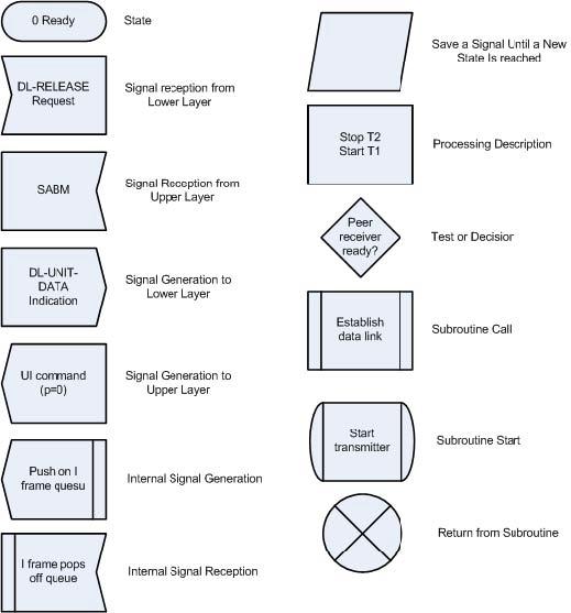
56 56
57 Appendix C2a - Simplex Physical Layer State Machines C2a.1 Interaction with the Link Multiplexer The Link Multiplexer State Machine directs the operation of the simplex Physical State Machine through the following physical (PH) primitives: PH-SEIZE Request. This primitive requests the simplex state machine to begin transmitting at the next available opportunity. When that opportunity has been identified (according to the CSMA/p-persistence algorithm included within), the transmitter started, a parameterized window provided for the startup of a conventional repeater (if required), and a parameterized time allowed for the synchronization of the remote station s receiver (known as TXDELAY in most implementations), then a PH-SEIZE Confirm primitive is returned to the link multiplexer. PH-DATA Request. This primitive from the Link Multiplexer State Machine provides an AX.25 frame of any type (UI, SABM, I, etc.) that is to be transmitted. An unlimited number of frames may be provided. If the transmission exceeds the 10 minute limit or the anti-hogging time limit, the half-duplex Physical State Machine automatically relinquishes the channel for use by the other stations. The transmission is automatically resumed at the next transmission opportunity indicated by the CSMA/p-persistence contention algorithm. PH-RELEASE Request. The Link Multiplexer State Machine provides this primitive when a submitted sequence of frames to be transmitted on behalf of a particular AX.25 connection has been completed. The simplex Physical State Machine will piggyback any straggling digipeat frames (if time permits) and then relinquish the channel. PH-EXPEDITED-DATA Request. This primitive from the Link Multiplexer State Machine provides the AX.25 frame that is to be transmitted immediately. The simplex Physical State Machine gives preference to priority frames over normal frames, and will take advantage of the PRIACK window. Priority frames can be provided by the link multiplexer at any time; a PH- SEIZE Request and subsequent PH Release Request are not employed for priority frames. PH-DATA Indication. During reception, the simplex Physical State Machine provides each AX.25 frame to the link multiplexer in a Frame primitive (Section C2a.2). No analysis is done on the frame by the simplex Physical State Machine; it does not examine lengths, the frame check sequence, the need for digipeating, or any other content of the frame; these responsibilities are carried out by the higher level state machines. PH-BUSY Indication. The simplex Physical State Machine provides this primitive whenever the channel becomes busy. Busy here means the detection of a valid modem synchronization sequence, HDLC Flags or HDLC frames not the detection of an FM carrier on a two-meter radio. An indication of busy is provided to the higher layer state machines so that various timers that supervise the AX.25 connection can be suspended. This avoids the undesirable situation on a busy channel where AX.25, having sent data and expecting and acknowledgement, times out and attempts retransmissions and the only reason an acknowledgement was not received was because the remote station did not yet have a chance to make a transmission. Since the channel is simplex, this primitive is also provided when the simplex Physical State Machine starts transmitting. PH-QUIET Indication. The simplex Physical State Machine provides this primitive whenever the channel becomes quiet. Since the channel is simplex, this primitive is also provided when the simplex Physical State Machine finishes transmitting. 57
58 C2a.2 Interface to the Hardware As the lowest layer state machine in the standard, the physical layer state machine is envisioned to manipulate a typical radio transceiver and modem. It employs a number of primitives, described below: HW-TON Request. This primitive keys the transceiver s PTT line. HW-TOFF Request. This primitive unkeys the transceiver s PTT line. HW-DATA Request. This primitive passes data for actual transmission of a frame from the physical layer to the hardware. Although SDL representation of bit-by-bit transmission of the contents of a frame is possible, it is not used here because the additional complexity was not required. The hardware is envisioned to utilize an integrated circuit (Z8530, I8274, I82530, etc.) to provide the conversion to/from a bit stream to bytes of data, handle bit-stuffing, etc. Frame - Differs from all other primitives used in the state machines in one respect: it is not atomic. Under this model, the Frame primitive occupies time; this allows the duplex Physical State Machine to consume time associated with transmission, and to trigger the ten minute transmitter protection and anti-hogging timers. HW-DATA Indication. This primitive passes data from actual reception of a frame from hardware to the physical layer. Although SDL representation of bit-by-bit transmission of the contents of a frame is possible, it is not used here because the additional complexity was not required. The hardware is envisioned to utilize an integrated circuit (Z8530, I8274, I82530, etc.) to provide the conversion to/from a bit stream to bytes of data, handle bit-stuffing, etc. Frame - Differs from all other primitives used in the state machines in one respect: it is not atomic. Under this model, the Frame primitive occupies time; this allows the duplex Physical State Machine to consume time associated with transmission, and to trigger the ten minute transmitter protection and antihogging timers. HW-AOS Indication. This primitive indicates the presence of modem synchronization, flag fill or frame structure. HW-LOS Indication. This primitive indicates the loss of modem synchronization, flag fill and frame structure. C2a.3 Internal Operation of the Machine All queues are first-in, first-out. These items are used in a straightforward manner; no further explanation is deemed necessary here. Note that the anti-hogging time limit is not applied to the digipeating function. However, the 10-minute transmitter timer is enforced while digipeating. In the unlikely event that the 10-minute limit is exceeded, the transmission of digipeated frames is temporarily suspended and the channel is relinquished. After other stations have had the opportunity to digipeat frames (i.e., PRIACK expires), but before the p- persistence algorithm takes effect, the state machine jumps back on the channel to resume transmission of those frames still in the priority queue. While this logic is provided in the state diagrams for completeness, it seems unlikely that it would ever be used. Below is a summary of primitives, states, queues, flags, errors, and timers used in the physical layer state machines: PH Primitives (Received from the Link Multiplexer): PH-SEIZE Request PH-RELEASE Request 58
59 PH-EXPEDITED-DATA Request PH-DATA Request PH Primitives (Sent to the Link Multiplexer): PH-SEIZE Confirm PH-BUSY Indication PH-QUIET Indication PH-DATA Indication PH Primitives (Received from the Radio): HW-AOS Indication HW-LOS Indication HW-DATA Indication PH Primitives (Sent to the Radio): HW-TON Request HW-TOFF Request HW-DATA Request States: 0 Ready 1 Receiving 2 Transmitter Suppression 3 Transmitter Start 4 Transmitting 5 Digipeating 6 Receiver Start Error Codes: No Error Codes Used. Queues: Priority Queue holds all expedited data frames to be transmitted in the order in which they arrived from the higher layer. Normal Queue holds all normal frames, plus Seize and Release Requests, in the order in which they arrived from the higher level. Flags and Parameters: Digipeating set when this transmission is for digipeating frames. Cleared when this transmission is for normal frames. Repeater Up set when repeater is expected to still be transmitting. Cleared when repeater carrier is expected to have dropped. Interrupted set when anti-hogging or 10-minute transmitter limits have interrupted the transmission of normal frames. p p-persistence value, in the range Timers: 59
60 T100 Repeater Hang (AXHANG) T101 Priority Window (PRIACK) T102 Slot Time (p-persistence) T103 Transmitter Startup (TXDELAY) T104 Repeater Startup (AXDELAY) T105 Remote Receiver Sync T106 Ten Minute Transmission Limit T107 Anti-Hogging Limit T108 Receiver Startup 60
61 Figure C2a.1 Simplex Physical Ready State. 61
62 Figure C2a.2 Simplex Physical Receiving State. 62
63 Figure C2a.3 Simplex Physical Transmitter Suppression State. 63
64 Figure C2a.4 Simplex Physical Transmitter Start State. 64
65 Figure C2a.5 Simplex Physical Transmitting State. 65
66 Figure C2a.6. Simplex Physical Digipeating State. 66
67 Figure C2a.7 Simplex Physical Receiver Start State. 67
68 Figure C2a.s Simplex Physical Subroutines. 68
69 Appendix C2b - Duplex Physical Layer State Machines C2b.1 Interaction with the Link Multiplexer The Link Multiplexer State Machine directs the operation of the duplex Physical State Machine through the physical (PH) primitives described below. PH-SEIZE Request. This primitive requests the duplex state machine to begin transmitting. When that opportunity has been identified, the transmitter is started and a parameterized time is allowed for the synchronization of the remote station s receiver (known as TXDELAY in most implementations), then a PH-SEIZE Confirm primitive is returned to the link multiplexer. PH-DATA Request. This primitive from the Link Multiplexer State Machine provides a AX.25 frame of any type (UI, SABM, I, etc.) that is to be transmitted. An unlimited number of frames may be provided. If the transmission exceeds the 10minute limit or the anti-hogging time limit, the duplex Physical State Machine shuts down the transmitter. PH-RELEASE Request. The Link Multiplexer State Machine provides this primitive when the submission of a sequence of frames to be transmitted on behalf of a particular AX.25 connection has been completed. PH-EXPEDITED-DATA Request. This primitive from the Link Multiplexer State Machine provides the AX.25 frame that is to be transmitted immediately. The duplex Physical State Machine gives preference to priority frames over normal frames. Priority frames can be provided by the link multiplexer at any time. PH-DATA Indication. During reception, the duplex Physical State Machine provides each AX.25 frame to the link multiplexer in a Frame primitive. No analysis is done on the frame by the duplex Physical State Machine; it does not examine lengths, the frame check sequence, or any other content of the frame; these responsibilities are carried out by the higher level state machines. PH-BUSY Indication. The duplex Physical State Machine provides this primitive whenever the channel becomes busy. Busy here means the detection of a valid modem synchronization sequence, HDLC Flags or HDLC frames not the detection of an FM carrier on a two-meter radio. An indication of busy is provided to the higher layer state machines so that various timers which are supervise the AX.25 connection can be suspended. This avoids the undesirable situation on a busy channel where AX.25, having sent data and expecting an acknowledgment, times out and attempts retransmissions and the only reason an acknowledgment was not received was because the remote station did not yet have a chance to make a transmission. PH-QUIET Indication. The duplex Physical State Machine provides this primitive whenever the channel becomes quiet. C2b.2 Interface to the Hardware As the lowest layer state machine in the standard, this machine manipulates a typical radio transceiver. The following primitives are used: HW-TON Request. This primitive keys the transceiver s PTT line. HW-TOFF Request. This primitive unkeys the transceiver s PTT line. HW-DATA Request. This primitive passes data for actual transmission of a frame from the physical layer to the hardware. Although SDL representation of bit-by-bit transmission of the contents of a frame is possible, it is not used here because the additional complexity was not required. The Frame primitive, however, differs from all other primitives used in the state 69
70 machines in one respect: it is not atomic. Under this model, the Frame primitive occupies time; this allows the duplex Physical State Machine to consume time associated with transmission, and to trigger the ten minute transmitter protection and anti-hogging timers. HW-DATA Indication. This primitive passes data from actual reception of a frame from hardware to the physical layer. HW-AOS Indicate. This primitive indicates the presence of modem synchronization, flag fill or frame structure. HW-LOS Indicate. This primitive indicates the loss of modem synchronization, flag fill or frame structure. C2b.3 Internal Operation of the Machine All queues are first-in, first-out. These items are used in a straightforward manner; no further explanation is deemed necessary here. Below is a summary of primitives, states, queues, flags, errors, and timers used in the physical layer state machines: PH Primitives (Received from the Link Multiplexer): PH-SEIZE Request PH-RELEASE Request PH-EXPEDITED-DATA Request PH-DATA Request PH Primitives (Sent to the Link Multiplexer): PH-SEIZE Confirm PH-BUSY Indication PH-QUIET Indication PH-DATA Indication PH Primitives (Received from the Radio): HW-AOS Indication HW-LOS Indication HW-DATA Indication PH Primitives (Sent to the Radio): HW-TON Request HW-TOFF Request HW-DATA Request States: 0 Receiver Ready 1 Receiving 2 Transmitter Ready 3 Transmitter Start 4 Transmitting 70
71 Error Codes: No Error Codes Used. Queues: Normal Queue holds all normal frames, plus Seize and Release Requests, in the order in that they arrived from the higher level. Flags and Parameters: Interrupted set when anti-hogging or 10-minute transmitter limits have interrupted the transmission of normal frames. Timers: T105 remote receiver sync T minute transmission limit T107 anti-hogging limit 71
72 Figure C2b.1 Duplex Physical Receiver Ready State. 72
73 Figure C2b.2 Duplex Physical Receiving State. 73
74 Figure C2b.3 Duplex Physical Transmitter Ready State. 74
75 Figure C2b.4 Duplex Physical Transmitter Start State. 75
76 Figure C2b.5 Duplex Physical Transmitting State. 76
77 Appendix C3 - Link Multiplexer State Machine C3.1 Interaction with the Data-Link State Machine The Data-link State Machine directs the operation of the Link Multiplexer State Machine through the link multiplexer (LM) primitives described below. LM-SEIZE Request. This primitive requests the Link Multiplexer State Machine to arrange for transmission at the next available opportunity. The Data-link State Machine uses this primitive when an acknowledgment must be made, but the exact frame in which the acknowledgment will be sent will be chosen when the actual time for transmission arrives. The Link Multiplexer State Machine uses the LMSEIZE Confirm primitive to indicate that the transmission opportunity has arrived. After the Data-link State Machine has provided the acknowledgment, the Data-link State Machine gives permission to stop transmission with the LM Release Request primitive. LM-DATA Request. This primitive from the Data-link State Machine provides an AX.25 frame of any type (UI, SABM, I, etc.) that is to be transmitted. An unlimited number of frames may be provided. The Link Multiplexer State Machine accumulates the frames in a first-in, first-out queue until it is time to transmit them. LM-DATA Indication. This primitive from the Link Multiplexer State Machine provides an AX.25 frame of any type (UI, SABM, I, etc.) that has been received. An unlimited number of frames may be provided. C3.2 Interaction with the Physical Layer State Machine The Link Multiplexer State Machine works with the physical layer state machine. It is important to note that variations in the operating characteristics of radio channels are kept hidden from the Link Multiplexer State Machine. The Link Multiplexer State Machine uses the same primitives to communicate with the physical layer state machine, regardless of the latter s type. PH-SEIZE Request. This primitive is used by the Link Multiplexer State Machine before each transmission to request access to the radio channel. PH-SEIZE Confirm. This primitive notifies the Link Multiplexer State Machine when access has been obtained (i.e., the transmitter is operating, any intervening repeater has had an opportunity to be activated, the remote station s receiver has had an opportunity to become synchronized, and the channel is considered ready to send traffic). PH-DATA Request. This primitive is used by the Link Multiplexer State Machine to deliver each frame to the physical layer state machine. PH-RELEASE Request. This primitive is used when all frames that have been awaiting transmission for a given link have been submitted for transmission. The intention here is that a single transmission will contain frames for only one remote station. The PH-RELEASE Request primitive permits the physical layer state machine to release the channel for use by others, for digipeating, and for receipt of acknowledgments in a contention environment (such as shared simplex channels). PH-DATA Indication. This primitive is used by the physical layer state machine to provide incoming frames to the Link Multiplexer State Machine. The Link Multiplexer State Machine checks each incoming frame for FCS errors. Correctly-received frames are checked to see if digipeating by the station has been requested and if the digipeat function is enabled (a user specified parameter); if so, the frame is resubmitted to the physical layer state machine in a 77
78 Digipeat Frame primitive. Correctly-received frames addressed to this station are delivered to the indicated higher-layer Data-link State Machine (see Section 5.3.1). PH-EXPEDITE-DATA Request. This primitive is used by the Link Multiplexer State Machine to submit a frame to the physical layer state machine to be transmitted immediately. (PH-SEIZE Request and PH-RELEASE Request are not used for digipeat operation.) PH-BUSY Indication. This primitive is used by the Link Multiplexer State Machine to suspend all AX.25 data-link timers. PH-QUIET Indication. This primitive is used by the Link Multiplexer State Machine to resume timing on all AX.25 data- link timers. The suspension of timers overcomes a problem noted in some implementations on busy channels. This problem occurs when frames are transmitted and a response is expected. If the channel is busy, it is possible for the retry timers (AX.25 timer T1) to expire before the remote station has had an opportunity to send any acknowledgment. This premature expiration causes needless retries and polling, which further clutters an already busy frequency. C3.3 Internal Operation of the Machine All queues are first-in, first-out. Three queues are used in conjunction with two flags to implement round-robin rotation among the various Data-link State Machines. The Awaiting Queue contains all primitives received from Data-link State Machines that have not yet had an opportunity to transmit. When a primitive pops off the Awaiting Queue, it and all other primitives from that same Data-link State Machine are placed in order on the Current Queue. The identity of this Data-link State Machine is maintained in the Current DL Flag. The Link Multiplexer State Machine then proceeds to obtain a transmission opportunity for that Data-link State Machine. Any further primitives received from that particular Data-link State Machine are added to the Current Queue. When the transmission opportunity arrives, everything in the Current Queue is conveyed to the physical layer state machine for transmission. (In the event of an overly large amount of information to be sent, the physical layer state machine makes whatever breaks in transmission are appropriate for reasonable channel sharing. This is done within the physical layer state machine and hidden from the higher layer.) Once everything has been sent for the current Data-link State Machine, its identity is moved to the Served List. Any subsequent primitives from this Data-link State Machine are added to the Served Queue. The Link Multiplexer State Machine then goes back to the Awaiting Queue to pop off the next primitive, and thereby identify which Data-link State Machine has the next transmission opportunity. If the Awaiting Queue is empty, then the Link Multiplexer State Machine concludes that all Data-link State Machines that had frames to be sent have now been served. The queue system is reset by converting the Served Queue into the new Awaiting Queue, and by purging all identifiers from the Served List. 78
79 Below is a summary of primitives, states, queues, flags, errors, and timers used in the link multiplexer state machines: LM Primitives (Received from LM): LM-SEIZE Request LM-RELEASE Request LM-DATA Request LM Primitives (Sent to LM): LM-SEIZE Confirm LM-DATA Indicate PH Primitives (Received from PH): PH-SEIZE Confirm PH-QUIET Indication PH-BUSY Indication PH-DATA Indication PH Primitives (Sent to PH): PH-SEIZE Request PH-RELEASE Request PH-EXPEDITED-DATA Request PH-DATA Request States: 0 Idle 1 Seize Pending 2 Seized Error Codes: No error codes used. Queues: Awaiting Queue queue of primitives received from Data-link State Machines that are not presently using the transmitter. Current Queue queue of primitives received from the Data-link State Machine that is presently using the transmitter. Served Queue queue of primitives received from Data-link State Machines that already have used the transmitter. Note: After all Data-link State Machines have had an opportunity to be served, then the Served Queue is converted to the Awaiting Queue. Variables: Current DL Identifies the Data-link State Machine currently using the transmitter. Served List Identifies the Data-link State Machines that have already used the transmitter. 79
80 This list is cleared when all Data-link State Machines with frames to send have been served. Timers: No timers used. 80
81 Figure C3.1 Link Multiplexer Idle State. 81
82 Figure C3.2 Link Multiplexer Seize Pending State. 82
83 Figure C3.3 Link Multiplexer Seized State. 83
84 Figure C3.4 Link Multiplexer Subroutines. 84
85 Appendix C4 - Data-Link State Machine C4.1 Interaction with the Data-Link Service Access Point The data link service access point directs the operation of the Data link State Machine through the data link (DL) primitives described below. The segmenter state machine is between the Data-link State Machine and the data link service access point. It passes all DL primitives except DL-DATA and DL- UNIT-DATA through transparently. DL-CONNECT Request. This primitive is used by the Layer 3 entity to request the establishment of an AX.25 connection. DL-CONNECT Indication. This primitive is used by the Data link State Machine to indicate an AX.25 connection has been requested. DL-CONNECT Confirm. This primitive is used by the Data link State Machine to indicate an AX.25 connection has been made. DL-DISCONNECT Request. This primitive is used by the Layer 3 entity to request the release of an AX.25 connection. DL-DISCONNECT Indication. This primitive is used by the Data link State Machine to indicate an AX.25 connection has been released. DL-DISCONNECT Confirm. This primitive is used by the Data link State Machine to indicate an AX.25 connection has been released and confirmed. DL-DATA Request. This primitive is used by the Layer 3 entity to request the transmission of data using connection oriented protocol. This frame is examined and acted upon by the segmenter, if necessary. DL-DATA Indication. This primitive is used by the reassembler to indicate reception of Layer 3 data using connection oriented protocol. DL-UNIT-DATA Request. This primitive is used by the Layer 3 entity to request the transmission of data using connectionless protocol. This frame is examined and acted upon by the segmenter, if necessary. DL-UNIT-DATA Indication. This primitive is used by the reassembler to indicate reception of Layer 3 data using connectionless protocol. DL-ERROR Indication. This primitive is used by the Data-link State Machine to indicate when frames have been received that are inconsistent with this protocol definition. This includes short frames, frames with inconsistent parameter values, etc. DL-FLOW-OFF request. This primitive is used by the Layer 3 entity to temporarily suspend the flow of incoming information. DL-FLOW-ON Request. This primitive is used by the Layer 3 entity to resume the flow of incoming information. C4.2 Interaction with the Link Multiplexer State Machine The Data link State Machine directs the operation of the Link Multiplexer State Machine through the data link (LM) primitives described below: LM-SEIZE Request. This primitive is used by the Data link State Machine to request the Link Multiplexer State Machine to arrange for transmission at the next available opportunity. The Data link State Machine uses this primitive when an acknowledgment must be made, but the exact frame in which the acknowledgment is sent will be chosen when the actual time for transmission 85
86 arrives. LM-SEIZE Confirm. This primitive indicates to the Data link State Machine that the transmission opportunity has arrived. LM-RELEASE Request. This primitive is used by the Link Multiplexer State Machine to stop transmission. LM-EXPEDITED-DATA Request. This primitive is used by the Data link State Machine to pass expedited data to the link multiplexer. LM-DATA Request. This primitive is used by the Data link State Machines to pass frames of any type (SABM, RR, UI, etc.) to the Link Multiplexer State Machine. LM-DATA Indication. This primitive is used by the Link Multiplexer State Machines to pass frames of any type (SABM, RR, UI, etc.) to the Data link State Machine. C4.3 Internal Operation of the Machine All queues are first-in, first-out. Below is a summary of primitives, states, queues, flags, errors, and timers used in the data link state machines: DL Primitives (Received from DL): DL-CONNECT Confirm DL-CONNECT Indicate DL-DISCONNECT Confirm DL-DISCONNECT Indicate DL-DATA Indicate DL-UNIT-DATA Indicate DL-ERROR Indicate DL Primitives (Sent to DL): DL-CONNECT Request DL-DISCONNECT Request DL-DATA Request DL-UNIT-DATA Request DL-FLOW-OFF Request DL-FLOW-ON Request LM Primitives (Sent to LM): LM-SEIZE Request LM-RELEASE Request LM-DATA Request LM-EXPEDITED-DATA Request LM Primitives (Received from LM): LM-SEIZE Confirm LM-DATA Indicate States: 0 Disconnected 86
87 1 Awaiting Connection 2 Awaiting Release 3 Connected 4 Timer Recovery Awaiting V2.2 Connection Error Codes: A F=1 received but P=1 not outstanding. B Unexpected DM with F=1 in states 3, 4 or 5. C Unexpected UA in states 3, 4 or 5. D UA received without F=1 when SABM or DISC was sent P=1. E DM received in states 3, 4 or 5. F Data link reset; i.e., SABM received in state 3, 4 or 5. I N2 timeouts: unacknowledged data. J N(r) sequence error. L Control field invalid or not implemented. M Information field was received in a U- or S-type frame. N Length of frame incorrect for frame type. O I frame exceeded maximum allowed length. P N(s) out of the window. Q UI response received, or UI command with P=1 received. R UI frame exceeded maximum allowed length. S I response received. T N2 timeouts: no response to enquiry. U N2 timeouts: extended peer busy condition. V No DL machines available to establish connection. Flags: Layer 3 Initiated SABM was sent by request of Layer 3; i.e., DL-CONNECT Request primitive. Peer Receiver Busy Remote station is busy and cannot receive I frames. Own Receiver Busy Layer 3 is busy and cannot receive I frames. Reject Exception A REJ frame has been sent to the remote station. Selective Reject Exception A SREJ frame has been sent to the remote station. Acknowledge Pending I frames have been successfully received but not yet acknowledged to the remote station. Variables: SRT Smoothed round trip time. T1V Next value for T1; default initial value is initial value of SRT. N1 Maximum number of octets in the information field of a frame, excluding inserted 0-bits. N2 Maximum number of retries permitted. Timers: T1 Outstanding I frame or P-bit. T3 Idle supervision (keep alive). 87
88 Queues: I Frame Queue queue of information to be transmitted in I frames. 88
89 Figure C4.1 Data Link Disconnected State. 89
90 Figure C4.2 Data Link Awaiting Connection State. 90
91 Figure C4.2 Data Link Awaiting Connection State. (Continued) 91
92 Figure C4.2 Data Link Awaiting Connection State. (Continued) 92
93 Figure C4.3 Data Link Awaiting Release State. 93
94 Figure C4.3 Data Link Awaiting Release State. (Continued) 94
95 Figure C4.4 Data Link Connected State. 95
96 Figure C4.4 Data Link Connected State. (Continued) 96
97 Figure C4.4 Data Link Connected State. (Continued) 97
98 Figure C4.4 Data Link Connected State. (Continued) 98
99 Figure C4.4 Data Link Connected State. (Continued) 99
100 Figure C4.5 Data Link Timer Recovery State. 100
101 Figure C4.5 Data Link Timer Recovery State. (Continued) 101
102 Figure C4.5 Data Link Timer Recovery State. (Continued) 102
103 Figure C4.5 Data Link Timer Recovery State. (Continued) 103
104 Figure C4.5 Data Link Timer Recovery State. (Continued) 104
105 Figure C4.5 Data Link Timer Recovery State. (Continued) 105
106 Figure C4.6 Data Link Awaiting V2.2 Connection State. 106
107 Figure C4.6 Data Link Awaiting V2.2 Connection State (Continued) 107
108 Figure C4.6 Data Link Awaiting V2.2 Connection State (Continued) 108
109 Figure C4.7 Data Link Subroutines. 109
110 Figure C4.7 Data Link Subroutines. (Continued) 110
111 Figure C4.7 Data Link Subroutines. (Continued) 111
112 Appendix C5 - Management Data Link State Machine C5.1 Interaction with the Data Link Service Access Point The Data-Link Service Access Point directs the operation of the Management Data link State Machine through the management data link (MDL) primitives described below: MDL-NEGOTIATE Request. This primitive is used by the Layer 3 entity to request the Data-link State Machine to notify/negotiate. MDL-NEGOTIATE Confirm. This primitive is used by the Management Data link State Machine to notify the Layer 3 entity notification/negotiation is complete. MDL-ERROR Indicate. This primitive is used by the Management Data link State Machine to notify the Layer 3 entity notification/negotiation has failed. C5.2 Interaction with the Link Multiplexer State Machine The Management Data link State Machine directs the operation of the Link Multiplexer State Machine through the link multiplexer (LM) primitives described below: LM-DATA Request. This primitive is used by the Data link State Machines to pass frames of any type (SABM, RR, UI, etc.) to the Link Multiplexer State Machine. LM-DATA Indication. This primitive is used by the Link Multiplexer State Machines to pass frames of any type (SABM, RR, UI, etc.) to the Data-link State Machine. C5.3 Internal Operation of the Machine The Management Data link State Machine handles the negotiation/notification of operational parameters. It uses a single command/response exchange to negotiate the final values of negotiable parameters. The station initiating the AX.25 connection will send an XID command after it receives the UA frame. If the other station is using a version of AX.25 earlier than 2.2, it will respond with an FRMR of the XID command and the default version 2.0 parameters will be used. If the other station is using version 2.2 or better, it will respond with an XID response. Below is a summary of primitives, states, queues, flags, errors, and timers used in the management data link state machines: MDL Primitives (Received from MDL): MDL-NEGOTIATE Confirm MDL-ERROR Indicate MDL-NEGOTIATE Request LM-DATA Request LM-DATA Indicate States: 0 Ready 1 Negotiating Error Codes: 112
113 A XID command without P=1. B Unexpected XID response. C Management retry limit exceeded. D XID response without F=1. Queues: None used. Variables: RC Retry count. NM201 Maximum number of retries of the XID command. MDL Primitives (Sent to MDL): LM Primitives (Sent to LM): LM Primitives (Received from LM): Timers: TM201 Retry timer for management functions. 113
114 Figure C5.1 Management Data Link Ready State. 114
115 Figure C5.2 Management Data Link Negotiating State. 115
116 Figure C5.3 MDL Classes of Procedures Negotiation Subroutines. 116
117 Figure C5.4 MDL Optional Functions Subroutines. 117
118 Figure C5.5 MDL N1 Negotiation Subroutines. 118
119 Figure C5.6 MDL Window Negotiation Subroutines. 119
120 Figure C5.7 MDL Retry Notification Subroutines 120
121 Figure C5.8 MDL T1 Negotiation Subroutines. 121
122 Appendix C6 - Segmenter/Reassembler C6.1 Segmenter State Machine Only the following DL primitives will be candidates for modification by the segmented state machine: DL-DATA Request. The user employs this primitive to provide information to be transmitted using connection-oriented procedures; i.e., using I frames. The segmenter state machine examines the quantity of data to be transmitted. If the quantity of data to be transmitted is less than or equal to the data link parameter N1, the segmenter state machine passes the primitive through transparently. If the quantity of data to be transmitted exceeds the data link parameter N1, the segmenter chops up the data into segments of length N1-2 octets. Each segment is prepended with a two octet header. (See Figures 3.1 and 3.2.) The segments are then turned over to the Data-link State Machine for transmission, using multiple DL Data Request primitives. All segments are turned over immediately; therefore the Data-link State Machine will transmit them consecutively on the data link. DL-UNIT-DATA Request. The user employs this primitive to provide information to be transmitted using connectionless procedures; i.e. using UI frames. The segmenter state machine examines the quantity of data to be transmitted. If the quantity of data to be transmitted is less than or equal to the data link parameter N1, the segmenter state machine passes the primitive through transparently. If the quantity of data to be transmitted exceeds the data link parameter N1, the segmenter chops up the data into segments of length N1-2 octets. Each segment is prepended with a two octet header. (See Figures 3.1 and 3.2.) The segments are then turned over to the Data-link State Machine for transmission, using multiple DL Data Request primitives. All segments are turned over immediately; therefore the Data-link State Machine will transmit them consecutively on the data link. All Other DL Primitives. All other DL primitives are passed through the segmenter state machine unchanged. C6.2 Reassembler State Machine All primitives from the Data-link State Machine are delivered transparently, except the following: DL-DATA Indication. This primitive is examined by the reassembler state machine. If the accompanying received data begins with an octet other than 0x08, it is assumed it has not been segmented, and is passed up transparently. If the data begins with 0x08, the reassembler state machine allocates buffers and switches to state 1. After various checks for errors, this segment and all remaining segments received in subsequent DL Data Indication primitives are assembled together to recreate the original larger data unit. If a segment is received without the proper PID or out of sequence, the accumulated packets are discarded, buffers are freed, a DL Error Indication is delivered and the state machine returns to state 0. The larger data unit is delivered with one DL Data Indication primitive. DL-UNIT-DATA Indication. This primitive is examined by the reassembler state machine. If the accompanying received data begins with an octet other than 0x08, it is assumed it has not been segmented, and is passed up transparently. If the data begins with 0x08, the reassembler state machine allocates buffers and switches to state 2. After various checks for errors, this segment and all remaining segments received in subsequent DL Unit Data Indication primitives are assembled together to recreate the original larger data unit. If a segment is received without the proper PID or out of sequence, the accumulated packets are discarded, buffers are freed, a DL Error Indication is delivered and the state machine returns to state 0. The larger data unit is 122
123 delivered with one DL Unit Data Indication primitive. Timer TR210 Expiry. This primitive occurs when a segment is not received before timer TR210 times out. When this primitive is received, the accumulated packets are discarded, buffers are freed and the state machine returns to state 0. A DL Error Indication is passed to the higher level. All Other DL Primitives. All other DL primitives are passed through the reassembler state machine unchanged. If the state machine is in states 1 or 2 when another DL primitive is received, the accumulated packets are discarded, buffers are freed and the state machine returns to state 0. A DL Error Indication is passed to the higher level. C6.3 Internal Operation of the Machine Below is a summary of primitives, states, queues, flags, errors, and timers used in the segmenter/reassembler link state machines: DL Primitives (Received from DLSAP} DL-DATA Request DL-UNIT-DATA Request NOTE: all other primitives are passed transparently. DL Primitives (Sent to DLSAP) DL-DATA Indication DL-UNIT-DATA Indication DL-ERROR Indication NOTE: all other primitives are passed transparently. DL Primitives (Received from the Data Link State Machine) DL-DATA Indication DL-UNIT-DATA Indication NOTE: all other primitives are passed transparently. DL Primitives (Sent to the Data Link State Machine) DL-DATA Request DL-UNIT-DATA Request NOTE: all other primitives are passed transparently. Segmenter States: 0 Null 1 Reassembling Data 2 Reassembling Unit Data Queues: None. Error Codes: Y data too long to segment Z reassembly error. 123
124 Variables: N number of segments remaining to be reassembled. Timers: TR210 time limit for receipt of next segment. C6.3.1 Internal Operation of the Segmenter State Machine The segmenter state machine operation is quite straightforward. Only one state exists for this machine. C6.3.2 Internal Operation of the Reassembler State Machine The reassembler state machine resides in the Null state until the start of a segmented data stream is detected. At this point, a check is made to ensure that the first segment received is, in fact, the first segment of the message. This check is performed by examining octet 2, bit 8 of the segment header (see Figure 6.X). If this is not the first segment, then the reassembler state machine assumes that the actual first segment was lost somewhere, and signals an error. All segments will be discarded as they are received. Assume now that the first segment was received correctly. The reassembler state machine then allocates sufficient storage to receive all the remaining segments; this prevents deadly embrace (resource deadlock) conditions. The reassembler state machine enters either the reassembling data state (if segments are arriving in I frames) or the reassembling unit data state (if segments are arriving in UI frames). A lengthy timer supervises both of these states; its purpose is to protect the reassembly process from hanging if a very long delay happens to occur (e.g., the remote station breaks down and never completes transmission). This timer is TR210: R for reassembler; 2 for level 2, the data link level of the OSI interconnect model; and 10 simply to avoid confusion with any other timers in this family of state machines. Each incoming segment is examined to ensure that it is indeed the next expected segment. If the loss of a segment is detected, the entire accumulation of data is discarded and an error notification is provide to the AX.25 user. No attempt is made by the segmenter and reassembler state machines to recover segmented data units; this is left to the higher level AX.25 user. Rather, the reassembler state machine works to ensure that large data units are completely received and correctly reassembled over the data link. In other words, segmentation error detection is provided, but no segmentation error correction is provided. The reassembler state machine also insists that, once the transmission of a segmented large data unit is begun, all segments will be transmitted until the complete large data unit has been transferred. No other event is permitted to occur over the data link. This constraint is imposed for two reasons: To ensure that stations with multiple data links minimize the amount of buffer capacity tied up in partially received or transmitted large data units (which in turn reduces connectionless links); and To minimize the delay in transmission of large data units, once the large data unit has reached the top of the queue. C6.4 Final Observations As mentioned above, the use of connection-oriented data link procedures is recommended when segmentation is anticipated on data links with even moderately low collision levels. If connectionless data link procedures (UI frames) are used to carry segments, the loss of a single UI frame will result in the loss of the entire segmented large data unit; higher level attempts at recovery will significantly 124
125 increase congestion on the physical channel. 125
126 Figure C-6.1 Segmenter Ready State. 126
127 Figure C-6.2 Reassembler Ready State. 127
128 Figure C-6.3 Reassembler Assembling Data State. 128
129 Figure C-6.4 Reassembler Assembling Unit Data State. 129
130 Appendix D - Data Link Service Access Point and Primitives D.1 Model of a Data-Link Connection A Data Link Service Access Point (DLSAP) is the point at which the data-link layer provides services to Layer 3. It provides a uniform programming interface to access the data-link services. This Appendix specifies this interface but does not specify the upper layer entities. In a basic user TNC, the upper layer entity may consist only of a Layer 7 user application with Layers 3-6 being null. The following primitives are used to pass commands and receive responses from the DLSAP: DL-CONNECT Request. (Called Call sign). This primitive is used by the Layer 3 entity to request the establishment of an AX.25 connection. DL-CONNECT Indication. (Calling Call sign). This primitive is used by the Data-link State Machine to indicate an AX.25 connection has been requested. DL-CONNECT Confirm. (VOID). This primitive is used by the Data-link State Machine to indicate an AX.25 connection has been made. DL-DISCONNECT Request. This primitive is used by the Layer 3 entity to request the release of an AX.25 connection. DL-DISCONNECT Indication. This primitive is used by the Data-link State Machine to indicate an AX.25 connection has been released. DL-DISCONNECT Confirm. This primitive is used by the Data-link State Machine to indicate an AX.25 connection has been released and confirmed. DL-DATA Request. This primitive is used by the Layer 3 entity to request the transmission of data using connection-oriented protocol. This frame is examined and acted upon by the segmenter, if necessary. DL-DATA Indication. This primitive is used by the reassembler to indicate reception of Layer 3 data using connection-oriented protocol. DL-UNIT-DATA Request. This primitive is used by the Layer 3 entity to request the transmission of data using connectionless protocol. This frame is examined and acted upon by the segmenter, if necessary. DL-UNIT-DATA Indication. This primitive is used by the reassembler to indicate reception of Layer 3 data using connectionless protocol. DL-ERROR Indication. This primitive is used by the Data-link State Machine to indicate when frames have been received that are inconsistent with this protocol definition. This includes short frames, frames with inconsistent parameter values, etc. The error indications are discussed in the SDL appendices. DL-FLOW-OFF Request. This primitive is used by the Layer 3 entity to temporarily suspend the flow of incoming information. DL-FLOW-ON Request. This primitive is used by the Layer 3 entity to resume the flow of incoming information. MDL-NEGOTIATE Request. This primitive is used by the Layer 3 entity to request the Data-link State Machine to notify/negotiate. MDL-NEGOTIATE Confirm. This primitive is used by the Management Data-link State Machine to notify the Layer 3 entity that notification/negotiation is complete. MDL-ERROR Indicate. This primitive is used by the Management Data-link State Machine to notify the Layer 3 entity that notification/negotiation has failed. 130
131 D.2 Queue Model Concepts The queue model represents the operation of the Data-Link Connection (DLC) in the abstract by a pair of queues linking the two DLSAPs. There is one queue for each direction of information flow (see Figure D.1). DLSAP The pair of queues is considered to be available for each Data-Link Service (DLS) user. Each queue represents a DLS flow control function in one direction of transfer. The ability of a user to add objects to a queue will be determined by the behavior of the other DLS user in removing objects from the queue and by the state of the queue. Objects are entered or removed from the queue as a result of interactions at the two DLSAPs. The following objects may be placed in a queue by a DLS user: A connect object, representing a DL-CONNECT primitive and its parameters. A data object, representing a DL-DATA primitive and its parameters. A disconnect object, representing a DL-DISCONNECT primitive and its parameters. The following object may be placed in a queue by the DLS provider: A disconnect object, representing a DL-DISCONNECT primitive and its parameters. The queues are defined to have the following general properties: A queue is empty before a connect object has been entered and can be returned to this state, with loss of its contents, by the DLS provider. Objects are entered into a queue by the sending DLS user, subject to control by the DLS provider. Objects may also be entered by the DLS provider. Objects are removed from the queue, under the control of the receiving DLS user. Objects are normally removed in the same order that they were entered. A queue has a limited capacity, but this capacity is not necessarily either fixed or determinable. D.3 DLC Establishment A pair of queues is associated with a DLC between two DLSAPs when the DLS provider receives a DLCONNECT request primitive at one of the DLSAPs, and a connect object is entered into one of the queues. From the standpoint of the DLS users of the DLC, the queues remain associated with the DLC until a disconnect object representing a DL-DISCONNECT primitive is either entered or removed from the queue. DLS user A, who initiates a DLC establishment by entering a connect object representing a DL- CONNECT request primitive into the queue from DLS user A to DLS user B, is not allowed to enter any other object, other than a disconnect object, into the queue until after the connect object representing the DL-CONNECT confirm primitive has been removed from the DLS user B to DLS user A queue. In the queue from DLS user B to DLS user A, objects can be entered only after DLS user B has entered a connect object representing a DL-CONNECT response primitive. 131

132 The properties exhibited by the queues while the DLC exists represent the agreements reached among the DLS users and the DLS provider during this connection establishment procedure. D.4. Data Transfer Flow control on the DLC is represented in this queue model by the management of the queue capacity, allowing objects to be added to the queues. The addition of an object may prevent the addition of a further object. Once objects are in the queue, the DLS provider may manipulate pairs of adjacent objects, resulting in deletion. An object may be deleted if, and only if, the object that follows it is defined to be destructive with respect to the object. If necessary, the last object on the queue will be deleted to allow a destructive object to be entered; thus, a destructive object may always be added to the queue. Disconnect objects are defined to be destructive with respect to all objects. The relationship between objects that may be manipulated in the above fashion are summarized in Figure D.1. Figure D.1 Relationships between Queue Model Objects. Whether the DLS provider performs actions resulting in deletion or not will depend upon the behavior of the DLC users. In general, if a DLS user does not remove objects from a queue, the DLS provider shall, after some unspecified period of time, perform all the permitted deletions. D.5 DLC Release The insertion into a queue of a disconnect object, which may occur at any time, represents the initiation of the DLC release procedure. The release procedure may be destructive with respect to other objects in the two queues and eventually results in the emptying of the queues and the dissociation of the queues with the DLC. The insertion of a disconnect object may also represent the rejection of a DLC establishment attempt or the failure to complete DLC establishment. In such cases, if a connect object representing a DL- 132
INTERNATIONAL TELECOMMUNICATION UNION. SERIES Q: DIGITAL SUBSCRIBER SIGNALLING SYSTEM No. 1 (DSS 1), DATA LINK LAYER
, DATA LINK LAYER") INTERNATIONAL TELECOMMUNICATION UNION CCITT Q.921 THE INTERNATIONAL TELEGRAPH AND TELEPHONE CONSULTATIVE COMMITTEE (11/1988) SERIES Q: DIGITAL SUBSCRIBER SIGNALLING SYSTEM No. 1 (DSS 1), DATA LINK LAYER
INTERNATIONAL TELECOMMUNICATION UNION CCITT Q.921 THE INTERNATIONAL TELEGRAPH AND TELEPHONE CONSULTATIVE COMMITTEE (11/1988) SERIES Q: DIGITAL SUBSCRIBER SIGNALLING SYSTEM No. 1 (DSS 1), DATA LINK LAYER
INTERNATIONAL TELECOMMUNICATION UNION. SERIES X: DATA COMMUNICATION NETWORKS: SERVICES AND FACILITIES, INTERFACES Interfaces
 INTERNATIONAL TELECOMMUNICATION UNION CCITT X.25 THE INTERNATIONAL TELEGRAPH AND TELEPHONE CONSULTATIVE COMMITTEE (11/1988) SERIES X: DATA COMMUNICATION NETWORKS: SERVICES AND FACILITIES, INTERFACES Interfaces
(Sicherungsschicht) Chapter 5 (part 2) [Wa0001] HDLC - 1.
![(Sicherungsschicht) Chapter 5 (part 2) [Wa0001] HDLC - 1.](/thumbs/74/71111055.jpg "(Sicherungsschicht) Chapter 5 (part 2) [Wa0001] HDLC - 1.") Data Link Layer (cont.) (Sicherungsschicht) Chapter 5 (part 2) [Wa0001] HDLC - 1 LOGICAL LINK CONTROL MEDIUM ACCESS CONTROL PHYSICAL SIGNALING DATA LINK LAYER PHYSICAL LAYER ACCESS UNIT INTERFACE PHYSICAL
Data Link Layer (cont.) (Sicherungsschicht) Chapter 5 (part 2) [Wa0001] HDLC - 1 LOGICAL LINK CONTROL MEDIUM ACCESS CONTROL PHYSICAL SIGNALING DATA LINK LAYER PHYSICAL LAYER ACCESS UNIT INTERFACE PHYSICAL
Data Link Control Protocols
 Data Link Control Protocols need layer of logic above Physical to manage exchange of data over a link frame synchronization flow control error control addressing control and data link management Flow Control
Data Link Layer (cont.) ( h h h ) (Sicherungsschicht) HDLC - 1.
 ( h h h ) (Sicherungsschicht) HDLC - 1.") Data Link Layer (cont.) ( h h h ) (Sicherungsschicht) HDLC - 1 LOGICAL L LINK CONTROL MEDIUM ACCESS CONTROL PHYSICAL SIGNALING DATA LINK LAYER PHYSICAL LAYER ACCESS UNIT INTERFACE PHYSICAL MEDIA ATTACHMENT
Data Link Layer (cont.) ( h h h ) (Sicherungsschicht) HDLC - 1 LOGICAL L LINK CONTROL MEDIUM ACCESS CONTROL PHYSICAL SIGNALING DATA LINK LAYER PHYSICAL LAYER ACCESS UNIT INTERFACE PHYSICAL MEDIA ATTACHMENT
Data Link Control. Claude Rigault ENST Claude Rigault, ENST 11/3/2002. Data Link control 1
 Data Link Control Claude Rigault ENST claude.rigault@enst.fr Data Link control Data Link Control Outline General principles of Data Link Control HDLC Data Link control 2 General principles of Data Link
Flow control: Ensuring the source sending frames does not overflow the receiver
 Layer 2 Technologies Layer 2: final level of encapsulation of data before transmission over a physical link responsible for reliable transfer of frames between hosts, hop by hop, i.e. on a per link basis
INTERNATIONAL TELECOMMUNICATION UNION. SERIES X: DATA NETWORKS AND OPEN SYSTEM COMMUNICATION Public data networks Interfaces
 INTERNATIONAL TELECOMMUNICATION UNION ITU-T X.25 TELECOMMUNICATION STANDARDIZATION SECTOR OF ITU (10/96) SERIES X: DATA NETWORKS AND OPEN SYSTEM COMMUNICATION Public data networks Interfaces Interface
Chapter 7: Data Link Control. Data Link Control Protocols
 Chapter 7: Data Link Control CS420/520 Axel Krings Page 1 Data Link Control Protocols Need layer of logic above Physical to manage exchange of data over a link frame synchronization flow control error
Chapter 7: Data Link Control. CS420/520 Axel Krings Page 1
 Chapter 7: Data Link Control CS420/520 Axel Krings Page 1 Data Link Control Protocols Need layer of logic above Physical to manage exchange of data over a link frame synchronization flow control error
HDLC PROTOCOL. Michel GARDIE
 HDLC PROTOCOL Michel GARDIE INT/LOR/RIP October 15, 2007 The version of this document is temporary. There are still several mistakes. I'm sorry for that. email: michel.gardie@int-edu.eu 1985 FRANCE TELECOM
INTERNET ARCHITECTURE & PROTOCOLS
 INTERNET ARCHITECTURE & PROTOCOLS Set # 02 Delivered By: Engr Tahir Niazi Need for Data Link Layer possibility of transmission errors receiver need to regulate the rate at which data arrive that's why
3. Data Link Layer 3-2
 3. Data Link Layer 3.1 Transmission Errors 3.2 Error Detecting and Error Correcting Codes 3.3 Bit Stuffing 3.4 Acknowledgments and Sequence Numbers 3.5 Flow Control 3.6 Examples: HDLC, PPP 3. Data Link
Advanced Computer Networks. Rab Nawaz Jadoon DCS. Assistant Professor COMSATS University, Lahore Pakistan. Department of Computer Science
 Advanced Computer Networks Rab Nawaz Jadoon Department of Computer Science DCS COMSATS Institute of Information Technology Assistant Professor COMSATS University, Lahore Pakistan Advanced Computer Networks
Data and Computer Communications
 Data and Computer Communications Chapter 7 Data Link Control Protocols Eighth Edition by William Stallings Lecture slides by Lawrie Brown Data Link Control Protocols "Great and enlightened one," said Ten-teh,
Data link layer functions. 2 Computer Networks Data Communications. Framing (1) Framing (2) Parity Checking (1) Error Detection
 Framing (2) Parity Checking (1) Error Detection") 2 Computer Networks Data Communications Part 6 Data Link Control Data link layer functions Framing Needed to synchronise TX and RX Account for all bits sent Error control Detect and correct errors Flow
2 Computer Networks Data Communications Part 6 Data Link Control Data link layer functions Framing Needed to synchronise TX and RX Account for all bits sent Error control Detect and correct errors Flow
HDLC (High level Data Link Control)
") High-level Data Link Control HDLC (High level Data Link Control) Modem, EIA-232, HDLC Framing and Procedures Agenda Line Management, Modems Introduction HDLC Station Types, Modes of Operation Frame Format,
High-level Data Link Control HDLC (High level Data Link Control) Modem, EIA-232, HDLC Framing and Procedures Agenda Line Management, Modems Introduction HDLC Station Types, Modes of Operation Frame Format,
Line Protocol Basics. HDLC (High level Data Link Control) Agenda. Additional Issues
 Agenda. Additional Issues") Line Protocol Basics High-level Data Link Control HDLC (High level Data Link Control), EIA-232, HDLC Framing and Procedures line protocol basics already explained serial transmission techniques bit-synchronization
Line Protocol Basics High-level Data Link Control HDLC (High level Data Link Control), EIA-232, HDLC Framing and Procedures line protocol basics already explained serial transmission techniques bit-synchronization
Chapter 3. The Data Link Layer. Wesam A. Hatamleh
 Chapter 3 The Data Link Layer The Data Link Layer Data Link Layer Design Issues Error Detection and Correction Elementary Data Link Protocols Sliding Window Protocols Example Data Link Protocols The Data
3GPP TS V7.2.0 ( )
") TS 25.462 V7.2.0 (2007-03) Technical Specification 3rd Generation Partnership Project; Technical Specification Group Radio Access Network; UTRAN Iuant interface: Signalling transport (Release 7) The present
TS 25.462 V7.2.0 (2007-03) Technical Specification 3rd Generation Partnership Project; Technical Specification Group Radio Access Network; UTRAN Iuant interface: Signalling transport (Release 7) The present
William Stallings Data and Computer Communications. Chapter 7 Data Link Control
 William Stallings Data and Computer Communications Chapter 7 Data Link Control Flow Control Ensuring the sending entity does not overwhelm the receiving entity Preventing buffer overflow Transmission time
AX.25 Data Link State Machine
 AX.25 Data Link State Machine Eric L. Scace K3NA 10701 Five Forks Road Frederick MD 21701 USA 0. Summary This paper is part of a series of papers which provide extended ftite state machine representations
HDLC. King of the Link 2005/03/11. (C) Herbert Haas
 Herbert Haas") HDLC King of the Link (C) Herbert Haas 2005/03/11 What is HDLC? High-Level Data Link Control Early link layer protocol Based on SDLC (Synchronous-DLC, IBM) Access control on half-duplex modem-lines Connectionoriented
HDLC King of the Link (C) Herbert Haas 2005/03/11 What is HDLC? High-Level Data Link Control Early link layer protocol Based on SDLC (Synchronous-DLC, IBM) Access control on half-duplex modem-lines Connectionoriented
 ET3110 Networking and Communications UNIT 2: Communication Techniques and Data Link Control Protocol skong@itt-tech.edutech.edu Learning Objectives Identify methods of detecting errors. Use Hamming code
3GPP TS V ( )
") TS 25.462 V10.1.0 (2011-06) Technical Specification 3rd Generation Partnership Project; Technical Specification Group Radio Access Network; UTRAN Iuant interface: Signalling transport (Release 10) The
TS 25.462 V10.1.0 (2011-06) Technical Specification 3rd Generation Partnership Project; Technical Specification Group Radio Access Network; UTRAN Iuant interface: Signalling transport (Release 10) The
The University of Sydney AUSTRALIA. Advanced Communication Networks
 The University of Sydney AUSTRALIA School of Electrical and Information Engineering Advanced Communication Networks Chapter 5 ISDN Data Link Layer Based on chapter 8 of Stallings ISDN-4e book Abbas Jamalipour
##)44 6 BIS $!4! #/-02%33)/. 02/#%$52%3 &/2 $!4! #)2#5)4 4%2-).!4).' %15)0-%.4 $#% 53).' %22/2 #/22%#4)/. 02/#%$52%3
44 6 BIS $!4! #/-02%33)/. 02/#%$52%3 &/2 $!4! #)2#5)4 4%2-).!4).' %15)0-%.4 $#% 53).' %22/2 #/22%#4)/. 02/#%$52%3") INTERNATIONAL TELECOMMUNICATION UNION ##)44 6 BIS THE INTERNATIONAL TELEGRAPH AND TELEPHONE CONSULTATIVE COMMITTEE $!4! #/--5.)#!4)/. /6%2 4(% 4%,%0(/.%.%47/2+ $!4! #/-02%33)/. 02/#%$52%3 &/2 $!4! #)2#5)4
INTERNATIONAL TELECOMMUNICATION UNION ##)44 6 BIS THE INTERNATIONAL TELEGRAPH AND TELEPHONE CONSULTATIVE COMMITTEE $!4! #/--5.)#!4)/. /6%2 4(% 4%,%0(/.%.%47/2+ $!4! #/-02%33)/. 02/#%$52%3 &/2 $!4! #)2#5)4
INTERNATIONAL TELECOMMUNICATION UNION DATA COMMUNICATION OVER THE TELEPHONE NETWORK
 INTERNATIONAL TELECOMMUNICATION UNION CCITT V.20 THE INTERNATIONAL (09/92) TELEGRAPH AND TELEPHONE CONSULTATIVE COMMITTEE DATA COMMUNICATION OVER THE TELEPHONE NETWORK SUPPORT BY AN ISDN OF DATA TERMINAL
Network Working Group Request for Comments: 1663 Category: Standards Track July 1994
 Network Working Group D. Rand Request for Comments: 1663 Novell Category: Standards Track July 1994 Status of this Memo PPP Reliable Transmission This document specifies an Internet standards track protocol
Data Link Layer. Learning Objectives. Position of the data-link layer. MCA 207, Data Communication & Networking
 Data Link Layer Bharati Vidyapeeth s Institute of Computer Applications and Management,New Delhi-63 by Vishal Jain U2. 1 Learning Objectives To introduce the design issues of data link layer. To discuss
ET4254 Communications and Networking 1
 Topic 9 Internet Protocols Aims:- basic protocol functions internetworking principles connectionless internetworking IP IPv6 IPSec 1 Protocol Functions have a small set of functions that form basis of
Appendix. Pioneering Protocols
 Appendix Pioneering Protocols STUDENTS STUDYING ancient civilizations and languages often wonder what is the point in studying cultures that no longer exist. How will the way people lived hundreds and
EUROPEAN ETS TELECOMMUNICATION September 1991 STANDARD
 EUROPEAN ETS 300 125 TELECOMMUNICATION September 1991 STANDARD Source: ETSI TC-SPS Reference: T/S 46-20 [CC] ICS: 33.080 Key words: ISDN, data link layer, Q.920, Q.921 Integrated Services Digital Network
AX.25 Link Multiplexor State Machine
 AX.25 Link Multiplexor State Machine Eric L. Scace K3NA 10701 Five Forks Road Frederick MD 21701 USA 0. Summary This paper is part of a series of papers which provide extended finite state machine representations
Chapter 3. The Data Link Layer
 Chapter 3 The Data Link Layer 1 Data Link Layer Algorithms for achieving reliable, efficient communication between two adjacent machines. Adjacent means two machines are physically connected by a communication
Chapter 11 Data Link Control 11.1
 Chapter 11 Data Link Control 11.1 Copyright The McGraw-Hill Companies, Inc. Permission required for reproduction or display. 11-1 FRAMING The data link layer needs to pack bits into frames, so that each
CCNA Exploration1 Chapter 7: OSI Data Link Layer
 CCNA Exploration1 Chapter 7: OSI Data Link Layer LOCAL CISCO ACADEMY ELSYS TU INSTRUCTOR: STELA STEFANOVA 1 Explain the role of Data Link layer protocols in data transmission; Objectives Describe how the
ETSI TS V7.1.0 ( )
") TS 100 946 V7.1.0 (2000-01) Technical Specification Digital cellular telecommunications system (Phase 2+); Radio Link Protocol (RLP) for data and telematic services on the Mobile Station - Base Station
TS 100 946 V7.1.0 (2000-01) Technical Specification Digital cellular telecommunications system (Phase 2+); Radio Link Protocol (RLP) for data and telematic services on the Mobile Station - Base Station
ETSI TC SMG TDoc SMG 938/97
 ETSI TC SMG TDoc SMG 938/97 Madrid, Spain Agenda item 5.1, GPRS 15-19 December, 1997 Source: Rapporteur GSM 04.64 Topic: GPRS Title: Change Requests to GSM 04.64 Date: 8 December, 1997 Introduction GSM
This Lecture. BUS Computer Facilities Network Management. Line Discipline. Data Link Layer
 This Lecture US35 - Computer Facilities Network Management Synchronisation and interfacing insufficient by themselves. Need to provide: Flow control - allow the receiver to regulate the flow of data. Error
Network Working Group Request for Comments: 1434 IBM March Data Link Switching: Switch-to-Switch Protocol
 Network Working Group Request for Comments: 1434 R. Dixon D. Kushi IBM March 1993 Status of this Memo Data Link Switching: Switch-to-Switch Protocol This memo provides information for the Internet community.
3GPP TS V8.0.0 ( )
") TS 24.022 V8.0.0 (2008-12) Technical Specification 3rd Generation Partnership Project; Technical Specification Group Core Network; Radio Link Protocol (RLP) for circuit switched bearer and teleservices
TS 24.022 V8.0.0 (2008-12) Technical Specification 3rd Generation Partnership Project; Technical Specification Group Core Network; Radio Link Protocol (RLP) for circuit switched bearer and teleservices
Network Working Group. Category: Informational DayDreamer August 1996
 Network Working Group Request for Comments: 1974 Category: Informational R. Friend Stac Electronics W. Simpson DayDreamer August 1996 PPP Stac LZS Compression Protocol Status of this Memo This memo provides
10.1 SERIAL PORTS AND UARTS
 RS- serial ports have nine circuits, which can be used for transferring data and signalling. can emulate the serial cable line settings and status of an RS- serial port. provides multiple concurrent connections
ETSI TS V ( ) Technical Specification
 Technical Specification") TS 125 462 V10.0.1 (2011-04) Technical Specification Universal Mobile Telecommunications System (UMTS); UTRAN Iuant interface: Signalling transport (3GPP TS 25.462 version 10.0.1 Release 10) 1 TS 125 462
TS 125 462 V10.0.1 (2011-04) Technical Specification Universal Mobile Telecommunications System (UMTS); UTRAN Iuant interface: Signalling transport (3GPP TS 25.462 version 10.0.1 Release 10) 1 TS 125 462
Chapter 11 Data Link Control 11.1
 Chapter 11 Data Link Control 11.1 Copyright The McGraw-Hill Companies, Inc. Permission required for reproduction or display. 11-1 1 FRAMING The data link layer needs to pack bits into frames,, so that
ISO/IEC INTERNATIONAL STANDARD
 INTERNATIONAL STANDARD ISO/IEC 13239 Second edition 2000-03-01 Information technology Telecommunications and information exchange between systems High-level data link control (HDLC) procedures Technologies
April Data Link Switching: Switch-to-Switch Protocol AIW DLSw RIG: DLSw Closed Pages, DLSw Standard Version 1.0
 Network Working Group Request for Comments: 1795 Obsoletes: 1434 Category: Informational L. Wells, Chair Internetwork Technology Institute A. Bartky, Editor Sync Research, Inc. April 1995 Data Link Switching:
Vodafone Digital Subscriber Signalling System No. 1 DSS1 Layer 2: LAPD
 nterface Specification Vodafone Digital Subscriber Signalling System No. 1 DSS1 Layer 2: LAPD nterface Specification Version: 2.1 28.07.2016 Vodafone DSS1 Layer 2 TU-T-L nterface Specification Date:28.07.2016
Superseded by a more recent version INTERNATIONAL TELECOMMUNICATION UNION
 INTERNATIONAL TELECOMMUNICATION UNION ITU-T X.36 TELECOMMUNICATION (04/95) STANDARDIZATION SECTOR OF ITU DATA NETWORKS AND OPEN SYSTEM COMMUNICATIONS PUBLIC DATA NETWORKS INTERFACES INTERFACE BETWEEN DATA
Institute of Computer Technology - Vienna University of Technology. L02 - Protocol Principles
 Protocol Principles Layering, CL versus CO Service, ARQ Techniques, Sequence umbers, Windowing, Flow Control Agenda Introduction 3 Layer Model and Service Types ARQ Techniques Introduction Idle RQ Continuous
ETSI TS V4.1.0 ( )
") TS 124 022 V4.1.0 (2003-06) Technical Specification Digital cellular telecommunications system (Phase 2+); Universal Mobile Telecommunications System (UMTS); Radio Link Protocol (RLP) for circuit switched
TS 124 022 V4.1.0 (2003-06) Technical Specification Digital cellular telecommunications system (Phase 2+); Universal Mobile Telecommunications System (UMTS); Radio Link Protocol (RLP) for circuit switched
Chapter 2 - Part 1. The TCP/IP Protocol: The Language of the Internet
 Chapter 2 - Part 1 The TCP/IP Protocol: The Language of the Internet Protocols A protocol is a language or set of rules that two or more computers use to communicate 2 Protocol Analogy: Phone Call Parties
Internetwork Protocols
 Internetwork Protocols Background to IP IP, and related protocols Internetworking Terms (1) Communications Network Facility that provides data transfer service An internet Collection of communications
Concept Questions Demonstrate your knowledge of these concepts by answering the following questions in the space that is provided.
 223 Chapter 19 Inter mediate TCP The Transmission Control Protocol/Internet Protocol (TCP/IP) suite of protocols was developed as part of the research that the Defense Advanced Research Projects Agency
TYPES OF ERRORS. Data can be corrupted during transmission. Some applications require that errors be detected and corrected.
 Data can be corrupted during transmission. Some applications require that errors be detected and corrected. TYPES OF ERRORS There are two types of errors, 1. Single Bit Error The term single-bit error
Narrowband ISDN. (ISDN = Integrated Services Digital Network)
") Narrowband ISDN (ISDN = Integrated Services Digital Network) critically: Invention Subscribers Don t Need (technology push instead of demand pull) is that really so? N-ISDN vs. B-ISDN (based on ATM) How
Narrowband ISDN (ISDN = Integrated Services Digital Network) critically: Invention Subscribers Don t Need (technology push instead of demand pull) is that really so? N-ISDN vs. B-ISDN (based on ATM) How
Ethereal Exercise 2 (Part A): Link Control Protocol
: Link Control Protocol") Course: Semester: ELE437 Ethereal Exercise 2 (Part A): Link Control Protocol Introduction In this exercise some details at the data link layer will be examined. In particular, the Link Control Protocol
Course: Semester: ELE437 Ethereal Exercise 2 (Part A): Link Control Protocol Introduction In this exercise some details at the data link layer will be examined. In particular, the Link Control Protocol
EUROPEAN ETS TELECOMMUNICATION August 1996 STANDARD
 EUROPEAN ETS 300 402-3 TELECOMMUNICATION August 1996 STANDARD Source: ETSI TC-SPS Reference: DE/SPS-05030-1 ICS: 33.080, 35.100.20 Key words: ISDN, DSS1, layer 2, D-channel, LAPF Integrated Services Digital
Networks: Access Management
 Networks: Access Management Class Notes # 3 Protocols and Layers (part 1) September 19, 2003 Functions A small set of functions form the basis of all protocols. Not all protocols have all functions; this
Internetworking Models The OSI Reference Model
 Internetworking Models When networks first came into being, computers could typically communicate only with computers from the same manufacturer. In the late 1970s, the Open Systems Interconnection (OSI)
Data and Computer Communications. Chapter 2 Protocol Architecture, TCP/IP, and Internet-Based Applications
 Data and Computer Communications Chapter 2 Protocol Architecture, TCP/IP, and Internet-Based s 1 Need For Protocol Architecture data exchange can involve complex procedures better if task broken into subtasks
POS SDLC EXPLAINED WHAT IS SDLC? SDLC on POS terminals SYNCHRONOUS DATA LINK CONTROL ON PAYMENT TERMINAL NETWORKS
 SYNCHRONOUS DATA LINK CONTROL ON PAYMENT TERMINAL NETWORKS In some markets, dial-up payment terminals use a synchronous communications protocol based on IBM s SDLC. While more reliable and efficient than
University of New Hampshire InterOperability Laboratory Ethernet in the First Mile Consortium
 University of New Hampshire InterOperability Laboratory As of July 26, 2004 the Ethernet in the First Mile Clause 57 OAM Conformance Test Suite version 0.4 has been superseded by the release of the Clause
Other Data Link Protocols: Computer Networks by Prof Kamal K Mehta Associate Professor Dept of Computer Science & Engineering
 Other Data Link Protocols: Data Link Protocol ategories A protocol in data communications is the set of rules or specifications used to implement partially a layer or one or more layers of the OSI model.
SIM900_Multiplexer Manual_Application Note_V1.3
 SIM900_Multiplexer Manual_Application Note_V1.3 User Document Title: SIM900 Multiplexer User Manual Application Note Version: 1.3 Date: 2010-11-17 10Status: Document Control ID: Released SIM900_Multiplexer
Multi-channel TNC FIRMWARE (Version 1.0) Copyright 1985, Ronald E. Raikes (WA8DED)
 Copyright 1985, Ronald E. Raikes (WA8DED)") Multi-channel TNC FIRMWARE (Version 1.0) Copyright 1985, Ronald E. Raikes (WA8DED) This firmware supports the full AX.25 link-layer protocol, version 2.0 as described in the ARRL specification dated October
Multi-channel TNC FIRMWARE (Version 1.0) Copyright 1985, Ronald E. Raikes (WA8DED) This firmware supports the full AX.25 link-layer protocol, version 2.0 as described in the ARRL specification dated October
CS 4453 Computer Networks Winter
 CS 4453 Computer Networks Chapter 2 OSI Network Model 2015 Winter OSI model defines 7 layers Figure 1: OSI model Computer Networks R. Wei 2 The seven layers are as follows: Application Presentation Session
Introduction to Internetworking
 Introduction to Internetworking Introductory terms Communications Network Facility that provides data transfer services An internet Collection of communications networks interconnected by bridges and/or
INTERNATIONAL CIVIL AVIATION ORGANIZATION
 ICAO EUR DOC 005 INTERNATIONAL CIVIL AVIATION ORGANIZATION EUR CIDIN MANUAL Sixth Edition Published by the European and North Atlantic Office of ICAO April 2011 EUR CIDIN MANUAL Record of Amendments and
U S WEST Communications, Inc. Technical Publication U S WEST DIGIPAC SERVICE INTERFACE SPECIFICATIONS FOR PUBLIC PACKET SWITCHING NETWORK
 U S WEST Communications, Inc. Technical Publication U S WEST DIGIPAC SERVICE INTERFACE SPECIFICATIONS FOR PUBLIC PACKET SWITCHING NETWORK 77359 Issue E May 1994 U S WEST Communications, Inc. Technical
DATA LINK CONTROL PROTOCOLS
 7 CHPTER DT LINK CONTROL PROTOCOLS 7.1 Flow Control 7.2 Error Control 7.3 High-Level Data Link Control (HDLC) 7.4 Recommended Reading 7.5 Key Terms, Review Questions, and Problems ppendix 7 Performance
(Refer Slide Time: 2:20)
") Data Communications Prof. A. Pal Department of Computer Science & Engineering Indian Institute of Technology, Kharagpur Lecture -23 X.25 and Frame Relay Hello and welcome to today s lecture on X.25 and
Data Communications Prof. A. Pal Department of Computer Science & Engineering Indian Institute of Technology, Kharagpur Lecture -23 X.25 and Frame Relay Hello and welcome to today s lecture on X.25 and
AMCP/4-WP/70. b) requirements and recommendations together with their rationale; and
 requirements and recommendations together with their rationale; and") Appendix A to the Report on Agenda Item 3 3A-1 APPENDIX A VHF DIGITAL LINK (VDL) DESIGN GUIDELINES 1. INTRODUCTION 1.1 In the absence of a comprehensive and detailed set of operational requirements, the
Appendix A to the Report on Agenda Item 3 3A-1 APPENDIX A VHF DIGITAL LINK (VDL) DESIGN GUIDELINES 1. INTRODUCTION 1.1 In the absence of a comprehensive and detailed set of operational requirements, the
Chapter 6. What happens at the Transport Layer? Services provided Transport protocols UDP TCP Flow control Congestion control
 Chapter 6 What happens at the Transport Layer? Services provided Transport protocols UDP TCP Flow control Congestion control OSI Model Hybrid Model Software outside the operating system Software inside
SpaceWire-R DRAFT. SCDHA Issue September 2013
 SpaceWire-R DRAFT SCDHA 151-0.3 Issue 0.3 13 September 2013 Takahiro Yamada Japan Aerospace Exploration Agency (JAXA) Institute of Space and Astronautical Science (ISAS) 1 CONTENTS 1. INTRODUCTION... 3
ETSI TS V5.2.0 ( )
") TS 144 064 V5.2.0 (2012-01) Technical Specification Digital cellular telecommunications system (Phase 2+); Mobile Station - Serving GPRS Support Node (MS-SGSN); Logical Link Control (LLC) Layer Specification
TS 144 064 V5.2.0 (2012-01) Technical Specification Digital cellular telecommunications system (Phase 2+); Mobile Station - Serving GPRS Support Node (MS-SGSN); Logical Link Control (LLC) Layer Specification
Request for Comments: August 1996
 Network Working Group Request for Comments: 1963 Category: Informational K. Schneider S. Venters ADTRAN, Inc. August 1996 Status of This Memo PPP Serial Data Transport Protocol (SDTP) This memo provides
Chapter 5 Peer-to-Peer Protocols. School of Info. Sci. & Eng. Shandong Univ..
 hapter 5 Peer-to-Peer Protocols School of Info. Sci. & Eng. Shandong Univ.. Outline 5. Peer-to-peer protocols and service models 5. RQ Protocols 5.3 Other daptation Functions Sliding Window Flow ontrol
AMCP/5-WP/72 APPENDIX D (ENGLISH ONLY)
") Appendix D to the Report on Agenda Item 1 1D-1 APPENDIX D (ENGLISH ONLY) DRAFT MANUAL ON HF DATA LINK (HFDL) TECHNICAL DETAILS 1D-2 Appendix D to the Report on Agenda Item 1 TABLE OF CONTENTS 1. INTRODUCTION...
Appendix D to the Report on Agenda Item 1 1D-1 APPENDIX D (ENGLISH ONLY) DRAFT MANUAL ON HF DATA LINK (HFDL) TECHNICAL DETAILS 1D-2 Appendix D to the Report on Agenda Item 1 TABLE OF CONTENTS 1. INTRODUCTION...
DECnet. Chapter Goals. Introduction CHAPTER
 38 CHAPTER Chapter Goals Describe the development history of the protocol, used primarily in Digital Equipment Corporation minicomputers. Describe the architecture of networks. Discuss the addressing methods
Chapter 5 Data-Link Layer: Wired Networks
 Sungkyunkwan University Chapter 5 Data-Link Layer: Wired Networks Prepared by Syed M. Raza and H. Choo 2018-Fall Computer Networks Copyright 2000-2018 Networking Laboratory Chapter 5 Outline 5.1 Introduction
Vanguard Managed Solutions
 Vanguard Managed Solutions Vanguard Applications Ware Serial Feature Protocols Siemens HDLC Protocol Notice 2003 Vanguard Managed Solutions, LLC 575 West Street Mansfield, Massachusetts 02048 (508) 261-4000
ETSI TS V ( )
") TS 124 250 V14.1.0 (2018-01) TECHNICAL SPECIFICATION LTE; Protocol for Reliable Data Service between UE and SCEF; Stage 3 (3GPP TS 24.250 version 14.1.0 Release 14) 1 TS 124 250 V14.1.0 (2018-01) Reference
TS 124 250 V14.1.0 (2018-01) TECHNICAL SPECIFICATION LTE; Protocol for Reliable Data Service between UE and SCEF; Stage 3 (3GPP TS 24.250 version 14.1.0 Release 14) 1 TS 124 250 V14.1.0 (2018-01) Reference
Peer entities. Protocol Layering. Protocols. Example
 Peer entities Protocol Layering An Engineering Approach to Computer Networking Customer A and B are peers Postal worker A and B are peers Protocols A protocol is a set of rules and formats that govern
RFCOMM with TS 07.10
 Part F:1 Serial Port Emulation This document specifies the RFCOMM protocol by specifying a subset of the ETSI TS 07.10 standard, along with some Bluetooth-specific adaptations BLUETOOTH SPECIFICATION Version
 i ii Infrared Data Association Serial Infrared Link Access Protocol (IrLAP) Version 1.1 1 Document Status Version 1.1: This version has been approved by the IrDA. It incorporates all errata submitted
Category: Informational Stac Technology August 1996
 Network Working Group Request for Comments: 1967 Category: Informational K. Schneider ADTRAN, Inc. R. Friend Stac Technology August 1996 Status of This Memo PPP LZS-DCP Compression Protocol (LZS-DCP) This
William Stallings Data and Computer Communications. Chapter 10 Packet Switching
 William Stallings Data and Computer Communications Chapter 10 Packet Switching Principles Circuit switching designed for voice Resources dedicated to a particular call Much of the time a data connection
INTERNATIONAL TELECOMMUNICATION UNION
 INTERNATIONAL TELECOMMUNICATION UNION ITU-T TELECOMMUNICATION STANDARDIZATION SECTOR OF ITU X.85/Y.1321 (03/2001) SERIES X: DATA NETWORKS AND OPEN SYSTEM COMMUNICATIONS Public data networks Transmission,
Chapter -4 OSI Reference Model
 Chapter -4 OSI Reference Model Objectives Concept of Reference Model. OSI Reference Model Concept. Layers of OSI Reference Model. 4.1 Introduction Layered Architecture, Peer-to- Peer Processes, Interfaces
CEG3185 TUT6. Prepared by Zhenxia Zhang Revisited by Jiying Zhao
 CEG3185 TUT6 Prepared by Zhenxia Zhang Revisited by Jiying Zhao HDLC High Level Data Link Control (HDLC) is a bit oriented synchronous data link layer protocol developed by the International Organization
Configuring X.25 and LAPB
 Configuring X.25 and LAPB This chapter describes how to configure connections through X.25 networks and Link Access Procedure, Balanced (LAPB) connections. LAPB procedures are presented first for those
Network Working Group Request for Comments: 1377 November The PPP OSI Network Layer Control Protocol (OSINLCP)
") Network Working Group Request for Comments: 1377 D. Katz cisco November 1992 Status of this Memo The PPP OSI Network Layer Control Protocol (OSINLCP) This RFC specifies an IAB standards track protocol
Network Working Group Request for Comments: 1377 D. Katz cisco November 1992 Status of this Memo The PPP OSI Network Layer Control Protocol (OSINLCP) This RFC specifies an IAB standards track protocol
Request for Comments: 938 February 1985
 Network Working Group Request for Comments: 938 Trudy Miller ACC February 1985 Functional and Interface Specification STATUS OF THIS MEMO This RFC is being distributed to members of the DARPA research
Network Working Group. Obsoletes: RFC 1103 October 1990
 Network Working Group D. Katz Request for Comments: 1188 Merit/NSFNET Obsoletes: RFC 1103 October 1990 Status of this Memo A Proposed Standard for the Transmission of IP Datagrams over FDDI Networks This
Standardizing Information and Communication Systems
 Standard ECMA-143 4th Edition - December 2001 Standardizing Information and Communication Systems Private Integrated Services Network (PISN) - Circuit Mode Bearer Services - Inter-Exchange Signalling Procedures
Standardizing Information and Communication Systems
 Standard ECMA-143 3rd Edition - June 1997 Standardizing Information and Communication Systems Private Integrated Services Network (PISN) - Circuit Mode Bearer Services - Inter-Exchange Signalling Procedures
APPENDIX F THE TCP/IP PROTOCOL ARCHITECTURE
 APPENDIX F THE TCP/IP PROTOCOL ARCHITECTURE William Stallings F.1 TCP/IP LAYERS... 2 F.2 TCP AND UDP... 4 F.3 OPERATION OF TCP/IP... 6 F.4 TCP/IP APPLICATIONS... 10 Copyright 2014 Supplement to Computer
EEC-484/584 Computer Networks
 EEC-484/584 Computer Networks Lecture 2 Wenbing Zhao wenbing@ieee.org (Lecture nodes are based on materials supplied by Dr. Louise Moser at UCSB and Prentice-Hall) Misc. Interested in research? Secure