Wireless Sensor Networks. Data Communications Protocol
|
|
|
- Robert Manning
- 6 years ago
- Views:
Transcription


1 Wireless Sensor Networks Data Communications Protocol
2 Legal 2012 by All Rights Reserved 459 Hurricane Lane, Suite 102 Williston, VT Phone Fax ISSUED: 20 January 2012 Information subject to change Information in this document is subject to change without notice and does not represent a commitment on the part of While makes every effort as to the accurateness of this document, it assumes no responsibility for errors or omissions. Trademarks MicroStrain, WSDA, Node Commander, V-Link, SG-Link, G-Link, TC-Link, mxrs, SensorCloud, HS-Link, DVRT-Link, Strain Wizard and EH-Link are trademarks of SDK The Software Development Kit (SDK) is provided as is and any expressed or implied warranties, including, but not limited to, the implied warranties of merchantability and fitness for a particular purpose are disclaimed. In no event shall MicroStrain or its contributors be liable for any direct, indirect, incidental, special, exemplary, or consequential damages (including, but not limited to, procurement of substitute goods or services; loss of use, data, or profits; or business interruption) however caused and on any theory of liability, whether in contract, strict liability, or tort (including negligence or otherwise) arising in any way out of the use of this SDK, even if advised of the possibility of such damage. MicroStrain will make every effort to amplify the instructions contained in the Data Communications Protocol manual and sample code but will neither undertake to detail the functioning of the hardware or firmware in the Wireless Sensor Networks family nor debug the purchaser s code. 2
3 Table of Contents TABLE OF CONTENTS OVERVIEW... 4 COMMANDS OVERVIEW... 5 Base Station Commands... 5 Node Commands... 6 Data Format (MSB, LSB)... 7 Checksum... 8 RSSI... 9 LQI... 9 BASE STATION COMMANDS Ping Base Station Read Base Station EEPROM Write Base Station EEPROM Enable Beacon Disable Beacon NODE COMMANDS Short Ping Long Ping Read Node EEPROM Write Node EEPROM Initiate Sleep Mode Stop Node Arm Node (for Datalogging) Trigger Armed Datalogging Download Page Erase Session Data Initiate Real-Time Streaming Initiate Low Duty Cycle Initiate Synchronized Sampling Read Single Sensor Auto-Balance Channel OTHER DETAILS Sample Rates Broadcast Address Node Discovery Calibration Coefficients Channel Mask CP210x USB to UART Bridge Controller SUGGESTED DEBUGGING TOOLS Serial Port Monitor Comm Operator Pal
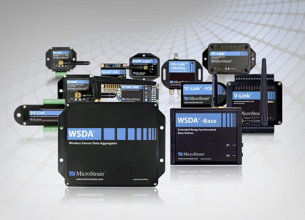
4 Overview OVERVIEW This document describes the data communications protocol for the MicroStrain Wireless Sensor Networks mxrs wireless nodes and WSDA base stations product line which includes the following devices: Device V-Link -mxrs Wireless Voltage Node G-Link -mxrs Wireless Accelerometer Node SG-Link -mxrs Wireless Strain Node DVRT-Link -mxrs Wireless Displacement Node SG-Link -OEM-S Wireless Strain Node TC-Link -mxrs -6CH Wireless Thermocouple Node TC-Link -mxrs -1CH Wireless Thermocouple Node TC-Link -mxrs OEM Wireless Thermocouple Node WSDA -Base-101 Analog Output Base Station WSDA -Base-102 RS-232 Serial Output Base Station WSDA -Base-104 USB Base Station WSDA Gateway Firmware Version 7.31 and higher 7.29 and higher 7.29 and higher 7.29 and higher 7.29 and higher 7.29 and higher 7.29 and higher 1.15 and higher 2.37 and higher 2.37 and higher 2.37 and higher 2.37 and higher If your equipment has firmware earlier than stated in the above table, there may be a requirement to upgrade in order to take full advantage of this protocol. USB Interface When communication between the WSDA -Base and the host computer is via a USB 2.0 compliant connection using a Silicon Laboratories CP210x USB-to-UART Bridge chip on the base station, the connection is supported by a Silicon Laboratories Virtual Communications Port (VCP) driver installed on the host computer. Please see the section entitled CP210x USB to UART Bridge Controller for more details. USB Virtual Communication Port Configuration Baud Rate 921, 600 Parity None Data Bits 8 Stop Bits 1 RS-232 Interface When communication between the WSDA -Base and the host computer is via an RS-232 connection, the physical layer provides the interface and there is no driver required by the base station. RS-232 Port Configuration Baud Rate 115,200 (default) or 921,600 Parity None Data Bits 8 Stop Bits 1 4
5 Commands Overview COMMANDS OVERVIEW The following two tables present a quick reference list of communication commands for controlling the base station and wireless sensor nodes. Please see the sections following for more detailed information on each command. Base Station Commands Command Byte 2 Byte 3 Byte 4 Byte 5 Byte 6 Byte 7 Ping Base Station 0x01 Read Base Station EEPROM Write Base Station EEPROM 0x73 0x78 Enable Beacon 0xBE 0xAC EEprom Address Checksum MSB LSB MSB LSB EEprom Address Value Checksum MSB LSB MSB LSB MSB LSB MSB Timestamp Disable Beacon 0xBE 0xAC 0xFF 0xFF 0xFF 0xFF LSB 5
6 Commands Overview Node Commands Command Short Ping Byte 1 0x02 Byte 2 Byte 3 Node Address MSB LSB Long Ping 0xAA 0x05 0x00 Read Node EEPROM Write Node EEPROM Initiate Sleep Mode 0xAA 0x05 0x00 0xAA 0x05 0x00 0x32 Node Address MSB LSB Stop Node 0xAA 0xFE 0x00 Arm Node for Datalogging 0xAA 0x05 0x00 Byte 4 Byte 5 Byte 6 Byte 7 Byte 8 Byte 9 Byte 10 Node Address Checksum 0x02 0x00 0x02 MSB LSB MSB LSB Byte 11 Byte 12 EEprom Node Address Checksum 0x04 0x00 0x03 Address MSB LSB MSB LSB MSB LSB EEprom Node Address Write Value Checksum 0x06 0x00 0x04 Address MSB LSB MSB LSB MSB LSB MSB LSB Node Address Checksum 0x02 0x00 0x90 MSB LSB MSB LSB Byte 13 Byte 14 Node Address 0x02 + Custom User Entered Text Checksum MSB LSB Text 0x00 0x0D (up to 50 Bytes) MSB LSB Length Byte 15 Byte 16 Byte 17 Byte 18 Trigger Armed Datalogging Download Page Erase Session Data Initiate Streaming Initiate Low Duty Cycle Initiate Synchronized Sampling Read Single Sensor 0xAA 0x05 0x00 0x05 0x06 0x38 Node Address Node Address Timestamp Checksum 0x0A 0x00 0x0E MSB LSB MSB LSB MSB LSB Page Index MSB LSB MSB LSB Node Address MSB LSB Node Address MSB LSB 0xAA 0x05 0x00 0xAA 0x05 0x00 0x03 Node Address MSB LSB 0x08 0x10 0x0C 0xFF Node Address Checksum 0x02 0x00 0x38 MSB LSB MSB LSB Node Address Checksum 0x02 0x00 0x3A MSB LSB MSB LSB 0x01 Channel # Auto-Balance Channel 0x62 Node Address Channel Target Balance # MSB LSB MSB LSB 6
7 Base Station Commands Data Format (MSB, LSB) All communication is performed at the byte level. To represent values greater than a single byte the value is broken down into several bytes, transmitted, received as several bytes and reassembled into a single value. Throughout this document the notation of MSB (Most Significant Byte) and LSB (Least Significant Byte) will be used to describe 2 byte values, as well as the start and end of 4 byte values. 2-Byte Value Example A value of 476 would yield an MSB of 1 and an LSB of 220. Decimal Hex Binary 2 Byte Value DC MSB LSB 220 DC Sample C++ Code typedef unsigned char BYTE; typedef unsigned short WORD; void ValueToMSBandLSB(WORD value, BYTE& msb, BYTE& lsb) { msb = value >> 8; //Shift 8 bits right, drop the lower byte. lsb = value & 0x00ff; //Mask out the upper byte. } WORD ValueFromMSBandLSB(BYTE msb, BYTE lsb) { return (msb << 8) lsb; //Shift msb 8 bits left, OR the lsb in. } 4-Byte Value Example A value of 1,326,214,446 would yield the following: Decimal Hex Binary 4 Byte Value 1,326,214,446 4F 0C 6D 2E (MSB) 79 4F Byte C Byte D Byte 4 (LSB) 46 2E Sample C++ Code typedef unsigned short WORD; typedef unsigned long DWORD; void ValueTo4Bytes(DWORD value, BYTE& b1, BYTE& b2, BYTE& b3, BYTE& b4) { b1 = value >> 24; //Shift 24 bits right, drop lower bytes b2 = (value >> 16) & 0xff; //Shift 16 bits right, drop lower bytes, Mask out the upper bytes } b3 = (value >> 8) & 0xff; //Shift 8 bits right, drop lower byte, Mask out the upper bytes b4 = value & 0xff; //Mask out the upper bytes DWORD ValueFrom4Bytes(BYTE b1, BYTE b2, BYTE b3, BYTE b4) { WORD hiword = (b1 << 8) b2; //Shift msb 8 bits left, OR the lsb in. WORD loword = (b3 << 8) b4; //Shift msb 8 bits left, OR the lsb in. } return (hiword << 16) loword; //Shift hiword 16 bits left, OR the loword in. 7
8 Base Station Commands Checksum Some commands and responses require or supply a checksum. The checksum is used to ensure that the data was transmitted without error. The documentation for each command or response that uses a checksum will detail how the checksum is calculated. The checksum is calculated by summing all the bytes protected by the checksum and taking the modulo N of the sum, where N is 256 for a 1 byte checksum and for a 2 byte checksum. Single Byte Checksum Example Protected Command Bytes Byte Value 10 Byte Byte 3 37 Byte Sum: 403 = Checksum: 148 = 403 MOD 256 Two Byte Checksum Example Protected Command Bytes Byte Value 10 Byte Byte 3 37 Byte Sum: 403 = Checksum: 403 = 403 MOD
9 Base Station Commands RSSI Received Signal Strength Indicator (RSSI) is a measurement of the power present in a received radio signal. Node commands such as Long Ping and Node Discovery return a true RSSI value, measured in dbm, in their response packet. This signed 1 byte value can range from -95 dbm to +5 dbm. The example below shows how to convert the value received from a node to a signed integer. typedef unsigned char BYTE; int GetRssiFromByte(BYTE valuefromeeprom) { int result; //if the byte value is < 128 if(valuefromeeprom < 128) { result = valuefromeeprom; } //if the byte value is >= 128 else { //take the (value mod 128) 128 result = (valuefromeeprom % 128) 128; } } //return the result as an integer return result; Some command responses return two RSSI values, Node RSSI and Base Station RSSI. The Node RSSI is the signal strength that the node received the command from the base station. The Base Station RSSI is the signal strength that the base station received the response back from the node. LQI The Link Quality Indicator (LQI) field is reserved for future use, and should be ignored. 9
10 Base Station Commands BASE STATION COMMANDS Ping Base Station Use the Ping Base Station command to ensure that the host computer and the Base Station are properly communicating. Command Packet: Success Response: 0x01 0x01 Fail Response: No Response 10
11 Base Station Commands Read Base Station EEPROM Use the Read Base Station EEPROM command to read the value of a specific memory address from the Base Station s EEPROM. See Base Station EEPROM Map for specific memory address details. Command Packet: 0x73 Byte 2 EEPROM address (MSB) Byte 3 EEPROM address (LSB) Byte 4 Checksum (MSB) Checksum of Bytes: Byte 5 Checksum (LSB) 2-3 Success Response: 0x73 Byte 2 Value Read (MSB) Byte 3 Value Read (LSB) Byte 4 Checksum (MSB) Checksum of Bytes: Byte 5 Checksum (LSB) 2-3 Fail Response: 0x21 See also: Data Format (MSB, LSB), Checksum 11
12 Base Station Commands Write Base Station EEPROM Use the Write Base Station EEPROM command to write a value to a specific memory address on the Base Station s EEPROM. The Read Base Station EEPROM command may be used to further verify that the value was written correctly. See Base Station EEPROM Map for specific memory address details. Command Packet: 0x78 Byte 2 EEPROM address (MSB) Byte 3 EEPROM address (LSB) Byte 4 Value to Write (MSB) Byte 5 Value to Write (LSB) Byte 6 Checksum (MSB) Checksum of Bytes: Byte 7 Checksum (LSB) 2-5 Success Response: 0x78 Byte 2 Value Written (MSB) Byte 3 Value Written (LSB) Byte 4 Checksum (MSB) Checksum of Bytes: Byte 5 Checksum (LSB) 2-3 Fail Response: 0x21 See also: Data Format (MSB, LSB), Checksum 12
13 Base Station Commands Enable Beacon Use the Enable Beacon command to turn on the beacon on the base station. The beacon is used to synchronize and start a group of nodes when performing Synchronized Sampling. Command Packet: 0xBE Byte 2 0xAC Byte 3 Timestamp (MSB) Byte 4 Timestamp Byte 2 Byte 5 Timestamp Byte 3 Byte 6 Timestamp Byte 4 (LSB) Success Response: Byte 2 0xBE 0xAC Command Packet Timestamp Bytes Bytes 3-6 in the Command Packet are Timestamp bytes. These bytes represent the current UTC time in seconds (an unsigned 64-bit integer) with byte 3 being the MSB of the timestamp, and byte 6 being the LSB of the timestamp. One should use whatever built-in method is available to the system or programming language to find the current PC time in UTC in seconds and split that into the 4 bytes shown above. See also: Synchronized Sampling 13
14 Base Station Commands Disable Beacon Use the Disable Beacon command to turn off the beacon on the base station. Sending the Stop Node command from a base station that is beaconing will automatically turn off the beacon as well. Command Packet: Byte 2 Byte 3 Byte 4 Byte 5 Byte 6 Success Response: Byte 2 0xBE 0xAC 0xFF 0xFF 0xFF 0xFF 0xBE 0xAC See also: Synchronized Sampling, Stop Node 14
15 Node Commands NODE COMMANDS Short Ping Use the Short Ping command to check the communication between the Base Station and the Node. Command Packet: Byte 2 Byte 3 Success Response: Fail Response: 0x02 Node Address (MSB) Node Address (LSB) 0x02 0x21 See also: Data Format (MSB, LSB) 15
16 Node Commands Long Ping Use the Long Ping command to check the communication between the Base Station and the Node. Command Packet: SOP(Start Of Packet) 0xAA Byte 2 Message Type 0x05 Byte 3 Address Mode 0x00 Byte 4 Node Address (MSB) 0xXX Byte 5 Node Address (MSB) 0xXX Byte 6 Payload Length 0x02 Byte 7 Command ID (MSB) 0x00 Byte 8 Command ID (LSB) 0x02 Byte 9 Checksum (MSB) 0xXX Checksum of Bytes: 0 Checksum (LSB) 0xXX 2-8 Response: The 1 byte response comes directly from the Base Station to verify that the Long Ping command was correctly received and sent to the Node. 0xAA Success Response: SOP 0xAA Byte 2 Message Type 0x07 Byte 3 Address Mode 0x02 Byte 4 Node Address (MSB) 0xXX Byte 5 Node Address (LSB) 0xXX Byte 6 Payload Length 0x02 Byte 7 Payload (not used) 0x00 Byte 8 Payload (not used) 0x00 Byte 9 Node RSSI 0xXX 0 Base Station RSSI 0xXX 1 Checksum (MSB) 0xXX Checksum of Bytes: 2 Checksum (LSB) 0xXX 2-8 Fail Response: No Response See also: Data Format (MSB, LSB), Checksum 16
17 Node Commands Read Node EEPROM Use the Read Node EEPROM command to read the value of a specific memory address from the Node s EEPROM. See Node EEPROM Map for specific memory address details. Command Packet: SOP (Start of Packet) 0xAA Byte 2 Message Type 0x05 Byte 3 Address Mode 0x00 Byte 4 Node Address (MSB) 0xXX Byte 5 Node Address (LSB) 0xXX Byte 6 Payload Length 0x04 Byte 7 Command ID (MSB) 0x00 Byte 8 Command ID (LSB) 0x03 Byte 9 EEPROM Address (MSB) 0xXX 0 EEPROM Address (LSB) 0xXX 1 Checksum (MSB) 0xXX Checksum of Bytes: 2 Checksum (LSB) 0xXX 2-10 Response: The 1 byte response comes directly from the Base Station to verify that the command was correctly received and sent to the Node. 0xAA Success Response: SOP 0xAA Byte 2 Message Type 0x00 Byte 3 Address Mode 0x00 Byte 4 Node Address (MSB) 0xXX Byte 5 Node Address (LSB) 0xXX Byte 6 Payload Length 0x02 Byte 7 Value (MSB) 0xXX Byte 8 Value (LSB) 0xXX Byte 9 LQI 0xXX 0 Base Station RSSI 0xXX 1 Checksum (MSB) 0xXX Checksum of Bytes: 2 Checksum (LSB) 0xXX 2-8 Fail Response: No Response See also: Data Format (MSB, LSB), Checksum 17
18 Node Commands Write Node EEPROM Use the Write Node EEPROM command to write a value to a specific memory address on the Node s EEPROM. See Node EEPROM Map for specific memory address details. Command Packet: SOP (Start of Packet) 0xAA Byte 2 Message Type 0x05 Byte 3 Address Mode 0x00 Byte 4 Node Address (MSB) 0xXX Byte 5 Node Address (LSB) 0xXX Byte 6 Payload Length 0x06 Byte 7 Command ID (MSB) 0x00 Byte 8 Command ID (LSB) 0x04 Byte 9 EEPROM Address (MSB) 0xXX 0 EEPROM Address (LSB) 0xXX 1 Value (MSB) 0xXX 2 Value (LSB) 0xXX 3 Checksum (MSB) 0xXX Checksum of Bytes: 4 Checksum (LSB) 0xXX 2-12 Response: The 1 byte response comes directly from the Base Station to verify that the command was correctly received and sent to the Node. 0xAA Success Response: SOP 0xAA Byte 2 Message Type 0x00 Byte 3 Address Mode 0x00 Byte 4 Node Address (MSB) 0xXX Byte 5 Node Address (LSB) 0xXX Byte 6 Payload Length 0x02 Byte 7 Write Command MSB 0x00 Byte 8 Write Command LSB 0x04 Byte 9 LQI 0xXX 0 Base Station RSSI 0xXX 1 Checksum (MSB) 0xXX Checksum of Bytes: 2 Checksum (LSB) 0xXX 2-8 Fail Response: No Response See also: Data Format (MSB, LSB), Checksum 18
19 Node Commands Initiate Sleep Mode Use the Initiate Sleep Mode command to put the Node in a low power state. Command Packet: Byte 2 0x32 Node Address (MSB) Node Address (LSB) Success Response: No Response Fail Response: No response Waking Node A Node in sleep mode periodically awakes, listens for a command, and if none is received, returns to sleep. To wake a sleeping Node, send the Stop Node command. Relevant Memory Locations Node EEPROM 66: Sleep Interval See also: Data Format (MSB, LSB), Short Ping, Stop Node 19
20 Node Commands Stop Node Use the Stop Node command to stop a Node that is either in Streaming, LDC, Synchronized Sampling, Datalogging or Sleep mode. It will also stop a Node in High Speed Streaming mode if streaming a single channel. Command Packet: SOP 0xAA Byte 2 Message Type 0xFE Byte 3 Address Mode 0x00 Byte 4 Node Address (MSB) 0xXX Byte 5 Node Address (LSB) 0xXX Byte 6 Packet Length 0x02 Byte 7 Command Byte (MSB) 0x00 Byte 8 Command Byte (LSB) 0x90 Byte 9 Checksum (MSB) 0xXX Checksum of Bytes: 0 Checksum (LSB) 0xXX 2-8 Response: The 1 byte response comes directly from the Base Station to verify that the Stop Node command was correctly received and the Base Station is attempting to stop the Node. 0xAA Success Response: The Node was stopped and will now communicate. 0x90 Byte 2 0x01 Fail Response: The Stop Node process was aborted by user sending any random byte to the Base Station. 0x21 Byte 2 0x01 The Stop Node command sends small packets as fast as possible in an attempt to communicate with the Node, and periodically checks, after 1000 packets, to see if the Node has responded to a ping request. The function will continue indefinitely until either the Node responds, or the user sends any random byte to the Base Station. The base station will send a 0x01 response when it has ceased sending the Stop Node packets, for both success and fail. Broadcast Special Case When the broadcast Node address is used, the Base Station does not check for a ping response. It will continue sending the stop Node command until interrupted by the user (any single byte sent to the Base Station). See also: Data Format (MSB, LSB), Checksum 20
21 Node Commands Arm Node (for Datalogging) Use the Arm Node command to put the node in an armed state waiting for the Trigger Armed Datalogging command. A Node will stay in this armed state for a default of 10 seconds (EEPROM adjustable). To disarm an Armed Node, use the Stop Node command. Command Packet: SOP 0xAA Byte 2 Delivery Action Byte 0x05 Byte 3 App Data Type 0x00 Byte 4 Node Address (MSB) 0xXX Byte 5 Node Address (LSB) 0xXX Byte 6 Payload Length 0x02 + # of user bytes Byte 7 Arm Command (MSB) 0x00 Byte 8 Arm Command (LSB) 0x0D Byte 9 User entered data (if applicable) 0xXX Bytes 10 through N-2 User entered data (if applicable) 0xXX Byte N-1 Checksum (MSB) 0xXX Checksum of Bytes: Byte N Checksum (LSB) 0xXX 2 (N-2) Response: A 1-byte response comes directly from the Base Station to verify that the command was received. 0xAA Success Response: SOP 0xAA Byte 2 Delivery Action Byte 0x07 Byte 3 App Data Type 0x00 Byte 4 Node Address (MSB) 0xXX Byte 5 Node Address (LSB) 0xXX Byte 6 Payload Length 0x03 Byte 7 Arm Command Received 0x00 Byte 8 Arm Command Received 0x0D Byte 9 Fail Type 0x00 0 LQI 0xXX 1 Base Station RSSI 0xXX 2 Checksum (MSB) 0xXX Checksum of Bytes: 3 Checksum (LSB) 0xXX 2-9 Fail Response: No response is received or Byte 9 (Fail Type) is not 0x00. User Entered Data The user may send up to 50 bytes with the Arm Command which can then be downloaded from the node using the Download Page command. See also: Data Format (MSB, LSB), Checksum, Trigger Armed Datalogging, Download Page 21
22 Node Commands Trigger Armed Datalogging Use the Trigger Armed Datalogging command to initiate a data capture session on-board the Node. The data will be stored in the Node s 2MB memory and may be downloaded at a later time. The Trigger Armed Datalogging command can be sent to the broadcast node address of This will be sent to all nodes on the operating frequency, but only nodes that are in the Armed state will start datalogging. This can be useful to start datalogging on multiple nodes at the same time. Command Packet: SOP 0xAA Byte 2 Delivery Action Byte 0x05 Byte 3 App Data Type 0x00 Byte 4 Node Address (MSB) 0xXX Byte 5 Node Address (LSB) 0xXX Byte 6 Payload Length 0x0A Byte 7 Trigger Command (MSB) 0x00 Byte 8 Trigger Command (LSB) 0x0E Byte 9 UTC Timestamp, seconds (MSB) 0xXX 0 UTC Timestamp, seconds 0xXX 1 UTC Timestamp, seconds 0xXX 2 UTC Timestamp, seconds 0xXX 3 UTC Timestamp, nanoseconds 0xXX 4 UTC Timestamp, nanoseconds 0xXX 5 UTC Timestamp, nanoseconds 0xXX 6 UTC Timestamp, nanoseconds (LSB) 0xXX 7 Checksum (MSB) 0xXX Checksum of Bytes: 8 Checksum (LSB) 0xXX 2-16 Success Response: No Response Fail Response: No Response 22
23 Node Commands Timestamp Bytes 9-16 make up the current UTC timestamp. Bytes 9-12 are the seconds part of the timestamp, and Bytes are the nanoseconds part of the timestamp. When downloading this data from the node, this timestamp will be transmitted in the header information and can be used to find the exact timestamp of each data point. One should use whatever built-in method is available to the system or programming language to find the current PC time in UTC, both in seconds and nanoseconds resolution, and split that into the 4 bytes shown above. Notes If a Sensor Event Driven Trigger (SEDT) is being used, the equivalent of a trigger command is automatically issued within the Node s firmware as a result of an output ceiling, or output floor being reached. Note that if SEDT is enabled, the Node will not automatically enter Sleep mode after a user inactivity timeout. During a datalogging session the Node will not respond to any commands, except the Stop Node command. If continuous datalogging is enabled, the Node will continue datalogging until it uses all available memory, it receives a Stop Node command, or it is powered off. Relevant Memory Locations Node EEPROM 12: Active Channel Mask Node EEPROM 14: Datalogging Sample Rate Node EEPROM 16: Samples per Data Set Node EEPROM 102: Continuous Datalogging Flag See also: Data Format (MSB, LSB), Checksum, Download Page, Erase Session Data, Arm Node 23
24 Node Commands Download Page When the Node is in datalogging mode, it stores the data to memory. command to retrieve a logged data session from the Node. Use the Download Page Command Packet: Command Byte 0x05 Byte 2 Node Address (MSB) 0xXX Byte 3 Node Address (LSB) 0xXX Byte 4 Page Index (MSB) 0xXX Byte 5 Page Index (LSB) 0xXX Success Response: Command Byte 0x05 Byte 2 Data Point 1 (MSB) 0xXX Byte 3 Data Point 1 (LSB) 0xXX Bytes Data Points (MSB:LSB) 0xXX Byte 264 Data Point 132 (MSB) 0xXX Byte 265 Data Point 132 (LSB) 0xXX Byte 266 Checksum (MSB) 0xXX Checksum of Bytes: Byte 267 Checksum (LSB) 0xXX Fail Response: Byte 2 0x05 0x21 Page Index Each Node contains 2MB of memory. These 2MB are mapped to 8192 pages of data, each page containing 132 data points. A data point is a 2 byte value. Pages are numbered sequentially from 0 to Page 0 always contains data points that represent the current value in each of the Node s EEPROM locations (0-254). Page 1 is a blank page and contains no usable information or data. Page 2 is the first page that will contain datalogging data. Data Sessions The Node can contain multiple consecutive datalogging sessions. Each of these sessions has a leading multi-byte header which is used to identify the start of a new datalogging session and the end of the previous session. The header contains the datalogging environment during the particular session. Session Header The datalogging session header is a multiple-byte leading string indicating the start of the next session. The header can be found anywhere on a downloaded page and it can wrap between pages. The header can be in one of many formats: 24
25 Node Commands Header Format Version 1.0 Header Format Version 1.0 has the following format: Data Point through M M + 1 M + 2 M + 3 M + 4 M + 5 M + 6 M + 7 through N N + 1 N + 2 N + 3 N + 4 N + 5 Byte Byte Data Point Value Description Value Fixed Header Identifier Trigger ID 5 1 Header Version (Major) Header Version (Minor) 7 xxx 10 + # user bytes Total # of bytes until channel data 8 xxx 9 xxx Samples per Data Set 10 xxx Session Index Active Channel Mask 1-7 Datalogging Sampling Rate 0-50 # of user entered bytes 19 xxx Up to 50 user entered bytes + 1 buffer byte if 2M xxx odd number (if any) xxx xxx xxx 2M Bytes Per Channel 2M M + 3 xxx Channel 1 Action ID 2M + 4 xxx 2M + 5 xxx Channel 1 Action Slope (byte 1) 2M + 6 xxx Channel 1 Action Slope (byte 2) 2M + 7 xxx Channel 1 Action Slope (byte 3) 2M + 8 xxx Channel 1 Action Slope (byte 4) 2M + 9 xxx Channel 1 Action Offset (byte 1) 2M + 10 xxx Channel 1 Action Offset (byte 2) 2M + 11 xxx Channel 1 Action Offset (byte 3) 2M + 12 xxx Channel 1 Action Offset (byte 4) 2M + 13 Repeat Channel Action information for xxx N channels that are active (see channel mask) N + 1 xxx # of bytes until end of header N + 2 xxx N + 3 xxx UTC Time, seconds (byte 1) N + 4 xxx UTC Time, seconds (byte 2) N + 5 xxx UTC Time, seconds (byte 3) N + 6 xxx UTC Time, seconds (byte 4) N + 7 xxx UTC Time, nanoseconds (byte 1) N + 8 xxx UTC Time, nanoseconds (byte 2) N + 9 xxx UTC Time, nanoseconds (byte 3) N + 10 xxx UTC Time, nanoseconds (byte 4) 25
26 Node Commands Header Format Version 2.0 Header Format Version 2.0 has the following format: Data Point through M M + 1 M + 2 M + 3 M + 4 M + 5 M + 6 M + 7 through N N + 1 N + 2 N + 3 N + 4 N + 5 Byte Byte Data Point Value Description Value Fixed Header Identifier Trigger ID 5 2 Header Version (Major) Header Version (Minor) 7 xxx 12 + # user bytes Total # of bytes until channel data 8 xxx 9 xxx Samples per Data Set 10 xxx Session Index Active Channel Mask 1-7 Datalogging Sampling Rate Data Type 18 xxx Unused Byte 0-50 # of user entered bytes 21 xxx Up to 50 user entered bytes + 1 buffer byte if 2M xxx odd number (if any) xxx xxx xxx 2M Bytes Per Channel 2M M + 3 xxx Channel 1 Action ID 2M + 4 xxx 2M + 5 xxx Channel 1 Action Slope (byte 1) 2M + 6 xxx Channel 1 Action Slope (byte 2) 2M + 7 xxx Channel 1 Action Slope (byte 3) 2M + 8 xxx Channel 1 Action Slope (byte 4) 2M + 9 xxx Channel 1 Action Offset (byte 1) 2M + 10 xxx Channel 1 Action Offset (byte 2) 2M + 11 xxx Channel 1 Action Offset (byte 3) 2M + 12 xxx Channel 1 Action Offset (byte 4) 2M + 13 Repeat Channel Action information for xxx N channels that are active (see channel mask) N # of bytes until end of header N N + 3 xxx UTC Time, seconds (byte 1) N + 4 xxx UTC Time, seconds (byte 2) N + 5 xxx UTC Time, seconds (byte 3) N + 6 xxx UTC Time, seconds (byte 4) N + 7 xxx UTC Time, nanoseconds (byte 1) N + 8 xxx UTC Time, nanoseconds (byte 2) N + 9 xxx UTC Time, nanoseconds (byte 3) N + 10 xxx UTC Time, nanoseconds (byte 4) 26
27 Node Commands Header Format Version 2.1 Header Format Version 2.1 has the following format: Data Point through M M + 1 M + 2 M + 3 M + 4 M + 5 M + 6 M + 7 through N N + 1 N + 2 N + 3 N + 4 N + 5 Byte Byte Data Point Value Description Value Fixed Header Identifier Trigger ID 5 2 Header Version (Major) Header Version (Minor) 7 xxx 12 + # user bytes Total # of bytes until channel data 8 xxx 9 xxx Samples per Data Set xxx Session Index Active Channel Mask 1-7 Datalogging Sampling Rate Data Type 18 xxx Unused Byte 0-50 # of user entered bytes 21 xxx Up to 50 user entered bytes + 1 buffer byte if 2M xxx odd number (if any) xxx xxx xxx 2M Bytes Per Channel 2M M + 3 xxx Channel 1 Action ID 2M + 4 xxx 2M + 5 xxx Channel 1 Action Slope (byte 1) 2M + 6 xxx Channel 1 Action Slope (byte 2) 2M + 7 xxx Channel 1 Action Slope (byte 3) 2M + 8 xxx Channel 1 Action Slope (byte 4) 2M + 9 xxx Channel 1 Action Offset (byte 1) 2M + 10 xxx Channel 1 Action Offset (byte 2) 2M + 11 xxx Channel 1 Action Offset (byte 3) 2M + 12 xxx Channel 1 Action Offset (byte 4) 2M + 13 Repeat Channel Action information for xxx N channels that are active (see channel mask) N # of bytes until end of header N N + 3 xxx UTC Time, seconds (byte 1) N + 4 xxx UTC Time, seconds (byte 2) N + 5 xxx UTC Time, seconds (byte 3) N + 6 xxx UTC Time, seconds (byte 4) N + 7 xxx UTC Time, nanoseconds (byte 1) N + 8 xxx UTC Time, nanoseconds (byte 2) N + 9 xxx UTC Time, nanoseconds (byte 3) N + 10 xxx UTC Time, nanoseconds (byte 4) 27
28 Node Commands Fixed Header Each new session is always marked with a 0xFFFF (decimal 65535) at its start. Header Version The header format that needs to be used can be determined by checking the header version bytes. Trigger ID Each datalogging session has an ID signifying how the session was started: Trigger ID Description 0 Started via a datalogging command 1 Ceiling SEDT 2 Floor SEDT 3 Ramp Up SEDT 4 Ramp Down SEDT Samples per Data Set The number of expected samples per data set. If the session was logged as a continuous datalogging session, this value is not applicable. If the session ended prematurely due to power failure or because the memory was completely filled, the value will not correspond to the actual number of samples. When parsing session data, the Samples per Data Set value should not be used to determine the end of the session. The end of the session should be determined by the start of the next session header. Header Versions 2.1 and above have the number of Samples per Data Set byte divided by 100 to allow for longer sessions. This value should be multiplied by 100 to obtain the true number of samples. Session Index Each data logging session is stored with an index. The first session s index is 1 and subsequent sessions would have consecutive index numbers. When the logged sessions are erased the index will be reset, and the first data logging session after the erase will have a Session Index of 1. Active Channel Mask The channel mask indicates the active channels that were logged in this session. Please see the section entitled Channel Mask for more details. Sampling Rate The Sample Rate that was used during the datalogging session. See the Sample Rates section for a table of the values and their corresponding sampling rates. Data Type Data type is the format which the node saves data to memory as. The following table shows the possible data values and their corresponding data types. Value Type 1, 3 bits 2 float 28
29 Node Commands User Entered Bytes Up to 50 optional user entered bytes may have been sent to the node when triggering an Armed Datalogging session. The # of user entered bytes byte specifies how many user bytes follow in the packet. If the number of user entered bytes is an odd number, there will be 1 extra buffer byte appended to the user data that should be discarded. Channel Action Channel Action shows which channel actions were enabled during data-logging for the active channels. The Action ID is a 2 byte value, while the Slope and Offset are 4 byte float values. For more information, please see the Calibration Coefficients section. Timestamp The UTC timestamp represents the starting time of the logged session (the time applied to the very first data point). The nanoseconds should be appended to the seconds of the given timestamp. Incrementing the initial UTC timestamp by the sampling rate, one can determine the exact time of each stored data point. Session Data During the actual datalogging session, the data from each active channel on the Node is written consecutively to the memory pages. For example, a Node with 3 active channels (CH1, CH3, CH4) would write data as CH1, CH3, CH4, CH1, CH3, CH4 and so forth. This data comes off the Node in the same pattern during download. Response Packet Checksum This response packet contains a checksum of bytes Relevant Memory Locations Node EEPROM 0: Current Log Page Node EEPROM 2: Current Page Offset Node EEPROM 4: Data Sets Stored See also: Data Format (MSB, LSB), Checksum, Arm Node, Trigger Armed Datalogging, Erase Session Data, Calibration Coefficients, Sample Rates 29
30 Node Commands Erase Session Data Use the Erase Session Data command to erase all datalogging sessions and data stored on the Node s memory. Command Packet: Command Byte 0x06 Byte 2 Node Address (MSB) 0xXX Byte 3 Node Address (LSB) 0xXX Byte 4 Command Byte 0x08 Byte 5 Command Byte 0x10 Byte 6 Command Byte 0x0C Byte 7 Command Byte 0xFF Success Response: Fail Response: 0x06 0x21 Response The response is returned immediately when the erasing processes begins, and no acknowledgment is sent when the process completes. The process will take approximately 5 seconds, and the Node will not respond to any commands until the erasing is complete. Completion of the erase can be detected by repeated short pinging of the Node; when the erase is complete, the Node will come back on-line and respond successfully to the ping. See also: Data Format (MSB, LSB), Trigger Armed Datalogging, Short Ping 30
31 Node Commands Initiate Real-Time Streaming Use the Initiate Real-Time Streaming command to start a real-time streaming session on a Node. The Node will respond by immediately sending a stream of data packets as the sensors are read. Command Packet: Command Byte 0x38 Byte 2 Node Address (MSB) 0xXX Byte 3 Node Address (LSB) 0xXX Response: Parsing of the streaming packets should begin with the first 0xFF byte. The 0xFF byte is the header of the first valid data packet shown below as. Each successive 0xFF indicates the start of a new data packet and the end of the previous packet. Response Packet: 0xFF Byte 2 Channel 1 Value (MSB) Byte 3 Channel 1 Value (LSB) Byte (N*2)-2 Channel N Value (MSB) Byte (N*2)-1 Channel N Value (LSB) Byte (N*2) Checksum Byte (N is the total number of channels) Terminating Streaming Continuous or Finite Streaming may be stopped at any time by issuing any byte to the Base Station. This will cause the Base Station to stop streaming. It will not however cause the Node to stop streaming. The Node will continue to stream until the set (finite) duration has elapsed or the power on the Node is cycled. The Node may be stopped from streaming by issuing the Stop Node command. End of Stream The normal end of a Finite stream is marked by 4-6 consecutive 0xAA (decimal 170) bytes. When parsing the stream, these bytes should be used as a signal that finite streaming has ended. If, during streaming, the Base Station receives no data from the Node as a result of battery draw-down in the Node, radio interference between the Base Station and the Node, the Node s power is switched off, an out-of-radio-range condition between the Base Station and the Node, etc., random noise may dribble from the Base Station; this takes the form of a few odd bytes every second or so. Response Packet Checksum This response packet contains a checksum of data bytes 2 (N-1) where N is the total number of bytes. Unlike most checksums which are 2 bytes, this checksum is a single byte. Relevant Memory Locations Node EEPROM 16: Samples per Data Set Node EEPROM 100: Continuous Streaming/LDC Flag 31
32 Node Commands Initiate Low Duty Cycle Use the Initiate Low Duty Cycle (LDC) command to put the Node in LDC mode. The Node will send an LDC packet for every sample at the defined interval for the defined sample rate. Command Packet: SOP 0xAA Byte 2 Message Type 0x05 Byte 3 Address Mode 0x00 Byte 4 Node Address (MSB) 0xXX Byte 5 Node Address (LSB) 0xXX Byte 6 Payload Length 0x02 Byte 7 Command Byte 0x00 Byte 8 Command Byte 0x38 Byte 9 Checksum (MSB) 0xXX Checksum of Bytes: 0 Checksum (LSB) 0xXX 2-8 Response: The 1 byte response comes directly from the Base Station to verify that the Initiate Low Duty Cycle command was correctly received and sent to the Node. 0xAA Data Packet: These packets are received at various, defined intervals after an initiate low duty cycle command has been sent. SOP 0xAA Byte 2 Message Type 0x07 Byte 3 Address Mode 0x04 Byte 4 Node Address(MSB) 0xXX Byte 5 Node Address(LSB) 0xXX Byte 6 Payload Length 0x0XX Byte 7 Application Identifier 0x02 Byte 8 Channel Mask 0xXX Byte 9 Sample Rate 0xXX 0 Data Type 0xXX 1 Timer Tick (MSB) 0xXX 2 Timer Tick (LSB) 0xXX 3 Channel 1 Data (MSB) 0xXX 4 Channel 1 Data (LSB) 0xXX Bytes 15 Repeat MSB and LSB bytes for the 0xXX through N-4 channels that are active Byte N-3 LQI 0xXX Byte N-2 Base Station RSSI 0xXX Byte N-1 Checksum (MSB) 0xXX Checksum of Bytes: Byte N Checksum (LSB) 0xXX 2 (N-4) 32
33 Node Commands Data Type The response packet data type can contain the following values for the type of data transmitted: 0x01 = 2 byte integers 0x02 = 4 byte floats 0x03 = 2 byte integers (non-bit-shifted) Note: A data type of 0x01 signifies a 2 byte integer that must be divided by 2 to get the correct value. Sampling Rate The Sample Rate that was used during the datalogging session. See the Sample Rates section for a table of the values and their corresponding sampling rates. Relevant Memory Locations Node EEPROM 12: Active Channel Mask Node EEPROM 16: Samples Per Data Set Node EEPROM 72: LDC / Synchronized Sampling Rate Node EEPROM 100: Unlimited Sampling Flag See also: Data Format (MSB, LSB), Checksum, Stop Node 33
34 Node Commands Initiate Synchronized Sampling The Synchronized Sampling command is very similar to the Low Duty Cycle command. Use this command to put the node into Synchronized Sampling mode. Once in this mode, the node must receive a beacon from the Base Station to begin sampling and transmitting packets of data. These packets are unique in that they contain buffered, time-stamped data. For Synchronized Sampling mode, the wireless sensor network needs to be configured so that each node is assigned an appropriate TDMA slot prior to issuing the Synchronized Sampling start command. To set up the wireless sensor network, use the Synchronized Sampling Wizard within Node Commander. Node Commander may also be used to start the network. Note: Failure to configure the network correctly will lead to wireless packets colliding, resulting in a large amount of lost data. Command Packet: SOP 0xAA Byte 2 Message Type 0x05 Byte 3 Address Mode 0x00 Byte 4 Node Address (MSB) 0xXX Byte 5 Node Address (LSB) 0xXX Byte 6 Payload Length 0x02 Byte 7 Command ID (MSB) 0x00 Byte 8 Command ID (LSB) 0x3B Byte 9 Checksum (MSB) 0xXX Checksum of Bytes: 0 Checksum (LSB) 0xXX 2-8 Response: SOP 0xAA Byte 2 DSF 0x07 Byte 3 Message Type 0x00 Byte 4 Node Address (MSB) 0xXX Byte 5 Node Address (LSB) 0xXX Byte 6 Payload Length 0x03 Byte 7 Command ID (MSB) 0x00 Byte 8 Command ID (LSB) 0x3B Byte 9 Fail Type / Open Byte 0x00 0 LQI 0xXX 1 Base Station RSSI 0xXX 2 Checksum (MSB) 0xXX Checksum of Bytes: 3 Checksum (LSB) 0xXX
35 Node Commands Data Packet: These packets are received at various, defined intervals after an initiate synchronized sampling command has been sent to an mxrs node. SOP 0xAA Byte 2 Message Type 0x07 Byte 3 Application Data Type 0x0A Byte 4 Node Address(MSB) 0xXX Byte 5 Node Address(LSB) 0xXX Byte 6 Payload Length 0xXX Byte 7 Application Identifier 0xXX Byte 8 Channel Mask 0xXX Byte 9 Sample Rate 0xXX 0 Data Type 0xXX 1 Sweep Tick (MSB) 0xXX 2 Sweep Tick (LSB) 0xXX 3 UTC Timestamp, seconds 0xXX 4 UTC Timestamp, seconds 0xXX 5 UTC Timestamp, seconds 0xXX 6 UTC Timestamp, seconds 0xXX 7 Timestamp, nanoseconds 0xXX 8 Timestamp, nanoseconds 0xXX 9 Timestamp, nanoseconds 0xXX Byte 20 Timestamp, nanoseconds 0xXX Byte 21 Channel 1 Sweep 1 Data (MSB) 0xXX Byte 22 Channel 1 Sweep 1 Data (LSB) 0xXX Byte 23 Channel 2 Sweep 1 Data (MSB) 0xXX Byte 24 Channel 2 Sweep 1 Data (MSB) 0xXX Byte 25 Channel 1 Sweep 2 Data (MSB) 0xXX Byte 26 Channel 1 Sweep 2 Data (LSB) 0xXX Byte 27 Channel 2 Sweep 2 Data (MSB) 0xXX Byte 28 Channel 2 Sweep 2 Data (LSB) 0xXX Bytes 29 through N-4 Repeat MSB and LSB bytes for the channels that are active, and for all sweeps Byte N-3 LQI 0xXX Byte N-2 Base Station RSSI 0xXX Byte N-1 Checksum (MSB) 0xXX Checksum of Bytes: Byte N Checksum (LSB) 0xXX 2 (N-4) Application Identifier The response packet application identifier can contain the following values for their current mode of operation: 0x01 = Burst Mode 0x02 = Continuous Mode 0xXX 35
36 Node Commands Data Type The response packet data type can contain the following values for the type of data transmitted: 0x01 = 2 byte integers 0x02 = 4 byte floats 0x03 = 2 byte integers (non-bit-shifted) Note: A data type of 0x01 signifies a 2 byte integer that must be divided by 2 to get the correct value. Channel Data Multiple sweeps of data per channel may be contained in one packet. The amount of sweeps in the packet can be determined via the following: Bytes Before Data = 12 (Bytes 7 20 are not channel data) Length Multiplier = 2 for 2 byte data, or 4 for float data (determined using 0 Data Type) #Sweeps = ((Payload Length Bytes Before Data) / # of Active Channels) / Length Multiplier) Timestamp/Tick The Timestamp data (Bytes 13-20) can be built into the current UTC time in nanoseconds via the following: Convert Bytes into a DWORD. This value is the current UTC time in seconds. Convert Bytes into a DWORD. This value is the current nanoseconds. Convert the first value (UTC time - Bytes 13-16) from seconds to nanoseconds, and add to it the nanoseconds (Bytes 17-20). This result is the current UTC time in nanoseconds. Although each packet may contain more than one sweep per channel, there is only one timestamp and tick acquired per packet. Therefore the tick and timestamp values must be incremented manually for each sweep within the packet. This can be done via the following: Using the sample rate of the node, determine your increment value: o If sample rate is 32 Hz, the increment is (1 / 32) = o If sample rate is 1 per 2 seconds, the increment is (1 / 0.5) = 2 o Multiply the increment by 1,000,000,000 to convert to nanoseconds. For each sweep in the packet, add the calculated value to the original timestamp. For each sweep, increment the tick by 1. Sampling Rate The Sample Rate that was used during the datalogging session. See the Sample Rates section for a table of the values and their corresponding sampling rates. Relevant Memory Locations Node EEPROM 12: Active Channel Mask Node EEPROM 16: Samples Per Data Set Node EEPROM 72: LDC / Synchronized Sampling Rate Node EEPROM 100: Unlimited Sampling Flag Node EEPROM 36: TDMA Slot Address Node EEPROM 262: Sampling Mode See also: Data Format (MSB, LSB), Checksum, Enable Beacon, Disable Beacon, Stop Node 36
37 Node Commands Read Single Sensor Use the Read Single Sensor command to read the current value of a specified channel. Command Data: Command Byte 0x03 Byte 2 Node Address (MSB) 0xXX Byte 3 Node Address (LSB) 0xXX Byte 4 0x01 0x01 Byte 5 Channel Number (1-8) 0xXX Success Response: Command Byte 0x03 Byte 2 Value (MSB) 0xXX Byte 3 Value (LSB) 0xXX Byte 4 Checksum (MSB) 0xXX Checksum of Bytes: Byte 5 Checksum (LSB) 0xXX 2-3 Fail Response: 0x21 Channel Number The Channel Number of the sensor to read. If a channel number is used that doesn t exist on the Node, erroneous response data will be returned. See also: Data Format (MSB, LSB), Checksum 37
38 Node Commands Auto-Balance Channel Use the Auto-Balance Channel command to auto-balance a particular channel on the Node. This command is only applicable to the differential channels on the V-Link, SG-Link and SG-Link OEM. Command Data: Command Byte 0x62 Byte 2 Node Address (MSB) 0xXX Byte 3 Node Address (LSB) 0xXX Byte 4 Channel to Balance (hardware specific, 1-4) 0xXX Byte 5 Target Balance Value (MSB) 0xXX Byte 6 Target Balance Value (LSB) 0xXX Success Response: No Response Fail Response: No Response Channel to Balance Channels 1, 2, 3 and/or 4 on the V-Link. Channel 1 on the SG-Link and SG-Link OEM. Target Balance Value The target balance value represents the desired sensor output value in bits, with a range of All differential inputs have a programmable offset feature that allows the user to trim sensor offset (see hardware user manual for more information.) This programmable offset can be manually altered by writing to Node EEPROM locations 26-32, or auto-tuned such that the sensor output is balanced to a user-defined target. For example, a common use is to auto-balance to mid-scale (2048 bits) to obtain maximum bipolar dynamic range. Relevant Memory Locations Node EEPROM 26: PGA Offset 1 Node EEPROM 28: PGA Offset 2 Node EEPROM 30: PGA Offset 3 Node EEPROM 32: PGA Offset 4 See also: Data Format (MSB, LSB) 38
39 Other Details OTHER DETAILS Sample Rates Synchronized Sampling / Low Duty Cycle Sample Rates The table below lists the data values and their corresponding Sample Rates that apply to the Synchronized Sampling and Low Duty Cycle sampling modes. Value Sample Rate sample per 60 minutes sample per 30 minute sample per 10 minutes sample per 5 minutes sample per 2 minutes sample per 60 seconds sample per 30 seconds sample per 10 seconds sample per 5 seconds sample per 2 seconds Hz Hz Hz Hz Hz Hz Hz Hz Hz Hz Hz Hz Armed Datalogging Sample Rates The table below lists the data values and their corresponding Sample Rates that apply to the Armed Datalogging sampling mode. Value Rate Hz Hz Hz Hz Hz 6 64 Hz 7 32 Hz 39
40 Other Details Broadcast Address A special node address referred to as the Broadcast Address exists. This Broadcast Address is Nodes shipped from the factory and any nodes in use by the customer should not be addressed as 65535; node addresses should always range between 1 and When nodes are idling and listening for commands, they are waiting for commands directed at them specifically. For example, in the case of the Short Ping command, we send 3 bytes, being an initial command byte 0x02 followed by two bytes representing the address of a unique node. This method insures that only the target node responds to the command. However, in many cases we want to command many nodes to do the same thing. To handle this situation, all nodes are always listening for commands to the Broadcast Address in addition to commands to their unique address. As an example, this special feature allows us to command many nodes to trigger a datalogging session all at the same time. This is useful to generate sensor data that has the same session start time. This Broadcast Address can most obviously be used in the following commands: Initiate Low Duty Cycle Initiate Synchronized Sampling Trigger Armed Datalogging Erase Session Data Write Node EEPROM Initiate Sleep Mode Stop Node In addition, commands for waking multiple nodes, cycling the power on multiple nodes, finding nodes with unknown addresses can all be fabricated with this special Broadcast Address. 40
41 Other Details Node Discovery The Node has a specialized function whereby it sends out two identification packets every time it is turned on. The packets are actually sent out on all 16 radio channels, allowing any Base Station within range to receive the identification packets, regardless of the Base Station s current frequency assignment. The Base Station immediately passes these packets to the host serial port. The Node will only send out a Node discovery packet when its power is cycled. Node Discovery Packet: SOP 0xAA Byte 2 Message Type (Byte 2 & 0x08) == 0 Byte 3 Address Mode 0x00 Byte 4 Node Address (MSB) 0xXX Byte 5 Node Address (LSB) 0xXX Byte 6 Packet Length 0x03 Byte 7 Radio Channel 0xXX Byte 8 Model Number (MSB) 0xXX Byte 9 Model Number (LSB) 0xXX 0 LQI 0xXX 1 Base Station RSSI 0xXX 2 Checksum (MSB) 0xXX Checksum of Bytes: 3 Checksum (LSB) 0xXX 2-9 Message Type The message type byte must be vetted to insure a valid packet. The byte must be ANDed with 0x08 and the result should be 0; if <>0, the packet is not valid. Radio Channel The radio channel value corresponds to the channel on which the Node is currently communicating. This is the same value stored in Node EEPROM 90 and sends only values that are valid within EEPROM 90. Please, reference the Node EEPROM map for position 90 to identify valid radio channels. Model Number The model number corresponds to the model number of the Node stored in Node EEPROM 112. This value identifies the type of Node that had its power cycled. Please reference the Node EEPROM map for position 112 to identify valid model numbers. See also: Data Format (MSB, LSB), Checksum 41
42 Other Details Calibration Coefficients Calibration coefficients are linear scaling filters applied to convert a channel s raw bit value to physical or engineering units. Calibration coefficients can be generated through Node Commander calibration wizards or via manual calibration by the end user. Please see the node hardware manual for more information on general calibration procedures. This documentation explains how to use existing calibration coefficients in custom software. Calibration coefficient information is stored in non-volatile EEPROM memory on the node, at locations 150 through 228 inclusive. Each channel requires 10 bytes to hold the equation ID, unit ID, slope, and offset values. Please note: 1) Calibration coefficient offset is different from a node s hardware offset settings. 2) Calibration coefficients represent a post-processing step because the conversion from bits to physical units takes place on the host computer and not on the Node. EEPROM Location Meaning EEPROM Location Meaning 150 MSB ch1 Equation ID MSB ch5 Equation ID 190 LSB ch1 Unit ID LSB ch5 Unit ID ch1 slope ch5 slope ch1 offset ch5 offset 160 MSB ch2 Equation ID MSB ch6 Equation ID 200 LSB ch2 Unit ID LSB ch6 Unit ID ch2 slope ch6 slope ch2 offset ch6 offset 170 MSB ch3 Equation ID MSB ch7 Equation ID 210 LSB ch3 Unit ID LSB ch7 Unit ID ch3 slope ch7 slope ch3 offset ch7 offset 180 MSB ch4 Equation ID MSB ch8 Equation ID 220 LSB ch4 Unit ID LSB ch8 Unit ID ch4 slope ch8 slope ch4 offset ch8 offset Below are more in depth explanations of each calibration coefficient field. 42
43 Other Details Equation ID The Equation ID is an integer value used to determine which calibration coefficient is applied to the current channel. The Equation ID and Unit ID occupy the same EEPROM location. The Equation ID is the MSB and the Unit ID is the LSB of this location. The Standard Format equation is used by MicroStrain for all new devices. The Legacy Strain and Legacy Acceleration formulas were used by previous MicroStrain software and may be present on older nodes. The Legacy equations each imply a unit type, microstrain (µε) for Legacy Strain and G's for Legacy Acceleration, while the standard equation is more flexible and doesn't enforce a specific unit. With the Standard Equation, the unit is stored separately. We recommend using the Standard Format for all custom calibration. The table below shows the three equations. Equation ID Name Equation 0x01 Bits (None) value = bits 0x01 Legacy Strain value = slope * (bits + offset) 0x02 Legacy Acceleration value = (bits offset) / slope 0x04 Standard Format value = slope * bits + offset Any other value for the Equation ID will be treated as if no calibration coefficient is applied to the channel. 43
44 Other Details Unit Type ID The Unit Type ID is an integer value used to determine which unit is applied to the current channel. The Unit Type ID value is the LSB of EEPROM 0. The table below shows the Unit Type ID values and their corresponding unit symbols and types. Unit Type ID Unit Symbol Unit Type 0x00 bits other 0x01 bits bits 0x02 ε Strain 0x03 µε microstrain 0x04 G acceleration due to gravity 0x05 m/s² meters per second squared 0x06 V volts 0x07 mv millivolts 0x08 µv microvolts 0x09 C degrees Celsius 0x0A K Kelvin 0x0B F degrees Fahrenheit 0x0C m meters 0x0D mm millimeters 0x0E µm micrometers 0x0F Lbf pound force 0x10 N Newtons 0x11 kn kilonewtons 0x12 kg kilograms 0x13 bar bar 0x14 psi pounds per square inch 0x15 atm atmospheric pressure 0x16 mmhg millimeters of mercury 0x17 Pa Pascal 0x18 MPa megapascal 0x19 kpa kilopascal 0x1A degrees degrees 0x1B degrees/s degrees per second 0x1C rad/s radians per second 0x1D % percent 0x1E rpm revolutions per minute 0x1F Hz hertz 0x20 %RH relative humidity 0x21 mv/v millivolt/volt 44
45 Other Details Slope and Offset The slope and offset are 4-byte floating point values in IEE 754-single precision format. The example below demonstrates how to read the floating point values in C++. typedef unsigned char BYTE; typedef unsigned short WORD; float MakeFloat(WORD eepromloword, WORD eepromhiword) { float f = 0; //map the float to a byte array BYTE* tmp = (BYTE*)&f; //set each byte of the float via the tmp byte pointer tmp[0] = eepromloword >> 8; tmp[1] = eepromloword & 0xFF; tmp[2] = eepromhiword >> 8; tmp[3] = eepromhiword & 0xFF; } return f; The following table displays the standard slope and offset values to convert single-ended input channels to volts, and the internal temperature sensor to degrees Celsius. Unit Slope Offset Applies To Volts V-Link Channels 5, 6, 7 SG-Link Channel 4 SG-Link OEM Channel 4 Temp C V-Link Channel 8 G-Link Channel 4 SG-Link Channel 3 SG-Link OEM Channel 3 45
46 Other Details Example Below is an example of converting EEPROM addresses to their corresponding calibration coefficient. The base address is already included in the EEPROM address. EEPROM Address Value The above EEPROM values correspond to channel 4. This can be told because the EEPROM address, EEPROM 180, corresponds to channel 4 in the EEPROM map. First determine which calibration coefficient is to be applied to channel 4. The calibration coefficient Equation ID is the MSB of EEPROM 180. The MSB of 1033 is 4, 1033 >> 8 (i.e / 256). The Equation ID therefore corresponds to the Standard Format. Thus, the formula to use is slope * bits + offset as described earlier. Second, the Unit Type ID can be calculated. The calibration coefficient Unit Type ID is the LSB of EEPROM 180. The LSB of 1033 is 9, 1033 & 0x00FF (i.e Mod 256). The Unit Type ID therefore corresponds to degrees Celsius. Next, the slope and offset must be calculated. The slope has the values and for EEPROM addresses 182 and 184, respectively. Using the formula written earlier and knowing these 4 bytes are in big endian format, the floating point equivalent is The offset has the values 5294 and for EEPROM addresses 186 and 188, respectively. Using the same formula as calculating the slope and knowing these 4 bytes are in big endian format, the floating point equivalent is As noted in the table of slopes and offsets for the Standard Format, this calibration coefficient converts incoming bits to degrees Celsius for channel 4. 46
47 Other Details Channel Mask The Channel Mask is a value contained in EEPROM address 12 of a node which dictates which of the node s channels are active. This value sets the channels that will be sampled during datalogging, streaming, low duty cycle or high speed streaming. The mask is an 8-bit value. Each of the 8 bits of the mask correspond to one of the Nodes channels. Bit 1 corresponds to channel 1, bit 2 to channel 2, bit 8 to channel 8, etc. When the bit is set to 1, the session will sample data for that channel. If the bit is set to 0, the session will not sample data for that channel. Mask Layout Bit 8 Bit 7 Bit 6 Bit 5 Bit 4 Bit 3 Bit 2 Bit 1 CH8 CH7 CH6 CH5 CH4 CH3 CH2 CH1 Example showing channels 1, 3 and 4 active Bit 8 Bit 7 Bit 6 Bit 5 Bit 4 Bit 3 Bit 2 Bit In this example the mask has been set with channels 1, 3 and 4 active (they are set with 1 s). This value equates as follows: Binary = 1101 Decimal = 13 Hex = 0x0D C++ Example Functions: typedef unsigned char BYTE; BYTE ToMask(bool ch1,bool ch2,bool ch3,bool ch4,bool ch5,bool ch6,bool ch7,bool ch8) { BYTE channelmask = 0; if(ch1){ channelmask = (1 << 0);} //channel if(ch2){ channelmask = (1 << 1);} //channel if(ch3){ channelmask = (1 << 2);} //channel if(ch4){ channelmask = (1 << 3);} //channel if(ch5){ channelmask = (1 << 4);} //channel if(ch6){ channelmask = (1 << 5);} //channel if(ch7){ channelmask = (1 << 6);} //channel if(ch8){ channelmask = (1 << 7);} //channel return channelmask; } void FromMask(BYTE channelmask) { bool ch1 = (channelmask & (1 << 0))!= 0; //channel bool ch2 = (channelmask & (1 << 1))!= 0; //channel bool ch3 = (channelmask & (1 << 2))!= 0; //channel bool ch4 = (channelmask & (1 << 3))!= 0; //channel bool ch5 = (channelmask & (1 << 4))!= 0; //channel bool ch6 = (channelmask & (1 << 5))!= 0; //channel bool ch7 = (channelmask & (1 << 6))!= 0; //channel bool ch8 = (channelmask & (1 << 7))!= 0; //channel } 47
48 Other Details void SetChannelInMask(int channel,bool enable,byte& channelmask) { //channel 1 is bit 0 channel -= 1; if(enable) { //Adding a channel and 'or' in the channel's bit. channelmask = (1<<channel); } else { //Removing a channel, mask out the channel's bit. channelmask &= 0xff ^(1<<channel); } } bool IsChannelSetInMask(int channel,byte& channelmask) { //Channel 1 is bit 0 channel-=1; //Check the channel's specific bit return (channelmask & (1<<channel))!= 0; } 48
49 Other Details CP210x USB to UART Bridge Controller The MicroStrain WSDA -Base-104 USB Station and WSDA -Base-101 Analog Output Base Station operate with a special driver installed in the operating system. The USB interface, from a physical standpoint, resides in a communication cable connecting a standard USB connector to the host. The USB communication on the base station is provided via a Silicon Laboratories CP210x USB to UART Bridge chip. The CP210x is a single-chip USB to UART bridge that converts data traffic between USB and UART formats. The chip includes a complete USB 2.0 full-speed function controller, bridge control logic and a UART interface with transmit/receive buffers and modem handshake signals. Specifications for the chip may be found at: This physical architecture is supported by a Silicon Laboratories CP210x USB to UART Bridge Virtual COM Port (VCP) driver installed on the host. This driver is required for device operation as a Virtual COM Port to facilitate host communication. The driver is normally installed during installation of MicroStrain s Node Commander software. The driver may also be downloaded from Silicon Labs at: With the installation of this driver, the developer will find that communication between host and base station will be, for all intents and purposes, typical serial communication. The various coding languages will interact as if a standard serial port existed. To determine if the driver is properly installed, connect the base station to the host and follow these steps: 1. Click Start on the Windows desktop. 2. Click Control Panel. 3. Click System icon. 4. System Properties window appears. 5. Click Hardware tab. 6. Click Device Manager. 7. Device Manger window appears. 8. Locate Ports(Com&LPT) in the tree. 9. Double-click the + to further open the Ports tree. 10. Do you see a device named 'CP210x USB to UART Bridge Controller (ComX)' or Silicon Labs CP210x USB to UART Bridge (ComX)? (with X representing a comm port number). 11. If so, the driver is installed. 12. If not, the base station is malfunctioning or the driver is not installed. 49

50 Other Details SUGGESTED DEBUGGING TOOLS We have found that software port sniffers are incredibly valuable when building applications with serial communication. Here are some of our favorites; we highly recommend their use. Serial Port Monitor Serial Port Monitor allows you to capture, display, analyze, record and replay all serial port data exchanged between the Windows application and the serial device. It can be successfully used in application development, device driver or serial hardware development and offers the powerful platform for effective coding, testing and optimization. 50

51 Other Details Comm Operator Pal Comm Operator Pal is a free tool to test and debug RS232 devices that communicated with serial port, TCP/IP or UDP. It supports data in Text, Decimal and Hex format. Data can be sent in a list automatically. Single data can be sent repeatedly. It has a built in check-sum calculator. 51
LORD MANUAL. Wireless Sensor Networks LXRS Data Communications Protocol
 LORD MANUAL Wireless Sensor Networks LXRS Data Communications Protocol 1 2013 LORD Corporation MicroStrain Sensing Systems 459 Hurricane Lane Suite 102 Williston, VT 05495 United States of America Phone:
WSDA User Guide
 User Guide Version 8500-0029 rev. 006 WSDA -1000 User Guide www.microstrain.com Little Sensors, Big Ideas. 2012 by 459 Hurricane Lane, Suite 102 Williston, VT 05495 Phone 802-862-6629 Fax 802-863-4093
3DM-GX1 Data Communications Protocol
 DCP Manual Version 3.1.02 3DM-GX1 Data Communications Protocol Little Sensors, Big Ideas www.microstrain.com 2010 by MicroStrain, Inc. 459 Hurricane Lane Suite 102 Williston, VT 05495 USA Phone: 802-862-6629
WSDA LXRS Wireless Sensor Data Aggregator
 LORD QUICK START GUIDE WSDA -1500-LXRS Wireless Sensor Data Aggregator The WSDA -1500-LXRS Wireless Sensor Data Aggregator is a data acquisition gateway used with LORD MicroStrain wireless sensor nodes
Protocol of data exchange with modem via USB interface Version
 Protocol of data exchange with modem via USB interface Version 2017.12.19 - Modem connects to USB-host as USB device of CDC class (virtual COM port in Windows, ttyusb or ttyacm in Linux) - Because real
USER GUIDE EDBG. Description
 USER GUIDE EDBG Description The Atmel Embedded Debugger (EDBG) is an onboard debugger for integration into development kits with Atmel MCUs. In addition to programming and debugging support through Atmel
HMC1022 Digital Compass
 Key Features Based on Honeywell s HMC1022 solid-state magnetic sensor Choice of 2 Interface Options (UART/I2C) Standard Pin Headers come soldered Plug and Play Module SPECIFICATIONs Angular Measuring Range
AFRecorder 4800R Serial Port Programming Interface Description For Software Version 9.5 (Last Revision )
") AFRecorder 4800R Serial Port Programming Interface Description For Software Version 9.5 (Last Revision 8-27-08) Changes from Version 9.2 1. The communication baud rate is raised to 9600. 2. Testing with
AFRecorder 4800R Serial Port Programming Interface Description For Software Version 9.5 (Last Revision 8-27-08) Changes from Version 9.2 1. The communication baud rate is raised to 9600. 2. Testing with
EDBG. Description. Programmers and Debuggers USER GUIDE
 Programmers and Debuggers EDBG USER GUIDE Description The Atmel Embedded Debugger (EDBG) is an onboard debugger for integration into development kits with Atmel MCUs. In addition to programming and debugging
LORD Data Communications Protocol Manual 3DM -GX5-10. Inertial Measurement Unit
 LORD Data Communications Protocol Manual 3DM -GX5-10 Inertial Measurement Unit MicroStrain Sensing Systems 459 Hurricane Lane Suite 102 Williston, VT 05495 United States of America Phone: 802-862-6629
2 Unifying receiver (DJ) Software Interface
 Software Interface") 1 DISCLAIMER THIS SPECIFICATION IS LICENSED AND PROVIDED BY LOGITECH "AS IS" AND ANY EXPRESS OR IMPLIED WARRANTIES, INCLUDING, BUT NOT LIMITED TO, THE IMPLIED WARRANTIES OF MERCHANTABILITY ANDFITNESS FOR
1 DISCLAIMER THIS SPECIFICATION IS LICENSED AND PROVIDED BY LOGITECH "AS IS" AND ANY EXPRESS OR IMPLIED WARRANTIES, INCLUDING, BUT NOT LIMITED TO, THE IMPLIED WARRANTIES OF MERCHANTABILITY ANDFITNESS FOR
T7 Modbus Communication User Guide
 Communication via RS232/RS485 Version 1.3 1/3/2012 1 of 17 Contents Version 1.0... 1 Terms and Conditions of License for use of gratuitous software... 3 1 General... 5 2 T7-1-MODx Registers... 6 3 T7 Modbus
3DM-GX3-35 Data Communications Protocol
 DCP Manual 8500-0014 Revision 008 3DM-GX3-35 Data Communications Protocol www.microstrain.com Little Sensors, Big Ideas 2012 by MicroStrain, Inc. 459 Hurricane Lane Williston, VT 05495 United States of
Version Action Author Date
 Version Action Author Date 1.0 Initial document KP 25.08.2013 1.1 Document review, description and register update GP 26.08.2013 1.2 Status bits, current noise floor GP 29.08.2013 1.3 Using EG100 as a
MicroStrain LXRS Wireless Base Station EEPROM Map
 MicroStrain LXRS Wireless Base Station EEPROM Map EEPROM Address (Decimal) EEPROM Address (Hexidecimal) Nomenclature Valid Ranges Factory Init Value 0 0 Reserved - 65535-2 2 Reserved - 65535-4 4 Reserved
SPI Lasers UK Limited. Serial Command Reference for the PRISM Laser Platform
 SPI Lasers UK Limited Serial Command Reference for the PRISM Laser Platform 1 of 89 Table of Contents Introduction... Connecting to the OEM Fibre Laser... Data Link Layer... Frame Structure... Data Element...
LORD USER MANUAL. WSDA -Base-104 Wireless USB Base Station
 LORD USER MANUAL WSDA -Base-104 Wireless USB Base Station MicroStrain Sensing Systems 459 Hurricane Lane Suite 102 Williston, VT 05495 United States of America Phone: 802-862-6629 Fax: 802-863-4093 http://www.microstrain.com
COMMUNICATION MODBUS PROTOCOL
 COMMUNICATION MODBUS PROTOCOL BOZZA_V04 Conto D6-Pd 05/12/2017 Pag. 1/15 CONTENTS 1.0 ABSTRACT... 2 2.0 DATA MESSAGE DESCRIPTION... 3 2.1 Parameters description... 3 2.2 Data format... 4 2.3 Description
Connecting and Calibrating a Load Cell with V-Link
 TN-W0026 MicroStrain Technical Note Connecting and Calibrating a Load Cell with V-Link V-Link and Futek LSB300 Load Cell (Applies to V-Link, SG-Link, SG-Link OEM, HS-Link ) Overview MicroStrain s V-Link
Host Controller Systems. Instruction Manual
 Host Controller Systems Instruction Manual Original Instructions 132114 Rev. I 30 July 2014 132114 Contents 1 Host Controller Systems... 3 2 SureCross DX80 Modbus Register Definitions... 4 2.1 Modbus Holding
2G Actuator Communications Protocol Document Rotary & Linear Actuators
 2752 Capitol Drive Suite #103 Sun Prairie, WI 53590 2150080 2G Actuator Packets - Rotary & Linear Revision AI Date 4/25/2018 2G Actuator Communications Protocol Document Rotary & Linear Actuators DOCUMENT
HouseLink HL-10E. Installation and Operation Manual Modbus TCP and XML
 HouseLink HL-10E Installation and Operation Manual Modbus TCP and XML HouseLink HL-10E 4/25/2018 Table of Contents Installation Overview... 3 Components... 3 BinTrac Indicator... 3 Load Cell Bracket...
SAM4 Reset Controller (RSTC)
") APPLICATION NOTE AT06864: SAM4 Reset Controller (RSTC) ASF PROGRAMMERS MANUAL SAM4 Reset Controller (RSTC) This driver for SAM devices provides an interface for the configuration and management of the
APPLICATION NOTE AT06864: SAM4 Reset Controller (RSTC) ASF PROGRAMMERS MANUAL SAM4 Reset Controller (RSTC) This driver for SAM devices provides an interface for the configuration and management of the
3DM-GQ4-45 Tactical Grade GNSS-Aided Inertial Navigation System (GNSS/INS)
") LORD QUICK START GUIDE 3DM-GQ4-45 Tactical Grade GNSS-Aided Inertial Navigation System (GNSS/INS) The 3DM-GQ4-45 is a high-performance, GNSS-Aided Inertial Navigation System (GNSS/INS) that combines micro
LORD QUICK START GUIDE 3DM-GQ4-45 Tactical Grade GNSS-Aided Inertial Navigation System (GNSS/INS) The 3DM-GQ4-45 is a high-performance, GNSS-Aided Inertial Navigation System (GNSS/INS) that combines micro
Application Note. Introduction AN2471/D 3/2003. PC Master Software Communication Protocol Specification
 Application Note 3/2003 PC Master Software Communication Protocol Specification By Pavel Kania and Michal Hanak S 3 L Applications Engineerings MCSL Roznov pod Radhostem Introduction The purpose of this
WiMOD LR Base Plus Host Controller Interface
 WiMOD LR Base Plus Host Controller Interface Specification Version 1.2 Document ID: 4000/40140/0125 IMST GmbH Carl-Friedrich-Gauß-Str. 2-4 47475 KAMP-LINTFORT GERMANY Introduction Document Information
DGILib USER GUIDE Atmel-42771A-DGILib_User Guide-09/2016
 DGILib USER GUIDE Table of Contents 1. Description...3 2. API...4 2.1. Discovery...4 2.1.1. initialize_status_change_notification... 4 2.1.2. uninitialize_status_change_notification... 4 2.1.3. register_for_device_status_change_notifications...4
QUICK START GUIDE MODEL DXA/DXI 100/200 DIGITAL ACCELEROMETER & INCLINOMETER JEWELL INSTRUMENTS, LLC. 850 Perimeter Road Manchester, NH 03103
 QUICK START GUIDE MODEL DXA/DXI 100/200 DIGITAL ACCELEROMETER & INCLINOMETER JEWELL INSTRUMENTS, LLC 850 Perimeter Road Manchester, NH 03103 PHONE: (800) 227-5955 E-MAIL: sales@jewellinstruments.com DXA-DXI
ED1021 I/O Expander with UART interface & analog inputs
 Preliminary Highlights 2.7V 5V power supply range. 12 GPIOs. Up to 40mA maximum current in each output except GPIO8 (up to a total device current of 175mA). Most GPIOs can be an input to a 10bit ADC. Simple
imetos LoRa Data payload structure
 imetos LoRa Data payload structure Pessl Instruments, GmbH Version 1.0, 06-2018 Content 1. SCOPE OF THIS DOCUMENT... 2 2. PARSING THE DATA FROM THE PAYLOAD VERSUS API DATA ACCESS... 3 3. IMETOS LORA FIRMWARE
QSB Command List. Document Version /15/2017
 QSB Command List Document Version 1.25 8/15/2017 1 of 17 Terms and Conditions of License for use of gratuitous software Thank you for purchasing US Digital products. By downloading or using US Digital
WiMOD LR Base Host Controller Interface
 WiMOD LR Base Host Controller Interface Specification Version 1.7 Document ID: 4100/40140/0062 IMST GmbH Carl-Friedrich-Gauß-Str. 2-4 47475 KAMP-LINTFORT GERMANY Introduction Document Information File
Specification E2 Interface
 Specification E2 Interface Version 4.1 Name Date Created: Robert Mayr. 15.04.2011 Checked: Haider A. 15.04.2011 Approved: Reason for change: Text corrections TABLE OF CONTENTS 1 INTRODUCTION... 3 1.1 Overview..................................................................................................................
JMY504M User's Manual
 JMY504M User's Manual (Revision 3.42) Jinmuyu Electronics Co. LTD 2011/6/28 Please read this manual carefully before using. If any problem, please mail to: Jinmuyu@vip.sina.com Contents 1 Product introduction...
USER GUIDE. Wireless Production Test Reference Protocol Specification Document. Atmel MCU Wireless. Description
 USER GUIDE Wireless Production Test Reference Protocol Specification Document Atmel MCU Wireless Description This document explains the serial protocol used for communication between various blocks of
B Interface description 12.01/
 B 95.3530.2 Interface description 12.01/00340396 Contents 1 Introduction 1.1 Preface... 3 1.2 Typographical conventions... 4 1.2.1 Warning signs... 4 1.2.2 Note signs... 4 1.2.3 Presentation... 4 2 Protocol
Preliminary File System User Manual
 GHI Electronics, LLC 501 E. Whitcomb Ave. Madison Heights, Michigan 48071 Phone: (248) 397-8856 Fax: (248) 397-8890 www.ghielectronics.com Preliminary File System User Manual Where Hardware Meets Software
XStream AT Commands. Advanced Manual v South 520 West, Suite 180 Lindon, UT Phone: (801) Fax: (801)
 Fax: (801)") XStream AT Commands XStream Product Family Modes of Operation Radio Modem Configuration Advanced Networking and Security Appendices Advanced Manual v4.29 Standard AT Commands Configurations Products Supported:
XStream AT Commands XStream Product Family Modes of Operation Radio Modem Configuration Advanced Networking and Security Appendices Advanced Manual v4.29 Standard AT Commands Configurations Products Supported:
CODA Online Data Formats
 CODA Online Data Formats Evio Header Formats Bank : 32 bits MSB (31) LSB (0) Length (32 bit words, exclusive) Tag (16 bits) (2) Type (6) Num (8) Segment : Padding Tag (8 bits) (2) Type (6) Length (16)
EVShield Interface Specifications
 EVShield Advanced Development Guide v1.0 EVShield Interface Specifications Power Specs: EVShield can be powered from external power supply. Max Power Rating: 10.5 Volts DC Minimum 6.6 Volts DC needed to
CEL MeshConnect ZICM35x Test Tool User Guide
 User Guide 0011-00-17-02-000 CEL MeshConnect ZICM35x Test Tool User Guide CEL MeshConnect ZICM35x Test Tool User Guide Introduction CEL s MeshConnect EM357 Mini Modules combine high performance RF solutions
BLUETOOTH MOVEMENT AND SHOCK LOGGER API DOCUMENTATION. Version 2.0.1
 BLUETOOTH MOVEMENT AND SHOCK LOGGER API DOCUMENTATION Version 2.0.1 BLUE MAESTRO S STANDARD LICENSE AND DISCLAIMER Copyright 2016 Blue Maestro Limited. All Rights Reserved. The copyright in the software
Sure Cross User Configuration Tool (UCT)
") Sure Cross User Configuration Tool (UCT) Instruction Manual Original Instructions 140628 Rev. J 6 July 2018 Banner Engineering Corp. All rights reserved 140628 Contents 1 Sure Cross User Configuration
Sure Cross User Configuration Tool (UCT) Instruction Manual Original Instructions 140628 Rev. J 6 July 2018 Banner Engineering Corp. All rights reserved 140628 Contents 1 Sure Cross User Configuration
SensorConnect Changelog. Updated:
 SensorConnect Changelog Updated: 2018-09-24 v9.12.11 (2018-09-24) Sensor Output Mode: The latest firmware for the G-Link-200 allows configuring the device to output Tilt channels. Last Known State: The
RS232-ADC16/24 Manual
 RS232-ADC16/24 Manual Version 1.11 Copyright taskit GmbH 2009 www.taskit.de Page 1/22 Table of contents 1 Features...3 2 Introduction...3 3 Bringing into service...4 4 Application Sample...5 5 Frame layout...6
Logitech hidpp 1.0 excerpt for public release
 1 DISCLAIMER THIS SPECIFICATION IS LICENSED AND PROVIDED BY LOGITECH "AS IS" AND ANY EXPRESS OR IMPLIED WARRANTIES, INCLUDING, BUT NOT LIMITED TO, THE IMPLIED WARRANTIES OF MERCHANTABILITY ANDFITNESS FOR
IP-AD Channel 500 khz Simultaneous IndustryPack Module REFERENCE MANUAL Version 1.4 June 2003
 IP-AD4500 4 Channel 500 khz Simultaneous IndustryPack Module REFERENCE MANUAL 799-14-000-4000 Version 1.4 June 2003 ALPHI TECHNOLOGY CORPORATION 6202 S. Maple Avenue #120 Tempe, AZ 85283 USA Tel: (480)
Data Communication Protocol Host Computer to FAS-A
 Data Communication Protocol Host Computer to FAS-A Overview This section codifies the communication protocol between an FAS-A and a host computer. Utilizing these protocols the host computer can 1) acquire
JDICON 1000 JDICON B Interface Description 3.99/ Universal Process Controller. Universal Profile Controller
 JDICON 1000 Universal Process Controller JDICON 1001 Universal Profile Controller B 70.3560.2 Interface Description 3.99/00316584 Contents 1 Introduction 1.1 Preliminary remarks... 3 1.2 Typographical
modpoll is a command line based Modbus master simulator and test utility. It is free software.
 Read Me Notes Revision 3.4, 2013-01-30 This Read Me file contains last-minute product information for the FieldTalk modpoll utility. modpoll is a command line based Modbus master simulator and test utility.
LabVIEW Driver. User guide Version
 LabVIEW Driver User guide Version 1.0.0 2016 Table of Contents Version History...3 Copyright...4 Software License...5 Operational Safety...6 Warranty and Support...7 Introduction...8 Requirements...9 How
COMMUNICATION MODBUS PROTOCOL MF96001 / 021 NEMO 96HD
 COMMUNICATION MODBUS PROTOCOL MF96001 / 021 NEMO 96HD PR106 20/10/2016 Pag. 1/31 Contents 1.0 ABSTRACT... 2 2.0 DATA MESSAGE DESCRIPTION... 3 2.1 Parameters description... 3 2.2 Data format... 4 2.3 Description
COMMUNICATION MODBUS PROTOCOL
 COMMUNICATION MODBUS PROTOCOL CE4DT36 CONTO D4 Pd (3-single phase) PR134 20/10/2016 Pag. 1/11 Contents 1.0 ABSTRACT... 2 2.0 DATA MESSAGE DESCRIPTION... 3 2.1 Parameters description... 3 2.2 Data format...
FLAMEBOSS 300 MANUAL
 FLAMEBOSS 300 MANUAL Version 2.1 Download latest at FlameBoss.com/manuals WARNING: Important Safety Instructions It is important for the safety of persons to follow these instructions. Save these instructions.
Dual Serial Shield User Manual
 Dual Serial Shield User Manual PN: 2050 Berkshire Products, Inc. Phone: 770-271-0088 http://www.bkp-store.com/ Rev: 1.00 Copyright 2013 Table of Contents 1 Introduction... 2 1.1 XB compatibility... 2 2
HDV100A3 Command Response Protocol
 HDV100A3 Command Response Protocol Documentation Number: HDV100A3-4115m International Headquarters B+B SmartWorx 707 Dayton Road -- P.O. Box 1040 -- Ottawa, IL 61350 USA Phone (815) 433-5100 -- General
Small Logger File System
 Small Logger File System (http://www.tnkernel.com/) Copyright 2011 Yuri Tiomkin Document Disclaimer The information in this document is subject to change without notice. While the information herein is
LORD Data Communications Protocol Manual 3DM -GX5-35. Attitude and Heading Reference Unit (AHRS) with GNSS
 with GNSS") LORD Data Communications Protocol Manual 3DM -GX5-35 Attitude and Heading Reference Unit (AHRS) with GNSS MicroStrain Sensing Systems 459 Hurricane Lane Suite 102 Williston, VT 05495 United States of America
LORD Data Communications Protocol Manual 3DM -GX5-35 Attitude and Heading Reference Unit (AHRS) with GNSS MicroStrain Sensing Systems 459 Hurricane Lane Suite 102 Williston, VT 05495 United States of America
COMMUNICATION MODBUS PROTOCOL
 COMMUNICATION MODBUS PROTOCOL CE4DMID31 / CE4DMID21 CONTO D4 Pd MID PR123 20/10/2016 Pag. 1/9 Contents 1.0 ABSTRACT... 2 2.0 DATA MESSAGE DESCRIPTION... 3 2.1 Parameters description... 3 2.2 Data format...
LORD Data Communications Protocol Manual 3DM -CV5-15. Vertical Reference Unit
 LORD Data Communications Protocol Manual 3DM -CV5-15 Vertical Reference Unit MicroStrain Sensing Systems 459 Hurricane Lane Suite 102 Williston, VT 05495 United States of America Phone: 802-862-6629 www.microstrain.com
Embit Binary Interface - WMBus Specific Documentation. embit s.r.l.
 Embit Binary Interface - WMBus Specific Documentation embit s.r.l. Document information Versions & Revisions Revision Date Author Comments 1.0 22/01/2010 A. Sala Initial version 1.1 22/01/2010 C. Biagi
PRECISION ENERGY METER. DATALOGGING (-L / -DL Option) USER MANUAL
 USER MANUAL") PRECISION ENERGY METER DATALOGGING (-L / -DL Option) USER MANUAL Installation Considerations Installation and maintenance of the WattsOn device must only be performed by qualified, competent personnel
PRECISION ENERGY METER DATALOGGING (-L / -DL Option) USER MANUAL Installation Considerations Installation and maintenance of the WattsOn device must only be performed by qualified, competent personnel
Embit Binary Interface - IEEE Specific Documentation. embit s.r.l.
 Embit Binary Interface - IEEE 802.15.4-Specific Documentation embit s.r.l. Document information Versions & Revisions Revision Date Author Comments 1.0 A. Sala First release 1.1 14/12/2012 C. Biagi Minor
1. Implemented CM11 protocol
 1. Implemented CM11 protocol 1.1. Housecodes and Device Codes. The housecodes and device codes range from A to P and 1 to 16 respectively although they do not follow a binary sequence. The encoding format
National Instruments Analog-to-Digital (NI A2D) Module Manual
 Module Manual") Particle Analysis and Display System (PADS): National Instruments Analog-to-Digital (NI A2D) Module Manual DOC-0292 Rev A PADS 3.5, NI A2D Module 3.5 2545 Central Avenue Boulder, CO 80301 USA C O P Y R
Particle Analysis and Display System (PADS): National Instruments Analog-to-Digital (NI A2D) Module Manual DOC-0292 Rev A PADS 3.5, NI A2D Module 3.5 2545 Central Avenue Boulder, CO 80301 USA C O P Y R
Open Source Used In c1101 and c1109 Cisco IOS XE Fuji
 Open Source Used In c1101 and c1109 Cisco IOS XE Fuji 16.8.1 Cisco Systems, Inc. www.cisco.com Cisco has more than 200 offices worldwide. Addresses, phone numbers, and fax numbers are listed on the Cisco
Data sheet Wireless UART firmware version 4
 Data sheet Wireless UART firmware version 4 BLUETOOTH is a trademark owned by Bluetooth SIG, Inc., U.S.A. and licensed to Free2move Rev: 05 December 2006 Table of contents 1 GENERAL INFORMATION...4 1.1
Application Note: JN-AN-1003 JN51xx Boot Loader Operation
 Application Note: JN-AN-1003 JN51xx Boot Loader Operation This Application Note describes the functionality of the boot loaders for the NXP, JN514x and wireless microcontrollers, covering the following
LXRS and LXRS+ Wireless Sensor Protocol
 LORD TECHNICAL NOTE LXRS and LXRS+ Wireless Sensor Protocol Using LXRS and LXRS+ For Long-Term Monitoring and High Bandwidth Test and Measurement Introduction LORD Sensing has developed and deployed two
IF96017 MODBUS COMMUNICATION PROTOCOL
 CONTENTS 1.0 ABSTRACT 04/07/14 Pagina 1 di 9 MULTIFUNCTION FIRMWARE 1.00 COMMUNICATION PROTOCOL IF96017 MODBUS COMMUNICATION PROTOCOL 2.0 DATA MESSAGE DESCRIPTION 2.1 Parameters description 2.2 Data format
TECH TIP. Tritex Modbus Protocol Specification
 Tritex Modbus Protocol Specification Introduction This document describes Tritex s implementation of the MODBUS communication protocol used for transferring data between a serial host and an Exlar drive.
EEPROM Emulation with the ez80f91 MCU. Discussion
 Application Note EEPROM Emulation with the ez80f91 MCU AN015803-0608 Abstract This Application Note describes a method to utilize a portion of Zilog s ez80acclaimplus! MCU s Flash memory to emulate the
Using LPC11Axx EEPROM (with IAP)
") Rev. 2 1 July 2012 Application note Document information Info Content Keywords LPC11A02UK ; LPC11A04UK; LPC11A11FHN33; LPC11A12FHN33; LPC11A12FBD48; LPC11A13FHI33; LPC11A14FHN33; LPC11A14FBD48; LPC11Axx,
Rev. 2 1 July 2012 Application note Document information Info Content Keywords LPC11A02UK ; LPC11A04UK; LPC11A11FHN33; LPC11A12FHN33; LPC11A12FBD48; LPC11A13FHI33; LPC11A14FHN33; LPC11A14FBD48; LPC11Axx,
JUMO Quantrol LC100/LC200/LC300
 JUMO Quantrol LC100/LC200/LC300 Universal PID Controller Series B 702030.2.0 Interface Description Modbus 2013-05-27/00600589 Content 1 Introduction................................................ 5 1.1
StorageGRID Webscale NAS Bridge Management API Guide
 StorageGRID Webscale NAS Bridge 2.0.3 Management API Guide January 2018 215-12414_B0 doccomments@netapp.com Table of Contents 3 Contents Understanding the NAS Bridge management API... 4 RESTful web services
JUMO ctron 04/08/16. Compact controller with timer and ramp function. B Interface Description Modbus /
 JUMO ctron 04/08/16 Compact controller with timer and ramp function 702071 702072 702074 B 70.2070.2.0 Interface Description Modbus 2008-08-11/00492538 Contents 1 Introduction 5 1.1 Preface... 5 1.2 Typographical
COMMUNICATION MODBUS PROTOCOL
 COMMUNICATION MODBUS PROTOCOL MFD4E06 - NEMO-D4e PR146 08/03/2018 Pag. 1/16 CONTENTS 1.0 ABSTRACT... 2 2.0 DATA MESSAGE DESCRIPTION... 3 2.1 Parameter description... 3 2.2 Data format... 4 2.3 Description
VINCULUM-BASED TEMPERATURE / HUMIDITY / VOLTAGE DATA LOGGER FEATURES:
 DLP-VLOG *LEAD-FREE* VINCULUM-BASED TEMPERATURE / HUMIDITY / VOLTAGE DATA LOGGER FEATURES: Virtually Unlimited Data Storage Utilizing FTDI s New Vinculum USB Host IC Data Logged to USB Flash Drive Low-Power
USER MANUAL Z-SG / Z-SG-L. Advanced Digital Strain gauge converter. Via Austria, PADOVA ITALY
 USER MANUAL Z-SG / Z-SG-L Advanced Digital Strain gauge converter SENECA s.r.l. Via Austria, 26 35127 PADOVA ITALY Tel. +39.049.8705355 8705359 Fax. +39.049.8706287 Web site: www.seneca.it Technical assistance:
AC4790 User s Guide Version 2.0
 AC4790 User s Guide Option 2 Hong Kong: +852-2923-0610 REVISION HISTORY Revision Date Description Approved By 1.0 Initial Release Chris Downey 1.1 Changes and Revisions Chris Downey 2.0 19 Dec 2013 Separated
Conto D1 MODBUS COMMUNICATION PROTOCOL
 ENERGY METER Conto D1 MODBUS COMMUNICATION PROTOCOL 4/03/15 Pagina 1 di 7 FIRMWARE CONTENTS 1.0 ABSTRACT 2.0 DATA MESSAGE DESCRIPTION 2.1 Parameters description 2.2 Data format 2.3 Description of CRC calculation
Space engineering. SpaceWire Protocols
 Space engineering SpaceWire Protocols This ECSS is a draft standard circulated for xxxxxxxxxx. It is therefore subject to change without notice and may not be referred to as an ECSS Standard until published
Preliminary F40 SoC Datasheet
 GHI Electronics, LLC 501 E. Whitcomb Ave. Madison Heights, Michigan 48071 Phone: (248) 397-8856 Fax: (248) 397-8890 www.ghielectronics.com Preliminary F40 SoC Datasheet Where Hardware Meets Software GHI
WIRELESS RECEIVER WRM-TS. Rev. 1.0c
 WIRELESS RECEIVER WRM-TS U S E R M A N U A L Rev. 1.0c TABLE OF CONTENTS 1. General information 3 2. Technical parameters 4 3. Normal mode of operation 4 4. Command reference 5 4.1. Command get 6 4.2.
RS-232 Control of the Advantage EQ281/8, EQ282/8 and Advantage SMS200
 RS-232 Control of the Advantage EQ281/8, EQ282/8 and Advantage SMS200 Biamp Systems, 14130 N.W. Science Park, Portland, Oregon 97229 U.S.A. (503) 641-7287 an affiliate of Rauland-Borg Corp. Introduction
InfoTag KE28xx Communications for 186 CPU Firmware Version 4
 InfoTag KE28xx Communications for 186 CPU Firmware Version 4 *KE28xx models include: KE2800, KE2852, KE2853, KE2856 This document applies to printer firmware versions 4.x only. Note that changes made to
MassaSonic PulStar and FlatPack Series Ultrasonic Level Sensors. Serial Communications Guide
 Guide to MassaSonic PulStar & FlatPack Sensor Serial Communications Page 1 of 26 MassaSonic PulStar and FlatPack Series Ultrasonic Level Sensors Serial Communications Guide March 23, 2016 Tel: 781-749-4800
DMTME Multimeters. Communication protocol. Technical specification V1.2 ABB
 DMTME Multimeters Communication protocol ABB 1 Setting up DMTME serial communication.3 1.1 Serial network ID programming...3 1.2 RS-485 communication interface...3 1.3 Serial line connection...3 2 Communication
LORD MANUAL 3DM-GX4-45. Data Communications Protocol
 LORD MANUAL 3DM-GX4-45 Communications Protocol 1 2014 LORD Corporation MicroStrain Sensing Systems 459 Hurricane Lane Suite 102 Williston, VT 05495 United States of America Phone: 802-862-6629 Fax: 802-863-4093
LORD MANUAL 3DM-RQ1-45. Data Communications Protocol
 LORD MANUAL 3DM-RQ1-45 Communications Protocol 1 2013 LORD Corporation MicroStrain Sensing Systems 459 Hurricane Lane Suite 102 Williston, VT 05495 United States of America Phone: 802-862-6629 Fax: 802-863-4093
Serial Communications Guide
 M-5000 Smart Ultrasonic Sensor Serial Communications Guide Page 1 of 14 Serial Communications Guide MassaSonic TM M-5000 Smart Ultrasonic Sensors MASSA PRODUCTS CORPORATION 280 Lincoln Street Hingham,
ED1021 I/O Expander with UART interface & analog inputs
 Preliminary Highlights 4.5V 5.5V power supply range. 12 GPIOs. Up to 40mA maximum current in each output except GPIO8 (up to a total device current of 175mA). Most GPIOs can be an input to a 10bit ADC.
MODBUS MANUAL For the AccUView UV Transmission Monitor
 MODBUS MANUAL For the AccUView UV Transmission Monitor HF scientific, inc. 3170 Metro Parkway Ft. Myers, FL 33916 Phone: 239-337-2116 Fax: 239-332-7643 E-Mail: info@hfscientific.com Website: www.hfscientific.com
INSTEON Hidden Door Sensor
 Developer Notes INSTEON Door Sensor Developer Notes INSTEON Hidden Door Sensor Version 005 October 18, 2013 Revision History Rev Date Comments 001 4/15/13 Initial Release 002 8/2/13 Updated s 003 9/6/13
RapidIO Interconnect Specification Part 11: Multicast Extensions Specification
 RapidIO Interconnect Specification Part 11: Multicast Extensions Specification Rev. 1.3.1, 06/2005 Copyright RapidIO Trade Association RapidIO Trade Association Revision History Revision Description Date
APPLICATION NOTE 9.15
 APPLICATION NOTE 9.15 U2DP Driver Development Specification Rev. 02/14/2002 80 Arkay Drive Hauppauge, NY 11788 (631) 435-6000 FAX (631) 273-3123 Copyright SMSC 2004. All rights reserved. Circuit diagrams
This document is for information purposes only and is subject to change without notice.
 Notice WALCHEM, Iwaki America Inc. (hereinafter Walchem ) Boynton Road, Holliston, MA USA () - All Rights Reserved Printed in USA Proprietary Material The information and descriptions contained herein
Conto D2 COMMUNICATION PROTOCOL CONTENTS 1.0 INTRODUCTION
 PR 121 rev. 0 11/11/2011 Pagina 1 di 9 ELECTRICITY ENERGY METER FIRMWARE 1.6 Conto D2 COMMUNICATION PROTOCOL CONTENTS 1.0 INTRODUCTION 2.0 DATA MESSAGE DESCRIPTION 2.1 Data field description 2.2 Data format
AN4872 Application note
 Application note BlueNRG-1 and BlueNRG-2 UART bootloader protocol Introduction The BlueNRG-1 and BlueNRG-2 are very low power Bluetooth low energy (BLE) single-mode systemson-chip, compliant with Bluetooth
Version. Table of Contents
 NAP Protocol 1.0 Version Version Date By Comment v1.0 24.01.2011 JP Release version of NAP documentation. Table of Contents 1 Basic concepts...3 1.1 Usage info...3 1.2 Length byte...3 1.3 Literal characters...4