(renamed the "EIA232 Standard" in the early 1990 s)
|
|
|
- Loreen McCormick
- 6 years ago
- Views:
Transcription
1 Contents (renamed the "EIA232 Standard" in the early 1990 s) Written by Christopher E. Strangio Copyright by CAMI Research Inc., Lexington, Massachusetts Send Us Your Comments... What is EIA232? Likely Problems when Using an EIA232 Interface Pin Assignments Cable Wiring Examples (New!) Signal Definitions Signal Ground and Shield Primary Communications Channel Secondary Communications Channel Modem Status and Control Signals Transmitter and Receiver Timing Signals Channel Test Signals Electrical Standards Common Signal Ground Signal Characteristics Signal Timing Accepted Simplifications of the Standard Pin Description Index References to EIA Publications Back to CableEye Home Page What is EIA232? Next Topic TOC In the early 1960s, a standards committee, today known as the Electronic Industries Association, developed a common interface standard for data communications equipment. At that time, data communications was thought to mean digital data exchange between a centrally located mainframe computer and a remote computer terminal, or possibly between two terminals without a computer involved. These devices were linked by telephone voice lines, and consequently required a modem at each end for signal translation. While simple in concept, the many opportunities for data error that occur when transmitting data through an analog channel require a relatively complex design. It was thought that a standard was needed first to ensure reliable communication, and second to enable the
2 interconnection of equipment produced by different manufacturers, thereby fostering the benefits of mass production and competition. From these ideas, the RS232 standard was born. It specified signal voltages, signal timing, signal function, a protocol for information exchange, and mechanical connectors. Over the 40+ years since this standard was developed, the Electronic Industries Association published three modifications, the most recent being the EIA232E standard introduced in Besides changing the name from RS232 to EIA232, some signal lines were renamed and various new ones were defined, including a shield conductor. Likely Problems when Using an EIA232 Interface Next Topic Previous Topic TOC During this 40-year-long, rapidly evolving period in electronics, manufacturers adopted simplified versions of this interface for applications that were impossible to envision in the 1960s. Today, virtually all contemporary serial interfaces are EIA232-like in their signal voltages, protocols, and connectors, whether or not a modem is involved. Because no single "simplified" standard was agreed upon, however, many slightly different protocols and cables were created that obligingly mate with any EIA232 connector, but are incompatible with each other. Most of the difficulties you will encounter in EIA232 interfacing include at least one of the following: 1 - The absence or misconnection of flow control (handshaking) signals, resulting in buffer overflow or communications lock-up. 2 - Incorrect communications function (DTE versus DCE) for the cable in use, resulting in the reversal of the Transmit and Receive data lines as well as one or more handshaking lines. 3 - Incorrect connector gender or pin configuration, preventing cable connectors from mating properly. Fortunately, EIA232 driver circuitry is highly tolerant of misconnections, and will usually survive a drive signal being connected to ground, or two drive signals connected to each other. In any case, if the serial interface between two devices is not operating correctly, disconnect the cable joining this equipment until the problem is isolated. Pin Assignments Next Topic Previous Topic TOC Go to DTE Pinout (looking into the computer s serial connector) Go to DCE Pinout (looking into the modem s serial connector) If the full EIA232 standard is implemented as defined, the equipment at the far end of the connection is
3 named the DTE device (Data Terminal Equipment, usually a computer or terminal), has a male DB25 connector, and utilizes 22 of the 25 available pins for signals or ground. Equipment at the near end of the connection (the telephone line interface) is named the DCE device (Data Circuit-terminating Equipment, usually a modem), has a female DB25 connector, and utilizes the same 22 available pins for signals and ground. The cable linking DTE and DCE devices is a parallel straight-through cable with no cross-overs or self-connects in the connector hoods. If all devices exactly followed this standard, all cables would be identical, and there would be no chance that an incorrectly wired cable could be used. This drawing shows the orientation and connector types for DTE and DCE devices: EIA232 communication function and connector types for a personal computer and modem. DCE devices are sometimes called "Data Communications Equipment" instead of Data Circuit-terminating Equipment. Here is the full EIA232 signal definition for the DTE device (usually the PC). The most commonly used signals are shown in bold. [back to Pin Assignments description]
4 Copyright CAMI Research Inc. This shows the full EIA232 signal definition for the DCE device (usually the modem). The most commonly used signals are shown in bold. [back to Pin Assignments description]
5 Copyright CAMI Research Inc. Many of the 22 signal lines in the EIA232 standard pertain to connections where the DCE device is a modem, and then are used only when the software protocol employs them. For any DCE device that is not a modem, or when two DTE devices are directly linked, far fewer signal lines are necessary. You may have noticed in the pinout drawings that there is a secondary channel which includes a duplicate set of flow-control signals. This secondary channel provides for management of the remote modem, enabling baud rates to be changed on the fly, retransmission to be requested if a parity error is detected, and other control functions. This secondary channel, when used, is typically set to operate at a very low baud rate in comparison with the primary channel to ensure reliability in the control path. In addition, it may operate as either a simplex, half-duplex, or full-duplex channel, depending on the capabilities of the modem. Transmitter and receiver timing signals (pins 15, 17, and 24) are used only for a synchronous
6 transmission protocol. For the standard asynchronous 8-bit protocol, external timing signals are unnecessary. IMPORTANT: Signal names that imply a direction, such as Transmit Data and Receive Data, are named from the point of view of the DTE device. If the EIA232 standard were strictly followed, these signals would have the same name for the same pin number on the DCE side as well. Unfortunately, this is not done in practice by most engineers, probably because no one can keep straight which side is DTE and which is DCE. As a result, direction-sensitive signal names are changed at the DCE side to reflect their drive direction at DCE. The following list gives the conventional usage of signal names: Cable Wiring Examples Next Topic Previous Topic TOC The following wiring diagrams come from actual cables scanned by the CableEye PC-Based Cable Test System. CableEye s software automatically draws schematics whenever it tests a cable. Click here to learn more about CableEye. 1 - DB9 All-Line Direct Extension Next Cable (no previous cable) Next Topic This shows a 9-pin DTE-to-DCE serial cable that would result if the EIA232 standard were strictly followed. All 9 pins plus shield are directly extended from DB9 Female to DB9 Male. There are no crossovers or self-connects present. Use this cable to connect modems, printers, or any device that uses a DB9 connector to a PC s serial port. 80K This cable may also serve as an extension cable to increase the distance between a computer and serial device. Caution: do not exceed 25 feet separation between devices without a signal booster!


7 Left Side: Connect to DTE (computer) Right Side: Connect to DCE (modem or other serial device) Cable image created by CableEye 2 - DB9 Loopback Connector Next Cable Previous Cable Next Topic A loopback connector usually consists of a connector without a cable and includes internal wiring to reroute signals back to the sender. This DB9 female connector would attach to a DTE device such as a personal computer. When the computer receives data, it will not know whether the signals it receives come from a remote DCE device set to echo characters, or from a loopback connector. Use loopback connectors to confirm proper operation of the computer s serial port. Once confirmed, insert the serial cable you plan to use and attach the loopback to the end of the serial cable to verify the cable. 80K In this case, Transmit Data joins to Received Data, Request-to-Send joins to Clear-to-Send, and DTE-Ready joins to DCE-Ready and Received Line Signal Detect. Left Side: Connect to DTE (computer) Right Side: (none)
. A male-to-male equivalent of this cable would be used to connect two DCE devices.")
8 Cable image created by CableEye 3 - DB9 Null Modem Cable Next Cable Previous Cable Next Topic Use this female-to-female cable in any application where you wish to connect two DTE devices (for example, two computers). A male-to-male equivalent of this cable would be used to connect two DCE devices. 80K The cable shown below is intended for RS232 asynchronous communications (most PC-based systems). If you are using synchronous communications, the null modem will have additional connections for timing signals, and a DB25 connector would be necessary. NOTE: Not all null modem cables connect handshaking lines the same way. In this cable, Request-to-Send (RTS, pin 7) asserts the Carrier Detect (pin 1) on the same side and the Clear-to-Send (CTS, pin 8) on the other side of the cable. This device may also be available in the form of an adapter. Left Side: Connect to 9-pin DTE (computer) Right Side: Connect to 9-pin DTE (computer) Cable image created by CableEye 4 - DB25 to DB9 Adapter Next Cable Previous Cable Next Topic Signals on the DB25 DTE side are directly mapped to the DB9 assignments for a DTE device. Use this to adapt a 25-pin COM connector on the back of a computer to mate with a 9-pin serial DCE device, such as a 9-pin serial mouse or modem. This adapter may also be in the form of a cable. 80K
 except that pin 1 is wired to the connector shell (shield).")
9 Left Side: Connect to 25-pin DTE (computer) Right Side: Connect to 9-pin DCE (modem) Cable image created by CableEye 5 - DB25 to DB9 Adapter (pin 1 connected to shield) Next Cable Previous Cable Next Topic This adapter has the same wiring as the previous cable (#4) except that pin 1 is wired to the connector shell (shield). Note that the cable s shield is usually a foil blanket surrounding all conductors running the length of the cable and joining the connector shells. Pin 1 of the EIA232 specification, called out as "shield", may be separate from the earth ground usually associated with the connector shells. 84K Left Side: Connect to 25-pin DTE (computer) Right Side: Connect to 9-pin DCE (modem)

10 Cable image created by CableEye 6 - DB9 to DB25 Adapter Next Cable Previous Cable Next Topic Signals on the DB9 DTE side are directly mapped to the DB25 assignments for a DTE device. Use this to adapt a 9-pin COM connector on the back of a computer to mate with a 25-pin serial DCE devices, such as a modem. This adapter may also be in the form of a cable. 80K Left Side: Connect to 9-pin DTE (computer) Right Side: Connect to 25-pin DCE (modem)

11 Cable image created by CableEye 7 - DB25 All-Line Direct Extension Next Cable Previous Cable Next Topic This shows a 25-pin DTE-to-DCE serial cable that would result if the EIA232 standard were strictly followed. All 25 pins plus shield are directly extended from DB25 Female to DB25 Male. There are no crossovers or self-connects present. Use this cable to connect modems, printers, or any serial device that uses a DB25 connector to a PC s serial port. 84K This cable may also serve as an extension cable to increase the distance between computer and serial device. Caution: do not exceed 25 feet separation between devices without a signal booster! Caution: the male end of this cable (right) also fits a PC s parallel printer port. You may use this cable to extend the length of a printer cable, but DO NOT attach a serial device to the computer s parallel port. Doing so may cause damage to both devices. Left Side: Connect to 25-pin DTE (computer) Right Side: Connect to 25-pin DCE (modem)

12 Cable image created by CableEye 8 - DB25 Loopback Connector Next Cable Previous Cable Next Topic A loopback connector usually consists of a connector without a cable and includes internal wiring to reroute signals back to the sender. This DB25 female connector would attach to a DTE device such as a personal computer. When the computer receives data, it will not know whether the signals it receives come from a remote DCE device set to echo characters, or from a loopback connector. Use loopback connectors to confirm proper operation of the computer s serial port. Once confirmed, insert the serial cable you plan to use and attach the loopback to the end of the serial cable the verify the cable. 80K In this case, Transmit Data joins to Received Data, Request-to-Send joins to Clear-to-Send, and DTE-Ready joins to DCE-Ready and Received Line Signal Detect. Left Side: Connect to 25-pin DTE (computer) Right Side: (none)
13 Cable image created by CableEye 9 - DB25 Null Modem (no handshaking) Next Cable Previous Cable Next Topic Use this female-to-female cable in any application where you wish to connect two DTE devices (for example, two computers). A male-to-male equivalent of this cable would be used to connect two DCE devices. 84K Note that Pins 11 and 12 are not necessary for this null modem cable to work. As is often the case, the manufacturer of equipment that uses this cable had a proprietary application in mind. We show it here to emphasize that custom serial cables may include connections for which no purpose is clear. IMPORTANT: This cable employs NO handshaking lines between devices. The handshake signals on each side are artificially made to appear asserted by the use of self-connects on each side of the cable (for example, between pins 4 and 5). Without hardware handshaking, you risk buffer overflow at one or both ends of the transmission unless STX and ETX commands are inserted in the dataflow by software. Left Side: Connect to 25-pin DTE (computer) Right Side: Connect to 25-pin DTE (computer)
. A male-to-male equivalent of this cable would be used to connect two DCE devices.")
14 Cable image created by CableEye 10 - DB25 Null Modem (standard handshaking) Next Cable Previous Cable Next Topic Use this female-to-female cable in any application where you wish to connect two DTE devices (for example, two computers). A male-to-male equivalent of this cable would be used to connect two DCE devices. 84K The cable shown below is intended for EIA232 asynchronous communications (most PC-based systems). If you are using synchronous communications, the null modem will have additional connections for timing signals not shown here. NOTE: Not all null modem cables connect handshaking lines the same way. Refer to the manual for your equipment if you experience problems. In this cable, the DTE Ready (pin 20) on one side asserts the DCE Ready (pin 6) and the Request to Send (pin 5) on the other side. Left Side: Connect to 25-pin DTE (computer) Right Side: Connect to 25-pin DTE (computer)
. A male-to-male equivalent of this cable would be used to connect two DCE devices. 84K NOTE: Not all null modem cables connect handshaking lines the same way.")
15 Cable image created by CableEye 11 - DB25 Null Modem (unusual handshaking) Next Cable Previous Cable Next Topic Use this female-to-female cable in any application where you wish to connect two DTE devices (for example, two computers). A male-to-male equivalent of this cable would be used to connect two DCE devices. 84K NOTE: Not all null modem cables connect handshaking lines the same way. Refer to the manual for your equipment if you experience problems. In this cable, the DTE Ready (pin 20) on one side asserts the Clear to Send (pin 5), DCE Ready (pin 6), and Carrier Detect (pin 8) on the other side. Left Side: Connect to 25-pin DTE (computer) Right Side: Connect to 25-pin DTE (computer)
. A male-to-male equivalent of this cable would be used to connect two DCE devices. 84K NOTE: Not all null modem cables connect handshaking lines the same way.")
16 Cable image created by CableEye 12 - DB25 Null Modem (unusual handshaking) Next Cable Previous Cable Next Topic Use this female-to-female cable in any application where you wish to connect two DTE devices (for example, two computers). A male-to-male equivalent of this cable would be used to connect two DCE devices. 84K NOTE: Not all null modem cables connect handshaking lines the same way. Refer to the manual for your equipment if you experience problems. In this cable, the Request-to-Send (pin 4) on one side asserts the Clear-to-Send (pin 5) on the SAME side (self-connect) and the Carrier Detect (pin 8) on the other side. The other handshaking signals are employed in a conventional manner. Left Side: Connect to 25-pin DTE (computer) Right Side: Connect to 25-pin DTE (computer)
17 Cable image created by CableEye 13 - DB25 Null Modem (unusual handshaking) Next Cable Previous Cable Next Topic Use this female-to-female cable in any application where you wish to connect two DTE devices (for example, two computers). A male-to-male equivalent of this cable would be used to connect two DCE devices. 84K NOTE: Not all null modem cables connect handshaking lines the same way. Refer to the manual for your equipment if you experience problems. In this cable, the DTE Ready (pin 20) on one side asserts the Clear-to-Send (pin 5) and the DCE Ready (pin 6) on the other side. Request-to-Send (pin 4) on one side asserts Received Line Signal Detect (pin 8) on the other side. Left Side: Connect to 25-pin DTE (computer) Right Side: Connect to 25-pin DTE (computer)
18 Cable image created by CableEye 14 - DB25 Null Modem (unusual handshaking) Next Cable Previous Cable Next Topic Use this female-to-female cable in any application where you wish to connect two DTE devices (for example, two computers). A male-to-male equivalent of this cable would be used to connect two DCE devices. 84K NOTE: Not all null modem cables connect handshaking lines the same way. Refer to the manual for your equipment if you experience problems. In this cable, the DTE Ready (pin 20) on one side asserts the DCE Ready (pin 6), and Carrier Detect (pin 8) on the other side. Request to Send (pin 4) is unused, and Clear-to-Send (pin 5) is driven by a proprietary signal (pin 11) determined by the designer of this cable. Left Side: Connect to 25-pin DTE (computer) Right Side: Connect to 25-pin DTE (computer)

19 Cable image created by CableEye 15 - DB25 Null Modem Cable (synchronous communications) Next Cable Previous Cable Next Topic This female-to-female cable is intended for synchronous EIA232 connections, and is designed to connect two DTE devices. It contains the standard connections of an asynchronous null modem cable, plus additional connections on pins 15, 17, and 24 for synchronous timing signals. To connect two DCE devices, use a male-to-male equivalent of this cable. 84K For synchronous communications, the null modem cable includes an additional conductor for timing signals, and joins pins 15, 17, and 24 on one side to pins 15 and 17 on the other. Pin 24 on the right side should connect to the timing signal source. Left Side: Connect to 25-pin DTE (computer) Right Side: Connect to 25-pin DTE (computer)
 as handshaking lines; DTE Ready, DCE Ready, and Carrier Detect are not employed, so this cable should not be used with modems. 80K CAUTION!")
20 Cable image created by CableEye 16 - DB25 Null Modem Cable (unconventional, may pose risk) (no more) Previous Cable Next Topic This simplified null modem cable uses only Request-to-Send (pin 4) and Clear-to-Send (pin 5) as handshaking lines; DTE Ready, DCE Ready, and Carrier Detect are not employed, so this cable should not be used with modems. 80K CAUTION! Normally, null modem cables have the same gender on each connector (either both male for two DTE devices, or both female for two DCE devices). This cable would be used when the gender on one of the devices does not conform to the standard. However, the opposite genders imply usage as a straight through cable, and if used in that manner will not function. Further, if used as a standard null-modem between two computers, the opposite gender allows you to connect one end to the parallel port, an impermissible situation that may cause hardware damage. Left Side: Connect to 25-pin DTE (computer) with Gender Changer Right Side: Connect to 25-pin DTE (computer)

21 Cable image created by CableEye Signal Definitions Next Topic Previous Topic TOC Signal functions in the EIA232 standard can be subdivided into six categories. These categories are summarized below, after which each signal described. 1 - Signal ground and shield. 2 - Primary communications channel. This is used for data interchange, and includes flow control signals. 3 - Secondary communications channel. When implemented, this is used for control of the remote modem, requests for retransmission when errors occur, and governance over the setup of the primary channel. 4 - Modem status and control signals. These signals indicate modem status and provide intermediate checkpoints as the telephone voice channel is established. 5 - Transmitter and receiver timing signals. If a synchronous protocol is used, these signals provide timing information for the transmitter and receiver, which may operate at different baud rates. 6 - Channel test signals. Before data is exchanged, the channel may be tested for its integrity, and the baud rate automatically adjusted to the maximum rate that the channel can support. Signal Ground and Shield
22 Next Topic Previous Topic TOC Pin 7, Pin 1, and the shell are included in this category. Cables provide separate paths for each, but internal wiring often connects pin 1 and the cable shell/shield to signal ground on pin 7. Pin 7 - Ground All signals are referenced to a common ground, as defined by the voltage on pin 7. This conductor may or may not be connected to protective ground inside the DCE device. The existence of a defined ground potential within the cable makes the EIA232 standard different from a balanced differential voltage standard, such as EIA530, which provides far greater noise immunity. Primary Communications Channel Next Topic Previous Topic TOC Pin 2 - Transmitted Data (TxD) This signal is active when data is transmitted from the DTE device to the DCE device. When no data is transmitted, the signal is held in the mark condition (logic 1, negative voltage). NOTE: Pin 2 on the DCE device is commonly labeled "Received Data", although by the EIA232 standard it should still be called Transmitted Data because the data is thought to be destined for a remote DTE device. Pin 3 - Received Data (RxD) This signal is active when the DTE device receives data from the DCE device. When no data is transmitted, the signal is held in the mark condition (logic 1, negative voltage). NOTE: Pin 3 on the DCE device is commonly labeled "Transmitted Data", although by the EIA232 standard it should still be called Received Data because the data is thought to arrive from a remote DTE device. Pin 4 - Request to Send (RTS) This signal is asserted (logic 0, positive voltage) to prepare the DCE device for accepting transmitted data from the DTE device. Such preparation might include enabling the receive circuits, or setting up the channel direction in half-duplex applications. When the DCE is ready, it acknowledges by asserting Clear to Send. NOTE: Pin 4 on the DCE device is commonly labeled "Clear to Send", although by the EIA232 standard it should still be called Request to Send because the request is thought to be destined for a remote DTE device. Pin 5 - Clear to Send (CTS) This signal is asserted (logic 0, positive voltage) by the DCE device to inform the DTE device that transmission may begin. RTS and CTS are commonly used as handshaking signals to moderate the flow of data into the DCE device. NOTE: Pin 5 on the DCE device is commonly labeled "Request to Send", although by the
23 EIA232 standard it should still be called Clear to Send because the signal is thought to originate from a remote DTE device. Secondary Communications Channel Next Topic Previous Topic TOC Pin 14 - Secondary Transmitted Data (STxD) Pin 16 - Secondary Received Data (SRxD) Pin 19 - Secondary Request to Send (SRTS) Pin 13 - Secondary Clear to Send (SCTS) These signals are equivalent to the corresponding signals in the primary communications channel. The baud rate, however, is typically much slower in the secondary channel for increased reliability. Modem Status and Control Signals Next Topic Previous Topic TOC Pin 6 - DCE Ready (DSR) When originating from a modem, this signal is asserted (logic 0, positive voltage) when the following three conditions are all satisfied: 1 - The modem is connected to an active telephone line that is "off-hook"; 2 - The modem is in data mode, not voice or dialing mode; and 3 - The modem has completed dialing or call setup functions and is generating an answer tone. If the line goes "off-hook", a fault condition is detected, or a voice connection is established, the DCE Ready signal is deasserted (logic 1, negative voltage). IMPORTANT: If DCE Ready originates from a device other than a modem, it may be asserted to indicate that the device is turned on and ready to function, or it may not be used at all. If unused, DCE Ready should be permanently asserted (logic 0, positive voltage) within the DCE device or by use of a self-connect jumper in the cable. Alternatively, the DTE device may be programmed to ignore this signal. Pin 20 - DTE Ready (DTR) This signal is asserted (logic 0, positive voltage) by the DTE device when it wishes to open a communications channel. If the DCE device is a modem, the assertion of DTE Ready prepares the modem to be connected to the telephone circuit, and, once connected, maintains the
24 connection. When DTE Ready is deasserted (logic 1, negative voltage), the modem is switched to "on-hook" to terminate the connection. IMPORTANT: If the DCE device is not a modem, it may require DTE Ready to be asserted before the device can be used, or it may ignore DTE Ready altogether. If the DCE device (for example, a printer) is not responding, confirm that DTE Ready is asserted before you search for other explanations. Pin 8 - Received Line Signal Detector (CD) (also called carrier detect) This signal is relevant when the DCE device is a modem. It is asserted (logic 0, positive voltage) by the modem when the telephone line is "off-hook", a connection has been established, and an answer tone is being received from the remote modem. The signal is deasserted when no answer tone is being received, or when the answer tone is of inadequate quality to meet the local modem s requirements (perhaps due to a noisy channel). Pin 12 - Secondary Received Line Signal Detector (SCD) This signal is equivalent to the Received Line Signal Detector (pin 8), but refers to the secondary channel. Pin 22 - Ring Indicator (RI) This signal is relevant when the DCE device is a modem, and is asserted (logic 0, positive voltage) when a ringing signal is being received from the telephone line. The assertion time of this signal will approximately equal the duration of the ring signal, and it will be deasserted between rings or when no ringing is present. Pin 23 - Data Signal Rate Selector This signal may originate either in the DTE or DCE devices (but not both), and is used to select one of two prearranged baud rates. The asserted condition (logic 0, positive voltage) selects the higher baud rate. Transmitter and Receiver Timing Signals Next Topic Previous Topic TOC Pin 15 - Transmitter Signal Element Timing (TC) (also called Transmitter Clock) This signal is relevant only when the DCE device is a modem and is operating with a synchronous protocol. The modem generates this clock signal to control exactly the rate at which data is sent on Transmitted Data (pin 2) from the DTE device to the DCE device. The logic 1 to logic 0 (negative voltage to positive voltage) transition on this line causes a corresponding transition to the next data element on the Transmitted Data line. The modem generates this signal continuously, except when it is performing internal diagnostic functions. Pin 17 - Receiver Signal Element Timing (RC) (also called Receiver Clock) This signal is similar to TC described above, except that it provides timing information for the DTE receiver. Pin 24 - Transmitter Signal Element Timing (ETC) (also called External Transmitter Clock) Timing signals are provided by the DTE device for use by a modem. This signal is used only when TC and RC (pins 15 and 17) are not in use. The logic 1 to logic 0 transition (negative voltage to positive voltage) indicates the time-center of the data element. Timing signals will be provided whenever the DTE is turned on, regardless of other signal conditions.
25 Channel Test Signals Next Topic Previous Topic TOC Pin 18 - Local Loopback (LL) This signal is generated by the DTE device and is used to place the modem into a test state. When Local Loopback is asserted (logic 0, positive voltage), the modem redirects its modulated output signal, which is normally fed into the telephone line, back into its receive circuitry. This enables data generated by the DTE to be echoed back through the local modem to check the condition of the modem circuitry. The modem asserts its Test Mode signal on Pin 25 to acknowledge that it has been placed in local loopback condition. Pin 21 - Remote Loopback (RL) This signal is generated by the DTE device and is used to place the remote modem into a test state. When Remote Loopback is asserted (logic 0, positive voltage), the remote modem redirects its received data back to its transmitted data input, thereby remodulating the received data and returning it to its source. When the DTE initiates such a test, transmitted data is passed through the local modem, the telephone line, the remote modem, and back, to exercise the channel and confirm its integrity. The remote modem signals the local modem to assert Test Mode on pin 25 when the remote loopback test is underway. Pin 25 - Test Mode (TM) This signal is relevant only when the DCE device is a modem. When asserted (logic 0, positive voltage), it indicates that the modem is in a Local Loopback or Remote Loopback condition. Other internal self-test conditions may also cause Test Mode to be asserted, and depend on the modem and the network to which it is attached. Electrical Standards Next Topic Previous Topic TOC The EIA232 standard uses negative, bipolar logic in which a negative voltage signal represents logic 1, and positive voltage represents logic 0. This probably originated with the pre-rs232 current loop standard used in 1950s-vintage teletype machines in which a flowing current (and hence a low voltage) represents logic 1. Be aware that the negative logic assignment of EIA232 is the reverse of that found in most modern digital circuit designs. See the inside rear cover of the CableEye manual for a comparison. Common Signal Ground Next Topic Previous Topic TOC The EIA232 standard includes a common ground reference on Pin 7, and is frequently joined to Pin 1 and a circular shield that surrounds all 25 cable conductors. Data, timing, and control signal voltages are measured with respect to this common ground. EIA232 cannot be used in applications where the equipment on opposite ends of the connection must be electrically isolated.
26 NOTE: optical isolators may be used to achieve ground isolation, however, this option is not mentioned or included in the EIA232 specification. Signal Characteristics Next Topic Previous Topic TOC Equivalent Circuit - All signal lines, regardless of whether they provide data, timing, or control information, may be represented by the electrical equivalent circuit shown here: This is the equivalent circuit for an EIA232 signal line and applies to signals originating at either the DTE or DCE side of the connection. "Co" is not specified in the standard, but is assumed to be small and to consist of parasitic elements only. "Ro" and "Vo" are chosen so that the short-circuit current does not exceed 500ma. The cable length is not specified in the standard; acceptable operation is experienced with cables that are less than 25 feet in length. Signal State Voltage Assignments - Voltages of -3v to -25v with respect to signal ground (pin 7) are considered logic 1 (the marking condition), whereas voltages of +3v to +25v are considered logic 0 (the spacing condition). The range of voltages between -3v and +3v is considered a transition region for which a signal state is not assigned. Logic states are assigned to the voltage ranges shown here. Note that this is a "negative logic" convention, which is the reverse of that used in most modern
27 digital designs. Most contemporary applications will show an open-circuit signal voltage of -8 to -14 volts for logic 1 (mark), and +8 to +14 volts for logic 0 (space). Voltage magnitudes will be slightly less when the generator and receiver are connected (when the DTE and DCE devices are connected with a cable). IMPORTANT: If you insert an LED signal tester in an EIA232 circuit to view signal states, the signal voltage may drop in magnitude to very near the minimum values of -3v for logic 1, and +3v for logic 0. Also note that some inexpensive EIA232 peripherals are powered directly from the signal lines to avoid using a power supply of their own. Although this usually works without problems, keep the cable short, and be aware that noise immunity will be reduced. Short-Circuit Tolerance - The generator is designed to withstand an open-circuit (unconnected) condition, or short-circuit condition between its signal conductor and any other signal conductor, including ground, without sustaining damage to itself or causing damage to any associated circuitry. The receiver is also designed to accept any signal voltage within the range of ±25 volts without sustaining damage. CAUTION: Inductive loads or magnetically induced voltages resulting from long cables may cause the received voltage to exceed the ±25-volt range momentarily during turn-on transients or other abnormal conditions, possibly causing damage to the generator, receiver, or both. Keep the cable length as short as possible, and avoid running the cable near high-current switching loads like electric motors or relays. Fail-Safe Signals - Four signals are intended to be fail-safe in that during power-off or cable-disconnected conditions, they default to logic 1 (negative voltage). They are: Request to Send - Default condition is deasserted. Sec. Request to Send - Default condition is deasserted. DTE Ready - Default condition is DTE not ready. DCE Ready - Default condition is DCE not ready. Note specifically that if the cable is connected but the power is off in the generator side, or if the cable is disconnected, there should be adequate bias voltage in the receiver to keep the signal above +3v (logic 0 ) to ensure that the fail-safe requirement is met. Schmitt triggers or other hysteresis devices may be used to enhance noise immunity in some designs, but should never be adjusted to compromise the fail-safe requirement. Signal Timing Next Topic Previous Topic TOC
28 The EIA232 standard is applicable to data rates of up to 20,000 bits per second (the usual upper limit is 19,200 baud). Fixed baud rates are not set by the EIA232 standard. However, the commonly used values are 300, 1200, 2400, 9600, and 19,200 baud. Other accepted values that are not often used are 110 (mechanical teletype machines), 600, and 4800 baud. Changes in signal state from logic 1 to logic 0 or vice versa must abide by several requirements, as follows: 1 - Signals that enter the transition region during a change of state must move through the transition region to the opposite signal state without reversing direction or reentering. 2 - For control signals, the transit time through the transition region should be less than 1ms. 3 - For Data and Timing signals, the transit time through the transition region should be a - less than 1ms for bit periods greater than 25ms, b - 4% of the bit period for bit periods between 25ms and 125µs, c - less than 5µs for bit periods less than 125µs. The rise and fall times of data and timing signals ideally should be equal, but in any case vary by no more than a factor of three. An acceptable pulse (top) moves through the transition region quickly and without hesitation or reversal. Defective pulses (bottom) could cause data errors. 4 - The slope of the rising and falling edges of a transition should not exceed 30v/µS. Rates higher than this may induce crosstalk in adjacent conductors of a cable. Note that neither the ASCII alphabet nor the asynchronous serial protocol that defines the start bit, number of data bits, parity bit, and stop bit, is part of the EIA232 specification. For your reference, it is discussed in the Data Communications Basics section of this web site.
29 Accepted Simplifications of the Standard Previous Topic TOC The EIA232 document published by the Electronic Industries Association describes 14 permissible configurations of the original 22-signal standard. Each configuration uses a subset of the 22 defined signals, and serves a more limited communications requirement than that suggested by using all the available 22-signals. Applications for transmit-only, receive-only, half-duplex operation, and similar variations, are described. Unfortunately, connection to DCE devices other than modems is not considered. Because many current serial interface applications involve direct device-to-device connections, manufacturers do not have a standard reference when producing printers, plotters, print spoolers, or other common peripherals. Consequently, you must acquire the service manual for each peripheral device purchased to determine exactly which signals are utilized in its serial interface. END Return to TOC
30 Contents (renamed the "EIA232 Standard" in the early 1990 s) Written by Christopher E. Strangio Copyright by CAMI Research Inc., Lexington, Massachusetts Send Us Your Comments... What is EIA232? Likely Problems when Using an EIA232 Interface Pin Assignments Signal Definitions Signal Ground and Shield Primary Communications Channel Secondary Communications Channel Modem Status and Control Signals Transmitter and Receiver Timing Signals Channel Test Signals Electrical Standards Common Signal Ground Signal Characteristics Signal Timing Accepted Simplifications of the Standard Pin Description Index References to EIA Publications Back to CableEye Home Page What is EIA232? Next Topic TOC In the early 1960s, a standards committee, today known as the Electronic Industries Association, developed a common interface standard for data communications equipment. At that time, data communications was thought to mean digital data exchange between a centrally located mainframe computer and a remote computer terminal, or possibly between two terminals without a computer involved. These devices were linked by telephone voice lines, and consequently required a modem at each end for signal translation. While simple in concept, the many opportunities for data error that occur when transmitting data through an analog channel require a relatively complex design. It was thought that a standard was needed first to ensure reliable communication, and second to enable the interconnection of equipment produced by different manufacturers, thereby fostering the benefits of
31 mass production and competition. From these ideas, the RS232 standard was born. It specified signal voltages, signal timing, signal function, a protocol for information exchange, and mechanical connectors. Over the 30+ years since this standard was developed, the Electronic Industries Association published three modifications, the most recent being the EIA232E standard introduced in Besides changing the name from RS232 to EIA232, some signal lines were renamed and various new ones were defined, including a shield conductor. Likely Problems when Using an EIA232 Interface Next Topic Previous Topic TOC During this 30-year-long, rapidly evolving period in electronics, manufacturers adopted simplified versions of this interface for applications that were impossible to envision in the 1960s. Today, virtually all contemporary serial interfaces are EIA232-like in their signal voltages, protocols, and connectors, whether or not a modem is involved. Because no single "simplified" standard was agreed upon, however, many slightly different protocols and cables were created that obligingly mate with any EIA232 connector, but are incompatible with each other. Most of the difficulties you will encounter in EIA232 interfacing include at least one of the following: 1 - The absence or misconnection of flow control (handshaking) signals, resulting in buffer overflow or communications lock-up. 2 - Incorrect communications function (DTE versus DCE) for the cable in use, resulting in the reversal of the Transmit and Receive data lines as well as one or more handshaking lines. 3 - Incorrect connector gender or pin configuration, preventing cable connectors from mating properly. Fortunately, EIA232 driver circuitry is highly tolerant of misconnections, and will usually survive a drive signal being connected to ground, or two drive signals connected to each other. In any case, if the serial interface between two devices is not operating correctly, disconnect the cable joining this equipment until the problem is isolated. Pin Assignments Next Topic Previous Topic TOC Go to DTE Pinout (looking into the computer s serial connector) Go to DCE Pinout (looking into the modem s serial connector) If the full EIA232 standard is implemented as defined, the equipment at the far end of the connection is named the DTE device (Data Terminal Equipment, usually a computer or terminal), has a male DB25
32 connector, and utilizes 22 of the 25 available pins for signals or ground. Equipment at the near end of the connection (the telephone line interface) is named the DCE device (Data Circuit-terminating Equipment, usually a modem), has a female DB25 connector, and utilizes the same 22 available pins for signals and ground. The cable linking DTE and DCE devices is a parallel straight-through cable with no cross-overs or self-connects in the connector hoods. If all devices exactly followed this standard, all cables would be identical, and there would be no chance that an incorrectly wired cable could be used. This drawing shows the orientation and connector types for DTE and DCE devices: EIA232 communication function and connector types for a personal computer and modem. DCE devices are sometimes called "Data Communications Equipment" instead of Data Circuit-terminating Equipment. Here is the full EIA232 signal definition for the DTE device (usually the PC). The most commonly used signals are shown in bold. [back to Pin Assignments description]
33 Copyright CAMI Research Inc. This shows the full EIA232 signal definition for the DCE device (usually the modem). The most commonly used signals are shown in bold. [back to Pin Assignments description]
34 Copyright CAMI Research Inc. Many of the 22 signal lines in the EIA232 standard pertain to connections where the DCE device is a modem, and then are used only when the software protocol employs them. For any DCE device that is not a modem, or when two DTE devices are directly linked, far fewer signal lines are necessary. You may have noticed in the pinout drawings that there is a secondary channel which includes a duplicate set of flow-control signals. This secondary channel provides for management of the remote modem, enabling baud rates to be changed on the fly, retransmission to be requested if a parity error is detected, and other control functions. This secondary channel, when used, is typically set to operate at a very low baud rate in comparison with the primary channel to ensure reliability in the control path. In addition, it may operate as either a simplex, half-duplex, or full-duplex channel, depending on the capabilities of the modem. Transmitter and receiver timing signals (pins 15, 17, and 24) are used only for a synchronous
35 transmission protocol. For the standard asynchronous 8-bit protocol, external timing signals are unnecessary. IMPORTANT: Signal names that imply a direction, such as Transmit Data and Receive Data, are named from the point of view of the DTE device. If the EIA232 standard were strictly followed, these signals would have the same name for the same pin number on the DCE side as well. Unfortunately, this is not done in practice by most engineers, probably because no one can keep straight which side is DTE and which is DCE. As a result, direction-sensitive signal names are changed at the DCE side to reflect their drive direction at DCE. The following list gives the conventional usage of signal names: Signal Definitions Next Topic Previous Topic TOC Signal functions in the EIA232 standard can be subdivided into six categories. These categories are summarized below, after which each signal described. 1 - Signal ground and shield. 2 - Primary communications channel. This is used for data interchange, and includes flow control signals. 3 - Secondary communications channel. When implemented, this is used for control of the remote modem, requests for retransmission when errors occur, and governance over the setup of the primary channel. 4 - Modem status and control signals. These signals indicate modem status and provide intermediate checkpoints as the telephone voice channel is established. 5 - Transmitter and receiver timing signals. If a synchronous protocol is used, these signals
36 provide timing information for the transmitter and receiver, which may operate at different baud rates. 6 - Channel test signals. Before data is exchanged, the channel may be tested for its integrity, and the baud rate automatically adjusted to the maximum rate that the channel can support. Signal Ground and Shield Next Topic Previous Topic TOC Pin 7, Pin 1, and the shell are included in this category. Cables provide separate paths for each, but internal wiring often connects pin 1 and the cable shell/shield to signal ground on pin 7. Pin 7 - Ground All signals are referenced to a common ground, as defined by the voltage on pin 7. This conductor may or may not be connected to protective ground inside the DCE device. The existence of a defined ground potential within the cable makes the EIA232 standard different from a balanced differential voltage standard, such as EIA530, which provides far greater noise immunity. Primary Communications Channel Next Topic Previous Topic TOC Pin 2 - Transmitted Data (TxD) This signal is active when data is transmitted from the DTE device to the DCE device. When no data is transmitted, the signal is held in the mark condition (logic 1, negative voltage). NOTE: Pin 2 on the DCE device is commonly labeled "Received Data", although by the EIA232 standard it should still be called Transmitted Data because the data is thought to be destined for a remote DTE device. Pin 3 - Received Data (RxD) This signal is active when the DTE device receives data from the DCE device. When no data is transmitted, the signal is held in the mark condition (logic 1, negative voltage). NOTE: Pin 3 on the DCE device is commonly labeled "Transmitted Data", although by the EIA232 standard it should still be called Received Data because the data is thought to arrive from a remote DTE device. Pin 4 - Request to Send (RTS) This signal is asserted (logic 0, positive voltage) to prepare the DCE device for accepting transmitted data from the DTE device. Such preparation might include enabling the receive circuits, or setting up the channel direction in half-duplex applications. When the DCE is ready, it acknowledges by asserting Clear to Send. NOTE: Pin 4 on the DCE device is commonly labeled "Clear to Send", although by the
37 EIA232 standard it should still be called Request to Send because the request is thought to be destined for a remote DTE device. Pin 5 - Clear to Send (CTS) This signal is asserted (logic 0, positive voltage) by the DCE device to inform the DTE device that transmission may begin. RTS and CTS are commonly used as handshaking signals to moderate the flow of data into the DCE device. NOTE: Pin 5 on the DCE device is commonly labeled "Request to Send", although by the EIA232 standard it should still be called Clear to Send because the signal is thought to originate from a remote DTE device. Secondary Communications Channel Next Topic Previous Topic TOC Pin 14 - Secondary Transmitted Data (STxD) Pin 16 - Secondary Received Data (SRxD) Pin 19 - Secondary Request to Send (SRTS) Pin 13 - Secondary Clear to Send (SCTS) These signals are equivalent to the corresponding signals in the primary communications channel. The baud rate, however, is typically much slower in the secondary channel for increased reliability. Modem Status and Control Signals Next Topic Previous Topic TOC Pin 6 - DCE Ready (DSR) When originating from a modem, this signal is asserted (logic 0, positive voltage) when the following three conditions are all satisfied: 1 - The modem is connected to an active telephone line that is "off-hook"; 2 - The modem is in data mode, not voice or dialing mode; and 3 - The modem has completed dialing or call setup functions and is generating an answer tone. If the line goes "off-hook", a fault condition is detected, or a voice connection is established, the DCE Ready signal is deasserted (logic 1, negative voltage). IMPORTANT: If DCE Ready originates from a device other than a modem, it may be
38 asserted to indicate that the device is turned on and ready to function, or it may not be used at all. If unused, DCE Ready should be permanently asserted (logic 0, positive voltage) within the DCE device or by use of a self-connect jumper in the cable. Alternatively, the DTE device may be programmed to ignore this signal. Pin 20 - DTE Ready (DTR) This signal is asserted (logic 0, positive voltage) by the DTE device when it wishes to open a communications channel. If the DCE device is a modem, the assertion of DTE Ready prepares the modem to be connected to the telephone circuit, and, once connected, maintains the connection. When DTE Ready is deasserted (logic 1, negative voltage), the modem is switched to "on-hook" to terminate the connection. IMPORTANT: If the DCE device is not a modem, it may require DTE Ready to be asserted before the device can be used, or it may ignore DTE Ready altogether. If the DCE device (for example, a printer) is not responding, confirm that DTE Ready is asserted before you search for other explanations. Pin 8 - Received Line Signal Detector (CD) (also called carrier detect) This signal is relevant when the DCE device is a modem. It is asserted (logic 0, positive voltage) by the modem when the telephone line is "off-hook", a connection has been established, and an answer tone is being received from the remote modem. The signal is deasserted when no answer tone is being received, or when the answer tone is of inadequate quality to meet the local modem s requirements (perhaps due to a noisy channel). Pin 12 - Secondary Received Line Signal Detector (SCD) This signal is equivalent to the Received Line Signal Detector (pin 8), but refers to the secondary channel. Pin 22 - Ring Indicator (RI) This signal is relevant when the DCE device is a modem, and is asserted (logic 0, positive voltage) when a ringing signal is being received from the telephone line. The assertion time of this signal will approximately equal the duration of the ring signal, and it will be deasserted between rings or when no ringing is present. Pin 23 - Data Signal Rate Selector This signal may originate either in the DTE or DCE devices (but not both), and is used to select one of two prearranged baud rates. The asserted condition (logic 0, positive voltage) selects the higher baud rate. Transmitter and Receiver Timing Signals Next Topic Previous Topic TOC Pin 15 - Transmitter Signal Element Timing (TC) (also called Transmitter Clock) This signal is relevant only when the DCE device is a modem and is operating with a synchronous protocol. The modem generates this clock signal to control exactly the rate at which data is sent on Transmitted Data (pin 2) from the DTE device to the DCE device. The logic 1 to logic 0 (negative voltage to positive voltage) transition on this line causes a corresponding transition to the next data element on the Transmitted Data line. The modem generates this signal continuously, except when it is performing internal diagnostic functions.
39 Pin 17 - Receiver Signal Element Timing (RC) (also called Receiver Clock) This signal is similar to TC described above, except that it provides timing information for the DTE receiver. Pin 24 - Transmitter Signal Element Timing (ETC) (also called External Transmitter Clock) Timing signals are provided by the DTE device for use by a modem. This signal is used only when TC and RC (pins 15 and 17) are not in use. The logic 1 to logic 0 transition (negative voltage to positive voltage) indicates the time-center of the data element. Timing signals will be provided whenever the DTE is turned on, regardless of other signal conditions. Channel Test Signals Next Topic Previous Topic TOC Pin 18 - Local Loopback (LL) This signal is generated by the DTE device and is used to place the modem into a test state. When Local Loopback is asserted (logic 0, positive voltage), the modem redirects its modulated output signal, which is normally fed into the telephone line, back into its receive circuitry. This enables data generated by the DTE to be echoed back through the local modem to check the condition of the modem circuitry. The modem asserts its Test Mode signal on Pin 25 to acknowledge that it has been placed in local loopback condition. Pin 21 - Remote Loopback (RL) This signal is generated by the DTE device and is used to place the remote modem into a test state. When Remote Loopback is asserted (logic 0, positive voltage), the remote modem redirects its received data back to its transmitted data input, thereby remodulating the received data and returning it to its source. When the DTE initiates such a test, transmitted data is passed through the local modem, the telephone line, the remote modem, and back, to exercise the channel and confirm its integrity. The remote modem signals the local modem to assert Test Mode on pin 25 when the remote loopback test is underway. Pin 25 - Test Mode (TM) This signal is relevant only when the DCE device is a modem. When asserted (logic 0, positive voltage), it indicates that the modem is in a Local Loopback or Remote Loopback condition. Other internal self-test conditions may also cause Test Mode to be asserted, and depend on the modem and the network to which it is attached. Electrical Standards Next Topic Previous Topic TOC The EIA232 standard uses negative, bipolar logic in which a negative voltage signal represents logic 1, and positive voltage represents logic 0. This probably originated with the pre-rs232 current loop standard used in 1950s-vintage teletype machines in which a flowing current (and hence a low voltage) represents logic 1. Be aware that the negative logic assignment of EIA232 is the reverse of that found in most modern digital circuit designs. See the inside rear cover of the CableEye manual for a comparison.
40 Common Signal Ground Next Topic Previous Topic TOC The EIA232 standard includes a common ground reference on Pin 7, and is frequently joined to Pin 1 and a circular shield that surrounds all 25 cable conductors. Data, timing, and control signal voltages are measured with respect to this common ground. EIA232 cannot be used in applications where the equipment on opposite ends of the connection must be electrically isolated. NOTE: optical isolators may be used to achieve ground isolation, however, this option is not mentioned or included in the EIA232 specification. Signal Characteristics Next Topic Previous Topic TOC Equivalent Circuit - All signal lines, regardless of whether they provide data, timing, or control information, may be represented by the electrical equivalent circuit shown here: This is the equivalent circuit for an EIA232 signal line and applies to signals originating at either the DTE or DCE side of the connection. "Co" is not specified in the standard, but is assumed to be small and to consist of parasitic elements only. "Ro" and "Vo" are chosen so that the short-circuit current does not exceed 500ma. The cable length is not specified in the standard; acceptable operation is experienced with cables that are less than 25 feet in length. Signal State Voltage Assignments - Voltages of -3v to -25v with respect to signal ground (pin 7) are considered logic 1 (the marking condition), whereas voltages of +3v to +25v are considered logic 0 (the spacing condition). The range of voltages between -3v and +3v is considered a transition region for which a signal state is not assigned.
41 Logic states are assigned to the voltage ranges shown here. Note that this is a "negative logic" convention, which is the reverse of that used in most modern digital designs. Most contemporary applications will show an open-circuit signal voltage of -8 to -14 volts for logic 1 (mark), and +8 to +14 volts for logic 0 (space). Voltage magnitudes will be slightly less when the generator and receiver are connected (when the DTE and DCE devices are connected with a cable). IMPORTANT: If you insert an LED signal tester in an EIA232 circuit to view signal states, the signal voltage may drop in magnitude to very near the minimum values of ­p;3v for logic 1, and +3v for logic 0. Also note that some inexpensive EIA232 peripherals are powered directly from the signal lines to avoid using a power supply of their own. Although this usually works without problems, keep the cable short, and be aware that noise immunity will be reduced. Short-Circuit Tolerance - The generator is designed to withstand an open-circuit (unconnected) condition, or short-circuit condition between its signal conductor and any other signal conductor, including ground, without sustaining damage to itself or causing damage to any associated circuitry. The receiver is also designed to accept any signal voltage within the range of ±25 volts without sustaining damage. CAUTION: Inductive loads or magnetically induced voltages resulting from long cables may cause the received voltage to exceed the ±25-volt range momentarily during turn-on transients or other abnormal conditions, possibly causing damage to the generator, receiver, or both. Keep the cable length as short as possible, and avoid running the cable near high-current switching loads like electric motors or relays. Fail-Safe Signals - Four signals are intended to be fail-safe in that during power-off or cable-disconnected conditions, they default to logic 1 (negative voltage). They are: Request to Send - Default condition is deasserted. Sec. Request to Send - Default condition is deasserted. DTE Ready - Default condition is DTE not ready.
42 DCE Ready - Default condition is DCE not ready. Note specifically that if the cable is connected but the power is off in the generator side, or if the cable is disconnected, there should be adequate bias voltage in the receiver to keep the signal above +3v (logic 0 ) to ensure that the fail-safe requirement is met. Schmitt triggers or other hysteresis devices may be used to enhance noise immunity in some designs, but should never be adjusted to compromise the fail-safe requirement. Signal Timing Next Topic Previous Topic TOC The EIA232 standard is applicable to data rates of up to 20,000 bits per second (the usual upper limit is 19,200 baud). Fixed baud rates are not set by the EIA232 standard. However, the commonly used values are 300, 1200, 2400, 9600, and 19,200 baud. Other accepted values that are not often used are 110 (mechanical teletype machines), 600, and 4800 baud. Changes in signal state from logic 1 to logic 0 or vice versa must abide by several requirements, as follows: 1 - Signals that enter the transition region during a change of state must move through the transition region to the opposite signal state without reversing direction or reentering. 2 - For control signals, the transit time through the transition region should be less than 1ms. 3 - For Data and Timing signals, the transit time through the transition region should be a - less than 1ms for bit periods greater than 25ms, b - 4% of the bit period for bit periods between 25ms and 125µs, c - less than 5µs for bit periods less than 125µs. The rise and fall times of data and timing signals ideally should be equal, but in any case vary by no more than a factor of three. An acceptable pulse (top) moves through the transition region quickly and without hesitation or reversal. Defective pulses (bottom) could cause data errors.
43 4 - The slope of the rising and falling edges of a transition should not exceed 30v/µS. Rates higher than this may induce crosstalk in adjacent conductors of a cable. Note that neither the ASCII alphabet nor the asynchronous serial protocol that defines the start bit, number of data bits, parity bit, and stop bit, is part of the EIA232 specification. For your reference, it is discussed in the Data Communications Basics section of this web site. Accepted Simplifications of the Standard Previous Topic TOC The EIA232 document published by the Electronic Industries Association describes 14 permissible configurations of the original 22-signal standard. Each configuration uses a subset of the 22 defined signals, and serves a more limited communications requirement than that suggested by using all the available 22-signals. Applications for transmit-only, receive-only, half-duplex operation, and similar variations, are described. Unfortunately, connection to DCE devices other than modems is not considered. Because many current serial interface applications involve direct device-to-device connections, manufacturers do not have a standard reference when producing printers, plotters, print spoolers, or other common peripherals. Consequently, you must acquire the service manual for each peripheral device purchased to determine exactly which signals are utilized in its serial interface. END Return to TOC
44 SDTP, PPP Serial Data Transport Protocol Description: Protocol suite: PPP. Type: PPP network layer protocol. PPP protocol: 0x0049 Working groups: pppext, Point-to-Point Protocol Extensions. Serial Data Transport Protocol (SDTP) is used for synchronous serial data compression over a PPP link. Before any SDTP packets may be communicated, PPP must reach the Network-Layer Protocol phase, and the SDTP Control Protocol must reach the Opened state. The maximum length of the SDTP datagram transmitted over a PPP link is limited only by the negotiated Maximum-Frame-Size and the maximum length of the Information field of a PPP encapsulated packet. Note that if compression is used on the PPP link, this the maximum length of the SDTP datagram may be larger or smaller than the maximum length of the Information field of a PPP encapsulated packet, depending on the particular compression algorithm and protocol used. RFC 1963, pages 1-3: This document describes a new Network level protocol (from the PPP point of view), PPP Serial Data Transport Protocol, that provides encapsulation and an associated Serial Data Control Protocol (SDCP) for transporting serial data streams over a PPP link. This protocol was developed for the purpose of using PPP s many features to provide a standard method for synchronous data compression. The encapsulation uses a header structure based on that of the ITU-T Recommendation V.120. This document is a product of the TR30.1 ad hoc committee on compression of synchronous data. It represents a component of a proposal to use PPP to provide compression of synchronous data in DSU/CSUs. In addition to providing support for multi-protocol datagrams, the Point-to-Point Protocol (PPP) has defined an effective and robust negotiating mechanism that can be used on point to point links. When used in conjunction with the PPP Compression Control Protocol and one of the PPP Compression Protocols, PPP provides an interoperable method of employing data compression on a point-to- point link. This document provides a PPP encapsulation for serial data, specifying a transport protocol, PPP Serial Data Transport Protocol (PPP-SDTP), and an associated control protocol, PPP Serial Data Control Protocol (PPP-SDCP). When these protocols are added to above mentioned PPP protocols, PPP can be used to provide compression of serial data on a point-to-point link.
45 This first edition of PPP-SDTP/SDCP covers HDLC-like synchronous serial data and asynchronous serial data. It does this by using a terminal adaption header based on that of ITU-T Recommendation V.120. Support may be added in the future for other synchronous protocols as the marketplace demands. The V.120 terminal adaption header allows transported data frames to be split over several packets, supports the transport of DTE port idle and error information, and optionally supports the transport of DTE control state information. In addition to the V.120 Header, fields can be added to the packet format through negotiation to provide support for features not included in the V.120 header. The extra fields are: a Length Field, which is used to distinguish packets in compound frames, and a Port field, which is used to provide multi-port multiplexing capability. The protocol also allows reserved bits in the V.120 header to be used to transport non-octet aligned frames and to provide a flow control mechanism. To provide these features, PPP-SDTP permits a single frame format to be selected from several possible formats by using PPP-SDCP negotiation. The terminal adaption header can be either fixed length or variable length, to allow either simplicity or flexibility. The default frame format places the terminal adaption header at the end of the packet. This permits optimal transmitter timelines when user frames are segmented and compression is also used in conjunction with this protocol. Packet format: Glossary: V.120. CCITT Recommendation V.120 (09/92), "Support by an ISDN of Data Terminal Equipment with V-Series Type Interfaces with Provision for Statistical Multiplexing", RFCs: [RFC 1963] PPP Serial Data Transport Protocol (SDTP).
46 Disclaimer: This description is completely unofficial. Most of the information presented here is discovered by me, Eugene Crosser, while snooping the serial line and by trial and error. I never had an official protocol description, have never seen any related software source code, and have never done reverse engineering of any related software. This description may be incomplete, inaccurate or completely wrong. You are warned. Some information is taken from camediaplay package by Jun-ichiro Itoh <itojun@itojun.org>, from the findings of Thierry Bousch <bousch%linotte.uucp@topo.math.u-psud.fr> TsuruZoh Tachibanaya <tsuruzoh@butaman.ne.jp> and from other (open) sources and not checked by me. Serial Protocol of Some Digital Cameras Several models of digital cameras, namely Epson, Sanyo, Agfa and Olympus cameras, seem to use the same protocol for communication with the host. Follows the description of the high-level protocol they use over the serial line. Protocol Basics The host and the camera exchange with data packets and individual bytes. Serial line paramaters used are: 8bit, no parity. No flow control is used. All arithmetic data is transmitted least significant byte first ("little endian"). Protocol Elements The elementary units of the protocol are: Initialization Byte NUL 0x00 Action Complete Notification ENQ 0x05 Positive Achnowledgement ACK 0x06 Unable to Execute Command DC1 0x11 Negative Acknowledgement, also Camera Signature NAK 0x15 Packet Variable length sequence of bytes Termination Byte 0xff Packet structure The packet has the following structure:
47 Offset Length 0 1 Packet type Meaning 1 1 Packet subtype/sequence 2 2 Length of data 4 variable Data -2 2 checksum Known packet types are: Type Description 0x02 Data packet that is not last in sequence 0x03 Data packet that is last in sequence 0x1b Command packet Data packets that are sent in responce to a single command are numbered starting from zero. If all requested data fits in one packet, it has type 0x03 and sequence 0. Command packet has subtype 0x43 or 0x53. Only the first command packet in a session has subtype 0x53. Maximum length of data field in a packet is 2048 bytes, which yields in 2054 total packet length. Checksum is a simple 16 bit arithmetic sum of all bytes in the data field. As already mentioned above, length and checksum values are transmitted least significant byte first. Flow of Control A communication session flow is as follows:
48 Host Host sends init byte 0x00 Port speed set to baud Camera Camera responds with signature 0x15 Host sends command packet with subtype 0x53 and "set speed" command Camera sends ACK 0x06 Port speed set to the new value Host sends command Camera responds with either ACK plus optionally "action taken" notifier or data packet sequence Host sends ACK to every data packet... Command - reply cycle repeated... Camera sends 0xff and resets after a few seconds (value is model-dependant) of inactivity If the camera does not respond to a command in reasonable time, or responds with a NAK, the command can be resent. If the camera does not provide a complete data packet in reasonable time, or the data packet is corrupt (checksum does not match), the host can request resending of the packet by sending NAK instead of ACK. Command format and codes Command is a sequence of bytes sent in the data field of a command packet. Command format is as follows: Offset Length Description 0 1 Command code 1 1 Register number or subcode 2 variable Optional argument Five command codes are known: Code Argument Description 0 int32 Set value of integer register 1 none Read value of integer register 2 vdata Take action unrelated to registers 3 vdata Set value of vdata register 4 none Read value of vdata register Commands 0 and 3 are replied with a single ACK 0x06. Command 2 is replied with an ACK 0x06 followed by an "action complete" notifier 0x05. Commands 1 and 4 are replied with a sequence of data
49 packets, each of them must be ACK ed by the host. Command 0 must be issued with a 4 byte argument containg the new value for the register (bytes in "LSB first" order). Command 2 typically is issued with a single zero byte as an argument. Command 3 is issued with an argument of variable number of bytes. If this is a printable string, it should not include the trailing zero byte. Camera replies to the command 1 with a single data packet containing 4 bytes of a 32bit integer (in "LSB first" order). Camera replies to the command 4 with a sequence of data packets with variable number of data bytes. Note that if a printable string is returned, it is terminated with a zero byte, and thus may be safely printed or otherwise treated as a normal C language character string. Registers The following registers are known (read/writablity info is inaccurate): No. Type R/W Description 1 int32 R/W Resolution: 1 - Std, 2 - Hi, 3 - Ext, other values possible 2 int32 R/W Clock in UNIX time_t format 3 int32 R/W Shutter speed (microseconds), 0 - auto 4 int32 W Current frame number (or animation number if hi order byte is 0xff) 5 int32 R/W Aperture: 0 - Auto, 1 - Low, 2 - Med, 3 -?, 4 - Hi 6 int32 R/W Color mode: 1 - Color, 2 - B/W 7 int32 R/W Flash mode: 0 - Auto, 1 - Force, 2 - Off, 3 - Anti RedEye, 4 - Slow sync 8 int32 R/W Unknown (128) 9 int32 R/W Unknown (128) 10 int32 R No. of frames in current folder 11 int32 R No. of frames left 12 int32 R Length of current frame * 13 int32 R Length of current thumbnail * 14 vdata R Current frame data * 15 vdata R Current thumbnail data * 16 int32 R Battery capacity percentage 17 Communication speed , , int32 R/W (sync?) 18 int32 R Unknown (1) 19 Bright/Contrast: 0 - Normal, 1 - Contrast+, 2 - Contrast-, 3 - Brightnes+, 4 - int32 R/W Brightnes- 20 White balance: 0 - Auto, 1 - Sunny, 2 - Incandescent, 3 - Fluorescent, 5 - Flash, 6- int32 R/W White preset, Cloudy 21 vdata R/W Unused
50 22 vdata R/W Camera I.D. 23 int32 R/W Autoshut on host timer (seconds) 24 int32 R/W Autoshut in field timer (seconds) 25 vdata R/W Serial No. (string) 26 vdata R Version 27 vdata R/W Model 28 int32 R Available memory left 29 vdata R/W Upload image data to this register 30 int32 W LED: 0 - Off, 1 - On, 2 - Blink 31 vdata R Unknown ("\0") 32 int32 R Put "magic spell" 0x0FEC000E here before uploading image data 33 int32 R/W Focus mode: 1 - Macro, 2 - Normal, 3 - Infinity/fisheye 34 int32 R Operation mode: 1 - Off, 2 - Record, 3-Play, 6-Thumbnail 35 int32 R/W LCD brightness 1 to 7 36 int32 R Unknown (3) 37 vdata R Unknown ("\0") 38 int32 R LCD autoshut timer (seconds) 39 int32 R Protection state of current frame * 40 int32 R True No. of frames taken 41 int32 R/W LCD date format: 1 - YY MM DD, 2 - DD MM HH 42 vdata R Unknown ("") 43 vdata R Audio data description block * 0: expanded.wav length 1: compressed.wav length 3: Unknown (0) 4: Unknown (0) 5: Unknown (0) 6: Unknown (0) 7: Unknown (0) 44 vdata R Audio data * 45 vdata R Unknown ("") 46 vdata R Camera summary data: 32 bytes with copies of 8 other registers 0: Reg 1 (Resolution) 1: Reg 35 (LCD brightness) or Reg 7 (Flash mode) 2: Reg 10 (Frames taken) or Unknown 3: Unknown (0) or Unknown 4: Unknown (0) or Reg 16 (Battery capacity) 5: Unknown (0) or Reg 10 (Frames taken) 6: Unknown (0) or Reg 11 (Frames left) 7: Number of animations taken
51 47 vdata R Picture summary data: 32 bytes or 8 int32 s * 0: Hi order byte: unknown, next 3 bytes: Length of current image 1: Length of current thumbnail 2: Audio data length (expanded) 3: Resolution 4: Protection state 5: TimeDate 6: Unknown (0) 7: Animation type: 1-10ms, 2-20ms 48 vdata R Manufacturer 49 vdata R Unknown ("") 50 int32 R Unknown (0) 51 int32 R/W Card detected: 1 - No, 2 - Yes 52 vdata R/W Unknown ("") 53 int32 R/W Language: 3 - english, 4 - french, 5 - german, 6 - italian, 8 - spanish, 10 - dutch vdata R Unknown ("") 60 int32 R True No. of frames taken vdata R Unknown ("") 69 vdata R Exposure Compensation 8 bytes 0: compensation value -20 to +20 1: 0 2: 0 3: 0 4: 10 5: 0 6: 0 7: 0 70 int32 R/W Exp. meter: 2 - Center weighted, 3 - Spot, 5 - Multi element matrix Effective zoom in tenths of millimeters: 8 bytes 0: LSB 1: MSB 2: 0 71 vdata R/W 3: 0 4: 10 5: 0 6: 0 7: 0 72 Bitmap: 1 - AEL/WBL, 2 - Fisheye, 4 - Wide, 8 - Manual zoom, 16 - B/W, int32 R/W 1.25x, x, x, x, off vdata R Unknown ("") 77 int32 W Size of data packet from camera (default 0x800) 78 vdata R Unknown ("")
52 79 vdata R Filename of current frame * vdata R Unknown ("") 82 int32 W Unknown (enable folder features? Write 60 here) Folder navigation When read, return number of folders on the card. 83 int32 R/W When written without data, reset folder system (?) Or select current folder by its number 84 vdata R/W Current folder name (may read or set) 85 vdata R Unknown ("") 86 int32 R/W Digital zoom; 0-1X, otherwise zoom factor x 100 (i.e. in percent) vdata R Unknown ("") 91 vdata R Current folder I.D. and name * Note: Marked registers only become useful for reading after setting register 4. If value of 0 assigned to register 4 after doing action 5, subsequent retrieval of picture data gives the "live preview". For command 2, the second byte is action code not register number. The following action codes are known: Code Argument Description 0 single zero byte Erase last picure 1 single zero byte Erase all picures (but not animations) 2 single zero byte Take picture 4 single zero byte Finish session immediately 5 single zero byte Take preview snapshot (retreivable as frame zero) 6 single byte Calibration / testing. Arg value: 1 Calibrate autofocus 3 Test zoom/exposure 4-6 Store 0 in Reg 32 9 Load LCD Brightness (0-31) from Reg Load LCD size (25 for Nikon Coolpix 950) from Reg LCD Saturation (0-32) from Reg LCD Red-Green (0-32) from Reg LCD Blue (0-32) from Reg Store -1 in Reg Multi shot (locks up if lcd is on) 17 Take picture 18 Store -1 in Reg locks up if lcd is on Store -1 in Reg 32 7 single zero byte Erase current frame *
53 8 single byte Switch LCD mode. Arg value: 1 - Off 2 - Record 3 - Play (show current frame fullscreen) 4 - preview thumbnails (?) 5 - Thumbnail view (smaller?) 6 - Thumbnail view (larger?) 7 - Next 8 - Previous 9 single byte Set protection state of current frame to the value of parameter (binary 0 or 1)* 11 single zero byte Store freshly uploaded image into NVRAM (see appendix A) 12 single byte LCD test. Arg value: 0 - white 1 - gray 2 - black 3 - red 4 - green 5 - blue 6 - test pattern * Note: actions 7 and 9 only useful after setting register 0x04. Appendix A Date: Sun, 14 Jul :28: (CEST) From: =?iso ?q?peter_=c5strand?= <astrand(at)lysator.liu.se> To: allyn(at)fratkin.com, <wolfgang(at)charlotte.wsrcc.com>, <crosser(at)average.org Subject: Upload on Olympus C-860L FYI. Tonight, I ve been struggling with uploading arbitrary pictures to my Olympus C-860L. I ve finally found out that for the camera to accept the picture, to two conditions must be met: 1) The subsampling must be 2x1, 1x1, 1x1 2) The EXIF info must be just like the pictures the camera itself produces. So, I ve made a small script to fix this. Feel free to include it in FAQs and/or photopc dists. /more/data/pics/olympus-reference-pic.jpg is just some picture taken with the camera. photopc-upload-all: #!/bin/sh TMPFILE= mktemp /tmp/photopc-upload.xxxxxx exit 1
54 for file in do echo Converting $file... djpeg $file cjpeg -sample 2x1 > $TMPFILE jhead -te /more/data/pics/olympus-reference-pic.jpg $TMPFILE echo Uploading $file... photopc upload $TMPFILE sleep 2; done rm -f $TMPFILE -- /Peter Åstrand <astrand(at)lysator.liu.se> Appendix B Some Nikon models support an extension to the protocol described above, specifically designed for remote control units. This protocol allows to control zoom, emulate half-depress of the shutter release button, bulb operation and possibly more. <vladimir.vyskocil(at)wanadoo.fr> compiled a partial description of this protocol, available here. Please mail your corrections/additions to <crosser at average dot org> See for possible updates.
55 Documentation MATLAB External Interfaces/API External Interfaces/API Serial Data Format The serial data format includes one start bit, between five and eight data bits, and one stop bit. A parity bit and an additional stop bit might be included in the format as well. The diagram below illustrates the serial data format. The format for serial port data is often expressed using the following notation number of data bits - parity type - number of stop bits For example, 8-N-1 is interpreted as eight data bits, no parity bit, and one stop bit, while 7-E-2 is interpreted as seven data bits, even parity, and two stop bits. The data bits are often referred to as a character because these bits usually represent an ASCII character. The remaining bits are called framing bits because they frame the data bits. Bytes Versus Values The collection of bits that comprise the serial data format is called a byte. At first, this term might seem inaccurate because a byte is 8 bits and the serial data format can range between 7 bits and 12 bits. However, when serial data is stored on your computer, the framing bits are stripped away, and only the data bits are retained. Moreover, eight data bits are always used regardless of the number of data bits specified for transmission, with the unused bits assigned a value of 0. When reading or writing data, you might need to specify a value, which can consist of one or more bytes. For example, if you read one value from a device using the int32 format, then that value consists of four bytes. For more information about reading and writing values, refer to Writing and Reading Data. Synchronous and Asynchronous Communication The RS-232 standard supports two types of communication protocols: synchronous and asynchronous.
56 Using the synchronous protocol, all transmitted bits are synchronized to a common clock signal. The two devices initially synchronize themselves to each other, and then continually send characters to stay synchronized. Even when actual data is not really being sent, a constant flow of bits allows each device to know where the other is at any given time. That is, each bit that is sent is either actual data or an idle character. Synchronous communications allows faster data transfer rates than asynchronous methods, because additional bits to mark the beginning and end of each data byte are not required. Using the asynchronous protocol, each device uses its own internal clock resulting in bytes that are transferred at arbitrary times. So, instead of using time as a way to synchronize the bits, the data format is used. In particular, the data transmission is synchronized using the start bit of the word, while one or more stop bits indicate the end of the word. The requirement to send these additional bits causes asynchronous communications to be slightly slower than synchronous. However, it has the advantage that the processor does not have to deal with the additional idle characters. Most serial ports operate asynchronously. Note When used in this guide, the terms "synchronous" and "asynchronous" refer to whether read or write operations block access to the MATLAB command line. Refer to Controlling Access to the MATLAB Command Line for more information. How Are the Bits Transmitted? By definition, serial data is transmitted one bit at a time. The order in which the bits are transmitted is given below: 1. The start bit is transmitted with a value of The data bits are transmitted. The first data bit corresponds to the least significant bit (LSB), while the last data bit corresponds to the most significant bit (MSB). 3. The parity bit (if defined) is transmitted. 4. One or two stop bits are transmitted, each with a value of 1. The number of bits transferred per second is given by the baud rate. The transferred bits include the start bit, the data bits, the parity bit (if defined), and the stop bits. Start and Stop Bits As described in Synchronous and Asynchronous Communication, most serial ports operate asynchronously. This means that the transmitted byte must be identified by start and stop bits. The start bit indicates when the data byte is about to begin and the stop bit(s) indicates when the data byte has been transferred. The process of identifying bytes with the serial data format follows these steps: 1. When a serial port pin is idle (not transmitting data), then it is in an "on" state. 2. When data is about to be transmitted, the serial port pin switches to an "off" state due to the start bit. 3. The serial port pin switches back to an "on" state due to the stop bit(s). This indicates the end of the byte.
57 Data Bits The data bits transferred through a serial port might represent device commands, sensor readings, error messages, and so on. The data can be transferred as either binary data or ASCII data. Most serial ports use between five and eight data bits. Binary data is typically transmitted as eight bits. Text-based data is transmitted as either seven bits or eight bits. If the data is based on the ASCII character set, then a minimum of seven bits is required because there are 2 7 or 128 distinct characters. If an eighth bit is used, it must have a value of 0. If the data is based on the extended ASCII character set, then eight bits must be used because there are 2 8 or 256 distinct characters. The Parity Bit The parity bit provides simple error (parity) checking for the transmitted data. The types of parity checking are given below. Parity Type Description Even Table 9-2: Parity Types The data bits plus the parity bit result in an even number of 1 s. Mark The parity bit is always 1. Odd The data bits plus the parity bit result in an odd number of 1 s. Space The parity bit is always 0. Mark and space parity checking are seldom used because they offer minimal error detection. You might choose to not use parity checking at all. The parity checking process follows these steps: 1. The transmitting device sets the parity bit to 0 or to 1 depending on the data bit values and the type of parity checking selected. 2. The receiving device checks if the parity bit is consistent with the transmitted data. If it is, then the data bits are accepted. If it is not, then an error is returned. Note Parity checking can detect only 1-bit errors. Multiple-bit errors can appear as valid data. For example, suppose the data bits are transmitted to your computer. If even parity is selected, then the parity bit is set to 0 by the transmitting device to produce an even number of 1 s. If odd parity is selected, then the parity bit is set to 1 by the transmitting device to produce an odd number of 1 s. Serial Port Signals and Pin Assignments Finding Serial Port Information for Your Platform
58 The MathWorks, Inc. Trademarks Privacy Policy
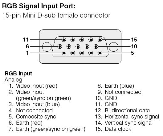
59 Connectors
60
61
62
63 Serial mouse Pin Description 1 DCD Data carried detect 2 RD Receive data 3 TD Transmit data 4 DTR Data terminal ready 5 SG Signal ground 6 DSR Data set ready 7 RTS Request to send 8 CTS Clear to send 9 Ring
64 Image Dimensions in Common Usage Collated by Paul Bourke May 2000 Dimensions Ratio Comments 8x8 1 16x16 1 Macintosh cursor size Supported by Windows icon format 32x32 1 Macintosh icon size Supported by Windows icon format 64x64 1 Supported by Windows icon format 88x WWW micro banner 128x96 1 1/3 160x /3 NTSC 13" 1/16th CuSeeMe small image size Considered a "small" QuickTime movie 160x x x x /3 192x /3 PAL 1/16 234x WWW small banner 256x /3 10"/12" 1/4 320x Called CGA, IBM PS/2 320x /3 NTSC 13" 1/4 CuSeeMe image size Considered a "large" QuickTime movie 320x x Amigo
65 352x PAL Video CD 352x NTSC Video CD 384x Photo CD 384x /3 PAL 1/4 392x WWW banner 400x /3 460x WWW banner 468x WWW banner 468x WWW banner 512x Original Macintosh screen 512x /3 544x WebTV image size 640x Called EGA, IBM 640x /3 NTSC full Called PGA, IBM VGA 640x x Full image size from ASUS video capture with TNT2 720x Called MDA, IBM / VESA 720x Called MCGA, IBM/VESA 720x Format 480p. NTSC video format as used by DPS PVR video hardware. NTSC DV SDTV 720x SDTV 720x Alternative Media-100 NTSC, eg: Media x486 40/27 CCIR 601 NTSC 720x /3 CCIR 601 NTSC Sq 720x CCIR 601 DV PAL and DV SECAM
66 729x Hercules graphics 768x576 Subtract 75 from left/right and 55 top/bottom for the PAL "safe" area 1 1/3 CCIR 601 PAL full 800x /3 Called SVGA resolution. Used in the first generation of LCD projectors (their native resolution). 832x /3 Macintosh 856x x x /3 Non standard digital TV format supported by some suppliers. 1024x /3 XGA. Native resolution of many LCD projectors. Used by VisionStation and VisionStation x HDTV 1152x x /3 VESA 1152x Macintosh 1152x Sun / SGI 1280x720 16/9 Format 720p. HDTV WXGA 1280x x Mac G4 15" laptop 1280x /3 SXVGA 1280x Optimised on the PowerStorm 350 OpenGL card/drivers from Compaq 1280x SXGA 1360x
67 1365x768 16:9 (nearly, ) NEC 61" plasma 1365x /3 VisionStation 3 with upgrade and VisionStation x DELL Laptop 1440x Apple 17" G4 laptop 1520x x900 16:9 1600x x /3 VESA UXGA 1792x x /3 1824x x /3 1856x /3 1920x /9 1080i format. HDTV, known as 1K 1920x x /3 2000x QXGA 2048x :9 2048x /3 Feature film, known as 2K Also used by DOME display controllers 2048x Tiger high resolution display 2500x x Sometimes used for IMAX (?) 3600x Sometimes used for IMAX (?) 4096x /3 Image size for IMAX 3D rendering, known as 4K 4096x NCSA tiled wall (2001)
68 Serial Mouse Data Formats The Microsoft Serial Mouse format is the defacto standard for serial mice. The Microsoft mouse format allows for only two buttons. Three button mice working in Microsoft mode ignore the middle button. The data packets are sent at 1200 baud with 1 stop bit and no parity. Each packet consists of 3 bytes. It is sent to the computer every time the mouse changes state (ie. the mouse is moved or the buttons are pressed/released). D6 D5 D4 D3 D2 D1 D st byte 1 LB RB Y7 Y6 X7 X6 2nd byte 0 X5 X4 X3 X2 X1 X0 3rd byte 0 Y5 Y4 Y3 Y2 Y1 Y0 LB is the state of the left button, 1 = pressed, 0 = released. RB is the state of the right button, 1 = pressed, 0 = released X0-7 is movement of the mouse in the X direction since the last packet. Positive movement is toward the right. Y0-7 is movement of the mouse in the Y direction since the last packet. Positive movement is back, toward the user. The mouse driver software collects the X and Y movement bits from the different bytes in the packet. All moves are sent as two s complement binary numbers. Although the Microsoft format only requires 7 data bits per byte, most mice actually send 8-bit data with the most significant bit set to 1. Since the most-significant-bit (D7) is last in the serial data stream, this is the same as sending two stop bits instead of one. The Joymouse sends data packets as shown below. D7 D6 D5 D4 D3 D2 D1 D st byte 1 1 LB RB Y7 Y6 X7 X6 2nd byte 1 0 X5 X4 X3 X2 X1 X0 3rd byte 1 0 Y5 Y4 Y3 Y2 Y1 Y0 [ Back to Data & Documentation ] [ Home ]

69 Next: Motorola 68HC11 SCI Interface Up: Serial Communication Previous: Asynchronous Serial Communication (SCI) RS-232 Serial Protocol The RS-232 serial communication protocol is a standard protocol used in asynchronous serial communication. It is the primary protocol used over modem lines. It is the protocol used by the MicroStamp11 when it communicates with a host PC. Figure 23 shows the relationship between the various components in a serial ink. These components are the UART, the serial channel, and the interface logic. An interface chip known as the universal asynchronous receiver/transmitter or UART is used to implement serial data transmission. The UART sits between the host computer and the serial channel. The serial channel is the collection of wires over which the bits are transmitted. The output from the UART is a standard TTL/CMOS logic level of 0 or 5 volts. In order to improve bandwidth, remove noise, and increase range, this TTL logical level is converted to an RS-232 logic level of or volts before being sent out on the serial channel. This conversion is done by the interface logic shown in figure 23. In your system the interface logic is implemented by the comm stamp. Figure 23: Asynchronous (RS-232) serial link A frame is a complete and nondivisible packet of bits. A frame includes both information (e.g., data and characters) and overhead (e.g., start bit, error checking and stop bits). In asynchronous serial protocols such as RS-232, the frame consists of one start bit, seven or eight data bits, parity bits, and stop bits. A timing diagram for an RS-232 frame consisting of one start bit, 7 data bits, one parity bits and two stop bits is shown below in figure 24. Note that the exact structure of the frame must be agreed upon by both transmitter and receiver before the comm-link must be opened. Figure 24: RS-232 Frame (1 start bit, 7 data bits, 1 parity bits,
70 and 2 stop bits) Most of the bits in a frame are self-explanatory. The start bit is used to signal the beginning of a frame and the stop bit is used to signal the end of a frame. The only bit that probably needs a bit of explanation is the parity bit. Parity is used to detect transmission errors. For even parity checking, the number of 1 s in the data plus the parity bit must equal an even number. For odd parity, this sum must be an odd number. Parity bits are used to detect errors in transmitted data. Before sending out a frame, the transmitter sets the parity bit so that the frame has either even or odd parity. The receiver and transmitter have already agreed upon which type of parity check (even or odd) is being used. When the frame is received, then the receiver checks the parity of the received frame. If the parity is wrong, then the receiver knows an error occurred in transmission and the receiver can request that the transmitter re-send the frame. In cases where the probability of error is extremely small, then it is customary to ignore the parity bit. For communication between the MicroStamp11 and the host computer, this is usually the case and so we ignore the parity bit. The bit time is the basic unit of time used in serial communication. It is the time between each bit. The transmitter outputs a bit, waits one bit time and then outputs the next bit. The start bit is used to synchronize the transmitter and receiver. After the receiver senses the true-false transition in the start bit, it waits one half bit time and then starts reading the serial line once every bit time after that. The baud rate is the total number of bits (information, overhead, and idle) per time that is transmitted over the serial link. So we can compute the baud rate as the reciprocal of the bit time. Next: Motorola 68HC11 SCI Interface Up: Serial Communication Previous: Asynchronous Serial Communication (SCI) Bill Goodwine

71 Next: LCD display for the Up: Serial Communication Previous: RS-232 Serial Protocol Motorola 68HC11 SCI Interface The Motorola 68HC11 supports one SCI. We ll discuss both transmitting and receiving ends of the SCI. The programmer controls the operation of the SCI interface through a set of hardware registers that are memory mapped into the processor s address space. There are 5 control registers shown below in figure 25. This figure also shows the logical names for individual bits in the registers. The BAUD register is used to set the serial link s baud rate. There are two control registers SCCR1 and SCCR2 that specify how the SCI should work. There is a status register, SCSR that the programmer can use to check whether the transmission/reception of a frame has been completed. Finally there is the data register SCDR that holds the transmitted or received information bits. Figure 25: 68HC11 SCI Registers From the number of control bits in the SCCR1 and SCCR2 registers you can see that the programmer has quite a bit of control over the SCI interface. Most of the situations we ll be using, however, have standard set-ups so we won t need to discuss the control register bits in detail. Instead, we ll provide standard functions that encapsulate the user s interface to SCI devices such as a personal computers and simply discuss how these functions work. The proper setup of the SCI subsystem is usually done in your program s init() initialization routine. To understand how the SCI subsystem works, let s examine figure 26. Figure 26 shows how the programmer interacts with the SCI transmit and receive buffers. In order to transmit, the programmer first loads the 8-bit data register SCDR with the data to be sent. The SCI module automatically fills in the start bit, stop bit, and the extra T8 bit from control register SCCR1. The T8 bit can be used as a parity bit.

72 Once the SCDR register is loaded, the subsystem loads this data into the SCI module s transmit buffer. The SCI transmit buffer then holds a single frame and this frame is then clocked out of the transmit register one bit at a time at the rate specified in the BAUD register. Once all of the bits have been clocked out of the transmit buffer, the SCI module sets the TDRE (transmit data register empty) bit in the SCI s status register SCSR. This single bit can then be used to check whether or not the frame has been successfully transmitted. Figure 26: SCI transmit and receive buffers A similar set of steps can be used to check and see if the receive data register has been filled. Once initialized, the receive data component of the SCI subsystem will wait for the true-to-false transition on the input line signalling a start bit. After the start bit has been detected, the receive subsystem will shift in 10 or 11 bits into the receive data register. The start and stop bits are removed and 8 bits of data are loaded into the SCI data register SCDR. The ninth parity bit R8 is put in the SCCR1 control register. When the receive data register is full, then the SCI subsystem sets the RDRF (receive data register full) flag in the status register SCSR. The programmer can then check this status flag to see if a full frame has been received. The following code segment from an init() function can be used to initialize the SCI module to transmit and receive at 38 kbaud. This setup was used in our earlier kernel.c functions to send characters back and forth between the MicroStamp11 and the PC. void init(void){ asm(" sei"); CONFIG = 0x04; BAUD=BAUD38K; SCCR1 = 0x00; SCCR2 = 0x0C; asm(" cli"); } The instructions in this function do the following. The first instruction CONFIG = 0x04 turns off the
Sender Receiver Sender
 EEE 410 Microprocessors I Spring 04/05 Lecture Notes # 19 Outline of the Lecture Interfacing the Serial Port Basics of Serial Communication Asynchronous Data Communication and Data Framing RS232 and other
Serial Interfaces Part 1. ECE 153B Sensor & Peripheral Interface Design Winter 2016
 Serial Interfaces Part 1 ECE 153B Sensor & Peripheral Interface Design Serial Interfaces Simple Serial Interfaces RS-232C (UART) Provides for point to point communications, primarily Among the simplest
Table 8 shows the pin configuration and function of a standard computer-to-printer parallel cable. Table 8 Parallel Cable Pin Configuration
 Advanced Printer Inion Parallel Data Port Parallel Data Port The parallel data interface supports IEEE 1 bidirectional parallel communications in nibble mode. The parallel interface provides a means of
Select a Data Communication Interface
 Printer Setup and Operation Select a Data Communication Interface Select a Data Communication Interface You may connect your print engine to a computer using one or more of the available connections. The
Integrity Instruments Application Notes. Release 1
 Integrity Instruments Application Notes Release 1 What is EIA/TIA/RS-485 What is EIA/TIA/RS-422 Half Duplex and Full Duplex Communication Asynchronous Communicatin Grounding EIA/TIA/RS-485/422 Shielding
4.3 Digital Communication
 Data Acquisition & Computer Control 11 4.3 Digital Communication Why digital communication (often termed digital input/output, or DIO)? Because the language of computers (and many peripheral devices) is
Chapter 11: Input/Output Organisation. Lesson 05: Asynchronous RS232C Serial Port data transfer
 Chapter 11: Input/Output Organisation Lesson 05: Asynchronous RS232C Serial Port data transfer Objective Understand the RS232C asynchronous data transfer and signals Learn the RS232C serial port communication
SC32A Optically Isolated RS232 Interface
 SC32A Optically Isolated RS232 Interface Reference Manual Issued 5.5.94 Copyright 1987 Campbell Scientific Inc. Copied under licence by Campbell Scientific Ltd. Guarantee This equipment is guaranteed
8051SERIAL PORT PROGRAMMING
 8051SERIAL PORT PROGRAMMING Basics of Serial Communication Computers transfer data in two ways: Parallel Often 8 or more lines (wire conductors) are used to transfer data to a device that is only a few
Serial Communication Prof. James L. Frankel Harvard University. Version of 2:30 PM 6-Oct-2015 Copyright 2015 James L. Frankel. All rights reserved.
 Serial Communication Prof. James L. Frankel Harvard University Version of 2:30 PM 6-Oct-2015 Copyright 2015 James L. Frankel. All rights reserved. Overview of the Serial Protocol Simple protocol for communicating
Manual Industry Interfaces
 Manual Industry Interfaces W&T Release. Type 0, 0 0, 00 0, 0 0, 0 Industry Interfaces 0/0 by Wiesemann & Theis GmbH Subject to errors and changes: Since we can make mistakes, none of our statements should
Macintosh Serial Port Connections. David P. Goldenberg December Introduction. 1.1 Disclaimer First Steps References...
 Macintosh Serial Port Connections David P. Goldenberg December 00 Contents Introduction. Disclaimer...................................... First Steps...................................... References.....................................
ANC Series RS-422 Serial Communications Adapter
 Rev. B $ 5.00 ANC - 6000 Series RS-422 Serial Communications Adapter Antona Corporation, Los Angeles, CA Antona Corporation (818)783-4299 FAX (818)783-4216 1 Antona Corporation Copyright Copyright (c)
Advanced Electronic Communications Systems Wayne Tomasi Sixth Edition
 Advanced Electronic Communications Systems Wayne Tomasi Sixth Edition Pearson Education Limited Edinburgh Gate Harlow Essex CM20 2JE England and Associated Companies throughout the world Visit us on the
Lecture-65 SERIAL DATA COMMMUNICATION The data bus of a microcomputer system is designed to transfer data to and from I/O device in parallel - all
 Lecture-65 SERIAL DATA COMMMUNICATION The data bus of a microcomputer system is designed to transfer data to and from I/O device in parallel - all bits of a data word are transformed simultaneously. This
Course 10: Interfaces Agenda
 Course 10: Interfaces 1 Agenda Introduction V.24 interface (RS232) USB 2 Introduction 3 Definition(s) (from the web) A boundary across which two independent systems meet and act on or communicate with
SC32A OPTICALLY ISOLATED RS232 INTERFACE INSTRUCTION MANUAL
 SC32A OPTICALLY ISOLATED RS232 INTERFACE INSTRUCTION MANUAL REVISION: 1/93 COPYRIGHT (c) 1987, 1993 CAMPBELL SCIENTIFIC, INC. WARRANTY AND ASSISTANCE The SC32A OPTICALLY ISOLATED RS232 INTERFACE is warranted
e-pg Pathshala Subject : Computer Science Paper: Embedded System Module: Serial Port Communication Module No: CS/ES/11 Quadrant 1 e-text
 e-pg Pathshala Subject : Computer Science Paper: Embedded System Module: Serial Port Communication Module No: CS/ES/11 Quadrant 1 e-text In this lecture, serial port communication will be discussed in
Product Manual. USB to Optical Adapter Industrial Isolated RS- 232/422/485. Coolgear, Inc. Version 2.1 December 2018 Model Number: USB-COMi-Si-M
 USB to Optical Adapter Industrial Isolated RS- 232/422/485 Product Manual Coolgear, Inc. Version 2.1 December 2018 Model Number: USB-COMi-Si-M 2 USB-COMi-SI-M Product Manual Revision History Revision Date
Serial Interfacing. Asynchronous Frame
 Serial Interfacing Serial Data Transfer used by keyboards, plotters, modems and other peripherals with low data transfer rates (low bandwidth) 2 Types: Asynchronous CPU and device are not using a common
AB300-Series Automated Filter Wheels
 AB300-Series Automated Filter Wheels User Manual 1049478 August 2006 1. Introduction 1.1 Mission Statement Our mission is to provide our customers with reliable products, on time, and at a fair price.
Wrenchman, Inc Old Hwy. # 8 Suite # 122 New Brighton, Minnesota (651)
") Wrenchman, Inc. 1801 Old Hwy. # 8 Suite # 122 New Brighton, Minnesota 55112 (651) 638-9012 468X Interface Cable Specifications The Interface Cable emulates the Async RS-232 logical interface supported
Wrenchman, Inc. 1801 Old Hwy. # 8 Suite # 122 New Brighton, Minnesota 55112 (651) 638-9012 468X Interface Cable Specifications The Interface Cable emulates the Async RS-232 logical interface supported
The Wireless Connectivity Expert
 The Wireless Connectivity Expert 48511 Warm Springs Blvd., Suite 206, Fremont CA 94539 Tel: (510) 490-8024 Fax: (510) 623-7268 Website: http://www.actisys.com/ E-mail: irda-info@actisys.com ACT-IR100SD
MEV Limited USB232/485 INSTRUCTION MANUAL
 MEV Limited USB232/485 INSTRUCTION MANUAL USB TO RS232 / RS485 SERIAL COMMUNICATIONS INTERFACE WITH ISOLATION OPTION Issue 5 LIST OF CONTENTS 1 INTRODUCTION 1 1.1 The Products Described in this Manual
CMM 900-3W USER GUIDE
 CMM 900-3W USER GUIDE AMPS Cellular Modem Module (3W) Page 1 of 1 Table of Contents 1. PRODUCT OVERVIEW...3 1.1 Features:... 3 1.2 Serial Port Pins:... 5 1.3 Applications:... 5 1.4 Your package includes:...
Hardware Manual. PCMCIA 1 Port RS EDITION APRIL 1999
 Hardware Manual 232 232232 PCMCIA 1 Port RS232 1.1 EDITION APRIL 1999 Guarantee. FULL 36 MONTHS GUARANTEE. We guarantee your interface card for a full 36 months from purchase, parts and labour, provided
Building the Communication Cable
 uilding the Communication Cable 99 uilding the Communication Cable There are several considerations that help determine the type of cable needed for your application. 1. Will the be physically connected
ICP PANEL-TEC PEX3000 II
 ICP PANEL-TEC PEX3000 II MODBUS PORT EXPANDER INSTALLATION AND OPERATION GUIDE REVISION HISTORY Revision Date Author Comments 000 29 Aug 2008 Keira Majors Initial release. 001 16 Sep 2008 David Walker
HomeVision-Serial. Add-On Card. Installation and Operation Manual
 Serial Add-On Card Installation and Operation Manual Custom Solutions, Inc. P.O. Box 33905 Indialantic, FL 32903 E-mail: csi@csi3.com Internet: www.csi3.com Serial (Version II) INTRODUCTION Serial is
RS-232 DATA COMMUNICATIONS WITH THE TANDY COLOR COMPUTER
 By Tom Gunnison 1998 DISCLAIMER These plans and software are provided "as is" with no guarantee of fitness for the purpose either explicit or implied. I disclaim any responsibility for losses incurred
PCL Port RS-232 Interface Card
 PCL-858 8-Port RS-232 Interface Card Copyright Notice This documentation and the software included with this product are copyrighted 2001 by Advantech Co., Ltd. All rights are reserved. Advantech Co.,
Appendix A Cable Pinouts
 Appendix A Cable Pinouts This appendix lists the cables and connector pinout assignments for the cables used with the ERX-7xx models and ERX-14xx models. Topic Page SRP I/O Module 163 CT1 and CE1 I/O Modules
User s Manual ANC-6023 RS232/RS422/Video Sync Interface Adapter
 Rev A User s Manual ANC-6023 RS232/RS422/Video Sync Interface Adapter 1 Copyright Copyright 2006-2015 by Antona Corporation. All rights reserved. No part of this publication may be transmitted, transcribed,
Copyright Black Box Corporation. All rights reserved.
 Copyright 1998. Black Box Corporation. All rights reserved. 1000 Park Drive Lawrence, PA 150551018 7247465500 Fax 7247460746 SAM232 Compact MARCH 1998 TS158A DB 9P cable test 1 5 6 8 7 2 3 9 4 7 6 5 4
EWAVE Inc Gracefield Ln. Dallas, Texas (972)
") EWAVE Inc. 7419 Gracefield Ln. Dallas, Texas 75248 (972) 248-2931 www.electrowave.com STAMPER User s Manual Version 1.0 Ewave Radio Modems covered in this manual: STAMPER INTRODUCTION... 3 1.1 FEATURES
EWAVE Inc. 7419 Gracefield Ln. Dallas, Texas 75248 (972) 248-2931 www.electrowave.com STAMPER User s Manual Version 1.0 Ewave Radio Modems covered in this manual: STAMPER INTRODUCTION... 3 1.1 FEATURES
You want to learn about point to point asynchronous serial links and how to apply them in practice. You want to learn how to link RS-232C devices
 143 Chapter 5 Serial Data Communications - Hardware Application A Summary... Asynchronous communications techniques. The RS-232C System. Definitions and shortcomings. How to physically link devices on
3710 ACM 3750 PDC 3800 RTU. ISOCOM Communications Card Retrofit Instructions
 3710 ACM 3750 PDC 3800 RTU ISOCOM Communications Card Retrofit Instructions Danger During normal operation of this device, hazardous voltages are present which can cause severe injury or death. These
WTDIO-M. eeder. Digital I/O Module. Technologies FEATURES SPECIFICATIONS DESCRIPTION. Weeder Technologies
 eeder Technologies 90-A Beal Pkwy NW, Fort Walton Beach, FL 32548 www.weedtech.com 850-863-5723 Digital I/O Module FEATURES 14 I/O channels; individually configured for input or output. All inputs incorporate
Cable Pinouts. SRP I/O Module
 Cable Pinouts A This appendix lists the cables and connector pinout assignments for the cables used with the ERX-7xx models and ERX-14xx models. Topic Page SRP I/O Module A-1 CT1 and CE1 I/O Modules A-4
Connector and Cable Specifications
 APPENDIX B This appendix describes the pinouts and cabling requirements for the interfaces and cables used on the Cisco ubr925 cable access router. All connectors for these interfaces are on the rear-panel,
Serial I/O. 4: Serial I/O. CET360 Microprocessor Engineering. J. Sumey
 4: Serial I/O CET360 Microprocessor Engineering J. Sumey Introduction serial, i.e. bit-at-a-time, interfacing techniques are useful when parallel interfacing limitations become problematic distance limitations
ME930C-RJ11 MAIN MODULE (FRONT CARD) MAIN MODULE. Line: RJ-11 INTERFACE MODULE (REAR CARD) Serial: DB25 CONN. SW1 RJ-11 CONN.
 MAIN MODULE. Line: RJ-11 INTERFACE MODULE (REAR CARD) Serial: DB25 CONN. SW1 RJ-11 CONN.") ME930C-RJ11 Line: RJ-11 ME930C-RJ11 MAIN MODULE Power -TD -RD INTERFACE MODULE (REAR CARD) TEST -Cntrl In -Cntrl Out Serial: DB25 CN. 7 8 SW1 JB2 1 2 3 RJ-11 CN. JB3 INTERFACE MODULE (REAR CARD) 1 2 3
ME930C-RJ11 Line: RJ-11 ME930C-RJ11 MAIN MODULE Power -TD -RD INTERFACE MODULE (REAR CARD) TEST -Cntrl In -Cntrl Out Serial: DB25 CN. 7 8 SW1 JB2 1 2 3 RJ-11 CN. JB3 INTERFACE MODULE (REAR CARD) 1 2 3
Advantages and disadvantages
 Advantages and disadvantages Advantages Disadvantages Asynchronous transmission Simple, doesn't require synchronization of both communication sides Cheap, timing is not as critical as for synchronous transmission,
SyncLink GT2E/GT4E Serial Adapter
 SyncLink GT2E/GT4E Serial Adapter Hardware User s Manual MicroGate Systems, Ltd http://www.microgate.com MicroGate and SyncLink are registered trademarks of MicroGate Systems, Ltd. Copyright 2008-2017
General Specifications. P2-SCM Serial Communications
 General Specifications Module Type Intelligent Modules per Base I/O Points Used Field Wiring Connector Operating Temperature Storage Temperature Humidity Environmental Air Vibration Shock Field to Logic
CS485. User s Manual. Version ZYPEX, Inc.
 CS485 User s Manual Version 2.0 2003 ZYPEX, Inc. Table of Contents Product Description 1 CS485 Configuration & Setup 2 4-wire Operation 2 2-wire Operation 2 Dual Port Operation 2 Carrier Detect 2 Transmitter
SyncLink USB Serial Adapter
 SyncLink USB Serial Adapter Hardware User s Manual MicroGate Systems, Ltd http://www.microgate.com MicroGate and SyncLink are registered trademarks of MicroGate Systems, Ltd. Copyright 2012-2017 MicroGate
DATA CONNECT ENTERPRISE
 DATA CONNECT ENTERPRISE User s Manual IG202T and IGV23 Modem Document Number 520-01005-001 Rev. A DATA CONNECT Contents Contents... iii Figures... iv Chapter 1 Introduction... 5 Features...6 Applications...7
Automationdirect.com. D i r e c t L o g i c M O D B U S S L A V E F 4 S L V - M B
 Automationdirect.com D i r e c t L o g i c 4 0 5 M O D B U S S L A V E F 4 S L V - M B Order Number: F4-SLVMB-M Automationdirect.com is a Trademark of Automationdirect.com Modbus is a Trademark of Gould
MICROGATE SERIAL COMMUNICATIONS RUN TIME KIT WINDOWS GUIDE
 MICROGATE SERIAL COMMUNICATIONS RUN TIME KIT WINDOWS GUIDE MicroGate Systems, Ltd http://www.microgate.com MicroGate and SyncLink are registered trademarks of MicroGate Systems, Ltd. Copyright 2012-2016
RS-232 Fiber Link Card System
 USER GUIDE The leader in rugged fiber optic technology. U-152 2018B-0406 Fiber Link Card System SYSTEM INSTALLATION INFORMATION Introduction The Fiber Link Card system transports a full 9-Pin copper signal
W&T Manual Interface modules W&T
 Manual Subject to error and alteration Model 18801, 18811 18802, 18812 18803, 18813, 18833 18601, 18611 18602, 18612 18613, 18633 18401, 18411 18402, 18412 Release 1.7 43 09/2013 by Wiesemann und Theis
AN_2901_005 JULY The Teridian 73M2901CE single chip modem implements the V.23 standard according the ITU V.23 recommendation.
 73M2901CE V.22 bis Single Chip Modem A Maxim Integrated Products Brand APPLICATION NOTE AN_2901_005 JULY 2005 1 ITU V.23 Recommendation The Teridian 73M2901CE single chip modem implements the V.23 standard
ExpressCard Serial Adapters User s Manual SSPXP-100 DSPXP-100 QSPXP-100 SSPXP-200/300 DSPXP-200/300 QSPXP-200/300
 ExpressCard Serial Adapters User s Manual SSPXP-100 DSPXP-100 QSPXP-100 SSPXP-200/300 DSPXP-200/300 QSPXP-200/300 SSPXP/DSPXP/QSPXP-100/200/300 User s Manual P/N: 940-5000-100G Rev. 1.00 July 2007 International
Bell System Data Communications TECHNICAL REFERENCE 411 Y DATA SET 113A INTERFACE SPECIFICATION MAY 1969
 Bell System Data Communications TECHNICAL REFERENCE.. l j 411 Y DATA SET 113A INTERFACE SPECIFICATION MAY 1969 Bell System Data Communications TECHNICAL REFERENCE Data Set 113A Interface Specifications
RS-232 is a complete standard. This means that the standard sets out to ensure compatibility between the host and peripheral systems by specifying:
 Maxim > App Notes > INTERFACE CIRCUITS Keywords: RS-232, rs232, EIA-RS232, EIA/TIA-232-E Mar 29, 2001 APPLICATION NOTE 83 Fundamentals of RS-232 Serial Communications Abstract: Due to its relative simplicity
UNIT-V COMMUNICATION INTERFACE
 UNIT-V COMMUNICATION INTERFACE SERIAL DATA TRANSFER INTRODUCTION Data transmission, digital transmission or digital communications is the physical transfer of data (a digital bit stream) over a point-to-point
Serial Communication Converters & Adapters Instruction Manual
 Serial Communication Converters & Adapters Instruction Manual RS-232 to RS-422/485 Converter Isolated RS-232 to RS-422/485 Converter USB to RS-232 Converter USB to RS-422/485 Converter Isolated USB to
RS-232 Connector Pin Assignments
 APPENDIXB This appendix lists the connector pin assignments for the CDEs, and includes the following sections: Serial Console-Interface, page B- Ethernet, page B- Cable Pin Assignments, page B- Serial
RS-232 Industrial Media Converter
 USER GUIDE The leader in rugged fiber optic technology. U-151 2018C-0327 Industrial Media Converter COMPACT, RUGGED & TEMPERATURE HARDENED Introduction This Industrial Serial Data media converter transports
Chapter 7: Data Link Control. CS420/520 Axel Krings Page 1
 Chapter 7: Data Link Control CS420/520 Axel Krings Page 1 Data Link Control Protocols Need layer of logic above Physical to manage exchange of data over a link frame synchronization flow control error
IM3523 IM3533 IM IM3536 LCR METER IM3570 IM7580 IM3590 CHEMICAL IMPEDANCE ANALYZER IMPEDANCE ANALYZER. Communication Instruction Manual
 Communication Instruction Manual IM3523 IM3533 IM3533-01 IM3536 LCR METER IM3570 IM7580 IMPEDANCE ANALYZER IM3590 CHEMICAL IMPEDANCE ANALYZER November 2014 Revised edition 6 IM3570A983-06 14-11H i Contents
Chapter 7: Data Link Control. Data Link Control Protocols
 Chapter 7: Data Link Control CS420/520 Axel Krings Page 1 Data Link Control Protocols Need layer of logic above Physical to manage exchange of data over a link frame synchronization flow control error
WTDIO-M. e e d e r. Digital I/O Module. Technologies FEATURES. Price $59 SPECIFICATIONS DESCRIPTION. Weeder Technologies
 e e d e r Technologies 90-A Beal Pkwy NW, Fort Walton Beach, FL 32548 www.weedtech.com Voice/Fax 850-863-5723 Digital I/O Module FEATURES 14 I/O channels; individually configured for input or output. All
RCS/6000. Hardware. Manual
 RCS/6000 Hardware Manual Document number 80-001052-6 Revision A RCS/6000 Hardware Manual Document part number 80-001052-6 Revision History Date Revision Description 4/10/01 A Initial production release
Storage/Control I/O Module
 CHAPTER 4 The performs two functions: to connect outside interfaces to the system controller and to house the hard disk drive. It plugs into the back of the VCO/4K system and provides the I/O interfaces
AD-8923-BCD. Remote Controller (BCD) INSTRUCTION MANUAL 1WMPD
 INSTRUCTION MANUAL 1WMPD") AD-8923-BCD Remote Controller (BCD) INSTRUCTION MANUAL 1WMPD4002137 2010 A&D Company, Limited. All rights reserved. No part of this publication may be reproduced, transmitted, transcribed, or translated
AD-8923-BCD Remote Controller (BCD) INSTRUCTION MANUAL 1WMPD4002137 2010 A&D Company, Limited. All rights reserved. No part of this publication may be reproduced, transmitted, transcribed, or translated
ZM24x Quick-Connect Industrial Modem. User s Manual
 ZM24x Quick-Connect Industrial Modem User s Manual Version 1.1 2004 ZYPEX, Inc. All Rights Reserved 1 ZM24x Quick-Connect Industrial Modem Since the equipment explained in this manual has a variety of
USER MANUAL. MODEL 1018 High Speed Short Range Modem w/ Extra Controls SALES OFFICE (301) TECHNICAL SUPPORT (301)
 TECHNICAL SUPPORT (301)") USER MANUAL MODEL 1018 High Speed Short Range Modem w/ Extra Controls Part# 07M1018-B Doc# 013021UB Revised 11/3/95 SALES OFFICE (301) 975-1000 TECHNICAL SUPPORT (301) 975-1007 1.0 WARRANTY INFORMATION
USER MANUAL MODEL 1018 High Speed Short Range Modem w/ Extra Controls Part# 07M1018-B Doc# 013021UB Revised 11/3/95 SALES OFFICE (301) 975-1000 TECHNICAL SUPPORT (301) 975-1007 1.0 WARRANTY INFORMATION
Bluetooth to RS-232&RS422/485. EX-9132B/BI Bluetooth Adapter Operation Manual
 Bluetooth to RS-232&RS422/485 EX-9132B/BI Bluetooth Adapter Operation Manual First Edition, Jun 2008 Table of Contents 1. Introduction 2 2. Package checklist 3 3. Product Specification 4 4. Product Panel
Data Communications & Computer Networks. Digital Data Communications Techniques
 Data Communications & Computer Networks Chapter 6 Digital Data Communications Techniques Fall 2008 Agenda Preface Asynchronous & Synchronous transmission Error Detection & Correction Line configurations
Connector and Cable Specifications
 APPENDIX B This section describes the Catalyst 4224 Access Gateway Switch ports and the cables and adapters used to connect the switch to other devices. This section includes the following topics: Console
Hardware Manual PCMCIA DUAL RS EDITION MAY 1999
 Hardware Manual 232 232232 PCMCIA DUAL RS232 1.4 EDITION MAY 1999 Guarantee. FULL 36 MONTHS GUARANTEE. We guarantee your interface card for a full 36 months from purchase, parts and labour, provided it
RS-232 SERIAL INTERFACE PHOTOELECTRIC ISOLATOR
 RS-232 SERIAL INTERFACE PHOTOELECTRIC ISOLATOR User Manual DA-70163 I. Summary With adoption of advanced photoelectric isolation technology, RS-232 Serial Interface Photoelectric Isolator, also named Serial
QuVIS CONNECTOR PINOUT GUIDE
 QuVIS CONNECTOR PINOUT GUIDE The following sections describe the rear panel connector pinouts. Analog Audio/LTC timecode breakout cable AES Digital Audio connector (rear panel) GPI I/O connector RS-422
Serial Interfacing. Pulse width of 1 bit
 ١ ٢ Asynchronous Frame 10 bits 7E1 (7 data bits, even parity, 1 stop bit) Serial Data Transfer used by keyboards, plotters, modems and other peripherals with low data transfer rates (low bandwidth) * *
EIA530, RS232, V.35 Interface For OM200 SONET-OC3 Multiplexer
 OM00- / (serial data) EIA0, RS, V. Interface For OM00 SONET-OC Multiplexer Chassis Chassis sizes of,,, and 1 slot. Optical data rate of 1Mbps Single or multimode fiber versions Point-to-point topology
Four opto-isolated signal channels: SD, RD, RTS, and CTS. Electrical compatibility with RS-485. A 5V DC/DC converter for power isolation
 July 2000 RS-4 Port Isolator IC0ACC03 The IC0ACC03 RS-4 Port Isolator replaces the obsolete ICCMM0 Isolated Repeater/Converter (also known as the Brick ). This Port Isolator provides the basic functionality
Miniature Asynchronous 4-Wire High Speed Modems
 ME1862A-F ME1863A-F JULY 2003 ME1862A-M ME1863A-M Miniature Asynchronous 4-Wire High Speed Modems CUSTOMER SUPPORT INFORMATION Order toll-free in the U.S.: Call 877-877-BBOX (outside U.S. call 724-746-5500)
11 Serial Communications
 11.1 COMMUNICATIONS PACKAGES There are a number of communication packages that can be used with the Quantum III to facilitate setup, record parameter data, view internal activity on a soft-scope and permit
SyncLink GT Serial Adapter
 SyncLink GT Serial Adapter Hardware User s Manual MicroGate Systems, Ltd http://www.microgate.com MicroGate and SyncLink are registered trademarks of MicroGate Systems, Ltd. Copyright 2008-2017 MicroGate
Cable Specifications. Interface Specifications. Fiber-Optic Specifications APPENDIXB
 APPENDIXB This appendix lists the cable specifications for supported modules on the Cisco 7600 series router. The following signal summaries are contained in this appendix: Interface Specifications, page
CONNECT WITH RELIABILITY. USB-to-Serial Adapter User s Manual
 CONNECT WITH RELIABILITY USB-to-Serial Adapter User s Manual SSU2/DSU2/QSU2/ESU2-100/400 1-, 2-, 4-, and 8 serial ports QUATECH, INC. 5675 Hudson Industrial Parkway Hudson, Ohio 44236-5012 Toll free: 1-800-553-1170
PPP. Point-to-Point Protocol
 PPP Point-to-Point Protocol 1 Introduction One of the most common types of WAN connection is the point-to-point connection. Point-to-point connections are used to connect LANs to service provider WANs,
EZL-200F Application Notes (003) Serial Interface (RS232/RS422/RS485)
 Serial Interface (RS232/RS422/RS485)") Application Notes (003) Serial Interface (RS232/RS422/RS485) Version 2.0 Sollae Systems Co., Ltd. 1. Overview supports three serial interfaces: RS232, RS422, and RS485. You can select the interface you
Application Notes (003) Serial Interface (RS232/RS422/RS485) Version 2.0 Sollae Systems Co., Ltd. 1. Overview supports three serial interfaces: RS232, RS422, and RS485. You can select the interface you
ANC6185R. RS-485/422 Serial Communications Adapter. Antona Corporation, Los Angeles, CA
 Rev. C $ 5.00 ANC - 6185 RS-485/422 Serial Communications Adapter Antona Corporation, Los Angeles, CA ANC-6185T ANC6185R Antona Corporation i (818)783-4299 Antona Corporation Copyright Copyright (c) 2003-2015
TABLE OF CONTENTS. Communication Functions
 TABLE OF CONTENTS Chapter 1: Chapter 2: Chapter 3: Chapter 4: General Features....................................................... 1-1 Functions......................................................
ZM56 High-Speed Industrial Modem. Command Summary. 1 ZM56 High-Speed Industrial Modem
 ZM56 High-Speed Industrial Modem Command Summary 1 ZM56 High-Speed Industrial Modem AT Command Summary Command AT ATA ATDT ATE0 ATE1 ATH ATH1 ATI ATO ATS Description Attention Prefix Precedes all commands
User Manual. ASeries A704
 User Manual ASeries A0 MultiPort Converter Serial & Parallel Parallel The interfacing specialists Version 1.00 March 1999 COPYRIGHTS All rights reserved. This document may not, in whole or part, be copied,
STEP X - Name of Step QUICK START GUIDE SP385A-R3, SP390A-R3 USB TO RS CONVERTER 24/7 TECHNICAL SUPPORT AT OR VISIT BLACKBOX.
 STEP X - Name of Step QUICK START GUIDE SP385A-R3, SP390A-R3 USB TO RS CONVERTER 24/7 TECHNICAL SUPPORT AT 877.877.2269 OR VISIT BLACKBOX.COM STEP 1 - Package Includes/System Requirements PACKAGE INCLUDES
TRAINING GUIDE LEVEL 3 MODBUS WRITE IMPORT COMMAND
 OleumTechTM TRAINING GUIDE LEVEL 3 MODBUS WRITE IMPORT COMMAND MUST BE FAMILIAR WITH LEVEL 1 TRAINING MATERIALS BEFORE MOVING FORWARD Doc ID# 80-6010-001b TABLE OF CONTENTS 1. WHAT IS NEW WRITE IMPORT
Appendix C. Datum Systems PSM-4900 Satellite Modem. Cabling Specifications
 DATUM SYSTEMS Appendix C Datum Systems PSM-4900 Satellite Modem Cabling Specifications PSM-4900 VSAT / SCPC - Cabling Specifications Revision History Rev 1.0 6-10-2000 Preliminary Release. Rev 1.1 8-1-2000
F2238A and F2245A Fiber-Optic EIA-530/MIL-STD Modem Technical Manual
 F2238A and F2245A Fiber-Optic EIA-530/MIL-STD-188-114 Modem Technical Manual Revision C October 2013 VERSITRON, Inc. 83 Albe Drive / Suite C Newark, DE 19702 www.versitron.com PROPRIETARY DATA All data
P3-SCM. General Specifications
 General Specifications Module Type Modules per Base Modules per Group I/O Points Used Field Wiring Connector Operating Temperature Storage Temperature Humidity Environmental Air Vibration Shock Field to
EECS 373 Design of Microprocessor-Based Systems
 EECS 373 Design of Microprocessor-Based Systems Prabal Dutta University of Michigan Lecture 10: Serial buses October 2, 2014 Some material from: Brehob, Le, Ramadas, Tikhonov & Mahal 1 Announcements Special
ME778C-RJ45 MAIN MODULE (FRONT CARD) MAIN MODULE. Line: RJ-45. Line: RJ-45 INTERFACE MODULE (REAR CARD) Serial: 10-Pin RJ.
 MAIN MODULE. Line: RJ-45. Line: RJ-45 INTERFACE MODULE (REAR CARD) Serial: 10-Pin RJ.") ME778C-RJ45 Line: RJ-45 MAIN MODULE Mini Driver MP Card ME778C-RJ45 Power Line: RJ-45 Unit A -TD -RD -CD -TD Serial: 10-Pin RJ INTERFACE MODULE (REAR CARD) Unit B -RD -CD Serial: 10-Pin RJ LO Z A HI Z
ME778C-RJ45 Line: RJ-45 MAIN MODULE Mini Driver MP Card ME778C-RJ45 Power Line: RJ-45 Unit A -TD -RD -CD -TD Serial: 10-Pin RJ INTERFACE MODULE (REAR CARD) Unit B -RD -CD Serial: 10-Pin RJ LO Z A HI Z
Revision: 5/7/ E Main Suite D Pullman, WA (509) Voice and Fax. Power jack 5-9VDC. Serial Port. Parallel Port
 Voice and Fax. Power jack 5-9VDC. Serial Port. Parallel Port") Digilent Digilab 2 Reference Manual www.digilentinc.com Revision: 5/7/02 215 E Main Suite D Pullman, WA 99163 (509) 334 6306 Voice and Fax Overview The Digilab 2 development board (the D2) features the
Digilent Digilab 2 Reference Manual www.digilentinc.com Revision: 5/7/02 215 E Main Suite D Pullman, WA 99163 (509) 334 6306 Voice and Fax Overview The Digilab 2 development board (the D2) features the
The Analyst. RS422/RS232 Tester. (Standard Model) User Manual
 User Manual") 12843 Foothill Blvd., Suite D Sylmar, CA 91342 818 898 3380 voice 818 898 3360 fax www.dnfcontrolscom The Analyst RS422/RS232 Tester (Standard Model) User Manual Manual Revision 102506 Table of Contents
12843 Foothill Blvd., Suite D Sylmar, CA 91342 818 898 3380 voice 818 898 3360 fax www.dnfcontrolscom The Analyst RS422/RS232 Tester (Standard Model) User Manual Manual Revision 102506 Table of Contents
Input-Output Organization
 Ted Borys - CSI 404 5/1/2004 Page 11-1 Section 11 Input-Output Organization ASCII Character Set 94 printable characters Upper & lowercase letters 10 numerals Special characters such as $, @, #, % 34 control
Digilab 2E Reference Manual
 Digilent 2E System Board Reference Manual www.digilentinc.com Revision: February 8, 2005 246 East Main Pullman, WA 99163 (509) 334 6306 Voice and Fax Digilab 2E Reference Manual Overview The Digilab 2E