Technical Description. Wired M-Bus. Water Meters flowiq 2101/3100
|
|
|
- Austin Owen
- 6 years ago
- Views:
Transcription
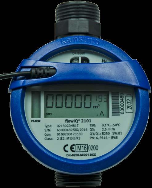

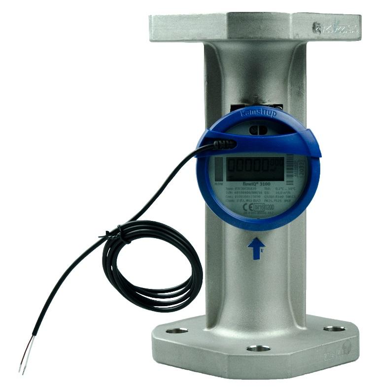
1 Technical Description Wired M-Bus Water Meters flowiq 2101/3100
2 TECHNICAL DESCRIPTION Wired M-Bus Water Meters flowiq 2101/3100 Contents 1 Introduction M-Bus M-Bus communication M-Bus water meter flowiq 2101/ Physical properties Design Applications Analysis Billing Emulation Controlling and regulating Installation Data communication Bus communication Communication interval Addressing forms Primary addressing Secondary addressing Enhanced secondary addressing Wildcard search with break detection M-Bus formats M-Bus master to M-Bus water meter M-Bus slave to M-Bus master REQ_UD2 -> RSP_UD REQ_UD1 -> ACK REQ_SKE -> RSP_SKE Information codes Status field Temporary error Datagram Reading loggers from flowiq 2101/3100 wired M-Bus Configuration of meter via the M-Bus network Setting Primary M-Bus address Setting Date and time Kamstrup A/S Technical Description _A1_GB_
3 Wired M-Bus Water Meters flowiq 2101/3100 TECHNICAL DESCRIPTION 7.3 Application select/reset Protocol RSP_UD data flowiq 2101/3100 data using Kamstrup specified VIFE RSP_SKE response from flowiq 2101/ Data header in RSP_UD DIF (Data Information Field) Primary VIF (Value Information Field) Special purpose VIF Main VIFE-code extension Kamstrup A/S Technical Description _A1_GB_


4 TECHNICAL DESCRIPTION Wired M-Bus Water Meters flowiq 2101/ Introduction This technical description describes the wired M-Bus interface of water meters flowiq 2101 and flowiq For further technical information about these water meters, please refer to their respective Technical Description. 1.1 M-Bus M-Bus is a bus system especially suited for communication with consumption meters. The system consists of an M-Bus Master and one or more meters with M-Bus interface. M-Bus is standardized in the European standard EN 13757, as well as in the OMS TR M-Bus communication Communication on the M-Bus is an asynchronous serial bit transmission in half duplex mode, which means that it is possible only to transmit one way at a time on the M-Bus. The framing of the communication is 1 start bit, 8 data bits, 1 parity bit (even) and 1 stop bit. The M-Bus is communicating via voltage modulation from the M-Bus Master to the M-Bus water meter and current modulation from the M-Bus water meter to the M-Bus Master. Communication media is via an ordinary two-wire cable. A twisted pair, non-shielded cable is recommended. 2 M-Bus water meter flowiq 2101/3100 The M-Bus water meter supports primary, secondary and enhanced secondary addressing as well as 300, 2400 and 9600 baud communication speed. The M-Bus water meter flowiq 2101/3100 are designed with manufacturer specified VIF extensions, so called VIFE codes. These VIFE codes are formatting the data, whereby decoding of the content is much easier, as when using manufacturer specified data. The connection of the M-Bus water meter and the M-Bus network is realized with a fixed two wire cable. 4 Kamstrup A/S Technical Description _A1_GB_
5 Wired M-Bus Water Meters flowiq 2101/3100 TECHNICAL DESCRIPTION 2.1 Physical properties The M-Bus interface is integrated in the flowiq 2101/3100. The bus is polarity independent. The M-Bus water meter have a max power consumption of 1 unit load (1.5 ma) drawn from the M-Bus Master. Rin: 440 Ohm Cin: 0.5nF Bus current and voltages according to EN Design The M-Bus water meters fulfil the requirements in the M-Bus standard EN 13757:2013 as well as the OMS TR02:2015 and can be used in a wide variety of applications using M-Bus protocol. 3.1 Applications The M-Bus water meters are designed with focus on high flexibility to fulfill a wide pallet of existing and future applications Analysis The flowiq 2101/3100 support high quantities of data and all relevant data for analysis can be read out. This is valid for both actual meter data as well as for target data Billing All relevant data for billing purposes can be read out from the flowiq 2101/ Emulation The wired M-Bus datagram in flowiq 2101/3100 is fixed and cannot be altered Controlling and regulating The water meter can deliver online data in intervals down to 15 seconds (however at reduced battery lifetime) for controlling and regulating purposes with a high communication speed. 4 Installation As M-Bus is polarity independent there is no + and to care about. Configuring the primary address can be done with METERTOOL HCW using an optical readout head or via the M-Bus network. It is recommended that the entire M-Bus system is not powered up during installation of new M- Bus water meters. Kamstrup A/S Technical Description _A1_GB_
6 TECHNICAL DESCRIPTION Wired M-Bus Water Meters flowiq 2101/ Data communication 5.1 Bus communication The M-Bus water meter design is based on the newest technology, offering high-speed communication as well as very frequent reading interval. The transmission speed is automatically detected by the M-Bus water meter. When the M-Bus water meter receives a message from the M-Bus Master on a certain speed, it will reply with the same speed. The M-Bus water meters flowiq 2101/3100 supports 300, 2400 and 9600 baud communication speed. 5.2 Communication interval In order to maintain the full 16 years battery lifetime of the water meter, the read out interval shall be longer than 1 minute. Since the most frequent integration interval in the flowiq 2101/3100 is 32 seconds, a more frequent reading is not recommended. A more frequent reading interval than 32 seconds will provide redundant information. 5.3 Addressing forms To make the M-Bus system operate with more M-Bus water meters connected, it is necessary to distinguish between the individual M-Bus water meter. This is done by means of following M-Bus ID numbers in each M-Bus meter: Primary address: , and the special addresses 0, 253, 254 and 255 M-Bus ID number: 8 digits Manufacturer ID: Always 2D2Ch for KAM for Kamstrup M-Bus water meter Version ID flowiq Fh Version ID flowiq Dh Device type ID: 06h = Volume warm, 16h = Volume cold Fabrication number: Serial number, 8 digits When the M-Bus Master sends a message on the M-Bus, some or all of the above ID numbers on the M-Bus water meters are encoded in the message. Thus, only the M-Bus water meter with the addressed ID numbers will reply. Manufacturer ID, Version ID and Fabrication number are permanently encoded into the M-Bus water meter and cannot be changed. 6 Kamstrup A/S Technical Description _A1_GB_
7 Wired M-Bus Water Meters flowiq 2101/3100 TECHNICAL DESCRIPTION Primary addressing A valid primary M-Bus address has a value between 000 and 250. The primary M-Bus address is either configured specific in the flowiq 2101/3100 or the last digits of the meter number are used. As factory default, the primary address in flowiq 2101/3100 equals to the last 3 digits of the meter number. If the last 3 digits are larger than 250 (e.g. 345) the first digit is ignored and the M-Bus water meter address is only determined by the last 2 digits (e.g. 45). During the ordering process specific primary addresses can be specified. Changing the primary address can be performed in following ways: Programming with METERTOOL HCW, via Optical Readout Head Remotely, via M-Bus master In connection with primary addressing of the M-Bus, two or more M-Bus water meters on the same M-Bus system cannot have the same primary address. However, in connection with secondary addressing or enhanced secondary addressing it is possible to distinguish M-Bus water meters with the same primary address on the same M-Bus. Standard address range for an M-Bus water meter is In addition to this, there are 4 special addresses that work as follows: Adr. 000: Ordinary primary address reserved for non-configured M-Bus water meter. Adr. 253: Used for secondary addressing. Only M-Bus water meters selected by (enhanced) secondary addressing will reply. Adr. 254: All M-Bus meters will reply to this address. The address can only be used in systems where only 1 M-Bus water meter is connected. Adr. 255: No M-Bus meter will reply to this address, but all will receive the message. This address makes it possible e.g. to change the baud rate, on an entire system at the same time, by sending only one telegram. Kamstrup A/S Technical Description _A1_GB_
8 TECHNICAL DESCRIPTION Wired M-Bus Water Meters flowiq 2101/ Secondary addressing A valid secondary M-Bus address has a value between and and is in the flowiq 2101/3100 identical to the unique serial number. In connection with secondary addressing, the M-Bus water meters are selected via the primary address 253 with its 8 byte long complete M-Bus ID consisting of: M-Bus ID number. Default from Kamstrup: The last 8 digits in the meter number / customer number (4 bytes) Manufacturer ID = ASCII characters KAM for Kamstrup encoded to the value 2D2Ch (2 bytes) Version/generation ID number for MULTICAL 21 = 34h (1 byte) Device type ID (1 byte) These 8 bytes make up the secondary address of the M-Bus water meter. It is possible to replace the individual bytes with wildcard characters. See chapter for further information. Selection of M-Bus water meter via secondary address (and deselecting other M-Bus water meter): Start character 68h L-field 0Bh L-field 0Bh Start character 68h C-field 53h or 73h A-field FDh CI-field 52h ID No. LSB 37 or FF BCD E.g. M-Bus ID number = ID No. 87 or FF BCD ID No. 11 or FF BCD ID No. MSB 04 or FF BCD Man. ID LSB 2Dh or FFh KAM encoded to 2D2Ch Man. ID MSB 2Ch or FFh Version ID 1Dh flowiq 2101 Version ID 1Fh flowiq 2101 Device ID 04h, 07h, 0Ah, 0Bh, 0Ch, or 0Dh (see also ID numbers) or FFh Checksum Xxh Stop character 16h As long as the M-Bus water meter is selected, it will reply to primary address 253, which is dedicated to secondary addressing. The M-Bus water meter is deselected either by sending a new selection via primary address 253 with a secondary address different from the one of the M-Bus water meter (by means of which another M-Bus meter may be selected, if necessary) or sending normalization (SND_NKE) to primary address Kamstrup A/S Technical Description _A1_GB_
9 Wired M-Bus Water Meters flowiq 2101/3100 TECHNICAL DESCRIPTION Enhanced secondary addressing A valid secondary M-Bus address has a value between (M-Bus ID No ) / (M-Bus fabrication No ) and is, in the flowiq 2101/3100, identical to the unique serial number. The M-Bus water meter secondary address can therefore be extended in order to comprise the 8 digit BCD fabrication number (4 bytes) identical with the serial number of the meter. This number is unique for each flowiq 2101/3100 and cannot be changed after the meter has been produced. In connection with enhanced secondary addressing, the M-Bus water meter is selected by adding fabrication number as an ordinary data record with DIF = 0Ch (for 4 bytes, 8 digit BCD) and VIF = 78h (for fabrication number) in the selection telegram after the secondary address. When a M-Bus water meter is selected via enhanced secondary address, it will reply to primary address 253, as it is with the ordinary secondary addressing. The M-Bus water meter is deselected either by sending a new selection via primary address 253 with an enhanced or ordinary secondary address different from the one from the M-Bus water meter (by means of which another M-Bus meter may be selected, if necessary) or sending a normalization (SND_NKE) to primary address 253. Selection of M-Bus water meter via enhanced secondary address (and deselecting other M-Bus water meter): Start character 68h L-field 11h L-field 11h Start character 68h C-field 53h or 73h A-field FDh CI-field 52h ID No. LSB 37 or FF BCD E.g. M-Bus ID number = ID No. 87 or FF BCD ID No. 11 or FF BCD ID No. MSB 04 or FF BCD Man. ID LSB 2Dh or FFh KAM encoded to 2D2Ch Man. ID MSB 2Ch or FFh Version ID 1Fh flowiq2101 Version ID 1Dh flowiq 3100 Device ID 16 (cold water), 06 (warm water) Record 0Ch DIF: 4 bytes, 8 digit BCD Fabrication. no. 78h VIF: Fabrication no. (serial no.), e.g.: Fabr. no. LSB 76 or FF BCD Fabr. no. 01 or FF BCD Fabr. no. 50 or FF BCD Fabr. no. MSB 02 or FF BCD Checksum Xxh Stop character 16h Kamstrup A/S Technical Description _A1_GB_
10 TECHNICAL DESCRIPTION Wired M-Bus Water Meters flowiq 2101/ Wildcard search with break detection The M-Bus water meter supports wild card search for an easy search for connected meters. Some or all digits of the meters secondary and/or enhanced secondary addresses can be replaced with wild cards when searching for meters in an M-Bus network. The integrated break detection functionality eases the meter search on the M-Bus network. The M-Bus water meter will not compare the wildcard characters with the equivalent digits in its own secondary and enhanced secondary address, and the M-Bus water meter will be selected if the other characters match. The 8 digits in the M-Bus ID number and the 8 digits in the fabrication number (= serial number) can each be replaced by the wildcard character Fh. The binary values Manufacturer ID (2 bytes), Version / generation ID (1 byte), and Device type ID (1 byte) in the secondary address may be replaced by the wildcard byte value FFh. The values for DIF = 0Ch (for 4 bytes, 8 digit BCD) and VIF = 78h (for fabrication number) in connection with enhanced secondary addressing cannot be replaced by wildcard values. By means of wildcard characters (BCD Fh) and values (binary FFh), an M-Bus Master can, relatively quickly, search the M-Bus for connected M-Bus water meters, without knowing the M-Bus water meters primary, secondary or enhanced secondary addresses in advance. 5.4 M-Bus formats The M-Bus protocol comprises following telegram / message format types: Single character Short frame Control frame Long frame Ack. = E5h Start = 10h Start = 68h Start = 68h C-Field L-Field = 3 L-Field = N + 3 A-Field L-Field = 3 L-Field = N + 3 Checksum Start = 68h Start = 68h Stop = 16h C-Field C-Field A-Field A-Field CI-Field CI-Field Checksum Stop = 16h Userdata (N = bytes) Checksum Stop = 16h The meaning of the C-Field C-FIELD: 40h SND_NKE 08h RSP_UD 0Bh RSP_SKE 49h REQ_SKE 53h SND_UD (FCB=0) 73h SND_UD (FCB =1) 5Ah REQ_UD1 (FCB=0) 7Ah REQ_UD1 (FCB =1) 5Bh REQ_UD2 (FCB=0) 7Bh REQ_UD2 (FCB =1) 43h SND_UD2 Note: In the default application the FCB bit is not used and the M-Bus water meter accepts both FCB = 0 and FCB = Kamstrup A/S Technical Description _A1_GB_
 The primary address of the M-Bus water meter in connection with secondary addressing. However, in connection with RSP _UD the M-Bus water meter still replies with its own primary address.")
11 Wired M-Bus Water Meters flowiq 2101/3100 TECHNICAL DESCRIPTION The meaning of the A-Field A-FIELD: xxh The primary address of the M-Bus water meter. FDh (253) The primary address of the M-Bus water meter in connection with secondary addressing. However, in connection with RSP _UD the M-Bus water meter still replies with its own primary address. FEh (254) Address to which all M-Bus water meters will reply. By using this address only one M-Bus water meter can be connected. The M-Bus water meter still replies with its own primary address. (255) Joint address where all M-Bus water meters can receive data from the M-Bus Master, but replies are not returned. The meaning of the CI-Field CI-FIELD: 50h Application select/reset. Select is used for logger reading applications. A reset will select the default application. 51h Normal transmission of SND_UD, data send (M-Bus Master to M-Bus water meter). 52h Opening for secondary addressing (selection of M-Bus water meter) is required. 72h Respond in variable structure. B8h Baud rate shift to 300 baud. BBh Baud rate shift to 2400 baud. BDh Baud rate shift to 9600 baud. BEh Baud rate shift to baud. 72h Long 12 bytes APL header in RSP_UD response from device 7Ah Short 4 bytes APL header in RSP_UD response from device 78h No APL header in RSP_UD response from device A0h Kamstrup specific from master to slave A1h Kamstrup specific from slave to master Note: As the flowiq 2101/3100 M-Bus water meters supports auto baud rate detection, it is not necessary to instruct them with a specific baud rate. Kamstrup A/S Technical Description _A1_GB_
12 TECHNICAL DESCRIPTION Wired M-Bus Water Meters flowiq 2101/ M-Bus master to M-Bus water meter Communication on the M-Bus is initiated by the M-Bus Master. After this the addressed M-Bus water meter replies. Basically, there are 2 different communication sequences (from M-Bus Master to M-Bus water meter): SEND -> CONFIRM REQUEST -> RESPONSE When using SEND -> CONFIRM the M-Bus Master sends a command or data to the M-Bus water meter, that replies with an acknowledgement (ACK). The acknowledgement (ACK) just means that the M-Bus water meter has received the telegram successfully, but it has not necessarily accepted the contents. When using REQUEST -> RESPONSE the M-Bus Master sends a request to the M-Bus water meter, which in return replies with a datagram according to the request. The M-Bus water meter only supports Mode 1 data format where all multi-byte data values to and from the M- Bus water meter are transmitted with Least Significant Byte (LSB) first. In the default application the FCB / FCV bit in the C-field is not used and the M-Bus water meter accepts both FCB = 0 and FCB = 1. The M-Bus water meter does not use DFC (Data Flow Control) / ACD (Access Demand) bits, which means that both bits will always have the value 0 in the C-Field from the M-Bus water meter. The following describes the individual M-Bus telegrams, from M-Bus Master to M-Bus water meter and from M-Bus water meter to M-Bus Master, that are supported. REQ_UD1: Short frame. Request for time-critical data alarm. Start character C-field A-field Checksum Stop character 10h 5Ah or 7A xxh or FDh Xxh 16h REQ_UD2: Short frame. Request for data from the M-Bus interface. Start character C-field A-field Checksum Stop character 10h 5Bh or 7B xxh or FDh xxh 16h REQ_SKE: Short frame. Status request. Start character C-field A-field Checksum Stop character 10h 49h xxh or FDh xxh 16h 12 Kamstrup A/S Technical Description _A1_GB_
13 Wired M-Bus Water Meters flowiq 2101/3100 TECHNICAL DESCRIPTION SND_NKE: Short frame. Normalizes the M-Bus water meter. Start character C-field A-field Checksum Stop character 10h 40h xxh or FDh xxh 16h SND_UD: Long frame, Data to the M-Bus water meter. Start character 68h L-field xxh length field = number of data bytes N + 3 L-field xxh length field repeated Start character 68h C-field 53h (FCB=0) or 73h (FCB=1) = SND_UD A-field xxh or FDh CI-field xxh 51h = data send, 52h = secondary address selection Data byte 1 xx : : : : Data byte 1 xx Checksum xxh Stop character 16h 5.6 M-Bus slave to M-Bus master RSP_UD: Long frame. Data to M-Bus Master. See telegram later. RSP_SKE: Short frame. Data to M-Bus Master. See telegram later. ACK: Single control character. Data format from M-Bus Master received successfully. Description of the codes of the individual formats can be viewed later in this document. Communication takes place in following sequences: REQ_UD2 -> RSP_UD To collect meter data, from the M-Bus water meter, an REQ_UD2 is transmitted from the M-Bus Master. The M-Bus water meter checks the message, and if it is correct, the M-Bus water meter returns with an RSP_UD, which is meter data packed according to the M-Bus format for RSP_UD. An example of a RSP_UD datagram can be viewed later in the manual. Kamstrup A/S Technical Description _A1_GB_
14 TECHNICAL DESCRIPTION Wired M-Bus Water Meters flowiq 2101/ REQ_UD1 -> ACK REQ_UD1 from the M-Bus Master is a request for time-critical (alarm) data from the M-Bus water meter. The flowiq 2101/3100 M-Bus water meter does not support time-critical data (alarm protocol), but it replies with an ACK (link layer receipt) when receiving REQ_UD1, which means that the M-Bus water meter does not have any time-critical (alarm) data to transmit. In this way, the M-Bus water meter will function in M-Bus systems with other M-Bus interface supporting timecritical data (alarm protocol) REQ_SKE -> RSP_SKE REQ_SKE from the M-Bus Master is a request for communication status and for information on whether the M-Bus water meter has any time-critical (alarm) data to send. When receiving an REQ_SKE the M-Bus water meter replies with an RSP_SKE, but as the M-Bus water meter does not support time-critical data (alarm protocol), and cannot have overflow in its input buffer, the status bits ACD (Access Demand) and DFC (Data Flow Control) will always be = 0 in the M-Bus water meter reply, which means that the M-Bus water meter does not have any time-critical (alarm) data to send and has no buffer overflow. Therefore, the M-Bus water meter will function in M-Bus systems with other M-Bus interface supporting timecritical data (alarm protocol) and using communication status bit. SND_NKE -> ACK The M-Bus Master normalizes the M-Bus water meter with an SND_NKE and the M-Bus water meter acknowledges successful receipt of the message by means of an ACK. An SND_NKE to primary address 253 will deselect the M-Bus water meter, if it was selected by means of secondary or enhanced secondary addressing. SND_UD -> ACK The M-Bus Master wishes to send data to the M-Bus water meter, or to select/deselect the M-Bus water meter via secondary or enhanced secondary addressing. The M-Bus water meter acknowledges successful receipt of the SND_UD telegram by means of an ACK. The acknowledgement (ACK) just means that the M-Bus water meter has received the telegram successfully in the Data Link Layer and is as such no guarantee that the M-Bus water meter has accepted the contents of the Application Layer. Therefore, when receiving an SND_UD command with a new baud rate, the M-Bus water meter will acknowledge receipt by means of an ACK, even though it ignores the contents, as the M-Bus water meter automatically detects the baud rate on receipt. 5.7 Information codes flowiq 2101/3100 indicates in the display, and in the wired M-Bus datagram, if a special state in the meter, called info codes, are present: DRY: Meaning that the meter is not water filled, in this case nothing is measured. REVERSE: Meaning that the water is flowing in the wrong direction in the meter. LEAK: Meaning that the water has been running for more than 24 hours. BURST: Meaning that the water flow is constantly high for more than 30 minutes. 14 Kamstrup A/S Technical Description _A1_GB_
15 Wired M-Bus Water Meters flowiq 2101/3100 TECHNICAL DESCRIPTION TAMPER: Meaning that the meter has been disassembled in an attempt of fraud. The info code will disappear from the display and from the wired M-Bus datagram, when the condition that initiated it disappears. Info codes initiate the Temporary error (bit 4) in the status field Status field flowiq 2101/3100 info codes are mapped to the error bit Temporary error (bit 4) when any info code is active. Further, the Power Low (bit 2) in the status field is set, when battery power is low. The Status field in the M-Bus data header can have one of the following values, or the sum of more values: Status field value 00h 04h 10h 14h Temporary error Description No info code Power Low on battery Temporary Error Power Low and Temporary Error Temporary Error (Bit 4) is set when one of the info codes is active in flowiq 2101/3100. Kamstrup A/S Technical Description _A1_GB_
16 TECHNICAL DESCRIPTION Wired M-Bus Water Meters flowiq 2101/ Datagram The datagram in flowiq 2101/3100 M-Bus water meter has a fixed data content. Previously, Kamstrup has placed a number of special registers like configuration values in the manufacturer specified part of the telegram. This has required quite extensive knowledge of the meter in order to decode and format these data correct. In order to be able to decode special data registers in an easier way, Kamstrup has taken the approach to define a number of manufacturer VIF extensions so called VIFE. The outcome is that most reading systems can show the special registers in clear reading. Below an example showing manufacturer specified data vs. Manufacturer specified VIFE: Manufacturer specified data Special B C9 A EE E0 B x D C x Manufacturer specified VIFE INT Inst Manufacturer specific ->0F INT Inst Manufacturer specific ->11 INT Inst Manufacturer specific ->12 INT Inst Manufacturer specific ->1A 16 Kamstrup A/S Technical Description _A1_GB_
17 Wired M-Bus Water Meters flowiq 2101/3100 TECHNICAL DESCRIPTION The datagram is fixed and cannot be changed. The datagram from flowiq 3100 large meter versions differs slightly from the one in flowiq 2101, because these large meters do not measure the water temperature. flowiq 2101 and flowiq and 2.5 and 4.0 m 3 /h M-Bus data header Actual data Monthly data Meter data M-Bus ID Manufacturer ID Version ID Device type Access counter Status (set if any info codes is active) Configuration (not used) Monthly target meter reading Min Flow 1 Month Max Flow 1 Month Min water temp Month Avg. water temp Month Min Ambient temp Month Max Ambient temp Month Avg. Ambient temp Month Target date Water meter reading (volume) Volume reverse Hour counter Actual flow Actual water temperature Actual ambient temperature Min Flow Day 1) Max Flow Day 1) Min water temp Day 1) Avg. water temp Day 1) Min ambient temp Day 1) Max ambient temp Day 1) Avg. ambient temp Day 1) Date/Time flowiq 3100 Q3 = 6.3 m 3 /h and higher. M-Bus data header Actual data Monthly data Meter data M-Bus ID Manufacturer ID Monthly target meter reading Min Flow 1 Month Version ID Max Flow 1 Month Min Ambient temp Month Device type Max Ambient temp Month Access counter Avg. Ambient temp Month Status (info codes) Target date Configuration (not used) Water meter reading (volume) Volume reverse Hour counter Actual flow Actual ambient temperature Min Flow Day 1) Max Flow Day 1) Min ambient temp Day 1) Max ambient temp Day 1) Avg. ambient temp Day 1) Date/Time Information codes Config number Meter Type (main / sub type) Meter SW Revision Info Config number Meter Type (main / sub type) Meter SW Revision 1) The daily flow and temperatures are the actual daily minimum, average or maximum values logged from midnight until the present reading time. 6 Reading loggers from flowiq 2101/3100 wired M-Bus The loggers in the flowiq 2101/3100 can only be read with an optical reading head, the optical eye in the meter and the program LogView. 7 Configuration of meter via the M-Bus network Following parameters can be sent to the M-Bus water meter, in order to change the configuration of the flowiq 2101/3100: Primary M-Bus address Date and time Selection of the M-Bus water meter via secondary address or enhanced secondary address, and application select/reset is obtained via SND_UD telegram from the M-Bus Master to the M-Bus water meter. Selection of device for secondary addressing is made by CI-field = 52h, and application select/reset by CI-field = 50h. Kamstrup A/S Technical Description _A1_GB_
18 TECHNICAL DESCRIPTION Wired M-Bus Water Meters flowiq 2101/3100 The M-Bus water meter will also reply with an acknowledgement (ACK) when receiving a set of baud rate telegrams (CI-field = B8h... BFh), but will ignore the contents, as the M-Bus interface is furnished with automatic baud rate detection. The individual datagram for writing data in the M-Bus water meter are shown subsequently. 7.1 Setting Primary M-Bus address A dedicated register in the flowiq 2101/3100 is used for storing the primary address. This register may be overwritten with a new M-Bus primary address using the datagram format below. Start character 68h L-field 06h L-field 06h Start character 68h C-field 53h (FCB=0) or 73h (FCB=1) A-field xxh or FDh CI-field 51h Record 01h DIF: 1 byte, binary Address 7Ah VIF: Address Primary add. xxh XX = 01h... FAh. For primary address = Checksum xxh Stop character 16h Note: During the ordering process the primary address for each meter can be specified. Normally it is the last 2-3 digits of the customer number. 18 Kamstrup A/S Technical Description _A1_GB_
19 Wired M-Bus Water Meters flowiq 2101/3100 TECHNICAL DESCRIPTION 7.2 Setting Date and time To synchronize the time in the meter towards a main application real time clock, the time and date may be sent to the flowiq 2101/3100 using the datagram format below. To avoid disturbing the internal loggers, setting the time must be done in due time before or after an hour shift. Typically the date/time is set once each 24 hour. Start character 68h L-field 09h L-field 09h Start character 68h C-field 53h (FCB=0) or 73h (FCB=1) A-field xxh or FDh CI-field 51h Record 04h DIF: 4 bytes, compound data type F Date and time 6Dh VIF: Date and time, e.g :10 standard time, valid Date, time LSB 0Ah IV, 0, MI5, MI4, MI3, MI2, MI1, MI0 Date, time 2Dh SU, HY1, HY0, H4, H3, H2, H1, H0 Date, time 82h Y2, Y1, Y0, D4, D3, D2, D1, D0 Date, time MSB 09h Y6, Y5, Y4, Y3, M3, M2, M1, M0 Checksum Xxh Stop character 16h As flowiq 2101/3100 uses two digits to indicate year ( ), the flowiq 2101/3100 M-Bus always sends information concerning year as (bit HY1:HY0 always = 01 in Date and time record, VIF = 6Dh and DIF = 04h, compound data type F). Note: See EN Annex A Coding of data records for details on how to decode the Date/Time data type. 7.3 Application select/reset In connection with application reset the flowiq 2101/3100 M-Bus water meter returns an ACK. Nothing further happens and nothing is reset. Kamstrup A/S Technical Description _A1_GB_
20 TECHNICAL DESCRIPTION Wired M-Bus Water Meters flowiq 2101/ Protocol When using M-Bus Masters and/or reading software of another manufacturer, the same commands must be used. The flowiq 2101/3100 M-Bus water meter only support commands stated in this description. The datagram is fixed. 8.1 RSP_UD data flowiq 2101/3100 data using Kamstrup specified VIFE Complete description of reply with examples of readings from the M-Bus water meter (RSP_UD) on request from M-Bus Master (REQ_UD2): DIF = Data Information Field, DIFE = DIF Extension VIF = Value Information Field, VIFE = VIF Extension RSP_UD: Standard profile monthly target data, shown for a Version ID for flowiq 2101/3100 water meter. flowiq 2101/flowIQ 3100: Byte Field Value Description 1 Start character 68h 2 L-field 8Ah Length 138 bytes 3 L-field 8Ah Length 138 bytes 4 Start character 68h 5 C-field 08h Code for RSP_UD 6 A-field 65h Primary address (eg. 101) 7 CI-field 72h 8 ID Number 78 BCD E.g.: ID = BCD BCD BCD 12 Man. ID 2Dh Manufacturer ID for Kamstrup A/S (KAM) 13 2Ch 14 Version ID 1Fh Version ID for flowiq2101 (or 1Dh for flowiq3100) 15 Device ID 16h E.g.: 16h = Cold Water 16 Access Number xxh Increments after each RSP_UD. 17 Status Field 00h Error message. 00 = no error. 18 Config 00h Not used 19 00h 20 DIF 04h 4 bytes binary 21 VIF 13h Volume in m 3 with 3 decimals 22 Volume 72h m Fh 24 01h 25 00h 26 DIF 04h 4 bytes binary 27 VIF 93h Reverse volume in m 3 with 3 decimals 28 3Ch 29 Volume Reverse 13h m h 31 00h 20 Kamstrup A/S Technical Description _A1_GB_
21 Wired M-Bus Water Meters flowiq 2101/3100 TECHNICAL DESCRIPTION flowiq 2101/flowIQ 3100: Byte Field Value Description 32 00h 33 DIF 04h 4 bytes binary 34 VIF 22h Duration of meter power on in hours 35 Hour Counter 30h 304 hours 36 01h 37 00h 38 00h 39 DIF 02h 2 bytes binary 40 VIF 3Bh Flow in l/h 41 Flow 05h 5 l/h 42 00h 43 DIF 01h 1 byte binary 44 VIF 5Bh Media temperature in C 45 Tmedia 08h 8 C 46 DIF 01h 1 byte binary 47 VIF 67h Ambient temperature in C 48 Tambient 25h 37 C 49 DIF 22h 2 byte binary, minimum value 50 VIF 3Bh Flow in l/h 51 Min Flow 05h 5 l/h 52 00h 53 DIF 12h 2 byte binary, maximum value 54 VIF 3Bh Flow in l/h 55 Max Flow 2Ah 298 l/h 56 01h 57 DIF 21h 1 byte binary, minimum value 58 VIF 5Bh Media temperature in C 59 Min Tmedia 05h 5 C 60 DIF 01h 1 byte binary 61 VIF DBh Kamstrup specific vif: average media temperature 62 FFh 63 0Fh 64 Avg Tmedia 07h 7 C 65 DIF 21h 1 byte binary, minimum value 66 VIF 67h Ambient temperature in C 67 Min Tambient 0Eh 14 C 68 DIF 11h 1 byte binary, maximum value 69 VIF 67h Ambient temperature in C 70 Max Tambient 28h 40 C 71 DIF 01h 1 byte binary 72 VIF E7h Kamstrup specific average ambient temperature 73 FFh 74 0Fh 75 Avg Tambient 1Ah 26 C 76 DIF 04h 4 byte binary 77 VIF 6Dh Type F (Compound CP32) 78 Date/Time 02h E.g. CP32: h = : h 80 37h 81 23h 82 DIF 44h 4 byte binary, monthly value 83 VIF 13h Volume in m 3 with 3 decimals 84 V1 Target A0h m 3 Kamstrup A/S Technical Description _A1_GB_
22 TECHNICAL DESCRIPTION Wired M-Bus Water Meters flowiq 2101/3100 flowiq 2101/flowIQ 3100: Byte Field Value Description 85 05h 86 01h 87 00h 88 DIF 62h 2 byte binary, monthly minimum value 89 VIF 3Bh Flow in l/h 90 Min Flow Month 02h 2 l/h 91 00h 92 DIF 52h 2 byte binary, monthly maximum value 93 VIF 3Bh Flow in l/h 94 Max Flow Month D4h 468 l/h 95 01h 96 DIF 61h 1 byte binary, monthly minimum value 97 VIF 5Bh Media temperature in C 98 Min Tmedia Month 04h 4 C 99 DIF 41h 1 byte binary, monthly value 100 VIF DBh Kamstrup specific vif: media ambient temperature 101 FFh 102 0Fh 103 Avg Tmedia Month 09h 9 C 104 DIF 61h 1 byte binary, monthly minimum value 105 VIF 67h Ambient temperature in C 106 Min Tambient Month 10h 16 C 107 DIF 51h 1 byte binary, monthly maximum value 108 VIF 67h Ambient temperature in C 109 Max Tambient Month 24h 36 C 110 DIF 41h 1 byte binary, monthly value 111 VIF E7h Kamstrup specific vif: average ambient temperature 112 FFh 113 0Fh 114 Avg Tambient Month 18h 24 C 115 DIF 42h 2 byte binary, monthly value 116 VIF 6Ch Type G (Compound CP16) 117 Target Date 21h CP16: 2321h = h 119 DIF 02h 2 byte binary 120 VIF FFh Kamstrup specific vif: info code h 122 Info 00h 00 = no info codes h 124 DIF 06h 6 byte binary 125 VIF FFh Kamstrup specific vif: Config number h 127 Config Number DDh Config no: DEDDh = DEh h h h h 133 DIF 02h 2 byte binary 134 VIF FFh Kamstrup specific vif: Meter type 135 1Ah 136 Meter Type 01h Meter Type: flowiq2101 Cold Water h 22 Kamstrup A/S Technical Description _A1_GB_
23 Wired M-Bus Water Meters flowiq 2101/3100 TECHNICAL DESCRIPTION flowiq 2101/flowIQ 3100: Byte Field Value Description 138 DIF 02h 2 byte binary 139 VIF FDh Kamstrup specific vif: Software revision 140 0Eh 141 SW Revision 01h Software revision: D h 143 Checksum xxh 144 Stop Character 16h flowiq 3100: Byte Field Value Description 1 Start character 68h 2 L-field 77h Length 119 bytes 3 L-field 77h Length 119 bytes 4 Start character 68h 5 C-field 08h Code for RSP_UD 6 A-field 65h Primary address (e.g. 101) 7 CI-field 72h 8 ID Number 78 BCD E.g.: ID = BCD BCD BCD 12 Man. ID 2Dh Manufacturer ID for Kamstrup A/S (KAM) 13 2Ch 14 Version ID 1Dh Version ID for flowiq Device ID 16h E.g.: 16h = Cold Water 16 Access Number xxh Increments after each RSP_UD. 17 Status Field 00h Error message. 00 = no error. 18 Config 00h Not used 19 00h 20 DIF 04h 4 bytes binary 21 VIF 13h Volume in m 3 with 3 decimals 22 Volume 72h m Fh 24 01h 25 00h 26 DIF 04h 4 bytes binary 27 VIF 93h Reverse volume in m 3 with 3 decimals 28 3Ch 29 Volume Reverse 13h m h 31 00h 32 00h 33 DIF 04h 4 bytes binary 34 VIF 22h Duration of meter power on in hours 35 Hour Counter 30h 304 hours 36 01h 37 00h 38 00h 39 DIF 02h 2 bytes binary 40 VIF 3Bh Flow in l/h 41 Flow 05h 5 l/h 42 00h Kamstrup A/S Technical Description _A1_GB_
24 TECHNICAL DESCRIPTION Wired M-Bus Water Meters flowiq 2101/3100 flowiq 3100: Byte Field Value Description 43 DIF 01h 1 byte binary 44 VIF 67h Ambient temperature in C 45 Tambient 25h 37 C 46 DIF 22h 2 byte binary, minimum value 47 VIF 3Bh Flow in l/h 48 Min Flow 03h 3 l/h 49 00h 50 DIF 12h 2 byte binary, maximum value 51 VIF 3Bh Flow in l/h 52 Max Flow 73h 371 l/h 53 01h 54 DIF 21h 1 byte binary, minimum value 55 VIF 67h Ambient temperature in C 56 Min Tambient 0Eh 14 C 57 DIF 11h 1 byte binary, maximum value 58 VIF 67h Ambient temperature in C 59 Max Tambient 28h 40 C 60 DIF 01h 1 byte binary 61 VIF E7h Kamstrup specific average ambient temperature 62 FFh 63 0Fh 64 Avg Tambient 1Ah 26 C 65 DIF 04h 4 byte binary 66 VIF 6Dh Type F (Compound CP32) 67 Date/Time 02h E.g. CP32: h = : h 69 37h 70 23h 71 DIF 44h 4 byte binary, monthly value 72 VIF 13h Volume in m 3 with 3 decimals 73 V1 Target A0h m h 75 01h 76 00h 77 DIF 62h 2 byte binary, monthly minimum value 78 VIF 3Bh Flow in l/h 79 Min Flow Month 03h 3 l/h 80 00h 81 DIF 52h 2 byte binary, monthly maximum value 82 VIF 3Bh Flow in l/h 83 Max Flow Month A9h 425 l/h 84 01h 85 DIF 61h 1 byte binary, monthly minimum value 86 VIF 67h Ambient temperature in C 87 Min Tambient Month 10h 16 C 88 DIF 51h 1 byte binary, monthly maximum value 89 VIF 67h Ambient temperature in C 90 Max Tambient Month 24h 36 C 91 DIF 41h 1 byte binary, monthly value 92 VIF E7h Kamstrup specific vif: average ambient temperature 93 FFh 94 0Fh 95 Avg Tambient Month 18h 24 C 24 Kamstrup A/S Technical Description _A1_GB_
25 Wired M-Bus Water Meters flowiq 2101/3100 TECHNICAL DESCRIPTION flowiq 3100: Byte Field Value Description 96 DIF 42h 2 byte binary, monthly value 97 VIF 6Ch Type G (Compound CP16) 98 Target Date 21h CP16: 2321h = h 100 DIF 02h 2 byte binary 101 VIF FFh Kamstrup specific vif: info code h 103 Info 00h 00 = no info codes h 105 DIF 06h 6 byte binary 106 VIF FFh Kamstrup specific vif: Config number h 108 Config Number DDh Config no: DEDDh = DEh h h h h 114 DIF 02h 2 byte binary 115 VIF FFh Kamstrup specific vif: Meter type 116 1Ah 117 Meter Type 03h Meter Type: flowiq3100 Cold Water h 119 DIF 02h 2 byte binary 120 VIF FDh Kamstrup specific vif: Software revision 121 0Eh 122 SW Revision 01h Software revision: D h 124 Checksum xxh 125 Stop Character 16h Note: A target value may read as zero, until passing the set target date. 8.2 RSP_SKE response from flowiq 2101/3100 Reply from the M-Bus water meter (RSP_SKE) on request for communication status from M-Bus Master (REQ_SKE): RSP_SKE: Start 10h C-field 0B h Code for RSP_SKE (ACD bit and DFC bit is always = 0) A-field 6A h Slave address (e.g. address = 106) Checksum xx h Stop 16 h The ACD (Access Demand) and DFC (Data Flow Control) status bits (bit 5 and bit 4 respectively) in the C-field will always be = 0 in the reply, which means that the M-Bus water meter does not have any time-critical (alarm) data to send and has no buffer overflow, as the M-Bus water meter does not support time-critical data (alarm protocol). But the (empty) RSP_SKE reply to REQ_SKE request ensures, that the M-Bus water meter will function in M-Bus systems with other M-Bus interfaces, supporting time-critical data (alarm protocol) and using communication status bit. Kamstrup A/S Technical Description _A1_GB_
26 TECHNICAL DESCRIPTION Wired M-Bus Water Meters flowiq 2101/ Data header in RSP_UD Data Value Type Description ID-NO Xxh A M-Bus ID number 10 1 / M-Bus ID number 10 0 ID-NO Xxh A M-Bus ID number 10 3 / M-Bus ID number 10 2 ID-NO Xxh A M-Bus ID number 10 5 / M-Bus ID number 10 4 ID-NO Xxh A M-Bus ID number 10 7 / M-Bus ID number 10 6 MANUFACTURER C Manufacturer Id 2D [ascii K - 64] [ascii A 64] 32+ MANUFACTURER C Manufacturer Id 2C [ascii M - 64] ISO standard VERSION ID 1Fh 1Dh C M-Bus version ID for flowiq2101 M-Bus version ID for flowiq3100 DEVICE TYPE ID Xxh C 06h = Volume warm 16h = Volume cold ACCESS NO Xxh C Counts 1 up for each data transmission to M-Bus Master STATUS Xxh C 00h = No Info code 04h = Power Low on battery 10h = Temporary error 14h = Power Low and Temporary error at the same time ENCRYPTION 00h C Encryption not used in Wired M-Bus CONFIGURATION ENCRYPTION CONFIGURATION 00h C Encryption not used in Wired M-Bus 26 Kamstrup A/S Technical Description _A1_GB_
27 Wired M-Bus Water Meters flowiq 2101/3100 TECHNICAL DESCRIPTION 8.4 DIF (Data Information Field) The DIF codes holds additional information regarding the formatting of the data-value in the records, whether data is binary, real or BCD. Some examples of DIF codes are listed in the table below. Subject Value Hex Description PRIMARY ADDRESS h 8 bit binary, Current Value, Type C INFO CODE h 16 bit binary, Current Value, Type B METER TYPE h 16 bit binary, Current Value, Type B SOFTWARE REVISION h 16 bit binary, Current Value, Type B VOLUME (Meter reading and reverse) h 32 bit binary, Current Value, Type B TEMPERATURES Actual h 8 bit binary, Current Value, Type B TEMPERATURES minimum daily h 8 bit binary, Minimum Value, Type B TEMPERATURES average daily h 8 bit binary, Current Value, Type B TEMPERATURES maximum daily h 8 bit binary, Maximum Value, Type B TEMPERATURES minimum monthly h 8 bit binary, Minimum Monthly Value, Type B TEMPERATURES average monthly h 8 bit binary, Current Monthly Value, Type B TEMPERATURES maximum monthly h 8 bit binary, Maximum Monthly Value, Type B TARGET DATE h 16 bit binary, Compound Data, Type G FLOW actual h 16 bit binary, Current Value, Type B FLOW minimum daily h 16 bit binary, Minimum Value, Type B FLOW maximum daily h 16 bit binary, Maximum Value, Type B FLOW maximum monthly h 16 bit binary, Maximum Monthly Value, Type B FLOW minimum monthly h 16 bit binary, Minimum Monthly Value, Type B HOUR COUNTER h 32 bit binary, Current Value, Type B DATE AND TIME h 32 bit binary, Compound Data, Type F TARGET DATE h 16 bit Integer, Historical Value, Type G TARGET VOLUME h 32 bit binary, Historical Value, Type B OTHERS h 32 bit binary, Current Value, Type B Note: See EN Annex A Coding of data records for details on how to decode data types. Kamstrup A/S Technical Description _A1_GB_
28 TECHNICAL DESCRIPTION Wired M-Bus Water Meters flowiq 2101/ Primary VIF (Value Information Field) The VIF codes contain both unit and scaling factor for the record value. The VIF codes for volume and flow will, as far as possible, reflect the display reading in the water meter as regards unit, decimal point and number of decimals. Thus, the VIF codes for these data values will vary depending on the configuration of the flowiq 2101/3100. The relevant VIF codes are listed in the table below. VIF (HEX) Coding (binary) Subject Unit Size 13h Meter reading m³*10-3 m³ h Meter reading m³ 10-2 m³ h Meter reading m³ 10-1 m³ h Meter reading m³ m³ h Volume Reverse m³*10-3 m³ h Volume Reverse m³ 10-2 m³ h Volume Reverse m³ 10-1 m³ h Volume Reverse m³ m³ h Hour counter Hours Hours 3Bh Flow l/h m³/h Bh Water temperature C C 67h Ambient temperature C C 3Bh Min. flow since midnight l/h m³/h Bh Max. flow since midnight l/h m³/h Bh Minimum water temperature C C since midnight DBh Average water temperature C C since midnight 67h Minimum ambient C C temperature since midnight 67h Maximum ambient C C temperature since midnight E7h Average ambient C C temperature since midnight 6Dh Date and time F-Type Date and time 13h Meter reading the first day of m³*10-3 m³ 10-3 actual month 14h Meter reading the first day of m³ 10-2 m³ 10-2 actual month 15h Meter reading the first day of m³ 10-1 m³ 10-1 actual month 16h Meter reading the first day of m³ m³ 10 0 actual month 3Bh Min. flow last month l/h m³/h Bh Max. flow last month l/h m³/h Bh Minimum water temperature C C last month DBh Average water temperature C C last month 67h Minimum ambient temperature last month C C 28 Kamstrup A/S Technical Description _A1_GB_
29 Wired M-Bus Water Meters flowiq 2101/3100 TECHNICAL DESCRIPTION 67h Maximum ambient C C temperature last month E7h Average ambient C C temperature last month 6Ch Target date CP-16 Date FFh Info code register FFh Configuration number FFh Meter main and sub -type FDh Software revision 78h Serial number A-Type Serial no. 79h ID no. A-Type Meter no. 7Ah Primary address C-Type Primary address Note: See EN table 26 for a complete list of primary VIF s and for the compound CP-16 format. CODING: SUBJECT: UNIT: SIZE: VIF-field coding in the data package Subject in the record Unit required Unit programmed in VIF The M-Bus water meter uses information from the meter to place units, decimal points and number of decimals on the values in the M-Bus telegram, ensuring that they correspond to the values read on the meter display, as far as it is supported in the M-Bus protocol. 8.6 Special purpose VIF Special purpose VIF codes used. VIF (hex) Coding Description Purpose FDh Second Extension of VIF codes True VIF in first VIFE using Table 11 (EN ) FFh Manufacturer specific extension VIFE s and data following are manufacturer specific Note: See EN table 27 for a complete list of special purpose VIF s 8.7 Main VIFE-code extension If primary VIF is 0FDh, a VIFE will follow. The following VIFE codes are used. VIF (hex) Coding Description Usage 0Eh Metrology firmware version Legal meter software revision 17h Error flags (binary) Meter Error (info) code (see section 5.7.2) Note: See En table 28, for a complete list of VIFE codes. Kamstrup A/S Technical Description _A1_GB_
30 TECHNICAL DESCRIPTION Wired M-Bus Water Meters flowiq 2101/ End of document Kamstrup A/S Technical Description _A1_GB_
M-Bus Slaves for MULTICAL 601
 Technical Description M-Bus Slaves for MULTICAL 601 Kamstrup A/S Industrivej 28, Stilling DK-8660 Skanderborg TEL: +45 89 93 10 00 FAX: +45 89 93 10 01 E-MAIL: energi@kamstrup.dk WEB: www.kamstrup.com
SF-586x: M-Bus Extension
 Dorfstrasse 34 D 15834 Gross Machnow SF-586x: M-Bus Extension Revision : 1.04 Inhaltsverzeichnis 1 Preface...3 1.1 Validaty...3 1.2 Abbreviations...3 1.3 Checksum...3 1.4 Telegram format...4 1.4.1 Single
OMS Vol.2 Primary Elster Implementation
 All rights reserved by Elster GmbH Elster GmbH R&D Residental Gas Metering Strotheweg 1 49504 Lotte (Bueren) T: +49 (0)541/1214-0 F: +49 (0)541/1214-370 OMS Vol.2 Primary 2.0.0 Elster Implementation AE.02:02.01:01.01
M-Bus Modules. Data sheet. for MULTICAL 403
 Data sheet M-Bus Modules for MULTICAL 403 For billing, analysis and regulation purposes Configurable datagrams Read out of loggers Up to 19200 baud communication speed Primary/secondary/enhanced secondary
COMMUNICATION M-BUS PROTOCOL CE4DMID0M (MBus meter)
") COMMUNICATION M-BUS PROTOCOL CE4DMID0M (MBus meter) PR144 Rev A Fw. Version 2.00 16/02/2018 Pag. 1/17 1. Standard M-Bus telegrams... 3 1.1 Request for Data (REQ_UD2 )... 3 1.2 Details of telegrams 1,2,3...
COMMUNICATION M-BUS PROTOCOL CE4DMID0M (MBus meter) PR144 Rev A Fw. Version 2.00 16/02/2018 Pag. 1/17 1. Standard M-Bus telegrams... 3 1.1 Request for Data (REQ_UD2 )... 3 1.2 Details of telegrams 1,2,3...
M-BUS Standard acc. EN AE.05:04.01: Protocol Specification
 M-BUS Standard acc. EN 13757 AE.05:04.01:01.01 Protocol Specification Manufacturer: Elster GmbH Strotheweg 1 49504 Lotte Germany Änd.Nr.: 510400 1000470754 000 00 ZSD A Seite 1 von 17 Contents 1. Introduction...
M-Bus protocol CALEC energy master
 M-Bus protocol CALEC energy master Manufacturer: Device: Firmware version: INTEGRA METERING AG CALEC energy master 1.03.XX or higher Manufacturer code: 05B4h Device version: D0 (inactive), D1(Flow), D2
FLOW 38 v8.x. M-Bus communication protocol specification
 FLOW 38 v8.x M-Bus communication protocol specification d.v. 21/6/2013 Transmission service used The master is the primary station which initiates all the messages transfers, the satellites stations are
GNM1D M-BUS COMMUNICATION PROTOCOL. Revision 0
 GNM1D M-BUS COMMUNICATION PROTOCOL Revision 0 Index 1.1 1.2 Introduction... 3 M-BUS functions... 3 1.2.1 Single control character procedure SND_NKE... 3 1.2.2 Request/Respond Procedure (REQ/RSP)... 4 1.2.3
EM111-EM112 M-BUS COMMUNICATION PROTOCOL. Revision 4.0
 EM111-EM112 M-BUS COMMUNICATION PROTOCOL Revision 4.0 Index 1.1 Introduction...3 1.2 M-BUS functions...3 1.2.1 Single control character procedure SND_NKE...3 1.2.2 Request/Respond Procedure (REQ/RSP)...4
Wired M-Bus Modules. Data sheet. for MULTICAL 403 and 603
 Data sheet Wired M-Bus Modules for MULTICAL 403 and 603 For billing, analysis and controlling purposes Configurable datagrams Readout of loggers Up to 19200 baud communication speed Primary/secondary/enhanced
FALCON MJ Pulse/M-Bus operating instructions M-Bus module for Honeywell / Elster M100i and M120i waters meters
 FALCON MJ Pulse/M-Bus operating instructions M-Bus module for Honeywell / Elster M100i and M120i waters meters Content 1 Description of functions... 2 2 Installation and commissioning... 3 2.1 Installing
GNM3D M-BUS COMMUNICATION PROTOCOL. Revision 1
 GNM3D M-BUS COMMUNICATION PROTOCOL Revision 1 Index 1.1 1.2 Introduction... 3 M-BUS functions... 3 1.2.1 Single control character procedure SND_NKE... 3 1.2.2 Request/Respond Procedure (REQ/RSP)... 4 1.2.3
COMMUNICATION M-BUS PROTOCOL PR 118
 COMMUNICATION M-BUS PROTOCOL PR 118 CE4DT CONTO D4 Pd 03/01/2017 Pag. 1/27 CONTENTS 1. Standard M-Bus telegrams (Mb2) 2 1.1 Request for Data (REQ_UD2 ) 2 1.2 Details of telegrams 1,2,3 6 1.2.1 Telegram
FALCON PR6/PR7 Operating instructions M-Bus module for Elster water meter with Falcon register
 FALCON PR6/PR7 Operating instructions M-Bus module for Elster water meter with Falcon register Table of contents 2 Installation and commissioning...3 2.1 Installing Falcon M-Bus... 3 2.2 Connection...
M-BUS PROTOCOL for ML 311
 OPERATING MANUAL OPERATING MANUAL M-BUS PROTOCOL for ML 311 Release number: 311_MBUS_EN_01.docx INDEX INTRODUCTION... 3 HARDWARE CONNECTION... 3 SETTING ML 311 TO COMMUNICATE WITH M-BUS PROTOCOL... 4 ABBREVIATION
T230 heat meter or cold meter
 T230 heat meter or cold meter Topic: Interface description M-Bus Document number: Version: Date: Status: TKB3462_en 1.0 2011-02-09 First edition Landis+Gyr GmbH Version: Entwurf Page 1/43 History Author
TS2M-Bus Protocol Converter / User Manual
 Page 1 from 10 General The Protocol Converter TS2M-Bus is designed for use with the EMH LZQJ-XC and DMTZ-XC meters. The module is equipped with one RS485 interface (to the meter) and one M-Bus passive
M-Bus Pulse Collector Twin-Pulse Instruction Manual
 M-Bus Pulse Collector Twin-Pulse Instruction Manual Rev. 1 10/13 Maddalena S.p.A. Via G.B. Maddalena 2/4 33040 Povoletto (UD) Italy Tel.: +39 0432/634811 Fax Export Dept.: +39 0432/679820 E-mail: info@maddalena.it
Flex M-Bus for F3/4 1(11) SVM Implementation of M-Bus in F3/4 meter
 SVM Implementation of M-Bus in F3/4 meter") Dokument Flex M-Bus for F3/4 1(11) Sida T, Lars Mathisson 99-06-01 - mbusflex.doc SVM Implementation of M-Bus in F3/4 meter * Variable format (multi telegram readout) Mbus-coded is: Energy Volume from
Dokument Flex M-Bus for F3/4 1(11) Sida T, Lars Mathisson 99-06-01 - mbusflex.doc SVM Implementation of M-Bus in F3/4 meter * Variable format (multi telegram readout) Mbus-coded is: Energy Volume from
0xc1 (Mass) 0xc2 (Flow) 0xc3 (Reserved) 0xc4 (BDE) 0xc5 (AMTRON X-50) 0xc6 (AMBILL) 0xc7 (TGR) 0xc8 (BDV) 0xc9 (DTF)
 0xc2 (Flow) 0xc3 (Reserved) 0xc4 (BDE) 0xc5 (AMTRON X-50) 0xc6 (AMBILL) 0xc7 (TGR) 0xc8 (BDV) 0xc9 (DTF)") M-Bus protocol CALEC ST II AMBILL AMTRON X-50 Manufacturer: Aquametro AG Device: CALEC ST II Firmware version: 2.00.00 Manufacturer code: 0x05b4 Device versions: Medium: 0xc0 (Volume) 0xc1 (Mass) 0xc2
M-Bus protocol CALEC ST II AMBILL AMTRON X-50 Manufacturer: Aquametro AG Device: CALEC ST II Firmware version: 2.00.00 Manufacturer code: 0x05b4 Device versions: Medium: 0xc0 (Volume) 0xc1 (Mass) 0xc2
1 ABBREVIATIONS VERSION M-BUS PROTOCOL SUMMARY OF M-BUS DATA TYPES...15
 1 ABBREVIATIONS... 2 2 VERSION... 3 3 M-BUS PROTOCOL... 4 3.1 Preamble... 4 3.2 M-Bus Protocol... 4 3.3 Single character... 4 3.4 Short frame... 4 3.4.1 SND_NKE... 5 3.4.2 REQ_UD2... 5 3.4.3 Application
RelAir R2M PRO / HOME
 RelAir R2M PRO / HOME Wireless M-Bus to Wired M-Bus Gateways User Manual Content 1 Functional description... 3 2 Installation and commissioning... 4 2.1 Mounting and cabling RelAir Pro... 4 2.2 Mounting
GmbH, Stettiner Str. 38, D Paderborn
 AnDi 1 to AnDi 4 A/D Converter for M-Bus (Valid from M-Bus generation: $31) Art. no. MB AnDi 1 Art. no. MB AnDi 2 Art. no. MB AnDi 3 Art. no. MB AnDi 4 1 channel A/D converter for M-Bus 2 channel A/D converter
jmbus User Guide Fraunhofer Institute for Solar Energy Systems ISE openmuc.org
 Fraunhofer Institute for Solar Energy Systems ISE openmuc.org Table of Contents 1. Intro........................................................................................ 1 2. Using jmbus.................................................................................
EEM230-D-M. Energy meters. Electrical Energy Meter with integrated M-Bus interface
 Energy meters EEM230-D-M Electrical Energy Meter with integrated M-Bus interface Electrical energy meter with an integrated M-Bus interface allow direct reading of all relevant data, such as energy (total
Supercom 636. Manual Radio Modem. Issue: Rev Document: Manual Supercom 636 R+W rev
 Manual Radio Modem Supercom 636 Issue: Rev. 010312 Document: Manual Supercom 636 R+W rev. 010312 Manufacturer: Sontex SA 2605 Sonceboz, Switzerland Phone: +41 32 488 30 00 Fax: +41 32 488 30 01 Email:
EEM230-D-M. Energy meters. Electrical Energy Meter with integrated M-Bus interface
 Energy meters EEM230-D-M Electrical Energy Meter with integrated M-Bus interface Electrical energy meter with an integrated M-Bus interface allow direct reading of all relevant data, such as energy (total
INTELLIS. Modbus Direct Network Monitor
 INTELLIS Modbus Direct Network Monitor System Installation and Operation Manual Phone: (201) 794-7650 Fax: (201)794-0913 Chapter 1 Modbus Protocol Revision History Revision 1.0 30 April, 2002 Initial Version
Modbus Module. Data sheet. Communication module for MULTICAL 403 and MULTICAL 603
 Data sheet Modbus Module Communication module for MULTICAL 403 and MULTICAL 603 Modbus RTU communication Communication speed up to 115200 bits/s Programmable data, communication speed and parity settings
Citect for Windows, Version 5.xx, 6.xx. M-Bus driver, User information
 Citect for Windows, Version 5.xx, 6.xx M-Bus driver, User information Contents 1.1 DEVICE APPLICATION NOTES...3 1.1.1 Key features for M-Bus driver...3 1.1.2 Principles of Operation...3 1.1.3 Specifications
Heat meter PolluStat M-bus communication protocol description
 Heat meter PolluStat M-bus communication protocol description 1 1. General structure of protocol 1.1. General features of protocol Meter uses a M-bus protocol. Default baud rate: 2400 bps, Even, 1 Stop.
Modbus Module. Data sheet. Communication module for MULTICAL 403 and MULTICAL 603
 Data sheet Modbus Module Communication module for MULTICAL 403 and MULTICAL 603 Modbus RTU communication Communication speed up to 115200 bits/s Programmable data, communication speed and parity settings
SONOMETER 1100 Communication description MBus ID = 0x2F
 SONOMETER 1100 Communication description MBus ID = 0x2F V1.3 changes reserved Contents 1 Introduction... 3 2 Communication interfaces... 3 2.1 Communication priorities... 3 2.2 Telegram formats... 3 2.3
PADPULS2 M-BUS Pulse Input Modules
 Product sheet MT8.23 Meter Type PADPULS2 PADPULS2 M-BUS Pulse Input Modules The M-PADPULS series of devices connects meters with contact output to the M-Bus system. This is a simple and flexible solution
Singlephase Energy meter with M-Bus interface
 Data sheet www.sbc-support.com Singlephase Energy meter with M-us interface Energy meters with an integrated M-us interface allow direct reading of all relevant data, such as energy (Total and partial),
Sequential Event Recorder
 DESCRIPTION Sequential Event Recorder Product Specifications and Installation Data The Sequential Event Recorder (SER) is an intelligent Genius I/0 block that resides directly on the Genius LAN. The primary
3-phase energy meters with M-Bus interface
 Data sheet www.sbc-support.com 3-phase energy meters with M-Bus interface Energy meters with integrated M-Bus interface enable the reading of all relevant data such as energy, current, voltage and power
EM210 COMMUNICATION PROTOCOL. Version 3 Revision 3
 EM210 COMMUNICATION PROTOCOL Version 3 Revision 3 November 13 th, 2015 Index 1.1 Introduction... 3 1.2 MODBUS functions... 3 Function 03h (Read Holding Registers)... 3 Function 04h (Read Input Registers)...
GmbH, Stettiner Str. 38, D Paderborn. PadPuls M4L. Art.-No. IM002G: (Valid from M-Bus generation: $12)
") PadPuls M4L Art.No.: IM002G (Valid from M-Bus generation: $12) Art.-No. IM002G: 4-channel pulse collector for wall / rail mounting Contents 1 Functional description... 2 2 Installation and Startup... 3
PadPuls M4L Art.No.: IM002G (Valid from M-Bus generation: $12) Art.-No. IM002G: 4-channel pulse collector for wall / rail mounting Contents 1 Functional description... 2 2 Installation and Startup... 3
1 Overview. 2 Changes to SPC-4. T10/ revision 5
 Date: 3/18/09 To: T10 Committee (SCSI) From: George Penokie (LSI) Subject: SPC-4: Cache hits and power on statistics 1 Overview There are some performance statistics relating to cache hits that would be
DOCUMENTATION. Meter Device-Commander
 DOCUMENTATION Meter Device-Commander INNOTAS ELEKTRONIK GMBH 02 April 2012 Submitted by: Dipl.Ing.Sieber 1 Table of contents 2 TABLE OF REVISIONS... 1 3 GENERAL PURPOSE... 2 4 SYSTEM REQUIREMANTS... 2
EM24-DIN PFA, PFB & X models
 EM24-DIN PFA, PFB & X models COMMUNICATION PROTOCOL Version 4 Revision 0 December 03 th, 2012 Index 1.1 Introduction...3 1.2 MODBUS functions...3 1.2.1 Function 03h (Read Holding Registers)...3 1.2.2 Function
SCYLAR INT 7. Communication description. Software Version 01
 SCYLAR INT 7 Communication description Software Version 01 Changes to be reserved 1 Contents 1 Introduction...3 2 Communication interfaces...3 2.1 Communication priorities...3 2.2 Telegram formats...3
DRT-205C M-Bus Protocol V1.1
 DRT-205C M-Bus Protocol V1.1 Initialization slave Format: Start C A Check Sum Stop XX=1 to FF 10 40 XX CS 16 Parse of the primary address: The address field serves to address the recipient in the calling
GmbH, Stettiner Str. 38, D Paderborn. PadPuls M2. Art.No.: IM003G + IM003GB. (Valid from M-Bus generation: $40)
") PadPuls M2 Art.No.: IM003G + IM003GB (Valid from M-Bus generation: $40) Art.-No. IM003G: 2-channel pulse collector for wall mounting with 0,23Ah battery Art.-No. IM003GB: 2-channel pulse collector for
PadPuls M2 Art.No.: IM003G + IM003GB (Valid from M-Bus generation: $40) Art.-No. IM003G: 2-channel pulse collector for wall mounting with 0,23Ah battery Art.-No. IM003GB: 2-channel pulse collector for
Assembly. Assembly. Connections Main circuit. Connections Control circuit. Insulation properties
 Data sheet Energy meters with integrated M-Bus interface Controls Division ALE3 Energy meters with integrated M-Bus interface enable the reading of all relevant data such as energy, current, voltage and
CURRENT PROTECTION RELAY SMPR-1
 CURRENT PROTECTION RELAY SMPR-1 1.- ORION ITALIA SERIES MODBUS PROTOCOL. The ORION ITALIA SERIES implement a subset of the AEG Modicon Modbus serial communication standard. Many devices support this protocol
WIRELESS RECEIVER WRM-TS. Rev. 1.0c
 WIRELESS RECEIVER WRM-TS U S E R M A N U A L Rev. 1.0c TABLE OF CONTENTS 1. General information 3 2. Technical parameters 4 3. Normal mode of operation 4 4. Command reference 5 4.1. Command get 6 4.2.
Ocean Sensor Systems, Inc. Wave Logger III, OSSI A Self Logging, Self Powered Wave Staff With a Self Grounding Coaxial Staff
 Ocean Sensor Systems, Inc. Wave Logger III, OSSI-010-010 A Self Logging, Self Powered Wave Staff With a Self Grounding Coaxial Staff General Description The OSSI-010-010 Wave Logger III combines the high
1 Overview. T10/ revision 0
 Date: 10/22/08 To: T10 Committee (SCSI) From: George Penokie (LSI) Subject: SPC-4: Cache hits and power on statistics 1 Overview There are some performance statistics relating to cache hits that would
EY-CM 721: Communication module with EIA-232 and EIA-485 interfaces, modu721
 Product data sheet 97.012 EY-CM 721: Communication module with EIA-232 and EIA-485 interfaces, modu721 How energy efficiency is improved SAUTER EY-modulo 5 technology: modular, fast and universal Features
EM210 COMMUNICATION PROTOCOL. Version 3 Revision 1
 EM210 COMMUNICATION PROTOCOL Version 3 Revision 1 June 4 th, 2014 Index 1.1 Introduction...3 1.2 MODBUS functions...3 Function 03h (Read Holding Registers)...3 Function 04h (Read Input Registers)...4 Function
BA00216R/09/EN/ MS Word
 Operating Instructions Appendix to the Operating Instructions Energy Manager RMx621 with M-Bus interface V3.06.00 Connecting the Energy Manager to M-Bus system (two-wire bus in accordance with DIN EN 1434-3)
TOA IC-100 Institutional Intercom. Remote Control and Monitoring Programmer's Guide
 TOA IC-100 Institutional Intercom Remote Control and Monitoring Programmer's Guide Overview IC-100 security installations often require integration with touch-screen control systems, graphic annunciator
Pulse Gateway AMB8568-M
 Pulse Gateway AMB8568-M Version 1.0 FW-V1.0.0 ICC-SW-V3.1.0.0 AMBER wireless GmbH Tel. +49 651 993 55 0 E-Mail info@amber-wireless.de Internet www.amber-wireless.de Table of Contents 1 Overview... 3 1.1
TKB Description of the Serial Interface 2WR6
 TKB 3427 - Description of the Serial Interface 2WR6 for firmware versions 3.10 and higher Contents 1 OVERVIEW... 2 1.1 OPERATING MODES OF THE HEAT METER... 2 1.2 SOFTWARE SUPPORT... 3 2 OPTICAL INTERFACE...
SHARKY BR773. Communication Description. Software Version 28
 SHARKY BR773 Communication Description Software Version 28 06.03.2007 1 Autor: Edgar v. Schloß CONTENTS 1 INTRODUCTION... 3 2 COMMUNICATION INTERFACES... 3 2.1 COMMUNICATION PRIORITIES... 3 2.2 TELEGRAM
EM24-DIN COMMUNICATION PROTOCOL. Version 3 Revision 1
 EM24-DIN COMMUNICATION PROTOCOL Version 3 Revision 1 July 15 th, 2008 Index 1.1 Introduction... 3 1.2 MODBUS functions... 3 1.2.1 Function 03h (Read Holding Registers)...3 1.2.2 Function 04h (Read Input
750/760 COMMUNICATIONS GUIDE. Digital Energy Multilin. Feeder Management Relay
 Digital Energy Multilin 750/760 Feeder Management Relay COMMUNICATIONS GUIDE Software Revision: 7.3x GE Multilin Part Number: 1601-0229-A7 GE Publication Code: GEK-106473F Copyright 2010 GE Multilin GE
DMTME Multimeters. Communication protocol. Technical specification V1.2 ABB
 DMTME Multimeters Communication protocol ABB 1 Setting up DMTME serial communication.3 1.1 Serial network ID programming...3 1.2 RS-485 communication interface...3 1.3 Serial line connection...3 2 Communication
Proposal for future M-Bus Application Layer
 1 Prof.Dr.H.Ziegler CEN/TC176-WG4-N107 Rev.4 Proposal for future M-Bus Application Layer 1. Introduction The M-Bus application layer describes a standard especially for meter readout. It can be used with
M-BUS/MODBUS CONFIGURATION SOFTWARE FOR GINEERS MMCR-64
 M-BUS/MODBUS CONFIGURATION SOFTWARE FOR GINEERS MMCR-64 U S E R M A N U A L TABLE OF CONTENTS 1. General information 3 2. Starting the program 4 3. Main window 4 3.1.Setting serial port 5 3.2.Setting general
Mounting instruction Gateway M-Bus Master AMB8466-M-GMM Release 1.2
 Mounting instruction Gateway M-Bus Master AMB8466-M-GMM Release 1.2 Overview The user interface of the AMB8466-M-GMM consists of 3 LEDs, a push-button and 2 rotary encoder switches. The push-button is
Tongta Inverter TDS-F8
 Tongta Inverter TDS-F8 MODBUS Communication Application Manual Please ensure the user gets this manual, for the optimal use of this device. 1. Introduction: TEK-DRIVE / TDS-F8 INVERTER MODBUS Communication
MRUC-20 Modul-R CAN Bus Network
 MRUC-20 Modul-R CAN Bus Network BALOGH This manual is based on information available at the time if its publication. Every effort has been made to provide accurate and up-to-date information. This document
EM300 Series. ET300 Series
 EM300 Series and ET300 Series COMMUNICATION PROTOCOL Version 2 Revision 11 Index 1.1 Introduction... 3 1.2 MODBUS functions... 3 1.2.1 Function 03h (Read Holding Registers)... 3 1.2.2 Function 04h (Read
EY-CM 721: Communication module with EIA-232 and EIA-485 interfaces, modu721
 Product data sheet 3.1 97.012 EY-CM 721: Communication module with EIA-232 and EIA-485 interfaces, modu721 How energy efficiency is improved SAUTER EY-modulo 5 technology: modular, fast and universal Features
THERMO-CON. Model No. HECR002-A5. Keep available whenever necessary.
 HEC-OM-S008 Aug.2014 Communication Manual THERMO-CON Model No. HECR002-A5 Keep available whenever necessary. This manual is copyrighted and all rights are reserved by SMC Corporation, and may not, in whole
PowerKey and PowerKey pro serier. J1939 Programmers Manual
 PowerKey and PowerKey pro serier. J1939 Programmers Manual Summary: 1. How to connect CAN bus:... 2 2. Reference... 2 3. Message header description... 3 4. General Data Format... 3 5. Default Settings...
EM23-DIN COMMUNICATION PROTOCOL. Version 0 Revision 0
 EM23-DIN COMMUNICATION PROTOCOL Version 0 Revision 0 January 14 th, 2013 Index 1.1 Introduction...3 1.2 MODBUS functions...3 1.2.1 Function 03h (Read Holding Registers)...3 1.2.2 Function 04h (Read Input
Modbus Protocol For FTS/FTM 3x&8x
 [ 公司地址 ] Modbus Protocol For FTS/FTM 3x&8x V3.0 Introduction This document describes the protocol detail of Modbus for FTSXX Hardware interface - The interface on the sensor is RS-485. - Hardware named
J1939 USER MANUAL POWERKEY PRO SERIES
 J1939 USER MANUAL POWERKEY PRO SERIES PKP-2600-SI www.blinkmarine.com - info@blinkgroup.com Summary: 1. How to connect CAN bus:... 2 2. Reference... 2 3. Message header description... 3 4. General Data
1. Communication Data Frame
 Page : 1 1. Communication Data Frame EDX series inverter can be communication controlled by the PC or other controller with the communication protocol, Modbus ASCII Mode & Mode RTU, RS485 or RS232. Frame
VC-C50i COMMUNICATION CAMERA PROGRAMMER'S MANUAL
 VC-C50i COMMUNICATION CAMERA PROGRAMMER'S MANUAL Contents 1. Getting Started... 6 2. Connection with your Computer... 6 2.1 Connection... 6 2.2 Connector & Pin Assignment... 7 3. Communication Format...
EM300 Series. ET300 Series
 EM300 Series and ET300 Series COMMUNICATION PROTOCOL Version 2 Revision 9 Index 1.1 Introduction... 3 1.2 MODBUS functions... 3 1.2.1 Function 03h (Read Holding Registers)... 3 1.2.2 Function 04h (Read
WIE485 and WIE232. Wiegand to RS485 or RS232 bidirectional interface converters for systems with contactless readers
 Wiegand to RS485 or RS232 bidirectional interface converters for systems with contactless readers 24. srpna 2016 w w w. p a p o u c h. c o m WIE485 and WIE232 Product Data Sheet Created: 5.10.2010 Last
Eaton E32 3-switch modules
 Technical TD07002002E Supersedes March 2011 Description Page Contents Description Page 1 System description...2 2 Rocker switch modules...2 2.1 Lighting...2 2.2 Rocker circuits...2 2.3 Dimensions and cutout...3
Operating Instructions RMx621
 BA00216R/09/EN/03.17 71355431 Valid as of FW version: 03.08.xx (device software) Products Solutions Services Operating Instructions Appendix to the Operating Instructions M-Bus interface V3.08.00: Connecting
FieldServer FS M-Bus
 FieldServer FS-8700-150 M-Bus Driver Manual (Supplement to the FieldServer Instruction Manual) APPLICABILITY & EFFECTIVITY Effective for all systems manufactured after March 2016. Driver Version: 1.05
AP05. Absolute Position Indicator with RS485 / SIKONETZ5 interface User manual 183/18
 AP05 Absolute Position Indicator with RS485 / SIKONETZ5 interface User manual 183/18 Table of contents 1 General Information... 6 1.1 Documentation...6 1.2 Definitions...6 2 Intended use... 6 2.1 Switching
PowerKey 1000 J1939 user manual
 PowerKey 1000 J1939 user manual 1/15 PK1000_J1939_UM_REV1.0 www.blinkmarine.com Summary: 1. How to connect Deutsch 4 pin:... 3 2. Reference... 3 3. Message header description... 4 4. General Data Format...
M2M/DMTME Instruments Communication protocol. Technical specification V.2.1 2CSG445011D0201
 M2M/DMTME Instruments Communication protocol 2CSG445011D0201 1 Setting up M2M/DMTME serial communication... 3 1.1 Serial network ID programming... 3 1.2 RS-485 communication interface... 3 1.3 Serial line
MODBUS Protocol for MiCOM P30 Series
 MODBUS Protocol for MiCOM P30 Series Substation Protocols Technical Documentation This document does not replace the Technical Manual Version: MiCOM P30, MODBUS Index: B Release: 08 / 2011 MODBUS Protocol
Elotech Standard Protocol. for Single R8200 SC
 Elotech Standard Protocol interface description / network protocol for Single R8200 SC ELOTECH Industrieelektronik GmbH Verbindungsstraße 27 D - 40723 HILDEN FON +49 2103 / 255 97 0 FAX +49 2103 / 255
EM270 COMMUNICATION PROTOCOL. Version 1 Revision 0
 EM270 COMMUNICATION PROTOCOL Version 1 Revision 0 October 4 th, 2013 Index 1.1 Introduction... 3 1.2 MODBUS functions... 3 1.2.1 Function 03h (Read Holding Registers)... 3 1.2.2 Function 04h (Read Input
EM100 Series and ET100 Series
 EM100 Series and ET100 Series COMMUNICATION PROTOCOL Version 2 Revision 6 Index 1.1 1.2 Introduction... 3 MODBUS functions... 3 1.2.1 Function 03h (Read Holding Registers)...3 1.2.2 Function 04h (Read
Communication Protocol Manual JOFRA ATC Copyright 2007 AMETEK Denmark A/S
 Communication Protocol Manual JOFRA ATC Copyright 2007 AMETEK Denmark A/S Contents 1 Introduction...6 2 Protocol...7 2.1 Variables...7 2.2 Telegram structure...8 2.3 Packing and unpacking of telegrams...9
MOS INTEGRATED CIRCUIT
 DATA SHEET MOS INTEGRATED CIRCUIT µpd6708 IEBus (Inter Equipment Bus ) PROTOCOL CONTROL LSI DESCRIPTION The µpd6708 is a peripheral LSI for microcontrollers that controls the protocol of the IEBus. This
IFC 100 Supplementary instructions
 IFC 100 Supplementary instructions Signal converter for electromagnetic flowmeters Description of Modbus interface Electronic Revision: ER 3.0.xx Modbus version: 1.0.xx KROHNE CONTENTS IFC 100 1 Important
Driver Manual. FS M-Bus
 A Sierra Monitor Company Driver Manual (Supplement to the FieldServer Instruction Manual) FS-8700-150 M-Bus APPLICABILITY & EFFECTIVITY Effective for all systems manufactured after November 2014 Driver
BACnet MS/TP-module. Data sheet. for MULTICAL 403 and 603
 Data sheet BACnet MS/TP-module for MULTICAL 403 and 603 BTL certified and listed Compatible with ANSI/ASHRAE 135/ISO 16484-5 Complies with BACnet Application Specific Controller Profile Communication speed
ShenZhen Top Create Electronic Co.,Ltd. Website: Tel: CJ - CAM User Manual.
 ShenZhen Top Create Electronic Co.,Ltd Website: www.szccge.cn.alibaba.com Tel: +86-755-25937185-85 CJ - CAM User Manual OV528 Protocol OV528 PROTOCOL Serial Interface Single-byte Timing Diagram RS232 single-byte
Model IR700. Infrared Point Detector for Carbon Dioxide Gas Applications. Modbus Programming Guide
 Infrared Point Detector for Carbon Dioxide Gas Applications Modbus Programming Guide The information and technical data disclosed in this document may be used and disseminated only for the purposes and
Open Metering System Specification
 Open Metering System Specification Volume 2 Primary Communication Issue 4.1.2 / 2016-12-16 RELEASE Document History Version Date Comment Editor 1.0.0 2008-06-27 First final Version U. Pahl 1.0.1 2008-07-01
EM271 COMMUNICATION PROTOCOL. Version 0 Revision 0
 EM271 COMMUNICATION PROTOCOL Version 0 Revision 0 May 12 th, 2014 Index 1.1 Introduction... 3 1.2 MODBUS functions... 3 1.2.1 Function 03h (Read Holding Registers)... 3 1.2.2 Function 04h (Read Input Registers)...
Analog input module. Data sheet. for MULTICAL 603
 Data sheet Analog input module for MULTICAL 603 Two analog inputs, selectable as 0...20mA or 0...10V Individual scaling of measuring ranges Individual setup of measuring unit and decimal point Selectable
GNM3D Series COMMUNICATION PROTOCOL. Version 1 Revision 0
 GNM3D Series COMMUNICATION PROTOCOL Version 1 Revision 0 Index 1.1 1.2 Introduction... 3 MODBUS functions... 3 1.2.1 Function 03h (Read Holding Registers)... 3 1.2.2 Function 04h (Read Input Registers)...
PFC96Evo / PFC144Evo CONTROLLER MODBUS PROTOCOL
 PFC96Evo / PFC144Evo CONTROLLER MODBUS PROTOCOL WARNING Installation, setting, inspection and maintenance operations must be performed only by qualified personnel in charge of it. Any operation must be
J1939 user manual. Summary: PowerKey pro series
 J1939 user manual PowerKey pro series Summary: 1. How to connect CAN bus:... 2 2. Reference... 2 3. Message header description... 3 4. General Data Format... 3 5. Default Settings... 4 6. Key Contact state