SerialGate. User Guide. Version: 2.1e
|
|
|
- Morris Nicholson
- 6 years ago
- Views:
Transcription

1 SerialGate User Guide Version: 2.1e
2 Revision History Revision Date Document Version Pages Description Apr All Initial release Jun All New Firmware release Sep a All New Case of SG-1020(W)/ALL release Mar b ALL SG-1010W/ALL Revision Aug c ALL SG-1010DIZ/ALL release Dec d ALL New Firmware release Jul e ALL COM Port Redirector 3.2 release Logo modification Copyright SystemBase Co., Ltd. All rights reserved. Website Tel Fax F Daerung Post Tower-1, 288, Digital-ro, Guro-gu, Seoul, Republic of Korea For any inquiries or comments, contact to 2
3 Contents Ch1 Introduction... 6 About this document 6 Who should read this document? 6 Manual Contents 7 SerialGate Documents 8 Technical Support 9 Ch2 Getting Started Overview 10 Features 10 Package Component 11 Application 12 Ch3 Hardware Description SG-1010/232, Combo Exterior 14 SG-1010/232, Combo LED / RESET 15 SG-1010/ALL Exterior 17 SG-1010/ALL LED / RESET 18 SG-1010W/ALL Exterior 20 SG-1010W/ALL LED / RESET 21 SG-1020/232, Combo Exterior 23 SG-1020/232, Combo LED / RESET 24 SG-1020/ALL & SG-1020W/ALL Exterior 25 SG-1020/ALL & SG-1020W/ALL LED / RESET 26 SG-1040/1080 Exterior 28 SG-1040/1080 LED / RESET 30 SG-1160/ALL Exterior 31 3
4 SG-1160/ALL LED / RESET 32 Pin Specification (SG-1010/1020/1040/1080 Series) 33 Pin Specification (SG-1010(W)/ALL, SG-020(W)/ALL) 34 Pin Specification (SG-1160/ALL) 35 Ch4 Hardware Description Connection Guide 36 First-Time Power On 36 Connecting to SerialGate 37 Ch5 Configuration via Web Connection (210MHz Model Only) 39 Setup Menu (210MHz Model Only) 40 Network Settings (210MHz Model Only) 41 Serial Settings (210MHz Model Only) 44 SNMP Settings (210MHz Model Only) 50 Change Password (210MHz Model Only) 52 Update Firmware (210MHz Model Only) 53 Factory Default (210MHz Model Only) 54 Save & Reboot (210MHz Model Only) 55 Connection (400MHz Model) 56 Setup Menu (400MHz Model) 57 Network Settings (400MHz Model) 59 Serial Settings (400MHz Model) 63 Wireless Settings (400MHz Model) 69 SNMP Settings (400MHz Model) 73 Change Password (400MHz Model) 75 Update Firmware (400MHz Model) 76 Factory Default (400MHz Model) 77 Reboot (400MHz Model) 78 System Log (400MHz Model) 79 4
5 Ch6 Configuration via Telnet Connection 80 View Commands 81 Network Commands 81 Serial Commands 83 Username/Password Commands 86 System Commands 86 Ch7 Configuration via LCD LCD and Key Operation 87 Main Menu 88 Network Setup 89 Port Setup 90 Status 91 System 92 Verification 94 Ch8 Application Com Port Redirector 98 TCP_Server (TCP/IP connection from PC to SerialGate) 100 TCP_Client (TCP/IP Connection: SerialGate PC) 101 Pair (Serial Line To Serial Line) 102 Ch9 Appendix Troubleshooting 104 Firmware Update using FTP 106 Product Specification 108 5
6 Ch1 Introduction This chapter is an introduction to SystemBase device server SerialGate series. About this document This guide is designed for users of SerialGate, for setting SerialGate s configurations, status monitoring, firmware update, and other administration work. Who should read this document? This guide is designed for SerialGate users and administrators. It is strongly recommended that anyone trying to apply, use, and maintain SerialGate read this document. This guide deals with the hardware-level integration issues and software-level configuration tips. It will be a great starting point for any administrators who want to easily monitor and control SerialGate and its connected devices. 6
7 Manual Contents Introduction (Chapter 1) is a preface with general information and introductory notices. Getting Started (Chapter 2) gives a brief introduction of SerialGate series, including features and applications. Hardware Descriptions (Chapter 3) explains the layout and pin specifications with block diagram and drawings. Installation (Chapter 4) helps you to connect SerialGate to serial and network environment. It ends up with first time boot-up and status check. Configuration via Web (Chapter 5) provides menu-by-menu guide for setting up the operation environment for SerialGate via web browser. Configuration via Telnet (Chapter 6) provides a list of commands for setting up the operation environment for SerialGate via Telnet. Configuration via LCD (Chapter 7) explains how to monitor status and working environment of device server. Application (Chapter 8) provides a variety of application examples widely used in industries. Appendix (Chapter 9) provides firmware update guides and technical specifications for detailed information. 7
8 SerialGate Documents The following table summarizes documents included in the SerialGate document set. Document Name User Guide Description Integration, configuration, and management tasks are explained for the administrator Portview User Manual Guide for SystemBase device server management application Portview COM Port Redirector User Manual TestView User Manual Guide for SystemBase COM Port Redirector User Manual for testing Com port Redirector, TCP Server/Client, UDP Server/Client If you need brief information on SerialGate or device servers in general, please visit our company websites at You can view or download documents, latest software and firmware updates related to SerialGate. Available resources are as follows: Document Name SerialGate Spec Sheet SerialGate White Paper Description Specifications for SerialGate products An easy reading for anyone new to device server. Deals with background and technology Past, present, and future of device servers along with the overview of market environment All documents are updated promptly, so check for the recent document update. The contents in these documents are subject to change without any notice in advance. 8
9 Technical Support There are three ways you can get a technical support from SystemBase. First, visit our website or and go to Technical Support menu. There you can read FAQ and ask your own question as well. Second, you can our technical support team. The mail address is tech@sysbas.com. Any kind of inquiries, requests, and comments are welcome. Lastly, you can call us at the customer center for immediate support. Our technical support team will kindly help you get over with the problem. The number to call is (Extension number 129). Do not forget to dial the extension number after getting a welcome message. 9
10 Ch2 Getting Started This chapter includes SerialGate overview, main and distinctive features, package contents for each product, and application fields. Overview SerialGate provides network connectivity to various serial devices (security devices, communication peripherals, modems, data printing devices, industrial metering devices, etc.). SerialGate supports RS-232, RS-422, and RS-485 serial communication standards under various communication speed, meanwhile auto-sensing 100baseTX Fast Ethernet and 10baseT Ethernet connection. Features Various features of SerialGate make it a universal yet distinctive device server solution. Here we present main features of SerialGate. Others will explicitly appear throughout this guide. - Max 921.6Kbps serial speed - RS-232, Combo(RS-422/485) or All version (RS-232/422/485) - 10/100Mbps Ethernet port - COM Port Redirector for better adaptability - Extensive configuration and monitoring with Portview - Firmware update via Web and FTP - Configuration using Web, Telnet, SNMP, and Portview - SDK package which enables customizing program development provided 10
11 Package Component SerialGate package is composed of the following components. Make sure every component is included in your package. All packages include a module and a CD with utilities and documents. SerialGate device 1pc (RS232 model or Combo (RS-422/485) model) Direct LAN Cable 1pc Power adapter 1pc (for SG-1010, SG-1010/ALL, SG-1020, SG-1020/ALL, SG-1040-DC, SG DC Series) Power Cable 1pc (for SG-1040, SG-1080 Series, SG-1160/ALL) CD (Manual and utilities) A-Class Device This device is registered only for office use, and both the seller and the user must be aware of this. If not correctly sold or purchased, please exchange with home use device. 11

12 Application SerialGate can be used in many practical applications in various fields. Here we present some of them. Network Serial Communication PC and SerialGate are connected to the network, and a user gets an access to a device connected to SerialGate on PC. HOST PC Remote Host PC LAN INTERNET LAN Serial Gate Modem PSTN Modem Serial Device Serial Device Serial Communication Tunneling SerialGate enables a connection not restricted to distance between PC and serial device. To enable this feature, a user should change its setting to TCP Server TCP Client mode or UDP Server UDP Client mode referring to Chapter 5 of this manual. In this case, only data can be transmitted while both data and control signal can be transmitted in Pair_Master and Pair_Slave mode. 12
13 COM Port Redirection With COM Port Redirection, a user can use serial port connected to SerialGate on the network as if it is a serial port on PC. HOST PC COM(3) Remote Host PC COM(3) LAN INTERNET LAN Serial Gate Serial Device Serial Device Factory / Industrial Automation PLC, Robot arms, Human-Machine Interface, Warehouse rails Medical instruments, Inspection equipment controllers Alarming units Home Appliances / Electronic Devices Power controller, Gaming machines Scales, Gas detection units, Water & pollution metering devices Data collection and distribution units Financial / Building Automation Card readers, Barcode scanners, Kiosks, Point-Of-Sale related devices Serial printers, Cash registers, Credit card authorization terminals Biometric detection units, Security devices 13


14 Ch3 Hardware Description This chapter provides SerialGate's hardware information including block diagram, layout, pin specification, dimensions and other hardware-related issues. SG-1010/232, Combo Exterior SG-1010/232 SG-1010/232, Combo SG-1010/Combo 14
15 Serial Port: RJ-45 socket for serial ports (RS-232 or Combo(RS-422/485)) Power connector: for connection of DC9~30V adapter cable Terminal Block and DC Adapter Jack connect different power at the same t ime power is applied at the same time as it may cause irreparable damag e to the product, if you do not! Terminal block power connector: for connection of terminal block power cable Reset button: SerialGate reboots if this button is pressed for less than 3 seconds. If pressed for longer than 3 seconds, SerialGate will restore its factory default settings. LED: Operation status of SerialGate. Next section describes the meaning of each LED display status. LAN port: 8-pin RJ45 jack connects SerialGate to networking devices such as Ethernet card, hub, and router. SG-1010/232, Combo LED / RESET LED Status Meaning PWR (Red) LAN (Green) RDY (Red) On Off Off On Blink On Off Power supplied to the device No power supplied to the device No active network connection Network activated Normal operation System Booting System Error RS-422 On Serial port set to RS-422 mode (Combo model) RS-485 On Serial port set to RS-485 mode (Combo model) Serial Tx/Rx LAN Port (Right Orange) Green Blink Orange Blink On Off Serial data transmitted Serial data received Network connected Network disconnected 15
16 LAN Port (Left Green) Blink On Off LAN data being transmitted 100baseT connection detected & LAN data transferred 10baseT connection detected & LAN data transferred < Reset button features > Operation Result Pressed for less than 3 seconds Pressed for more than 3 seconds Restart SerialGate Restore factory default settings of SerialGate, and the device will automatically reboot. 16


17 SG-1010/ALL Exterior SG-1010/ALL (Rear) SG-1010/ALL (Front) SG-1010/ALL LED: Operation status of SerialGate. Next section describes the meaning of each LED display status. LAN port: 8-pin RJ45 jack which is used when connecting SerialGate to networking d evices such as Ethernet card, hub, and router. Terminal block power connector: for connection of terminal block power cable Power connector: for connection of DC 12V adapter cable Terminal Block and DC Adapter Jack connect different power at the same t ime power is applied at the same time as it may cause irreparable damag e to the product, if you do not! Serial: DB9 for RS-232 and 5P Terminal Block for RS-422/485 Termination Resistor Switch: Selection switch for termination resistor of RS-422/485 Reset: SerialGate reboots if this button is pressed for less than 3 seconds. If pressed for longer than 3 seconds, SerialGate will restore factory default settings. Reset Button SG-1010(W)/ALL (Left Side) 17
18 SG-1010/ALL LED / RESET LED Status Meaning RDY (GREEN) SRL (Red) LAN (Right Orange) LAN (Left Green) Blink(1s) Blink(0.2s) On Off Blink On Off Blink On Off Normal Operation Ready for restore factory default settings During the Booting System Error Serial data being transmitted Network connected Network disconnected LAN data being transmitted 100baseT connection detected & LAN data transferred 10baseT connection detected & LAN data transferred < Reset button features > Operation Result Pressed for less than 3 seconds Pressed for more than 3 seconds Restart SerialGate Restore factory default settings of SerialGate, and th e device will automatically reboot. 18
19 <RS-422/485 Termination Resistor Setting> Termination Resistor SW SG-1010/ALL (Rear) SW Status Meaning 1 2 On Off On Off Activate TX / TRXD Resistor Deactivate TX / TRXD Resistor Activate RX Resistor (RS-422 Only) Deactivate RX Resistor (RS-422 Only) 19


20 SG-1010W/ALL Exterior SG-1010W/ALL (Rear) SG-1010W/ALL (Front) SG-1010W/ALL LED: Operation status of SerialGate. Next section describes the meaning of each LED display status. LAN port: 8-pin RJ45 jack which is used when connecting SerialGate to networking d evices such as Ethernet card, hub, and router. Terminal block power connector: for connection of terminal block power cable Power connector: for connection of DC 12V adapter cable Terminal Block and DC Adapter Jack connect different power at the same t ime power is applied at the same time as it may cause irreparable damag e to the product, if you do not! Serial: DB9 for RS-232 and 5P Terminal Block for RS-422/485 Termination Resistor Switch: Selection switch for termination resistor of RS-422/485 Reset: SerialGate reboots if this button is pressed for less than 3 seconds. If pressed for longer than 3 seconds, SerialGate will restore factory default settings. Reset 버튼 SG-1010W/ALL (Left Side) 20
21 SG-1010W/ALL LED / RESET LED Status Meaning RDY (GREEN) SRL (Red/Orange) WIFI(Green) LAN (Right Orange) LAN (Left Green) Blink(1s) Blink(0.2s) On Off Blink Blink Off On Off Blink On Off Normal Operation Ready for restore factory default settings During the Booting System Error Send: Red Receive: Orange WIFI Link up WIFI Link down Network connected Network disconnected LAN data being transmitted 100baseT connection detected & LAN data transferred 10baseT connection detected & LAN data transferred < Reset button features > Operation Result Pressed for less than 3 seconds Pressed for more than 3 seconds Restart SerialGate Restore factory default settings of SerialGate, and th e device will automatically reboot. 21
")
22 <RS-422/485 Termination Resistor Setting> Termination Resistor SW SG-1010W/ALL (Rear) SW No. Status Meaning 1 2 On Off On Off Activate TX / TRXD Resistor Deactivate TX / TRXD Resistor Activate RX Resistor (RS-422 Only) Deactivate RX Resistor (RS-422 Only) 22

23 SG-1020/232, Combo Exterior SG-1020/232 SG-1020/232, Combo SG-1020/Combo Serial Port: RJ-45 socket for serial ports (RS-232 or Combo(RS-422/485)) Power connector: for connection of DC9~30V adapter cable Terminal Block and DC Adapter Jack connect different power at the same t ime power is applied at the same time as it may cause irreparable damag e to the product, if you do not! Terminal block power connector: for connection of terminal block power cable Reset button: SerialGate reboots if this button is pressed for less than 3 seconds. If pressed for longer than 3 seconds, SerialGate will restore its factory default settings. LED: Operation status of SerialGate. Next section describes the meaning of each LED display status. 23
24 LAN port: 8-pin RJ45 jack connects SerialGate to networking devices such as Ethernet card, hub, and router. SG-1020/232, Combo LED / RESET LED Status Meaning PWR (Red) On Off Power supplied to the device No power supplied to the device LAN (Green) RDY (Red) Off On Blink On Off No active network connection Network activated Normal operation System Booting System Error RS-422 On Serial port set to RS-422 mode (Combo model) RS-485 On Serial port set to RS-485 mode (Combo model) Serial Tx/Rx LAN Port (Right Orange) LAN Port (Left Green) Green Blink Orange Blink On Off Blink On Off Serial data transmitted Serial data received Network connected Network disconnected LAN data being transmitted 100baseT connection detected & LAN data transferred 10baseT connection detected & LAN data transferred < Reset button features > Operation Result Pressed for less than 3 seconds Pressed for more than 3 seconds Restart SerialGate Restore factory default settings of SerialGate, and the device will automatically reboot. 24
 SG-1020W/ALL(Top) SG-1020W/ALL")


25 SG-1020/ALL & SG-1020W/ALL Exterior SG-1020/ALL(Top) SG-1020/ALL SG-1020/ALL(Bottom) SG-1020W/ALL(Top) SG-1020W/ALL SG-1020W/ALL(Bottom) LED: Operation status of SerialGate. Next section describes the meaning of each LED display status. LAN port: 8-pin RJ45 jack which is used when connecting SerialGate to networking d evices such as Ethernet card, hub, and router. Terminal block power connector: for connection of terminal block power cable Power connector: DC12V power DC Adapter Jack and Terminal Block connections. 25

26 Terminal Block and DC Adapter Jack connect different power at the same time power is applied at the same time as it may cause irreparable dama ge to the product, if you do not! Serial: DB9 for RS-232 and 5P Terminal Block for RS-422/485 Termination Resistor Switch: Selection switch for termination resistor of RS-422/485 Reset: SerialGate reboots if this button is pressed for less than 3 seconds. If pressed for longer than 3 seconds, SerialGate will restore factory default settings. Reset Button SG-1020/ALL & SG-1020W/ALL (Left Side) SG-1020/ALL & SG-1020W/ALL LED / RESET LED Status Meaning RDY (GREEN) Blink(1s) Blink(0.2s) On Off Normal Operation Ready for restore factory default settings During the Booting System Error SRL1 (Red) Blink Serial #1 data being transmitted SRL2 (Red) Blink Serial #2 data being transmitted WIFI(Green) LAN (Right Orange) LAN (Left Green) On Off On Off Blink On Off WIFI Link up WIFI Link down Network connected Network disconnected LAN data being transmitted 100baseT connection detected & LAN data transferred 10baseT connection detected & LAN data transferred 26

27 < Reset button features > Operation Result Pressed for less than 3 seconds Pressed for more than 3 seconds Restart SerialGate Restore factory default settings of SerialGate, and th e device will automatically reboot. <RS-422/485 Termination Resistor Setting> Termination SW2 Termination SW1 SG-1020/ALL & SG-1020W/ALL (Bottom) SW Meaning SW1 Resistor for Serial Port #1 SW2 Resistor for Serial Port #2 SW No. Status Meaning 1 2 On Off On Off Activate TX / TRXD Resistor Deactivate TX / TRXD Resistor Activate RX Resistor (RS-422 Only) Deactivate RX Resistor (RS-422 Only) 27


28 SG-1040/1080 Exterior SG-1040/1080 (Front) SG-1040 (RS232 or Combo Version) AC Version DC Version SG-1080 (RS232 or Combo Version) AC Version DC Version 28
29 Serial: RJ-45 socket for serial ports (RS-232, or Combo(RS-422/485)) Power connector AC Version: for connection of AC100~245V cable DC Version: for connection of DC12V adapter cable and terminal block power cable Terminal Block and DC Adapter Jack connect different power at the same time power is applied at the same time as it may cause irreparable dama ge to the product, if you do not! Reset: SerialGate reboots if this button is pressed for less than 3 seconds. If pressed for longer than 3 seconds, SerialGate will restore factory default settings. LED: Operation status of SerialGate. Next section describes the meaning of each LED display status. WAN: Main network port used when connecting SerialGate to networking devices such as Ethernet card, hub, and router. LAN: This is a secondary network port operating in NAT mode. It allows connection t o sub-network connected to SerialGate or in bridge mode, operates as a switch port.. SD / MMC: SD memory card works for system log. Available up to 32 Gbytes. (SD memory not included in the package) 29
30 SG-1040/1080 LED / RESET <LED Feature> LED Status Meaning PWR (RED) RDY (Green) WAN (Green) LAN (Green) Serial Tx/Rx (Green/Orange) WAN/LAN (Right Orange) WAN/LAN (Left Green) On Off Blink On Off Off On Off On Blink Blink On Off Blink On Off Power supplied to the device No power supplied to the device Normal operation System Booting System Error Deactivate main network Activate main network Deactivate sub network Activate sub network Serial data transmitted Serial data received Connected to network Disconnected to network LAN data being transmitted 100baseT connection detected & LAN data transferred 10baseT connection detected & LAN data transferred < Reset button features > Operation Result Pressed for less than 3 seconds Pressed for more than 3 seconds Restart SerialGate Restore factory default settings of SerialGate, and th e device will automatically reboot. 30

31 SG-1160/ALL Exterior Serial: RJ-45 socket for serial ports (RS-232/422/485). A user can select protocol in web browser. Power connector: for connection of 100 ~ 245 VAC cable Reset: SerialGate reboots if this button is pressed for less than 3 seconds. If pressed for longer than 3 seconds, SerialGate will restore factory default settings. LED: Operation status of SerialGate. Next section describes the meaning of each LED display status. WAN: Main network port used when connecting SerialGate to networking devices such as Ethernet card, hub, and router. LAN: This is a secondary network port operating in NAT mode. It allows connection t o sub-network connected to SerialGate or in bridge mode, operates as a switch port. SD / MMC: SD memory card works for system log. Available up to 32 Gbytes. (SD memory not included in the package) LCD: CLCD (16 * 2 line). Configuration and monitoring SerialGate via LCD. LCD Button: Composed of 4 keys to control LCD. (Esc, Enter, Left, Right) 31
32 SG-1160/ALL LED / RESET <LED feature> LED Status Meaning PWR (WHITE) On Off Power supplied to the device No power supplied to the device Serial Tx Green Blink Serial data transmitted Serial Rx Orange Blink Serial data received WAN/LAN Front LED (Green) WAN/LAN Front LED (Orange) On Off Blink On Off Connected to network (Rear LED: Orange) Disconnected to network (Rear LED: Orange) LAN data being transmitted (Rear LED: Orange) 100baseT connection detected & LAN data transferred (Rear LED: Green) 10baseT connection detected & LAN data transferred (Rear LED: Green) < Reset button features > Operation Result Pressed for less than 3 seconds Pressed for more than 3 seconds Restart SerialGate Restore factory default settings of SerialGate, and th e device will automatically reboot. 32
33 Pin Specification (SG-1010/1020/1040/1080 Series) (Note) SG-1020 Series is the second port support TX, RX, RTS, CTS only. RS232 RS422 RS485 CTS DCD GND TxD 8 1 RTS DTR RxD DSR GND TxD+ 8 1 TxD RxD+ RxD- GND TRxD+ 8 1 TRxD Pin No. RS-232 RS-422 RS RTS TxD - TRxD - 2 DTR RxD RxD DSR RxD TxD TxD + TRxD + 6 GND GND GND 7 DCD CTS
34 Pin Specification (SG-1010(W)/ALL, SG-020(W)/ALL) (Note) SG-1020 Series is the second port support TX, RX, RTS, CTS only. RS-232 Pin No. Signal Description 1 DCD Data Carrier Detection (Input) 2 RXD Receive Data (Input) 3 TXD Transmit Data (Output) 4 DTR Data Terminal Ready (Output) 5 GND Ground 6 DSR Data Set Ready (input) 7 RTS Request to Send (Output) 8 CTS Clear to Send (Input) 9 RI Ring Indicator (Input) RS-422 Full Duplex Pin No. Signal Description 1 TXD+ Transmit differential data positive (Output) 2 TXD- Transmit differential data negative (Output) 3 GND Ground 4 RXD+ Receive differential data positive (Input) 5 RXD- Receive differential data negative (input) RS-485 Half Duplex Pin No. Signal Description 1 TRXD+ Transmit/Receive differential data positive 2 TRXD- Transmit/Receive differential data negative 3 GND Ground 34
35 Pin Specification (SG-1160/ALL) RS232 RS422 RS485 CTS RTS DSR GND 8 1 DCD RxD TxD DTR TxD+ GND RxD+ TRxD+ GND TxD- RxD- TRxD- Pin No. RS-232 RS-422 RS DCD RxD TxD - TRxD - 3 TxD RxD DTR RxD GND GND GND 6 DSR RTS TxD + TRxD + 8 CTS
36 Ch4 Hardware Description This chapter explains how to install SerialGate. It deals with LAN and serial connection guides for SerialGate to operate together with the target serial device. Connection Guide In order to connect SerialGate to network, you need to use RJ45 Ethernet port. It supports both 10Mbps and 100Mbps Ethernet connection (auto-sensing). Since SerialGate s WAN/LAN port supports MDIX, it automatically detects any kind of cable. (Cross or direct LAN cable) Plug one end of a LAN cable to SerialGate and the other end to a hub, switch, or any other network device. First-Time Power On First of all, please make sure that the power input you supply to the module is corresponding with the SerialGate model that you have. If an appropriate power input has been successfully supplied, SerialGate will power on and start booting. Although there is no power LED to check the status, you can check by LEDs on the RJ45 Ethernet port. LED status operation is described in Chapter 3. Hardware Description. An IP address is required to access SerialGate s web interface or telnet command-line configuration tool. By factory default, a static IP address is assigned to SerialGate. After the initial connection, you can either manually assign a different IP address or set SerialGate to automatically get an IP address from a DHCP server. While this depends on your network environment and policy, it is strongly recommended that a user assigns SerialGate with a unique static IP. 36

37 Connecting to SerialGate In order to view current SerialGate s settings or modify them, you need to make a Web or Telnet connection to SerialGate. IP address is required information to make a connection. There are two ways you can know the current IP address of SerialGate. If SerialGate s WAN port uses assigned IP address from DHCP server or is set to a fixed IP address, SerialGate supports the following options in case that a user does not know IP address. For SG-1040/1080/ A user can connect to SerialGate LAN port s default IP address; A user can search IP address pre-set to SerialGate using Detector application enclosed in Utility & Documents CD and connect to SerialGate. WAN Default IP address: SerialGate s default IP address is set to In order to connect with this address, you need to change network configurations so that your PC can connect to the IP Please refer to an example below, and note that values don t necessarily have to be identical to the example below. LAN Sub IP address: For SG-1010/1020, LAN port s virtual IP address is while LAN port s default IP address for SeroalGate-1040/1080/1160 is In order to connect with this address, you need to change network configurations so that your PC can connect to the IP Please refer to an example below, and note that values don t necessarily have to be identical to the example below. 37


38 Serial Console Port SG-1040/1080/1160 supports console port. If a user connects console port and a PC s serial port with a serial cable, and run communication program such as hyperterminal, a user can make a configuration as bps, None Parity, 8 Data bits, 1 Stop Bit and connect to a device. Connection via portview By running the portview program in the Utility & Documents CD included in the SerialGate package, you can dynamically search all SerialGates on the network and connect to any of them. (For more information on portview, please refer to the Portview manual in the Utility & Documents CD included in the SerialGate package) After running portview, click Search button. You can view the list that is running in your network. Select the module that you would make a connection to, and click Telnet or Web to connect to the device via Telnet or Web, respectively. you can modify and apply the IP address of serialgate via this program. Now, you are ready to connect to SerialGate! There are three options to configure SerialGate. 1) Configuration via Web A user can easily configure SerialGate with web interface, accessible from any web browser. For more information, please refer to Chapter 5. Configuration via Web. 2) Configuration via Telnet A user can configure SerialGate with commands after accessing SerialGate through Telnet. For more information, please refer to Chapter 6. Configuration via Telnet. 3) Configuration via Portview A user can use a Windows-based utility Portview from SystemBase to monitor SerialGate. For more information on using the utility for your administration purpose, please refer to Portview User Guide. 38
39 Ch5 Configuration via Web Connection (210MHz Model Only) Open web browser and enter the IP address of SerialGate to access SerialGate s web manager. Once you are successfully connected, the following page will show up. You need to enter appropriate username and password to login. Please note that this username and password are used as authentication method for Telnet as well. This means if username or/and password has been modified from the web interface, modified values have to be entered to connect to Telnet, and vice versa. Factory default username: serialgate Factory default password:

40 Setup Menu (210MHz Model Only) If login process is successful, you will see a web manager s main page, showing summary of your device. On the left, you will see a setup menu, and you can navigate through these options. The followings are main features of Setup Menu. Menu Summary Network Settings Serial Settings SNMP Settings Change Password Update Firmware Factory Default Save & Reboot System Log Description Confirm basic information about SerialGate Configure network connection settings. Configure detailed operation environment for serial communication Configure detailed operation environment for SNMP Change ID and password for both Web and Telnet interface Update SerialGate s firmware Restore all the factory default settings. Save the configurations and reboot SerialGate View system log of SerialGate (SG-1040/1080/1160 Only) 40

41 Network Settings (210MHz Model Only) In Network Settings, a user can configure general network environment and network management. After changing values, you need to click Submit button. Then you will see the same page with modified values. Please note that you have to Save & Reboot in order to see these changes in effect. Changes will be discarded if you do not save current settings. SG-1010/232, Combo & SG-1020/232, Combo 41
42 The followings are main features of WAN Configuration. Menu Default Description Device Name SerialGate Name of the current device Line Type Static IP IP obtaining method for SerialGate s network connection. IP Address Subnet Mask Gateway Current IP address SerialGate is assigned to. (When line type is Static IP, manually enter an appropriate IP address. When line type is DHCP, current IP is displayed, but it is not editable.) Current subnet mask SerialGate is assigned to. (When line type is Static IP, manually enter an appropriate subnet mask. When line type is DHCP, current subnet mask is displayed, but it is not editable.) Current default gateway SerialGate is assigned to (When line type is Static IP, manually enter an appropriate default gateway. When line type is DHCP, current default gateway is displayed, but it is not editable.).. DNS Domain Name Service IP address 42
43 Main features for Network Service Configuration are as follows. Menu Default Descriptions PortView IP / Port DDNS (Username/ Password) Telnet Service FTP Service WEB Service / Enable Enable Enable Set the IP address and the socket number of the PC where Portview is installed. For more information about Portview, please refer to the Portview User Manual. If IP is set to , this feature is disabled Register DDNS server s IP address for DDNS service. DDNS service used in SerialGate is supported by (default ID: Serialgate, default password: ) A user can make his own account and register a number of SerialGate. Please refer to more details in the website mentioned above. Enable or disable Telnet service. If disabled, you cannot connect to SerialGate via Telnet. Enable or disable FTP service. If disabled, you cannot connect to SerialGate via FTP. Enable or disable Web service. If disabled, you cannot connect to SerialGate via Web. SSH Service Disable Enable or disable Secure Shell service. 43

44 Serial Settings (210MHz Model Only) A user can set the communication and operation environment for the serial port. After changing values, a user needs to click Submit button. Then a user will see the modified values. Please note that you have to Save & Reboot in order to see these changes in effect. Changes will be discarded if you do not save current settings. SG-1010/232, Combo 44

45 SG-1020/232, Combo For SG-1020, two serial ports are separately selectable at the bottom of the page. 45
46 Serial settings for SerialGate are as follows. Menu Default Descriptions Operation Mode COM Select the operation protocol that will be applied in the serial port. Disable Disable the serial port. COM Redirector Use the serial port of SerialGate as a virtual COM port in Windows 2000/XP/2003/Vista. TCP Server SerialGate works as a socket server, waiting for the client connection on the network. Socket number for awaiting connections can be set in Local socket port field. After socket connection, data between socket and serial port will be transmitted. TCP Client SerialGate acts as a socket client in this mode. It tries to connect to the server IP address and the socket number assigned when a certain server waits for connection on the network. All data between the socket and the serial port is transferred untouched after the socket connection is established. TCP Broadcast SerialGate works as a server, accepting up to 5 simultaneous connections from socket clients. Data transmitted from SerialGate is broadcast to each socket client. TCP Multiplex SerialGate works as a server, accepting up to 5 simultaneous connections from socket clients. The difference between TCP Broadcast and TCP Multiplex is that Multiplex allows each socket to communicate exclusively. That is, serial data in response are only transferred to the sender socket. UDP Server SerialGate works as a UDP server, waiting for UDP connection from the client on the network. Socket number for awaiting connections can be set in Local socket port field. Once a UDP packet is received to the socket that waits for the 46
47 Menu Default Descriptions Interface Local Socket Port RS232, RS422 RS connection, the data is transmitted to the serial port. The data input from the serial port is put into UDP packets, which eventually are sent to the client. UDP Client When the data is input to the serial port, UDP packets are sent using the preset IP address and the socket number of the server. Pair_Master/ Pair_Slave It extends a serial cable between DTE and DCE to network, and enables communication not limited to distance. Two devices are required for this feature and set one to Pair_master and another to Pair_Slave. It can be used for serial communication tunneling. MODBUS ASCII Connect MODBUS/ASCII SLAVE using serial port and make user of MODBUS/TCP MASTER feature using LAN port in PC. This feature enables MODBUS media converter function. (Available for SG- 1010/ALL). User Application A user can run own customized program. In order to run it, a user needs to ask for application development environment to SystemBase. For RS232 model, interface is set to RS-232 while Combo model s interface is selectable between RS-422, RS-485(No-Echo) and RS- 485(Echo). For SG-1160/ALL, RS-232/422/485 is available, and termination can be configured. Set the socket number for the port. TCP server and UDP server operation mode makes use of this port for awaiting network socket connections. Port Alias Port1 Name each port for convenience. 16 Characters at maximum. Baud Rate Data Bits bps Set communication speed. (Options: 150, 300, 600, 1200, 2400, 4800, 9600, 19200, 38400, 57600, , , , bps) Set the number of bits in each character size. (Options: 5, 6, 7, 8) 47
48 Menu Default Descriptions Stop Bits 1 Parity None Flow Control None Device Type Data Only Remote IP / Address / 4000 Port Set the number of stop bits.. (Options: 1, 2) Set parity bit check scheme.. (Options: None, Odd, Even) Set the flow control scheme. (Options: None, Xon/Xoff, RTS/CTS) Set the signal line checking method for the device to be connected to the given serial port. If the mode is set to Data Only, only TxD, RxD, and GND signal lines are used in inter-device communication. If the mode is set to Modem Signals, all modem signals except RI(Ring Indicator) are asserted, tested, and used in communication. (Options: Data Only, Modem Signals) If the Operation Mode is in TCP Client or UDP Client or Pair_Master mode, set the IP address and the socket number to connect to. After a certain amount of time passes without any communication after the socket connection between the given serial port and the server is established, automatically disconnect the socket connection. Valid from 0 to sec. Keepalive Check Time 0 For example, if the operation mode is set to TCP Server and Alive Check Time is configured to 10, TCP Server will listen for the client s connection and eventually establish a connection. Since the check time is 10 seconds, the server will wait for 10 seconds until the client connected to it sends any packet. If there is no data for 10 seconds, server will quit the connection and return to the listening state. This option is helpful in preventing communication obstacles that occur when either SerialGate or the client quits unexpectedly (i.e. Sudden black out, reboot, LAN cable cut, etc.). In these cases, the other part of communication might not recognize the failure of its partner. Such misunderstanding can cause communication errors. If the value is set to 0, this function is disabled. Once connected socket will be retained until explicitly disconnected. 48
49 Menu Default Descriptions (Only applies to TCP Client, TCP Server, TCP Broadcast, and TCP Multiplex operation modes.) Latency 0 Time Trigger Level Auto TX Trigger Level Auto Rx FIFO Size 128 Port Login Disable Passive serialgate Username Passive Password This needs to be set when consecutive data from the given serial port needs to be transmitted to socket at once. For example, if 100 bytes of character string are to be transmitted from the serial device to a server through SerialGate, bypass is set to 0 for the latency time. Although it provides immediate sending through SerialGate, the server could be received a lot parts of divided packets. If the latency time is not 0, SerialGate will wait for the time and check new data. If there is new data, SerialGate repeatedly wait for the time. Otherwise, SerialGate will transfer the buffered data, but it could not run in real time. If data is empty below the setting value in serial port s output buffer, it sends data to output buffer. (Option: Auto, 1,2,4,8,16,32,64,96,128) In Auto setting, it controls depending on the set communication speed. If there is more data over the setting value in serial port s input buffer, it reads data from input buffer. (Option: Auto, 1,2,4,8,16,32,64,96,128) In Auto setting, it controls depending on the set communication Linked to Trigger Level Tx, it sets the FIFO size that outputs data (Option: 1 ~ 128) When the Operation Mode is set to TCP Server, ask for the username and password when the client tries to connect (Options: Enable, Disable) When the Operation Mode is set to TCP Server, set the username to ask for. 16 Characters at maximum. When the Operation Mode is set as TCP Server, set the password to ask for. 16 Characters at maximum. 49

50 SNMP Settings (210MHz Model Only) A user can set the communication and operation environment for the SNMP Agent. After changing values, you need to click Submit button. Then you will see the same page with modified values. Please note that you have to Save & Reboot in order to see these changes in effect. Changes will be discarded if you do not save current settings. In order to use the SNMP Agent, enable SNMP v1/v2/v3 and click the [Submit] button. Menu Default Descriptions SNMP v1/v2/v3 Agent V1/2 Attribution V3 Attribution Disable ReadOnly ReadOnly Enable or disable Simple Network Management Protocol (SNMP) support. (Options : Disable/Enable) SNMP V1/2 Attributes can read and write by SNMP Agent. In order to read attributes only, change the feature to "ReadOnly". In order to read and write attributes, change the feature to "ReadWrite". (Options : ReadOnly/ ReadWrite) SNMP V3 Attributes can read and write by SNMP Agent. In order to read attributes only, change the feature to "ReadOnly". In order to read and write attributes, change the feature to "ReadWrite". (Options : ReadOnly/ ReadWrite) 50
51 V3 Username/ Password TRAP IP/ Port System reset notification Port connect notification Port disconnect notification serialgate /administr ator /16 2 Enable Disable Disable Configure the Username and the password when use SNMP V3. The Password is at least 8 character string Configure the server IP address and Port which receive the TRAP information. If Enable is selected, notify the System reset info. (Option : Enable, Disable) If Enable is selected, notify the Serial Port opened info. (Option : Enable, Disable) If Enable is selected, notify the Serial Port Closed info. (Option : Enable, Disable) 51

52 Change Password (210MHz Model Only) Change username and password for an access to Web and Telnet. After changing values, you need to click Submit button. Then you will see the same page with modified values. Please note that you have to Save & Reboot in order to see these changes in effect. Changes will be discarded if you do not save current settings. In case that a user forgot password, press Reset button for less than 3 seconds to restore the settings back to factory default. However, please be aware that all other settings will be initialized and back to factory default. Default user ID : serialgate Default password :

53 Update Firmware (210MHz Model Only) Firmware is an application embedded in Flash memory of SerialGate. Set the location of the firmware file to update, using the Browse button. The selected firmware will be transferred to SerialGate when you click Start Update. After the transmission is complete, SerialGate will be automatically restarted to operate with the new firmware. 53

54 Factory Default (210MHz Model Only) Restore all the configuration parameters to the factory default values. Clicking on Restore Factory Defaults button will delete all current settings and restore settings to the initial status, and SerialGate will automatically reboot. LAN Default IP Address If Factory Default is complete, it shows the initialized IP address, username and password as below, and restarts the device. 54

55 Save & Reboot (210MHz Model Only) This option saves changes to the Flash memory and restarts the system to let the changes to take place in the operation. Main features for Save & Reboot are as follows Menu Descriptions Save and Reboot Reboots SerialGate after saving changes to Flash memory. Reboot Only Reboots SerialGate without saving changes. This option can be used to rollback the changes you have mistakenly made. 55
56 Connection (400MHz Model) Open web browser and enter the IP address of SerialGate to access SerialGate s web manager. Once you are successfully connected, the following page will show up. You need to enter appropriate username and password to login. Please note that this username and password are used as authentication method for Telnet as well. This means if username or/and password has been modified from the web interface, modified values have to be entered to connect to Telnet, and vice versa. Factory default username : serialgate Factory default password :
57 Setup Menu (400MHz Model) If login process is successful, you will see a web manager s main page, showing summary of your device. On the left, you will see a setup menu, and you can navigate through these options. 57
58 The followings are main features of Setup Menu. Menu Summary Network Settings Serial Settings SNMP Settings Change Password Update Firmware Factory Default Save & Reboot System Log Description Confirm basic information about SerialGate Configure network connection settings. Configure detailed operation environment for serial communication Configure detailed operation environment for SNMP Change ID and password for both Web and Telnet interface Update SerialGate s firmware Restore all the factory default settings. Save the configurations and reboot SerialGate View system log of SerialGate (SG-1040/1080/1160) 58
59 Network Settings (400MHz Model) In Network Settings, a user can configure general network environment and network management. After changing values, you need to click Apply button. If you don t want to change, you need to click Cancel button. If you change the IP address, you must reconnect via changed IP address. SG-1010(W)/ALL, 1020(W)/ALL 59
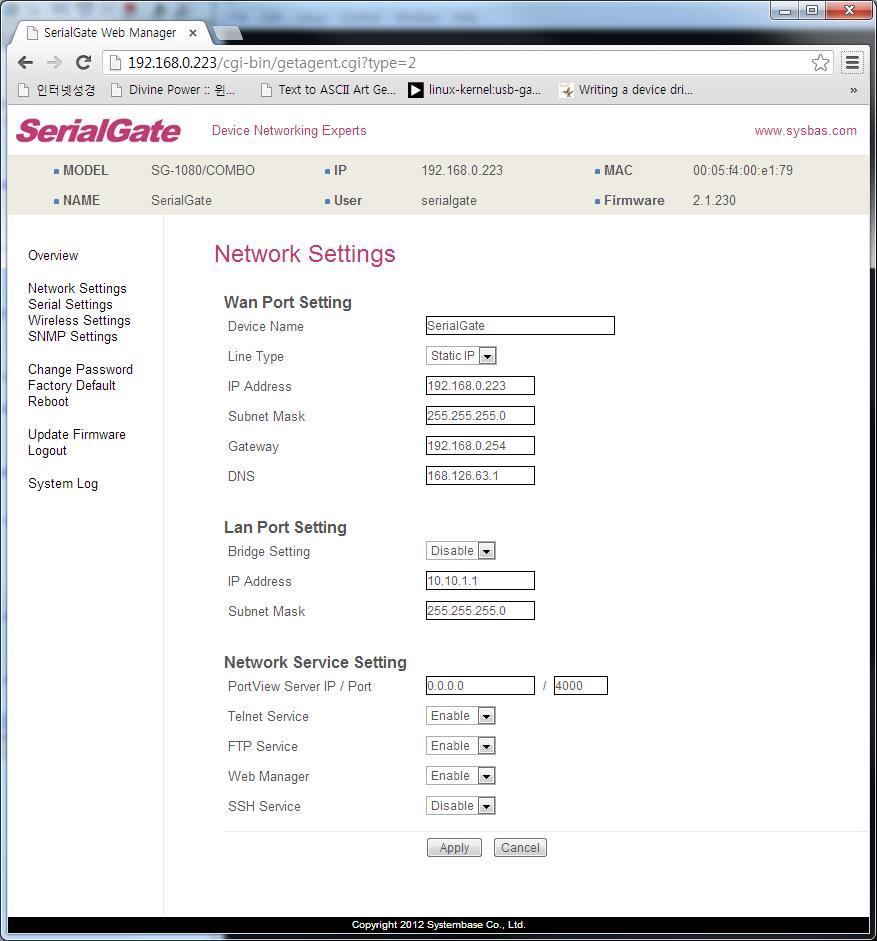
60 SG-1040/1080/
61 The followings are main features of WAN Configuration. Menu Default Description Device Name SerialGate Name of the current device Line Type Static IP IP obtaining method for SerialGate s network connection. IP Address Subnet Mask Gateway Current IP address SerialGate is assigned to. (When line type is Static IP, manually enter an appropriate IP address. When line type is DHCP, current IP is displayed, but it is not editable.) Current subnet mask SerialGate is assigned to. (When line type is Static IP, manually enter an appropriate subnet mask. When line type is DHCP, current subnet mask is displayed, but it is not editable.) Current default gateway SerialGate is assigned to (When line type is Static IP, manually enter an appropriate default gateway. When line type is DHCP, current default gateway is displayed, but it is not editable.).. DNS Domain Name Service IP address For SG-1040/1080/1160, the main features of LAN Configuration are as follows. Menu Default Description Bridge Disable Enable or Disable Bridge Mode IP Address Set the current IP address (Bridge : disable only) Subnet Mask Set Subnet Mask address (Bridge : enable only) Bridge 모드를사용할경우, LAN port와 WAN 포트의구분이없어지게되며 LAN 포트를다른시 리얼게이트와연결하는 daisy chain 방식으로네트웍을구성할수있다. 61
62 Main features for Network Service Configuration are as follows. Menu Default Descriptions PortView IP / Port Telnet Service FTP Service WEB Service SSH Service / 4000 Enable Enable Enable Disable Set the IP address and the socket number of the PC where Portview is installed. For more information about Portview, please refer to the Portview User Manual. If IP is set to , this feature is disabled Enable or disable Telnet service. If disabled, you cannot connect to SerialGate via Telnet. Enable or disable FTP service. If disabled, you cannot connect to SerialGate via FTP. Enable or disable Web service. If disabled, you cannot connect to SerialGate via Web. Enable or disable Secure Shell service. 62
63 Serial Settings (400MHz Model) A user can set the communication and operation environment for the serial port. After changing values, you need to click Apply button. If you don t want to change, you need to click Cancel button. 63
64 Serial settings for SerialGate are as follows. Menu Default Descriptions Select the operation protocol that will be applied in the serial port. Operation Mode COM Disable Disable the serial port. COM Redirector Use the serial port of SerialGate as a virtual COM port in Windows 2000/XP/2003/Vista. TCP Server SerialGate works as a socket server, waiting for the client connection on the network. Socket number for awaiting connections can be set in Local socket port field. After socket connection, data between socket and serial port will be transmitted. TCP Client SerialGate acts as a socket client in this mode. It tries to connect to the server IP address and the socket number assigned when a certain server waits for connection on the network. All data between the socket and the serial port is transferred untouched after the socket connection is established. TCP Broadcast SerialGate works as a server, accepting up to 5 simultaneous connections from socket clients. Data transmitted from SerialGate is broadcast to each socket client. TCP Multiplex SerialGate works as a server, accepting up to 5 simultaneous connections from socket clients. The difference between TCP Broadcast and TCP Multiplex is that Multiplex allows each socket to communicate exclusively. That is, serial data in response are only transferred to the sender socket. UDP Server SerialGate works as a UDP server, waiting for UDP connection from the client on the network. Socket number for awaiting connections can be set in Local socket port field. 64
65 Menu Default Descriptions Interface Local Socket Port RS232, RS422 RS Once a UDP packet is received to the socket that waits for the connection, the data is transmitted to the serial port. The data input from the serial port is put into UDP packets, which eventually are sent to the client. UDP Client When the data is input to the serial port, UDP packets are sent using the preset IP address and the socket number of the server. Pair_Master/ Pair_Slave It extends a serial cable between DTE and DCE to network, and enables communication not limited to distance. Two devices are required for this feature and set one to Pair_master and another to Pair_Slave. It can be used for serial communication tunneling. MODBUS ASCII Connect MODBUS/ASCII SLAVE using serial port and make user of MODBUS/TCP MASTER feature using LAN port in PC. This feature enables MODBUS media converter function. MODBUS RTU Connect MODBUS/RTU SLAVE using serial port and make user of MODBUS/TCP MASTER feature using LAN port in PC. This feature enables MODBUS media converter function. User Application A user can run own customized program. In order to run it, a user needs to ask for application development environment to SystemBase. RS232 model is set to RS-232. Combo model is selectable between RS-422, RS-485(No-Echo) and RS-485(Echo). Default value is RS-422. All model is selectable between RS-232, RS-422, RS-485(No-Echo) and RS-485(Echo). Default value is RS-232. SG-1160/ALL model is selectable between RS-232, RS-422, RS- 485(No-Echo) and RS-485(Echo). Default value is RS-232 and termination can be configured. Set the socket number for the port. TCP server and UDP server operation mode makes use of this port for awaiting network socket 65
66 Menu Default Descriptions connections. Port Alias Port1 Name each port for convenience. 16 Characters at maximum. Baud Rate 9600 bps Data Bits 8 Stop Bits 1 Parity None Flow Control None Device Type DataOnly Remote IP / Address / 4000 Port Set communication speed. (Options: 150, 300, 600, 1200, 2400, 4800, 9600, 19200, 38400, 57600, , , , bps) Set the number of bits in each character size. (Options: 5, 6, 7, 8) Set the number of stop bits.. (Options: 1, 2) Set parity bit check scheme.. (Options: None, Odd, Even) Set the flow control scheme. (Options: None, Xon/Xoff, RTS/CTS) Set the signal line checking method for the device to be connected to the given serial port. If the mode is set to Data Only, only TxD, RxD, and GND signal lines are used in inter-device communication. If the mode is set to Modem Signals, all modem signals except RI(Ring Indicator) are asserted, tested, and used in communication. (Options: Data Only, Modem Signals) If the Operation Mode is in TCP Client or UDP Client or Pair_Master mode, set the IP address and the socket number to connect to. 66
67 Menu Default Descriptions After a certain amount of time passes without any communication after the socket connection between the given serial port and the server is established, automatically disconnect the socket connection. Valid from 0 to sec. Keepalive Check Time 0 For example, if the operation mode is set to TCP Server and Alive Check Time is configured to 10, TCP Server will listen for the client s connection and eventually establish a connection. Since the check time is 10 seconds, the server will wait for 10 seconds until the client connected to it sends any packet. If there is no data for 10 seconds, server will quit the connection and return to the listening state. This option is helpful in preventing communication obstacles that occur when either SerialGate or the client quits unexpectedly (i.e. Sudden black out, reboot, LAN cable cut, etc.). In these cases, the other part of communication might not recognize the failure of its partner. Such misunderstanding can cause communication errors. If the value is set to 0, this function is disabled. Once connected socket will be retained until explicitly disconnected. (Only applies to TCP Client, TCP Server, TCP Broadcast, and TCP Multiplex operation modes.) Latency Time 0 This needs to be set when consecutive data from the given serial port needs to be transmitted to socket at once. For example, if 100 bytes of character string are to be transmitted from the serial device to a server through SerialGate, bypass is set to 0 for the latency time. Although it provides immediate sending through SerialGate, the server could be received a lot parts of divided packets. If the latency time is not 0, SerialGate will wait for the time and check new data. If there is new data, SerialGate repeatedly wait for the time. Otherwise, SerialGate will transfer the buffered data, but it could not run in real time. 67
68 Menu Default Descriptions Port Login Passive Username Passive Password Disable serialgate When the Operation Mode is set to TCP Server, ask for the username and password when the client tries to connect (Options: Enable, Disable) When the Operation Mode is set to TCP Server, set the username to ask for. 16 Characters at maximum. When the Operation Mode is set as TCP Server, set the password to ask for. 16 Characters at maximum. 68
69 Wireless Settings (400MHz Model) Only for SG-1010w/ALL & SG-1020w/ALL A user can set the wireless network parameters. After changing values, you need to click Apply button. If you don t want to change, you need to click Cancel button. If you use the same network between LAN and WIFI, This environment is not working normally. And so when you use the WiFi, you only use the LAN for configuration. 69
70 Menu Default Description Wireless Network Wireless Mode Wireless Network Name (SSID) Channel Disable Infrastructure none Auto When enabled, WiFi is available. Disable: WiFi is not available. Enable: WiFi is available. Set the wireless LAN mode. (Option: Infrastructure, Ad-Hoc) Infrastructure: Use WiFi under the Infrastructure mode. This mode is used for connecting to the wireless AP (Access Point) as a client to connect to other network. Ad-Hoc: Use WiFi under the Ad-hoc mode. This mode is used for 1:1 communication with another Ad-hoc client. Sets the identification (SSID) of a wireless network to be connected. (Case sensitive & Up to 32 bytes using alphabets and numbers) SSID should be same for all devices on the same wireless network. Selects a frequency channel for wireless connection. (Option: Auto, 1 ~ 13) Auto: Connect a channel specified in AP automatically. In most cases, this setting is used. Value Specification: Specify a channel to be connected manually. Sets the speed for wireless connection. (Option: Auto, 1, 2, 5.5, 6, 9, 11, 12, 18, 24, 36, 48, 54Mbps) Bitrate Auto Auto setting adjusts the speed depending on signal sensitivity and noise. In most cases, this setting is used. If Wireless Network mode is set to b/g Mixed, all options can be selected b only allows setting as 1, 2, 5.5 and 11Mbps g only allows setting as 6, 9, 12, 18, 24, 36, 48 and 54Mbps. If the setting is in low communication speed, it provides 70
71 Fragment Threshold Authentication Mode Encryption Type 2346 AUTO NONE more stable communication in an environment with a lot of noise. Contrary to this, high communication speed setting has higher risk of data loss in an environment with a lot of noise. Sets the maximum packet size to send a packet after dividing into small pieces. (Range: 256 ~ 2346 bytes) Communication overhead is increased but communication error can be reduced in serious interference or noise environment. In most cases, this setting is not used. This feature will be disabled if 2346 is configured. (Option: AUTO, OPEN, SHARED, WPAPSK, WPA2PSK) An authentication mode defines the procedure that the device uses when it associates with an access point. AUTO: Specifies IEEE Auto System authentication. OPEN: Specifies IEEE Open System authentication. SHARED: Specifies IEEE Shared Key authentication that uses a preshared WEP key. WPA-PSK: Specifies WPA security. Authentication is performed between the supplicant and authenticator over IEEE 802.1X. Encryption keys are dynamic and are derived through the preshared key used by the supplicant and authenticator. WPA2-PSK: Specifies WPA2 security. Authentication is performed between the supplicant and authenticator over IEEE 802 1X. Encryption keys are dynamic and are derived through the preshared key used by the supplicant and authenticator. (Option: NONE, WEP, TKIP, AES) Encryption modes define the set of cipher suites that can be enabled on the device. NONE: Encryption not used. WEP: Wired Equivalent Privacy (WEP) is the RC4-71
72 based algorithm specified in the IEEE specification. TKIP: Temporal Key Integrity Protocol (TKIP) is the RC4-based cipher suite based on the algorithms defined in the WPA and IEEE i specifications. AES: The Advanced Encryption Standard (AES) defines an encryption algorithm in FIPS PUB 197. Network Key none Type in Key value by Encryption Type. Connection Type DHCP IP Address Subnet Mask Gateway DNS Sets an IP address type in a wireless network. (Option: DHCP, Static IP) DHCP: Assign a dynamic IP address through a DHCP server. Static IP: Specify an IP address manually. Sets an IP address of a wireless network. If the line Type is Static IP, a user can enter an IP address directly. If line type is DHCP, the current IP address is displayed. In DHCP type, the address cannot be changed. Sets Subnet Mask of a wireless network. If the line Type is Static IP, a user can enter a subnet mask address directly. If line type is DHCP, the current subnet mask address is displayed. In DHCP type, the address cannot be changed. Sets a gateway address of a wireless network. If the line Type is Static IP, a user can enter a gateway address directly. If line type is DHCP, the current gateway address is displayed. In DHCP type, the address cannot be changed. Sets a DNS server address of a wireless network. If the line Type is Static IP, a user can enter a DNS server address directly. If line type is DHCP, the current DNS server address is displayed. In DHCP type, the address cannot be changed. 72
73 SNMP Settings (400MHz Model) A user can set the communication and operation environment for the SNMP Agent. After changing values, you need to click Apply button. If you don t want to change, you need to click Cancel button. 73
74 Menu Default Descriptions SNMP v1/v2/v3 Agent V1/2 Attribution V3 Attribution V3 Username/ Password TRAP IP/ Port System reset notification Port connect notification Port disconnect notification Disable ReadOnly ReadOnly serialgate /administr ator /16 2 Enable Disable Disable Enable or disable Simple Network Management Protocol (SNMP) support. (Options : Disable/Enable) SNMP V1/2 Attributes can read and write by SNMP Agent. In order to read attributes only, change the feature to "ReadOnly". In order to read and write attributes, change the feature to "ReadWrite". (Options : ReadOnly/ ReadWrite) SNMP V3 Attributes can read and write by SNMP Agent. In order to read attributes only, change the feature to "ReadOnly". In order to read and write attributes, change the feature to "ReadWrite". (Options : ReadOnly/ ReadWrite) Configure the Username and the password when use SNMP V3. The Password is at least 8 character string Configure the server IP address and Port which receive the TRAP information. If Enable is selected, notify the System reset info. (Option : Enable, Disable) If Enable is selected, notify the Serial Port opened info. (Option : Enable, Disable) If Enable is selected, notify the Serial Port Closed info. (Option : Enable, Disable) 74
75 Change Password (400MHz Model) Change username and password for an access to Web and Telnet. After changing values, you need to click Apply button. If you don t want to change, you need to click Cancel button. In case that a user forgot password, press Reset button for less than 3 seconds to restore the settings back to factory default. However, please be aware that all other settings will be initialized and back to factory default. Default user id : serialgate Default password :

76 Update Firmware (400MHz Model) Firmware is an application embedded in Flash memory of SerialGate. Set the location of the firmware file to update, using the Browse button. The selected firmware will be transferred to SerialGate when you click Start Update. After the transmission is complete, SerialGate will be automatically restarted to operate with the new firmware. Then your browser is reloaded on the login page. 76
77 Factory Default (400MHz Model) Restore all the configuration parameters to the factory default values. Clicking on Factory Default button will delete all current settings and restore settings to the initial status, and SerialGate will automatically reboot. SG-1010, 1020, 1010(W)/ALL, 1020(W)/ALL : LAN Default IP Address , SG-1040, 1080, 1160 : WAN Default IP Address , LAN Default IP Address If Factory Default is complete, it shows the initialized IP address, username and password as below, and restarts the device. 77
78 Reboot (400MHz Model) This menu provides the reboot function via web. After reboot, your browser is reloaded on the login page. 78

79 System Log (400MHz Model) This feature confirms SerialGate s system log information. (Only available for SG-1040/1080/1160) It records system startup and shutdown time, ending time of each port connection, configuration and so on. C:\>telnet SerialGate Login : serialgate Password : #test_rtc -s #test_rtc -g Get ioctl RTC Time = , 15:00:05 #reboot Set Current time (Year, Month, Date, Hour, minute, second) setting time Shows time elapsed 79
80 Ch6 Configuration via Telnet Connection Open your telnet client program and enter SerialGate s IP address to connect. You need to enter appropriate username and password to login. Please note that this username and password is used as authentication method for Web as well. This means if username or/and password has been modified from the telnet interface, modified values have to be entered to connect to web, and vice versa. Factory default username : serialgate Factory default password : [def] commands - you can configure SerialGate s settings. [def help] commands - you can view current SerialGate s settings. After changing values, you can see modified values with set view commands. But, be careful because these values are not in effect unless you issue a def save command. Changes will be discarded if you do not save current settings. 80
81 View Commands Commands related to View are as follows. Command def view def view wan def view management def view serial def help Description Show all information about SerialGate Show WAN network settings Show managing items settings Show serial port settings Show command list and help Network Commands Commands related to configuration of general network environment and network management are as follows. Command Default Description def mac <Mac Address> def line [ip/dhcp] def ip <IP Address> def mask <Subnet mask> def gateway <Gateway address> 00:05:f4:00:20:57 Static IP Register SerialGate s MAC address IP obtaining method for SerialGate s network connection Display the current IP address If line type is Static IP, manually enter an appropriate IP address. If line type is DHCP, it is not editable. Instead, current IP address is shown. Display the current subnet mask address If line type is Static IP, manually enter an appropriate subnet mask address. If line type is DHCP, it is not editable. Instead, current subnet mask address is shown Display the current Gateway address If line type is Static IP, manually enter an appropriate Gateway address. If line type is DHCP, it is not editable. Instead, current 81
82 Gateway address is shown def dns <IP Address> def portviewip <IP address> def portviewport <Port number> def ftp [enable/ disable] def telnet [enable/ disable] def web [enable/ disable] def ssh [enable/ disable] def name [SerialGate name] def snmp [enable/ disable] def v1readwrite [enable, disable] def v3readwrite [enable, disable] Set IP address of Domain Name Service Configures IP of PC which Portview is installed If IP is set to , Portview feature is disabled (Please refer to Portview User Manual in SerialGate Utility & Documents CD for detailed information.) 4000 Set the socket number of a PC which Portview is installed. Enable or disable FTP service. Enable If disabled, you cannot connect to SerialGate via FTP. Enable or disable Telnet service. Enable If disabled, you cannot connect to SerialGate via Telnet. Enable or disable Web service. Enable If disabled, you cannot connect to SerialGate via Web. Enable or disable SSH service. Disable If enabled, you can connect to SerialGate via SSH. Product Name Set the name of SerialGate. (Max 32 bytes) Enable or disable SNMP(Simple Network Management Protocol) Disable - MIB-II(RFC 1213): System, Interface, IP, ICMP, TCP, UDP - MIB-I (RFC 1317): Serial Interface SNMP V1/2 Attributes can read and write by SNMP Agent. In order to read attributes only, change the feature to "ReadOnly. Disable In order to read and write attributes change the feature to "ReadWrite. (Options : ReadOnly/ ReadWrite) SNMP V3 Attributes can read and write by SNMP Agent. In order to read attributes only change the feature to Disable "ReadOnly. In order to read and write attributes change the feature to "ReadWrite. 82
83 (Options : ReadOnly/ ReadWrite) def v3username [string] def v3password [string] def trapip [address] def trapoprt [Socket No.] def trap_reset [enable, disable] def trap_connect [enable, disable] def trap_disconnect [enable, disable] serialgate Configure the Username to use SNMP V3. none Configure the password to use SNMP V3. Configure the server IP address which transmits the TRAP information. Configure the server Port which transmits the TRAP 162 information. Enable If Enable is selected, inform the "System reset info". Disable If Enable is selected, inform the "Serial Port opened info". Disable If Enable is selected, inform the "Serial Port Closed info". Serial Commands You can set the communication and operation environment for serial port. Please refer to Chapter 5 for details of each option. Commands Default Description def port x protocol [disable, com_redirect, tcp_server, Tcp_client, tcp_broadcast, Tcp_multiplex, udp_server, udp_client, pair_master, pair_slave, modbus, user] com Select the operation protocol to be used in serial port. 83
84 Commands Default Description def port x interface [rs232, rs422, rs485ne, rs485e] def port x socket <port number> def port x name <name> def port x speed [150/300/600/1200/2 400/4800/9600/1920 0/38400/57600/ /230400/460800/ ] def port x data [5 / 6 / 7 / 8] def port x stop [1 / 2] Configure interface of serial port. It is not available for RS232 model. RS232, Combo model can choose from RS-422, RS-485-No-Echo RS422 and RS-485-Echo. SG-1160/ALL can choose from RS-232, RS-422 and RS Set the socket number for the port. Com_redirect, TCP Server, TCP Multiplex, TCP Broadcast, UDP Server, 4001 Pair_Slave modes make use of this port for awaiting network socket connections. Name each port for convenience. 16 Characters at Port 1 maximum 9600bps Set communication speed. 8 Set the number of bits in each character size. 1 Set the number of stop bits. def port x parity [none/odd/even] def port x flow [none/xon/rts] def port x signal [data/modem] def port x remote <IP address> def port 1 remoteport <socket number> none none data Set parity bit check scheme. Set the flow control scheme. Set the signal line checking method for the device to be connected to the given serial port. Set IP address of the server to be connected in TCP Client, UDP Client, Pair_Master mode. Set the socket number to connect to when the Operation Mode is set to TCP Client or UDP Client or Pair_Master mode. 84
85 Commands Default Description def port x keepalive <0 ~ 65535> def port x latency <msec> def port x login <Enable/Disable> def port x loginname <username> def port x loginpass <password> def port x termination <Enable/Disable> 0 0 Disable None None Disable After a certain amount of time passes without any communication after the socket connection between the given serial port and the server is established, automatically disconnect the socket connection. This needs to be set when consecutive data from the given serial port needs to be transmitted to socket at once. When the Operation Mode is set to TCP Server, ask for the username and password when the client tries to connect. When the Operation Mode is set to TCP Server, set the username to ask for(max 8 bytes) When the Operation Mode is set as TCP Server, set the password to ask for( Max 8 bytes) Set termination for each port. (only SG-1160 Model) 85
86 Username/Password Commands Configure username and password for Web/Telnet/FTP. Commands Default Descriptions def username <username> def password <password> serialgate Set username to use in Web, Telnet, or FTP. 16 Characters at maximum. Set password to use in Web, Telnet, or FTP. 16 Characters at maximum. System Commands Commands def default def apply Descriptions Restore all settings to factory default. Requires reboot for changes to take effect. Save and apply changed configuration settings. Reboot Reboot Serialgate. 86
87 Ch7 Configuration via LCD This feature is only for SG-1160/ALL model. A user of SG-1010/1020/1040/1080 does not need to read this chapter. Through the LCD on the front panel, a user is able to test operation of each interface and configuration. By default, the LCD displays communication status of each port, and by operating the keys next to the LCD, the interface can be tested. LCD and Key Operation Port Status ESC Enter Graphic LCD is 16 Character * 2 Line, and four keys are to configure the operating environment. The function of each key is as follows. Key Function 1 Function 2 ESC Enter Go to the top menu. Select the current value, and then go to the next menu Previous menu/item Next menu/item If the variable is numeric, it increases the value Ex.) If the variable is numeric, move to the next space Ex.)
88 Main Menu Default screen of graphic LCD displays the status of each port. Press ESC to go back to the main menu screen. Main menu items are as follows. Network Setup : Change the network configuration of device server. Port Setup : Change the operating environment setting for each port. Status : Check the connection status of the port and device server s version information. System : Perform firmware upgrade or reset, and initialization. Verification : Verify each interface HW of device server. 88
89 Network Setup Change the network configuration of device server. In order to select Network Setup, press ESC on the panel until Main Menu comes up, and if Main Manu is displayed, press << or >> until you see Network Setup. Then, press Enter to change the details. At anytime ESC is selected, it moves to the top menu and asks if a user wants to save the change in Flash memory in case of a change made. For more details about each menu, please refer to Chapter 5 Configuration via Web and Chapter 6 Configuration via Telnet. Menu and selectable options are as follows. Menu Option Default Description <<, >> : Select option Static IP, DCHP Network line Static IP Enter : Save the current option, and go to Client the next menu. IP Address <<: Increase the value of the cursor Subnet Mask position. Gateway >>: Move cursor to the next space. Enter : Save the current option, and go to the next menu. FTP Service Enable, Disable Enable Telnet Service Enable, Disable Enable SSH Service Enable, Disable Disable WEB Service Enable, Disable Enable PortView Address <<, >> : Select option Enter : Save the current option, and go to the next menu. <<: Increase the value of the cursor position. >>: Move cursor to the next space. Enter : Save the current option, and go to the next menu. 89
90 Port Setup Change the operating environment setting for each port. In order to select Port Setup, press ESC on the panel until Main Menu comes up, and if Main Manu is displayed, press << or >> until you see Port Setup. Then, press Enter to change the details. At anytime ESC is selected, it moves to the top menu and asks if a user wants to save the change in Flash memory in case of a change made. For more details about each menu, please refer to Chapter 5 Configuration via Web and Chapter 6 Configuration via Telnet. Menu and selectable options are as follows. Menu Option Default Description Protocol Disable Com_redirector TCP_Server TCP_Client TCP_Broadcast TCP_Multiplex UDP_Server UDP_Client Pair_Master Pair_Slave Com_Redirector Socket No ~ Port number RS232, Interface RS422 RS485 (NE) RS232 RS485(E) Device Type Data Only, Modem Data Only BaudRate 150 ~ bps 9600 <<, >> : Select option Enter: Save the current option, and go to the next menu. <<: Increase the value of the cursor position. >>: Move cursor to the next space. Enter : Save the current option, and go to the next menu. <<, >> : Select option Enter: Save the current option, and go to the next menu. Parity None, Odd, Even None Data Bits 5 ~
91 Stop Bits 1, 2 1 Latency_time 0 ~ <<: Increase the value of the cursor Keepalive 0 ~ position. Remote IP >>: Move cursor to the next space. Enter: Save the current option, and go to Remote Port 4000 the next menu. Termination Enable, Disable Disable <<, >> : Select option Enter: Save the current option, and go to the next menu. Status Check the connection status of the port and device server s version information In order to select Status, press ESC on the panel until Main Menu comes up, and if Main Manu is displayed, press << or >> until you see Status. Then, press Enter to change the details. At anytime ESC is selected, it moves to the top menu. Menu Display Description Version L10b, K10a, F10a Port Status B : Boot_loader Version O : OS Version F : Firmware Version If serial port is in communication, the port number is displayed on the corresponding space. Since it only shows one digit, it will only display the second digit for 10~16 port. 91
92 System Update device server firmware, initialize the system or command port reset. In order to select System, press ESC on the panel until Main Menu comes up, and if Main Manu is displayed, press << or >> until you see System. Then, press Enter to change the details. At any time ESC is selected, it moves to the top menu. Menu Option Default Description Port Reset Factory Default Reboot System Firmware Update Cancel Yes Cancel <<, >> : Select option. Enter : If Cancel is selected, it moves to the next menu. If Yes is selected, that action is performed. Port Reset If yes is selected in Port Reset, LCD displays the port number from 1 to 16 as below, and the cursor is at the first one. P o r t R e s e t Move the cursor to the port to be reset using <<, >> keys and press Enter. Then, the corresponding port will be reset. Factory Default Cancel and Yes are selectable with <<, >> keys. If a user selects Yes and Enter in turn, configuration resets to the factory default. Reboot System Cancel and Yes are selectable with <<, >> keys. If a user selects Yes and Enter in turn, it prints out Now Rebooting message and reboots the device server. Firmware update Update device server s firmware. (OS, Filesystem) In order to perform this feature, TFTP server and firmware image files should be prepared in PC. 92
93 Cancel and Yes are selectable with <<, >> keys. If a user selects Yes and Enter in turn, it starts device server firmware update. First, register the name of firmware to be updated in PC. Firmware name by default is the filesystem firmware name showing on the display. F i r m w a r e N a m e s g f s 1 0 a. b i n Using >> key, move the cursor to the string that a user would like to modify and change the value with << key. After registration of firmware name is complete, press Enter. Then, a user can input the IP address of a PC that has TFTP server. T F T P I P A d d r e s s Default IP address is , and using >> key, a user can move the cursor to the IP address value to be changed. Using << key, a user can change the value. After changing the IP address, if a user selects Enter, device server connects to the TFTP address, downloads the firmware file, and starts updating. If the update fails, it prints out Download Failed message. In this case, a user has to make sure if the registered firmware image s name and TFTP server s IP address are correct. Also, check if TFTP server is running and there is a firmware in PC. If the update is successfully complete, reset the device server power and operate it in a new firmware. 93
94 Verification It verifies each interface HW of a device server. In order to select System, press ESC on the panel until Main Menu comes up, and if Main Manu is displayed, press << or >> until you see Verification. Then, press Enter to change the details. At anytime ESC is selected, it moves to the top menu. (*) When a user performs this test, all the program running in a device server stops. So, a user must restart the device server after the test. Menu Option Default Description RS232(Loopback) RS232(Signal) RS422(Loopback) RS485(Loopback) Testing WAN Port Testing LAN Port Testing MMC Cancel Yes Cancel <<, >> : Select option. Enter : If Cancel selected, go to the next menu. If Yes selected, that action is performed. Testing Reset Testing Console Testing RTC RS232 (Loopback) Change all the serial ports of a device server to RS-232, and conduct a Loopback test. RS-232 Loopback connector must be connected to all the serial ports for the test. If a user selects yes option, it starts Loopback test and prints out the result on LCD. T e s t I n g ( R S ) O O O O O O O O O O O O O O O O If there is nothing wrong, it displays O or X otherwise. 94
95 RS232 (Seinal) Change all the serial ports of a device server to RS-232, and conduct a serial signal test. RS-232 Loopback connector must be connected to all the serial ports for the test. If a user selects yes option, it starts serial signal test and prints out the result on LCD. T e s t I n g ( S I g n a l ) O O O O O O O O O O O O O O O O If there is nothing wrong, it displays O or X otherwise. RS422 (Loopback) Change all the serial ports of a device server to RS-422, and conduct a Loopback test. RS-422 Loopback connector must be connected to all the serial ports for the test. If a user selects yes option, it starts Loopback test and prints out the result on LCD. T e s t I n g ( R S ) O O O O O O O O O O O O O O O O If there is nothing wrong, it displays O or X otherwise. RS485 (Loopback) Change all the serial ports of a device server to RS-485, and conduct a Loopback test. No additional loopback connector is required for RS-485 since RS-485 supports self Loopback. If a user selects yes option, it starts Loopback test and prints out the result on LCD. T e s t I n g ( R S ) O O O O O O O O O O O O O O O O If there is nothing wrong, it displays O or X otherwise. 95
96 Testing WAN Port Test WAN port of a device server. For the test, WAN port must be connected to network, and there should be a PC with the IP address, for the Ping test on network. If a user selects yes option, it tries Ping to , and prints out the result on LCD. T e s t I n g W A N P o r t OK! If there is nothing wrong, it shows OK! or Failed! otherwise. Testing LAN Port Test LAN port of a device server. For the test, LAN port must be connected to network, and there should be a PC with the IP address, for the Ping test on network. If a user selects yes option, it tries Ping to , and prints out the result on LCD. T e s t I n g L A N P o r t OK! If there is nothing wrong, it shows OK! or Failed! otherwise. Testing MMC It tests whether memory card of a device server can read and write. For the test, SD card must be inserted to the device server. If a user selects yes option, it reads and writes the data on SD card, and prints out the result on LCD. T e s t I n g M M C OK! If there is nothing wrong, it shows OK! or Failed! otherwise. 96
97 Testing Reset It tests whether Reset button of a device server works. If a user selects yes option, it waits for Reset key to be pressed for approximately 6 seconds. If Reset is pressed or 6 seconds passed, it shows the result on LCD. T e s t I n g R e s e t OK! If there is nothing wrong, it shows OK! or Failed! otherwise. Testing Console It tests whether console port of a device server works. For the test, DB9 Loopback connector should be conned to all the console ports. If a user selects yes option, it starts Loopback test, and prints out the result on LCD. T e s t I n g C o n s o l e OK! If there is nothing wrong, it shows OK! or Failed! otherwise. Testing RTC It tests RTC interface working as a clock for the device. If a user selects yes option, it sets time up on RTC and prints out the result on LCD. After the test, a user should reset the time and date. T e s t I n g R T C O K! If there is nothing wrong, it shows OK! or Failed! otherwise. 97


98 Ch8 Application SerialGate can be used in many practical applications in various fields. Here we present some of them. Com Port Redirector With COM Port Redirection, a user can use serial port connected to SerialGate on the network as if it is a serial port on PC. Install Com Port Redirector and set the following steps. (For installation, please refer to Com Port Redirector manual enclosed in CD. In the picture below, IP address of SerialGate is , and the first serial port is being used. A user can open Com1 and use serial device connected to SerialGate. 98

99 In order to correspond to the Redirector setting of PC, change the setting in the first serial port of SerialGate as follows. 99

100 TCP_Server (TCP/IP connection from PC to SerialGate) In PC s socket program, connect the first serial port of SerialGate. Since socket number for the first port of SerialGate is default 4001, try to connect to SerialGate s IP address and socket number 4001 when connecting from a PC to SerialGate. As shown below, change the Operation Mode to TCP_Server and confirm the socket number waiting for connection.. Check the communication speed of a serial device to be connected to serial port, and set it to Com Specification. 100
101 TCP_Client (TCP/IP Connection: SerialGate PC) Since it is a connection from SerialGate to a PC, change the Operation Mode to TCP_Client and register PC s IP address and socket number to be connected. Check the communication speed of a serial device to be connected to serial port, and set it to Com Specification. 101

102 Pair (Serial Line To Serial Line) This structure is mainly used when the cable length between PC and serial device is short so a user needs to extend the communication distance. This approach consists of two SerialGates connected in Pair. Setting for SerialGate 1 In order to perform Master features, change Operation Mode to Pari_Master. Check the communication speed of a PC and set it in Com Specification, and also register Slave SerialGate s IP address and port number in Remote IP/Port. 102
Eddy-CPU User Guide. English Ver 0.9. March 23, 2007
 Eddy-CPU User Guide English Ver 0.9 March 23, 2007 Revision History Revision Date Document Version Pages Description March 20, 2007 1.0 All Initial release by jhkim Copyright 2007 SystemBase Co., Ltd.
Industrial Serial Device Server
 1. Quick Start Guide This quick start guide describes how to install and use the Industrial Serial Device Server. Capable of operating at temperature extremes of -10 C to +60 C, this is the Serial Device
NCOM SERIAL DEVICE SERVER 1XX SERIES USER S MANUAL
 NCOM SERIAL DEVICE SERVER 1XX SERIES USER S MANUAL 2017-07-07 Edition Titan Electronics Inc. Web: www.titan.tw Contents 1. INTRODUCTION... 4 1.1 Key Features... 5 1.2 Specifications... 6 2. PANEL LAYOUT
HOME AUTOMATION, INC. Model 93A00-1. Serial Server. User s Manual
 HOME AUTOMATION, INC. Model 93A00-1 Serial Server User s Manual Document Number 93I00-1 Rev. A December, 2009 Introduction The 93A00-1 is a RS232/RS485 to TCP/IP converter integrated with a robust system
NCOM SERIAL DEVICE SERVER 4XX SERIES USER S MANUAL
 NCOM SERIAL DEVICE SERVER 4XX SERIES USER S MANUAL 2017-07-07 Edition Titan Electronics Inc. Web: www.titan.tw Contents 1. INTRODUCTION... 4 1.1 Key Features... 5 1.2 Specifications... 6 2. PANEL LAYOUT
USER S MANUAL. PH232Ex1. #1 RS-232 Serial Port to Ethernet, Terminal Server/Client. Doc No: PH232Ex1-UM-001 IPEX. (IP Electronix)
") USER S MANUAL PH232Ex1 Doc No: PH232Ex1-UM-001 #1 RS-232 Serial Port to Ethernet, Terminal Server/Client IPEX (IP Electronix) Contents 1. INTRODUCTION... 3 2. SPECIFICATIONS... 3 3. PACKAGE CHECKLIST...
USER S MANUAL PH232Ex1 Doc No: PH232Ex1-UM-001 #1 RS-232 Serial Port to Ethernet, Terminal Server/Client IPEX (IP Electronix) Contents 1. INTRODUCTION... 3 2. SPECIFICATIONS... 3 3. PACKAGE CHECKLIST...
NET101. RS232 / RS422 / RS485 to Ethernet Converter. User s Manual. Version 1.2
 NET101 RS232 / RS422 / RS485 to Ethernet Converter User s Manual Version 1.2 Copyright Information Copyright 2004-2005, Mega System Technologies, Inc. All rights reserved. Reproduction without permission
Lantech LSC-1102B SERIAL TO TCPIP CONVERTER. User Manual
 Lantech LSC-1102B SERIAL TO TCPIP CONVERTER User Manual V1.0 Sep 2016 Table of Contents 1. Introduction 3 Overview 4 Product Specifications 8 2. Description & Installation 10 Product Panel Views 10 LED
Document Name: User Manual for SC10MK, Modbus RTU to Modbus TCP Converter
 Document Name: User Manual for SC10MK, Modbus RTU to Modbus TCP Converter Login for the first time, please use http://192.168.1.100 To key in user name and password is for identifying authorization. Default
User Manual A08. User Manual
 A08 TABLE OF CONTENTS TABLE OF CONTENTS... 1 1. INTRODUCTION... 2 1.1. Key Features... 3 1.2. OS Requirement... 4 1.3. Specification... 4 1.4. Packing List... 4 2. OVERVIEW... 5 2.1. LED Definition...
RS-232/422/485 to Copper or Fiber. Ethernet Converter. User s Manual
 RS-232/422/485 to Copper or Fiber Ethernet Converter User s Manual Table Of Contents TABLE OF CONTENTS... 1 INTRODUCTION... 3 PRODUCT OVERVIEW... 3 PRODUCT FEATURES... 3 PACKING LIST... 4 LED INDICATORS...
Industrial Device Server IDS-3010 Fiber Series
 USER S MANUAL Industrial Device Server IDS-3010 Fiber Series Ver. 1.0, Jan. 2008 Table of Content Getting to Know Your Device Server... 3 1.1 About the IDS-3010 Serial Device Server... 3 1.2 Software Features...
RS232/RS485/RS422 to TCP/IP Converter ITEM NO.: RS007
 RS232/RS485/RS422 to TCP/IP Converter ITEM NO.: RS007 RS007 is a universal data converter which support serial RS232, RS422 and RS485 to the TCP / IP intelligent communication converter, it offers RS485/RS422
Embedded Device Server. White Paper. English ver 1.2
 Embedded Device Server White Paper English ver 1.2 February 5, 2007 Overview In the field of device networking, device servers have been playing a huge role in providing network connectivity for serial
Document Name: User Manual for SC10EK4 Serial to Ethernet Converter with 4 TCP Sockets. Index
 Document Name: User Manual for SC10EK4 Serial to Ethernet Converter with 4 TCP Sockets. Index Technical Specifications 1 Installation Procedure 1 LED Indications 2 Configuration Procedure Configuration
SERIAL TO ETHERNET CONVERTER E-P User Manual
 SERIAL TO ETHERNET CONVERTER E-P132-100 User Manual 1 Table of Contents Introduction... 4 Overview.. 5 Package Checklist 6 Block Diagram 7 Product Features...8 Product Specifications 9 Converter Description
TCP/IP Converter. EX-9132 Operation Manual for 8051 Series
 TCP/IP Converter EX-9132 Operation Manual for 8051 Series First Edition, March 2005 Table of Contents 1. Introduction 3 Overview 4 Package Checklist 5 Block Diagram 6 Features 7 Product Specifications
Tel: Fax:
 NP302 Series 2-port RS-232 232/485/422 to Ethernet Serial Server User manual Shenzhen 3onedata Technology Co.,Ltd Tel: +86-755-26702688 Fax: +86-755-26703485 www.3onedata.com Contents 1. Introduction...
MGate TM EIP3000 DF1 to EtherNet/IP Gateway User s Manual
 MGate TM EIP3000 DF1 to EtherNet/IP Gateway User s Manual First Edition, June 2009 www.moxa.com/product 2009 Moxa Inc. All rights reserved. Reproduction without permission is prohibited. MGate EIP3000
WM-120. Serial to Ethernet Module. Serial to Ethernet Module. User Manual. Version 1.0. Infosystem Technology Corporation, Ltd.
 W M - 1 2 0 User Manual Version 1.0 Infosystem Technology Corporation, Ltd. Index 1. Disclaimers... 1. A. Warranty... 2. B. Trademark... 2. 2. Product Information... 3. A. Introduction... 3. B. Features...
TRP-C37M User s Manual
 TRP-C37M User s Manual MODBUS TCP to RTU/ASCII Gateway Printed May. 2011 Rev 1.1 Trycom Technology Co., Ltd 1F, No.2-11, Sihu street, Yingge Township, Taipei, Taiwan ROC Tel: 886-2-86781191, Fax: 886-2-86781172
Ethernet Serial Server
 Ethernet Serial Server Users Manual Eport-101, Eport-102, Eport-104, Eport108 1 INTRODUCTION... 1 1.1 FEATURES... 1 1.2 PRODUCT SPECIFICATIONS... 2 1.3 DEFAULT SETTINGS... 3 2 COMMUNICATION MODES... 4
MGate MB3000 Modbus Gateway User Manual
 MGate MB3000 Modbus Gateway User Manual Sixth Edition, July 2012 www.moxa.com/product 2012 Moxa Inc. All rights reserved. MGate MB3000 Modbus Gateway User s Manual The software described in this manual
NetBiter Serial Server User Manual
 User Manual IntelliCom Innovation AB Linjegatan 3D SE-302 50 Halmstad SWEDEN Phone +46 35 18 21 70 Fax +46 35 17 29 09 email info@intellicom.se web www.intellicom.se Revision List Revision Date Author
DGH A3000 Configuration Guide For use with DGH Modules
 DGH A3000 Configuration Guide For use with DGH Modules Revision Date: 12/07/05 Version: 1.00 Contact Information: http://www.dghcorp.com Ph: (603) 622-0452 Fax: (603) 622-0487 Mailing Address: DGH Corporation
MGate MB3000 Modbus Gateway User s Manual
 User s Manual Seventh Edition, May 2013 www.moxa.com/product 2013 Moxa Inc. All rights reserved. User s Manual The software described in this manual is furnished under a license agreement and may be used
Operation Manual EX-9133C-2-MTCP
 Operation Manual EX-9133C-2-MTCP Modbus TCP to Modbus RTU/ASCII Converter Version 1.0.1 20th Oct. 2016 Page 0 Table of Contents 1. Introduction 3 Overview 4 Package Checklist 4 Block Diagram 5 Features
TRP-C37. Ethernet to RS232/422/485 Converter. User s Manual. Printed September Rev 1.6
 TRP-C37 Ethernet to RS232/422/485 Converter User s Manual Printed September 1 2015 Rev 1.6 Trycom Technology Co.,Ltd No.35, Zhongxing Rd., Guishan Township, Taoyuan County 333, Taiwan. Tel : 886-3-350-3351
e-net TCP/IP Converters
 e-net TCP/IP Converters E-P132 Operation Manual for 8051 Series First Edition, March 2005 Table of Contents 1. Introduction 3 Overview 4 Package Checklist 4 Block Diagram 5 Features 6 Product Specifications
IDS-141A/181A. Industrial 4-port/8-port slim type serial to Ethernet device server. Features. Introduction. DS-Tool
 4/8 Port v1.5 / Dec, 2011 Features 4-port/8-port slim type serial to Ethernet device server Operating Modes : Virtual Com, Tunnel, TCP Server, TCP Client, UDP Multiple host devices : 5 host devices: Virtual
Universal ipulse Ethernet Adapter. User Manual
 Universal ipulse Ethernet Adapter User Manual January 2011 Table of Contents Introduction 3 Overview 4 Package Checklist 4 Product Features 4 Product Specifications 6 IPulse-e Description & Installation
TRP-C37. Ethernet to RS232/422/485 Converter. User s Manual. Printed Apr.2014 Rev 1.3
 TRP-C37 Ethernet to RS232/422/485 Converter User s Manual Printed Apr.2014 Rev 1.3 Trycom Technology Co.,Ltd No.35, Zhongxing Rd., Guishan Township, Taoyuan County 333, Taiwan. Tel : 886-3-350-3351 Fax:
Operation Manual of EX9132CST-Series
 Operation of EX9132CST-Series Serial to TCP/IP Converter (EX9132CST-2/ EX9132CST-RS485/ EX9132C-RS232) Version 1.0.0. 30.03.2017 Table of Contents 1 Introduction... 4 2 Overview... 5 2. 1 Package Checklist...
TRP-C37M User s Manual
 TRP-C37M User s Manual MODBUS TCP to RTU/ASCII Gateway Printed OCT. 2010 Rev 1.0 Trycom Technology Co., Ltd 1F, No.2-11, Sihu street, Yingge Township, Taipei, Taiwan ROC Tel: 886-2-86781191, Fax: 886-2-86781172
TRP-C37 User s Manual
 TRP-C37 User s Manual Ethernet to RS232/422/485 Converter Printed Oct. 2010 Rev 1.0 Trycom Technology Co., Ltd 1F, No.2-11, Sihu street, Yingge Township, Taipei, Taiwan ROC Tel: 886-2-86781191, Fax: 886-2-86781172
Industrial Device Server User s Manual
 Industrial Device Server User s Manual IDS-5042 Series Version 1.00 Aug 2010. ORing Industrial Networking Corp. 4F., NO.3, Lane235, Baociao Rd.Sindian City, Taipei County 23145 Taiwan, R.O.C. Tel: + 886
LM300 Manager User Manual. Document Version: 1.1 LM300 Firmware Version: Bluetooth Firmware Version:
 LM300 Manager User Manual Document Version: 1.1 LM300 Firmware Version: 2.0.1 Bluetooth Firmware Version: 7.5.4279 LM300 Bluetooth Ethernet Access Point LM300 Manager User Manual i Revision Date Description
Motortronics VirtualSCADA VS2-MT Communication Gateway VS2-MT User Manual Revision
 Motortronics VirtualSCADA VS2-MT Communication Gateway VS2-MT User Manual Revision 1.03.00 Motortronics / Phasetronics 1600 Sunshine Drive Clearwater, Florida 33765 Tel: 727-573-1819 Fax: 727-573-1803
TRP-C34H. Ethernet to 4 RS232/422/485 Converter. User s Manual. Printed Sep Rev 1.1
 TRP-C34H Ethernet to 4 RS232/422/485 Converter User s Manual Printed Sep. 2013 Rev 1.1 Trycom Technology Co., Ltd 1F, No.2-11, Sihu street, Yingge Township, Taipei, Taiwan ROC Tel: 886-2-86781191, Fax:
Operation Manual of EX-9132C-2. Serial to TCP/IP Converter
 Operation Manual of EX-9132C-2 Serial to TCP/IP Converter Version 1.1.0, 25th Jan. 2010 Table of Contents 1. Introduction 3 Overview 4 Package Checklist 4 Block Diagram 5 Features 6 Product Specifications
SSE232-LE Serial Server- User s Manual
 www.exemys.com Rev.6 1 Products are in constant evolution to satisfy our customer needs. For that reason, the specifications and capabilities are subject to change without prior notice. Updated information
CHIYU. Product Specification BF-450(M)/BF-430. RS232/RS485/RS422 To TCP/IP Converter Module. Release 1.0
/BF-430. RS232/RS485/RS422 To TCP/IP Converter Module. Release 1.0") CHIYU Product Specification BF-450(M)/BF-430 RS232/RS485/RS422 To TCP/IP Converter Module Release 1.0 Date: October 13, 2003 Author: Eric Chang Table of Content 1. Revision History--------------------------------------------------3
CHIYU Product Specification BF-450(M)/BF-430 RS232/RS485/RS422 To TCP/IP Converter Module Release 1.0 Date: October 13, 2003 Author: Eric Chang Table of Content 1. Revision History--------------------------------------------------3
Communication adapter RS232 over the Wi-Fi ELO E231. User manual
 Communication adapter RS232 over the Wi-Fi ELO E231 User manual Table Of Content: 1.0 Introduction...3 1.1 Application...3 2.0 How does it works?...4 3.0 Installation...4 3.1 Wi-Fi connection...4 3.2 RS-232
SERIAL TO WiFi CONVERTER EX-9486C-W User Manual
 SERIAL TO WiFi CONVERTER EX-9486C-W User Manual Table of Contents Introduction 3 Overview. 4 Package Check List.. 5 Product Features.. 6 Hardware Specifications. 8 Converter Description.. 11 Product Panel
User Manual Anybus Serial Server
 User Manual Anybus Serial Server Rev. 1.20:1 HMS Industrial Networks AB Germany Japan Sweden U.S.A UK + 49-721 - 96472-0 + 81-45 - 478-5340 + 46-35 - 17 29 20 + 1-773 - 404-3486 + 44 (0) 1908-359301 ge-sales@hms-networks.com
EX-6014WI RS232 to WiFi Wireless Adapter, w/ Mounting Kit
 EX-6014WI RS232 to WiFi Wireless Adapter, w/ Mounting Kit Thank you for purchasing this RS232 to WiFi Wireless Adapter (hereinafter referred to as WiFi-Adapter ), it is designed to communicate with RS232
ABLELink. Modbus Gateway MB5000 Series User s Manual
 ABLELink MB5000 Series User s Manual Version 1.1 Updated in March, 2010 TEL: 886-3-5508137 FAX: 886-3-5508131 http://www.atop.com.tw Table of Contents Table of Contents... 2 Introduction... 4 Features...
Serial to Ethernet Converter HL-SE02P-V1. User s Manual V3.606
 Serial to Ethernet Converter HL-SE02P-V1 User s Manual V3.606 UContents Table Welcome... 2 Package Contents. 2 Feature. 2 Application 3 Specification. 4 Hardware Guide 5 Ping Assignments. 6 Factory Default
MSS100 / MSS-VIA / MSS4 Quick Start Guide
 Device Servers Quick Start Guide 2003 Copyright Lantronix is a registered trademark of Lantronix, Inc. All rights reserved. 900-321 Rev. A 11/03 QUICK START CONTENTS System Overview.......................................................2
Communication adapter RS485/422 over the Ethernet ELO E222. User manual
 Communication adapter RS485/422 over the Ethernet ELO E222 User manual Table Of Content: 1.0 Introduction... 3 1.1 Application... 3 2.0 How does it works?... 4 3.0 Installation... 4 3.1 Ethernet connection...
ECOV-110 User s Manual
 ECOV-110 User s Manual 1. Product Introduction 2. Windows Utility 3. Web Console 4. Command Mode 5. Connection Test Appendix A. ECOV-110 Firmware upgrade ECOV-110 1. ECOV-110 Product Introduction: 1.1.
NetCom 413 PRO. Contact Online. More Pictures. Klick on the thumbnails for the large picture. Overview
 VS Vision Systems GmbH / Part Number 676 Features Controls 4 RS232/422/485 devices located virtually anywhere via Ethernet or Internet Secure encryption on Ethernet LAN interface 10BaseT/100BaseTx Ethernet
RG2-1TX Serial to Ethernet Interface. English Version 1.3 User Guide March 2003
 RG2-1TX Serial to Ethernet Interface English Version 1.3 User Guide March 2003 Data, Illustrations, Alterations The data and illustrations found in this document are not binding. We reserve the right to
NordField Electronics
 NordField Electronics XS1000 TCP/IP to RS232/422/485 Device Server Overview and quick info sheet 3.0. Hardware Installation & Initial Setup 3.1 RS-232 Configuration:(DB9 Male) (DB9Male) Signal I/O PIN2
Installation and User Guide
 Installation and User Guide Trademarks and Notices Notice Comtrol Corporation. SPECIFICALLY DISCLAIMS THE IMPLIED WARRANTIES OF MERCHANTABILITY AND FITNESS OF THIS PRODUCT FOR A PARTICULAR PURPOSE. Comtrol
Overview. Table of contents
 1 Table of contents Overview... 1 Applications... 2 Connecting and adjusting of converter... 3 Communication parameters adjusting... 5 RealPort - virtual serial port... 12 Installing virtual serial port
tsh-700 Series User Manual
 tsh-700 Series User Manual Tiny Serial Port Sharer Aug. 2017 Ver. 1.6 WARRANTY All products manufactured by ICP DAS are warranted against defective materials for a period of one year from the date of delivery
LM300 Bluetooth Ethernet Access Point/Server 3 Simultaneous Bluetooth SPP Connections
 TECHNOLOGIES Bluetooth Ethernet Access Point/Server 3 Simultaneous Bluetooth SPP Connections Android XP Vista Part No Bluetooth Features Supports 3 simultaneous Bluetooth SPP Connections CSR Bluecore 04
RS-232/422/485 Over IP Adapter
 RS-232/422/485 Over IP Adapter 1 port RS-232/422/485 Over IP Adapter NETRS2321E Actual product may vary from photo FCC Compliance Statement This equipment has been tested and found to comply with the limits
EZL-400S User s Manual
 EZL-400S User s Manual Version 1.1 Sollae Systems Inc. -Table of Context - 1. OVERVIEW... - 4-1.1. OVERVIEW...- 4-1.2. COMPONENTS...- 5-1.3. SPECIFICATIONS...- 5-1.3.1. Power... - 6-1.3.2. Dsub Connector...
E-P132-W. User Manual
 RS-232 / 422 / 485 to Wi-Fi Converter E-P132-W User Manual First Edition, Oct 2007 Table of Contents 1. Introduction 3 Overview 4 Package Check List 5 Product Features 6 Hardware Specifications 8 2. Converter
Real/Virtual COM. JetPort Commander
 INDUSTRIAL SERIAL DEVICE SERVER 1-port RS-232/422/485 Serial Device Server 5601 The 5601 is a RS-232/422/485 to Redundant Serial Device Server. The serial interface is configurable in software and supports
Serial to Ethernet Converter
 Serial to Ethernet Converter User s Manual Version 1.1 2004 Infosystem Technology Corporation Disclaimers The information in this manual has been carefully checked and is believed to be accurate. Infosystem
SCS100/200/400 Quick Start Guide
 900-320 Rev. A 9/25/03 4:07 PM Page 1 Secure Console Servers 2003 Copyright Lantronix is a registered trademark of Lantronix, Inc. All rights reserved. 900-320 Rev. A 9/03 900-320 Rev. A 9/25/03 4:07 PM
SICOM3171 Series Managed Traffic Ethernet Serial Server. Software Operation Manual
 SICOM3171 Software Operation Manual 201009 SICOM3171 Series Managed Traffic Ethernet Serial Server Software Operation Manual KYLAND Technology Co., Ltd. 1 SICOM3171 Software Operation Manual 201009 SICOM3171
rbox610 Series Robust Din-rail Fanless Embedded System Web Configuration and App Software User s Manual
 rbox610 Series Robust Din-rail Fanless Embedded System Web Configuration and App Software User s Manual Disclaimers This manual has been carefully checked and believed to contain accurate information.
International Headquarters. European Headquarters
 VLINX VESP211 SERIAL SERVER Document Name: VESP211_R002_1116 Revision: March 2016 This product designed and manufactured in Ottawa, Illinois USA using domestic and imported parts by International Headquarters
Version 2.4
 2009.10.26 Version 2.4 Revision History Revision Date Version Pages Description 2006-07-14 2.0 All Initial Release by shlee 2007-08-02 2.1 Partial Vista x32 added khheo 2008-05-13 2.2 Partial Multi-1 &
Manual Documentation Number: ES1A-2907m pn6909-rev003 B&B Electronics Mfg Co Inc 707 Dayton Rd - PO Box Ottawa IL Ph
 Model: ES1A Mini Ethernet to RS-232 Converter Manual Documentation Number: ES1A-2907m pn6909-rev003 Manual Documentation Number: ES1A-2907m pn6909-rev003 International Headquarters B&B Electronics Mfg.
ACE PLUS CORP. APCON100 series Operation Manual RS-232 to Ethernet Converter
 APCON100 series Operation Manual RS-232 to Ethernet Converter Page 1 of 24 APCON100 series Operation Manual Index Chapter 1 Specifications 2 Chapter 2 Introduction 3 Chapter 3 Easy Installation 4 Chapter
MultiPort USB User Manual
 MultiPort USB User Manual Version 2.8 2011. 07. 16 Revision History Revision Date Version Pages Description 2006-07-14 2.0 All Initial Release by shlee 2007-08-02 2.1 Partial Vista x32 added khheo 2008-05-13
International Headquarters. European Headquarters
 VLINX VESP211 SERIAL SERVER Document Name: VESP211_R002_0613 Revision: 2.0 -- February 2013 This product designed and manufactured in Ottawa, Illinois USA using domestic and imported parts by International
ezconfig User s Manual
 eztcp Configuration Program ezconfig User s Manual Version 1.2 2009-09-23 Sollae Systems Co., Ltd. http://www.sollae.co.kr Contents Contents... - 1-1 Overview... - 4-1.1 Overview... - 4-1.2 Related Products...
USER S MANUAL. PH485Ex1. #1 RS-485 Serial Port to Ethernet, Terminal Server/Client. Doc No: PH485Ex1-UM-001 IPEX. (IP Electronix)
") USER S MANUAL PH485Ex1 Doc No: PH485Ex1-UM-001 #1 RS-485 Serial Port to Ethernet, Terminal Server/Client IPEX (IP Electronix) Contents 1. INTRODUCTION... 3 2. SPECIFICATIONS... 3 3. PACKAGE CHECKLIST...
USER S MANUAL PH485Ex1 Doc No: PH485Ex1-UM-001 #1 RS-485 Serial Port to Ethernet, Terminal Server/Client IPEX (IP Electronix) Contents 1. INTRODUCTION... 3 2. SPECIFICATIONS... 3 3. PACKAGE CHECKLIST...
DS-100. User s Manual. Signal bridge between RJ-45 and RS-232. Version 2.0
 DS-100 Signal bridge between RJ-45 and RS-232 User s Manual Version 2.0 Copyright and Disclaimer Version 2.0 This guide is written for initial firmware version or later. Copyright & Disclaimer No part
EtherSeries Modbus Gateway EMB-2 User s Guide
 EtherSeries Modbus Gateway EMB-2 User s Guide Revised March 25, 2004 Firmware Version 1.4 FCC Statement This device complies with the limits for a Class B digital device, pursuant to Part 15 of the FCC
GPORT104 User s Manual
 GPORT104 User s Manual Beijing Golden Global View Co., Ltd. RAYON Technology Co., Ltd. Version( V 1.01) Contents I. Product Introduction II. Features III. Technical Specifications IV. Hardware Installation
Modbus TCP / RTU Gateway
 Modbus TCP / RTU Gateway Manual for models IE-GW-MB-2TX-1RS232/485 IE-GWT-MB-2TX-1RS232/485 First Edition, May 2014 1536320000/00/05.14 Modbus TCP / RTU Gateway Manual IE-GW-MB-2TX-1RS232/485 IE-GWT-MB-2TX-1RS232/485
Quick Start Guide. 2-Port 10/100 Device Server RS-232/422/485 DB9 M. Access two serial RS-232 or RS-422/485 devices over a 10- or 100-Mbps network.
 LES302A LES302A-KIT LES302AE-KIT 2-Port 10/100 Device Server RS-232/422/485 DB9 M Quick Start Guide Access two serial RS-232 or RS-422/485 devices over a 10- or 100-Mbps network. Customer Support Information
Serial Device Server- Dual Port Quick Installation Guide
 Serial Device Server- Dual Port Quick Installation Guide Introducing the Serial Device Server The Serial Device Server-Dual Port allows to connect a serial device to a Local Area Network (LAN) or Wide
1 port RS-232 Device Server
 1 port RS-232 Device Server Ethernet RJ45 1 Port Transmit and receive and Ethernet Link and 100/10M LED drive. 10/100 Mbps, auto MDI/MDIX Gateway IP address Serial Interface 1 Port 15 KV ESD protection
EtherSeries. EtherSeries CR-2. CR-2-Opto. User s Guide. Revised October 7, 2013 Firmware Version 1.X
 EtherSeries EtherSeries CR-2 & CR-2-Opto User s Guide Revised October 7, 2013 Firmware Version 1.X TABLE OF CONTENTS SECTION 1 - DESCRIPTION... 2 SECTION 2 - SPECIFICATIONS... 4 SECTION 3 - INSTALLATION...
EX-9486-W/9486-L-COM. Serial to WI-FI Converter (only for EX9486-W) Operation Manual
 Operation Manual") EX-9486-W/9486-L-COM Serial to WI-FI Converter (only for EX9486-W) Operation Manual First Edition, Oct 2007 Table of Contents 1. Introduction 3 Overview 4 Package Check List 5 Product Features 6 Hardware
EX-9486-W/9486-L-COM Serial to WI-FI Converter (only for EX9486-W) Operation Manual First Edition, Oct 2007 Table of Contents 1. Introduction 3 Overview 4 Package Check List 5 Product Features 6 Hardware
User s Guide UT-620. RS232/RS485 To TCP/IP Converter Module - 1 -
 User s Guide UT-620 RS232/RS485 To TCP/IP Converter Module 2003-1 - Table of Content 1. Getting to Know your UT-620.......1 1.1 Introduction 1.2 Main features 1.3 Applications for UT-620....2 2. Hardware
VG422R. User s Manual. Rev , 5
 VG422R User s Manual Rev 1.0 2003, 5 CONGRATULATIONS ON YOUR PURCHASE OF VG422R... 1 THIS PACKAGE CONTAINS... 1 CONFIRM THAT YOU MEET INSTALLATION REQUIREMENTS... 1 1. INSTALLATION GUIDE... 2 1.1. HARDWARE
Industrial Device Server User Guide
 Industrial Device Server User Guide SDSTX3110-124-LRT Version 1.11 June 2015 33609 Rev. B Table of Contents 1. INTRODUCTION... 4 1.1 Product Description... 4 1.2 Software Features... 5 1.3 Hardware Features...
RX3041. User's Manual
 RX3041 User's Manual Table of Contents 1 Introduction... 2 1.1 Features and Benefits... 3 1.2 Package Contents... 3 1.3 Finding Your Way Around... 4 1.4 System Requirements... 6 1.5 Installation Instruction...
Any device, including routers and hosts, is running an implementation of IP address Host
 INSTRUCTION MANUAL IM471-U v0.1 EMI-10L Introduction EMI-10L converter lets you convert a serial RS485 communications port on a bus Ethernet with TCP / IP. The concepts and terms commonly used in the TCP
NetCom Plus 113. Contact Online. More Pictures. Click on the thumbnails for the large picture. Overview
 VS Vision Systems GmbH / Part Number 6645 Features Controls 1 RS232/422/485 device located virtually anywhere via Ethernet, WLAN or Internet Easy selection of RS232, RS422 or RS485 by single DIP switch
USR-M511User Manual Technical Support: h.usriot.com. USR-M511 User Manual. File Version: V Jinan USR IOT Technology Limited 1
 USR-M511 User Manual File Version: V1.0.4.01 1 Contents USR-M511 User Manual...1 Features...3 1. Get Start...4 1.1. Application Diagram...4 1.2.Hardware Design...5 1.2.1. Hardware Dimensions...5 1.2.2.
2-Port RS-232/422/485 Serial over IP Ethernet Device Server Installation Guide
 2-Port RS-232/422/485 Serial over IP Ethernet Device Server Installation Guide Introduction The 2-Port RS-232/422/485 Serial over IP Ethernet Device Server is designed to operate serial ports over 10/100
EQ-DCM User Manual Revision 1.02 Sep 10, 2013
 EQ-DCM User Manual www.equustek.com Revision 1.02 Sep 10, 2013 Contents INTRODUCTION...5 ABOUT THIS MANUAL... 5 INTENDED AUDIENCE... 5 HARDWARE SPECIFICATIONS...6 PHYSICAL SPECIFICATIONS... 6 HARDWARE
STE100A Single Port IP to Serial Device Server
 STE100A Single Port IP to Serial Device Server CTC Union Technologies Co., Ltd. Far Eastern Vienna Technology Center (Neihu Technology Park) 8F, No. 60 Zhouzi St., Neihu, Taipei 114, Taiwan T +886-2-26591021
EZL-200F Application Notes (003) Serial Interface (RS232/RS422/RS485)
 Serial Interface (RS232/RS422/RS485)") Application Notes (003) Serial Interface (RS232/RS422/RS485) Version 2.0 Sollae Systems Co., Ltd. 1. Overview supports three serial interfaces: RS232, RS422, and RS485. You can select the interface you
Application Notes (003) Serial Interface (RS232/RS422/RS485) Version 2.0 Sollae Systems Co., Ltd. 1. Overview supports three serial interfaces: RS232, RS422, and RS485. You can select the interface you
Intelligent 6 Port Device Server
 Intelligent 6 Port Device Server ids6 Series User s Manual Version 1.0 June 2013 #3-7490 Pacific Circle, Mississauga, Ontario Tel: 905-670-0004 Fax: 289-401-5206 Website: www.is5com.com E-mail: info@is5com.com
Ethernet to Serial Port Module RS-232/422/485 to Internet Gateway
 Ethernet to Serial Port Module RS-232/422/485 to Internet Gateway (Model: IPM-S) Wireless Gateway: Active RFID Gateway Bluetooth to Internet Application: Energy Meter Networks Motor Control Industrial
SB72EX User's Manual
 etburner SB72EX User's Manual Revision: 1.8 October 8, 2009 SB72EX User's Manual, 350030-001 Table of Contents Table of Contents...2 Overview of the SB72EX Dual-port Serial to Ethernet Device... 3 Overview
KX GPRS M2M I-NET. User s Guide. Version: 1.0. Date: March 17, KORTEX PSI 3 Bd Albert Camus Tel:
 KX GPRS M2M I-NET User s Guide Version: 1.0 Date: March 17, 2011 KORTEX PSI 3 Bd Albert Camus Tel: +33-1-34043760 e-mail: contact@kortex-psi.fr Revision History Version Date Changes 1.0 March 17, 2011
NetCom Mini. SCADA system Building automation system Self-service banking system Other remote and distributed serial devices control
 Features Can control 1 x RS232 device located virtually anywhere (via Ethernet or Internet) LAN interface 10BaseT/100BaseTx Ethernet Configuration utility automatically finds NetCom Mini devices in the
Bluetooth TO Serial CONVERTER E-P132-B
 Bluetooth TO Serial CONVERTER E-P132-B 1 Table of Contents Introduction..3 Package checklist...4 Product Specification...5 Product Panel Views Description...6 Product Views. 6 DC-In Power Outlet 6 Antenna