Streamer VIP User s Manual
|
|
|
- Emil Casey
- 6 years ago
- Views:
Transcription

1 Streamer VIP User s Manual
2
3 About the Cover Image The cover image illustrates a Streamer VIP V2.3. A wireless version of the Streamer VIP that includes an external antenna is available also. This manual is applicable to both products. About this Manual This manual describes how to use a Streamer VIP in your Video over IP application. It is intended for system integrators and end-users. Organization of this Manual The manual organizes information in seven key sections: Introduction Getting Started Hardware Reference System Configuration Troubleshooting System Specifications Revision History Provides an overview of features and organization of the Streamer VIP. Describes the Streamer VIP development system. Defines location and function of connectors and indicators on the Streamer VIP. Gives details on configuration of the Streamer VIP, as well as IP address assignment. Lists troubleshooting tips. Includes mechanical, environmental, and electrical specifications. Identifies and explains product revisions. To locate the information you need, try the following: 1. Browse the Table of Contents. 2. Follow cross-references between sections. 3. View and search this manual in PDF format. Printing this Manual This manual is designed for printing on both sides of an 8.5x11 inch paper sheet or two pages per sheet but can be printed single-sided also , preliminary Page i
4 Revision History The following table summarizes the changes made between released revisions of the manual. Revision Description By 1 Preliminary release 07/18/08 ch Errata, Addenda, and Further Information Errata and addenda to this manual are posted on the Eurotech support forums along with the latest release of the manual. Consult the support forums any time you need further information or feel information in this manual is in error. You may access the forums from the Eurotech support site, In addition to manuals, the support forums include downloads, troubleshooting guides, operating system updates, and answers to hundreds of questions about developing applications for Eurotech products. You may also post questions you have about Eurotech products on the forums. Copyright Notice Copyright 2008 Applied Data Systems and Eurotech Trademarks This manual uses the following trademarks: Windows, Internet Explorer, and ActiveX are registered trademarks of Microsoft Corporation in the United States and other countries. All other trademarks recognized. Page ii , preliminary
5 Table of Contents About the Cover Image... i About this Manual... i Organization of this Manual... i Printing this Manual... i Revision History... ii Errata, Addenda, and Further Information... ii Copyright Notice... ii Trademarks... ii Table of Contents... iii 1 Introduction Overview Features Processor Power Supply Memory Communications Network Video Audio Camera Programmable Event Trigger User Interface Mechanical Block Diagram Getting Started Development System Components Connectivity Web Server Access Crossover Cable Connection Password-Protected Login Main Web Page Buttons Software Applications Additional Software Tools Sentinel Relay Server Software , preliminary Page iii
6 3 Hardware Reference Connectors Indicators and Switches System Configuration Account Account Management Video Server Time Stamp Logo System Service Ports Multicast Configuration SMTP and FTP Settings Upgrade Firmware Restore Factory Setting Network Local Area Network (LAN) Internet Multimedia Video Audio Event Motion Detection Trigger General Purpose Input Trigger Camera Control Troubleshooting Guide System Specifications Mechanical Specifications Environmental Specifications Power Specifications Audio Specifications Electrical Specifications Product Revision History Hardware Revision Identifying the Product Revision History Revision V Firmware Revision Identifying the Revision Revision History Version Page iv , preliminary
7 1 Introduction 1.1 Overview The Streamer VIP is a video encoder providing a flexible and cost-efficient Video over IP (VIP) solution for distributed media systems. The Streamer VIP digitizes NTSC/PAL video and mono audio inputs creating MPEG-4 or MPEG-2 streams at DVD quality. The streams are broadcast over an IP connection using RTP. Frame rates and other settings are adjustable optimizing application performance. 1.2 Features Processor The Streamer VIP supports point-to-point communication configurations or can multicast to an infinite number of receiving devices, including the Player VIP. An Internet browser configures the Streamer VIP allowing easy customization to meet the needs of various media systems. Streamer VIP is ideal for security monitoring, distributed video, and digital signage applications. This document applies to the latest revision of the Streamer VIP, as listed in the revision history Section 7. ARM9 processor MPEG-4 encoder Power Supply Memory 12 V main power input Power over Ethernet (optional) 32 MiB synchronous DRAM 1 4 MiB Flash memory Communications Network 10/100 Mbps Ethernet, RJ g/b wireless (optional) USB 1.1 Host port EIA-232 Serial port EIA-485 Serial port Full D1 connection TCP/IP, UDP, ARP, ICMP, HTTP, FTP, Telnet, SMTP, and DHCP protocols Static or dynamic IP assignment 1 MiB is the IEC abbreviation for mebibyte = 2 20 byte = byte. The kibi and mebi abbreviations are based on the 1998 IEC standard for binary multiples. For further reading, see the US NIST web site, , preliminary Page 1
8 1.2.6 Video Audio Camera One NTSC or PAL composite video input Video resolution up to NTSC (720 x 480) and PAL (720 x 576) Frame rate up to 30 fps for NTSC and 25 fps for PAL Adjustable data rate from 32 Kbps to 4 Mbps Brightness, Saturation, Hue, and Contrast control QVGA, QQVGA, and VGA support Mono audio input PELCO-P/PELCO-D protocol support Programmable Event Trigger User Interface Mechanical Motion detection Four general-purpose input triggers of images to a specific account FTP of images to a remote site Two relay outputs Configuration through Internet browser Password protection 180mm x 110mm x 41mm dimensions Page , preliminary
9 Hardware Reference 1.3 Block Diagram The following diagram illustrates the hardware architecture of the Streamer VIP. Arrows indicate direction of control and not necessarily signal flow. Streamer VIP Power input 12V Power Supply SDRAM Flash Memory EIA-232 Video Input Video A/D Ethernet Audio Input Audio A/D ARM9 Core & MPEG4 Encoder g/b USB Host Video Output EIA-485 GPI1-4 GPIO Relay 1 & Relay 2 RTC , preliminary Page 3
10 (This page intentionally blank) Page , preliminary


11 2 Getting Started This section provides information on the initial use of the Streamer VIP development system. 2.1 Development System The design of the Streamer VIP development system gets your video over IP system up and running quickly. The default settings play video and audio on your computer with no additional configuration required Components The Streamer VIP development system consists of the following components: Streamer VIP 12 VDC power adapter Ethernet crossover cable Camera and lens User's Guide Connectivity Sentinel application (optional) Please make sure you have received all the components before you begin your installation. Connect the Streamer VIP Development System To use the Streamer VIP, complete the following steps: 1. Connect the video input to the camera. 2. Connect the audio input to your audio signal. 3. Connect the Ethernet port to your computer using the crossover cable. 4. Connect the power input to the 12 VDC adaptor. Three LEDs located on the front panel indicate the Streamer VIP is operating. Upon boot, the power and 12V LEDs light indicating power to the system. The status LED blinks during boot. When the status LED remains lit, you can access the Streamer VIP through a web browser , preliminary Page 5

12 2.2 Web Server Access A browser-based application configures the Streamer VIP. A computer connected to your network and running a standard internet browser such as Internet Explorer accesses the Streamer VIP web server. The following sections explain the steps to access the web server of the Streamer VIP Crossover Cable Connection To configure the Streamer VIP prior to installation in your network, connect the system directly to a computer without a hub or switch. Use an Ethernet crossover cable between the Ethernet port of the Streamer VIP and the computer. The computer s network properties must be configured to access the Streamer VIP. Configure Local Area etwork (LA ) Properties The following steps describe the settings for the Windows operating system: 1. Open the Network Connections window. 2. Click the right mouse button on Local Area Connection. 3. Open the Properties window. 4. In the General tab, select Internet Protocol (TCP/IP). 5. Click the Properties button as show in the following screen capture. Page , preliminary

13 Getting Started 6. Select the Use the following IP address check box. 7. Type the IP address as shown in the following screen capture. 8. Click the OK button. When finished configuring the Streamer VIP, restore your computer s previous network settings , preliminary Page 7

14 2.2.2 Password-Protected Login Accessing the web server requires a password-protected account. The Streamer VIP is shipped with a default administrative account. You can add or delete accounts as described in Section Log in to Web Server To log in to the Streamer VIP web server, complete the following steps: 1. Start the web browser on your computer. 2. Type the Streamer VIP IP address in the browser URL. The following URL is the default login: URL The following login window appears. 3. Type the account information for User name and Password. The following is the default account information: User name admin Password admin 4. Click the OK button. After login, the Streamer VIP main web page appears. Page , preliminary
15 Getting Started Main Web Page Buttons After log in, the Streamer VIP web server automatically displays the main web page. The main web page includes five control buttons. An additional six buttons appear under the control panel button. These buttons correspond to the Streamer VIP web pages. To navigate to a web page, click the corresponding web page button. The following diagram illustrates the location of the control and web page buttons, while the tables describe functionality. The following table describes the five control buttons. Button Enlarge Reduce Record Snapshot Control Panel Description Enlarges the video display on the web page Reduces the video display on the web page Records AVI files to your disk drive Saves a snapshot of the video display to your disk drive Shows or hides the web pages buttons The following table summarizes the capabilities that are provided by the six web pages. Web page Account System Network Multimedia Event Camera Description Account management, video server time stamp, and logo Service port configuration, multicast communication, SMTP and FTP settings, factory defaults, and firmware updates LAN and Internet configuration Video and audio configuration General-purpose input event triggers and motion detection Camera control , preliminary Page 9
16 2.3 Software Applications Additional Software Tools The Streamer VIP web server provides ActiveX controls to the browser to display video on the Streamer VIP web pages. Set the security of your Internet Explorer to allow ActiveX controls to install and run by adding the link for the Streamer VIP as a trusted site. In addition, the web server uses Xvid to record video and audio as AVI files. Xvid is a MPEG-4 video codec for the PC. Download the latest Xvid plug-in at Sentinel The Streamer VIP is available with the Sentinel application. Sentinel is a Windows-based application and supports the Streamer VIP capabilities by allowing simultaneous viewing and control of up to sixteen Streamer VIPs on a network. Refer to the Sentinel User s Manual for a complete description of this application. The manual is included with the Sentinel distribution Relay Server Software The Streamer VIP supports networks that access the Internet through a relay server. The relay server software enables the relay server to discover all Streamer VIPs in the same LAN and maintain their IP addresses. Using this application, you can access the relay server, select one Streamer VIP, and connect to the selected Streamer VIP. Contact Eurotech sales for additional information. Page , preliminary
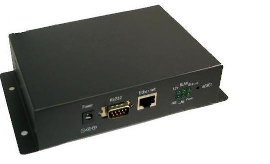
17 3 Hardware Reference This section gives an overview of the hardware features of the Streamer VIP. The overview includes location and function of connectors, indicators, and switches. 3.1 Connectors The following diagram illustrates the location of connectors on the Streamer VIP. Power RS232 Ethernet USB RS485 Rly1-2 IN1-4 Video Out Video In Wireless Antenna (optional) Audio In , preliminary Page 11
18 The following table provides details about connector type and functionality. Connector Enclosure Connector Mating Connector Description Power DC socket 2 mm DC plug 2 mm 12 VDC power input RS232 DB-9 socket DB-9 plug Serial interface Ethernet RJ-45 jack RJ-45 plug 10/100 Mbps Ethernet network USB RS485 Rly1-2 IN1-4 USB Type A receptacle Header 2 pin, P/N Header 10 pin, P/N USB Type A plug USB 1.1 Host port Serial interface Two relay outputs (Section 4.5) Four TTL general purpose inputs (Section 4.5) Video Out BNC socket BNC plug Straight through output from Video In 2 Video In BNC socket BNC plug Analog video input Audio In BNC socket BNC plug Analog audio input Wireless Antenna (optional) Wireless network adapter 2 Video In is connected directly to Video Out bypassing the ARM9 core and MPEG4 encoder. You can connect Video Out to a TV monitor to display the video before encoding. Page , preliminary
19 Hardware Reference 3.2 Indicators and Switches The Streamer VIP has six onboard light-emitting diodes (LEDs) indicating system operation, in addition to a reset switch. The following diagram illustrates the location of the LEDs and reset switch, while the table describes LED functionality. LED 12V WLAN Status POE LAN Power Description On indicates a 12 VDC power adapter powers the Streamer VIP. Blinking indicates activity over a wireless network. Blinking indicates the Streamer VIP is booting. On indicates the Streamer VIP is operating. Off indicates a failure during boot. On indicates the Ethernet cable powers the Streamer VIP. Blinking indicates Ethernet activity. On indicates the power subsystem is operating. The reset switch is located on the front panel of the enclosure. Pressing this switch for more than 5 seconds restores the factory-default system settings. This system reset requires several seconds , preliminary Page 13
20 (This page intentionally blank) Page , preliminary

21 4 System Configuration The Streamer VIP provides a flexible solution for a variety of VIP applications. You can easily configure the Streamer VIP to meet your application requirements and your existing network structure. The web server enables you to customize the Streamer VIP for your needs. This section provides details on each Streamer VIP web page. 4.1 Account The Account page allows you to manage user accounts and to include a time stamp with the video. The next screen capture illustrates the Account page Account Management In addition to the default administrative account, you can add up to ten accounts, edit existing accounts, and delete accounts in the Account web page. Manage User Accounts To add, delete or edit an account, complete the following steps in the Account page: 1. To add an account, complete the following steps: a. Click the Add button in the Account List area. The Add User dialog box appears. b. Choose Guest or Administrator in the User Group list. c. Type a new user name and new password. d. Confirm the new password. e. Click the Add button. The new account is added, and the user name is displayed in the Account List area , preliminary Page 15
22 2. To delete an account, complete the following steps: a. Select the unwanted account in the Account List area. b. Click the Delete button. c. Confirm the delete. The account is deleted, and the user new is removed from the Account List area. 3. To edit an account, complete the following steps: a. Select the account in the Account List area. b. Click the Edit button. The Edit User dialog box appears. c. Type the original password, new user name, and new password. d. Confirm the new password. e. Click the Apply button. The account is changed, and the new information is displayed in the Account List area Video Server Time Stamp Configure Video Server Time Stamp To configure the Video Server Time stamp, complete the following steps in the Account page: 1. To change the Streamer VIP name, type a new name into the Video Server Name box. Only the first twenty characters of the Video Server Name are displayed. 2. To set the Video Server Time, select one of the following methods: a. To synchronize with your computer time, select the Syns with Computer time check box. b. To set the date and time manually, select the Manual Set Up check box. Choose the date and time. c. To set the date and time automatically, select the Network Time Protocol check box. Choose the NTP Server and Time Zone. Type a value into the Update Interval box. 3. To add a time stamp to the display, choose Top or Bottom from the Display Position list. The time stamp features allows you to include the Video Server Name, System Time and Session Number in the video displayed by the web server. The time stamp appears on the top or bottom of the display. 4. Click the Apply button. The Streamer VIP saves the new logo and reboots to validate the change. Page , preliminary
23 System Configuration Logo The Streamer VIP is shipped without a logo on the web pages. You can add your company s logo using the web server. Add Logo To add a logo, complete the following steps in the Account page: 1. Click the Browse button on the right side of the Logo box. You can browse your disk drive for the logo file. 2. Select the logo file, and then click Open. The highlighted file appears in the Logo box. 3. Click the Apply button. The Streamer VIP saves the new logo and reboots to validate the change. 4. Close the web browser. 5. Log in to the web server again. The new logo appears on the web page , preliminary Page 17

24 4.2 System The System page allows you to configure the service ports, multicast communication, SMTP setting and FTP setting, in addition to restoring the factory settings and to updating the firmware. The next screen capture illustrates the System page Service Ports If there are multiple Streamer VIPs connected to the same local area network (LAN), you must assign each Streamer VIP a different IP address; however, the service ports of each Streamer VIP can be the same. Notice that the Streamer VIP includes three different service ports. Configure Service Ports To configure the service ports, complete the following steps in the System page: 1. Type values into the Http Port, Stream Port, and Stream Control Port boxes for each Streamer VIP in the Service area. The following are the default values for the service ports: Http Port 80 Stream Port 5119 Stream Control Port Click the Apply button. The Streamer VIP saves all settings and reboots to validate the change. Page , preliminary
25 System Configuration If there are multiple Streamer VIPs connected to the Internet through a router or firewall, you must assign different values for the service ports of each Streamer VIP, and you must configure the network address translation (NAT) table for the firewall or router. Configure Firewall or Router To configure the NAT of the firewall or router, complete the following steps: 1. Log in to the firewall. 2. Configure static NAT. The following table is an example configuration for three Streamer VIPs connected to the Internet through a firewall at IP address Notice that each Streamer VIP is assigned a different IP address and that the three service ports of each Streamer VIP are assigned different values. These values correspond to the external IP address port values. External IP Address IP: Port: 81 IP: Port: 82 IP: Port: 83 IP: Port: 5118 IP: Port: 5119 IP: Port: 5120 IP: Port: 5121 IP: Port: 5122 IP: Port: 5123 Streamer VIP Configuration IP: Port: 81 IP: Port: 82 IP: Port: 83 IP: Port: 5118 IP: Port: 5119 IP: Port: 5120 IP: Port: 5121 IP: Port: 5122 IP: Port: 5123 Function Streamer VIP 1, Http Port Streamer VIP 2, Http Port Streamer VIP 3, Http Port Streamer VIP 1, Stream Port Streamer VIP 1, Stream Control Port Streamer VIP 2, Stream Port Streamer VIP 2, Stream Control Port Streamer VIP 3, Stream Port Streamer VIP 3, Stream Control Port After you have configured the service ports for the Streamer VIPs and NAT for the firewall or router, you can log in to the web server of each Streamer VIP. For example, you access the Streamer VIP 1 Http Port configured as , Port 81 at IP address Multicast Configuration IP multicast is an efficient method to send information from one sender to multiple receivers simultaneously. The receivers join a multicast group designated by a multicast group address. The sender sends its data packets to the multicast group address without knowledge of the individual receivers. All receivers that have joined the group receive the data packets. In a multicast configuration, one Streamer VIP streams video to many receivers. By default, multicast is disabled. You configure the Streamer VIP for multicast using the System page , preliminary Page 19
26 Configure Multicast Settings To enable multicast communication, complete the following steps in the System page: 1. Select the Multicast Switch On check box in the Multicast area. 2. Type values into the Multicast Address and Multicast Port boxes. 3. Click the Apply button. The Streamer VIP saves all settings and reboots to validate the change. After reboot, the Streamer VIP will send video and audio to the assigned multicast group SMTP and FTP Settings The Streamer VIP has the capability to images to a specific account and FTP images to a remote site when a pre-defined event occurs. See Section 4.5 for a complete explanation of the events. Configure SMTP Settings To images to a specific account, complete the following steps in the System page: 1. Type values into the SMTP Server, SMTP Account, SMTP Password, Recipient Mail Address, and Send Mail Address boxes in the SMTP area. 2. Click the Apply button. The Streamer VIP saves all settings and reboots to validate the change. Configure FTP Settings To FTP images to a remote site, complete the following steps in the System page: 1. Type values into the FTP Server Port, FTP Site, Account, Password, and Path boxes in the FTP area. 2. Click the Apply button. The Streamer VIP saves all settings and reboots to validate the change Upgrade Firmware You can upgrade the firmware using the web server. Notice that the System page contains the current firmware version number. Upgrade Firmware To upgrade to a new version of firmware, complete the following steps in the System page: 1. Click the Browse button on the right side of the Image File box. You can browse your disk drive for the firmware file. 2. Select the firmware file, and then click Open. The highlighted file appears in the Image File box. 3. Click the Update button following the Image File box. The Streamer VIP saves all settings and reboots to validate the change. Do not interrupt the update process or disrupt the power to the Streamer VIP until the update is complete. 4. Close the web browser. 5. Log in to the web server again. The new firmware version number appears in the Update Firmware area. Page , preliminary

27 System Configuration Restore Factory Setting The Streamer VIP is shipped with factory-default settings as given in each section of this manual. In addition to pressing the reset switch as described in Section 3.2, you can restore the factorydefault settings using the System page. To restore the factory-default system settings, click the Restore button. The Streamer VIP restores all factory-default settings and reboots to validate the change. 4.3 Network The Streamer VIP is easily customized to operate in any network. It supports operation in a LAN or over the Internet. You configure network settings in the Network web page. The following screen capture illustrates the Streamer VIP Network Page , preliminary Page 21


28 4.3.1 Local Area Network (LAN) In a LAN, one of two methods sets the IP address of the Streamer VIP: static local IP and dynamic local IP. In a static local IP configuration, your administrator assigns one local IP address for the Streamer VIP. The following diagram illustrates the network topology for static local IP mode. In a dynamic IP configuration, the DHCP server in the same LAN assigns the IP address to the Streamer VIP. The following diagram illustrates the network topology for dynamic local IP mode. Player VIP Camera TV, LCD TV or VGA monitor Streamer VIP DHCP Server Network Hub or Switch Page , preliminary
29 System Configuration Configure LA etwork Settings To connect the Streamer VIP to a LAN, complete the following steps in the Network page: 1. Do not select the Enable Internet Access check box in the Internet Access area. 2. Select the Wire or Wireless check box in the Network Interface area. Wire allows you to use the 10/100 Mbps Ethernet connection to a network. If your Streamer VIP includes the wireless option, select Wireless to connect to an g/b wireless network. 3. Select the Static IP or DHCP check box in the Net Type area. Static IP allows you to assign a static IP address, while DHCP allows your server to assign a dynamic IP address. a. If you selected Static IP and Wire, type values into the IP Address, Subnet Mask, and Default Gateway boxes in the Wire Network area. The following are the default values for the Wire Network Static IP boxes: IP Address Subnet Mask Default Gateway b. If you selected Static IP and Wireless, type values into the Mode, ESSID, IP Address, Subnet Mask, and Default Gateway boxes in the Wireless LAN area. The following are the default values for the Wireless LAN Static IP boxes: 4. Click the Save button. Mode AP ESSID G2000 IP Address Subnet Mask Default Gateway The Streamer VIP saves all settings and reboots to validate the change , preliminary Page 23
30 4.3.2 Internet When you access the Streamer VIP over the Internet, one of four methods sets the Streamer VIP IP address: Public IP, ADSL, Private IP, or Relay. You configure each method using the Network web page. When assigned as a public IP, the Streamer VIP IP address is global and static. The following diagram illustrates the network topology for Public IP mode. In the ADSL configuration, the Streamer VIP connects to the Internet using an ADSL modem. The following diagram illustrates the network topology for ADSL mode. If your network accesses the Internet through a firewall or router, you can assign the Streamer VIP a private IP address. In this configuration, the IP address is not global. The following diagram illustrates the network topology for Private IP mode. Page , preliminary
31 System Configuration The Streamer VIP also supports networks that access the Internet through a relay server. In Relay mode, the Streamer VIP IP address is not global. The relay server must have one public IP address, and the relay server software must be installed. See Section for information about the relay server software. The following diagram illustrates the network topology for Relay mode. Configure Internet etwork Settings To connect the Streamer VIP to the Internet, complete the following steps in the Network page: 1. Select the Enable Internet Access check box in the Internet Access area. 2. Select the Wire or Wireless check box in the Network Interface area. Wire allows you to use the 10/100 Mbps Ethernet connection to a network. If your Streamer VIP includes the wireless option, select Wireless to connect to an g/b wireless network. 3. Select the Static IP, DHCP, or PPPoE check box in the Net Type area. Static IP allows you to assign a static IP address, while DHCP allows your server to assign a dynamic IP address. PPPoE enables the Streamer VIP to access the Internet through an ADSL modem. a. If you selected Static IP and Wire, type values into the IP Address, Subnet Mask, and Default Gateway boxes in the Wire Network area. The following are the default values for the Wire Network Static IP boxes: IP Address Subnet Mask Default Gateway , preliminary Page 25
32 b. If you selected Static IP and Wireless, type values into the Mode, ESSID, IP Address, Subnet Mask, and Default Gateway boxes in the Wireless LAN area. The following are the default values for the Wireless LAN Static IP boxes: Mode AP ESSID G2000 IP Address Subnet Mask Default Gateway c. If you selected PPPoE, type values into the User Name and Password boxes in the PPPoE area. Use the User Name and Password that your ISP assigned to your ADSL. 4. Select the Obtain DNS Automatically or Use Following DNS check box in the DNS area. a. If you selected Obtain DNS Automatically, type values into the Provider, User Name, Password, and Domain Name boxes in the Dynamic DNS area. Your ISP assigns the Primary DNS and Secondly DNS. The Streamer VIP supports service client. You may register at for a User Name, Password, and Domain Name. b. If you selected Use Following DNS, type values into the Primary DNS and Second DNS boxes in the DNS area. 5. Click the Save button. The Streamer VIP saves all settings and reboots to validate the change. Page , preliminary
 and PAL (720 x 576).")
33 System Configuration 4.4 Multimedia Multimedia settings can be adjusted to optimize application performance. The Multimedia page enables you to configure the video and audio of the Streamer VIP. The next screen capture illustrates the Multimedia page Video The Streamer VIP supports NTSC or PAL composite video inputs at resolutions up to NTSC (720 x 480) and PAL (720 x 576). You can configure the display orientation, image setting, performance, GOP Size, and compression in the Multimedia page. Configure Video To configure the Streamer VIP video, complete the following steps in the Multimedia page: 1. Select the Flip or Mirror check box in the Display Orientation area, if required by your application. Display Orientation allows you to change the appearance of the video displayed. You can flip and mirror the display. 2. Adjust the video output in the Image Setting area. a. Set the Brightness, Contrast, Saturation, and Hue. The following are the default values: Brightness 50 Contrast 50 Saturation 50 Hue 0 b. Click the Apply button , preliminary Page 27
34 3. Select the Quality or Bandwidth check box in the Performance area. You can optimize the performance for quality or bandwidth. 4. Select the Full-D1, VGA, QVGA, or QQVGA check box in the Resolution area. 5. Adjust the Frame Rate. The Streamer VIP supports frame rates up to 30 fps for NTSC and 25 fps for PAL. 6. Adjust the Bit Rate. The Streamer VIP supports bit rates from 32 kbps to 4 Mbps. 7. Select the 15, 30, 60, or 90 check box in the GOP Size area. GOP Size allows you to select the group of pictures (GOP) size. 8. Select the MPEG-2 or MPEG-4 check box in the Stream Mode area. The Streamer VIP supports MPEG-2 and MPEG-4 image compression. 9. Click the Apply button. The Streamer VIP saves all settings and reboots to validate the change. Notice that the Channel box is not used Audio The Streamer VIP accepts a mono audio input. You can disable the audio and adjust the audio sample rate using the Multimedia page. Configure Audio To configure the Streamer VIP audio, complete the following steps in the Multimedia page: 1. If your application does not require audio, select the Disable check box in the Audio Sample Rate area. Disable the audio if your network bandwidth is low. 2. If your application requires audio, select the 8K or 48K check box in the Audio Sample Rate area. 3. Click the Apply button. The Streamer VIP saves all settings and reboots to validate the change. Page , preliminary
 and motion detection. Motion detection and GPI triggering can be used simultaneously.")
35 System Configuration 4.5 Event Applications such as security monitoring often require programmable events based upon external triggers. The Event web page enables you to trigger events on a general-purpose input (GPI) and motion detection. Motion detection and GPI triggering can be used simultaneously. When a trigger occurs, the Streamer VIP can perform one of the following actions: Store images to an internal buffer Send FTP images to a remote site images to a specific account Control external devices using two relay outputs The next screen capture illustrates the Event page. Notice that GPI1-GPI4 correspond to the inputs of the rear panel connector labeled IN1-IN4, and that GPO1 and GPO2 correspond to the outputs of the rear panel connector labeled Rly1-Rly Motion Detection Trigger The Streamer VIP monitors up to three regions for motion. Configure Motion Detection Trigger To set a motion detection trigger, complete the following steps in the Event page: 1. Select up to three region check boxes in the Motion Detection area located near the top of the window. A box appears on the display for each region that is enabled. 2. Drag the pointer to re-size and re-position the motion detection regions in the display area. 3. Select the check boxes for the events to trigger in the Motion Detection area located near the bottom of the window. You can select up to four events to occur: GPO1 (Rly 1), GPO2 (Rly 2), Mail or FTP. See Section for configuration of and FTP , preliminary Page 29
36 4. If you selected a GPO trigger check box, select the Continue check box and type a value into the Seconds box in the GPO Duty Cycle area. The value in the Seconds box is the duration of the GPO signal when triggered. 5. If you selected the Mail or FTP check box, complete the following steps: a. Type a value into the Seconds Cycle to Trigger Mail and FTP box in the Alarm Trigger Cycle area. The value in the Seconds Cycle to Trigger Mail and FTP box is the interval between alarm triggers. The mail and FTP alarm action will trigger once during this interval regardless of how many alarm trigger events occur. This feature reduces the number of redundant alarm actions. b. Choose the number of frames to record before and after the event trigger in the Event Recording area. You can independently choose 30, 60, or 90 frames before and after the trigger. 6. Click the Apply button. The Streamer VIP saves all settings and reboots to validate the change General Purpose Input Trigger The Streamer VIP includes four GPIs that trigger events. Configure External Input Trigger To set a GPI trigger, complete the following steps in the Event page: 1. To configure each external input, complete the following steps in the GPIO Port area: a. Choose High Level or Low Level for each GPI trigger. You can assign a name to the GPI by typing the name into the box to the right of each GPI. Notice that the maximum length of the name is 31 characters. b. Select the check boxes for the events to trigger. You can select up to four events to occur: GPO1 (Rly 1), GPO2 (Rly 2), Mail or FTP. See Section for configuration of and FTP. 2. If you selected a GPO trigger check box, select the Continue check box and type a value into the Seconds box in the GPO Duty Cycle area. The value in the Seconds box is the duration of the GPO signal when triggered. 3. If you selected the Mail or FTP check box, complete the following steps: a. Type a value into the Seconds Cycle to Trigger Mail and FTP box in the Alarm Trigger Cycle area. The value in the Seconds Cycle to Trigger Mail and FTP box is the interval between alarm triggers. The mail and FTP alarm action will trigger once during this interval regardless of how many alarm trigger events occur. This feature reduces the number of redundant alarm actions. b. Choose the number of frames to record before and after the event triggers in the Event Recording area. You can independently choose 30, 60, or 90 frames before and after the trigger. 4. Click the Apply button. The Streamer VIP saves all settings and reboots to validate the change. Page , preliminary
 protocol defines camera control.")
37 System Configuration 4.6 Camera Control The Streamer VIP provides the capability to control a camera remotely. The EIA-485 serial port located on the rear panel connects to the camera. You can control various functions using the Streamer VIP web page shown in the next screen capture. A Pan, Tilt, Zoom (PTZ) protocol defines camera control. Different camera manufacturers use different protocols, and there is no international standard protocol for all cameras. The Streamer VIP supports the PELCO-P/PELCO-D protocol defined by Pelco Inc , preliminary Page 31
38 (This page intentionally blank) Page , preliminary
39 5 Troubleshooting Guide The following are some of the most common problems that occur during installation or operation: Q: Why am I unable to connect to the Streamer VIP over the LA? A: Do the following to resolve this problem: Check the power to the Streamer VIP. Verify the IP address of the Streamer VIP. PING the Streamer VIP to verify operation of the network. Q: What can I do if I forget the IP address of the Streamer VIP? A: Press the reset button for five or more seconds. The Streamer VIP will reset the IP address to and the subnet mask to Q: Why is there no video output from the Streamer VIP, even though I can log in to the Streamer VIP web server with Internet Explorer? A: One of the following reasons causes this problem: If the screen shows the message Video Lost, the Streamer VIP is not receiving a video input. The security setting of Internet Explorer forbids the ActiveX plug-in from downloading or running. Add a link for the Streamer VIP as a trusted site. A third-party software application installed on your laptop forbids the ActiveX plug-in from downloading or running. Temporarily disable the security feature of the application. Q: Why does the video not play smoothly? A: One of the following reasons causes this problem: The frame rate of the Streamer VIP is too low. Increase the frame rate. There are too many clients connected to the same Streamer VIP. Do one of the following: Close the unused clients. Set the Streamer VIP frame rate or bit rate lower. The bandwidth of the network is too low, and many frames have been dropped. Decrease the frame rate or bit rate of the video to economize bandwidth. Your laptop is not capable of playing high performance media. Q: Why does the video play without audio? A: One of the following reasons causes this problem: The audio input is not connected. The audio of the Streamer VIP is disabled. To enable the audio, configure the audio sample rate to 48K or 8K , preliminary Page 33
40 Q: Why does the audio not play smoothly? A: One of the following reasons causes this problem: The bandwidth of the network is too low. Your laptop is not capable of playing high performance media. Your audio adapter driver is not functioning. Q: Why am I unable to play the video and audio that I recorded as AVI files using the web server? A: You may not have the latest Xvid plug-in. Download the latest version at Q: Why does the Logo not change after I update it? A: After you update the Logo, you must log in to the web server twice before the Logo changes. Q: Why does the time reset to the original time after I set a new time successfully? A: The battery is not installed on the Streamer VIP printed circuit board. Page , preliminary
41 6 System Specifications This section provides the system specifications for the Streamer VIP. 6.1 Mechanical Specifications The Streamer VIP is a fully enclosed system. Dimensions of the enclosure are 180mm x 110mm x 41mm. (7.1 inch x 4.3 inch x 1.6 inch). 6.2 Environmental Specifications The following are environmental specifications for the Streamer VIP. Parameter Min Typ. Max Units Operating temperature C Humidity % 6.3 Power Specifications The following are power specifications for the Streamer VIP. Symbol Parameter Min Typ. Max Units System Power Vin Supply voltage V Pin Power consumption 4.8 W 6.4 Audio Specifications The following are specifications for the Streamer VIP audio input. Symbol Parameter Min Typ. Max Units Audio Vin Input voltage 2.0 V RMS Rin Input resistance 4.7 kω 6.5 Electrical Specifications The following are electrical specifications for the Streamer VIP general-purpose inputs, IN1-IN4, and relay outputs, Rly1-Rly2. Symbol Parameter Min Typ. Max Units IN1-IN4 (GPI) Vin Input voltage V Rly1-Rly2 (GPO) Contact 120 VAC 3 A Control voltage 24 VDC , preliminary Page 35
42 (This page intentionally blank) Page , preliminary
43 7 Product Revision History This section provides the product revision history for the Streamer VIP. 7.1 Hardware Revision This section lists the item numbers and revision history for the Streamer VIP Identifying the Product The item number of the Streamer VIP is NVIP2010. The item number of the wireless Streamer VIP is NVIP Revision History The following is an overview of the revisions of the Streamer VIP. Revision V2.3 Initial release 7.2 Firmware Revision This section describes the Streamer VIP firmware revisions Identifying the Revision The Streamer VIP firmware version number is given in the System web page Revision History The following is an overview of the Streamer VIP firmware revisions. Version Initial release , preliminary Page 37
VideoCenter User s Manual
 VideoCenter User s Manual About this Manual This manual documents the VideoCenter revision V1.0.8. For a complete revision history, see the Eurotech support forum. Organization of this Manual The manual
C1002 IP Camera. Quick Installation Guide. Solwise Ltd., 1
 C1002 IP Camera Quick Installation Guide Solwise Ltd., www.solwise.co.uk, sales@solwise.co.uk 1 Trademarks and/or registered trademarks are the property of their respective owners The information presented
IP SERVER 9310 User Manual
 IP SERVER 9310 User Manual USER MANUAL IP Server 9310 Version: 1.0 2007.3-1 - Warning: any changes to this equipment without permission may cause damages to your equipment! This equipment has been proved
Video Server D1. User s Manual
 Video Server D1 User s Manual i Video Server D1 10 th Oct, 2004 Table of Contents H1 INTRODUCTION 1-1 1.1 PACKAGE CONTENTS...1-1 1.2 FEATURES AND BENEFITS...1-2 1.3 PHYSICAL DESCRIPTION...1-4 1.3.1 RS-485
IP-001T Video Server Products Series. User Manual & Installation Guide
 Page 1 of 29 IP-001T Video Server Products Series User Manual & Installation Guide Version: 1.0 Page 2 of 29 Table of Contents TABLE OF CONTENTS...2 WHAT IS VIDEO SERVER?...3 PRODUCT FEATURES...3 2. PHYSICAL
Lite H.264 DVR Setup Guide
 Package Content Lite H.264 DVR Setup Guide Inspect the packaging carton. Make sure the Lite H.264 DVR is properly delivered. Remove all items from the box and make sure the box contains the following items.
Veo Europe VSD-2000_PT_IR Observer IP Speed Dome Pan/Tilt with Infra/Red Products Series. User Manual & Installation Guide
 Page 1 of 32 Veo Europe VSD-2000_PT_IR Observer IP Speed Dome Pan/Tilt with Infra/Red Products Series User Manual & Installation Guide Version: 1.0 Date: August 24, 2005 Page 2 of 32 Table of Contents
GRAND IP VIDEO SERVER PRO. User s Manual INDEX
 INDEX GRAND IP VIDEO SERVER PRO Video & Audio Transmission/ iphone Web Browser Support User s Manual ISSUE:Mar 16, 2010 1. Package Contents.... 1 2. Introduction.... 1 3. System Requirements...... 1 4.
960H H.264 DVR Setup Guide
 Package Content 960H H.264 DVR Setup Guide Inspect the packaging carton. Make sure the 960H H.264 DVR is properly delivered. Remove all items from the box and make sure the box contains the following items.
Features and Benefits. Certifications
 VPort 464 Series Superior video performance, 4-channel industrial video encoders Features and Benefits Each channel supports 2 D1 30 fps streams simultaneously, or merge 1 quad stream 30 fps image into
TCD channel H.264 Video Encoder Hardware User s Manual (DC 12V) Ver. 2010/10/29
 Ver. 2010/10/29") TCD-2100 1-channel H.264 Video Encoder Hardware User s Manual (DC 12V) Ver. 2010/10/29 Table of Contents 0. Precautions 3 1. Introduction 4 Package Contents... 4 Features and Benefits... 5 Safety Instructions...
TCD-2100 1-channel H.264 Video Encoder Hardware User s Manual (DC 12V) Ver. 2010/10/29 Table of Contents 0. Precautions 3 1. Introduction 4 Package Contents... 4 Features and Benefits... 5 Safety Instructions...
VIDEO WEB SERVER. User s Manual. Please read instructions thoroughly before operation and retain it for future reference. PATENT 732 V1.
 VIDEO WEB SERVER PATENT User s Manual Please read instructions thoroughly before operation and retain it for future reference. 732 V1.0 WARNING The apparatus shall not be exposed to dripping or splashing
User s Manual November 2004 V 1.1
 User s Manual Please read instructions thoroughly before operation and retain it for future reference. November 2004 V 1.1 WS2 WARNING The apparatus shall not be exposed to dripping or splashing and that
TCD channel H.264 Video Encoder with WDR (DC 12V) Ver. 2012/6/25
 Ver. 2012/6/25") TCD-2500 1-channel H.264 Video Encoder with WDR (DC 12V) Ver. 2012/6/25 Table of Contents 0. Precautions 3 1. Introduction 4 Package Contents... 4 Features and Benefits... 5 Safety Instructions... 7 Physical
TCD-2500 1-channel H.264 Video Encoder with WDR (DC 12V) Ver. 2012/6/25 Table of Contents 0. Precautions 3 1. Introduction 4 Package Contents... 4 Features and Benefits... 5 Safety Instructions... 7 Physical
Cisco WVC210 Wireless-G Pan Tilt Zoom (PTZ) Internet Video Camera: 2-Way Audio Cisco Small Business Video Surveillance Cameras
 Internet Video Camera: 2-Way Audio Cisco Small Business Video Surveillance Cameras") Cisco WVC210 Wireless-G Pan Tilt Zoom (PTZ) Internet Video Camera: 2-Way Audio Cisco Small Business Video Surveillance Cameras High-Quality, Flexible, Remote-Controlled Wireless Video Solution for Your
Cisco WVC210 Wireless-G Pan Tilt Zoom (PTZ) Internet Video Camera: 2-Way Audio Cisco Small Business Video Surveillance Cameras High-Quality, Flexible, Remote-Controlled Wireless Video Solution for Your
IPC Online Operation Manual
 IPC Online Operation Manual 1 Overview An IP camera (hereinafter referred to as IPC) is a new product integrating network video technologies into a traditional camera. The IPC can realize simpler monitoring
H.264 Internet Video Server
 H.264 Video Server Key Features Video / Audio H.264 / MPEG-4 and M-JPEG video compression simultaneously Simultaneous multi-stream support Up to 30/25 (NTSC/PAL) fps for all profiles 3DNR (3D Noise Reduction)
F Series Indoor Fixed IP Camera. Quick Start Guide
 F Series Indoor Fixed IP Camera Quick Start Guide Welcome Thank you for purchasing our IP camera! Before install and use the IP camera, please read the following section carefully. Please keep this start
GV-IP Decoder Box Plus User s Manual
 GV-IP Decoder Box Plus User s Manual Before attempting to connect or operate this product, please read these instructions carefully and save this manual for future use. DBPV10-UM-A 2015 GeoVision, Inc.
IP WEB User Manual V2.0
 IP WEB User Manual V2.0 Please read carefully before installing or contacting your supplier. The information contained at the time of printing is correct, but is subject to change without notice. This
R4, R8, R16 Digital Video Recorders Quick Setup Guide
 R4, R8, R16 Digital Video Recorders Quick Setup Guide This guide provides instructions to initially setup the R16 (16 channel) digital video recorders (DVR). The DVR supports these advanced features: 2
Cisco WVC210 Wireless-G Pan Tilt Zoom (PTZ) Internet Video Camera: 2-Way Audio Cisco Small Business Video Surveillance Cameras
 Internet Video Camera: 2-Way Audio Cisco Small Business Video Surveillance Cameras") Cisco WVC210 Wireless-G Pan Tilt Zoom (PTZ) Internet Video Camera: 2-Way Audio Cisco Small Business Video Surveillance Cameras High-Quality, Flexible, Remote-Controlled Wireless Video Solution for Your
Cisco WVC210 Wireless-G Pan Tilt Zoom (PTZ) Internet Video Camera: 2-Way Audio Cisco Small Business Video Surveillance Cameras High-Quality, Flexible, Remote-Controlled Wireless Video Solution for Your
BIPAC-6500 / 6500W (Wireless) Broadband VPN Firewall Router with 4-port 10/100M Switch Quick Start Guide
 Broadband VPN Firewall Router with 4-port 10/100M Switch Quick Start Guide") BIPAC-6500 / 6500W (Wireless) Broadband VPN Firewall Router with 4-port 10/100M Switch Quick Start Guide Billion BIPAC-6500 / 6500W (Wireless) Broadband VPN Firewall Router For more detailed instructions
BIPAC-6500 / 6500W (Wireless) Broadband VPN Firewall Router with 4-port 10/100M Switch Quick Start Guide Billion BIPAC-6500 / 6500W (Wireless) Broadband VPN Firewall Router For more detailed instructions
Wireless PTZ Cloud Camera TV-IP851WC (v1.0r)
") (v1.0r) TRENDnet s Wireless PTZ Cloud Camera, model, takes the work out of viewing video over the internet. Previously to view video remotely, users needed to perform many complicated and time consuming
(v1.0r) TRENDnet s Wireless PTZ Cloud Camera, model, takes the work out of viewing video over the internet. Previously to view video remotely, users needed to perform many complicated and time consuming
F Series Robot Model IP Camera V2.3 User Manual
 F Series Robot Model IP Camera 2010-5 V2.3 User Manual Index 1 INTRODUCTION... 4 2 FUNCTION AND FEATURES... 4 3 APPEARANCE AND INTERFACE... 5 3.1 APPEARANCE... 5 3.2 INTERFACE OF EQUIPMENT... 6 4 NETWORK
VK2-ENCODER. Installation Guide
 VK2-ENCODER Installation Guide This page is intentionally left blank 1. Product Description This manual applies to the VIP Kit2 Camera VK2-ENCODER The VK2-ENCODER supports the network service for an existing
Network / IP Camera User Manual
 Network / IP Camera User Manual Preface Congratulations on your purchase of this product. Read this manual carefully and keep it in a safe place for future reference. About this manual This user manual
Specifications of Mobile DVR VP 5004
 Specifications of Mobile DVR VP 5004 Model Name Video Input VP-5004 Video BNC input x 4 *CHANGEABLE / CUSTOMIZED AVAILABLE* Note: VP-5004 also supports IP Camera over Cat5 cable. Please contact our sales
Standard H.264 DVR Setup Guide
 Package Content Standard H.264 DVR Setup Guide Inspect the packaging carton. Make sure the Standard H.264 DVR is properly delivered. Remove all items from the box and make sure the box contains the following
Wireless Pan & Tilt Camera
 User Manual Wireless Pan & Tilt Camera CIPCAMPTIWL v1.0 Index 1 INTRODUCTION... 4 1.1 THE PACKAGE INCLUDES... 4 1.2 FUNCTION AND FEATURES... 4 1.3 TECHNICAL SPECIFICATIONS... 4 2 APPEARANCE AND INTERFACE...
Installation Instructions Fig. 3 Side View. No. Label Operation
 One-Camera IP Video Server In G Out G D+ D- Installation Instructions 1507280 Part Number: CM2002 - One-Camera IP Video Server CM2002 IP Video Server Features In G Out G D+ D- DO G DI G Out In Video In
F312A IP Camera. Firmware User Manual
 0 F312A User Manual F312A IP Camera F312A User Manual Firmware User Manual - Contents - CHAPTER 1. MINIMUM SYSTEM REQUIREMENT...2 CHAPTER 2. USING IP CAMERA VIA WEB BROWSER...3 2.1WINDOWS WEB BROWSER...3
AVE DR16X / AVE DR8X Quick Installation Guide
 AVE DR16X / AVE DR8X Quick Installation Guide Package Content Inspect the packaging carton. Make sure your AVE DR16X / AVE DR8X is properly delivered. Remove all items from the box and make sure the box
Configuring and Managing the IP Camera
 CHAPTER 3 The Cisco Video Surveillance IP Camera provides configuration windows that you use to configure and manage the IP camera. This chapter explains how to access the configuration windows, describes
 DESCRIPTION ------------------------------------------------------------------------------------------------------------------------------------- The HEB Series camera is an internet protocol based megapixel
1. PRODUCT FEATURES INSTALLATION...
 0 Contents 1. PRODUCT FEATURES... 2 2. INSTALLATION... 3 2.1 INSTALL CAMERA... 3 2.2 ASSIGN IP ADDRESS... 4 2.3 ACCESS FROM A BROWSER... 4 2.4 ACCESSING THE CAMERA FROM THE INTERNET... 5 2.5 ADJUSTING
GV-Video Server. User's Manual
 GV-Video Server User's Manual Before attempting to connect or operate this product, please read these instructions carefully and save this manual for future use. 2009 GeoVision, Inc. All rights reserved.
DVR RANGE ENGINEER MANUAL
 INSPIRE DVR RANGE ENGINEER MANUAL Contents Hardware Inspire DVR range Connections Connecting a mouse Connecting keyboard Connecting PTZ cameras Connecting Keyboard/PTZ Alarm connections Using front panel
Video Web Server. User s s Manual MPEG-4 VIDEO WEB SERVER. Please read instructions thoroughly before operation and retain it for future reference.
 13 Video Web Server MPEG-4 VIDEO WEB SERVER User s s Manual Please read instructions thoroughly before operation and retain it for future reference. 733_V0.95 Thank-You Note Before You Get Start First
F510E BOX IP Camera. Firmware User Manual
 0 F510E User Manual F510E BOX IP Camera F510E User Manual Firmware User Manual - Contents - CHAPTER 1. MINIMUM SYSTEM REQUIREMENT... 2 CHAPTER 2. USING IP CAMERA VIA WEB BROWSER... 3 CHAPTER 3. USING IP
NUBIX H.264 DVR Setup Guide
 Package Content NUBIX H.264 DVR Setup Guide Inspect the packaging carton. Make sure the NUBIX H.264 DVR is properly delivered. Remove all items from the box and make sure the box contains the following
Wireless Day / Night Cloud Camera TV-IP751WIC (v1.0r)
") (v1.0r) TRENDnet s Wireless Day / Night Cloud Camera, model, takes the work out of viewing video over the internet. Previously to view video remotely, users needed to perform many complicated and time
(v1.0r) TRENDnet s Wireless Day / Night Cloud Camera, model, takes the work out of viewing video over the internet. Previously to view video remotely, users needed to perform many complicated and time
Introduction. IP Camera (including Storage IP Camera, WiFi/Storage IP Camera, IR Dome IP Camera, IR
 MANUAL Introduction Thank you for purchasing IP Cameras. A IP Camera (including Storage IP Camera, WiFi/Storage IP Camera, IR Dome IP Camera, IR Day and Night Waterproof IP Camera, and High Speed Dome
Wireless LAN Access Point
 Wireless LAN Access Point IEEE 802.11b 11Mbps User s Manual Table of Contents Chapter 1 Introduction... 1 1.1 Package Contents... 2 1.2 Features... 2 1.3 Specifications... 2 1.4 Physical Description...
Quick Installation Guide of Acer WLAN 11b Broadband Router
 Preparation 1 At lease one PC with IEEE802.11b WLAN client installed. 2 One straight-through Category 5 Ethernet cable, used to link WAN interface to xdsl or CM for Internet connection. 3 Acer WLAN 11b
NFD30 Network Dome Camera MPEG4 + Motion-JPEG Dual Mode, PoE, Audio, 300k CMOS, mm vari-focal lens Part No.:
 NFD30 Network Dome Camera MPEG4 + Motion-JPEG Dual Mode, PoE, Audio, 300k CMOS, 3.7 12 mm vari-focal lens Part No.: 550987 The INTELLINET NETWORK SOLUTIONS NFD30 Network Dome Camera is designed for security
Configuring and Managing the IP Camera
 CHAPTER 3 The Cisco Video Surveillance IP Camera provides configuration windows that you use to configure and manage the IP camera. This chapter explains how to access the configuration windows, describes
H.264 PoE Internet Video Server
 Key Features Video / Audio H.264 / MPEG-4 and M-JPEG video compression simultaneously Simultaneous multi-stream support Up to 30/25 (NTSC/PAL) fps for all profiles 3DNR (3D Noise Reduction) to improve
TENVIS Technology Co., Ltd. User Manual. For H.264 Cameras. Version 1.0.0
 TENVIS Technology Co., Ltd User Manual For H.264 Cameras Version 1.0.0 Catalogue Basic Operation... 3 Hardware Installation... 3 Search Camera... 3 For Internet Explorer... 6 Playback Record Files... 9
FW3170 User s Manual (Product Guide)
") FW3170 User s Manual (Product Guide) Version 4.14(Rev.E) April 13, 2012 Class A Digital Device (industrial & commercial environment) This equipment has been tested and found to comply with the limits for
FW3170 User s Manual (Product Guide) Version 4.14(Rev.E) April 13, 2012 Class A Digital Device (industrial & commercial environment) This equipment has been tested and found to comply with the limits for
Wireless-G Router User s Guide
 Wireless-G Router User s Guide 1 Table of Contents Chapter 1: Introduction Installing Your Router System Requirements Installation Instructions Chapter 2: Preparing Your Network Preparing Your Network
XIPLED Software User s Manual. For Firmware release V3.5.0.*
 XIPLED1080-36 Software User s Manual For Firmware release V3.5.0.* Product name: XIPLED1080-36 Release Date: 2014/10/02 Manual Revision: V02 Feature XIPLED1080-36 Live View All Series Camera/Video/Audio
User Manual. For H.264 Cameras. Version 2.0.0
 User Manual For H.264 Cameras Version 2.0.0 Catalogue Basic Operation... 3 Camera Settings... 3 System... 3 Device Name... 4 Time... 4 User... 4 Network... 5 IP... 5 Port... 5 WiFi... 6 UPnP... 6 DDNS...
M511E Pan/Tilt Day/Night IP Camera Firmware User Manual
 0 M511E User Manual M511E User Manual M511E Pan/Tilt Day/Night IP Camera Firmware User Manual - Contents - CHAPTER 1. MINIMUM SYSTEM REQUIREMENT... 2 CHAPTER 2. USING IP CAMERA VIA WEB BROWSER... 3 2.1WINDOWS
USER GUIDE STAND-ALONE. 4 channel MPEG-4 Triplex DVR V Stand-Alone DVR User Guide
 USER GUIDE STAND-ALONE 4 channel MPEG-4 Triplex DVR V. 1.4 This document contains preliminary information and subject to change without notice. SAFETY PRECAUTIONS EXPLANATION OF SYMBOLS This symbol is
Content 1 OVERVIEW HARDWARE DESCRIPTION HARDWARE INSTALLATION PC CONFIGURATION GUIDE... 5 WEB-BASED MANAGEMENT GUIDE...
 Content 1 OVERVIEW...1 1.1FEATURES...1 1.2 PACKETCONTENTS...3 1.3 SYSTEM REQUIREMENTS... 1.4 FACTORY DEFAULTS...4 1.5 WARNINGS AND CAUTIONS...4 2 HARDWARE DESCRIPTION... 6 3 HARDWARE INSTALLATION...8 4
USER MANUAL. Version 1.12
 USER MANUAL Version 1.12 1 1. Legal notice Copyright 2012-2013 TELTONIKA Ltd. All rights reserved. Reproduction, transfer, distribution or storage of part or all of the contents in this document in any
Quick Start Guide. GV-Video Server. 1 Introduction. Packing List
 Introduction Quick Start Guide GV-Video Server Welcome to the GV-Video Server Quick Start Guide. In the following sections, you will learn about the basic installations and configurations of the GV-Video
Day & Night 6MP 360 Panorama Dome IR IP Camera
 Day & Night 6MP 360 Panorama Dome IR IP Camera Features Full HD 6.0 megapixel CMOS image sensor True H.264 AVC High Profile video compression H.264 and Motion JPEG multi-profile video streaming 3D noise
Video Decoder Setup Guide
 Package Content Video Decoder Setup Guide Inspect the packaging carton. Make sure the Video Decoder is properly delivered. Remove all items from the box and make sure the box contains the following items.
wificam User's Guide Report Version: Date: November
 User's Guide Report Version: 2.0.3 Date: November 9 2004 3JTech Co., Ltd. 342 Fu-Hsing N. Rd., 2F Taipei, Taiwan Tel: +886-2-2500 6919 e-mail: info@3jtech.com.tw 1 Revision History Version Date Changes
SNC-DF40P High Resolution Minidome Color Camera with 10/100 Base T Ethernet
 ARCHITECT & ENGINEER SPECIFICATIONS SECTION 16780 VIDEO SURVEILLANCE SYSTEMS SNC-DF40P High Resolution Minidome Color Camera with 10/100 Base T Ethernet PART 2 PRODUCTS 2.01 CCTV / NETWORK CAMERA SPECIFICATIONS
VWS2E 2-CHANNEL VIDEO WEB SERVER
 VWS2E 2-CHANNEL VIDEO WEB SERVER 1. Introduction To all residents of the European Union Important environmental information about this product This symbol on the device or the package indicates that disposal
power port make sure the ac adapter is plugged into the correct port Make sure to include at the beginning.
 Quickstart Guide If you have a blank SD card, you may insert it into the camera. To set up your camera for use on the network, connect the camera's wired network port to a router. Connect the AC adapter
Changing your point of view SNC-P5. Sony Network Camera.
 Changing your point of view SNC-P5 Sony Network Camera www.sonybiz.net/networkvideo To meet the growing demand for high quality, affordable remote monitoring systems, Sony has introduced a new addition
Wireless Network Video Recorder
 LD2R/LD2R500 Wireless Network Video Recorder User Guide Version 1.0 PREFACE Thank you for purchasing the Wireless Network Video Recorder, an IP based device that installed on your network, which can be
ALI-NVR5100P Series Embedded Network Video Recorder Quick Setup Guide
 ALI-NVR5100P Series Embedded Network Video Recorder Quick Setup Guide This quick setup guide provides instructions to initially setup and use the ALI-NVR5116P and ALI-NVR5132P network video recorders (NVRs).
Digital Video Surveillance System
 Digital Video Surveillance System Engineering Manual The picture might differ according to the specification and model. Contents of this user manual are protected under copyrights and computer program
Matrix KVM over IP. KV-900x. User s Guide. Copyright 2008 Beacon Computer Inc. All rights reserved. Version
 Matrix KVM over IP KV-900x User s Guide Copyright 2008 Beacon Computer Inc. All rights reserved. Version 1.05 www.avextender.com 2008/11/27 1 Table of Contents 1. INTRODUCTION...3 2. UNPACKING CHECKLIST...4
Quick Start Guide 4/8/16-Ch DVR
 Quick Start Guide 4/8/16-Ch DVR 1 1. Install Hard Drive &DVD Writer 1.1Install Hard Drive Notice: 1.This series support one SATA hard drive. Please use the hard drive the manufacturers recommend specially
Quick Start Guide 4/8-CH DVR
 Quick Start Guide 4/8-CH DVR 1 1. Install Hard Drive &DVD Writer 1.1 Install Hard Drive Notice: 1. this series support one SATA hard drives. Please use the hard drive the manufacturers recommend specially
Network Troubleshooting Guide Ver 1.0
 Network Troubleshooting Guide Ver 1.0 Network H.264 DVR Firmware Build 051104 or Higher Notes Before Starting Contents Notes Before Starting 3 About This Document 3 Notes Before Starting 3 Product Description
M511W Wireless Pan/Tilt IP Camera Firmware User Manual
 0 M511W User Manual M511W User Manual M511W Wireless Pan/Tilt IP Camera Firmware User Manual - Contents - CHAPTER 1. MINIMUM SYSTEM REQUIREMENT... 2 CHAPTER 2. USING IP CAMERA VIA WEB BROWSER... 3 2.1WINDOWS
Megapixel PoE Day / Night Dome Internet Camera TV-IP262PI (v1.0r)
") Megapixel PoE Day / Night Dome Internet Camera TRENDnet s Megapixel PoE Dome Day / Night Internet Camera, model, provides powerful megapixel night vision in complete darkness for up to 12 meters (40 feet).
Megapixel PoE Day / Night Dome Internet Camera TRENDnet s Megapixel PoE Dome Day / Night Internet Camera, model, provides powerful megapixel night vision in complete darkness for up to 12 meters (40 feet).
HD IP CAMERA USER GUIDE
 HD IP CAMERA USER GUIDE Support US: support@onwote.com EU: eusupport@onwote.com AU: ausupport@onwote.com Feature Lists 7x24 hours online live HD video preview Remote access via multiple web browsers(ie/firefox,
1. Introduction Overview Product Information... 3
 1. Introduction... 3 1.1 Overview... 3 1.2 Product Information... 3 2. Device Connection... 3 2.1 Connection Diagram... 3 2.2 Wi-Fi Setting... 4 2.2.1 Set up WiFi by Mobile Phone... 4 2.2.2 WPS/QSS One
CONTENTS Chapter 1: DVR Features... 4 Chapter 2: Overview... 5 Chapter 3: Starting the DVR... 8
 1 CONTENTS Chapter 1: DVR Features... 4 Chapter 2: Overview... 5 2.1 Front Panel... 5 2.2 Rear Panel... 6 2.3 Remote Control... 7 Chapter 3: Starting the DVR... 8 3.1 Firmware Version... 8 3.2 Detecting
TEW-211BRP. Wireless AP Router. User s Manual
 TEW-211BRP Wireless AP Router User s Manual Version 1.4 - Jan 2002 CONTENTS Introduction...3 Hardware Installation...5 General Wireless AP Router System Connection...6 Wireless AP Router Default Settings
1.3 Mega-Pixel Video Quality
 AirCam OD-600HD H.264 1.3 MegaPixel PTZ Vandal Proof Dome T he AirLive AirCam OD-600HD is a high-end 1.3 MegaPixel network camera designed for professional outdoor surveillance and security applications.
NSC15-WG Network Camera Motion-JPEG + MPEG4, Day/Night, Audio, 300k CMOS, 54 Mbps Wireless g Part No.:
 NSC15-WG Network Camera Motion-JPEG + MPEG4, Day/Night, Audio, 300k CMOS, 54 Mbps Wireless 802.11g Part No.: 550901 The INTELLINET NETWORK SOLUTIONS SOHO Network Camera, Model NSC15-WG, is the ideal camera
H.264 AVC IP Cameras INSTRUCTION MANUAL
 H.264 AVC IP Cameras INSTRUCTION MANUAL Executive Summary The video compression engine of the H.264 AVC (Advanced Video Coding) IP camera provides high video quality, full D1 resolution, bandwidth efficiency,
Wireless Day / Night PTZ Cloud Camera TV-IP851WIC (v1.0r)
") (v1.0r) TRENDnet s Wireless N Day / Night PTZ Cloud Camera, model, takes the work out of viewing video over the internet. Previously to view video remotely, users needed to perform many complicated and
(v1.0r) TRENDnet s Wireless N Day / Night PTZ Cloud Camera, model, takes the work out of viewing video over the internet. Previously to view video remotely, users needed to perform many complicated and
TCM H.264 Megapixel IP PoE Cube Camera Hardware User s Manual. (PoE) Ver. 2011/11/30
 Ver. 2011/11/30") TCM-4511 H.264 Megapixel IP PoE Cube Camera Hardware User s Manual (PoE) Ver. 2011/11/30 Table of Contents 0. Precautions 3 1. Introduction 4 Package Contents... 4 Features and Benefits... 5 Safety Instructions...
TCM-4511 H.264 Megapixel IP PoE Cube Camera Hardware User s Manual (PoE) Ver. 2011/11/30 Table of Contents 0. Precautions 3 1. Introduction 4 Package Contents... 4 Features and Benefits... 5 Safety Instructions...
Operating Instructions
 KX-HGW500 WIRELESS LAN1 LAN2 LAN3 LAN4 INTERNET POWER Network Camera Management System Operating Instructions Model No. KX-HGW600 Please read this manual before using and save this manual for your future
Pan/Tilt IP Network Camera
 Pan/Tilt IP Network Camera Plug&Play H.264 wireless IP camera With 3GPP/ISMA support The pan/tilt IP Network Camera is designed with the user-friendly idea deep in mind. The user can install the camera
Quick Start Guide 4/8/16-CH DVR.
 Quick Start Guide 4/8/16-CH DVR 1. Install Hard Drive &DVD Writer 1.1 Install Hard Drive Notice: 1. Support two SATA hard drives. Please use the hard drive the manufacturers recommend specially for security
2 Mega-Pixel H.264 CMOS Network Camera
 2 Mega-Pixel H.264 CMOS Network Camera JNC-2613M / JNC-2613MW / JNC-2613M-PoE User s Manual Date: 11/10/2010 Firmware Version: V1.0.18 Content Content...1 1. Preface...2 2. Product Specifications...2 3.
Configuring and Managing the IP Camera
 CHAPTER 3 The Cisco Video Surveillance IP Camera provides configuration windows that you use to configure and manage the IP camera. This chapter explains how to access the configuration windows, describes
BiPAC 6404VP/VGP. VoIP/(802.11g) Broadband Firewall Router. Quick Start Guide
 Broadband Firewall Router. Quick Start Guide") BiPAC 6404VP/VGP VoIP/(802.11g) Broadband Firewall Router Quick Start Guide VoIP/(802.11g) Broadband Firewall Router For more detailed instructions on configuring and using the VoIP/(802.11g) Broadband
BiPAC 6404VP/VGP VoIP/(802.11g) Broadband Firewall Router Quick Start Guide VoIP/(802.11g) Broadband Firewall Router For more detailed instructions on configuring and using the VoIP/(802.11g) Broadband
User Manual. AC ac Wireless Access Point/Router. Model WAC124. NETGEAR, Inc.
 AC2000 802.11ac Wireless Access Point/Router Model WAC124 December 2018 202-11885-02 NETGEAR, Inc. 350 E. Plumeria Drive San Jose, CA 95134, USA AC2000 802.11ac Support Thank you for purchasing this NETGEAR
Analog High Definition DVR. Stand alone digital video recorder. User Manual H.264 AHD DVR
 Analog High Definition DVR Stand alone digital video recorder User Manual H.264 AHD DVR WARNING To reduce the risk of fire or electric shock, do not expose this appliance to rain or moisture. All the safety
Network Video Recorder
 Network Video Recorder Quick Operation Guide No. Name Function Description POWER Turns green when NVR is powered up. READY The LED is green when the device is running normally. The light is green when
Day & Night 1080P HD Auto Focus Dome IP Camera
 Day & Night 1080P HD Auto Focus Dome IP Camera Features Full HD 2 megapixel CMOS image sensor True H.264 AVC/MPEG-4 part 10 real-time video compression H.264 and Motion JPEG multi-profile video streaming
Video surveillance kit PNI House WiFi 400
 Video surveillance kit PNI House WiFi 400 NVR and 4 wireless cameras USER MANUAL NVR menu (Android / ios) app Software HCMS (Windows) IP CAMERA: NVR: 1 2 3 4 5 1 2 3 4 5 6 1 - Antenna 1 - Antenna connector
CHAPTER 1. Welcome to Grand IP Camera III
 CHAPTER 1 Welcome to Grand IP Camera III 3. Remote view through the IE browser, simply type in the IP address. 4. 6 infrared LEDs provide imaging in the dark. 5. Many Valuable Internet services: Email,
Table Of Contents SAFETY PRECAUTIONS PRODUCT FEATURES DESCRIPTION OF THE FRONT/REAR VIEW INSTALLATION...8
 Table Of Contents SAFETY PRECAUTIONS...2 1. PRODUCT FEATURES...3 1.1 PRODUCT INTRODUCTION...3 1.2 PRODUCT FEATURES...4 2. DESCRIPTION OF THE FRONT/REAR VIEW...6 2.1 FRONT PANEL AND REAR PANEL...6 2.2 TERMINAL
BiPAC 7402R2. ADSL2+ VPN Firewall Router. Quick Start Guide
 BiPAC 7402R2 ADSL2+ VPN Firewall Router Quick Start Guide Billion BiPAC 7402R2 ADSL2+ VPN Firewall Router For more detailed instructions on configuring and using the ADSL2+ VPN Firewall Router, please
IE user manual V IE User manual V1.1.1
 IE user manual V1.1.1 IE User manual V1.1.1 IE user manual V1.1.1 CONTENT 1 NETWORK SETUP... 4 1.1 NETWORK STATUS... 4 1.2 ETHERNET SETUP... 7 1.3 WIFI SETUP... 7 1.4 ADSL SETUP... 8 1.5 DDNS SETUP...
Multi-Profile 25M CCD Infra-Red Network Camera
 Multi-Profile 25M CCD Infra-Red Network Camera User s Manual Software Version 3.0.2 1/74 Owner's Record The model and serial numbers are located at the bottom of device. Record these numbers in the spaces
Document Name: User Manual for SC10MK, Modbus RTU to Modbus TCP Converter
 Document Name: User Manual for SC10MK, Modbus RTU to Modbus TCP Converter Login for the first time, please use http://192.168.1.100 To key in user name and password is for identifying authorization. Default