Model Checking the FlexRay Physical Layer Protocol
|
|
|
- Juniper Nash
- 6 years ago
- Views:
Transcription
1 Model Checking the FlexRay Physical Layer Protocol Michael Gerke Reactive Systems Group Saarland University Germany
2 If you hit the brakes...

3 ... and they don t work:

4 Brakes should work!
5 Drive-by-Wire FlexRay
6 Drive-by-Wire FlexRay


7 FlexRay Bus Protocol FlexRay communication protocol for distributed components in cars used in BMW X 5 and BMW s 7 series for X-by-wire developed by: BMW, Bosch, Daimler, Freescale, General Motors, NXP Semiconductors, Volkswagen, et al.
8 FlexRay Network Node B Node C Node A Star 1A Star 2A Node D Node E Node F Node G

9 Focus: Physical Layer
10 Case Study: FlexRay Physical Layer Protocol Message Sender Assemble bit stream Add redundancy = Bus Message Receiver Check bit stream Remove redundancy Flatten
11 Case Study: FlexRay Physical Layer Protocol Message Sender Assemble bit stream Add redundancy = Bus Message Receiver Check bit stream Remove redundancy Flatten The only (but important) source of time in the model: the two oscillators
12 Why is Non-synchronized Hardware a Challenge? Volt tick sd PMIN high undef low tick sd PMAX Time Figure: Transition between voltage levels takes time.
13 Register Semantics PMIN HOLD τ PMAX SETUP clock(t) R in (t) X Y R out (t) X Ω Y PMIN SETUP PMAX HOLD Figure: Value of enabled register R over time t τ
14 Jitter Effects Sender Receiver 1 Tx 0 1 Rxx wire delay and Rx omitted clock drift asynchronous communication delay variance signal changes take varying amouts of time unstable value during setup / hold error
15 Error Sources in Communication Scenario Sender Receiver R/S Flip-flop R/S Flip-flop R/S Flip-flop Bus Hardware Model Sources of error: jitter: clock drift variance in delay unstable value in sampling interval (setup/hold) glitches: bits flipped on the bus
16 Protocol Architecture Message Sender Assemble bit stream Add redundancy = Bus Message Receiver Check bit stream Remove redundancy Flatten
17 Bit Stream Format!!.,5-!! E!!.!.! Michael Gerke Verification Lecture
18 Bit Stream Format!! E! E!!!.,5-!.!.! Michael Gerke Verification Lecture
19 Bit Stream Format!! E! E!!!.,5-2 E! 2!.!.! Michael Gerke Verification Lecture
20 Bit Stream Format!! E! E!!!.,5-2 E! 2 2!.!.! Michael Gerke Verification Lecture
21 Bit Stream Format!!.,5-!! E! E! 2 E! E! 2!.!.! Michael Gerke Verification Lecture
22 Bit Stream Format!!.,5-!! E! E! 2 E! E! 2 2!.!.! Michael Gerke Verification Lecture
23 Bit Stream Format!!.,5-!! E! E! 2 E! E! 2 2! E!!.!.! Michael Gerke Verification Lecture
24 Bit Stream Format!!.,5-!! E! E! 2 E! E! 2 2! E!!.!.! Michael Gerke Verification Lecture
25 Protocol Architecture Message Sender Assemble bit stream Add redundancy = Bus Message Receiver Check bit stream Remove redundancy Flatten Add redundancy: send each bit for 8 cycles (bit cell) Stream: Flatten: take majority of last 5 samples (voting window size 5) E.g.:... Remove redundancy: pick 5 th voted value from each bit cell
26 Protocol Architecture Message Sender Assemble bit stream Add redundancy = Bus Message Receiver Check bit stream Remove redundancy Flatten Add redundancy: send each bit for 8 cycles (bit cell) Stream: Flatten: take majority of last 5 samples (voting window size 5) E.g.:... Remove redundancy: pick 5 th voted value from each bit cell
27 Protocol Architecture Message Sender Assemble bit stream Add redundancy = Bus Message Receiver Check bit stream Remove redundancy Flatten Add redundancy: send each bit for 8 cycles (bit cell) Stream: 1 =Bus: Flatten: take majority of last 5 samples (voting window size 5) E.g.:... Remove redundancy: pick 5 th voted value from each bit cell
28 Protocol Architecture Message Sender Assemble bit stream Add redundancy = Bus Message Receiver Check bit stream Remove redundancy Flatten Add redundancy: send each bit for 8 cycles (bit cell) Stream: 10 =Bus: Flatten: take majority of last 5 samples (voting window size 5) E.g.:... Remove redundancy: pick 5 th voted value from each bit cell
29 Protocol Architecture Message Sender Assemble bit stream Add redundancy = Bus Message Receiver Check bit stream Remove redundancy Flatten Add redundancy: send each bit for 8 cycles (bit cell) Stream: Flatten: take majority of last 5 samples (voting window size 5) E.g.:... Remove redundancy: pick 5 th voted value from each bit cell
30 Protocol Architecture Message Sender Assemble bit stream Add redundancy = Bus Message Receiver Check bit stream Remove redundancy Flatten Add redundancy: send each bit for 8 cycles (bit cell) Stream: Flatten: take majority of last 5 samples (voting window size 5) E.g.: = 1 Remove redundancy: pick 5 th voted value from each bit cell
31 Protocol Architecture Message Sender Assemble bit stream Add redundancy = Bus Message Receiver Check bit stream Remove redundancy Flatten Add redundancy: send each bit for 8 cycles (bit cell) Stream: Flatten: take majority of last 5 samples (voting window size 5) E.g.: = 1 Remove redundancy: pick 5 th voted value from each bit cell
32 Protocol Architecture Message Sender Assemble bit stream Add redundancy = Bus Message Receiver Check bit stream Remove redundancy Flatten Add redundancy: send each bit for 8 cycles (bit cell) Stream: Flatten: take majority of last 5 samples (voting window size 5) E.g.: = 1 Remove redundancy: pick 5 th voted value from each bit cell
33 Protocol Architecture Message Sender Assemble bit stream Add redundancy = Bus Message Receiver Check bit stream Remove redundancy Flatten Add redundancy: send each bit for 8 cycles (bit cell) Stream: Flatten: take majority of last 5 samples (voting window size 5) E.g.: = 0 Remove redundancy: pick 5 th voted value from each bit cell
34 Protocol Architecture Message Sender Assemble bit stream Add redundancy = Bus Message Receiver Check bit stream Remove redundancy Flatten Add redundancy: send each bit for 8 cycles (bit cell) Stream: Flatten: take majority of last 5 samples (voting window size 5) E.g.: = 0 Remove redundancy: pick 5 th voted value from each bit cell
35 Protocol Architecture Message Sender Assemble bit stream Add redundancy = Bus Message Receiver Check bit stream Remove redundancy Flatten Add redundancy: send each bit for 8 cycles (bit cell) Stream: Flatten: take majority of last 5 samples (voting window size 5) E.g.: = 0 Remove redundancy: pick 5 th voted value from each bit cell
36 Protocol Architecture Message Sender Assemble bit stream Add redundancy = Bus Message Receiver Check bit stream Remove redundancy Flatten Add redundancy: send each bit for 8 cycles (bit cell) Stream: Flatten: take majority of last 5 samples (voting window size 5) E.g.: = 0 Remove redundancy: pick 5 th voted value from each bit cell
37 Protocol Architecture Message Sender Assemble bit stream Add redundancy = Bus Message Receiver Check bit stream Remove redundancy Flatten Add redundancy: send each bit for 8 cycles (bit cell) Stream: Flatten: take majority of last 5 samples (voting window size 5) E.g.:... Remove redundancy: pick 5 th voted value from each bit cell
38 Overview: FlexRay Physical Layer Protocol Sender 1 byte Sent Message Sent Stream Bus Voted Values Strobing Received Stream Received Message Receiver 1 byte
39 Why? Jitter and Glitch Correction! Sender 1 Tx wire delay and Rx omitted Rxx glitch Receiver 0 1 voted value
40 FlexRay Error Resilience FlexRay......
41 FlexRay Error Resilience FlexRay......?......?......?
42 Modelling We compose our model from several components. We need to model: the hardware (with jitter) the FlexRay physical layer protocol the bit flips (glitches) W.l.o.g., it suffices to model one sender connected to one receiver.
43 Modeling Hardware: Parameterized Oscillator x CYCLE_MAX tick, x CYCLE_MIN, x := 0 Stable bus value y PMAX, Bus := new_value tick y PMAX Between thresholds Changing bus value y PMIN tick, y := 0 y PMIN, Bus := undef Figure: Model of the sender s oscillator and the bus, synchronizing on action tick. One clock for the oscillator, one clock for the time to reach the first and the second threshold. Parameterization allows for easy adjustment to different hardware.
44 Modeling Hardware: Parameterized, Clock Dependencies Stable bus value tick Changing bus value Oscillator tick x PMIN x CYCLE_MAX tick, x CYCLE_MIN, x := 0 x PMAX, Bus := new_value x PMAX x PMIN, Bus := undef Between thresholds Figure: Optimized model of the sender s oscillator and the bus, synchronizing on action tick. Here, we use just the clock needed to generate the tick action of the sender s oscillator, under the assumption that PMIN PMAX CYCLE_MIN holds.

45 Modeling: Sender / Receiver Partition partition model into sender / receiver just 2 clocks needed
46 Modeling Message Transfer: Message Format Reserved Bit Payload preamble indicator Null frame indicator Sync frame indicator Startup frame indicator Header CRC covered area Frame ID Payload length Header CRC Cycle count Data 1 Data 2 Data n CRC CRC CRC bits 7 bits Header Segment 11 bits 6 bits bytes Payload Segment 24 bits Trailer Segment Figure: Format of a message frame.
47 Modeling Message Transfer: The Hard Way payload := guess(), byte := 0, bit := 0, x := 0 x 0 msg := frame(payload) bit = 8 byte < len(msg) 1, bit := 0, byte ++ bit = 8 byte = len(msg) 1 tick, bit < 8, send(msg[byte][bit]), bit ++ Figure: Generating a message payload, encasing it in the frame format, and sending it.
48 Modeling Message Transfer: Use Nondeterminism tick, bit ++, send(0) bit := 0 bit 8 bit = 8 bit := 0 tick, bit ++, send(1) bit = 8 Figure: Abstracting from its actual length, contents and format.
49 One-way communication? Freely choose constant delays! Message Sender Assemble bit stream Add redundancy = Bus Message Receiver Check bit stream Remove redundancy Flatten Sender Receiver 1 Tx 0 1 Rxx constant delay
50 One-way communication? Freely choose constant delays! Message Sender Assemble bit stream Add redundancy = Bus Message Receiver Check bit stream Remove redundancy Flatten Sender Receiver 1 Tx 0 1 Rxx constant delay 3
51 Time only counts at the bus Message Sender Assemble bit stream Add redundancy = Bus Message Receiver Check bit stream Remove redundancy Flatten
52 Abstract from time using order: Receiver Clock Model ReceiverCLK_0! y CYCLE_MIN y := 0 ReceiverCLK_3! y CYCLE_MAX y 0 ReceiverCLK_0! y := 0 ReceiverCLK_1! y CYCLE_MAX y 0 y 0 ReceiverCLK_2! Component B should be executed after component B: Synchronize B with "ReceiverCLK_i?" if j < i s.t. A synchronizes with "ReceiverCLK_j?".
53 Sampling from the bus ReceiverCLK_1? RxIn 2 Rx := RxIn WaitForClocktick ReceiverCLK_1? RxIn = 2 Rx := 1 ReceiverCLK_1? RxIn = 2 Rx := 0 2 is nondeterministically resolved to 1 or 0. RxIn: value seen by receiver Rx: value received
54 Modeling: Sampling at time t The bus should be stable in [t SETUP, t + HOLD]. The bus can be unstable in [tick sd + PMIN, tick sd + PMAX]. tick sd. t [t SETUP, t + HOLD].t / [tick sd + PMIN, tick sd + PMAX] tick sd.(t + HOLD < tick sd + PMIN) (t SETUP > tick sd + PMAX) tick sd.(t < tick sd + PMIN HOLD) (t > tick sd + PMAX + SETUP) tick sd.t / [tick sd + PMIN HOLD, tick sd + PMAX + SETUP] Add WIREDELAY = HOLD PMIN: tick sd.t / [tick sd +PMIN HOLD+WIREDELAY, tick sd +PMAX+SETUP+WIREDELAY] tick sd.t / [tick sd, tick sd + PMAX + SETUP + WIREDELAY]
55 Modeling: Sampling at time t The bus should be stable in [t SETUP, t + HOLD]. The bus can be unstable in [tick sd + PMIN, tick sd + PMAX]. tick sd. t [t SETUP, t + HOLD].t / [tick sd + PMIN, tick sd + PMAX] tick sd.(t + HOLD < tick sd + PMIN) (t SETUP > tick sd + PMAX) tick sd.(t < tick sd + PMIN HOLD) (t > tick sd + PMAX + SETUP) tick sd.t / [tick sd + PMIN HOLD, tick sd + PMAX + SETUP] Add WIREDELAY = HOLD PMIN: tick sd.t / [tick sd +PMIN HOLD+WIREDELAY, tick sd +PMAX+SETUP+WIREDELAY] tick sd.t / [tick sd, tick sd + PMAX + SETUP + WIREDELAY]
56 Modeling: Sampling at time t The bus should be stable in [t SETUP, t + HOLD]. The bus can be unstable in [tick sd + PMIN, tick sd + PMAX]. tick sd. t [t SETUP, t + HOLD].t / [tick sd + PMIN, tick sd + PMAX] tick sd.(t + HOLD < tick sd + PMIN) (t SETUP > tick sd + PMAX) tick sd.(t < tick sd + PMIN HOLD) (t > tick sd + PMAX + SETUP) tick sd.t / [tick sd + PMIN HOLD, tick sd + PMAX + SETUP] Add WIREDELAY = HOLD PMIN: tick sd.t / [tick sd +PMIN HOLD+WIREDELAY, tick sd +PMAX+SETUP+WIREDELAY] tick sd.t / [tick sd, tick sd + PMAX + SETUP + WIREDELAY]
57 Modeling: Sampling at time t The bus should be stable in [t SETUP, t + HOLD]. The bus can be unstable in [tick sd + PMIN, tick sd + PMAX]. tick sd. t [t SETUP, t + HOLD].t / [tick sd + PMIN, tick sd + PMAX] tick sd.(t + HOLD < tick sd + PMIN) (t SETUP > tick sd + PMAX) tick sd.(t < tick sd + PMIN HOLD) (t > tick sd + PMAX + SETUP) tick sd.t / [tick sd + PMIN HOLD, tick sd + PMAX + SETUP] Add WIREDELAY = HOLD PMIN: tick sd.t / [tick sd +PMIN HOLD+WIREDELAY, tick sd +PMAX+SETUP+WIREDELAY] tick sd.t / [tick sd, tick sd + PMAX + SETUP + WIREDELAY]
58 Modeling: Sampling at time t The bus should be stable in [t SETUP, t + HOLD]. The bus can be unstable in [tick sd + PMIN, tick sd + PMAX]. tick sd. t [t SETUP, t + HOLD].t / [tick sd + PMIN, tick sd + PMAX] tick sd.(t + HOLD < tick sd + PMIN) (t SETUP > tick sd + PMAX) tick sd.(t < tick sd + PMIN HOLD) (t > tick sd + PMAX + SETUP) tick sd.t / [tick sd + PMIN HOLD, tick sd + PMAX + SETUP] Add WIREDELAY = HOLD PMIN: tick sd.t / [tick sd +PMIN HOLD+WIREDELAY, tick sd +PMAX+SETUP+WIREDELAY] tick sd.t / [tick sd, tick sd + PMAX + SETUP + WIREDELAY]
59 Bus model StableHIGH SenderCLK_1? Tx = 1 SenderCLK_1? Tx = 0 volt := 2 x PMAX + SETUP + WIREDELAY volt := 1 UnstableHIGH x PMAX + SETUP + WIREDELAY SenderCLK_1? Tx = 1 volt := 2 UnstableLOW StableLOW x PMAX + SETUP + WIREDELAY x PMAX + SETUP + WIREDELAY volt := 0 SenderCLK_1? Tx = 0 volt: value of the bus, with 1=HIGH, 0=LOW, and 2=undefined Tx: value sent
60 Bit flips: Sample Glitch Model: 1 in (ed+1) ReceiverCLK_0? Lerr = ERRDIST s RxIn := volt ReceiverCLK_0? RxIn := volt Lerr++ Normal ReceiverCLK_0? Lerr < ERRDIST s RxIn := volt Lerr++ ReceiverCLK_0? Lerr = ERRDIST s RxIn := 2 Lerr := 0 Glitch ERRDIST s : minimum distance between two glitches Lerr: distance from the last error (if smaller ERRDIST s ) (initialized with ERRDIST s ) volt: value from the bus, with 1=HIGH, 0=LOW, and 2=undefined RxIn: value seen by receiver
61 Bit flips: Sample Glitch Model: 2 adjacent in (ed+2) Glitch2 ReceiverCLK_0? Lerr = ERRDIST s RxIn := volt ReceiverCLK_0? RxIn := volt Lerr++ ReceiverCLK_0? Normal ReceiverCLK_0? Lerr < ERRDIST s RxIn := volt Lerr++ ReceiverCLK_0? Lerr = ERRDIST s RxIn := 2 Lerr := 0 Glitch1 ERRDIST s : minimum distance between two glitches Lerr: distance from the last error (if smaller ERRDIST s ) (initialized with ERRDIST s ) volt: value from the bus, with 1=HIGH, 0=LOW, and 2=undefined RxIn: value seen by receiver
62 Bit flips: Sample Glitch Model: 2 arbitrary in (ed+1) ReceiverCLK_0? NLerr < ERRDIST s RxIn := volt Lerr++ NLerr++ ReceiverCLK_0? Lerr = ERRDIST s RxIn := volt Normal ReceiverCLK_0? Lerr < ERRDIST s NLerr = ERRDIST s RxIn := volt Lerr++ ReceiverCLK_0? NLerr < ERRDIST s RxIn := volt Lerr++ NLerr++ ReceiverCLK_0? NLerr = ERRDIST s RxIn := volt Lerr++ ReceiverCLK_0? Lerr = ERRDIST s RxIn := 2 Lerr := 0 ReceiverCLK_0? Lerr < ERRDIST s NLerr = ERRDIST s RxIn := 2 Lerr := 0 NLerr := Lerr + 1 Glitch ReceiverCLK_0? NLerr == ERRDIST s Lerr := 0 NLerr := 1 NLerr: distance from the second to last error (if smaller ERRDIST s ) (initialized with ERRDIST s )
63 Verifying Message Transfer: Use Nondeterminism tick sd, bit sd ++, send(1) bit sd := 0, pos sd := 0, pos stored := 1 bit sd 8 pos sd ++ pos stored := pos sd, bit stored := 1 bit sd = 8 bit sd := 0 tick sd, bit sd ++, send(0) bit sd 8 bit sd = 8 bit sd := 0 tick sd, bit sd ++, send(0) pos sd ++ tick sd, bit sd ++, send(1) bit sd = 8 bit sd 8 pos stored := pos sd, bit stored := 0 Figure: Sender model: nondeterministically choose a bit to store and store its position as well.
64 Verifying Message Transfer: Use Nondeterminism pos rc = pos stored, bit stored = 0 bit rc 8 pos rc = pos stored, bit stored = 1 Error tick rc, bit rc ++, received(1) bit rc := 0, pos rc := 0 pos rc pos stored, pos rc ++ bit rc = 8 bit rc := 0 tick rc, bit rc ++, received(0) bit rc 8 bit rc = 8 bit rc := 0 tick rc, bit rc ++, received(0) pos rc pos stored, pos rc ++ tick rc, bit rc ++, received(1) pos rc = pos stored, bit stored = 1 bit rc 8 pos rc = pos stored, bit stored = 0 Figure: Receiver model: check the bit received at the position of the stored bit.
65 Verifying Message Transfer: Use Nondeterminism bit sd 8 tick sd, bit sd ++, send(1) bit sd := 0, offset := 0, bit stored := 1 offset ++ bit stored := 1 bit sd = 8 bit sd := 0 tick sd, bit sd ++, send(0) bit sd 8 bit sd = 8 bit sd := 0 tick sd, bit sd ++, send(0) offset ++ tick sd, bit sd ++, send(1) bit sd = 8 bit stored := 0 bit sd 8 Figure: Sender model: store the number of bits in transit in offset.
66 Verifying Message Transfer: Use Nondeterminism offset = 1, bit stored = 0 bit rc 8 offset = 1, bit stored = 1 Error tick rc, bit rc ++, received(1) bit rc := 0 (offset 1 bit stored = 1), offset bit rc = 8 bit rc := 0 tick rc, bit rc ++, received(0) bit rc 8 bit rc = 8 bit rc := 0 tick rc, bit rc ++, received(0) (offset 1 bit stored = 1), offset tick rc, bit rc ++, received(1) offset = 1, bit stored = 1 bit rc 8 offset = 1, bit stored = 0 Figure: Receiver model: if a bit is stored, check the bit received with offset = 1).
67 Recall:FlexRay Error Resilience FlexRay......?......?......?
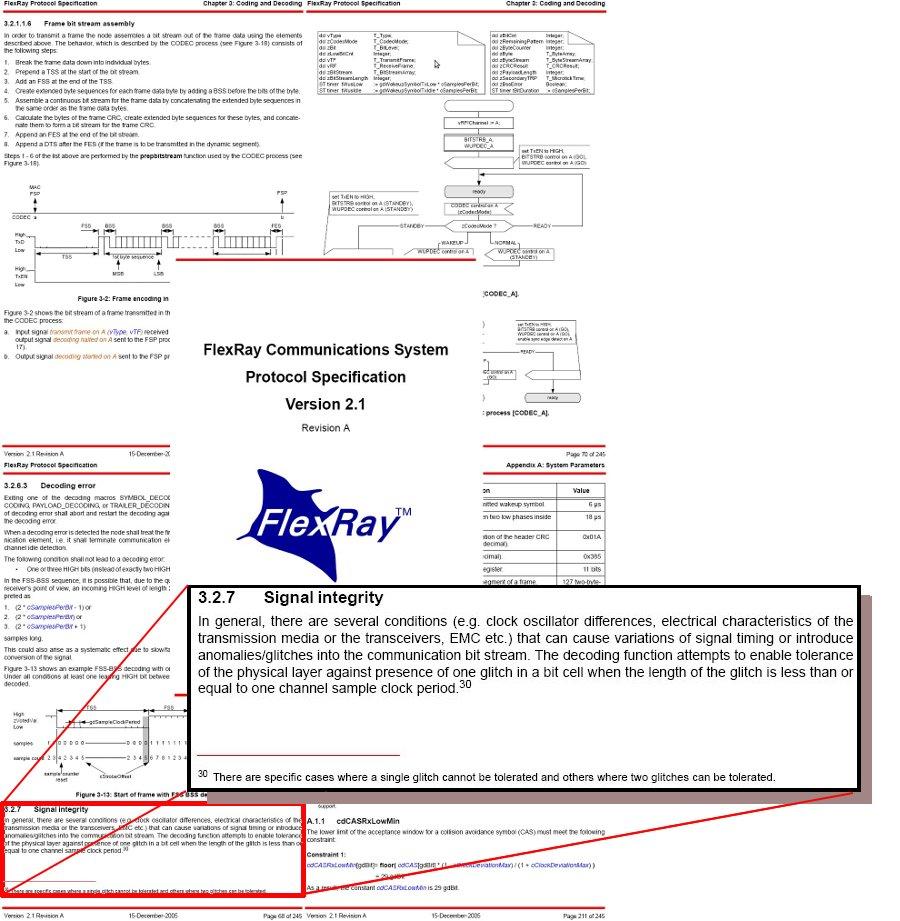
68 Glitch Model: Glitch Patterns The protocol guarantees tolerance for 1 glitch in every sequence of 4 consecutive samples (1 out of 4) 2 glitches in every sequence of 88 consecutive samples (2 out of 88) Note: one message samples
69 Glitch Model: Glitch Patterns The protocol guarantees tolerance for 1 glitch in every sequence of 4 consecutive samples (1 out of 4) E.g.: glitches in every sequence of 88 consecutive samples (2 out of 88) Note: one message samples
70 Glitch Model: Glitch Patterns The protocol guarantees tolerance for 1 glitch in every sequence of 4 consecutive samples (1 out of 4) E.g.: glitches in every sequence of 88 consecutive samples (2 out of 88) Note: one message samples
71 Glitch Model: Glitch Patterns The protocol guarantees tolerance for 1 glitch in every sequence of 4 consecutive samples (1 out of 4) E.g.: glitches in every sequence of 88 consecutive samples (2 out of 88) Note: one message samples
72 Glitch Model: Glitch Patterns The protocol guarantees tolerance for 1 glitch in every sequence of 4 consecutive samples (1 out of 4) E.g.: glitches in every sequence of 88 consecutive samples (2 out of 88) Note: one message samples
73 Glitch Model: Glitch Patterns The protocol guarantees tolerance for 1 glitch in every sequence of 4 consecutive samples (1 out of 4) E.g.: glitches in every sequence of 88 consecutive samples (2 out of 88) Note: one message samples
74 Glitch Model: Glitch Patterns The protocol guarantees tolerance for 1 glitch in every sequence of 4 consecutive samples (1 out of 4) E.g.: glitches in every sequence of 88 consecutive samples (2 out of 88) Note: one message samples
75 Glitch Model: Glitch Patterns The protocol guarantees tolerance for 1 glitch in every sequence of 4 consecutive samples (1 out of 4) 2 glitches in every sequence of 88 consecutive samples (2 out of 88) Note: one message samples
76 Glitch Model: Glitch Patterns The protocol guarantees tolerance for 1 glitch in every sequence of 4 consecutive samples (1 out of 4) 2 glitches in every sequence of 88 consecutive samples (2 out of 88) E.g.: Note: one message samples
77 Glitch Tolerance vs. Voting Window Size Voting window size of 3, tolerates 1 glitch in every sequence of 3 consecutive samples. E.g.: , tolerates 1 glitch in every sequence of 4 consecutive samples. E.g.: , tolerates 1 glitch in every sequence of 5 consecutive samples. 9, tolerates 1 glitch in every sequence of 6 consecutive samples.
78 Glitch Tolerance vs. Voting Window Size Voting window size of 3, tolerates 1 glitch in every sequence of 3 consecutive samples. E.g.: , tolerates 1 glitch in every sequence of 4 consecutive samples. E.g.: , tolerates 1 glitch in every sequence of 5 consecutive samples. 9, tolerates 1 glitch in every sequence of 6 consecutive samples.
79 Glitch Tolerance vs. Voting Window Size Voting window size of 3, tolerates 1 glitch in every sequence of 3 consecutive samples. E.g.: , tolerates 1 glitch in every sequence of 4 consecutive samples. E.g.: , tolerates 1 glitch in every sequence of 5 consecutive samples. 9, tolerates 1 glitch in every sequence of 6 consecutive samples.
80 Glitch Tolerance vs. Voting Window Size Voting window size of 3, tolerates 1 glitch in every sequence of 3 consecutive samples. E.g.: , tolerates 1 glitch in every sequence of 4 consecutive samples. E.g.: , tolerates 1 glitch in every sequence of 5 consecutive samples. 9, tolerates 1 glitch in every sequence of 6 consecutive samples.
81 Glitch Tolerance vs. Voting Window Size Voting window size of 3, tolerates 1 glitch in every sequence of 3 consecutive samples. E.g.: , tolerates 1 glitch in every sequence of 4 consecutive samples. E.g.: , tolerates 1 glitch in every sequence of 5 consecutive samples. 9, tolerates 1 glitch in every sequence of 6 consecutive samples.
82 Glitch Tolerance vs. Voting Window Size Voting window size of 3, tolerates 1 glitch in every sequence of 3 consecutive samples. E.g.: , tolerates 1 glitch in every sequence of 4 consecutive samples. E.g.: , tolerates 1 glitch in every sequence of 5 consecutive samples. 9, tolerates 1 glitch in every sequence of 6 consecutive samples.
83 Bit flips: Real-Time Glitch Model: 1*Y during XX ReceiverCLK_0? RxIn = volt a := 0 RxIn := volt ReceiverCLK_0? Normal a > ERRDIST t SETUP HOLD A a := 0 RxIn := 2 A := false Glitch a < ERRDUR + SETUP + HOLD fresh clock a (clocks are always initialised with 0) A: flag saying there was no glitch so far (initialized with true) ERRDIST t : distance from the last error ERRDUR: maximal duration of an disturbance on the bus volt: value from the bus, with 1=HIGH, 0=LOW, and 2=undefined RxIn: value seen by receiver
84 Bit flips: Real-Time Glitch Model: 2*Y indep. during XX ReceiverCLK_0? RxIn = volt a := 0 RxIn := volt ReceiverCLK_0? Normal a > ERRDIST t SETUP HOLD A a := 0 RxIn := 2 A := false GlitchA a < ERRDUR + SETUP + HOLD b > ERRDIST t SETUP HOLD B b := 0 RxIn := 2 B := false b := 0 RxIn := volt GlitchB b < ERRDUR + SETUP + HOLD ReceiverCLK_0? fresh clocks a and b (clocks are always initialised with 0) A(B): flag saying there was no glitch A (glitch B) so far (initialized with true) ERRDIST t : distance from the last error volt: value from the bus, with 1=HIGH, 0=LOW, and 2=undefined RxIn: value seen by receiver
85 Parameter Exploration Parameter exploration using binary search: boundaries for variation of a single parameter (Voting window size 5) glitch tolerance delay variance (1 of 4),(2 at most),(short Real-Time Glitch (RTG)) 1.435ns ns (2 (adj./ind.) of 88),(long RTG),(2 ind. short RTGs) 1.435ns ns (1 at most) 1.435ns ns deviation of clock glitch tolerance from standard rate (1 of 4),(2 at most),(short RTG) 0.15% 0.46% (2 ind. of 88),(2 ind. short RTGs) 0.15% 0.40% (2 adj. of 88),(long RTG) 0.15% 0.45% (1 at most) 0.15% 1.09% (no glitches) 0.15% 1.74% (RTGs configured to be equivalent to the respective Sample Glitches)
86 Summary:Our Approach Model the physical layer protocol (it is interfacing with the hardware) To model effects happening in dense time, use extended timed automata. Parameterize the model. (especially hardware) Plug in an error model. (Simulate with UPPAALto debug the model and improve insight) Model check reachability of error state with UPPAAL. ( & Find error scenarios missed by testing very fast ) Explore the effect of changing a parameter.
87 Summary:Model Design Principles Separate the protocol into components. Abstract from time where order suffices. You need time? Ignore constant delays if communication is one-way only. Reduce the number of clocks by exploiting dependencies. Nondeterminism allows you to forget message information (content, length, format). Use a parameterized hardware model for easy adoption to different hardware.
Automated Formal Methods for Embedded Systems
 Automated Formal Methods for Embedded Systems Bernd Finkbeiner Universität des Saarlandes Reactive Systems Group 2011/02/03 Bernd Finkbeiner (UdS) Embedded Systems 2011/02/03 1 / 48 Automated Formal Methods
FlexRay for Avionics: Automatic Verification with Parametric Physical Layers
 FlexRay for Avionics: Automatic Verification with Parametric Physical Layers Michael Gerke, Rüdiger Ehlers, Bernd Finkbeiner, and Hans-Jörg Peter Reactive Systems Group, Saarland University, 66123 Saarbrücken,
Model Checking the FlexRay Physical Layer Protocol
 Model hecking the FlexRay Physical Layer Protocol Michael Gerke, Rüdiger Ehlers, Bernd Finkbeiner, and Hans-Jörg Peter Reactive Systems Group Saarland University 66123 Saarbrücken, Germany {gerke ehlers
ISO INTERNATIONAL STANDARD. Road vehicles FlexRay communications system Part 2: Data link layer specification
 INTERNATIONAL STANDARD ISO 17458-2 First edition 2013-02-01 Road vehicles FlexRay communications system Part 2: Data link layer specification Véhicules routiers Système de communications FlexRay Partie
This document is a preview generated by EVS
 INTERNATIONAL STANDARD ISO 17458-2 First edition 2013-02-01 Road vehicles FlexRay communications system Part 2: Data link layer specification Véhicules routiers Système de communications FlexRay Partie
CAN protocol enhancement
 Protocols CAN protocol enhancement This article describes the enhanced CAN protocol called CAN-HG and the features of the IC circuitry from Canis that implement it. CAN-HG has been designed to meet two
CAN in Space workshop
 CAN in Space workshop Holger Zeltwanger www.can-cia.org The next generation of CAN technology: Chances and challenges of CAN FD Presentation outline u Introduction into CAN FD u CAN FD physical layer u
An Encapsulated Communication System for Integrated Architectures
 An Encapsulated Communication System for Integrated Architectures Architectural Support for Temporal Composability Roman Obermaisser Overview Introduction Federated and Integrated Architectures DECOS Architecture
Direct Link Networks: Building Blocks (2.1), Encoding (2.2), Framing (2.3)
, Encoding (2.2), Framing (2.3)") Direct Link Networks: Building Blocks (2.1), Encoding (2.2), Framing (2.3) ECPE/CS 5516: Computer Networks Originally by Scott F. Midkiff (ECpE) Modified by Marc Abrams (CS) Virginia Tech courses.cs.vt.edu/~cs5516
Direct Link Networks: Building Blocks (2.1), Encoding (2.2), Framing (2.3) ECPE/CS 5516: Computer Networks Originally by Scott F. Midkiff (ECpE) Modified by Marc Abrams (CS) Virginia Tech courses.cs.vt.edu/~cs5516
FlexRay International Workshop. Protocol Overview
 FlexRay International Workshop 4 th March 2003 Detroit Protocol Overview Dr. Christopher Temple - Motorola FlexRay principles Provide a communication infrastructure for future generation highspeed control
ECE 353 Lab 4. MIDI Receiver in Verilog. Professor Daniel Holcomb UMass Amherst Fall 2016
 ECE 353 Lab 4 MIDI Receiver in Verilog Professor Daniel Holcomb UMass Amherst Fall 2016 Timeline and Grading for Lab 4 Lectures on 11/15 and 11/17 Due on 12/12 Demos in Duda hall Schedule will be posted
FlexRay controller. Author: Martin Paták
 FlexRay controller Author: Martin Paták Prague, 2012 Contents 1 FlexRay controller 1 1.1 Overview.................................... 1 1.2 Interface.................................... 2 1.2.1 Overview...............................
Various Emerging Time- Triggered Protocols for Driveby-Wire
 Various Emerging Time- Triggered for Driveby-Wire Applications Syed Masud Mahmud, Ph.D. Electrical and Computer Engg. Dept. Wayne State University Detroit MI 48202 smahmud@eng.wayne.edu January 11, 2007
Additional Slides (informative)
") Automation Systems Discrete Event Control Systems and Networked Automation Systems Additional Slides (informative) Application Automotive Networks (LIN, CAN, FlexRay, MOST) Vorlesungstitel Vehicle Bus
Automation Systems Discrete Event Control Systems and Networked Automation Systems Additional Slides (informative) Application Automotive Networks (LIN, CAN, FlexRay, MOST) Vorlesungstitel Vehicle Bus
Links, clocks, optics and radios
 Links, clocks, optics and radios end IP addresses Source Destination Data 171.64.74.55 176.22.45.66 176 10110000 start Example of On-Off Keying +5V 0V Volts 1 0 time Data 0 1 1 0 0 1 0 1 1 0 1 0 1 0
Field buses (part 2): time triggered protocols
: time triggered protocols") Field buses (part 2): time triggered protocols Nico Fritz Universität des Saarlandes Embedded Systems 2002/2003 (c) Daniel Kästner. 1 CAN and LIN LIN CAN Type Arbitration Transfer rate Serial communication
Field buses (part 2): time triggered protocols Nico Fritz Universität des Saarlandes Embedded Systems 2002/2003 (c) Daniel Kästner. 1 CAN and LIN LIN CAN Type Arbitration Transfer rate Serial communication
Distributed Systems (ICE 601) Fault Tolerance
 Fault Tolerance") Distributed Systems (ICE 601) Fault Tolerance Dongman Lee ICU Introduction Failure Model Fault Tolerance Models state machine primary-backup Class Overview Introduction Dependability availability reliability
Distributed Systems (ICE 601) Fault Tolerance Dongman Lee ICU Introduction Failure Model Fault Tolerance Models state machine primary-backup Class Overview Introduction Dependability availability reliability
Links. CS125 - mylinks 1 1/22/14
 Links 1 Goals of Today s Lecture Link-layer services Encoding, framing, and error detection Error correction and flow control Sharing a shared media Channel partitioning Taking turns Random access Shared
Sequential Circuit Design: Principle
 Sequential Circuit Design: Principle Chapter 8 1 Outline 1. Overview on sequential circuits 2. Synchronous circuits 3. Danger of synthesizing asynchronous circuit 4. Inference of basic memory elements
Framing and Stuffing. Advanced Computer Networks
 Framing and Stuffing Advanced Computer Networks Framing & Stuffing Outline Synchronous vs Asynchronous Transmissions Asynchronous Character Transmissions Framing Identifying Synchronous Block Boundaries
Organization. 5.1 Semiconductor Main Memory. William Stallings Computer Organization and Architecture 6th Edition
 William Stallings Computer Organization and Architecture 6th Edition Chapter 5 Internal Memory 5.1 Semiconductor Main Memory 5.2 Error Correction 5.3 Advanced DRAM Organization 5.1 Semiconductor Main Memory
CS 43: Computer Networks Switches and LANs. Kevin Webb Swarthmore College December 5, 2017
 CS 43: Computer Networks Switches and LANs Kevin Webb Swarthmore College December 5, 2017 Ethernet Metcalfe s Ethernet sketch Dominant wired LAN technology: cheap $20 for NIC first widely used LAN technology
FlexRay. Requirements Specification. Version 2.1
 FlexRay Requirements Specification Version 2.1. Revision History DISCLAIMER This specification as released by the FlexRay Consortium is intended for the purpose of information only. The use of material
Lecture 3: Modulation & Layering"
 Lecture 3: Modulation & Layering" CSE 123: Computer Networks Alex C. Snoeren HW 1 out Today, due 10/09! Lecture 3 Overview" Encoding schemes Shannon s Law and Nyquist Limit Clock recovery Manchester, NRZ,
FlexRay and Automotive Networking Future
 FlexRay and Automotive Networking Future Chris Quigley Warwick Control Technologies Presentation Overview High Speed and High Integrity Networking Why FlexRay? CAN Problems Time Triggered Network Principles
Communication Networks for the Next-Generation Vehicles
 Communication Networks for the, Ph.D. Electrical and Computer Engg. Dept. Wayne State University Detroit MI 48202 (313) 577-3855, smahmud@eng.wayne.edu January 13, 2005 4 th Annual Winter Workshop U.S.
LECTURE # 8. Bad Technology Flow control, error control, addressing is multiple Session and Presentation(EMPTY), Network and DL(Full)
, Network and DL(Full)") Critique of OSI Model LECTURE # 8 Reasoning for OSI not getting Widespread Bad Timing(slide) (Apocalypse of Two Elephants) David Clarke of MIT If standards are written too early: subject is badly understood
Critique of OSI Model LECTURE # 8 Reasoning for OSI not getting Widespread Bad Timing(slide) (Apocalypse of Two Elephants) David Clarke of MIT If standards are written too early: subject is badly understood
An Introduction to FlexRay as an Industrial Network
 An Introduction to FlexRay as an Industrial Network Robert Shaw, Brendan Jackman Automotive Control Group, Waterford Institute of Technology, Waterford, Ireland. E-mail: rshaw@wit.ie, bjackman@wit.ie Website:
Comparison of In-Vehicle Communication Protocols for Critical Applications
 IVSS-2005-ARC-03 Comparison of In-Vehicle Communication Protocols for Critical Applications Edward Robert Gundlach and Syed Masud Mahmud Electrical and Computer Engineering Department, Wayne State University,
16 Time Triggered Protocol
 16 Time Triggered Protocol [TTtech04] (TTP) 18-549 Distributed Embedded Systems Philip Koopman October 25, 2004 Significant material drawn from: Prof. H. Kopetz [Kopetz] TTP Specification v 1.1 [TTTech]
Sequential Circuit Design: Principle
 Sequential Circuit Design: Principle Chapter 8 1 Outline 1. Overview on sequential circuits 2. Synchronous circuits 3. Danger of synthesizing async circuit 4. Inference of basic memory elements 5. Simple
Laboratory Finite State Machines and Serial Communication
 Laboratory 11 11. Finite State Machines and Serial Communication 11.1. Objectives Study, design, implement and test Finite State Machines Serial Communication Familiarize the students with Xilinx ISE WebPack
Discussion of Failure Mode Assumptions for IEEE 802.1Qbt
 Discussion of Failure Mode Assumptions for IEEE 802.1Qbt Wilfried Steiner, Corporate Scientist wilfried.steiner@tttech.com www.tttech.com Page 1 Clock Synchronization is a core building block of many RT
DS28CM00. I²C/SMBus Silicon Serial Number
 DS28CM00 I²C/SMBus Silicon Serial Number www.maxim-ic.com GENERAL DESCRIPTION The DS28CM00 is a low-cost, electronic registration number to provide an absolutely unique identity that can be determined
The Timed Asynchronous Distributed System Model By Flaviu Cristian and Christof Fetzer
 The Timed Asynchronous Distributed System Model By Flaviu Cristian and Christof Fetzer - proposes a formal definition for the timed asynchronous distributed system model - presents measurements of process
Simulation based Timing Analysis of FlexRay Communication at System Level. Stefan Buschmann Till Steinbach Franz Korf Thomas C.
 Simulation based Timing Analysis of FlexRay Communication at System Level Stefan Buschmann Till Steinbach Franz Korf Thomas C. Schmidt stefan.buschmann@haw-hamburg.de {till.steinbach, korf, schmidt}@informatik.haw-hamburg.de
Lecture 5: Data Link Layer Basics
 Lecture 5: Data Link Layer Basics Dr. Mohammed Hawa Electrical Engineering Department University of Jordan EE426: Communication Networks Layer 2 PDU: Frame 2 1 Bit-oriented vs. Byte-oriented Layer 2 protocols
SEE Tolerant Self-Calibrating Simple Fractional-N PLL
 SEE Tolerant Self-Calibrating Simple Fractional-N PLL Robert L. Shuler, Avionic Systems Division, NASA Johnson Space Center, Houston, TX 77058 Li Chen, Department of Electrical Engineering, University
MicroBlaze TFTP Server User Guide
 Lorne Applebaum appleba@eecg.utoronto.ca August 25, 2004 1 Preamble This document describes the intended method of use for the MicroBlaze TFTP Server. For detailed information regarding how the server
Chapter 39: Concepts of Time-Triggered Communication. Wenbo Qiao
 Chapter 39: Concepts of Time-Triggered Communication Wenbo Qiao Outline Time and Event Triggered Communication Fundamental Services of a Time-Triggered Communication Protocol Clock Synchronization Periodic
RTL Power Estimation and Optimization
 Power Modeling Issues RTL Power Estimation and Optimization Model granularity Model parameters Model semantics Model storage Model construction Politecnico di Torino Dip. di Automatica e Informatica RTL
MMC-2 CD MODEL. Document Number R0 File name MM2-05r0.doc. Content: Clause 5 of SFF CD Model
 Document Number 97-104R0 File name MM2-05r0.doc MMC-2 CD MODEL Content: Clause 5 of SFF8090-.09 CD Model Technical Editor: Ron Roberts Sierra-Pac Technology PO Box 2389 Shingle Springs, CA 95682 E-mail:
Data Link Layer Overview
 Data Link Layer Overview First of four classes on the data link layer Internet Architecture Bottom up: Physical: electromagnetic signals on the wire Link: data transfer between neighboring network elements
Help Volume Agilent Technologies. All rights reserved. Agilent E2485A Memory Expansion Interface
 Help Volume 1994-2002 Agilent Technologies. All rights reserved. Agilent E2485A Memory Expansion Interface Agilent E2485A Memory Expansion Interface The E2485A Memory Expansion Interface lets you use the
OUTLINE Introduction Power Components Dynamic Power Optimization Conclusions
 OUTLINE Introduction Power Components Dynamic Power Optimization Conclusions 04/15/14 1 Introduction: Low Power Technology Process Hardware Architecture Software Multi VTH Low-power circuits Parallelism
Kun Sun, Peng Ning Cliff Wang An Liu, Yuzheng Zhou
 Kun Sun, Peng Ning Cliff Wang An Liu, Yuzheng Zhou Abstract Accurate and synchronized time is crucial in many sensor network applications Time synchronization becomes an attractive target due to its importance
The Flooding Time Synchronization Protocol
 The Flooding Time Synchronization Protocol Miklos Maroti, Branislav Kusy, Gyula Simon and Akos Ledeczi Vanderbilt University Contributions Better understanding of the uncertainties of radio message delivery
Tektronix DPO Demo 1 Board Instruction Manual
 xx ZZZ Tektronix DPO Demo 1 Board Instruction Manual www.tektronix.com *P071253900* 071-2539-00 Copyright Tektronix. All rights reserved. Licensed software products are owned by Tektronix or its subsidiaries
William Stallings Computer Organization and Architecture 6th Edition. Chapter 5 Internal Memory
 William Stallings Computer Organization and Architecture 6th Edition Chapter 5 Internal Memory Semiconductor Memory Types Semiconductor Memory RAM Misnamed as all semiconductor memory is random access
CMPE 150/L : Introduction to Computer Networks. Chen Qian Computer Engineering UCSC Baskin Engineering Lecture 18
 CMPE 150/L : Introduction to Computer Networks Chen Qian Computer Engineering UCSC Baskin Engineering Lecture 18 1 Final project demo Please do the demo THIS week to the TAs. Or you are allowed to use
CAN FD with Dynamic Multi-PDU-to-Frame Mapping
 CAN FD with Dynamic Multi-PDU-to-Frame Mapping Flexible Network Architectures V0.1 2015-09-25 E/E Trends and Challenges Why is Dynamic Multi-PDU-to-Frame Mapping required? The Trend: Demand for communication
Chapter 5 Internal Memory
 Chapter 5 Internal Memory Memory Type Category Erasure Write Mechanism Volatility Random-access memory (RAM) Read-write memory Electrically, byte-level Electrically Volatile Read-only memory (ROM) Read-only
Embedded Systems. 8. Communication
 Embedded Systems 8. Communication Lothar Thiele 8-1 Contents of Course 1. Embedded Systems Introduction 2. Software Introduction 7. System Components 10. Models 3. Real-Time Models 4. Periodic/Aperiodic
AVB in Automotive Infotainment Networks
 AVB in Automotive Infotainment Networks Günter Dannhäuser, Daimler AG Andrew Lucas, XMOS Ltd. 2014 IEEE-SA ETHERNET & IP @ AUTOMOTIVE TECHNOLOGY DAY COBO Center, Detroit, Michigan, USA 23 24 October 2014
Troubleshooting Ethernet Problems with Your Oscilloscope APPLICATION NOTE
 Troubleshooting Ethernet Problems with Your Oscilloscope Introduction Ethernet is a family of frame-based computer networking technologies for local area networks (LANs), initially developed at Xerox PARC
CSCI-1680 Link Layer I Rodrigo Fonseca
 CSCI-1680 Link Layer I Rodrigo Fonseca Based partly on lecture notes by David Mazières, Phil Levis, John Jannotti Last time Physical layer: encoding, modulation Today Link layer framing Getting frames
Data Link Layer Overview
 Data Link Layer Overview : 9/7/2007 CSC 257/457 - Fall 2007 1 Internet Architecture Bottom-up: physical: electromagnetic signals on the wire link: data transfer between neighboring network elements network:
RPLIDAR. Interface Protocol and Application Notes. Low Cost 360 Degree Laser Range Scanner. Applied to RPLIDAR A1 & A rev.1.
 RPLIDAR 2017-05-15 rev.1.0 Low Cost 360 Degree Laser Range Scanner Interface Protocol and Application Notes Applied to RPLIDAR A1 & A2 ww w.slam tec.com Shanghai Slam tec.c o.,ltd Contents CONTENTS...
Using UART in radio data transmission with the CDP-02 module By Tomihiko Uchikawa
 Using UART in radio data transmission with the CDP-02 module By Tomihiko Uchikawa Abstract: The first time a customer uses the CDP-TX-02N/RX-02N (called CDP-02 module) radio module, they are often uncertain
Today. Last Time. Motivation. CAN Bus. More about CAN. What is CAN?
 Embedded networks Characteristics Requirements Simple embedded LANs Bit banged SPI I2C LIN Ethernet Last Time CAN Bus Intro Low-level stuff Frame types Arbitration Filtering Higher-level protocols Today
CE3005: Computer Networks Laboratory 3 SNIFFING AND ANALYSING NETWORK PACKETS
 SNIFFING AND ANALYSING NETWORK PACKETS 1. OBJECTIVE To further understand how the Internet really works and how the concept of encapsulation is being implemented in the different layers of the TCP/IP protocol
FlexRay Requirements Specification
 FlexRay - Requirements Specification FlexRay Requirements Specification Authors: Ralf Belschner 2, Josef Berwanger 1, Christian Ebner 1, Harald Eisele 4, Sven Fluhrer 2, Thomas Forest 4, Thomas Führer
CS 344/444 Computer Network Fundamentals Final Exam Solutions Spring 2007
 CS 344/444 Computer Network Fundamentals Final Exam Solutions Spring 2007 Question 344 Points 444 Points Score 1 10 10 2 10 10 3 20 20 4 20 10 5 20 20 6 20 10 7-20 Total: 100 100 Instructions: 1. Question
Lecture 6 The Data Link Layer. Antonio Cianfrani DIET Department Networking Group netlab.uniroma1.it
 Lecture 6 The Data Link Layer Antonio Cianfrani DIET Department Networking Group netlab.uniroma1.it Link Layer: setting the context two physically connected devices: host-router, router-router, host-host,
Hello, and welcome to this presentation of the STM32 Universal Synchronous/Asynchronous Receiver/Transmitter Interface. It covers the main features
 Hello, and welcome to this presentation of the STM32 Universal Synchronous/Asynchronous Receiver/Transmitter Interface. It covers the main features of this USART interface, which is widely used for serial
WiMOD LR Base Host Controller Interface
 WiMOD LR Base Host Controller Interface Specification Version 1.7 Document ID: 4100/40140/0062 IMST GmbH Carl-Friedrich-Gauß-Str. 2-4 47475 KAMP-LINTFORT GERMANY Introduction Document Information File
Sharif University of Technology, Tehran, Iran
 EVALUATION OF BABBLING IDIOT FAILURES IN FLEXRAY-BASED NETWORKES * Vahid Lari, Mehdi Dehbashi, Seyed Ghassem Miremadi, Mojtaba Amiri Sharif University of Technology, Tehran, Iran Abstract: This paper evaluates
COMP asynchronous buses April 5, 2016
 All the I/O examples we have discussed use the system bus to send data between the CPU, main memory, and I/O controllers. The system bus runs at a slower clock speed than the CPU because of greater distances
EECS150 - Digital Design Lecture 20 - Finite State Machines Revisited
 EECS150 - Digital Design Lecture 20 - Finite State Machines Revisited April 2, 2009 John Wawrzynek Spring 2009 EECS150 - Lec20-fsm Page 1 Finite State Machines (FSMs) FSM circuits are a type of sequential
Module 8 - Fault Tolerance
 Module 8 - Fault Tolerance Dependability Reliability A measure of success with which a system conforms to some authoritative specification of its behavior. Probability that the system has not experienced
Redundant States in Sequential Circuits
 Redundant States in Sequential Circuits Removal of redundant states is important because Cost: the number of memory elements is directly related to the number of states Complexity: the more states the
e-pg Pathshala Subject : Computer Science Paper: Embedded System Module: Serial Port Communication Module No: CS/ES/11 Quadrant 1 e-text
 e-pg Pathshala Subject : Computer Science Paper: Embedded System Module: Serial Port Communication Module No: CS/ES/11 Quadrant 1 e-text In this lecture, serial port communication will be discussed in
Amrita Vishwa Vidyapeetham. ES623 Networked Embedded Systems Answer Key
 Time: Two Hours Amrita Vishwa Vidyapeetham M.Tech Second Assessment February 2013 Second Semester Embedded Systems Roll No: ES623 Networked Embedded Systems Answer Key Answer all Questions Maximum: 50
Links Reading: Chapter 2. Goals of Todayʼs Lecture. Message, Segment, Packet, and Frame
 Links Reading: Chapter 2 CS 375: Computer Networks Thomas Bressoud 1 Goals of Todayʼs Lecture Link-layer services Encoding, framing, and error detection Error correction and flow control Sharing a shared
IP SLAs QFP Time Stamping
 This module describes how to configure the IP SLA QFP Time Stamping feature for IP Service Level Agreements (SLAs) UDP jitter operations. This new probe and responder structure enables more accurate network
Data Link Technology. Suguru Yamaguchi Nara Institute of Science and Technology Department of Information Science
 Data Link Technology Suguru Yamaguchi Nara Institute of Science and Technology Department of Information Science Agenda Functions of the data link layer Technologies concept and design error control flow
FlexRay - FlexRay Synchronization with CANoe as Gateway
 FlexRay - FlexRay Synchronization with CANoe as Gateway Version 2.0 2017-06-12 Application Note AN-IND-1-010 Author Restrictions Abstract Vector Informatik GmbH Public Document Time synchronization is
Basics of UART Communication
 Basics of UART Communication From: Circuit Basics UART stands for Universal Asynchronous Receiver/Transmitter. It s not a communication protocol like SPI and I2C, but a physical circuit in a microcontroller,
CSMC 417. Computer Networks Prof. Ashok K Agrawala Ashok Agrawala Set 4. September 09 CMSC417 Set 4 1
 CSMC 417 Computer Networks Prof. Ashok K Agrawala 2009 Ashok Agrawala Set 4 1 The Data Link Layer 2 Data Link Layer Design Issues Services Provided to the Network Layer Framing Error Control Flow Control
Advantages and disadvantages
 Advantages and disadvantages Advantages Disadvantages Asynchronous transmission Simple, doesn't require synchronization of both communication sides Cheap, timing is not as critical as for synchronous transmission,
CAN with Flexible Data-Rate
 CAN with Flexible Data-Rate Florian Hartwich, Robert Bosch GmbH Ever increasing bandwidth requirements in automotive networks impede the applicability of CAN due to its bit rate limitation to 1 MBit/s.
Development of a CAN Slave Module with SystemC. Igor Sachs Shang Qihua
 Development of a CAN Slave Module with SystemC Igor Sachs Shang Qihua Agenda 0. Motivation 1. Introduction to the CAN-Bus 1.1 The CAN Message Format (Frame) 1.2 Bus Arbitration 1.3 Bit Stuffing 2. Development
DS1676 Total Elapsed Time Recorder, Erasable
 www.dalsemi.com Preliminary DS1676 Total Elapsed Time Recorder, Erasable FEATURES Records the total time that the Event Input has been active and the number of events that have occurred. Volatile Elapsed
Keysight M8070A System Software for M8000 Series of BER Test Solutions
 Keysight M8070A System Software for M8000 Series of BER Test Solutions Release Notes The M8070A system software for the M8000 Series of BER Test Solutions is required to control M8041A, M8051A and M8061A.
Data Link Layer Overview
 Data Link Layer Overview First of four classes on the data link layer Internet Architecture Bottom up: Physical: electromagnetic signals on the wire Link: data transfer between neighboring network elements
ECE 4450:427/527 - Computer Networks Spring 2017
 ECE 4450:427/527 - Computer Networks Spring 2017 Dr. Nghi Tran Department of Electrical & Computer Engineering Lecture 5.1: Link Layer Dr. Nghi Tran (ECE-University of Akron) ECE 4450:427/527 Computer
Optical Data Interface ODI-2.1 High Speed Data Formats Preliminary Specification. Revision Date
 Optical Data Interface O-2.1 High Speed Data Formats Preliminary Specification Revision Date 171002 2 O 3-part Specification O-2.1: High-Speed Formats 8 to 16 bit data formats Packing Methods Optimized
15-740/ Computer Architecture Lecture 19: Main Memory. Prof. Onur Mutlu Carnegie Mellon University
 15-740/18-740 Computer Architecture Lecture 19: Main Memory Prof. Onur Mutlu Carnegie Mellon University Last Time Multi-core issues in caching OS-based cache partitioning (using page coloring) Handling
Distributed IMA with TTEthernet
 Distributed IMA with thernet ARINC 653 Integration of thernet Georg Gaderer, Product Manager Georg.Gaderer@tttech.com October 30, 2012 Copyright TTTech Computertechnik AG. All rights reserved. Introduction
ProgRock Operating manual _Pr1.01a_
 1. Introduction ProgRock Operating manual _Pr1.01a_ This is the operating manual for the ProgRock synthesiser kit. It should be read together with the assembly instructions for the ProgRock kit and Si5351A
Freescale and the Freescale logo are trademarks of Freescale Semiconductor, Inc. All other product or service names are the property of their
 S08 Highlighted Features Why Do I Need a Slave LIN Interface Controller (SLIC)? Design Challenges Slave synchronization Slave synchronizing to LIN messaging requires a cost versus resource trade-off. Your
Troubleshooting Ethernet Problems with Your Oscilloscope APPLICATION NOTE
 Troubleshooting Ethernet Problems with Your Oscilloscope Introduction Ethernet is a family of frame-based computer networking technologies for local area networks (LANs), initially developed at Xerox PARC
Data Link Layer. Indian Institute of Technology Madras
 Data Link Layer Study of algorithms for achieving reliable, efficient communication between two adjacent machines at DLL. adjacent - two machines physically connected using a communication channel that
CHAPTER 4 DATA COMMUNICATION MODES
 USER S MANUAL CHAPTER DATA COMMUNICATION MODES. INTRODUCTION The SCC provides two independent, full-duplex channels programmable for use in any common asynchronous or synchronous data communication protocol.
Signals and Encoding
 Signals and Encoding 18 Signals and Encoding You can design and program a USB peripheral without knowing all of the details about how the data is encoded on the bus. But understanding something about these
Module 6 STILL IMAGE COMPRESSION STANDARDS
 Module 6 STILL IMAGE COMPRESSION STANDARDS Lesson 19 JPEG-2000 Error Resiliency Instructional Objectives At the end of this lesson, the students should be able to: 1. Name two different types of lossy
Computer Systems Architecture I. CSE 560M Lecture 18 Guest Lecturer: Shakir James
 Computer Systems Architecture I CSE 560M Lecture 18 Guest Lecturer: Shakir James Plan for Today Announcements No class meeting on Monday, meet in project groups Project demos < 2 weeks, Nov 23 rd Questions
Direct Link Networks. Framing. Lecture - Encoding & Framing 1. Problems. Areas for Discussion
 Areas for Discussion Direct Link s Joseph Spring School of Computer Science 3COM0271 Computer Protocols & Architecture s Based on Chapter 2, Peterson & Davie, Computer s: A Systems Approach, 4 th Ed Problems
Help Volume Agilent Technologies. All rights reserved. Agilent Technologies 16741A Logic Analyzer
 Help Volume 1992-2002 Agilent Technologies. All rights reserved. Agilent Technologies 16741A Logic Analyzer Agilent Technologies 16741A Logic Analyzer The Agilent Technologies 16741A 200 MHz State/2 GHz
Testing SyncE with Xena s Advanced Timing Test Modules
 Testing SyncE with Xena s Advanced Timing Test Modules Rev 1 How to use Xena s Advanced Timing test modules to demonstrate network synchronization, and to perform go/no-go testing of SyncE networks. APPLICATION