Transmission SIGNALs
|
|
|
- Clementine Holt
- 5 years ago
- Views:
Transcription
1 Chapter 6 Digital Communications Basics 6.1 Introduction 6.2 Transmission media 6.3 Source of signal impairment 6.4 Asynchronous Transmission 6.5 Synchronous Transmission 6.6 Error Detection Methods 6.7 Protocol basics 6.8 The HDLC protocol
2 Transmission SIGNALs Physical layer manage the moving information in the form of electromagnetic across network connection information voice, image, numeric data, characters, or video collecting information from computer sending information from computer use encoder/decoder to create/reconstruct a stream of 1s and 0s converts a form to transfer via transmission media» the form of electromagnetic signals
3 Analog and Digital Signal Analog refers to something that is continuous Digital refers to something that is discrete Text, Voice, Video Image, etc Encoder Digital Information Analog
4 6.1 Introduction Baseband transmission : digital interface via NIC in LAN,ISDN

5 Modulated transmission Modulated transmission : analog transmission in PSTN
6 Effect of attenuation, distortion, and noise on transmitted signal Attenuated: decreased in amplitude distorted: misshappen noise
7 6.2 Transmission media (1) (a) Two-wire and multiwire open line (b) Unshielded twisted pair
 (b)")
 Coaxial")
8 6.2 Transmission media (2) (b) Shielded twisted pair (d) Coaxial cable
9 6.2.4 Optical fiber Transmission media (1) Cable structures
10 Transmission modes Optical fiber Transmission media (2)
11 6.2.5 Satellites Broadcast television Data communications

12 6.2.7 Ground-based Radio transmission Single cell Multiple cells
13 6.3 Sources of signal impairment
14 6.4 Digital Data Transmission Digital data Transmission Parallel Serial Synchronous Asynchronous

15 Parallel and Serial Transmission
16 Parallel and Serial Transmission (2) All transfer that are external to the system» are carried out bit-serially NIC must perform the following functions parallel-to-serial conversion of each character serial-to-parallel conversion of each received character achieve bit, character, and frame synchronization in receiver generate a suitable error check digits
17 Asynchronous and Synchronous transmission Asynchronous transmission Synchronous transmission

18 Asynchronous transmission Send one start bit (0) at beginning and one or more stop bits (1s) at the end of each byte may be a gap between each byte means asynchronous at the byte level but the bits are still synchronized

19 Synchronous transmission Send bits one after another without start/stop bits or gaps is the responsibility of the receiver to group the bits

20 6.4 Asynchronous Transmission (1) Principle of operation Timing principle
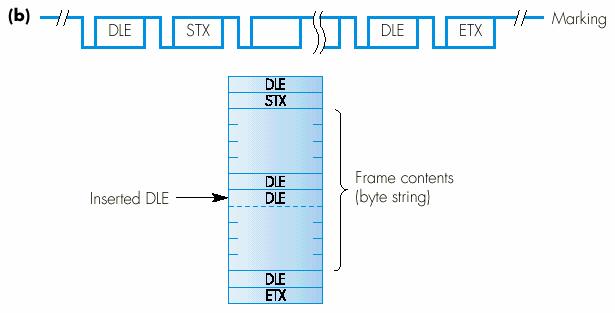
21 6.4 Asynchronous Transmission (2) Bit synchronization one start bit and two stop bits clock cycle (Figure 6.12) Character synchronization buffer register using one start bit and two stop bits Frame synchronization start-of-text (STX) character end-of-text (ETX) character data link escape (DLE) character to overcome an abnormally termination by an ETX character in receive processing
22 Figure 6.12 Examples of three different receiver clock rate ratios (a) x1, (b) x4, x16
23
 Two")

24 6.5 Synchronous Transmission (1) Two Synchronous Transmission Character-oriented Bit-oriented
25 6.5 Synchronous Transmission (2) Character-oriented sync SYN character STX, ETX, DLE character Bit-oriented sync an unique 8-bit pattern flag byte or flag pattern idle byte
26 Character-oriented sync

27 Bit-oriented sync
28 Encoding
29 Digital-to-Digital Encoding (1) Encoding the transmitted data into the binary 1s and 0s a sequence of voltage pulses Digital/digital Encoding Types of digital-to-digital encoding Uni-Polar: use only one technique Polar: use two of which have multiple variations» NRZ, RZ, biphase Bi-Polar: use three vairations» AMI, B8ZS, HDB3
30 Digital-to-Digital Encoding (2) Uni-polar encoding uses only one level of value (= one polarity) the polarity of a pulse : positive and negative one voltage level for binary 0 and 1» a valued voltage is 1, zero voltage is 0 two problems DC (Direct Current) Component Synchronization cannot change in voltage level to indicate the bit type
31 Digital-to-Digital Encoding (3) Polar uses two voltage levels (one positive and negative) of amplitude DC Component is eliminated by Manchester» binary 1: a negative-to-positive transition» binary 0: a positive-to-negative transition Types of polar encoding Non-Return to zero (NRZ) Non-Return to zero, Level (NRZ-L) Non-Return to zero, Invert (NRZ-L) Return to Zero (RZ) : Sync Biphasea: Sync Manchester Differential Manchester
32 Digital-to-Digital Encoding (4) 단류 NRZ방식 단류와복류는전압의 +/-까지의폭에있음. 비트값동안전압값을유지한다. 단점. 신호의동기에문제가있슴 NRZ-L NRZ-I
33 복류 RZ Digital-to-Digital Encoding (5) 전압 0 값을중심으로 +/- 를가짐 ( 복류 ) 데이터신호비트중간에서 0 으로전이되는신호화방식 + V V -V
34 Digital-to-Digital Encoding (6) Manchester +v/-v로끝나며, 신호의중간에서전이동기에유리 1은 -v 에서 +v 로끝나며, 0은 +v 에서 -v 로끝난다. Differential Manchester 1은 No transition, 0은 transition Manchester Differential Manchester
35 Digital-to-Digital Encoding (7) Bi-Polar like RZ; uses three voltage levels: +, -, zero unlike RZ zero level is binary 0 Three type Alternate Mark Inversion (AMI) the simplest type of bipolar encoding Bipolar 8-Zero Substitution (B8ZS) adopted in Noth America forces artificial changes, called violations within the 0 string High-Density Bipolar 3 (HDB3) used in Europe and Japan every time four consecutive 0 s
36 Digital-to-Digital Encoding (8) AMI (Alternate mark Inversion) zero voltage is binary 0 alternate is 1 inversion 앞의 1이 +v이면다음 1은 -v를가짐 + V AMI 0 V -V
37 6.6 Error detection methods Error Detection and Correction For reliable communication Data can be corrupted during transmission Errors must be detected and corrected Types of errors Data link layer Transport layer Single-Bit Error means that only one bit of a given data unit is changed Multiple-Bir Error means that two or or more nonconsecutive bits in a data unit have changed Burst Error means that two or more consecutive bits in a data unit have changed

38 Types of Errors
39 Detection (1) Error Detection uses the concept of redundancy, which means adding extra bits for detecting errors at the destination Detection Methods Vertical Redundancy Check (VRC) : called Parity check Longitudinal Redundancy Check (LRC) two dimension of VRC Cyclic Redundancy Check (CRC) Checksum VRC, LRC, CRC : are implemented in the physical layer for use in the data link layer Checksum: is implemented in the transport layer
40 Detection (2) Redundancy
41 VRC Called Parity Check a parity bit : a redundant bit is appended to every data unit so that the total number of 1s in the unit becomes either even or odd even parity : even odd parity: odd Reliability can detect all single-bit errors can detect multiple-bit or burst errors only if the total number of errors is odd ex: 6: > :9, :7, :5» 1 s are odd ---> rejected by VRC check ex: 6: > : 8, : 6, : 4» 1 s are even ----> accepted by VRC check
42 LRC To increase the detecting of multiple-bit and burst errors groups a predetermined number of data units, each already containing a VRC parity bit A redundant unit is added after a number of data units The bits in the redundant unit are calculated from the corresponding bits in the data units using VRC Reliability increases the detecting of multiple-bit and burst errors exist one pattern of errors if two bits in exactly the same positions ex two data units: and » and ( )
43 6.6.2 Block sum check (1)
44 6.6.3 CRC (1) Most powerful redundancy checking technique based on binary division (no bit addition) a sequence of redundant bits, called the CRC or the CRC remainder is appended to the end of a data unit the resulting data unit becomes exactly divisible by a predetermined binary number. At its destination,the incoming data unit is divided by the same number. If at this step no remainder,the data unit is assumed to be intact and is therefore accepted. A remainder indicates that the data unit has been damaged in transit and therefore must be rejected.
45 6.6.3 CRC (2) The redundancy bits used by CRC are derived by dividing the data unit by the pre-determined divisor binary division the remainder is the CRC. appending it to the end of the data
46 6.6.3 CRC (3) Reliability CRC will detect all possible errors except those that change the bit value of a block of code by exactly the value of the divisor. Popular CRC divisors, use I3,l7,and 33 bits,» the likelihood of an undetected error almost to zero. The CRC Generator uses modulo-2 division.or uses an algebraic polynomial ex: x 7 + x 5 + x 2 + x + 1 standard polynomials CRC-12: x 12 + x 11 + x 3 + x + 1 CRC-ITU: x 16 + x 12 + x 5 + 1
47 6.6.3 CRC (4)
48 Ref: Checksum (1) Checksum Generator subdivides the data unit into equal segments of n bits (usually l6) in the sender These segments are added together using one s complement arithmetic» the total is also n bits long Checksum That total(sum) appended to the end of the original data unit as redundancy bits,called the checksum The extended data unit is transmitted across the network so if the sum of the data segment is T,the checksum will be-t
49 Ref: Checksum (2)
50 Ref: Checksum (3) Checksum checker Reliability Checksum detects all errors involving odd numbers of bits,as well as most errors involving even numbers of bits. However, if one or more bits of a segment are damaged and the corresponding bit or bits of opposite value in a second segment are also damaged,» the sums of those columns will not change and the receiver will not detect a problem
51 Ref: Error Correction Two ways have the sender retransmit the entire data unit use an error-correcting code more sophisticated require more redundancy bits» limited to one, two, three-bit errors A single-bit error correction redundancy bits to indicate the location of the error bit data bits (m) + redundancy bits ( r) --> m + r bits different states : 2 r see table 9.1 : relationship between data and redundancy bits Hamming code

52 Ref: Hamming code Redundancy bits in Hamming code r1 : bit 1, 3, 4, 5, 9, 11 r2: bit 2, 3, 6, 7, 10, 11 r4: bit 4, 5, 6,7 r8: bit 8, 9, 10, 11
53 Ref: Redundancy bits calculation
54 Ref: Example of Redundancy bits calculation
55 Ref: Example

56 6.7 Protocol basics
57 6.7.1 Error Control Automatic Repeat Request (ARQ) Error control mechanism in data link layer Basic concepts anytime an error is detected in an exchange a negative acknowledgment (NAK) is returned the specified frames are retransmitted Error Control Idle RQ (Stop-and-wait ARQ) Continuous RQ (Sliding window ARQ) Go-back-N Selective repeat (Selective-reject)
58 Stop-and-wait ARQ, damaged frame
59 Stop-and-wait ARQ, lost ACK frame

60 Go-back-n, damaged data frame

61 Go-back-n, lost data frame
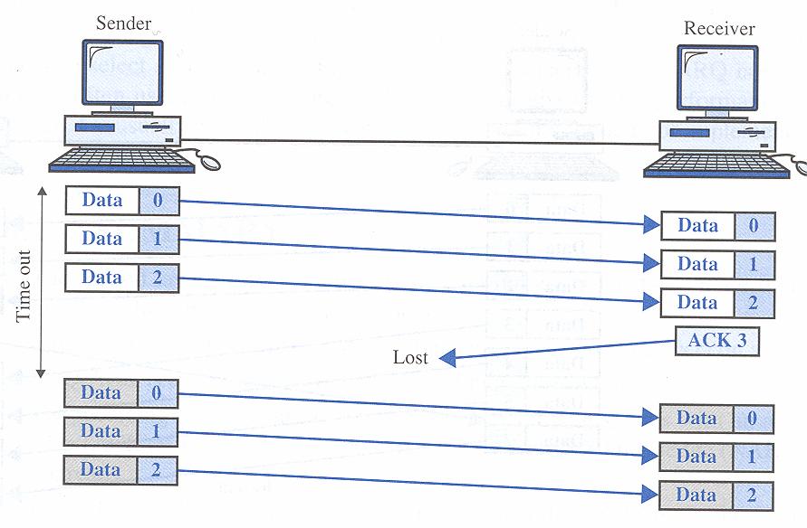
62 Go-back-n, lost ACK

63 Selective-reject, damaged data frame
64 6.7.4 Flow Control Flow Control refers to a set of procedures used to restrict the amount of data the sender can send before waiting for acknowledgment Two ways Stop-and-Wait Send one frame at a time the sender sends one frame and waits for an acknowledgement before sending the next frame Sliding Window Send several frames at a time several frames can be in transit at a time
65 Stop-and -Wait
66 Flow control principle via sliding window
67 Max. number for each protocol Sequence numbers in sliding window Example assuming 8 sequence numbers

68 Example of Sliding Windows

69 6.7.6 Layered architecture
70 6.8 The HDLC protocol High-level Data Link Control (HDLC) protocol logical link layer protocol in data link protocol A data link protocol a set of specifications used to implement the data link layer Two categories Asynchronous protocol treats each character in a bit stream independently Synchronous protocol takes the whole bit stream and chop it into characters of equal size
71 Asynchronous Protocols in DLL Protocols have been developed over the last several decades are employed mainly in modems are not complex and are inexpensive to implement are accomplished by using extra bits (start and stop bits) to frame a receiver does not need to know exactly when a data unit is sent its inherent slowness stemming from the required additions of start and stop bits is being replaced by higher-speed synchronous mechanisms
 2nd field: two-byte header one: sequence number, carries the frame number the other: used to check the validity of the sequence number last field:")
72 Modem Zmodem a file transfer protocol for telephone line communication between PCs a half-duplex stop-and-wait ARQ protocol 1st field : one-byte start of header (SOH) 2nd field: two-byte header one: sequence number, carries the frame number the other: used to check the validity of the sequence number last field: CRC-16
73 Synchronous Protocols in DLL The better choice for LAN, WAN technology High speed over asynchronous transmission Two types Character oriented protocol interpret a transmission frame or packet as a succession of characters» composed of byte, called byte-oriented protocol all information is encoded to ASCII characters Bit oriented protocol interpret a transmission frame or packet as a succession of individual bits all information is depended in the bit position or pattern
74 Character-oriented protocol in DLL Binary Synchronous Communication a popular character-oriented data link protocol developed by IBM in 1964 supports half-duplex transmission using stop-and-wait ARQ does not support full-duplex transmission or sliding window protocol BASC Frames Control frames connection, flow and error control, and disconnection Data frames transmission of data

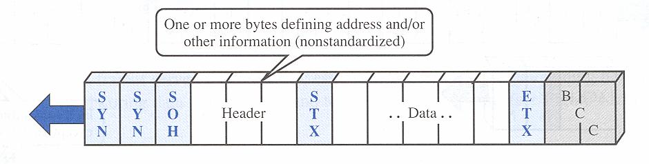
75 BSC data frame
76 Bit-Oriented Protocols in DLL Can pack more information into shorter frames are not grouped into predefined patterns forming characters Categories SDLC: synchronous data link protocol» developed in 1975 HDLC: high-level data link protocol» based on SDLC, developed in 1979 LAPs: Link Access Protocols» based on HDLC, developed in 1981» LAPB, LABD, LAPM, LAPX, etc LANs: LAN s access control protocol» Frame relay and PPP are developed by ITU-T and ANSI» based on HDLC
77 HDLC HDLC a basis for all bit-oriented protocols supports both half-duplex and full-duplex modes in point-to-point and multi-point configuration can be characterized by station types, configurations, and response modes Station types are of three types: primary, secondary, and combined primary: sends commands secondary: sends responses combined station: sends commands and responses Configurations refers to the relationship of hardware devices on a link primary or secondary between peers
78 HDLC Configurations

79 Communication Modes in HDLC The Relationship between two devices involved in an exchange describes who controls the link Three modes of communication NRM: Normal Response Mode the standard primary-secondary relationship a secondary device must have permission from the primary if granted the permission, then sends the responses ARM: Asynchronous Response Mode a secondary may initiate a transmission without primary s permission ABM: Asynchronous Balanced Mode
80 Frames in HDLC Three types of frames Information frames (I-frames) are used to transport user data and control information relating to user data Supervisory frames (S-frames) are used only to transport control information, primary data link layer flow and error controls Unnumbered frames (U-frames) are reserved for system management are intended for managing the link itself Six fields a beginning flag, an address, a control, an information, a frame check sequence (FCS), and an ending flag
81 HDLC frame types
82 HDLC control fields
83 Example of polling using HDLC
84 Example of selecting using HDLC
85 Example of peer-to-peer using HDLC
86 Link Access Procedures LAPB (Link access procedure, for balanced) a simplified subset of HDLC used only for connecting a station to a network provides the basic control functions required for communication between a DTE and A DCE is used only in balanced configurations of two devices» be used in ISDN on B channel LAPD (Link access procedure, for D channel) a simplified subset of HDLC used in ISDN uses ABM is used for out-of-band (control) signaling LAPM (Link access procedure, for Modem) a simplified subset of HDLC for modems» has been developed to apply HDLC features to modems is designed to do asynchronous-synchronous conversion, error detection, and transmission

87 CF: DTE-DCE Interface (1) DTE: Data Terminal Equipment any device that is a source of or destination for binary digital data DCE: Data Circuit-Terminating Equipment any device that transmits or receives data in the form of an analog or digital signal through a network
88 Example: Modems Stands for modulator/demodulator Modulator: Converts a digital signal to an analog signal Demodulator: Converts a analog signal to digital siganl
SRI RAMAKRISHNA INSTITUTE OF TECHNOLOGY DEPARTMENT OF INFORMATION TECHNOLOGY COMPUTER NETWORKS UNIT - II DATA LINK LAYER
 SRI RAMAKRISHNA INSTITUTE OF TECHNOLOGY DEPARTMENT OF INFORMATION TECHNOLOGY COMPUTER NETWORKS UNIT - II DATA LINK LAYER 1. What are the responsibilities of data link layer? Specific responsibilities of
Data Link Protocols DATA LINK PROTOCOLS. Asynchronous Protocols. Types of Data Link Protocols XMODEM. Asynchronous Protocols.
 Data Link Protocols DATA LINK PROTOCOLS Data Link Protocols are sets of rule and regulations used to implement data link layer. They contain rules for: Line Discipline Gursharan Singh Tatla mailme@gursharansingh.in
COMPUTER NETWORKS UNIT I. 1. What are the three criteria necessary for an effective and efficient networks?
 Question Bank COMPUTER NETWORKS Short answer type questions. UNIT I 1. What are the three criteria necessary for an effective and efficient networks? The most important criteria are performance, reliability
Data link layer functions. 2 Computer Networks Data Communications. Framing (1) Framing (2) Parity Checking (1) Error Detection
 Framing (2) Parity Checking (1) Error Detection") 2 Computer Networks Data Communications Part 6 Data Link Control Data link layer functions Framing Needed to synchronise TX and RX Account for all bits sent Error control Detect and correct errors Flow
2 Computer Networks Data Communications Part 6 Data Link Control Data link layer functions Framing Needed to synchronise TX and RX Account for all bits sent Error control Detect and correct errors Flow
Chapter 3. The Data Link Layer. Wesam A. Hatamleh
 Chapter 3 The Data Link Layer The Data Link Layer Data Link Layer Design Issues Error Detection and Correction Elementary Data Link Protocols Sliding Window Protocols Example Data Link Protocols The Data
William Stallings Data and Computer Communications. Chapter 7 Data Link Control
 William Stallings Data and Computer Communications Chapter 7 Data Link Control Flow Control Ensuring the sending entity does not overwhelm the receiving entity Preventing buffer overflow Transmission time
Data Link Networks. Hardware Building Blocks. Nodes & Links. CS565 Data Link Networks 1
 Data Link Networks Hardware Building Blocks Nodes & Links CS565 Data Link Networks 1 PROBLEM: Physically connecting Hosts 5 Issues 4 Technologies Encoding - encoding for physical medium Framing - delineation
Chapter 7: Data Link Control. CS420/520 Axel Krings Page 1
 Chapter 7: Data Link Control CS420/520 Axel Krings Page 1 Data Link Control Protocols Need layer of logic above Physical to manage exchange of data over a link frame synchronization flow control error
Chapter 7: Data Link Control. Data Link Control Protocols
 Chapter 7: Data Link Control CS420/520 Axel Krings Page 1 Data Link Control Protocols Need layer of logic above Physical to manage exchange of data over a link frame synchronization flow control error
DATA LINK LAYER UNIT 7.
 DATA LINK LAYER UNIT 7 1 Data Link Layer Design Issues: 1. Service provided to network layer. 2. Determining how the bits of the physical layer are grouped into frames (FRAMING). 3. Dealing with transmission
Direct Link Networks: Building Blocks (2.1), Encoding (2.2), Framing (2.3)
, Encoding (2.2), Framing (2.3)") Direct Link Networks: Building Blocks (2.1), Encoding (2.2), Framing (2.3) ECPE/CS 5516: Computer Networks Originally by Scott F. Midkiff (ECpE) Modified by Marc Abrams (CS) Virginia Tech courses.cs.vt.edu/~cs5516
Direct Link Networks: Building Blocks (2.1), Encoding (2.2), Framing (2.3) ECPE/CS 5516: Computer Networks Originally by Scott F. Midkiff (ECpE) Modified by Marc Abrams (CS) Virginia Tech courses.cs.vt.edu/~cs5516
PART III. Data Link Layer MGH T MGH C I 204
 PART III Data Link Layer Position of the data-link layer Data link layer duties LLC and MAC sublayers IEEE standards for LANs Chapters Chapter 10 Error Detection and Correction Chapter 11 Data Link Control
The data link layer has a number of specific functions it can carry out. These functions include. Figure 2-1. Relationship between packets and frames.
 Module 2 Data Link Layer: - Data link Layer design issues - Error Detection and correction Elementary Data link protocols, Sliding window protocols- Basic Concept, One Bit Sliding window protocol, Concept
Data Link Layer. Overview. Links. Shivkumar Kalyanaraman
 Data Link Layer shivkuma@ecse.rpi.edu http://www.ecse.rpi.edu/homepages/shivkuma 1-1 Based in part upon the slides of Prof. Raj Jain (OSU) Overview The data link layer problem Error detection and correction
Introduction to Computer Networks. 03 Data Link Layer Introduction
 Introduction to Computer Networks 03 Data Link Layer Introduction Link Layer 1 Introduction and services 2 Link Layer Services 2.1 Framing 2.2 Error detection and correction 2.3 Flow Control 2.4 Multiple
CSMC 417. Computer Networks Prof. Ashok K Agrawala Ashok Agrawala Set 4. September 09 CMSC417 Set 4 1
 CSMC 417 Computer Networks Prof. Ashok K Agrawala 2009 Ashok Agrawala Set 4 1 The Data Link Layer 2 Data Link Layer Design Issues Services Provided to the Network Layer Framing Error Control Flow Control
LECTURE #34. Data Communication (CS601)
") LECTURE #34 Error Detection And Correction Methods Longitudinal Red Check(LRC) o In LRC, a block of bits is organized in a table (rows and columns) o For example instead of sending 32 bits, we organize
LECTURE #34 Error Detection And Correction Methods Longitudinal Red Check(LRC) o In LRC, a block of bits is organized in a table (rows and columns) o For example instead of sending 32 bits, we organize
Chapter 3. The Data Link Layer
 Chapter 3 The Data Link Layer 1 Data Link Layer Algorithms for achieving reliable, efficient communication between two adjacent machines. Adjacent means two machines are physically connected by a communication
CS 4453 Computer Networks Winter
 CS 4453 Computer Networks Chapter 2 OSI Network Model 2015 Winter OSI model defines 7 layers Figure 1: OSI model Computer Networks R. Wei 2 The seven layers are as follows: Application Presentation Session
Lecture 2 Error Detection & Correction. Types of Errors Detection Correction
 Lecture 2 Error Detection & Correction Types of Errors Detection Correction Basic concepts Networks must be able to transfer data from one device to another with complete accuracy. Data can be corrupted
Data Link Control. Claude Rigault ENST Claude Rigault, ENST 11/3/2002. Data Link control 1
 Data Link Control Claude Rigault ENST claude.rigault@enst.fr Data Link control Data Link Control Outline General principles of Data Link Control HDLC Data Link control 2 General principles of Data Link
CSMC 417. Computer Networks Prof. Ashok K Agrawala Ashok Agrawala. Nov 1,
 CSMC 417 Computer Networks Prof. Ashok K Agrawala 2018 Ashok Agrawala 1 Message, Segment, Packet, and Frame host host HTTP HTTP message HTTP TCP TCP segment TCP router router IP IP packet IP IP packet
MYcsvtu Notes DATA REPRESENTATION. Data Types. Complements. Fixed Point Representations. Floating Point Representations. Other Binary Codes
 DATA REPRESENTATION Data Types Complements Fixed Point Representations Floating Point Representations Other Binary Codes Error Detection Codes Hamming Codes 1. DATA REPRESENTATION Information that a Computer
ECE 4450:427/527 - Computer Networks Spring 2017
 ECE 4450:427/527 - Computer Networks Spring 2017 Dr. Nghi Tran Department of Electrical & Computer Engineering Lecture 5.1: Link Layer Dr. Nghi Tran (ECE-University of Akron) ECE 4450:427/527 Computer
Advanced Computer Networks. Rab Nawaz Jadoon DCS. Assistant Professor COMSATS University, Lahore Pakistan. Department of Computer Science
 Advanced Computer Networks Rab Nawaz Jadoon Department of Computer Science DCS COMSATS Institute of Information Technology Assistant Professor COMSATS University, Lahore Pakistan Advanced Computer Networks
Flow control: Ensuring the source sending frames does not overflow the receiver
 Layer 2 Technologies Layer 2: final level of encapsulation of data before transmission over a physical link responsible for reliable transfer of frames between hosts, hop by hop, i.e. on a per link basis
(Refer Slide Time: 2:20)
") Data Communications Prof. A. Pal Department of Computer Science & Engineering Indian Institute of Technology, Kharagpur Lecture-15 Error Detection and Correction Hello viewers welcome to today s lecture
Data Communications Prof. A. Pal Department of Computer Science & Engineering Indian Institute of Technology, Kharagpur Lecture-15 Error Detection and Correction Hello viewers welcome to today s lecture
Data Link Control Protocols
 Data Link Control Protocols need layer of logic above Physical to manage exchange of data over a link frame synchronization flow control error control addressing control and data link management Flow Control
4. Error correction and link control. Contents
 //2 4. Error correction and link control Contents a. Types of errors b. Error detection and correction c. Flow control d. Error control //2 a. Types of errors Data can be corrupted during transmission.
Chapter Six. Errors, Error Detection, and Error Control. Data Communications and Computer Networks: A Business User s Approach Seventh Edition
 Chapter Six Errors, Error Detection, and Error Control Data Communications and Computer Networks: A Business User s Approach Seventh Edition After reading this chapter, you should be able to: Identify
 ET3110 Networking and Communications UNIT 2: Communication Techniques and Data Link Control Protocol skong@itt-tech.edutech.edu Learning Objectives Identify methods of detecting errors. Use Hamming code
DATA COMMUNICATIONS AND COMPUTER NETWORKS
 DATA COMMUNICATIONS AND COMPUTER NETWORKS Second Edition PRAKASH C. GUPTA Formerly Head Department of Information Technology Maharashtra Institute of Technology Pune Delhi-110092 2014 DATA COMMUNICATIONS
Computer Network. Direct Link Networks Reliable Transmission. rev /2/2004 1
 Computer Network Direct Link Networks Reliable Transmission rev 1.01 24/2/2004 1 Outline Direct link networks (Ch. 2) Encoding Framing Error detection Reliable delivery Media access control Network Adapter
MYcsvtu Notes UNIT II
 UNIT II Syllabus Introduction Perspective of network Protocols and standard Network Topologies Transmission Mode Categories of network LAN, MAN, WAN, OSI Model Functions of the layer TCP/IP Protocol suit
Department of Computer and IT Engineering University of Kurdistan. Data Communication Netwotks (Graduate level) Data Link Layer
 Data Link Layer") Department of Computer and IT Engineering University of Kurdistan Data Communication Netwotks (Graduate level) Data Link Layer By: Dr. Alireza Abdollahpouri Data Link Layer 2 Data Link Layer Application
Department of Computer and IT Engineering University of Kurdistan Data Communication Netwotks (Graduate level) Data Link Layer By: Dr. Alireza Abdollahpouri Data Link Layer 2 Data Link Layer Application
TYPES OF ERRORS. Data can be corrupted during transmission. Some applications require that errors be detected and corrected.
 Data can be corrupted during transmission. Some applications require that errors be detected and corrected. TYPES OF ERRORS There are two types of errors, 1. Single Bit Error The term single-bit error
CompSci 356: Computer Network Architectures. Lecture 4: Link layer: Encoding, Framing, and Error Detection Ref. Chap 2.2, 2.3,2.4
 CompSci 356: Computer Network Architectures Lecture 4: Link layer: Encoding, Framing, and Error Detection Ref. Chap 2.2, 2.3,2.4 Xiaowei Yang xwy@cs.duke.edu Overview Review: link/network performance metrics
Packet/Frame, Error Detection How to send data efficiently & reliably?
 Packet/Frame, Error Detection How to send data efficiently & reliably? Packet and Packet Communication - Shared Network Resource, Fairness, Reliability Frame - Byte Oriented Frame and Bit Oriented Frame
Lecture / The Data Link Layer: Framing and Error Detection
 Lecture 2 6.263/16.37 The Data Link Layer: Framing and Error Detection MIT, LIDS Slide 1 Data Link Layer (DLC) Responsible for reliable transmission of packets over a link Framing: Determine the start
3. Data Link Layer 3-2
 3. Data Link Layer 3.1 Transmission Errors 3.2 Error Detecting and Error Correcting Codes 3.3 Bit Stuffing 3.4 Acknowledgments and Sequence Numbers 3.5 Flow Control 3.6 Examples: HDLC, PPP 3. Data Link
(Sicherungsschicht) Chapter 5 (part 2) [Wa0001] HDLC - 1.
![(Sicherungsschicht) Chapter 5 (part 2) [Wa0001] HDLC - 1.](/thumbs/74/71111055.jpg "(Sicherungsschicht) Chapter 5 (part 2) [Wa0001] HDLC - 1.") Data Link Layer (cont.) (Sicherungsschicht) Chapter 5 (part 2) [Wa0001] HDLC - 1 LOGICAL LINK CONTROL MEDIUM ACCESS CONTROL PHYSICAL SIGNALING DATA LINK LAYER PHYSICAL LAYER ACCESS UNIT INTERFACE PHYSICAL
Data Link Layer (cont.) (Sicherungsschicht) Chapter 5 (part 2) [Wa0001] HDLC - 1 LOGICAL LINK CONTROL MEDIUM ACCESS CONTROL PHYSICAL SIGNALING DATA LINK LAYER PHYSICAL LAYER ACCESS UNIT INTERFACE PHYSICAL
Data Link Technology. Suguru Yamaguchi Nara Institute of Science and Technology Department of Information Science
 Data Link Technology Suguru Yamaguchi Nara Institute of Science and Technology Department of Information Science Agenda Functions of the data link layer Technologies concept and design error control flow
Data Link Layer. Learning Objectives. Position of the data-link layer. MCA 207, Data Communication & Networking
 Data Link Layer Bharati Vidyapeeth s Institute of Computer Applications and Management,New Delhi-63 by Vishal Jain U2. 1 Learning Objectives To introduce the design issues of data link layer. To discuss
Links. CS125 - mylinks 1 1/22/14
 Links 1 Goals of Today s Lecture Link-layer services Encoding, framing, and error detection Error correction and flow control Sharing a shared media Channel partitioning Taking turns Random access Shared
CS254 Network Technologies. Lecture 2: Network Models & Error Detection and Correction. Dr Nikos Antonopoulos
 CS254 Network Technologies Lecture 2: Network Models & Error Detection and Correction Dr Nikos Antonopoulos Department of Computing University of Surrey Autumn 2006 2.1 Layered Tasks Sender, Receiver,
Data Link Layer (cont.) ( h h h ) (Sicherungsschicht) HDLC - 1.
 ( h h h ) (Sicherungsschicht) HDLC - 1.") Data Link Layer (cont.) ( h h h ) (Sicherungsschicht) HDLC - 1 LOGICAL L LINK CONTROL MEDIUM ACCESS CONTROL PHYSICAL SIGNALING DATA LINK LAYER PHYSICAL LAYER ACCESS UNIT INTERFACE PHYSICAL MEDIA ATTACHMENT
Data Link Layer (cont.) ( h h h ) (Sicherungsschicht) HDLC - 1 LOGICAL L LINK CONTROL MEDIUM ACCESS CONTROL PHYSICAL SIGNALING DATA LINK LAYER PHYSICAL LAYER ACCESS UNIT INTERFACE PHYSICAL MEDIA ATTACHMENT
2.1 CHANNEL ALLOCATION 2.2 MULTIPLE ACCESS PROTOCOLS Collision Free Protocols 2.3 FDDI 2.4 DATA LINK LAYER DESIGN ISSUES 2.5 FRAMING & STUFFING
 UNIT-2 2.1 CHANNEL ALLOCATION 2.2 MULTIPLE ACCESS PROTOCOLS 2.2.1 Pure ALOHA 2.2.2 Slotted ALOHA 2.2.3 Carrier Sense Multiple Access 2.2.4 CSMA with Collision Detection 2.2.5 Collision Free Protocols 2.2.5.1
The Data Link Layer Chapter 3
 The Data Link Layer Chapter 3 Data Link Layer Design Issues Error Detection and Correction Elementary Data Link Protocols Sliding Window Protocols Example Data Link Protocols Revised: August 2011 & February
Data Link Layer Overview
 Data Link Layer Overview First of four classes on the data link layer Internet Architecture Bottom up: Physical: electromagnetic signals on the wire Link: data transfer between neighboring network elements
I. INTRODUCTION. each station (i.e., computer, telephone, etc.) directly connected to all other stations
 directly connected to all other stations") I. INTRODUCTION (a) Network Topologies (i) point-to-point communication each station (i.e., computer, telephone, etc.) directly connected to all other stations (ii) switched networks (1) circuit switched
I. INTRODUCTION (a) Network Topologies (i) point-to-point communication each station (i.e., computer, telephone, etc.) directly connected to all other stations (ii) switched networks (1) circuit switched
Telecom Systems Chae Y. Lee. Contents. Flow Control Error Detection/Correction Link Control (Error Control) Link Performance (Utility)
 Link Performance (Utility)") Data Link Control Contents Flow Control Error Detection/Correction Link Control (Error Control) Link Performance (Utility) 2 Flow Control Flow control is a technique for assuring that a transmitting entity
Data Link Control Contents Flow Control Error Detection/Correction Link Control (Error Control) Link Performance (Utility) 2 Flow Control Flow control is a technique for assuring that a transmitting entity
HDLC. Telecom Systems Chae Y. Lee
 HDLC Telecom Systems Contents Telecom Systems HDLC frame formats: Information/Supervisory/Non-sequenced Flow/Error Control in HDLC (Supervisory format) Link establish/disconnect (Non-sequenced format)
Data Link Layer Overview
 Data Link Layer Overview First of four classes on the data link layer Internet Architecture Bottom up: Physical: electromagnetic signals on the wire Link: data transfer between neighboring network elements
Positional Number System
 Positional Number System A number is represented by a string of digits where each digit position has an associated weight. The weight is based on the radix of the number system. Some common radices: Decimal.
DATA LINK LAYER: NEED
 Page no: 1 Department of Computer Science and Engineering CS6004 Computer Networking Subject Notes: UNIT-II DATA LINK LAYER: NEED Data Link Layer is second layer of OSI Layered Model. This layer is one
Inst: Chris Davison
 ICS 153 Introduction to Computer Networks Inst: Chris Davison cbdaviso@uci.edu ICS 153 Data Link Layer Contents Simplex and Duplex Communication Frame Creation Flow Control Error Control Performance of
Point-to-Point Links. Outline Encoding Framing Error Detection Sliding Window Algorithm. Fall 2004 CS 691 1
 Point-to-Point Links Outline Encoding Framing Error Detection Sliding Window Algorithm Fall 2004 CS 691 1 Encoding Signals propagate over a physical medium modulate electromagnetic waves e.g., vary voltage
Data Link Layer Overview
 Data Link Layer Overview : 9/7/2007 CSC 257/457 - Fall 2007 1 Internet Architecture Bottom-up: physical: electromagnetic signals on the wire link: data transfer between neighboring network elements network:
COMPUTER NETWORKS UNIT-3
 COMPUTER NETWORKS UNIT-3 Syllabus: The Data Link Layer - Data Link Layer Design Issues, Services Provided to the Network Layer Framing Error Control Flow Control, Error Detection and Correction Error-Correcting
Chapter 5 Data-Link Layer: Wired Networks
 Sungkyunkwan University Chapter 5 Data-Link Layer: Wired Networks Prepared by Syed M. Raza and H. Choo 2018-Fall Computer Networks Copyright 2000-2018 Networking Laboratory Chapter 5 Outline 5.1 Introduction
Data Link Layer Overview
 Data Link Layer Overview First of four classes on the data link layer 9/9/2009 CSC 257/457 - Fall 2009 1 Internet Architecture Bottom-up: physical: electromagnetic signals on the wire link: data transfer
Configuration of Synchronous Protocols
 encor! enetworks TM Version A, September 2010 2013 Encore Networks, Inc. All rights reserved. Configuration of Synchronous Protocols This chapter discusses synchronous protocols that you can configure
Advanced Computer Networks. Rab Nawaz Jadoon DCS. Assistant Professor COMSATS University, Lahore Pakistan. Department of Computer Science
 Advanced Computer Networks Department of Computer Science DCS COMSATS Institute of Information Technology Rab Nawaz Jadoon Assistant Professor COMSATS University, Lahore Pakistan Advanced Computer Networks
CSCI-1680 Link Layer I Rodrigo Fonseca
 CSCI-1680 Link Layer I Rodrigo Fonseca Based partly on lecture notes by David Mazières, Phil Levis, John Jannotti Last time Physical layer: encoding, modulation Today Link layer framing Getting frames
Chapter 9: Data Transmission
 Chapter 9: Data Transmission MULTIPLE CHOICE 1. In practical terms, parallel data transmission is sent: a. over short distances only c. over any distance b. usually over long distances d. usually over
Chapter 8 OSI Physical Layer
 Chapter 8 OSI Physical Layer Upper OSI layer protocols prepare data from the human network for transmission to its destination. The Physical layer controls how data is placed on the communication media.
QUESTION BANK EVEN SEMESTER
 Fatima Michael College of Engineering and Technology DEPARTMENT OF ELECTRONICS AND COMMUNICATION ENGINEERING QUESTION BANK EVEN SEMESTER SUB CODE & NAME: EC2352 COMPUTER NETWORKS YEAR / SEM: III / VI Staff
From Signals to Packets Computer Networking. Link Layer: Implementation. Datalink Functions. Lecture 5 - Coding and Error Control
 From Signals to Packets 15-441 Computer Networking Lecture 5 - Coding and Error Control Analog Signal Digital Signal Bit Stream 0 0 1 0 1 1 1 0 0 0 1 Packets 0100010101011100101010101011101110000001111010101110101010101101011010111001
I/O Organization John D. Carpinelli, All Rights Reserved 1
 I/O Organization 1997 John D. Carpinelli, All Rights Reserved 1 Outline I/O interfacing Asynchronous data transfer Interrupt driven I/O DMA transfers I/O processors Serial communications 1997 John D. Carpinelli,
Data Link Layer: Overview, operations
 Data Link Layer: Overview, operations Chapter 3 1 Outlines 1. Data Link Layer Functions. Data Link Services 3. Framing 4. Error Detection/Correction. Flow Control 6. Medium Access 1 1. Data Link Layer
HDLC (High level Data Link Control)
") High-level Data Link Control HDLC (High level Data Link Control) Modem, EIA-232, HDLC Framing and Procedures Agenda Line Management, Modems Introduction HDLC Station Types, Modes of Operation Frame Format,
High-level Data Link Control HDLC (High level Data Link Control) Modem, EIA-232, HDLC Framing and Procedures Agenda Line Management, Modems Introduction HDLC Station Types, Modes of Operation Frame Format,
Line Protocol Basics. HDLC (High level Data Link Control) Agenda. Additional Issues
 Agenda. Additional Issues") Line Protocol Basics High-level Data Link Control HDLC (High level Data Link Control), EIA-232, HDLC Framing and Procedures line protocol basics already explained serial transmission techniques bit-synchronization
Line Protocol Basics High-level Data Link Control HDLC (High level Data Link Control), EIA-232, HDLC Framing and Procedures line protocol basics already explained serial transmission techniques bit-synchronization
HDLC. King of the Link 2005/03/11. (C) Herbert Haas
 Herbert Haas") HDLC King of the Link (C) Herbert Haas 2005/03/11 What is HDLC? High-Level Data Link Control Early link layer protocol Based on SDLC (Synchronous-DLC, IBM) Access control on half-duplex modem-lines Connectionoriented
HDLC King of the Link (C) Herbert Haas 2005/03/11 What is HDLC? High-Level Data Link Control Early link layer protocol Based on SDLC (Synchronous-DLC, IBM) Access control on half-duplex modem-lines Connectionoriented
Data Link Layer. Srinidhi Varadarajan
 Data Link Layer Srinidhi Varadarajan Data Link Layer: Functionality The data link layer must: Detect errors (using redundancy bits) Request retransmission if data is lost (using automatic repeat request
Chapter 6 Digital Data Communications Techniques
 Chapter 6 Digital Data Communications Techniques Asynchronous and Synchronous Transmission timing problems require a mechanism to synchronize the transmitter and receiver receiver samples stream at bit
CS422 Computer Networks
 CS422 Computer Networks Lecture 3 Data Link Layer Dr. Xiaobo Zhou Department of Computer Science CS422 DataLinkLayer.1 Data Link Layer Design Issues Services Provided to the Network Layer Provide service
5th Slide Set Computer Networks
 Prof. Dr. Christian Baun 5th Slide Set Computer Networks Frankfurt University of Applied Sciences WS1718 1/38 5th Slide Set Computer Networks Prof. Dr. Christian Baun Frankfurt University of Applied Sciences
Direct Link Networks. Framing. Lecture - Encoding & Framing 1. Problems. Areas for Discussion
 Areas for Discussion Direct Link s Joseph Spring School of Computer Science 3COM0271 Computer Protocols & Architecture s Based on Chapter 2, Peterson & Davie, Computer s: A Systems Approach, 4 th Ed Problems
Lecture 5: Data Link Layer Basics
 Lecture 5: Data Link Layer Basics Dr. Mohammed Hawa Electrical Engineering Department University of Jordan EE426: Communication Networks Layer 2 PDU: Frame 2 1 Bit-oriented vs. Byte-oriented Layer 2 protocols
UNIT-II 1. Discuss the issues in the data link layer. Answer:
 UNIT-II 1. Discuss the issues in the data link layer. Answer: Data Link Layer Design Issues: The data link layer has a number of specific functions it can carry out. These functions include 1. Providing
Input-Output Organization
 Ted Borys - CSI 404 5/1/2004 Page 11-1 Section 11 Input-Output Organization ASCII Character Set 94 printable characters Upper & lowercase letters 10 numerals Special characters such as $, @, #, % 34 control
Achieving Reliable Digital Data Communication through Mathematical Algebraic Coding Techniques
 International Journal of Pure and Applied Mathematical Sciences. ISSN 0972-9828 Volume 9, Number 2 (2016), pp. 183-190 Research India Publications http://www.ripublication.com Achieving Reliable Digital
Chapter 10 Error Detection and Correction. Copyright The McGraw-Hill Companies, Inc. Permission required for reproduction or display.
 Chapter 10 Error Detection and Correction 0. Copyright The McGraw-Hill Companies, Inc. Permission required for reproduction or display. Note The Hamming distance between two words is the number of differences
Computer Networking. Lecture 4 - Coding and Error Control
 15-441 Computer Networking Lecture 4 - Coding and Error Control From Signals to Frames Analog Signal Digital Signal Bit Stream 0 0 1 0 1 1 1 0 0 0 1 Packets 0100010101011100101010101011101110000001111010101110101010101101011010111001
Telecommunications II TEL 202 Spring, 2004
 Telecommunications II TEL 202 Spring, 2004 Time: Lecture: Thursday 12:20 3:30 Lynn Campus, Room LW207 Laboratory: Thursday 4:00 5:00 Lynn Campus, Room LE201 Instructor: Scott Stimpson Office: Lynn, W228
KINGS COLLEGE OF ENGINEERING DEPARTMENT OF ELECTRONICS AND COMMUNICATION ENGINEERING B.E. ECE UNIT I DATA COMMUNICATION PART A
 KINGS CS1302 / COMPUTER NETWORKS COLLEGE OF ENGINEERING DEPARTMENT OF ELECTRONICS AND COMMUNICATION ENGINEERING B.E. ECE SUB.CODE : CS1302 BRANCH / YEAR / SEM: ECE / III / VI SUB.NAME : COMPUTER NETWORKS
Ch. 7 Error Detection and Correction
 Ch. 7 Error Detection and Correction Error Detection and Correction Data can be corrupted during transmission. Some applications require that errors be detected and corrected. 2 1. Introduction Let us
CS 455/555 Intro to Networks and Communications. Link Layer
 CS 455/555 Intro to Networks and Communications Link Layer Dr. Michele Weigle Department of Computer Science Old Dominion University mweigle@cs.odu.edu http://www.cs.odu.edu/~mweigle/cs455-s13 1 Link Layer
CSE 123A Computer Networks
 CSE 123A Computer Networks Winter 2005 Lecture 4: Data-Link I: Framing and Errors Some portions courtesy Robin Kravets and Steve Lumetta Last time How protocols are organized & why Network layer Data-link
UNIT I FUNDAMENTALS & LINK LAYER
 UNIT I FUNDAMENTALS & LINK LAYER Building a network Requirements - Layering and protocols - Internet Architecture Network software Performance ; Link layer Services - Framing - Error Detection Flow control.
Other Data Link Protocols: Computer Networks by Prof Kamal K Mehta Associate Professor Dept of Computer Science & Engineering
 Other Data Link Protocols: Data Link Protocol ategories A protocol in data communications is the set of rules or specifications used to implement partially a layer or one or more layers of the OSI model.
Direct Link Networks. Lecture - Encoding & Framing 1. Areas for Discussion. Problems
 Areas for Discussion Direct Link s Joseph Spring School of Computer Science 3COM0088 Computer Protocols & Architecture s Based on Chapter 2, Peterson & Davie, Computer s: A Systems Approach, 3 rd Ed Problems
INTERNET ARCHITECTURE & PROTOCOLS
 INTERNET ARCHITECTURE & PROTOCOLS Set # 02 Delivered By: Engr Tahir Niazi Need for Data Link Layer possibility of transmission errors receiver need to regulate the rate at which data arrive that's why
The Data Link Layer Chapter 3
 The Data Link Layer Chapter 3 Data Link Layer Design Issues Error Detection and Correction Elementary Data Link Protocols Sliding Window Protocols Example Data Link Protocols Revised: August 2011 The Data
CS1302-COMPUTER NETWORKS UNIT I -DATA COMMUNICATION PART A
 SHRI ANGALAMMAN COLLEGE OF ENGINEERING & TECHNOLOGY (An ISO 9001:2008 Certified Institution) SIRUGANOOR,TRICHY-621105. DEPARTMENT OF COMPUTER SCIENCE AND ENGINEERING CS1302-COMPUTER NETWORKS Year/Sem:
Overview. Data Link Technology. Role of the data-link layer. Role of the data-link layer. Function of the physical layer
 Overview Data Link Technology Functions of the data link layer Technologies concept and design error control flow control fundamental protocols Suguru Yamaguchi Nara Institute of Science and Technology
Computer and Network Security
 CIS 551 / TCOM 401 Computer and Network Security Spring 2009 Lecture 6 Announcements First project: Due: 6 Feb. 2009 at 11:59 p.m. http://www.cis.upenn.edu/~cis551/project1.html Plan for Today: Networks:
Introduction to Data Communications & Networking
 Introduction to Data Communications & Networking Data Link Layer (Set 5) Chapter 10 and Chapter 11 Dr. Ali Maqousi, Dr. Tatiana Balikhina amaqousi@uop.edu.jo, tbalikhina@uop.edu.jo Department of Computer
16.682: Communication Systems Engineering. Lecture 17. ARQ Protocols
 16.682: Communication Systems Engineering Lecture 17 ARQ Protocols Eytan Modiano Automatic repeat request (ARQ) Break large files into packets FILE PKT H PKT H PKT H Check received packets for errors Use
Data Link Control. Surasak Sanguanpong Last updated: 11 July 2000
 1/14 Data Link Control Surasak Sanguanpong nguan@ku.ac.th http://www.cpe.ku.ac.th/~nguan Last updated: 11 July 2000 Flow Control 2/14 technique for controlling the data transmission so that s have sufficient