GW-7472 / GW EtherNet/IP to Modbus RTU/TCP Gateway User Manual
|
|
|
- Damon Bishop
- 5 years ago
- Views:
Transcription

1 GW-7472 / GW-7473 EtherNet/IP to Modbus RTU/TCP Gateway User Manual Warranty All products manufactured by ICP DAS are under warranty regarding defective materials for a period of one year, starting from the date of delivery to the original purchaser. Warning ICP DAS assumes no liability for damages resulting from the use of this product. ICP DAS reserves the right to change this manual at any time without notice. The information published by ICP DAS is believed to be accurate and reliable. However, no responsibility is assumed by ICP DAS for its use, not for any infringements of patents or other rights of third parties resulting from its use. Copyright Copyright 2014 by ICP DAS Co., Ltd. All rights are reserved. Trademark The names used for identification only may be registered trademarks of their respective companies. GW-7472 / GW-7473 User Manual, Version 2.7, Dec
2 Table of Contents Packing List... 5 More Information Introduction Specifications Features Front View Dimensions Pin Assignment Wiring Note RS-422 Wire Connections RS-485 Wire Connections Setup and Test the Gateway Module Install the Utility Setting up the GW-7472 module Setting up the GW-7473 module GW-7472 Utility Functionalities Network Scan Module Configuration Network Settings Modbus RTU Serial Port Settings Modbus TCP Server IP Setting Setting File Management Byte Order Setting Modbus Request Settings Electronic Data Sheet Module Diagnostic UCMM/Forward Open Class 3 Behavior Forward Open Class 1 Behavior Modbus TCP Server Status Firmware Update GW-7473 Utility Functionalities GW-7472 / GW-7473 User Manual, Version 2.7, Dec
3 5.1 Communication interface GW-7473 Configurations Ethernet and Modbus RTU EtherNet/IP Adapter Modbus Command GW-7473 Address Mapping Vendor Defined Function Codes Function Code 100(0x64): Write IP Address Function Code 102(0x65): Read IP Address Function Code 103(0x66): Write Adapter information Function Code 104(0x67): Read Adapter information Firmware Update R/W Modbus devices from EtherNet/IP Object Model Explicit Message Implicit Message UCMM Assembly Object Supported Modbus Communication Appendix A: EtherNet/IP Object Model Device Object Model Identity Object (01 hex ) Message Router Object (02 hex ) Assembly Object (04 hex ) Connection Manager Object (06 hex ) TCP/IP Interface Object (F5 hex ) Ethernet Link Object (F6 hex ) CIP General Status Code Connection Manager Service Request Error Codes Appendix B: Glossary ARP (Address Resolution Protocol) Clients and Servers Ethernet Firmware Gateway ICMP (Internet Control Messages Protocol) GW-7472 / GW-7473 User Manual, Version 2.7, Dec
4 7. Internet IP (Internet Protocol) address MAC (Media Access Control) address Packet Ping RARP (Reverse Address Resolution Protocol) Socket Subnet Mask TCP (Transmission Control Protocol) TCP/IP UDP (User Datagram Protocol) Appendix C: FAQ GW-7472 / GW-7473 User Manual, Version 2.7, Dec


5 Packing List The shipping package includes the following items: One GW-7472/GW-7473 hardware module One printed Quick Start Guide One software utility CD Quick start Note!! If any of these items is missed or damaged, contact the local distributor for more information. Save the shipping materials and cartons in case you want to ship in the future. More Information Documentations Fieldbus_CD:\EtherNetIP\Gateway\GW-7472\Document Fieldbus_CD:\EtherNetIP\Gateway\GW-7473\Document Firmware Fieldbus_CD:\EtherNetIP\Gateway\GW-7472\Firmware Fieldbus_CD:\EtherNetIP\Gateway\GW-7473\Firmware Utility Fieldbus_CD:\EtherNetIP\Gateway\GW-7472\Utility Fieldbus_CD:\EtherNetIP\Gateway\GW-7473\Utility GW-7472 / GW-7473 User Manual, Version 2.7, Dec
6 1. Introduction GW-7472 The GW-7472 (EtherNet/IP adapter to Modbus RTU and Modbus TCP Master Gateway) is helpful for data-exchanging between the Modbus RTU along with Modbus TCP network and the EtherNet/IP network. The words Modbus described later are referring to Modbus RTU and Modbus TCP both, the words Modbus slave are also referring to Modbus RTU slave and Modbus TCP server both if there is not extra explanation. It reads the register data from the Modbus RTU/TCP slaves (server) and publishes these data to the input register data of the EtherNet/IP scanner. The output data transmitted by the EtherNet/IP scanner are updated to the register data of Modbus slaves via the GW Through the GW-7472, all of the Modbus slaves can be regard as one EtherNet/IP adapter. The GW-7472 allows maximum 6 connections for the Explicit Messages and 1 connection for the Implicit Messages at the same time. It means that 7 EtherNet/IP scanners can connect to one GW-7472 at the same time. Otherwise, the GW-7472 also allows maximum 10 Modbus TCP servers to communicate with it. The Modbus master functions of the GW-7472 can scan up to 30 Modbus RTU commands and 80 Modbus TCP commands (8 for each Modbus TCP slave). After configuring the Modbus master behavior of the GW-7472 and the mapping status between the Modbus registers and EtherNet/IP registers by using the GW-7472 Utility tool, the input/output registers of the Modbus slaves are mapping to the output/input registers of the EtherNet/IP adapter. While booting up, the GW-7472 scans the pre-defined register addresses in all of the Modbus slaves according to the sequence defined in the utility tool. The input and output register data of the Modbus devices are updated as soon as the GW-7472 could. In order to save the installation space, the GW-7472 is offered in an amazing tiny formfactor that makes it easy to install in anywhere, even directly attached to a serial device or embedded into a machine. The GW-7472 features a powerful 32-bit MCU to handle efficient network traffic and it provides the IEEE 802.3af-compliant (classification, Class 1) Power over Ethernet (PoE) with a standard category 5 Ethernet cable. Through the NS-205PSE, Poe switch, the GW-7472 can be powered via the Ethernet cable. When there is no PoE switch on site, the GW-7472 provide another way to be powered from DC adapters. These two power interfaces are redundant. If one fails, another will take it over to supply the proper power to the GW GW-7472 / GW-7473 User Manual, Version 2.7, Dec
 provided by the GW-7472.")
7 The following figure briefs the concept of the data exchange between the EtherNet/IP and the Modbus network. In this system, there are two Modbus RTU slaves along with two Modbus TCP servers connected to the Modbus master(client) provided by the GW The EtherNet/IP adapter interface of the GW-7472 is connected to an EtherNet/IP scanner through an Ethernet switch. Register data of the three Modbus slaves is presented to the EtherNet/IP scanner as the I/O data. Figure 1.1 GW-7472 applications The following figure illustrates how to deploy the register data of the Modbus devices in the previous example to the EtherNet/IP scanner. Assume that there are 3, 2, 2, and 4 input registers data in the Modbus slaves No.1, No.2, No.3 and No.4 respectively. The data format of the register in the Modbus slave No.1, and No.3 is WORD, and that in the Modbus slave No.2, and No.4 is BYTE. All of these input registers are mapping to the corresponding input registers of the EtherNet/IP adapter of the GW-7472 sequentially by using the BYTE format. The output register data of the Modbus slaves are mapping in exactly the same way. The Modbus slave output registers are mapping as the output registers of the EtherNet/IP adapter of the GW Users can set the maximum 500 bytes for input data and 500 bytes for output data which are mapping to the EtherNet/IP adapter of the GW All of these configurations are defined by using the GW-7472 Utility tool. While the GW-7472 gets the EtherNet/IP GW-7472 / GW-7473 User Manual, Version 2.7, Dec

8 commands from the EtherNet/IP scanner, it collects the input register data from Modbus slaves and updates the output register data to the Modbus slaves as soon as possible. We have confirmed that GW-7472 can operate normally with Allen-Bradley ControlLogix Logix 5563 through 1756-ENBT ControlLogix EtherNet/IP Module setup by RSLogix 5000 software. GW-7473 Figure 1.2 GW-7472 data-exchange The GW-7473 (Modbus TCP/RTU Slave to EtherNet/IP Scanner Gateway) is helpful for data-exchanging between Modbus Master and EtherNet/IP adapter. It reads the register data from the EtherNet/IP adapter and publishes these data to the input register data of the Modbus TCP client as well as Modbus RTU Master. The output data transmitted by the Modbus TCP/RTU Master are updated to the register data of EtherNet/IP adapter. We provide 200 bytes data buffer for I/O data. GW-7473 can save all the I/O data which is received or sent by EtherNet/IP in their own buffer. For example, GW-7473 receives one or GW-7472 / GW-7473 User Manual, Version 2.7, Dec

9 more EtherNet/IP adapter packets. The GW-7473 can import input status(di, AI,, etc) from EtherNet/IP adapter packets, and save them into input buffer(di buffer, AI buffer,, etc). We provide 200 bytes for every input or output buffer. In order to save the installation space, the GW-7473 is also offered in an amazing tiny form-factor that makes it easy to install in anywhere, even directly attached to a serial device or embedded into a machine. The GW-7473 features a powerful 32-bit MCU to handle efficient network traffic and it provides the IEEE 802.3af-compliant (classification, Class 1) Power over Ethernet (PoE) with a standard category 5 Ethernet cable. Through the NS-205PSE, Poe switch, the GW-7473 can be powered via the Ethernet cable. When there is no PoE switch on site, the GW-7473 provide another way to be powered from DC adapters. These two power interfaces are redundant. If one fails, another will take it over to supply the proper power to the GW Figure 1.3 GW-7473 data-exchange GW-7472 / GW-7473 User Manual, Version 2.7, Dec
10 2. Hardware Information 2.1 Specifications Model System CPU Table 2.1 GW-7472 / GW7473 specifications GW-7472 / GW bit MCU Communication Interface 10/100 Base-TX, 8-pin RJ-45 x 1, Ethernet (Auto-negotiating, Auto-MDI/MDIX, LED indicator) PoE (IEEE 802.3af, Class 1) COM1 2-wire RS-485 / 4-wire RS-422 Self-Tuner Yes, automatic RS-485 direction control UART COM Port Format 16c550 or compatible Baud Rate 1200 to bps. Data Bit 7, 8 Parity Stop Bit 1, 2 General Power Input Power Consumption None, Odd, Even PoE: IEEE 802.3af, Class 1 DC jack: +12 ~ 48 V DC VDC Connector 10-Pin Removable Terminal Block x 1 Mounting DIN-Rail Operating Temperature -25 ~ 75 C Storage Temperature -30 ~ 80 C Humidity 10 ~ 90% RH, non-condensing GW-7472 / GW-7473 User Manual, Version 2.7, Dec
11 2.2 Features GW-7472 General Features: Powerful 32-bit MCU handles efficient network traffic 10/100 Base-TX Ethernet, RJ-45 x1 (Auto-negotiating, auto MDI/MDIX, LED Indicators) Redundant power inputs: PoE (IEEE 802.3af, Class 1) and DC jack Automatically RS-485 direction control Support ARP,TCP, UDP, ICMP, DHCP, BOOTP and TFTP protocols Easy firmware update via Ethernet Removable terminal block connector Tiny form-factor and low power consumption RoHS compliant with Halogen-free EtherNet/IP Features: Ethernet Protocol: EtherNet/IP adapter Maximum number of connections for Explicit Messages: 6 Maximum number of connections for Implicit Messages: 1 Supported I/O connection methods: Transport and trigger: Exclusive-Owner, Cyclic Originator to Target Type: POINT2POINT Target to Originator Type: POINT2POINT, MULTICAST Device Configuration Option: EDS, Utility tool Address Configuration: DHCP, Utility tool EtherNet/IP Input / Output command data size: maximum 500 bytes The numbers of the Modbus slave input registers mapping to the input registers of the EtherNet/IP adapter of the GW-7472: maximum 500 bytes The numbers of the Modbus slave output registers mapping to the output registers of the EtherNet/IP adapter of the GW-7472: maximum 500 bytes GW-7472 / GW-7473 User Manual, Version 2.7, Dec
12 Modbus Features: Modbus Protocol: Modbus RTU Master and Modbus TCP Client Maximum support 30 Modbus RTU commands Maximum support 10 Modbus TCP servers Maximum support 8 Modbus RTU commands for each one Modbus TCP server Supported Modbus Function Codes: 01 hex: Read Output Status 02 hex: Read Input Status 03 hex: Read Multiple Data Registers 04 hex: Read Input Registers 05 hex: Write Single Coil 06 hex : Write Single Register 0F hex: Write Multiple Bits 10 hex : Write Multiple Data Register Maximum data size of one Modbus command: 240 bytes GW-7473 General Features: Powerful 32-bit MCU handles efficient network traffic 10/100 Base-TX Ethernet, RJ-45 x1 Redundant power inputs: PoE (IEEE 802.3af, Class 1) and DC jack Support ARP,TCP, UDP, ICMP, DHCP, BOOTP and TFTP protocols Easy firmware update via Ethernet Removable terminal block connector Tiny form-factor and low power consumption RoHS compliant with Halogen-free EtherNet/IP Features: Supported Objects according to CIP Standard Assembly Object Connection Manager Object Ethernet Link Object Message Router Object TCP/IP Interface Object Ethernet Protocol: EtherNet/IP Scanner Class 1 (connected) I/O Server and Client Class 3 (connected) Message Server and Client Maximum support 5 EtherNet/IP adapter connections GW-7472 / GW-7473 User Manual, Version 2.7, Dec
13 EtherNet/IP I/O command data size: 200 bytes Modbus Features: Modbus Protocol: Modbus TCP Server/RTU Slave protocols Maximum support 5 Modbus TCP clients Supported Modbus RTU Function Codes: 01 hex: Read Output Status 02 hex: Read Input Status 03 hex: Read Multiple Data Registers 04 hex: Read Input Registers 0F hex: Write Multiple Bits 10 hex: Write Multiple Data Register GW-7472 / GW-7473 User Manual, Version 2.7, Dec

 indicator will be turned on.")
14 2.3 Front View Serial COM Ports Robust insulated and fire retardant case S1: System LED indicator Operating Mode Selector PoE and Ethernet RJ-45 Jack +12~+48 VDC Jack 1. PoE and Ethernet RJ-45 Jack: GW-7472/GW-7473 is equipped with a RJ-45 jack for the 10/100 Base-TX Ethernet port and features networking capability. When the Ethernet link is detected and Ethernet packet is received, the Link/Act LED (Orange) indicator will be turned on. When the power is supplied via PoE (Power-over-Ethernet), the PoE LED (Green) indicator will be turned on. GW-7472 / GW-7473 User Manual, Version 2.7, Dec


15 2. +12~+48 VDC Jack: The GW-7472 / GW-7473 is equipped with a +12~+48 VDC jack for the power supply. When there is no PoE switch on site, the GW-7472/ GW-7473 accepts the power from the DC adapter. Please refer to the following web site for more details S1: System LED indicator: GW-7472 After power on the GW-7472, the system LED indicator is as follows: Table 2.2 GW-7472 LED indicator Function System LED Action Running Firmware Flashing per second Hardware checking error Flashing per 0.3 seconds Hardware error Off GW-7473 After power on the GW-7473, the system LED indicator is as follows: Table 2.3 GW-7473 LED indicator Function System LED Action Running Firmware On Connect to EIP Adapter Flashing per seconds Hardware error Off 4. Operating Mode Selector: Init Mode: Configuration mode Run Mode: Firmware running mode Generally, the switch is always in the Run position while the gateway works. Only when GW-7472 / GW-7473 User Manual, Version 2.7, Dec
16 updating the gateway, the switch needs to be set to the Init position. Move the switch to the Run position and then re-power on the gateway after the update is completed. Mode Firmware Running Flash Protection Firmware Update Configuration Init No No Yes Allowed Run Yes Yes No Allowed 2.4 Dimensions Unit: mm Front View Back View Top View Left Side View Right Side View Bottom View GW-7472 / GW-7473 User Manual, Version 2.7, Dec

17 2.5 Pin Assignment 1-Port 2-Wire RS-485/ 4-Wire RS-422 Module GW-7472 / GW-7473 User Manual, Version 2.7, Dec

18 2.6 Wiring Note RS-422 Wire Connections RS-485 Wire Connections Note!! For non-isolated RS-422/485 ports, you should connect all signal grounds of RS-422/485 devices together. This reduces common-mode voltage between devices. GW-7472 / GW-7473 User Manual, Version 2.7, Dec


19 3. Setup and Test the Gateway Module 3.1 Install the Utility Step 1: Get the GW-7472 / GW-7473 Utility The software is located at: Fieldbus_CD:\EtherNetIP\Gateway\GW-7472\Utility Fieldbus_CD:\EtherNetIP\Gateway\GW-7473\Utility Step 2: Install.NET Framework 4 component The Utility tool requires the Windows Installer 3.1 and the.net Framework 4 components. These components can be obtained from the web site. GW-7472 / GW-7473 User Manual, Version 2.7, Dec


20 Step 3: Install Utility tool After installing the.net Framework components, please run the Utility setup file. 1. Click the Next button to continue. 2. Select the installation path of the Utility and click the Next button. GW-7472 / GW-7473 User Manual, Version 2.7, Dec

21 3. Confirm the installation. Click the Next button to start the installation 4. Installation complete. Click the Close button to exit GW-7472 / GW-7473 User Manual, Version 2.7, Dec
22 3.2 Setting up the GW-7472 module Step 1: Connect the power and host PC 1. Make sure your PC is under the workable network configuration and environment. 2. First, disable or correctly configure the firewall of the Windows system and any antivirus software. Or, the Configure function of the GW-7472 Utility may not work. (Contact your system administrator for more details about how to do this.) 3. Check Init/Run switch is on Init position. 4. In Init mode, the GW-7472 is forced to the network configuration as following table. Connect the GW-7472 with your computer at the same sub network or by using the same Ethernet switch. Then power the GW-7472 on. Afterwards, you can use the command ping in the Command Prompt window to test if the connection between the GW-7472 and your computer is OK. Item Settings (Init Mode) IP Gateway Mask GW-7472 / GW-7473 User Manual, Version 2.7, Dec
23 5. Make sure the System LED indicator is flashing. Figure 3.1 GW-7472 with DC jack power supply Figure 3.2 GW-7472 with PoE switch power supply GW-7472 / GW-7473 User Manual, Version 2.7, Dec
24 Step 2: Search and configure the GW Double click the GW-7472 Utility shortcut on the desktop. 2. Click the Network Scan button to search your GW Select the item of the GW-7472 and click the Configure button to open the configuration dialog. 4. After setting all the parameter of the GW-7472, click the Update Settings button to save the configuration. After click the Update Settings button, the GW-7472 will reboot to complete the configuration. Figure 3.3 GW-7472 Utiity Please refer to the section 4.2 Module Configuration for details GW-7472 / GW-7473 User Manual, Version 2.7, Dec


25 3.3 Setting up the GW-7473 module Step 1: Connect the power and host PC 1. Make sure your PC has workable network settings. 2. Disable or well configure your Windows firewall and anti-virus firewall first. 3. Check Init/Run DIP switch if it is on Run position. 4. You can make Modbus RTU connections between PC and GW-7473 with RS-485/RS- 422 converter 5. Connect both the GW-7473 and your computer to the same sub network or the same Ethernet switch, and power the GW-7473 on. GW-7473 also supports to PoE connections. Users can make a PoE connection with a PoE switch. Figure 3.4 GW-7473 with DC jack power supply GW-7472 / GW-7473 User Manual, Version 2.7, Dec

26 Figure 3.5 GW-7473 with PoE switch power supply Step 2: GW-7473 Utility 6. Double click the GW-7473 Utility shortcut on the desktop. 7. Select the connection interface Modbus RTU or Modbus TCP. 8. Click connect to open Configuration Window. Figure 3.6 GW-7473 Utility GW-7472 / GW-7473 User Manual, Version 2.7, Dec

27 4. GW-7472 Utility Functionalities 4.1 Network Scan 1. Double click the GW-7472 Utility shortcut on the desktop. 2. Click the Network Scan button to search your GW Afterwards, you can see all of the GW-7472 on the same network of your PC. GW-7472 / GW-7473 User Manual, Version 2.7, Dec
28 4.2 Module Configuration 1. Double click the GW-7472 Utility shortcut on the desktop. 2. Click the Network Scan button to search your GW Select the item of the GW-7472 and click the Configure button to open the Configuration dialog. 4. After setting all the parameter of the GW-7472, click the Update Settings button to save the configuration. After click the Update Settings button, the GW-7472 will reboot to complete the configuration. GW-7472 / GW-7473 User Manual, Version 2.7, Dec
29 Item Descriptions: Item Table 4.1 GW-7472 setting parameters Description Network Settings Modbus RTU Port Settings Modbus TCP Server IP Setting Setting File Management Byte Order Setting Modbus Request Command Setting For configuration of the Address Type, Static IP Address, Subnet Mask and Default Gateway of the GW-7472 Please refer to section Network Settings For configuration of the Baud Rate, Data Sizes, Parity, Stop Bits, of the RS-485/RS-422 port of the GW-7472 Please refer to section Modbus RTU Serial Port Settings For configuration of the IP of each Modbus TCP server. Please refer to section Modbus TCP Server IP Settings For the setting files management of GW Please refer to section Setting File Management For configuration of the order of two bytes in a word of AI and AO. Please refer to section Byte Order Setting Modbus commands to communicate with the Modbus slaves Please refer to section Modbus Request Settings Note!! All settings will take effected after rebooting the system of the GW-7472 module GW-7472 / GW-7473 User Manual, Version 2.7, Dec

30 4.2.1 Network Settings The Address Type, Static IP Address, Subnet Mask and Default Gateway items are the most important network configuration and should always match the LAN definition of your PC. Or, the connection between the GW-7472 and your PC may have problem. Contact your network administrator to obtain a proper network configuration for the GW Item Descriptions: Item Table 4.2 Network parameters Description Static IP: If you don t have a DHCP server in your network, configure the network settings manually. Please refer to the section Manually Configuration Address Type Static IP Address Subnet Mask Default Gateway MAC Address DHCP: Dynamic Host Configuration Protocol (DHCP) is a network application protocol that automatically assigns IP address to devices by the DHCP server. If there is no DHCP server in the network, the static IP must be used. Please refer to the section Dynamic Configuration Each GW-7472 on the network must have a unique IP address. This field is used to assign an IP address for the GW The subnet mask defines which IP addresses of the network device are in the same sub-network. A gateway (or router) is a device that is used to build a connection between two sub-networks. The MAC address of the GW Update Settings Click this button to save the new settings to the GW GW-7472 / GW-7473 User Manual, Version 2.7, Dec


31 Manually Configuration In manually configuration, you have to assign all the network settings by yourself. The steps are shown below: Step1: Select the Static IP. Step2: Enter the network settings. Step3: Click the Update Settings button to finish the configuration. Dynamic Configuration The procedure of the dynamic configuration is very easy. If you have a DHCP server, network address can be configured dynamically by the following steps: Step1: Select the DHCP. Step2: Click the Update Settings button to finish the configuration. GW-7472 / GW-7473 User Manual, Version 2.7, Dec
 Set bard rate of the RS-485/422 ports. 115200 Data Size (bits) Set data size of the RS-485/422 ports.")
32 4.2.2 Modbus RTU Serial Port Settings There four parameters in the Modbus RTU serial port configuration dialog. Item Descriptions: Table 4.3 Modbus RTU configurations Item Description Default Baud Rate (bps) Set bard rate of the RS-485/422 ports Data Size (bits) Set data size of the RS-485/422 ports. 8 Parity Set parity of the RS-485/422 ports. None Stop Bits (bits) Set stop bits of the RS-485/422 ports. 1 Step1: Enter the port settings. Step2: Click the Update Settings button to finish the configuration GW-7472 / GW-7473 User Manual, Version 2.7, Dec

33 4.2.3 Modbus TCP Server IP Setting There two parameters in the Modbus TCP Server IP configuration dialog. Item Descriptions: Item Server No. Server IP Table 4.4 Modbus TCP settings Description Select the number of the modbus TCP server. Set the IP of modbus TCP server. Step1: Select the Server No. to modify its IP address. Step2: Enter the Server IP. Note: The connection to Modbus TCP server will be disabled when the last two bytes of IP address are both 0. Step3: Click the Confirm button to input the IP setting. Step4: Click the Update Settings button to finish the configuration. GW-7472 / GW-7473 User Manual, Version 2.7, Dec
34 4.2.4 Setting File Management Item Descriptions: Item Load File Save File Table 4.5 settings file management Description Load the setting file to configure the parameters of GW Save the setting file of the current configuration of GW Note: Only setting files output from GW-7472 Utility can be loaded to configure the GW Byte Order Setting There two options of the Byte Order Setting. Item Descriptions: Table 4.6 byte order settings Item Description High Low Low High The high byte is shown in front of low byte. The low byte is shown in front of high byte. Example: Modbus AI/AO 8899 AABB EtherNet/IP AA BB Modbus AI/AO 8899 AABB EtherNet/IP BB AA GW-7472 / GW-7473 User Manual, Version 2.7, Dec
35 4.2.6 Modbus Request Settings The settings for the Modbus commands are provided as the following list: Item Descriptions: Item Device Options Function Code ID Start Address Count Bits/Words Total Input Total Output EIP Input Address (Bytes) Table 4.7 Modbus request settings Description The device options specific the Modbus network type and the number of Modbus TCP slaves. The option can be RTU, TCP No.0, TCP No.1, TCP No.2 to TCP No.9. Supported Modbus Function codes are 01 hex, 02 hex, 03 hex, 04 hex, 05 hex, 06 hex, 0F hex and 10 hex The Modbus slave device ID specifies the address of the device on the RS-485/422 network. This ID can be 1 ~ 247. The start address of the input/output registers stored in the Modbus slaves. This address can be 0 ~ Number of register data to be accessed from the Modbus slave Show how many bytes have been mapped in of the EtherNet/IP input registers Show how many bytes have been mapped in of the EtherNet/IP output registers The mapping address in the EtherNet/IP input register. EIP Output Address (Bytes) Command Interval (milliseconds) The mapping address in the EtherNet/IP output register. Interval value of the Modbus commands. If the command is replied by the Modbus slave immediately, the GW-7472 still waits until the time interval passes. Set range value: 10 ~ (milliseconds); Default: 200 ms GW-7472 / GW-7473 User Manual, Version 2.7, Dec

36 Step1: Select the Device Options. Step2: Enter the Modbus Request commands. Step3: Click the Add, Delete buttons to add and remove the Modbus commands. Step4: Click the Update Settings button to finish the configuration GW-7472 / GW-7473 User Manual, Version 2.7, Dec

37 4.2.7 Electronic Data Sheet The Electronic Data Sheet (EDS) is a kind of file recorded all of the necessary information which is useful while an EtherNet/IP scanner want to access an EtherNet/IP adapter. It is an important bridge between the variety EtherNet/IP adapters and the configuration tool of the EtherNet/IP scanner. Through the EDS file, the configuration tool from 3 rd parity is able to easily know that which parameters can be accessed or altered. After setting the parameters of the GW-7472, an EDS file ( EDS_GW-7472.eds ) will be created in the same folder of the Utility tool. GW-7472 / GW-7473 User Manual, Version 2.7, Dec

38 4.3 Module Diagnostic Item Descriptions: Item UCMM/Forward Open Class 3 Behavior Forward Open Class1 Behavior Response Message Modbus TCP Servers Status Table 4.8 diagnostic window settings Description Send UCMM packets or use the Forward_Open service to build the CIP class 3 connection to communicate with the GW Please refer to section UCMM/Forward Open Class 3 Behavior Use the Forward_Open service to build the CIP class 1 connection to communicate with the GW Please refer to section Forward Open Class 1 Behavior EtherNet/IP packets responded from the GW The connection status of Modbus TCP servers. Please refer to section Modbus TCP Servers Status GW-7472 / GW-7473 User Manual, Version 2.7, Dec

39 4.3.1 UCMM/Forward Open Class 3 Behavior This field is applied to send UCMM (Unconnected Message Manager) packages or the Forward Open service to build the CIP class 3 connection. Both of these two methods can be used to communicate with the GW Step1: Enter the Service Code, Class Code, Instance ID, Attribute ID, Requested Data size, Request Data, and Request packet interval parameters. Step2: Click the UCMM or Class3 buttons to communicate with the GW Step3: Click the DisConnect button to stop to communicate with the GW GW-7472 / GW-7473 User Manual, Version 2.7, Dec

40 4.3.2 Forward Open Class 1 Behavior Use this field to apply the Forward Open service to build the CIP class 1 connection to communicate with the GW Step1: Enter the Class Code, Instance ID, O->T Point, O->T Point, O->T Size, T->O Size, and RPI parameters. (Do not fill out the parameters on Utility v2.2.0.) Step2: Click the Class1 button to communicate with the GW Step3: Click the DisConnect button to stop to communicate with the GW GW-7472 / GW-7473 User Manual, Version 2.7, Dec
41 4.3.3 Modbus TCP Server Status Modbus TCP server status indicates the connection status of every Modbus TCP servers. : The IP address setting of this Modbus TCP server is illegal or user doesn t use it. : The GW-7472 is trying to connect this Modbus TCP server. : The GW-7472 is already connected to this Modbus TCP server. GW-7472 / GW-7473 User Manual, Version 2.7, Dec
42 4.4 Firmware Update The GW-7472 supports firmware update through the Ethernet network with the BOOTP/TFTP protocol. Generally, the firmware is not necessary to update when it works well. If there are some bugs in the firmware of your GW-7472 or you need new functions which don t support in your GW-7472, the firmware update is necessary. If the firmware update procedure is broken unfortunately, please try it again. Before updating the firmware, you have to set the Init Switch to Init position and then re-power on the GW Since the flash becomes writable, we can update the firmware through the Ethernet network. Mode Firmware Running Flash Protection Firmware Update Configuration Init No No Yes Factory Run Yes Yes No User-Defined Note: 1. Well configure the network settings of your PC. Or the update procedures through the Ethernet network may not work correctly. 2. The program (TFTP server) may not run correctly if there is another TFTP server running on the same PC. 3. The BOOTP and TFTP protocols use the Ethernet UDP port 67, 68 and 69. Please confirm that the firewall of the Windows system or anti-virus software can pass these UDP ports. GW-7472 / GW-7473 User Manual, Version 2.7, Dec
. Or the update procedure may be broken.")
43 Step1: Click the Download item to open the Firmware Download dialog. Step2: Select the network interface which is connected with GW Step3: Select the firmware which will be updated. Step4: Click the Download button to start the update procedure. Note: The folder path of the new firmware can t include the character (the space character). Or the update procedure may be broken. GW-7472 / GW-7473 User Manual, Version 2.7, Dec

44 5. GW-7473 Utility Functionalities 5.1 Communication interface 1. Double click the GW-7473 Utility shortcut on the desktop. 2. Select the connection interface Modbus RTU or Modbus TCP 3. Click connect to open Module Configuration window 5.2 GW-7473 Configurations Ethernet and Modbus RTU 1. On the Diagnostic window, users can modify the Ethernet and Modbus RTU parameters with Network Settings. 2. Ethernet Configurations: Static IP Address, Subnet Mask and Default Gateway. The default Ethernet settings are shown below. GW-7472 / GW-7473 User Manual, Version 2.7, Dec

45 Table 5.1 network settings Item Settings (Init Mode) IP Gateway Mask Modbus RTU Configurations: Net ID, Baud Rate, Data Bits, Stop Bits and Parity, The default Modbus settings are shown below. Table 5.2 Modbus settings Item Settings (Init Mode) Net ID 1 Baud Rate Data Bits 8 Stop Bits 1 Parity None 4. Click Submit to finish the configurations EtherNet/IP Adapter 1. Users can set the EtherNet/IP adapter information to the GW-7473 with Add Adapters window. There are Static IP Address, Input Instance and Output Instance. Figure 5.1 Adapter settings In the input instance and output instance window, Users must to fill out Instance ID and instance size. The Instance size is equal to the sum of I/O status size. Users can also modify the I/O status size and their start address at the EtherNet/IP packet. For example, we want to add an EtherNet/IP adapter (EIP-2055) to the adapter menu. The EIP-2055 packet format is shown below. GW-7472 / GW-7473 User Manual, Version 2.7, Dec


46 Table 5.3 EIP-2055 packet format Module Data Assembly ID Byte count Descriptions 1 st Byte: DI status Input Assembly nd Byte: DO status EIP rd ~34 th Byte: DI counters (IP: ) 1 st Byte: DO status Output Assembly nd Byte: to set DI counter zero Fill out the EIP-2055 information to the Adapter Settings window: Figure 5.2 EIP-2055 adapter settings 2. Click Add to add the new EtherNet/IP adapter information to the menu. Click Edit to modify the menu. Click Del to remove the adapter information on the menu. Click Submit to save the configurations. Figure 5.3 adapter information menu 3. GW-7473 will connect to the EtherNet/IP adapter automatically after rebooting. GW-7472 / GW-7473 User Manual, Version 2.7, Dec


47 5.2.3 Modbus Command 1. On the Modbus Command window, users can modify the Modbus command format. Click Add to add a Modbus Command to the menu. Click Remove to remove the command on the menu. Figure 5.4 Modbus request command 2. Click START to send Modbus command. Click STOP to finish the process. Figure 5.5 Modbus request command 5.3 GW-7473 Address Mapping There are 200 bytes buffer for every I/O status, please refer to the mapping table below: Table 5.4 address mapping Address Description Attribute 00001~ Digital output value of EtherNet/IP adapter R/W 10001~ Digital input value of EtherNet/IP adapter R 40001~ Analog output value of EtherNet/IP adapter R/W 30001~ Analog input value of EtherNet/IP R GW-7472 / GW-7473 User Manual, Version 2.7, Dec
48 5.4 Vendor Defined Function Codes There are four vendor defined function code for GW-7473 configurations. Please refer to the following descriptions Function Code 100(0x64): Write IP Address Users can set the IP address and Modbus settings of GW-7473 with function code 0x64. If you send this function code to GW-7473, it will reboot after setting. Request Command format: Table 5.5 function code 0x64 request format Byte Descriptions 0 Address 1 Function Code (0x64) 2~5 IP Address 6~9 Ethernet Subnet Mask 10~13 Default Gateway 14 Net ID 15 Baud Rate 16 Modbus Data Bits 17 Stop Bits 18 Parity Users can select baud rate and Parity with index: Table 5.6 baud rate index Index Baud rate GW-7472 / GW-7473 User Manual, Version 2.7, Dec
49 Table 5.7 parity index Index Parity 0 None 1 Odd 2 Even For example, If you want to set the following configuration into GW-7473 (Address = 1): IP address: Subnet mask: Default gateway: Net ID: 1 Baud rate: Data bits: 8 Stop bits: 1 Parity: None Please send the command below: Table 5.8 function code 0x64 command Bytes Item Address FC IP Address Subnet Mask Default gateway Net ID Baud rate Data bits Stop bits Parity Data ff a8 c ff ff fe 00 a8 c If the configuration is set successfully, the GW-7473 will reply you the same message Function Code 102(0x65): Read IP Address Users can read the IP address and Modbus settings of GW-7473 with function code 0x65.For example, If you want to read the IP address and Modbus settings from GW (Address = 1), please send the command below: Table 5.9 function code 0x65 request format Bytes Data GW-7472 / GW-7473 User Manual, Version 2.7, Dec
50 The reply message is shown below: Table 5.10 function code 0x65 reply format Byte Descriptions 0 Address 1 Function Code (0x65) 2~5 IP Address 6~9 Ethernet Subnet Mask 10~13 Default Gateway 14 Net ID 15 Baud Rate 16 Modbus Data Bits 17 Stop Bits 18 Parity Function Code 103(0x66): Write Adapter information Users can set EtherNet/IP adapter information to GW-7473 with function code 0x66. If you send this function code to GW-7473, it will reboot after setting. Request Command format: Table 5.11 function code 0x66 request format Byte Descriptions 0 Address 1 Function Code (0x66) 2 adapter number 3~6 Adapter IP address 7 Input instance ID 8 Input Instance data size 9 Output instance ID 10 Output instance Size 11 (Read) DI Size 12 (Read) DI Address 13 (Read) DO Size 14 (Read) DO Address 15 (Read) AI Size 16 (Read) AI Address GW-7472 / GW-7473 User Manual, Version 2.7, Dec
51 17 (Read) AO Size 18 (Read) AO Address 19 (Write) DO Size 20 (Write) DO Address 21 (Write) AO Size 22 (Write) AO Address 23 total adapter number For example, If you want to set EtherNet/IP adapter (EIP-2055) information into GW (Address = 1): Table 5.12 EIP-2055 packet format Module Data Assembly ID Byte count Descriptions 1 st Byte: DI status Input Assembly nd Byte: DO status EIP rd ~34 th Byte: DI counters (IP: ) 1 st Byte: DO status Output Assembly nd Byte: to set DI counter zero Please send the command below: Table 5.13 function code 0x66 command Bytes Item Address FC adapter number adapter IP address Input instance ID Input instance Size Output instance ID Output instance Size Data c0 a8 ff Bytes Read total Item DI DI DO DO AI AI AO AO DO DO AO AO adp. size address size address size address size address size address size address no. Data If the configuration is set successfully, the GW-7473 will reply you the same message. GW-7472 / GW-7473 User Manual, Version 2.7, Dec
52 5.4.4 Function Code 104(0x67): Read Adapter information Users can read the adapter information from GW-7473 with function code 0x67. For example, If you want to the second adapter (adapter number = 1) information from GW-7473 (Address = 1), please send the command below: Table 5.14 function code 0x67 command Bytes Data The reply message is shown below: Table 5.15 function code 0x67 reply format Byte Descriptions 0 Address 1 Function Code (0x66) 2 adapter number 3~6 Adapter IP address 7 Input instance ID 8 Input Instance data size 9 Output instance ID 10 Output instance Size 11 (Read) DI Size 12 (Read) DI Address 13 (Read) DO Size 14 (Read) DO Address 15 (Read) AI Size 16 (Read) AI Address 17 (Read) AO Size 18 (Read) AO Address 19 (Write) DO Size 20 (Write) DO Address 21 (Write) AO Size 22 (Write) AO Address 23 total adapter number GW-7472 / GW-7473 User Manual, Version 2.7, Dec
53 5.5 Firmware Update The GW-7473 supports firmware update through the Ethernet network with the BOOTP/TFTP protocol. Generally, the firmware is not necessary to update when it works well. If there are some bugs in the firmware of your GW-7473 or you need new functions which don t support in your GW-7473, the firmware update is necessary. If the firmware update procedure is broken unfortunately, please try it again. Before updating the firmware, you have to set the Init Switch to Init position and then re-power on the GW Since the flash becomes writable, we can update the firmware through the Ethernet network. Mode Firmware Running Flash Protection Firmware Update Configuration Init No No Yes Factory Run Yes Yes No User-Defined Note: 1. Well configure the network settings of your PC. Or the update procedures through the Ethernet network may not work correctly. 2. The program (TFTP server) may not run correctly if there is another TFTP server running on the same PC. 3. The BOOTP and TFTP protocols use the Ethernet UDP port 67, 68 and 69. Please confirm that the firewall of the Windows system or anti-virus software can pass these UDP ports. GW-7472 / GW-7473 User Manual, Version 2.7, Dec
. Or the update procedure may be broken.")
54 Step1: Click the Firmware Update button. Step2: Select the network interface which is connected with GW Step2: Select the firmware which will be updated. Step3: Click the Download button to start the update procedure. Note: The folder path of the new firmware can t include the character (the space character). Or the update procedure may be broken. GW-7472 / GW-7473 User Manual, Version 2.7, Dec
55 6. R/W Modbus devices from EtherNet/IP Since the GW-7472 provides the functions of an EtherNet/IP adapter and the Modbus masters, there are some mechanisms for data-exchanging between EtherNet/IP objects and the Modbus registers. This section describes the EtherNet/IP Object Model of the GW-7472 and how to read/write the GW-7472 EtherNet/IP object data mapping to the registers of Modbus slaves by using the EtherNet/IP Explicit and Implicit Message. 6.1 Object Model The Object Model for the GW-7472 is shown in the following figure. Inside the GW-7472, there are one Modbus RTU master, one Modbus TCP client and an EtherNet/IP adapter. When booting up, the GW-7472 scans all of the input registers of Modbus slaves (and Modbus servers) and updates all of the output registers of Modbus slaves. At the same time, the Modbus masters exchanges the input data and Modbus connection conditions with the objects of the EtherNet/IP adapter. The EtherNet/IP adapter of the GW-7472 provides six kinds of objects. Each object has its characteristic, service and instances. The Connection Manager Object is applied for building a connection before using the Explicit Messages and the Implicit Messages. The Message Router Object is used to route the message to other objects of the EtherNet/IP adapter. The Assembly Object, Identity Object, TCP/IP Object, and Ethernet Link Object are used to record the I/O information, device information, TCP/IP configuration, Ethernet link-specific status information respectively. After receiving an EtherNet/IP message, the GW-7472 will distinguish what the message type it is. The Explicit Message can direct access the Assembly Object or access other objects via the Message Router Object. The Implicit Message can only access I/O data of the Assembly Object. The UCMM Message is used to access all of the objects without building a connection. When the UCMM Message is got by the GW-7472, the message is passed to the Message Router Object for routing. When the EtherNet/IP scanner communicates with the EtherNet/IP adapter of the GW-7472, the GW-7472 replies the corresponding information. At the same time, the EtherNet/IP adapter exchanges the output data with the Modbus master. GW-7472 / GW-7473 User Manual, Version 2.7, Dec

56 GW-7472 / GW-7473 User Manual, Version 2.7, Dec
57 6.2 Explicit Message Explicit Messages are applied for accessing all of the objects in the object model. The specific instances and attributes for each Object Class are presented in Appendix A: EtherNet/IP Object Model. Before using Explicit Messages, you must use the Forward Open service of the Connection Manager Object to build a connection between the EtherNet/IP scanner and the GW Afterwards, the Explicit Message can be used. 6.3 Implicit Message Implicit Messages are applied only for accessing the Input Instance 65 hex and Output Instance 66 hex of the Assembly Object in the object model. Before using Implicit Messages, you must use the Forward Open service of the Connection Manager Object to build a connection between the EtherNet/IP scanner and the GW Afterwards, the Implicit Message can be used. 6.4 UCMM The UCMM are also applied for accessing all of the objects in the object model. The main feature of the UCMM is that you can send the UCMM without building a connection. It is a simple method for EtherNet/IP to get the information of all objects. However, because of using UCMM without building a connection, the reliability of the message transmission is worse than the Explicit Message. 6.5 Assembly Object The GW-7472 supports one input instance, one output instance and one command status instance in Assembly Object. Each of these instances is mapping to the register data of the Modbus slaves. After you use the Utility to configure the GW-7472, the mapping information between the registers of the Modbus slaves and the instances of the Assembly Object is created by following the configuration order of the Modbus commands defined by the Utility. A GW-7472 / GW-7473 User Manual, Version 2.7, Dec
 or WORD, all of the register data of the Modbus slaves will be assigned to the instances of the Assembly Object by using BYTE format.")
58 GW-7472 allows setting maximum 30 Modbus RTU commands and 80 Modbus TCP commands to get the register data of the Modbus slaves. The unit of the input instance and output instance is BYTE. Therefore, no matter the data format is Coil (1 bit) or WORD, all of the register data of the Modbus slaves will be assigned to the instances of the Assembly Object by using BYTE format. While creating a mapping table, the data in the same Modbus command will be put together and be mapping to some section of the instance by using integral number of bytes. The input register data of the first Modbus command defined by the Utility are mapping to the most front end of the input instance. The input register data of the following Modbus command are mapping to the following section of the input instance. The situation is the same at the mapping of the output instance. The maximum data size of the input instance and output instance are 500 bytes respectively. The following figure shows the general concept of the mapping information of the input instance and output instance. For details about the input, output and status instances, please refer to the Appendix A (4. Assembly Object (04 hex )). GW-7472 / GW-7473 User Manual, Version 2.7, Dec
59 Supported Modbus Communication Function Code Explanation (in hex) 01 Read output status 02 Read input status 03 Read multiple data registers 04 Read input registers 05 Write Single Coil 06 Write Single Register 0F Write multiple bits 10 Write multiple data register GW-7472 / GW-7473 User Manual, Version 2.7, Dec
60 Appendix A: EtherNet/IP Object Model 1. Device Object Model The Device Object Model is the logical organization of attributes, classes and services supported by a device. Objects are composed of attributes and services. There are three types of objects in any CIP device: Required Objects, Application Objects and Vendor Specific Objects. Required Objects are object classes that must be supported by all devices on EtherNet/IP. Applications Objects are classes that must be supported by all devices using the same profile. An example of a profile is a Discrete I/O device or an AC Drive. This ensures that devices from different vendors but with the same profile have a common interface to EtherNet/IP Client devices. For example, every AC Drive device must have a motor object among its required application objects. The attribute numbers for the maximum motor frequency and other motor data are predefined by the AC Drive profile to simply access to any device supporting the AC Drive profile. Vendor Specific Objects are classes that add attributes and services that don t fit into the Required or Application Objects. The required objects of the GW-7472 are list as below: Identity Object (0x01) Message Router Object (0x02) Assembly Object (0x04) Connection Manager Object (0x06) TCP Object (0xF5) Ethernet Link Object (0xF6) GW-7472 / GW-7473 User Manual, Version 2.7, Dec
61 2. Identity Object (01 hex ) The Identify Object provides read only data that describes the general information about the device. The information may be the EtherNet/IP Vendor number, the major and minor revision and the serial number of the device. Your EtherNet/IP scanner has no direct control of any attributes in this object. Class Attributes (Instance ID = 0 hex ) Attribute ID Name Data Type Data Value Access Rule 1 Revision UINT 01 dec Get 2 Max Instance UINT 01 dec Get 3 Number of Instances UINT 01 dec Get 6 7 Max Class Attributes ID Number Max Instance Attributes ID Number UINT 07 dec Get UINT 07 dec Get Instance Attributes (Instance ID = 1 hex ) Attribute ID Name Data Type Data Value Access Rule 1 Vendor ID UINT 803 dec Get 2 Device Type UINT 0C hex Get 3 Product Code UINT 256 dec Get 4 Product Major Revision Product Minor Revision USINT USINT 01 dec 00 dec Get 5 Status WORD 00 dec Get 6 Serial Number UDINT Unique 32 bit value Get 7 Product Name Structure of: Product Name Size Product Name String SHORT STRING 08 dec GW-7472 Get Common Services Service Code Implemented for Class Instance Service Name 0E hex Yes Yes Get_Attribute_Single 01 hex Yes (1,2,6,7) Yes (1,2,3,4,5,6,7) Get_Attributes_All 05 hex No Yes Reset GW-7472 / GW-7473 User Manual, Version 2.7, Dec
62 3. Message Router Object (02 hex ) The Message Router Object is used for routing the Explicit Message or UCMM to access the instance of the object with specific Class ID, Instance ID and Attribute ID. It provides two kinds of services for accessing any objects in the GW Class Attributes (Instance ID = 0 hex ) Attribute ID Name Data Type Data Value Access Rule 1 Revision UINT 01 dec Get 2 Max Instance UINT 01 dec Get 3 Number of Instances UINT 01 dec Get 6 7 Max Class Attributes ID Number Max Instance Attributes ID Number UINT 07 dec Get UINT 00 dec Get Common Services Service Code Implemented for Class Instance Service Name 0E hex Yes No Get_Attribute_Single 01 hex Yes No Get_Attributes_All GW-7472 / GW-7473 User Manual, Version 2.7, Dec
63 4. Assembly Object (04 hex ) An EtherNet/IP Assembly Object assembles data from other objects into input and output packages that are exchanged with the EtherNet/IP scanner. Input objects refer to the collection of data items that are transferred from the server (the GW-7472) to the Client (maybe the EtherNet/IP scanner). Output refers to the collection of data items that are transferred from the client (maybe the EtherNet/IP scanner) to the server (the GW-7472). The GW-7472 provides Input/Output/Status Assembly for transferring data and status from the Modbus RTU network to the EtherNet/IP scanner. Generally, before using an EtherNet/IP scanner, you need to configure what object and instance you are interesting. Therefore, the following table must be applied to confirm the Class ID, Instance ID and Attribute ID when using the configuration tool of the EtherNet/IP scanner. If the configuration tool of the EtherNet/IP scanner supports the EDS loader, you can get the EDS file of the GW-7472 by using Utility. Please refer to the section for more details. INPUT/OUPUT ASSEMBLY Input Instance: 65 hex Output Instance: 66 hex The input/output instance stores the Modbus Register data for the access of the EtherNet/IP scanner. The register data for all the Modbus nodes are packed into a maximum 500-byte data of the EtherNet/IP package. The size of the input/output instance is dependent on all the Modbus Read register data assigned by the Utility. Class Attributes (Instance ID = 0 hex ) Attribute ID Name Data Type Data Value Access Rule 1 Revision UINT 02 dec Get 2 Max Instance UINT 03 dec Get 3 Number of Instances UINT 03 dec Get 6 7 Max Class Attributes ID Number Max Instance Attributes ID Number UINT 07 dec Get UINT 03 dec Get GW-7472 / GW-7473 User Manual, Version 2.7, Dec
64 Instance 64 hex Attributes (Configuration Instance) Most EtherNet/IP scanner contains a configuration path when opening an Implicit Message connection to the GW Through the configuration path, the EtherNet/IP scanner can exchange the input and output data of the GW Therefore, there is no data needed in the Configuration Instance. Instance 65 hex Attributes (Input Instance) Attribute ID Name Data Type Default Data Value Access Rule Serial Read Data 3 Structure of Node Read Data 1 BYTE [maximum 500] All 0 s Get Node Read Data n The input data size is based on the arrangement of the input registers of the Modbus slaves configured by the GW-7472 Utility. The Input Instance data are packaged by following the command order defined in Utility. Instance 66 hex Attributes (Output Instance) Attribute ID Name Data Type Default Data Value Access Rule Serial Data Structure of BYTE 3 Node Read Data 1 All 0 s Get/Set [maximum 500] Node Read Data n The output data size is based on the arrangement of the output registers of the Modbus slaves configured by the GW-7472 Utility. The Output Instance data are packaged by following the command order defined in Utility. GW-7472 / GW-7473 User Manual, Version 2.7, Dec
65 Instance 67 hex Attributes (Command Status Instance) Attribute ID Name Data Type Default Data Value Access Rule Serial Data Structure of 1 st Command status BYTE 3 2 nd Command status All 0 s Get/Set [fixed to 30] 30 th Command status Command Status Explanation (in hex) 00 No Error 01 Illegal device ID 02 Illegal function code 03 Illegal data address 04 Receiving an Invalid command 05 CRC checking error 06 Timeout error occurred Common Services Implemented for Service Code Class Instance Service Name 0E hex Yes Yes Get_Attribute_Single 10 hex No Yes Set_Attribute_Single GW-7472 / GW-7473 User Manual, Version 2.7, Dec
66 5. Connection Manager Object (06 hex ) The Connection Manager Object allocates and manages the internal resources associated with both Implicit and Explicit Messaging Connections. The specific instance generated by the Connection Manager Object is referred to as a Connection instance or a Connection Object. Class Attributes (Instance ID = 0 hex ) Attribute ID Name Data Type Data Value Access Rule 1 Revision UINT 01 dec Get 2 Max Instance UINT 01 dec Get 3 Number of Instances UINT 01 dec Get 6 7 Max Class Attributes ID Number Max Instance Attributes ID Number UINT 07 dec Get UINT 00 dec Get Common Services Service Code Implemented for Class Instance Service Name 0E hex Yes No Get_Attribute_Single 01 hex Yes No Get_Attributes_All 4E hex No Yes Forward_Close 54 hex No Yes Forward_Open GW-7472 / GW-7473 User Manual, Version 2.7, Dec
67 6. TCP/IP Interface Object (F5 hex ) The TCP/IP Interface Object contains read-only data that describes the TCP/IP connection parameters between the Gateway and the EtherNet/IP scanner. The configurable items include the GW-7472 s IP address, network mask and gateway address. You can t directly control any attributes of this object. Class Attributes (Instance ID = 0 hex ) Attribute ID Name Data Type Data Value Access Rule 1 Revision UINT 01 dec Get 2 Max Instance UINT 01 dec Get 3 Number of Instances UINT 01 dec Get 6 7 Max Class Attributes ID Number Max Instance Attributes ID Number UINT 07 dec Get UINT 06 dec Get Instance Attributes (Instance ID = 1 hex ) Attribute ID Name Data Type Data Value Access Rule 1 Status 1 UINT 01 dec Get 2 Configuration Capability 2 UINT 04 dec Get 3 Configuration Control 3 UINT 00 dec Get 4 Physical Link Object 4 Structure of: Path Size Path UINT Padded EPATH 02 dec 20F6 hex, 2401 hex Get 5 6 Interface Configuration 5 Structure of: IP Address Network Mask Gateway Address Name Server Name Server 2 Domain Name Size Domain Name Host Name 6 Structure of: Host Name Size Host Name UINT UINT UINT UINT UINT UINT UINT UINT String dec dec dec Get Get GW-7472 / GW-7473 User Manual, Version 2.7, Dec
68 Common Services Implemented for Service Code Class Instance Service Name 0E hex Yes No Get_Attribute_Single 1 Section of Volume 2: EtherNet/IP Adaptation of CIP from ODVA for more details on this attribute. 2 Section of Volume 2: EtherNet/IP Adaptation of CIP from ODVA for more details on this attribute. 3 Section of Volume 2: EtherNet/IP Adaptation of CIP from ODVA for more details on this attribute. 4 Section of Volume 2: EtherNet/IP Adaptation of CIP from ODVA for more details on this attribute. 5 Section of Volume 2: EtherNet/IP Adaptation of CIP from ODVA for more details on this attribute. 6 Section of Volume 2: EtherNet/IP Adaptation of CIP from ODVA for more details on this attribute. GW-7472 / GW-7473 User Manual, Version 2.7, Dec
69 7. Ethernet Link Object (F6 hex ) The Ethernet Link Object contains read-only data that describes the status of the physical Ethernet link. You can t directly control any attributes of this object. Class Attributes (Instance ID = 0 hex ) Attribute ID Name Data Type Data Value Access Rule 1 Revision UINT 01 dec Get 2 Max Instance UINT 01 dec Get 3 Number of Instances UINT 01 dec Get 6 7 Max Class Attributes ID Number Max Instance Attributes ID Number UINT 07 dec Get UINT 03 dec Get Instance Attributes (Instance ID = 1 hex ) Attribute ID Name Data Type Default Data Value Access Rule 1 Interface Speed 7 UDINT 100 dec Get 2 Interface Flags 8 DWORD 03 dec Get 3 Physical Address 9 ARRAYof 6 USINTs 00 0D E0 xx xx xx hex Get Common Services Service Code Implemented for Class Instance Service Name 0E hex Yes Yes Get_Attribute_Single 01 hex Yes Yes Get_Attributes_All 7 Section of Volume 2: EtherNet/IP Adaptation of CIP from ODVA for more details on this attribute. 8 Section of Volume 2: EtherNet/IP Adaptation of CIP from ODVA for more details on this attribute. 9 Section of Volume 2: EtherNet/IP Adaptation of CIP from ODVA for more details on this attribute. GW-7472 / GW-7473 User Manual, Version 2.7, Dec
70 8. CIP General Status Code Reference Volume 1: CIP Common Specification Appendix B General Status Code Status Name Description of Status (in hex) 00 Success Service was successfully performed by the object specified. 01 Connection failure A connection related service failed along the connection path. 02 Resource unavailable Resources needed for the object to perform the requested service were unavailable 04 Path segment error The path segment identifier or the segment syntax was not understood by the processing node. Path processing shall stop when a path segment error is encountered. 05 Path destination unknown The path is referencing an object class, instance or structure element that is not known or is not contained in the processing node. Path processing shall stop when a path destination unknown error is encountered. 08 Service not supported The requested service was not implemented or was not defined for this Object Class/Instance. 09 Invalid attribute value Invalid attribute data detected 0E Attribute not settable A request to modify a non-modifiable attribute was received. 13 Not enough data The service did not supply enough data to perform the specified operation. 14 Attribute not supported The attribute specified in the request is not supported 15 Too much data The service supplied more data than was expected 16 Object does not exist The object specified does not exist in the device. 20 Invalid parameter A parameter associated with the request was invalid. This code is used when a parameter does not meet the requirements of this specification and/or the requirements defined in an Application Object Specification. 26 Path Size Invalid The size of the path which was sent with the Service Request is either not large enough to allow the Request to be routed to an object or too much routing data was included. GW-7472 / GW-7473 User Manual, Version 2.7, Dec
71 9. Connection Manager Service Request Error Codes Reference Volume 1: CIP Common Specification Table General Status (in hex) Extended Status (in hex) Explanation and Description 00 Service completed successfully CONNECTION IN USE OR DUPLICATE FORWARD OPEN This extended status code shall be returned when an originator is trying to make a connection to a target with which the originator may have already established a connection TRANSPORT CLASS AND TRIGGER COMBINATION NOT SUPPORTED A transport class and trigger combination has been specified which is not supported by the target. Routers shall not fail the connection based on the transport class and trigger combination. Only targets shall return this extended status code. OWNERSHIP CONFLICT The connection cannot be established since another connection already "owns" some of the resources required for this connection. CONNECTION NOT FOUNT AT TARGET APPLICATION This extended status code shall be returned by the close connection request, where the connection which is to be closed is not active at the target node. INVALID NETWORK CONNECTION PARAMETER This extended status code shall be returned as the result of specifying a connection type, connection priority, redundant owner or fixed / variable that is not supported by the target application. Only a target node shall return this extended status code. INVALID CONNECTION SIZE This extended status code is returned when the target or router does not support the specified connection size CONNECTION MANAGER CANNOT SUPPORT ANY MORE CONNECTIONS VENDOR ID OR PRODUCT CODE MISMATCH The Product Code or Vendor Id specified in the electronic key logical segment does not match the Product Code or Vendor Id of in the target device. PRODUCT TYPE MISMATCH The Product Type specified in the electronic key logical segment does not match the Product Type of in the target device. REVISION MISMATCH The major and minor revision specified in the electronic key logical segment does not correspond to a valid revision of the target device. INVALID CONNECTIO POINT The connection point specified in the connection path does not correspond to a valid connection point for the target application. INVALID CONFIGURATION FORMAT An instance number specified for the configuration data does not correspond to a configuration instance. CONNECTION REQUEST FAILS SONCE THERE IS NO CONTROLLING CONNECTION CURRENTLY OPEN The extended status code shall be returned when an attempt is made to establish an echo (i.e. listen only) connection to a connection which has no controlling connection (i.e. owner). TARGET APPLICATION CANNOT SUPPORT ANY MORE CONNECTIONS 01 11A The maximum number of connections supported by this instance of the Target GW-7472 / GW-7473 User Manual, Version 2.7, Dec
72 Application has been exceeded. PARAMETER ERROR IN UNCONNECTED SEND SERVICE One of the parameters in the unconnected send service was in error. INVALID SEGMENT IN CONNECTION PATH Invalid Segment Type or Segment Value in Connection Path This extended status code is the result of a device being unable to decode the connection path. This could be caused by an unrecognized path type, a segment type occurring unexpectedly, or a myriad of other problems in the connection path. GW-7472 / GW-7473 User Manual, Version 2.7, Dec
73 Appendix B: Glossary 1. ARP (Address Resolution Protocol) Consider two machines A and B that share a physical network. Each has an assigned IP address IP A and IP B, and a MAC address the MAC A and MAC B. The goal is to devise lowlevel software that hides MAC addresses and allows higher-level programs to work only with the IP addresses. Ultimately, however, communication must be carried out by the physical networks using whatever MAC address scheme the hardware supplies. Suppose machine A wants to send a packet to machine B across a physical network to which they are both attached, but A only has the Internet address for B, IP B. The question arises: how does A map that address to the MAC address for B, MAC B? ARP provides a method of dynamically mapping 32-bit IP address to the corresponding 48- bit MAC address. The term dynamic is used since it happens automatically and is normally not a concern for either the application user or the system administrator. 2. Clients and Servers The client-server paradigm uses the direction of initiation to categorize whether a program is a client or server. In general, an application program that initiates peer to peer communication is called a client. End users usually invoke client programs when they use network services. Most client programs consist of conventional application program develop tools. Each time a client program is executed; it contacts a server, sends a request and waits for a response. When the response arrives, the client program continues processing. Client programs are often easier to develop than servers, and usually require no special system privileges to operate. By comparison, a server is any program that waits for incoming requests from a client program. The server receives a request from a client, performs the necessary computation and returns the result to the client. GW-7472 / GW-7473 User Manual, Version 2.7, Dec
74 3. Ethernet The term Ethernet generally refers to a standard published in 1982 by Digital Equipment Corp., Intel Corp. and Xerox Corp. Ethernet is the most popular physical layer local area network (LAN) technology today. Ethernet is a best-effort delivery system that uses CSMA/CD technology. It recognizes hosts using 48-bit MAC address. 4. Firmware Firmware is an alterable program located or stored in the semi-permanent storage area, e.g., ROM, EEPROM, or Flash memory. 5. Gateway Computers that interconnect two networks and pass packets from one to the other are called Internet Gateways or Internet Routers. Gateways route packets that are based on the destination network, not on the destination host. 6. ICMP (Internet Control Messages Protocol) No system works correctly all the time. ICMP provides a method of communicating between the Internet Protocol software on one machine and the Internet Protocol software on another. It allows gateways to send error or control messages to other gateways or allows a host to know what is wrong with the network communication. 7. Internet Physically, the Internet is a collection of packet switching networks interconnected by gateways along with TCP/IP protocol that allows them to perform logically as a single, large and virtual network. The Internet recognizes hosts using 32-bit IP address. 8. IP (Internet Protocol) address Every interface on an Internet must have a unique IP address (also called an Internet address). These addresses are 32-bit numbers. They are normally written as four decimal numbers, one for each byte of the address such as This is called dotteddecimal notation. GW-7472 / GW-7473 User Manual, Version 2.7, Dec
. They are normally written as eight hexadecimal numbers such as 00:71:88:af:12:3e:0f:01.")
75 9. MAC (Media Access Control) address To allow a computer to determine which packets are meant for it, each computer attached to an Ethernet is assigned a 48-bit integer known as its MAC address (also called an Ethernet address, hardware address or physical address). They are normally written as eight hexadecimal numbers such as 00:71:88:af:12:3e:0f:01. Ethernet hardware manufacturers purchase blocks of MAC addresses and assign them in sequence as they manufacture the Ethernet interface hardware. Thus, no two hardware interfaces have the same MAC address. 10. Packet A packet is the unit of data sent across a physical network. It consists of a series of bits containing data and control information, including the source and the destination node (host) address, and is formatted for transmission from one node to another. 11. Ping Ping sends an ICMP echo request message to a host, expecting an ICMP echo reply to be returned. Normally, if a host cannot be pinged, you won t be able to use Telnet or FTP to connect to the host. Conversely, if Telnet or FTP cannot be used to connect to a host, Ping is often the starting point to determine what the problem is. 12. RARP (Reverse Address Resolution Protocol) RARP provides a method of dynamically mapping 48-bit MAC address to the corresponding 32-bit IP address. 13. Socket Each TCP segment contains the source and destination port number that can be used to identify the sending and receiving application. These two values, along with the source and destination IP address in the IP header, uniquely identify each connection. The combination of an IP address and a port number is called a socket. GW-7472 / GW-7473 User Manual, Version 2.7, Dec
76 14. Subnet Mask Subnet mask is often simply called the mask. Given its own IP address and its subnet mask, a host can determine if a TCP/IP packet is destined for a host that is (1) on its own subnet, or (2) on a different network. If (1), the packet will be delivered directly; otherwise if, will be delivered via gateways or routers. 15. TCP (Transmission Control Protocol) TCP provides a reliable flow of data between two hosts. It is associated with tasks such as dividing the data passed to it from applications into appropriately sized chunks for the network layer below, acknowledging received packets, setting timeouts to make certain that the other end acknowledges packets that are sent, and so on. 16. TCP/IP The transmission Control Protocol (TCP) and the Internet Protocol (IP) are the standard network protocols. They are almost always implemented and used together and called TCP/IP. TCP/IP can be used to communicate across any set of interconnected networks. 17. UDP (User Datagram Protocol) UDP provides a much simpler service to the application layer. It just sends packets of data from one host to the other. But there is no guarantee that the packets will reach the destination host. 76
77 Appendix C: FAQ GW-7472 GW-7472 FAQ website: _FAQ_en.pdf Q1: Could you please confirm that GW-7472 works with SLC-500 (SLC5/05) without any problems? A1: We never test GW-7472 this device with SLC-500. But this device ever tested with the Hilscher CIFX 50-RE Ethernet/IP master. It can communicate with the master via following I/O connection methods. (1) Transport and trigger: Exclusive-Owner, Cyclic (2) Original to Target Type: POINT2POINT, (MULTICAST not supported) (3) Target to Original Type: POINT2POINT, MULTICAST Q2: In some case, the byte order of the AI/AO word data in the communication is reversed, i.e. low byte is MSB and high byte is LSB. Is there a byte swapping function? A2: After the firmware version 1.5 of GW-7472, the utility supports the Byte Order Setting as shown in the following figure. 77

78 Q3:How to make a Class1 connection with the GW-7472 Utility Diagnostic window? A3:Configure the total output/input size in the Forward Open Class1 Behavior on the Diagnostic window. Please notice that the total input/output size on the Diagnostic window and the total input/output size on the Configuration window must be the same. Then, you can click Class1 button to make a Class1 connection on the Diagnostic window. 78


79 Q4:Why did the pop-up message FW Version Error be shown after I run the new version Utility? A4:The utility of version 2.0 and later only supports the firmware version 2.0 and the after. Please go to the product page of the GW-7472 to get the new firmware and update the module. 79
 Use v1.")
in another way, you can get your MAC address from the ARP list.")
80 The firmware website is shown below ( ftp://ftp.icpdas.com/pub/cd/fieldbus_cd/ethernetip/gateway/gw-7472/firmware/ ). Please follow our steps to update the firmware : Step1:We provide two ways to check MAC address. (a) Use v1.x GW-7472 Utility configuration window to find out your MAC address on the top of Network Settings. (b)in another way, you can get your MAC address from the ARP list. Follow the [Start Menu] [Run] [cmd] to open the command window and check GW-7472 IP address through Ping command (e.g. ping ). Then, you could get the ARP list through ARP command 80


 to download.")
81 (e.g. arp -a). Finally, you`ll get the MAC address is shown below. Step2:Follow these steps [Main Menu] [Device] [Download] to open the FW download window. Key in the MAC address we found in Step1, and an available IP address on this window. Select the firmware file (e.g. GW7472_v2.dat) to download. Step3:After downloading the firmware, please check the Utility whether the version is V2.0 or not on the Main Menu. 81

82 Q5:How to connect to the Allen-Bradley PLC? A5:It is tested and confirmed that the GW-7472 can be connected to the Allen-Bradley TM ControlLogix Logix 5563 through the 1756-ENBT ControlLogix EtherNet/IP Module successfully. The configuration software is RSLogix Please follow the steps below: (a)add a new Module and select ETHERNET-MODULE. (b)configure the Module Properties window. Please notice that the total input size on the Module Properties window and the total input size on the GW-7472 Utility must be the same. Also, the total output size on the Module Properties window and the total output size on the GW Utility must be the same. 82
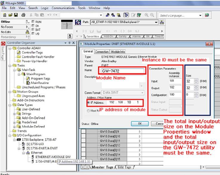
83 83
, as shown in the figure below.")
84 Q6:How to check the connections between the GW-7472 and the Modbus devices? A6:Open the GW-7472 Utility Diagnostic window, and set the UCMM values (Service = E, Class Code = 4, Instance ID = 67, Attribute ID = 3), as shown in the figure below. Click Class3 to start the connection. If the devices have been connected and receive the information from Modbus devices, the common packet will show 00. If GW-7472 couldn`t receive the information from a Modbus devices, the common packet will show 06. The status table is shown below, and it could be found in the GW-7472 manual on page

85 Service = E, Class Code = 4, Instance ID = 67, Attribute ID = 3 85

86 Q7: How can I check the wire connections? A7:There are 4-wire RS-422 wiring and 2-wire RS-485 wiring. The wire connection interface is shown below. RS-485 RS-422 The wire connections between Modbus masters and Modbus slaves must be follow the figure we show below. For non-isolated RS-422/485 ports, you should connect all signal grounds of RS-422/485 devices together. This reduces common-mode voltage between devices. 86

87 Q8:How to set up the GW-7472 for Modbus TCP? A8:In the GW-7472 configuration window, please change the Device Options to be TCP No.0 in the Modbus Request Command and fill out the Modbus device settings you want to connect with. Then, set the Server IP in the MBTCP Server Setting. Please notice that the total input/output size on the Diagnostic window and the total input/output size on the configuration window must be the same. The example settings are shown below. 87

88 Q9:How to set up GW-7472 in RSLogix 5000 MSG ladder element? A9: If you want to connect to GW-7472 with Get Attribute Single or Set Attribute Single, you can configure MSG ladder element in your routine. Please refer the steps to complete the configurations. (1)Create input/output tags and input/data data. The data type of tags are Message. The data type of data are SINT[ ]. Please notice that the size of data array (RSLogix 5000) and the size of I/O length (GW-7472) must be the same. 88
Add MSG element in your ladder and select input_tags.")

89 (2)Add a new routine. (3)Add MSG element in your ladder and select input_tags. Configure the Message Configuration. here we have to select the Service Type of Get Attribute Single. To fill in the Class as 4, Instance as 101 and Attribute 3. In the Destination dropdown box select the input_data. 89
90 Next select the Communication tab, first click on the Browse button. This will bring up a new window; here select the Ethernet module in the PLC and click OK. Now the name of the Ethernet module should be filled in at the Path, here we also have to fill in the full path to GW-7472 (in this example GW-7472 have the IP address of ). After the name of the Ethernet module in the PLC, add a comma, a space, and a 2, this indicates that the message should be routed out on Ethernet. Following the 2 add a comma, a space, and the IP-address to GW-7472, here This is everything that has to be done here, click on OK. 90


91 (4)Add MSG element in your ladder and select Output_tags. 91

92 Configure the Message Configuration. here we have to select the Service Type of Set Attribute Single. To fill in the Class as 4, Instance as 102 and Attribute 3. For Source Element select the output_data tag and the Source Length should be 4 bytes. Under Communication tab the Path should be the same as the one used to read data. (5)This is a simple example that only will issue one read request, in a normal program some logic have to be added to trigger the instruction again, for more information regarding this issue refer to documentation for RSLogix5000. Now download the program to the PLC and go Online. 92

93 If you want to send Get/Set Attribute Single continuously, you can refer to the ladder below. GW-7473 Q1: What should I do when I forget the Network Settings of GW-7473? A1:Please follow the steps to get the Network Settings: Step 1. Put the switch to Init mode. When you put the switch to Init mode, the IP address will be changed to default value: Item Settings (Init Mode) IP Gateway Mask Step 2.Select the Modbus TCP interface of GW-7473 Utility and click Connect. You can find all the network settings on the Module Configuration window. All the settings can be modify in the Init mode, but the IP address is always When you put the switch to Run mode, the IP address will change to the IP address that you modify in the Init mode. 93


94 Q2: How to get the connection status of Adapters? A2: If the adapter is connected. The back ground color of the adapter number will change to green. If the adapter is disconnected. The back ground color will change to red. ICP DAS Web Site: Contact Us ( ): 2014 by ICP DAS Co., Ltd. All Rights Reserved. 94
GW EtherNet/IP to Modbus RTU/TCP Gateway User Manual
 GW-7472 EtherNet/IP to Modbus RTU/TCP Gateway User Manual Warranty All products manufactured by ICP DAS are under warranty regarding defective materials for a period of one year, starting from the date
tsh-700 Series User Manual
 tsh-700 Series User Manual Tiny Serial Port Sharer Aug. 2017 Ver. 1.6 WARRANTY All products manufactured by ICP DAS are warranted against defective materials for a period of one year from the date of delivery
tgw-700 Series User Manual
 tgw-700 Series User Manual Warranty All products manufactured by ICP DAS are warranted against defective materials for a period of one year from the date of delivery to the original purchaser. Warning
DL-10. User Manual. RS-485 Remote Temperature and Humidity. English Ver. 1.0, Jul. 2017
 DL-10 User Manual RS-485 Remote Temperature and Humidity English Ver. 1.0, Jul. 2017 WARRANTY All products manufactured by ICP DAS are warranted against defective materials for a period of one year from
3-7 Tiny Serial-to-Ethernet Device Server & Modbus Gateway
 Tiny Serial-to- Device Server & Modbus Gateway - Tiny Serial-to- Device Server & Modbus Gateway tds-00 Series NEW tds-12 tds-00 series Tiny Serial-to- Device Server Features Incorporates any /422/485 serial
tgw-700 Series User Manual
 tgw-700 Series User Manual Ver. 2.2, Nov. 2017 WARRANTY All products manufactured by ICP DAS are warranted against defective materials for a period of one year from the date of delivery to the original
3-7 Tiny Serial-to-Ethernet Device Server & Modbus Gateway
 Tiny Serial-to-Ethernet Device Server & Modbus Gateway - Tiny Serial-to-Ethernet Device Server & Modbus Gateway tds-00 Series tds-12 tds-00 series tdsm-12 Tiny Serial-to-Ethernet Device Server Features
tgw-700 Series User Manual Warranty Warning Copyright Trademark
 tgw-700 Series User Manual Tiny Modbus/TCP to RTU/ASCII Gateway Warranty All products manufactured by ICP DAS are warranted against defective materials for a period of one year from the date of delivery
ECAN-240. (Modbus TCP to 2-port CAN Bus Gateway User manual) ECAN-240 Modbus TCP to 2-port CAN Bus Gateway User Manual, Version 1.0.
 ECAN-240 Modbus TCP to 2-port CAN Bus Gateway User Manual, Version 1.0.") ECAN-240 (Modbus TCP to 2-port CAN Bus Gateway User manual) ECAN-240 Modbus TCP to 2-port CAN Bus Gateway User Manual, Version 1.0.0 Page: 1 Table of Contents Table of Contents -----------------------------------------------------------------------------2
ECAN-240 (Modbus TCP to 2-port CAN Bus Gateway User manual) ECAN-240 Modbus TCP to 2-port CAN Bus Gateway User Manual, Version 1.0.0 Page: 1 Table of Contents Table of Contents -----------------------------------------------------------------------------2
tds-700 Series User Manual
 tds-700 Series User Manual Ver.1.9.1 Tiny Serial-to-Ethernet Device Server WARRANTY All products manufactured by ICP DAS are warranted against defective materials for a period of one year from the date
tm-752n Series User Manual
 tm-752n Series User Manual Tiny Addressable Serial Converter Ver. 1.1.1/ Aug. 2014 SUPPORTS Module includes tm-7521 and tm-7522. WARRANTY All products manufactured by ICP DAS are warranted against defective
ICP DAS GW-7472 FAQ. FAQ Version 3.4. ICP DAS Co., Ltd
 ICP DAS GW-7472 FAQ FAQ Version 3.4 ICP DAS Co., Ltd. 2017-12-21 Table of Contents Q1: Could you please confirm that GW-7472 works with SLC-500 (SLC5/05) without any problems?...3 Q2: In some case, the
Warranty. Warning. Copyright. Contact Us
 M-6026U-32 16-channel Universal Input and 16-channel Universal Output Version: 1.0.0 Date: Dec. 2017 Edited by Horse Chien M-6026U-32 User Manual Version 1.0.0 Dec. 2017-1 - Warranty All products manufactured
GW-7238D J1939 to Modbus TCP Server / RTU Slave Gateway
 GW-7238D J1939 to Modbus TCP Server / RTU Slave Gateway User s Manual www.icpdas.com 1 Warranty All products manufactured by ICP DAS are under warranty regarding defective materials for a period of one
Industrial Serial Device Server
 1. Quick Start Guide This quick start guide describes how to install and use the Industrial Serial Device Server. Capable of operating at temperature extremes of -10 C to +60 C, this is the Serial Device
tds-700 Series User Manual
 tds-700 Series User Manual Ver.1.8.2 Tiny Serial-to-Ethernet Device Server WARRANTY All products manufactured by ICP DAS are warranted against defective materials for a period of one year from the date
DEFAULT IP ADDRESS
 REAL TIME AUTOMATION 2825 N. Mayfair Rd. Suite 111 Wauwatosa, WI 53222 (414) 453-5100 www.rtaautomation.com EtherNet/IP - DeviceNet Master Gateway MODBUS TCP - DeviceNet Master Gateway Copyright 2007 Real
Embedded Modbus TCP Module GS11-MT. User Manual REV 1.1. SST Automation.
 Embedded Modbus TCP Module GS11-MT User Manual REV 1.1 SST Automation E-mail: SUPPORT@SSTCOMM.COM WWW.SSTCOMM.COM Catalog 1 About the Embedded Module... 4 1.1 General...4 1.2 Features... 4 1.3 Specifications...4
Serial to Ethernet Converter
 Serial to Ethernet Converter User s Manual Version 1.1 2004 Infosystem Technology Corporation Disclaimers The information in this manual has been carefully checked and is believed to be accurate. Infosystem
ZigBee Converter User s Manual
 ZigBee Converter User s Manual Warranty All products manufactured by ICP DAS are warranted against defective materials for a period of one year from the date of delivery to the original purchaser. Warning
WIZ220IO / WIZ220IO-EVB User s Manual (Ver. 1.0)
") [ 텍스트입력 ] WIZ0IO / WIZ0IO-EVB User s Manual (Ver. 1.0) 010 WIZnet Inc. All Rights Reserved. For more information, visit our website at www.wiznet.co.kr Document History Information Revision Data Description
[ 텍스트입력 ] WIZ0IO / WIZ0IO-EVB User s Manual (Ver. 1.0) 010 WIZnet Inc. All Rights Reserved. For more information, visit our website at www.wiznet.co.kr Document History Information Revision Data Description
GW-7228 J1939/Modbus RTU Slave Gateway
 GW-7228 J1939/Modbus RTU Slave Gateway User s Manual www.icpdas.com GW-7228 J1939/Modbus RTU Slave Gateway User s Manual (Ver 1.2, May/2011) ------------- 1 Warranty All products manufactured by ICP DAS
Ethernet I/O Module by ICP DAS Co., Ltd. All Rights Reserved. Comparison Item tpet PETL-7000 PET-7000 CPU 32-bit ARM Ethernet
 Providing networking ability and various digital I/O functions, the PETL-7000 and tet/tpet series are IP-based Ethernet I/O monitoring and control modules. The module can be remotely controlled through
INDEX. Document Name : User Manual for SC10EJ Serial to Ethernet Converter
 Document Name : User Manual for SC10EJ Serial to Ethernet Converter Page 1 of 10 INDEX 1. Technical Specifications 1 2. Modes of Operation 1 3. Configuring the SC10 EJ : Through Serial Port 2 a. Configuring
ICP DAS EIP-2000 FAQ. FAQ Version 1.1. ICP DAS Co., Ltd
 ICP DAS EIP-2000 FAQ FAQ Version 1.1 ICP DAS Co., Ltd. 2017-12-21 Table of Contents Q1:How to connect to the Allen-Bradley PLC?...3 Q2:How to use EDS file of EIP-2000 series?...7 Q3: When I click the Network
ICP DAS. ICP DAS 2015 M2M WLAN Wireless Solutions
 ICP DAS 2015 M2M WLAN Wireless Solutions Industrial Computer Industrial Product Data Computer Acquisition Product System Data Acquisition System PAC WLAN Wireless Solutions Wi-Fi Products WLAN Converter
I-7560U/7561U/7563U. User Manual WARRANTY WARNING COPYRIGHT TRADEMARKS CONTACT US
 I-7560U/7561U/7563U User Manual USB tto RS--232//422//485 Converrtterrss Verr.. 1..0,, Decc.. 2013 WARRANTY All products manufactured by ICP DAS are warranted against defective materials for a period of
Motortronics VirtualSCADA VS2-MT Communication Gateway VS2-MT User Manual Revision
 Motortronics VirtualSCADA VS2-MT Communication Gateway VS2-MT User Manual Revision 1.03.00 Motortronics / Phasetronics 1600 Sunshine Drive Clearwater, Florida 33765 Tel: 727-573-1819 Fax: 727-573-1803
MGate TM EIP3000 DF1 to EtherNet/IP Gateway User s Manual
 MGate TM EIP3000 DF1 to EtherNet/IP Gateway User s Manual First Edition, June 2009 www.moxa.com/product 2009 Moxa Inc. All rights reserved. Reproduction without permission is prohibited. MGate EIP3000
Chapter 5: Communications 5 1 SR55 Communications Overview 5 2
 Chapter 5 Table of Contents Chapter 5: Communications 5 1 SR55 Communications Overview 5 2 Modbus Serial Communications Overview 5 2 Modbus TCP Network Communications Overview 5 2 EtherNet/IP Network Communications
EGW1-IA3-MB User s Manual
 www.exemys.com Rev. 0 1 Products are in constant evolution to satisfy our customer needs. For that reason, the specifications and capabilities are subject to change without prior notice. Updated information
NetBiter Serial Server User Manual
 User Manual IntelliCom Innovation AB Linjegatan 3D SE-302 50 Halmstad SWEDEN Phone +46 35 18 21 70 Fax +46 35 17 29 09 email info@intellicom.se web www.intellicom.se Revision List Revision Date Author
tds-700/ tds-700 RevB Series
 SUPPORT Models supported include tds-712, tds-722, tds-732, tds-715, tds-725, tds-735, tds-718, tds-724 and tds-734, tdsm-712, tds-712i, tds-722i, tds-732i, tds-715i, tds-725i, tds-735i, tds-718i, tds-724i,
The I-7530A-MR Modbus RTU to CAN Converter
 The I-7530A-MR Modbus RTU to CAN Converter User s Manual Warranty All products manufactured by ICP DAS are under warranty regarding defective materials for a period of one year from the date of delivery
Serial to Ethernet Converter HL-SE02P-V1. User s Manual V3.606
 Serial to Ethernet Converter HL-SE02P-V1 User s Manual V3.606 UContents Table Welcome... 2 Package Contents. 2 Feature. 2 Application 3 Specification. 4 Hardware Guide 5 Ping Assignments. 6 Factory Default
PRODUCT PROFILE & OUTLINE...6
 Warning Please read this instruction carefully before use and follow this instruction to operate the device in order to prevent damages on the device or injuries to staff. Switch off the power before wiring.
NCOM SERIAL DEVICE SERVER 4XX SERIES USER S MANUAL
 NCOM SERIAL DEVICE SERVER 4XX SERIES USER S MANUAL 2017-07-07 Edition Titan Electronics Inc. Web: www.titan.tw Contents 1. INTRODUCTION... 4 1.1 Key Features... 5 1.2 Specifications... 6 2. PANEL LAYOUT
IPM-01 / IPM-01H MODBUS TCP/RTU Bridge User Guide
 VxI Power Ltd. IPM-01 / IPM-01H MODBUS TCP/RTU Bridge User Guide 01/12/2015 Document Number: 14970-020A Issue Number: 2 Contents 1.0 Device Overview... 2 2.0 Getting Started... 3 2.1 Connecting the Device...
Outline. EtherNet/IP Introduction EtherNet/IP products EtherNet/IP Ring Topology Implicit and Explicit Message Applications
 EtherNet/IP Outline EtherNet/IP Introduction EtherNet/IP products EtherNet/IP Ring Topology Implicit and Explicit Message Applications Outline EtherNet/IP Introduction EtherNet/IP products EtherNet/IP
i-7550 PROFIBUS to RS-232/422/485 Converter User's Manual High Quality, Industrial Data Acquisition, and Control Products
 i-7550 PROFIBUS to RS-232/422/485 Converter User's Manual High Quality, Industrial Data Acquisition, and Control Products i-7550 PROFIBUS to RS-232/422/485 Converter User's Manual (Version 1.01) PAGE:1
NCOM SERIAL DEVICE SERVER 1XX SERIES USER S MANUAL
 NCOM SERIAL DEVICE SERVER 1XX SERIES USER S MANUAL 2017-07-07 Edition Titan Electronics Inc. Web: www.titan.tw Contents 1. INTRODUCTION... 4 1.1 Key Features... 5 1.2 Specifications... 6 2. PANEL LAYOUT
NA User Manual. Copyright(C) * CREVIS Co.,Ltd * Support * URL :
 * CREVIS Co.,Ltd * Support * URL :") - 1 - List of Revisions No. Date Version Revision 1 2007.12.15 1.00 Created - 2 - Contents 1. Product Specification 1) General Specifications 2) MODUBS/TCP Communication Specification 2. MODBUS Setting
- 1 - List of Revisions No. Date Version Revision 1 2007.12.15 1.00 Created - 2 - Contents 1. Product Specification 1) General Specifications 2) MODUBS/TCP Communication Specification 2. MODBUS Setting
User Manual Anybus Serial Server
 User Manual Anybus Serial Server Rev. 1.20:1 HMS Industrial Networks AB Germany Japan Sweden U.S.A UK + 49-721 - 96472-0 + 81-45 - 478-5340 + 46-35 - 17 29 20 + 1-773 - 404-3486 + 44 (0) 1908-359301 ge-sales@hms-networks.com
MDA-8000 DIO User Manual
 MDA-8000 DIO User Manual Warranty All products manufactured by Maxthermo-Gitta are under warranty regarding defective materials for a period of one year from the date of delivery to the original purchaser.
I-7550E PROFIBUS/Ethernet Converter. User's Manual
 I-7550E PROFIBUS/Ethernet Converter User's Manual High Quality, Industrial Data Acquisition, and Control Products I-7550E PROFIBUS/Ethernet Converter User Manual (Version 100, June/2014) PAGE: 1 Warranty
J1939/Modbus Slave Gateway FAQ
 J1939/Modbus Slave Gateway FAQ Version 1.0 (For GW-7228/GW-7238D) ICP DAS Co., Ltd. Table of Contents J1939/Modbus Slave Gateway FAQ v1.0 Q01 : How to solve CAN Bus Transmission Fail problem?... 2 Q02
MGate MB3000 Modbus Gateway User Manual
 MGate MB3000 Modbus Gateway User Manual Sixth Edition, July 2012 www.moxa.com/product 2012 Moxa Inc. All rights reserved. MGate MB3000 Modbus Gateway User s Manual The software described in this manual
Winsonic MODBUS Remote IO user manual Rev. 1.0
 Winsonic MODBUS Remote IO user manual Rev. 1.0 Model: LEGAL NOTICE Warranty All products manufactured by Winsonic are under warranty regarding defective materials for a period of one year, beginning from
rbox610 Series Robust Din-rail Fanless Embedded System Web Configuration and App Software User s Manual
 rbox610 Series Robust Din-rail Fanless Embedded System Web Configuration and App Software User s Manual Disclaimers This manual has been carefully checked and believed to contain accurate information.
Industrial 1-port RS422/485 Modbus Gateway IMG-110T
 Industrial 1-port RS422/485 Modbus Gateway IMG-110T Presentation Outlines Product Positioning Applications Product Overview Comparison Product Benefits Appendix Product Features 2 / 43 Product Positioning
HART / EtherNet/IP Gateway GT200-HT-EI User Manual V 1.0 REV A SST Automation
 HART / EtherNet/IP Gateway GT200-HT-EI V 1.0 REV A SST Automation E-mail: SUPPORT@SSTCOMM.COM WWW.SSTCOMM.COM Catalog 1 Product Overview... 4 1.1 Product Function...4 1.2 Product Features... 4 1.3 Technical
TouchPAD TPD/VPD Series HMI Device User Manual
 TouchPAD TPD/VPD Series HMI Device User Manual Version 1.1.0, Jul. 2015 WARRANTY All products manufactured by ICP DAS are warranted against defective materials for a period of one year from the date of
HRT-710. User s Manual Version HRT-710 User Manual (Version 1.23, Dec/2012) PAGE: 1
 PAGE: 1") TM HRT-710 User s Manual Version 1.23 HRT-710 User Manual (Version 1.23, Dec/2012) PAGE: 1 Warranty All products manufactured by ICP DAS are under warranty regarding defective materials for a period of
TM HRT-710 User s Manual Version 1.23 HRT-710 User Manual (Version 1.23, Dec/2012) PAGE: 1 Warranty All products manufactured by ICP DAS are under warranty regarding defective materials for a period of
WM-120. Serial to Ethernet Module. Serial to Ethernet Module. User Manual. Version 1.0. Infosystem Technology Corporation, Ltd.
 W M - 1 2 0 User Manual Version 1.0 Infosystem Technology Corporation, Ltd. Index 1. Disclaimers... 1. A. Warranty... 2. B. Trademark... 2. 2. Product Information... 3. A. Introduction... 3. B. Features...
SK CU4-EIP-C Part number:
 SK CU4-EIP-C Part number: 275 271 519 EtherNet/IP Internal Bus Interface The bus interface may only be installed and commissioned by qualified electricians. An electrician is a person who, because of their
Quick Start Manual G2-2 Series with Ethernet Interface
 Getting Started This is a brief document designed to quickly get you started setting up your valve manifold with integrated G2-2 series EtherNet/IP communication protocol. 1) Initial Unpacking and Inspection
HART 710. User s Manual Version HART-710 User Manual (Version 1.00, July/2010) PAGE: 1
 PAGE: 1") TM HART 710 User s Manual Version 1.00 HART-710 User Manual (Version 1.00, July/2010) PAGE: 1 Warranty All products manufactured by ICP DAS are under warranty regarding defective materials for a period
TM HART 710 User s Manual Version 1.00 HART-710 User Manual (Version 1.00, July/2010) PAGE: 1 Warranty All products manufactured by ICP DAS are under warranty regarding defective materials for a period
User Manual A08. User Manual
 A08 TABLE OF CONTENTS TABLE OF CONTENTS... 1 1. INTRODUCTION... 2 1.1. Key Features... 3 1.2. OS Requirement... 4 1.3. Specification... 4 1.4. Packing List... 4 2. OVERVIEW... 5 2.1. LED Definition...
MGate MB3000 Modbus Gateway User s Manual
 User s Manual Seventh Edition, May 2013 www.moxa.com/product 2013 Moxa Inc. All rights reserved. User s Manual The software described in this manual is furnished under a license agreement and may be used
ZT-2570/ZT All products manufactured by ICP DAS are under warranty regarding
 Warranty Warning Copyright ZT-2570/ZT-2571 User Manual All products manufactured by ICP DAS are under warranty regarding defective materials for a period of one year, beginning from the date of delivery
DUCM Hardware. Niobrara Research & Development Corporation P.O. Box 3418 Joplin, MO USA
 DUCM Hardware Manual DUCM Hardware Installation Manual This manual covers the DUCM hardware features and installation procedures. Effective: May 29, 2015 Niobrara Research & Development Corporation P.O.
GW-7662 User Manual. Version 1.00, Jan Written by Ryan Lin
 GW-7662 User Manual Version 1.00, Jan. 2015 Written by Ryan Lin Warranty All products manufactured by ICP DAS are under warranty regarding defective materials for a period of one year, beginning from the
Any device, including routers and hosts, is running an implementation of IP address Host
 INSTRUCTION MANUAL IM471-U v0.1 EMI-10L Introduction EMI-10L converter lets you convert a serial RS485 communications port on a bus Ethernet with TCP / IP. The concepts and terms commonly used in the TCP
PX Serial - Quick Start Guide
 PX Serial - Quick Start Guide 1. Introduction To take advantage of the full range of features, we recommend you read the softcopy User Guide after performing the Quick Start procedure. It s in PDF format
EtherNet /IP User Guide
 EtherNet /IP User Guide Trademark Notices Comtrol, DeviceMaster, and PortVision are registered trademarks of Comtrol Corporation. ControlLogix, PLC-5 and Rockwell Automation are registered trademarks of
MODBUS TCP/IP TO MODBUS SERIAL GATEWAY. MODEL No: MGate-1024-DC VER 2.0
 MODBUS TCP/IP TO MODBUS SERIAL GATEWAY MODEL No: MGate-1024-DC VER 2.0 MILLENNIUM TECHNOLOGIES 440, MASTER MIND 1, ROYAL PALMS ESTATE AAREY MILK COLONY, GOREGAON (EAST), MUMBAI-400065. INDIA. PH: - 91-22-65229736,
TCP/IP TO SERIAL (SINGLE PORT) MODEL No: SerEth-1P VER 2.0
 MODEL No: SerEth-1P VER 2.0") TCP/IP TO SERIAL (SINGLE PORT) MODEL No: SerEth-1P VER 2.0 MILLENNIUM TECHNOLOGIES 440, MASTER MIND 1, ROYAL PALMS ESTATE AAREY MILK COLONY, GOREGAON (EAST), MUMBAI-400065. INDIA. PH: - 91-22-65229736,
TCP/IP TO SERIAL (SINGLE PORT) MODEL No: SerEth-1P VER 2.0 MILLENNIUM TECHNOLOGIES 440, MASTER MIND 1, ROYAL PALMS ESTATE AAREY MILK COLONY, GOREGAON (EAST), MUMBAI-400065. INDIA. PH: - 91-22-65229736,
RS232/RS485/RS422 to TCP/IP Converter ITEM NO.: RS007
 RS232/RS485/RS422 to TCP/IP Converter ITEM NO.: RS007 RS007 is a universal data converter which support serial RS232, RS422 and RS485 to the TCP / IP intelligent communication converter, it offers RS485/RS422
USR-K1 Super Port. File version: V1.0.4
 USR-K1 Super Port File version: V1.0.4 USR-K1 is the high performance-cost version of Super Port.It is an embedded serial networking module, whose function is to realize bidirectional transparent transmission
Intelligent 4 Port RS-422/485 to 2 Port Ethernet Serial Device Server with PoE
 ids6p www.is5com.com Intelligent 4 Port RS-422/485 to 2 Port Ethernet Serial Device Server with PoE Features Redundant Dual Ethernet Ports: Recovery time < 10ms Ethernet Switch Mode: Allows daisy chaining
3.7. Tiny Serial-to-Ethernet Device Server and Modbus Gateway
 Tiny SerialtoEthernet Device Server and Modbus Gateway.. Tiny SerialtoEthernet Device Server and Modbus Gateway Programmable Device Servers (SerialtoEthernet) Introduction tds00 Series Tiny SerialtoEthernet
ET-2200 Series Ethernet I/O Modules User Manual
 ET-2200 Series Ethernet I/O Modules User Manual Ethernet I/O Module Ver. 1.3.0, Jun. 2018 WARRANTY All products manufactured by ICP DAS are warranted against defective materials for a period of one year
Communications guide. Line Distance Protection System * F1* GE Digital Energy. Title page
 Title page GE Digital Energy D90 Plus Line Distance Protection System Communications guide D90 Plus firmware revision:.9x GE publication code: 60-9070-F (GEK-3469) GE Digital Energy 650 Markland Street
ETHERNET/MFC 010 Technical Datasheet
 ETHERNET/MFC 010 Technical Datasheet EtherNet/IP interface box in combination with MFC 010 Seamless integration into EtherNet/IP environments Integrated web server for easy configuration, maintenance and
The I-7530A RS-232/485/422 to CAN Converter
 The I-7530A RS-232/485/422 to CAN Converter User s Manual Warranty All products manufactured by ICP DAS are under warranty regarding defective materials for a period of one year from the date of delivery
User Manual SUPPORT. Ethernet I/O Modules Ver. 1.8, Jan. 2014
 PETL/tET/tPET DIO Series User Manual Ethernet I/O Modules Ver. 1.8, Jan. 2014 WARRANTY All products manufactured by ICP DAS are warranted against defective materials for a period of one year from the date
Industrial 2-port RS422/485 Modbus Gateway
 2-port RS422/485 Serial Interface Two RS422/485 ports with 5-contact terminal block Cost effective for RS422/ to Fast Ethernet 10/100BASE- TX application Supports 4-wire RS422 or 2-wire with 5-contact
UA-5000 Series User Manual
 ICP DAS CO., LTD. UA-5000 Series User Manual IIoT Communication Server ICP DAS CO., LTD. All Rights Reserved. www.icpdas.com Warranty All products manufactured by ICP DAS are under warranty regarding defective
2-Port RS-232/422/485 Serial over IP Ethernet Device Server Installation Guide
 2-Port RS-232/422/485 Serial over IP Ethernet Device Server Installation Guide Introduction The 2-Port RS-232/422/485 Serial over IP Ethernet Device Server is designed to operate serial ports over 10/100
Intech Micro 2300-A8VI analogue input station MODBUS RTU slave application supplementary manual.
 Intech Micro 2300-A8VI analogue input station MODBUS RTU slave application supplementary manual. MODBUS supplementary manual to the 2300-A8VI Installation Guide. The 2300 series stations are designed to
USER S MANUAL. PH485Ex1. #1 RS-485 Serial Port to Ethernet, Terminal Server/Client. Doc No: PH485Ex1-UM-001 IPEX. (IP Electronix)
") USER S MANUAL PH485Ex1 Doc No: PH485Ex1-UM-001 #1 RS-485 Serial Port to Ethernet, Terminal Server/Client IPEX (IP Electronix) Contents 1. INTRODUCTION... 3 2. SPECIFICATIONS... 3 3. PACKAGE CHECKLIST...
USER S MANUAL PH485Ex1 Doc No: PH485Ex1-UM-001 #1 RS-485 Serial Port to Ethernet, Terminal Server/Client IPEX (IP Electronix) Contents 1. INTRODUCTION... 3 2. SPECIFICATIONS... 3 3. PACKAGE CHECKLIST...
MB40 & MB45 MODBUS TCP/IP Gateway Handbook
 MB40 & MB45 MODBUS TCP/IP Gateway Handbook Version 1.2 29 July 2014 Environdata Australia Pty Ltd 42-44 Percy Street Warwick Queensland 4370 Australia Phone: (07) 4661 4699 Fax: (07) 4661 2485 International
1) Examine exterior of package for signs of damage. Report any damage to shipping carrier.
 Examine exterior of package for signs of damage. Report any damage to shipping carrier.") I P MAC AD D RE S S Getting Started This is a brief document designed to quickly get you started setting up your valve manifold with an integrated Numatics G2-2 Series EtherNet/IP communication node. 1)
I P MAC AD D RE S S Getting Started This is a brief document designed to quickly get you started setting up your valve manifold with an integrated Numatics G2-2 Series EtherNet/IP communication node. 1)
Tel: Fax:
 NP302 Series 2-port RS-232 232/485/422 to Ethernet Serial Server User manual Shenzhen 3onedata Technology Co.,Ltd Tel: +86-755-26702688 Fax: +86-755-26703485 www.3onedata.com Contents 1. Introduction...
TRP-C37 User s Manual
 TRP-C37 User s Manual Ethernet to RS232/422/485 Converter Printed Oct. 2010 Rev 1.0 Trycom Technology Co., Ltd 1F, No.2-11, Sihu street, Yingge Township, Taipei, Taiwan ROC Tel: 886-2-86781191, Fax: 886-2-86781172
SSE232-LE Serial Server- User s Manual
 www.exemys.com Rev.6 1 Products are in constant evolution to satisfy our customer needs. For that reason, the specifications and capabilities are subject to change without prior notice. Updated information
WiFi 16 Relay Board TCP ModBus Controlled - User Manual 21 Aug WiFi 16 Relay Board TCP ModBus Controlled
 WiFi 16 Relay Board TCP ModBus Controlled User Manual Date: -1- Content 1. Specification... 4 2. Applications examples... 5 2.1. Control electrical devices wirelessly... 5 2.2. Control electrical devices
USR-TCP Hard version: V2.0 File version: V
 Serial Device Server - RS232/RS485 to Ethernet converter USR-TCP232-300 Hard version: V2.0 File version: V1.1 2011-8-17 Serial Device Server - RS232/RS485 to Ethernet converter is an Equipment for convert
User Manual Gateway component for EtherNet/IP
 User Manual Gateway component for EtherNet/IP PR100066 1/7/2016 Table of Contents KUNBUS GmbH Table of Contents 1 General Information... 3 1.1 Disclaimer... 3 1.2 Notes Regarding this User Manual... 4
Tritex II EtherNet/IP - Option
 Tritex II EtherNet/IP - Option Tritex II Ethernet/IP Option.doc 10/15/13 REV B 952-368-3434 Tritex II EtherNet/IP Option.doc 2 10/15/13 Contents 1. General... 5 1.1. IP Address... 6 1.2. Network Classes...
Operation Manual of EX9132CST-Series
 Operation of EX9132CST-Series Serial to TCP/IP Converter (EX9132CST-2/ EX9132CST-RS485/ EX9132C-RS232) Version 1.0.0. 30.03.2017 Table of Contents 1 Introduction... 4 2 Overview... 5 2. 1 Package Checklist...
TRP-C37. Ethernet to RS232/422/485 Converter. User s Manual. Printed Apr.2014 Rev 1.3
 TRP-C37 Ethernet to RS232/422/485 Converter User s Manual Printed Apr.2014 Rev 1.3 Trycom Technology Co.,Ltd No.35, Zhongxing Rd., Guishan Township, Taoyuan County 333, Taiwan. Tel : 886-3-350-3351 Fax:
Quick Start Hardware Testing Environment Connection Default Parameter Data Transmission Testing
 File version:v1.0 1 / 35 ... 1 1. Quick Start...4 1.1. Hardware Testing Environment... 4 1.2. Connection...4 1.3. Default Parameter... 5 1.4. Data Transmission Testing...5 2. Overview...6 2.1. Brief Introduction...6
PWR. Power Module Slots
 INSTRUCTION MANUAL ETHERNET INTERFACE MODULE (Modbus/TCP) MODEL BEFORE USE... Thank you for choosing M-System. Before use, please check the contents of the package you received as outlined below. If you
Document Name: User Manual for SC10EK4 Serial to Ethernet Converter with 4 TCP Sockets. Index
 Document Name: User Manual for SC10EK4 Serial to Ethernet Converter with 4 TCP Sockets. Index Technical Specifications 1 Installation Procedure 1 LED Indications 2 Configuration Procedure Configuration
# Byrne Rd, Burnaby, BC, V5J 3J1, Canada Phone: or
 EQ7000 User Manual Rev 1.04 www.equustek.com Revision 1.04 Feb 20th, 2017 #286-5489 Byrne Rd, Burnaby, BC, V5J 3J1, Canada Phone: 888-387-3787 or 604-266-8547 www.equustek.com Page 1 Contents INTRODUCTION...4
User Manual Edition: v a
 WPC-832-Con 2 Ports Modbus TCP to Modbus RTU Wi-Fi, Ethernet connection Data Concentrator User Manual Edition: v.201809a http://www.tcpipweb.com Table of Contents Introduction------------------------------------------------------------------------------------------------------------------------------
USER S MANUAL. PH232Ex1. #1 RS-232 Serial Port to Ethernet, Terminal Server/Client. Doc No: PH232Ex1-UM-001 IPEX. (IP Electronix)
") USER S MANUAL PH232Ex1 Doc No: PH232Ex1-UM-001 #1 RS-232 Serial Port to Ethernet, Terminal Server/Client IPEX (IP Electronix) Contents 1. INTRODUCTION... 3 2. SPECIFICATIONS... 3 3. PACKAGE CHECKLIST...
USER S MANUAL PH232Ex1 Doc No: PH232Ex1-UM-001 #1 RS-232 Serial Port to Ethernet, Terminal Server/Client IPEX (IP Electronix) Contents 1. INTRODUCTION... 3 2. SPECIFICATIONS... 3 3. PACKAGE CHECKLIST...
Intech Micro 2300-RO4 analogue input station MODBUS RTU slave application supplementary manual.
 Intech Micro 2300-RO4 analogue input station MODBUS RTU slave application supplementary manual. MODBUS supplementary manual to the 2300-RO4 Installation Guide. The 2300 series stations are designed to
EQ7000. User Manual. Rev 1.00
 EQ7000 User Manual Rev 1.00 www.equustek.com Revision 1.00 February 27, 2009 Contents INTRODUCTION...4 ABOUT THIS MANUAL...4 INTENDED AUDIENCE...4 HARDWARE SPECIFICATIONS...5 PHYSICAL SPECIFICATIONS...5