Pepwave Device Connector User Manual. Pepwave Product: Device Connector Rugged
|
|
|
- Georgiana Shaw
- 5 years ago
- Views:
Transcription
1 Pepwave Device Connector User Manual Pepwave Product: Device Connector Rugged Pepwave Firmware 1.1 February 2017
2 Table of Contents 1. Getting Started 1.1 What s in the Box 1.2 Get to Know Your Device Connector 1.3 Access the Web Admin Interface Connect by Ethernet Connect by Wi-Fi 1.4 Choose Your Connection Mode 2 Configuring the LAN interface(s) 2.1 Network Settings 2.2 Port Setting 3 Configuring the WAN Interface(s) 4 AP 3.1 Wi-Fi WAN Settings (Wi-Fi Mode Only) Wireless Networks Creating Wi-Fi Connection Profiles 3.2 WAN Health Check 4.1 Wireless SSID 4.2 Settings 5 System Settings 5.1 Admin Security 5.2 Operating Mode 5.3 Firmware 5.4 Time 5.5 Schedule 5.6 Notification 5.7 Event Log 5.8 SNMP 5.9 InControl 5.10 Configuration 5.11 Feature Add-ons
3 5.12 Reboot 6 Tools 6.1 Ping 6.2 Traceroute 6.3 Wake-on-LAN 7 PEPVPN 8 Port Forwarding 9 NAT Mappings 10 QoS 10.1 Bandwidth Control 10.2 Application Application Prioritization Prioritization for Custom Applications DSL/Cable Optimization 11 Miscellaneous Settings 11.1 Certificate Manager 12 Status 12.1 Device 12.2 Client List 12.3 PepVPN 12.4 Event Log 12.5 Bandwidth Real Time Hourly Daily Monthly Appendix


4 1. Getting Started 1.1 What s in the Box DCS-RUG 12V power supply 3x dual-band 5dBi omni antenna 1.2 Get to Know Your Device Connector Device Connector Rugged
. Your PC should be set up as follow on the Internet Protocol (TCP/IP) Properties or Network screen:")
5 1.3 Access the Web Admin Interface There are two ways to access the Web Admin page Connect by Ethernet To access the Web Admin page by Ethernet, your PC must be in the same subnet as the Device Connector (i.e X). Your PC should be set up as follow on the Internet Protocol (TCP/IP) Properties or Network screen:
6 1.3.2 Connect by Wi-Fi Connect to the SSID: PEPWAVE_XXX where XXXX represents the last four digits of your device s serial number (e.g. 7D6E). Passphrase is the last 8 hexadecimal digits of your device s LAN MAC address (e.g. DDC3CCC0) Now you are ready to start the first time configuration of the Pepwave Device Connector. On your PC, start a web browser, go to this URL: Choose Your Connection Mode The Device Connector supports only Wi-Fi connection mode. After successful login The dashboard will be displayed. The Dashboard shows current WAN and WI-FI AP.
.")
7 2 Configuring the LAN interface(s) 2.1 Network Settings LAN interface settings are located at Network>LAN>Network Settings/Port Settings. Begin setting up your physical LAN by entering IP settings (VLAN configuration will be covered following physical LAN setup). This represents the LAN interfaces that are active on your router (including VLAN). A grey X means that the VLAN is used in other settings and cannot be deleted. You can find which settings are using the VLAN by hovering over the grey X. Alternatively, a red X means that there are no settings using the VLAN. You can delete that VLAN by clicking the red X Clicking any of the existing LAN interfaces will result in the following IP Settings IP Address & Subnet Mask Enter the Device Connector s IP address and subnet mask values to be used on the LAN. To enable multiple VLANs, press the

8 DHCP Server Settings DHCP Server IP Range & Subnet Mask Lease Time DNS Servers BOOTP Extended DHCP Option When this setting is enabled, the DHCP server automatically assigns an IP address to each computer that is connected via LAN and configured to obtain an IP address via DHCP. The Pepwave router s DHCP server can prevent IP address collision on the LAN. These settings allocate a range of IP addresses that will be assigned to LAN computers by the Pepwave router s DHCP server. This setting specifies the length of time throughout which an IP address of a DHCP client remains valid. Upon expiration of the lease time, the assigned IP address will no longer be valid and renewal of the IP address assignment will be required. This option allows you to input the DNS server addresses to be offered to DHCP clients. If Assign DNS server automatically is selected, the Pepwave router s built-in DNS server address (i.e., LAN IP address) will be offered. Check this box to enable BOOTP on older networks that still require it. In addition to standard DHCP options (e.g., DNS server address, gateway address, subnet mask), you can specify the value of additional extended DHCP options, as defined in RFC With these extended options enabled, you can pass additional configuration information to LAN hosts. To define an extended DHCP option, click the Add button, choose the option to define and enter its value. For values that are in IP address list format, you can enter one IP
9 address per line in the provided text area input control. Each option can be defined once only. DHCP Reservation This setting reserves the assignment of fixed IP addresses for a list of computers on the LAN. The computers to be assigned fixed IP addresses on the LAN are identified by their MAC addresses. The fixed IP address assignment is displayed as a cross-reference list between the computers names, MAC addresses, and fixed IP addresses. Name (an optional field) allows you to specify a name to represent the device. MAC addresses should be in the format of 00:AA:BB:CC:DD:EE. Press to create a new record. Press to remove a record. Reserved client information can be imported from the Client List, located at Status>Client List. For more details, please refer to Section Once configuration is complete, click Save to store the changes. To configure DHCP relay, first click the button found next to the DHCP Server option to display the settings. DHCP Relay Settings Enable DHCP Server IP Address DHCP Option 82 Check this box to turn on DHCP relay. Click the icon to disable DHCP relay. Enter the IP addresses of one or two DHCP servers in the provided fields. The DHCP servers entered here will receive relayed DHCP requests from the LAN. For active-passive DHCP server configurations, enter active and passive DHCP server relay IP addresses in DHCP Server 1 and DHCP Server 2. DCHP Option 82 includes device information as relay agent for the attached client when forwarding DHCP requests from client to server. This option also embeds the device s MAC address and network name in circuit and remote IDs. Check this box to enable DHCP Option Port Setting Port settings can be accessed at Network>Port Settings.


10 LAN Physical Settings Speed This is the port speed of the LAN interface. It should be set to the same speed as the connected device to avoid port negotiation problems. When a static speed is set, you may choose whether to advertise its speed to the peer device. Auto is selected by default. You can choose not to advertise the port speed if the port has difficulty negotiating with the peer device. 3 Configuring the WAN Interface(s) WAN Interface settings are located at Network>WAN. To reorder WAN priority, drag on the appropriate WAN by holding the left mouse button, move it to the desired priority (the first one would be the highest priority, the second one would be lower priority, and so on), and drop it by releasing the mouse button. To disable a particular WAN connection, drag on the appropriate WAN by holding the left mouse button, move it the Disabled row, and drop it by releasing the mouse button.

11 You can also set priorities on the Dashboard. Click the Details button in the corresponding row to modify the connection setting. Important Note Connection details will be changed and become effective immediately after clicking the Save and Apply button. 3.1 Wi-Fi WAN Settings (Wi-Fi Mode Only) To access Wi-Fi WAN settings, click Network>WAN Wireless Networks To see a list of available networks, click inside wireless network. To connect to a displayed network, select it from this list. To access wireless network, click Network>WAN>Wireless Networks. To access detailed WAN settings click, Network>WAN>Details.
 and Disconnect (cold standby).")

12 Wi-Fi Connection Settings WAN Connection Name Standby State MTU Reply to ICMP PING Enter a name to represent this WAN connection. This setting specifies the state of the WAN connection while in standby. The available options are Remain Connected (hot standby) and Disconnect (cold standby). This setting specifies the maximum transmission unit. By default, MTU is set to Custom You may adjust the MTU value by editing the text field. Click Default to restore the default MTU value. Select Auto and the appropriate MTU value will be automatically detected. The auto-detection will run each time the WAN connection establishes If this setting is disabled, the WAN connection will not respond to ICMP ping requests. By default, this setting is enabled. Wi-Fi WAN Settings Channel Width Available options are 20 MHz, 40 MHz, and Auto (20/40 MHz). Default is Auto (20/40 MHz), which allows both widths to be used simultaneously.

13 Channel Selection Data Rate Determine whether the channel will be automatically selected. If you select custom, the following table will appear: This option allows you to select a specific bit rate for data transfer over the device s Wi-Fi network. By default, Auto is selected. Output Power This option is for specifying the transmission output power for the Wi-Fi AP. There are 4 relative power levels available Max, High, Mid, and Low. The actual output power will be bound by the regulatory limits of the selected country. Note that selecting the Boost option may cause the MAX s radio output to exceed local regulatory limits. Roaming Connect to Any Open Mode AP Beacon Miss Counter Checking this box will enable Wi-Fi roaming. Click the icon for additional options. This option is to specify whether the Wi-Fi WAN will connect to any open mode access points it finds. This field allows you to set the frequency for the beacon to include delivery traffic indication messages. Bandwidth Allowance Monitor Action Start Day Monthly Allowance If Error! Reference source not found. is enabled, you will be notified by when usage hits 75% and 95% of the monthly allowance. If Disconnect when usage hits 100% of monthly allowance is checked, this WAN connection will be disconnected automatically when the usage hits the monthly allowance. It will not resume connection unless this option has been turned off or the usage has been reset when a new billing cycle starts. This option allows you to define which day of the month each billing cycle begins. This field is for defining the maximum bandwidth usage allowed for the WAN connection each month.

14 Health Check Settings Method This setting specifies the health check method for the WAN connection. This value can be configured as Disabled, PING, DNS Lookup, or HTTP. The default method is DNS Lookup. For mobile Internet connections, the value of Method can be configured as Disabled or SmartCheck. Health Check Disabled When Disabled is chosen in the Method field, the WAN connection will always be considered as up. The connection will NOT be treated as down in the event of IP routing errors. Health Check Method: PING ICMP ping packets will be issued to test the connectivity with a configurable target IP address or hostname. A WAN connection is considered as up if ping responses are received from either one or both of the ping hosts. PING Hosts This setting specifies IP addresses or hostnames with which connectivity is to be tested via ICMP ping. If Use first two DNS servers as Ping Hosts is checked, the target ping host will be the first DNS server for the corresponding WAN connection. Reliable ping hosts with a high uptime should be considered. By default, the first two DNS servers of the WAN connection are used as the ping hosts. Health Check Method: DNS Lookup
15 DNS lookups will be issued to test connectivity with target DNS servers. The connection will be treated as up if DNS responses are received from one or both of the servers, regardless of whether the result was positive or negative. Health Check DNS Servers This field allows you to specify two DNS hosts IP addresses with which connectivity is to be tested via DNS Lookup. If Use first two DNS servers as Health Check DNS Servers is checked, the first two DNS servers will be the DNS lookup targets for checking a connection's health. If the box is not checked, Host 1 must be filled, while a value for Host 2 is optional. If Include public DNS servers is selected and no response is received from all specified DNS servers, DNS lookups will also be issued to some public DNS servers. A WAN connection will be treated as down only if there is also no response received from the public DNS servers. Connections will be considered as up if DNS responses are received from any one of the health check DNS servers, regardless of a positive or negative result. By default, the first two DNS servers of the WAN connection are used as the health check DNS servers. Health Check Method: HTTP HTTP connections will be issued to test connectivity with configurable URLs and strings to match. URL1 URL 2 WAN Settings>WAN Edit>Health Check Settings>URL1 The URL will be retrieved when performing an HTTP health check. When String to Match is left blank, a health check will pass if the HTTP return code is between 200 and 299 (Note: HTTP redirection codes 301 or 302 are treated as failures). When String to Match is filled, a health check will pass if the HTTP return code is between 200 and 299 and if the HTTP response content contains the string. WAN Settings>WAN Edit>Health Check Settings>URL2 If URL2 is also provided, a health check will pass if either one of the tests passed. Other Health Check Settings

16 Timeout Health Check Interval Health Check Retries This setting specifies the timeout in seconds for ping/dns lookup requests. The default timeout is 5 seconds. This setting specifies the time interval in seconds between ping or DNS lookup requests. The default health check interval is 5 seconds. This setting specifies the number of consecutive ping/dns lookup timeouts after which the Peplink Balance will treat the corresponding WAN connection as down. Default health retries is set to 3. Using the default Health Retries setting of 3, the corresponding WAN connection will be treated as down after three consecutive timeouts. Recovery Retries This setting specifies the number of consecutive successful ping/dns lookup responses that must be received before the Peplink Balance treats a previously down WAN connection as up again. By default, Recover Retries is set to 3. Using the default setting, a WAN connection that is treated as down will be considered as up again upon receiving three consecutive successful ping/dns lookup responses Creating Wi-Fi Connection Profiles You can manually create a profile to connect to a Wi-Fi connection. This is useful for creating a profile for connecting to hidden SSID access points. Click Network>WAN>Details>Create Profile to get started. Clicking this will open a window similar to the one shown below.

17 Wi-Fi Connection Profile Settings Type Network Name (SSID) Security Select whether the network will connect automatically or manually. Enter a name to represent this Wi-Fi connection. This option allows you to select which security policy is used for this wireless network. Available options: Open WEP WPA/WPA2 Personal WPA/WPA2 Enterprise

18 3.2 WAN Health Check To ensure traffic is routed to healthy WAN connections only, the Pepwave router can periodically check the health of each WAN connection. The health check settings for each WAN connection can be independently configured via Network>WAN>Details. Health Check Settings Method This setting specifies the health check method for the WAN connection. This value can be configured as Disabled, PING, DNS Lookup, or HTTP. The default method is DNS Lookup. For mobile Internet connections, the value of Method can be configured as Disabled or SmartCheck. Health Check Disabled When Disabled is chosen in the Method field, the WAN connection will always be considered as up. The connection will NOT be treated as down in the event of IP routing errors. Health Check Method: PING ICMP ping packets will be issued to test the connectivity with a configurable target IP address or hostname. A WAN connection is considered as up if ping responses are received from either one or both of the ping hosts. PING Hosts This setting specifies IP addresses or hostnames with which connectivity is to be tested via ICMP ping. If Use first two DNS servers as Ping Hosts is checked, the target ping host will be the first DNS server for the corresponding WAN connection. Reliable ping hosts with a high uptime should be considered. By default, the first two DNS servers of the WAN connection are used as the ping hosts.


19 Health Check Method: DNS Lookup DNS lookups will be issued to test connectivity with target DNS servers. The connection will be treated as up if DNS responses are received from one or both of the servers, regardless of whether the result was positive or negative. Health Check DNS Servers This field allows you to specify two DNS hosts IP addresses with which connectivity is to be tested via DNS lookup. If Use first two DNS servers as Health Check DNS Servers is checked, the first two DNS servers will be the DNS lookup targets for checking a connection's health. If the box is not checked, Host 1 must be filled, while a value for Host 2 is optional. If Include public DNS servers is selected and no response is received from all specified DNS servers, DNS lookups will also be issued to some public DNS servers. A WAN connection will be treated as down only if there is also no response received from the public DNS servers. Connections will be considered as up if DNS responses are received from any one of the health check DNS servers, regardless of a positive or negative result. By default, the first two DNS servers of the WAN connection are used as the health check DNS servers. Health Check Method: HTTP HTTP connections will be issued to test connectivity with configurable URLs and strings to match. URL1 URL 2 WAN Settings>WAN Edit>Health Check Settings>URL1 The URL will be retrieved when performing an HTTP health check. When String to Match is left blank, a health check will pass if the HTTP return code is between 200 and 299 (Note: HTTP redirection codes 301 or 302 are treated as failures). When String to Match is filled, a health check will pass if the HTTP return code is between 200 and 299 and if the HTTP response content contains the string. WAN Settings>WAN Edit>Health Check Settings>URL2 If URL2 is also provided, a health check will pass if either one of the tests passed.

20 Other Health Check Settings Timeout Health Check Interval Health Check Retries Recovery Retries This setting specifies the timeout in seconds for ping/dns lookup requests. The default timeout is 5 seconds. This setting specifies the time interval in seconds between ping or DNS lookup requests. The default health check interval is 5 seconds. This setting specifies the number of consecutive ping/dns lookup timeouts after which the Pepwave router will treat the corresponding WAN connection as down. Default health retries is set to 3. Using the default Health Retries setting of 3, the corresponding WAN connection will be treated as down after three consecutive timeouts. This setting specifies the number of consecutive successful ping/dns lookup responses that must be received before the Pepwave router treats a previously down WAN connection as up again. By default, Recover Retries is set to 3. Using the default setting, a WAN connection that is treated as down will be considered as up again upon receiving three consecutive successful ping/dns lookup responses. Automatic Public DNS Server Check on DNS Test Failure When the health check method is set to DNS Lookup and health checks fail, the Pepwave router will automatically perform DNS lookups on public DNS servers. If the tests are successful, the WAN may not be down, but rather the target DNS server malfunctioned. You will see the following warning message on the main page: 4 AP Use the controls on the AP tab to set the wireless SSID and AP settings.

21 4.1 Wireless SSID Wireless network settings, including the name of the network (SSID) and security policy, can be defined and managed in this section. Click ADD to create a new network profile, or click the existing network profile to modify its settings. SSID Settings SSID Enable Broadcast SSID Data Rate A Multicast Filter A Multicast Rate A This setting specifies the SSID of the virtual AP to be scanned by Wi-Fi clients. Select Yes to enable the virtual AP. This setting specifies whether or not Wi-Fi clients can scan the SSID of this wireless network. Broadcast SSID is enabled by default. Select Auto to allow the Pepwave router to set the data rate automatically, or select Fixed and choose a rate from the displayed drop-down menu. This setting enables the filtering of multicast network traffic to the wireless SSID. This setting specifies the transmit rate to be used for sending multicast network traffic. The selected Protocol and Channel Bonding settings will affect the rate options and values available here.
22 IGMP Snooping A Layer 2 Isolation A To allow the Pepwave router to listen to internet group management protocol (IGMP) network traffic, select this option. Layer 2 refers to the second layer in the ISO Open System Interconnect model. When this option is enabled, clients on the same VLAN, SSID, or subnet are isolated to that VLAN, SSID, or subnet, which can enhance security. Traffic is passed to upper communication layer(s). By default, the setting is disabled. Security Settings Security Policy This setting configures the wireless authentication and encryption methods. Available options are Open (No Encryption), WPA/WPA2 - Personal, WPA/WPA2 Enterprise and Static WEP. Access Control Restricted Mode MAC Address List The settings allow administrator to control access using MAC address filtering. Available options are None, Deny all except listed Connection coming from the MAC addresses in this list will be either denied or accepted based the option selected in the previous field. 4.2 Settings Navigating to AP>Settings displays a screen similar to the one shown below:

23 Wi-Fi Radio Settings Operating Country Wi-Fi Antenna This option sets the country whose regulations the Pepwave router follows. Choose from the router's internal or optional external antennas, if so equipped. Important Note
24 Per FCC regulations, the country selection is not available on all models marketed in the US. All US models are fixed to US channels only. Wi-Fi AP Settings Protocol This option allows you to specify which client association requests will be accepted. By default, ng is selected. Channel Width Auto (20/40 MHz) and 20 MHz are available. The default setting is Auto (20/40 MHz), which allows both widths to be used simultaneously. Auto (80 MHz) and (20/40 MHz) are available. The default setting is 80 MHz. The two default settings are for ng and ac accordingly? Channel Output Power This option allows you to select which RF channel will be used. This option is for specifying the transmission output power for the Wi-Fi AP. There are 4 relative power levels available Max, High, Mid, and Low. The actual output power will be bound by the regulatory limits of the selected country. Maximum number of clients Enter the maximum number of clients that can simultaneously connect to the wireless network or enter 0 to allow an unlimited number of connections. Client Signal Strength Threshold A Beacon Rate A Beacon Interval A DTIM A RTS Threshold Fragmentation Threshold A This field determines that maximum signal strength each individual client will receive. The measurement unit is megawatts. This option is for setting the transmit bit rate for sending a beacon. By default, 1Mbps is selected. This option is for setting the time interval between each beacon. By default, 100ms is selected. This field allows you to set the frequency for the beacon to include a delivery traffic indication message. The interval is measured in milliseconds. The default value is set to 1 ms. Set the minimum packet size for your access point to send an RTS using the RTS/CTS handshake. Setting 0 disables this feature. Determines the maximum size (in bytes) that each packet fragment will be broken down into. Set 0 to disable fragmentation.

25 Distance/Time Converter A Slot Time A ACK Timeout A Frame Aggregation A Select the distance you want your Wi-Fi to cover in order to adjust the below parameters. Default values are recommended. This field is for specifying the wait time before the Device Connector transmits a packet. By default, this field is set to 9 µs. This field is for setting the wait time to receive an acknowledgement packet before performing a retransmission. By default, this field is set to 48 µs. This option allows you to enable frame aggregation to increase transmission throughput. 5 System Settings 5.1 Admin Security There are two types of user accounts available for accessing the web admin: admin and user. They represent two user levels: the admin level has full administration access, while the user level is read-only. The user level can access only the device's status information; users cannot make any changes on the device

26 Admin Account UI User Account UI A web login session will be logged out automatically when it has been idle longer than the Web Session Timeout. Before the session expires, you may click the Logout button in the web admin to exit the session. 0 hours 0 minutes signifies an unlimited session time. This setting should be used only in special situations, as it will lower the system security level if users do not log out before closing the browser. The default is 4 hours, 0 minutes. For security reasons, after logging in to the web admin Interface for the first time, it is recommended to change the administrator password. Configuring the administration interface to be accessible only from the LAN can further improve system security. Administrative settings configuration is located at System>Admin Security.

27 Admin Settings Router Name Admin User Name Admin Password Confirm Admin Password This field allows you to define a name for this Pepwave router. By default, Router Name is set as DCS_XXXX, where XXXX refers to the last 4 digits of the unit s serial number. Admin User Name is set as admin by default, but can be changed, if desired. This field allows you to specify a new administrator password. This field allows you to verify and confirm the new administrator password.
28 Read-only User Name User Password Confirm User Password Web Session Timeout Authentication by RADIUS Auth Protocol Auth Server Auth Server Secret Auth Timeout Accounting Server Accounting Server Secret CLI SSH & Console CLI SSH Port CLI SSH Access Security Read-only User Name is set as user by default, but can be changed, if desired. This field allows you to specify a new user password. Once the user password is set, the read-only user feature will be enabled. This field allows you to verify and confirm the new user password. This field specifies the number of hours and minutes that a web session can remain idle before the Pepwave router terminates its access to the web admin interface. By default, it is set to 4 hours. With this box is checked, the web admin will authenticate using an external RADIUS server. Authenticated users are treated as either "admin" with full read-write permission or user with read-only access. Local admin and user accounts will be disabled. When the device is not able to communicate with the external RADIUS server, local accounts will be enabled again for emergency access. Additional authentication options will be available once this box is checked. This specifies the authentication protocol used. Available options are MS-CHAP v2 and PAP. This specifies the access address and port of the external RADIUS server. This field is for entering the secret key for accessing the RADIUS server. This option specifies the time value for authentication timeout. This specifies the access address and port of the external accounting server. This field is for entering the secret key for accessing the accounting server. The CLI (command line interface) can be accessed via SSH. This field enables CLI support. For additional information regarding CLI. This field determines the port on which clients can access CLI SSH. This menu allows you to choose between granting access to LAN and WAN clients, or to LAN clients only. This option is for specifying the protocol(s) through which the web admin interface can be accessed: HTTP


29 HTTPS HTTP/HTTPS Web Admin Port Web Admin Access This field is for specifying the port number on which the web admin interface can be accessed. This option is for specifying the network interfaces through which the web admin interface can be accessed: LAN only LAN/WAN If LAN/WAN is chosen, the WAN Connection Access Settings form will be displayed. 5.2 Operating Mode Operating Mode can be accessed at System>Operating Mode. The operating mode can be changed between Router or Bridge Mode. Operating Mode Operating Mode Your device can act as a bridge or as a router, depending on your selection here. 5.3 Firmware Pepwave router firmware is upgradeable through the web admin interface. Firmware upgrade functionality is located at System>Firmware.

30 There are two ways to upgrade the unit. The first method is through an online download. The second method is to upload a firmware file manually. To perform an online download, click on the Check for Firmware button. The Pepwave router will check online for new firmware. If new firmware is available, the Pepwave router will automatically download the firmware. The rest of the upgrade process will be automatically initiated. You may also download a firmware image from the Peplink website and update the unit manually. To update using a firmware image, click Choose File to select the firmware file from the local computer, and then click Manual Upgrade to send the firmware to the Pepwave router. It will then automatically initiate the firmware upgrade process. Please note that all Peplink devices can store two different firmware versions in two different partitions. A firmware upgrade will always replace the inactive partition. If you want to keep the inactive firmware, you can simply reboot your device with the inactive firmware and then perform the firmware upgrade. Important Note The firmware upgrade process may not necessarily preserve the previous configuration, and the behavior varies on a case-by-case basis. Consult the release notes for the particular firmware version before installing. Do not disconnect the power during firmware upgrade process. Do not attempt to upload a non-firmware file or a firmware file that is not supported by Peplink. Upgrading the Pepwave router with an invalid firmware file will damage the unit and may void the warranty. Important Note If the firmware is rolled back from 5.x to 4.x, the configurations will be lost. 5.4 Time Time Settings enables the system clock of the Pepwave router to be synchronized with a specified time server. Time settings are located at System>Time.


31 Time Settings Time Zone Time Server This specifies the time zone (along with the corresponding Daylight Savings Time scheme). The Time Zone value affects the time stamps in the Pepwave router s event log and notifications. Check Show all to show all time zone options. This setting specifies the NTP network time server to be utilized by the Pepwave router. 5.5 Schedule Enable and disable different functions (such as WAN connections, outbound policy, and firewalls at different times, based on a user-scheduled configuration profile. The settings for this are located at System > Schedule

32 Edit Schedule Profile Enabling Name Schedule Click this checkbox to enable this schedule profile. Note that if this is disabled, then any associated features will also have their scheduling disabled. Enter your desired name for this particular schedule profile. Click the drop-down menu to choose pre-defined schedules as your starting point. Please note that upon selection, previous changes on the schedule map will be deleted Notification notification functionality provides a system administrator with up-to-date information on network status. The settings for configuring notifications are found at System> Notification. Notification Settings Notification SMTP Server This setting specifies whether or not to enable notification. If Enable is checked, the Pepwave router will send messages to system administrators when the WAN status changes or when new firmware is available. If Enable is not checked, notification is disabled and the Pepwave router will not send messages. This setting specifies the SMTP server to be used for sending . If the server requires authentication, check Require authentication.

33 SSL Encryption SMTP Port SMTP User Name / Password Confirm SMTP Password Sender s Address Recipient s Address Check the box to enable SMTPS. When the box is checked, SMTP Port will be changed to 465 automatically. This field is for specifying the SMTP port number. By default, this is set to 25 ; when SSL Encryption is checked, the default port number will be set to 465. You may customize the port number by editing this field. Click Default to restore the number to its default setting. This setting specifies the SMTP username and password while sending . These options are shown only if Require authentication is checked in the SMTP Server setting. This field allows you to verify and confirm the new administrator password. This setting specifies the address the Pepwave router will use to send reports. This setting specifies the address(es) to which the Pepwave router will send notifications. For multiple recipients, separate each addresses using the enter key. After you have finished setting up notifications, you can click the Test Notification button to test the settings before saving. After Test Notification is clicked, you will see this screen to confirm the settings: Click Send Test Notification to confirm. In a few seconds, you will see a message with detailed test results.


34 5.7 Event Log Event log functionality enables event logging at a specified remote syslog server. The settings for configuring the remote system log can be found at System>Event Log. Event Log Settings Remote Syslog Remote Syslog Host Push Events This setting specifies whether or not to log events at the specified remote syslog server. This setting specifies the IP address or hostname of the remote syslog server. The Pepwave router can also send push notifications to mobile devices that have our Mobile Router Utility installed. Check the box to activate this feature. For more information on the Router Utility, go to: SNMP SNMP or simple network management protocol is an open standard that can be used to collect information about the Pepwave router. SNMP configuration is located at System>SNMP.


35 SNMP Settings SNMP Device Name SNMP Port This field shows the router name defined at System>Admin Security. This option specifies the port which SNMP will use. The default port is 161. SNMPv1 This option allows you to enable SNMP version 1. SNMPv2 This option allows you to enable SNMP version 2. SNMPv3 This option allows you to enable SNMP version InControl InControl is a cloud-based service which allows you to manage all of your Peplink and Pepwave devices with one unified system. With it, you can generate reports, gather statistics, and configure your devices automatically. All of this is now possible with InControl.

36 When this check box is checked, the device's status information will be sent to the Peplink InControl system. This device's usage data and configuration will be sent to the system if you enable the features in the system. Alternately, you could also privately host InControl. Simply check the box beside the Privately Host InControl open, and enter the IP Address of your InControl Host. You can sign up for an InControl account at You can register your devices under the account, monitor their status, see their usage reports, and receive offline notifications 5.10 Configuration Backing up Pepwave router settings immediately after successful completion of initial setup is strongly recommended. The functionality to download and upload Pepwave router settings is found at System>Configuration. Note that available options vary by model. Configuration Restore Configuration to Factory Settings Download Active Configurations Upload Configurations The Restore Factory Settings button is to reset the configuration to factory default settings. After clicking the button, you will need to click the Apply Changes button on the top right corner to make the settings effective. Click Download to backup the current active settings. To restore or change settings based on a configuration file, click Choose File to locate the configuration file on the local computer, and then click Upload. The new settings can then be applied by clicking the Apply Changes button on the page header, or you can cancel the procedure by pressing discard on the main page of the web admin interface.

 is the current system boot up firmware. Please note that a firmware upgrade will always replace the inactive firmware partition. 6 Tools 6.")
37 5.11 Feature Add-ons Pepwave devices have features that can be activated upon purchase. Once the purchase is complete, you will receive an activation key. Enter the key in the Activation Key field, click Activate, and then click Apply Changes 5.12 Reboot This page provides a reboot button for restarting the system. For maximum reliability, the Pepwave router can equip with two copies of firmware. Each copy can be a different version. You can select the firmware version you would like to reboot the device with. The firmware marked with (Running) is the current system boot up firmware. Please note that a firmware upgrade will always replace the inactive firmware partition. 6 Tools 6.1 Ping The ping test tool sends pings through a specified Ethernet interface or a VPN connection. You can specify the number of pings in the field Number of times, to a maximum number of 10 times. Packet Size can be set to a maximum of 1472 bytes. The ping utility is located at System>Tools>Ping, illustrated below:

38 Tip A system administrator can use the ping utility to manually check the connectivity of a particular LAN/WAN connection. 6.2 Traceroute The traceroute test tool traces the routing path to the destination through a particular Ethernet interface or a SpeedFusion TM connection. The traceroute test utility is located at System>Tools>Traceroute. Peplink routers can send magical Packets

39 Tip A system administrator can use the traceroute utility to analyze the connection path of a LAN/WAN connection. 6.3 Wake-on-LAN Peplink routers can send special magic packets to any client specified from the Web UI. To access this feature, navigate to System>Tools>Wake-on-LAN. Select a client from the drop-down list and click Send to send a magic packet.
 will be able to route to local subnets. Note that all LAN subnets and the subnets behind them must be unique.")
40 7 PEPVPN To configure PepVPN and SpeedFusion, navigate to Advanced>PepVPN The local LAN subnet and subnets behind the LAN (defined under Static Route on the LAN settings page) will be advertised to the VPN. All VPN members (branch offices and headquarters) will be able to route to local subnets. Note that all LAN subnets and the subnets behind them must be unique. Otherwise, VPN members will not be able to access each other.

41 All data can be routed over the VPN using the 256-bit AES encryption standard. To configure, navigate to Advanced>PepVPN and click the New Profile button to create a new VPN profile (you may have to first save the displayed default profile in order to access the New Profile button). Each profile specifies the settings for making VPN connection with one remote Pepwave or Peplink device. Click the Save button to create and save a new VPN connection profile for making a VPN connection. PepVPN Profile Settings Name Active Encryption This field is for specifying a name to represent this profile. The name can be any combination of alphanumeric characters (0-9, A-Z, a-z), underscores (_), dashes (-), and/or non-leading/trailing spaces ( ). When this box is checked, this VPN connection profile will be enabled. Otherwise, it will be disabled. By default, VPN traffic is encrypted with 256-bit AES. If Off is selected on both sides of a VPN connection, no encryption will be applied.
42 Authentication Remote ID / Pre-shared Key NAT Mode Remote IP Address / Host Names (Optional) Data Port Bandwidth Limit Cost Select from By Remote ID Only, Preshared Key. When selecting By Remote ID Only, be sure to enter a unique peer ID number in the Remote ID field. This optional field becomes available when Remote ID / Pre-shared Key is selected as the Peplink Balance s VPN Authentication method, as explained above. Pre-shared Key defines the pre-shared key used for this particular VPN connection. The VPN connection's session key will be further protected by the pre-shared key. The connection will be up only if the pre-shared keys on each side match. When the peer is running firmware 5.0+, this setting will be ignored. Check this box to allow the local DHCP server to assign an IP address to the remote peer. When NAT Mode is enabled, all remote traffic over the VPN will be tagged with the assigned IP address using network address translation. If NAT Mode is not enabled, you can enter a remote peer s WAN IP address or hostname(s) here. If the remote uses more than one address, enter only one of them here. Multiple hostnames are allowed and can be separated by a space character or carriage return. Dynamic-DNS host names are also accepted. This field is optional. With this field filled, the Peplink Balance will initiate connection to each of the remote IP addresses until it succeeds in making a connection. If the field is empty, the Peplink Balance will wait for connection from the remote peer. Therefore, at least one of the two VPN peers must specify this value. Otherwise, VPN connections cannot be established. This field is used to specify a UDP port number for transporting outgoing VPN data. If Default is selected, UDP port 4500 will be used. Port will be used if the remote unit uses Firmware prior to version 5.4 or if port 4500 is unavailable. If Custom is selected, enter an outgoing port number from 1 to Define maximum download and upload speed to each individual peer. This functionality requires the peer to use PepVPN version or above. Define path cost for this profile. OSPF will determine the best route through the network using the assigned cost. Default: 10 8 Port Forwarding pepwave device connector can act as a firewall that blocks, by default, all inbound access from the internet. By using port forwarding, Internet users can access servers behind the pepwave router. Inbound port forwarding rules can be defined at Advanced>Port Forwarding. To define a new service, click Add Service.

43 Port Forwarding Settings Enable Service Name IP Protocol Port This setting specifies whether the inbound service takes effect. When Enable is checked, the inbound service takes effect: traffic is matched and actions are taken by the Pepwave router based on the other parameters of the rule. When this setting is disabled, the inbound service does not take effect: the Pepwave router disregards the other parameters of the rule. This setting identifies the service to the system administrator. Valid values for this setting consist of only alphanumeric and underscore _ characters. The IP Protocol setting, along with the Port setting, specifies the protocol of the service as TCP, UDP, ICMP, or IP. Traffic that is received by the Pepwave router via the specified protocol at the specified port(s) is forwarded to the LAN hosts specified by the Servers setting. Please see below for details on the Port and Servers settings. Alternatively, the Protocol Selection Tool drop-down menu can be used to automatically fill in the protocol and a single port number of common Internet services (e.g. HTTP, HTTPS, etc.). After selecting an item from the Protocol Selection Tool drop-down menu, the protocol and port number remain manually modifiable. The Port setting specifies the port(s) that correspond to the service, and can be configured to behave in one of the following manners: Any Port, Single Port, Port Range, Port Map, and Range Mapping Any Port : all traffic that is received by the Pepwave router via the specified protocol is forwarded to the servers specified by the Servers setting. For example, with IP Protocol set to TCP, and Port set to Any Port, all TCP traffic is forwarded to the configured servers.
44 Single Port : traffic that is received by the Pepwave router via the specified protocol at the specified port is forwarded via the same port to the servers specified by the Servers setting. For example, with IP Protocol set to TCP, and Port set to Single Port and Service Port 80, TCP traffic received on port 80 is forwarded to the configured servers via port 80. Port Range : traffic that is received by the Pepwave router via the specified protocol at the specified port range is forwarded via the same respective ports to the LAN hosts specified by the Servers setting. For example, with IP Protocol set to TCP, and Port set to Port Range and Service Ports 80-88, TCP traffic received on ports 80 through 88 is forwarded to the configured servers via the respective ports. Port Mapping : traffic that is received by Pepwave router via the specified protocol at the specified port is forwarded via a different port to the servers specified by the Servers setting. For example, with IP Protocol set to TCP, and Port set to Port Mapping, Service Port 80, and Map to Port 88, TCP traffic on port 80 is forwarded to the configured servers via port 88. (Please see below for details on the Servers setting.) Range Mapping : traffic that is received by the Pepwave router via the specified protocol at the specified port range is forwarded via a different port to the servers specified by the Servers setting. Inbound IP Address(es) Server IP Address This setting specifies the WAN connections and Internet IP address(es) from which the service can be accessed. This setting specifies the LAN IP address of the server that handles the requests for the service. 9 NAT Mappings NAT mappings allow IP address mapping of all inbound and outbound NAT traffic to and from an internal client IP address. Settings to configure NAT mappings are located at Advanced>NAT Mappings. To add a rule for NAT mappings, click Add NAT Rule.
 in order to facilitate inbound and outbound traffic.")
45 NAT Mapping Settings LAN Client(s) Address Inbound Mappings Outbound Mappings NAT mapping rules can be defined for a single LAN IP Address, an IP Range, or an IP Network. This refers to the LAN host s private IP address. The system maps this address to a number of public IP addresses (specified below) in order to facilitate inbound and outbound traffic. This option is only available when IP Address is selected. This setting specifies the WAN connections and corresponding WAN-specific Internet IP addresses on which the system should bind. Any access to the specified WAN connection(s) and IP address(es) will be forwarded to the LAN host. This option is only available when IP Address is selected in the LAN Client(s) field. This setting specifies the WAN IP addresses that should be used when an IP connection is made from a LAN host to the Internet. Each LAN host in an IP range or IP network will be evenly mapped to one of each selected WAN's IP addresses (for better IP address utilization) in a persistent manner (for better application compatibility).
. 10.2")
46 10 QoS 10.1 Bandwidth Control You can define a maximum download speed (over all WAN connections) and upload speed (for each WAN connection) that each individual Staff and Guest member can consume. No limit can be imposed on individual Manager members. By default, download and upload bandwidth limits are set to unlimited (set as 0 ) Application Application Prioritization Three application priority levels can be set: High, Normal, and Low. Pepwave device connectors can detect various application traffic types by inspecting the packet content. Select an application by choosing a supported application, or by defining a custom application manually. The priority preference of supported applications is placed at the top of the table. Custom applications are at the bottom Prioritization for Custom Applications Click the Add button to define a custom application. Click the button in the Action column to delete the custom application in the corresponding row. When Supported Applications is selected, the Pepwave router will inspect network traffic and prioritize the selected applications. Alternatively, you can select Custom Applications and define the application by providing the protocol, scope, port number, and DSCP value.

47 DSL/Cable Optimization DSL/cable-based WAN connections have lower upload bandwidth and higher download bandwidth. When a DSL/cable circuit's uplink is congested, the download bandwidth will be affected. Users will not be able to download data at full speed until the uplink becomes less congested. DSL/Cable Optimization can relieve such an issue. When it is enabled, the download speed will become less affected by the upload traffic. By default, this feature is enabled. 11 Miscellaneous Settings 11.1 Certificate Manager This section allows you to assign certificates for web admin SSL. The local keys will not be transferred to another device by any means. 12 Status 12.1 Device System information is located at Status>Device
48 System Information Router Name Model Product Code Hardware Revision Serial Number Firmware PepVPN Version Hostname Uptime System Time This is the name specified in the Router Name field located at System>Admin Security. This shows the model name and number of this device. If your model uses a product code, it will appear here. This shows the hardware version of this device. This shows the serial number of this device. This shows the firmware version this device is currently running. This shows the current PepVPN version. The host name assigned to the Pepwave router appears here. This shows the length of time since the device has been rebooted. This shows the current system time.
, click.")
49 Diagnostic Report Remote Assistance The Download link is for exporting a diagnostic report file required for system investigation. Click Turn on to enable remote assistance. The second table shows the MAC address of each LAN/WAN interface connected. To view your device s End User License Agreement (EULA), click. Important Note If you encounter issues and would like to contact the Pepwave Support Team ( ), please download the diagnostic report file and attach it along with a description of your issue Client List The client list table is located at Status>Client List. It lists DHCP and online client IP addresses, names (retrieved from the DHCP reservation table or defined by users), current download and upload rate, and MAC address. Clients can be imported into the DHCP reservation table by clicking the button on the right. You can update the record after import by going to Network>LAN PepVPN
 status and subnet information of each VPN peer.")

50 Current PepVPN status information is located at Status>PepVPN. Click on the corresponding peer name to explore the WAN connection(s) status and subnet information of each VPN peer.click the button for a chart displaying real-time throughput, latency, and drop-rate information for each WAN connection 12.4 Event Log Event log information is located at Status>EventLog The log section displays a list of events that has taken place on the Pepwave router. Check Auto Refresh to refresh log entries automatically. Click the Clear Log button to clear the log.

51 12.5 Bandwidth This section shows bandwidth usage statistics and is located at Status>Bandwidth. Bandwidth usage at the LAN while the device is switched off (e.g., LAN bypass) is neither recorded nor shown Real Time The Data transferred since installation table indicates how much network traffic has been processed by the device since the first bootup. The Data transferred since last reboot table indicates how much network traffic has been processed by the device since the last boot up Hourly This page shows the hourly bandwidth usage for all WAN connections, with the option of viewing each individual connection. Select the desired connection to check from the drop-down menu.

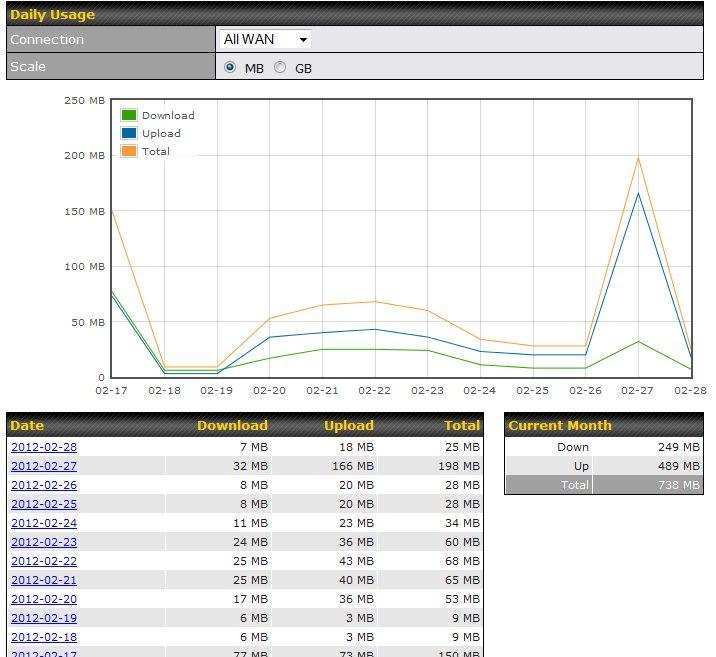
52 Daily This page shows the daily bandwidth usage for all WAN connections, with the option of viewing each individual connection. Select the connection to check from the drop-down menu. If you have enabled the Bandwidth Monitoring feature, the Current Billing Cycle table for that WAN connection will be displayed. Click on a date to view the client bandwidth usage of that specific date. This feature is not available if you have selected to view the bandwidth usage of only a particular WAN connection. The scale of the graph can be set to display megabytes ( MB ) or gigabytes ( GB ).
53

54 Monthly All WAN Monthly Bandwidth Usage
Peplink SD Switch User Manual. Published on October 25th, 2018
 Peplink SD Switch User Manual Published on October 25th, 2018 1 Table of Contents Switch Layout 4 Specifications 5 Hardware Overview 6 Quick Start Functions 7 Reset Switch 7 Connect Ethernet 7 Connect
Peplink SD Switch User Manual
 Peplink SD Switch User Manual Peplink Products: Peplink SD Switch 8-ports/24-ports/48-ports Peplink SD Switch Firmware 1.2.0 Published on December 10, 2018 Copyright & Trademarks Copyright & trademark
Security SSID Selection: Broadcast SSID:
 69 Security SSID Selection: Broadcast SSID: WMM: Encryption: Select the SSID that the security settings will apply to. If Disabled, then the device will not be broadcasting the SSID. Therefore it will
Peplink Balance Multi-WAN Routers
 Peplink Balance Multi-WAN Routers Model 20/30/210/310/380/390/580/710/1350 User Manual Firmware 5.1 September 10 Copyright & Trademarks Specifications are subject to change without prior notice. Copyright
Pepwave AP One Series: AP One Enterprise / AP One AC mini / AP One Rugged / AP One Flex / AP Pro AC
 Pepwave AP One Series: AP One Enterprise / AP One AC mini / AP One Rugged / AP One Flex / AP Pro AC October 2018 Table of Contents Introduction and Scope 5 Product Features and Benefits 6 Package Contents
Pepwave AP One Series: AP One/ AP One 300M / AP One mini / AP One Flex / AP One In-Wall
 Pepwav eapser i es Us ermanual APOne/APOne300M /APOnemi ni /APOneFl ex/aponei nwal l /APPr o Pepwave AP One Series: AP One/ AP One 300M / AP One mini / AP One Flex / AP One In-Wall Pepwave AP Pro Series:
WISNETWORKS. WisOS 11ac V /3/21. Software version WisOS 11ac
 WISNETWORKS User Manual V1.1 2016/3/21 Software version 1.0.0021 Table of contents 1. Setup& WMI... 3 1.1 Hardware Setup... 3 1.2 Web Management Interface... 3 2. Status... 4 2.1 Overview... 4 2.1.1 System...
Section 3 - Configuration. Enable Auto Channel Scan:
 Enable Auto Channel Scan: Wireless Channel: The Auto Channel Scan setting can be selected to allow the DGL-4500 to choose the channel with the least amount of interference. Indicates the channel setting
Wireless LAN Device Series CPE2615. User Manual. v
 Wireless LAN Device Series CPE2615 User Manual v20080312 Preface To use this guide, you should have experience working with the TCP/IP configuration and be familiar with the concepts and terminology of
Wireless LAN Device Series CPE2615. User Manual. v
 Wireless LAN Device Series CPE2615 User Manual v20081230 Preface To use this guide, you should have experience working with the TCP/IP configuration and be familiar with the concepts and terminology of
Peplink Balance: 20 / 30 / 30 LTE / 50 / One / 210 / 310 / 305 HW2 / 380 HW6 / 580 HW2-3 / 710 HW3 / 1350 HW2 / 2500
 Firmware 7 Release Notes Release Date 01/18/2017 Contents 1. Devices Supported 2. Firmware 7 Compatibility - Unsupported Models 3. Important Notices 4. Obtaining the Firmware 5. Feature Improvements 6.
ZAC Product Specification
 ZAC-1023-5-13 Part Number: ZN-7200-2AEI-L Product Specification IEEE 802.11 a/n CPE Version: 0.6-1 - 2 Specification 2.1 Hardware Specification Table 2-1 Hardware Specification Features Chipset Standard
A5500 Configuration Guide
 A5500 Configuration Guide Sri Ram Kishore February 2012 Table of contents Gateway Configuration... 3 Accessing your gateway configuration tool... 3 Configuring your broadband Internet access... 3 Configuring
Grandstream Networks, Inc. GWN76xx Wi-Fi Access Points Master/Slave Architecture Guide
 Grandstream Networks, Inc. GWN76xx Wi-Fi Access Points Master/Slave Architecture Guide Table of Contents INTRODUCTION... 4 DISCOVER AND PAIR GWN76XX ACCESS POINTS... 5 Discover GWN76xx... 5 Method 1: Discover
DWR G Integrated Access Device. User Manual
 DWR-923 4G Integrated Access Device User Manual TABLE OF CONTENTS 1. GETTING TO KNOW THE DWR-923... 2 1.1 Introduction... 2 1.2 Package Contents... 3 1.3 System Requirements... 3 1.4 Hardware Overview
CHAPTER 7 ADVANCED ADMINISTRATION PC
 ii Table of Contents CHAPTER 1 INTRODUCTION... 1 Broadband ADSL Router Features... 1 Package Contents... 3 Physical Details... 4 CHAPTER 2 INSTALLATION... 6 Requirements... 6 Procedure... 6 CHAPTER 3 SETUP...
Wireless-G Router User s Guide
 Wireless-G Router User s Guide 1 Table of Contents Chapter 1: Introduction Installing Your Router System Requirements Installation Instructions Chapter 2: Preparing Your Network Preparing Your Network
OSBRiDGE 24XL(i) Configuration Manual. Firmware 2.05b9
 Configuration Manual. Firmware 2.05b9") OSBRiDGE 24XL(i) Configuration Manual Firmware 2.05b9 1. Initial setup and configuration. OSBRiDGE 24XL devices are configurable via WWW interface. Each device uses following default settings: IP: 192.168.1.250
OSBRiDGE 24XL(i) Configuration Manual Firmware 2.05b9 1. Initial setup and configuration. OSBRiDGE 24XL devices are configurable via WWW interface. Each device uses following default settings: IP: 192.168.1.250
Peplink Balance: 20 / 30 / 30 LTE / 50 / One / 210 / 310 / 305 HW2 / 380 HW6 / 580 HW2-3 / 710 HW3 / 1350 HW2 / 2500
 Firmware 7.1.1 Release Notes Release Date: Aug 14th, 2018 Contents 1. Devices Supported 2. Firmware 7 Compatibility - Unsupported Models 3. Important Notices 4. Obtaining the Firmware 5. New Features 6.
802.11a g Dual Band Wireless Access Point. User s Manual
 802.11a+802.11g Dual Band Wireless Access Point User s Manual 0 Chapter 1 Introduction 1.1 Feature Fully interoperable with IEEE 802.11b compliant products. High-Speed data transfer rate up to 11Mbps.
AplombTech Smart Router Manual
 AplombTech Smart Router Manual (Version: 1.0) 1 Version & Purpose Version Manual version V 1.0 Explanation Corresponds to the initial version of device Purpose This manual describes the function features
Linksys E2000 Advanced Wireless-N Router. User Guide
 User Guide Table of Contents Contents Chapter 1: Product Overview 1 Top....................................................... 1 Back...................................................... 1 Horizontal
LevelOne FBR User s Manual. 1W, 4L 10/100 Mbps ADSL Router. Ver
 LevelOne FBR-1416 1W, 4L 10/100 Mbps ADSL Router User s Manual Ver 1.00-0510 Table of Contents CHAPTER 1 INTRODUCTION... 1 FBR-1416 Features... 1 Package Contents... 3 Physical Details... 3 CHAPTER 2
IP806GA/GB Wireless ADSL Router
 IP806GA/GB Wireless ADSL Router 802.11g/802.11b Wireless Access Point ADSL Modem NAT Router 4-Port Switching Hub User's Guide Table of Contents CHAPTER 1 INTRODUCTION... 1 Wireless ADSL Router Features...
UIP1869V User Interface Guide
 UIP1869V User Interface Guide (Firmware version 0.1.8 and later) Table of Contents Opening the UIP1869V's Configuration Utility... 3 Connecting to Your Broadband Modem... 5 Setting up with DHCP... 5 Updating
User Guide TL-R470T+/TL-R480T REV9.0.2
 User Guide TL-R470T+/TL-R480T+ 1910012468 REV9.0.2 September 2018 CONTENTS About This Guide Intended Readers... 1 Conventions... 1 More Information... 1 Accessing the Router Overview... 3 Web Interface
QUICK START GUIDE. Pepwave Express. Quick Start Guide. Pepwave Express. Nov Pepwave
 Quick Start Guide Nov-12 http://www.pepwave.com 1 Copyright @ 2012 Pepwave First Time Setup 1. Default Configuration IP: 192.168.0.1 Subnet Mask: 255.255.255.0 2. Network Configuration acts as a CPE bridge
Cisco Small Business RV320/RV325 Gigabit Dual WAN VPN Router
 ADMINISTRATION GUIDE Cisco Small Business RV320/RV325 Gigabit Dual WAN VPN Router 78-20928-02 Contents Chapter 1: Getting Started 7 Using the Getting Started Window 7 Features of the User Interface 8 Chapter
Peplink Balance Multi-WAN Bonding Routers
 Peplink Balance Multi-WAN Bonding Routers User Manual For Models: ONE/20/30/30 LTE/50/210/310/305/380/580/710/1350/2500 MediaFast 200/500 Peplink Balance Firmware 6.2.1 June 2015 Copyright & trademark
MultiAP 700G. User Manual
 MultiAP 700G User Manual Aug-12 COPYRIGHT & TRADEMARKS Specifications are subject to change without notice. Copyright 2012 ValuePoint Networks. All Rights Reserved. ValuePoint and the VP logo are trademarks
airhaul Nexus sb3010
 u n w i r i n g o u r w o r l d TM airhaul Nexus sb3010 User Configuration Guide Version 1.3 Copyright smartbridges Pte Ltd. All Rights Reserved. About This Document This Software Configuration Guide is
Pepwave Routers User Manual
 Pepwave Routers User Manual Pepwave Products: MAX 700/HD2/HD2 IP67/HD2 mini/hd4/br1/br1 IP55/BR2 IP55/On-The-Go MAX HD2/HD4 with MediaFast Surf SOHO Pepwave Firmware 6.1 December 2014 COPYRIGHT & TRADEMARKS
Pepwave MAX and Surf User Manual
 Pepwave MAX and Surf User Manual Pepwave Products: MAX 700/HD2/HD2 IP67/HD2 mini/hd4/transit/hotspot/br1/br1 Mini/BR1 Slim/BR1 ENT/BR1 Pro LTE/BR1 IP55/BR2 IP55/On-The-Go/MAX HD2/HD4 with MediaFast/Device
WISNETWORKS. WisOS 11ac V /3/21. Software version WisOS 11ac
 WISNETWORKS User Manual V1.1 2016/3/21 Software version 1.0.0021 Table of contents 1. Setup& WMI... 3 1.1 Hardware Setup... 3 1.2 Web Management Interface... 3 2. Status... 4 2.1 Overview... 4 2.1.1 System...
WL5041 Router User Manual
 TECOM WL5041 Router User Manual TECOM CO., LTD. March 2003 2003 by TECOM CO., LTD. All rights reserved. Printed in Taiwan Table of contents Package Contents--------------------------------------- 2 Installing
Table of contents
 GD-GEO20 1 2 Table of contents 1 Conventions Used in this Document... 4 Abbreviation List... 5 2 Packing list... 7 3 Introduction... 8 3.1 Deployment Scenarios... 8 3.1.1 HotSpot... 8 3.1.2 Point to Multipoint...
Oct 2007 Version 1.01
 Oct 2007 Version 1.01 Table of Contents Introduction...4 System Requirement...4 Getting Started...4 Installing the Smart WLAN Manager...5 Discovering the Switch and AP...9 Understanding the Screen Layout...12
Preface. Manual Revisions. Revision Date Description 1.0 March 3, 2009 DAP-3520 Revision A1 with firmware version Trademarks
 Preface D-Link reserves the right to revise this publication and to make changes in the content hereof without obligation to notify any person or organization of such revisions or changes. Manual Revisions
CWA-854HT 54 Mbps Wireless-G High Transmission Access Point User s Guide
 CWA-854HT 54 Mbps Wireless-G High Transmission Access Point User s Guide May 2006 Version 1.00 1 Table of Contents Table of Contents... 2 List of Figures... 4 List of Tables... 6 Chapter 1. Introduction...
SMALL BUSINESS. Model 20/30/50 30 LTE One 210/ BPL-210 BPL-310
 BRANCH/SMALL OFFICE SMALL BUSINESS MID-SIZE BUSINESS LARGE ENTERPRISE/CAMPUS Model 20/30/50 30 LTE One 210/310 305 380 580 710 1350 2500 Product Code BPL-021 BPL- BPL- BPL-210 BPL-305 BPL-380 BPL-580 BPL-710
User Manual Gemtek WiMAX Modem
 User Manual Gemtek WiMAX Modem WIXS-177 CONTENTS Chapter 1 Overview...1-1 1.1. Indoor CPE... 1-1 1.2. Outdoor CPE... 1-2 Chapter 2 WEB-GUI...2-3 2.1. System Configuration Login... 2-3 2.2. System Logout...
Pepwave MAX and Surf User Manual
 Pepwave MAX and Surf User Manual Pepwave Products: MAX 700/HD2/HD2 IP67/HD2 mini/hd4/transit/br1/br1 Slim/BR1 ENT/BR1 Pro LTE/BR1 IP55/BR2 IP55/On-The-Go/MAX HD2/HD4 with MediaFast/Device Connector/ Surf
PePWave Mesh Connector User Manual
 PePWave Mesh Connector User Manual Document Rev. 1.0 Jun-07 COPYRIGHT & TRADEMARKS Specifications are subject to change without notice. Copyright 1999-2007 PePWave Ltd. All Rights Reserved. PePWave and
Table of contents
 1 GD-GEO20-TP 2 Table of contents 1 Conventions Used in this Document... 4 Abbreviation List... 4 2 Packing list... 6 3 Introduction... 7 3.1 Deployment Scenarios... 7 3.1.1 HotSpot... 7 3.1.2 Point to
Broadband Router. User s Manual
 Broadband Router User s Manual 1 Introduction... 4 Features... 4 Minimum Requirements... 4 Package Content... 4 Note... 4 Get to know the Broadband Router... 5 Back Panel... 5 Front Panel... 6 Setup Diagram...7
PowerStation2 LiteStation2 LiteStation5 User s Guide
 PowerStation2 LiteStation2 LiteStation5 User s Guide Copyright 2007 Ubiquiti Networks Inc. All rights reserved. Contents INTRODUCTION...2 QUICK SETUP GUIDE...3 CONFIGURATION GUIDE...7 Main Settings...8
DPX8000 Series Deep Service Switching Gateway User Configuration Guide BRAS Service Board Module v1.0
 DPX8000 Series Deep Service Switching Gateway User Configuration Guide BRAS Service Board Module v1.0 i Hangzhou DPtech Technologies Co., Ltd. provides full- range technical support. If you need any help,
WRE2206. User s Guide. Quick Start Guide. Wireless N300 Range Extender. Default Details. Version 1.00 Edition 1, 01/2015
 WRE2206 Wireless N300 Range Extender Version 1.00 Edition 1, 01/2015 Quick Start Guide User s Guide Default Details Web Address http://zyxelsetup OR http://192.168.1.2 www.zyxel.com User Name admin Password
Peplink Balance Multi-WAN Bonding Routers
 Peplink Balance Multi-WAN Bonding Routers User Manual For Models: ONE/20/30/30 LTE/50/210/310/305/380/580/710/1350/2500 MediaFast 200/500 Peplink Balance Firmware 6.1 June 2014 Copyright & trademark specifications
802.11ac Wireless Access Point Model WAC104
 Point Model WAC104 User Manual October 2016 202-11698-01 350 E. Plumeria Drive San Jose, CA 95134 USA Support Thank you for purchasing this NETGEAR product. You can visit www.netgear.com/support to register
Wireless-N Pocket AP/Router ETR9360. Wireless N Pocket AP/Router V1.0
 Wireless-N Pocket AP/Router ETR9360 Wireless N Pocket AP/Router V1.0 1 1. Package Contents...5 2. System Requirements...5 3. Introduction...6 4. Features...7 5. Hardware Overview...8 6. Before you Begin...10
User Guide LAPN300. Wireless-N300. Access Point with POE. Model # LAPN300
 User Guide LAPN300 Wireless-N300 Access Point with POE Model # LAPN300 1 Contents Chapter 1 Quick Start Guide... 5 Mounting Guide... 6 Wall Installation... 6 Ceiling Installation... 6 Chapter 2 Access
XG-520 Wireless b/g Portable Router. User s Manual
 XG-520 Wireless 802.11b/g Portable Router User s Manual FCC Certifications This equipment has been tested and found to comply with the limits for a Class B digital device, pursuant to Part 15 of the FCC
LAPAC1200. AC1200 Dual Band Access Point. User's Guide
 LAPAC1200 AC1200 Dual Band Access Point User's Guide TABLE OF CONTENTS CHAPTER 1 QUICK START GUIDE... 1 Package Contents... 1 Physical Details... 1 Mounting Guide... 3 CHAPTER 2 ACCESS POINT SETUP...
Barracuda Link Balancer
 Barracuda Networks Technical Documentation Barracuda Link Balancer Administrator s Guide Version 2.3 RECLAIM YOUR NETWORK Copyright Notice Copyright 2004-2011, Barracuda Networks www.barracuda.com v2.3-111215-01-1215
PepwaveMAX Series: MAX 700 / HD2/HD2 IP67 / HD2 mini / HD4 / BR1/ BR1 IP55/ BR2 IP55 / On-The-Go MAX HD2 with MediaFast / MAX HD4 with MediaFast
 PepwaveMAX Series: MAX 700 / HD2/HD2 IP67 / HD2 mini / HD4 / BR1/ BR1 IP55/ BR2 IP55 / On-The-Go MAX HD2 with MediaFast / MAX HD4 with MediaFast Pepwave MAX Firmware 6.1 June 2014 COPYRIGHT & TRADEMARKS
User Guide. For TP-Link Auranet Access Points
 User Guide For TP-Link Auranet Access Points EAP110 / EAP115 / EAP225 / EAP245 / EAP320 / EAP330 / EAP115-Wall / EAP110-Outdoor 1910012276 REV 2.0.2 October 2017 CONTENTS About this User Guide... 1 Overview...
Dual WAN VPN Firewall VPN 3000 User s Guide. Version 1.0 Date : 1 July 2005 Please check for the latest version
 Dual WAN VPN Firewall VPN 3000 User s Guide Version 1.0 Date : 1 July 2005 Please check www.basewall.com for the latest version Basewall 2005 TABLE OF CONTENTS 1: INTRODUCTION... 4 Internet Features...
TABLE OF CONTENT 1. ABOUT THIS GUIDE Overview of the User s Guide INTRODUCTION Overview Features...
 TABLE OF CONTENT 1. ABOUT THIS GUIDE... 3 1.1 Overview of the User s Guide... 3 2. INTRODUCTION... 3 2.1 Overview... 3 2.2 Features... 3 2.3 Panel Layout... 4 2.3.1 Front Panel... 4 2.3.2 Rear Panel...
User Guide. Omada Controller Software
 User Guide Omada Controller Software 1910012506 REV 3.2.0 March 2019 CONTENTS 1 Quick Start... 1 1.1 Determine the Network Topology...2 1.1.1 Management on the local Network... 2 1.1.2 Management via Cloud
Light Mesh AP. User s Guide. 2009/2/20 v1.0 draft
 Light Mesh AP User s Guide 2009/2/20 v1.0 draft i FCC Certifications This equipment has been tested and found to comply with the limits for a Class B digital device, pursuant to Part 15 of the FCC Rules.
Peplink Balance: 20 / 30 / 30 LTE / 50 / One / 210 / 310 / 305 HW2 / 380 HW6 / 580 HW2-3 / 710 HW3 / 1350 HW2 / 2500
 Firmware 7.1 Release Notes Release Date: 02/01/2018 Contents 1. Devices Supported 2. Firmware 7 Compatibility - Unsupported Models 3. Important Notices 4. Obtaining the Firmware 5. New Features 6. Feature
IEEE a/b/g/n Wireless LAN Access Point. AT-MWS AP series. Reference Manual
 IEEE 802.11a/b/g/n Wireless LAN Access Point AT-MWS AP series Reference Manual Table of Contents 1 Before You Begin 5 1.1 Considerations for Wireless Installation...6 Computer Settings...6 Hardware Installation...9
D-Link Central WiFiManager Configuration Guide
 Table of Contents D-Link Central WiFiManager Configuration Guide Introduction... 3 System Requirements... 3 Access Point Requirement... 3 Latest CWM Modules... 3 Scenario 1 - Basic Setup... 4 1.1. Install
FlyBoost CL100 USER MANUAL A02-OCL100 A02-OCL100_ME01
 FlyBoost CL100 A02-OCL100 USER MANUAL A02-OCL100_ME01 Table of Contents OVERVIEW THE PRODUCT... 1 Introduction... 1 Features and Benefits... 2 When to Use Which Mode... 3 Access Point Client Mode... 3
NBG-416N. Wireless N-lite Home Router. Default Login Details. IMPORTANT! READ CAREFULLY BEFORE USE.
 NBG-416N Wireless N-lite Home Router IMPORTANT! Default Login Details LAN IP https://192.168.1.1 Address User Name admin Password 1234 READ CAREFULLY BEFORE USE. KEEP THIS GUIDE FOR FUTURE REFERENCE. IMPORTANT!
Wireless Access Point
 802.11g / 802.11b / WPA Wireless Access Point User Guide TABLE OF CONTENTS CHAPTER 1 INTRODUCTION... 1 Features of your Wireless Access Point... 1 Package Contents... 4 Physical Details... 4 CHAPTER 2
MIMO Wireless Broadband Route r User s Manual 1
 MIMO Wireless Broadband Router User s Manual 1 Introduction...4 Features...4 Minimum Requirements...4 Package Content...4 Note...4 Get to know the Broadband Router...5 Back Panel...5 Front Panel...6 Setup
MRD-310 MRD G Cellular Modem / Router Web configuration reference guide. Web configuration reference guide
 Web configuration reference guide 6623-3201 MRD-310 MRD-330 Westermo Teleindustri AB 2008 3G Cellular Modem / Router Web configuration reference guide www.westermo.com Table of Contents 1 Basic Configuration...
A Division of Cisco Systems, Inc. Dual-Band. GHz g a. Dual-Band. Wireless A+G. Access Point. User Guide WIRELESS WAP55AG. Model No.
 A Division of Cisco Systems, Inc. Dual-Band 5 GHz 802.11a + GHz 2.4 802.11g WIRELESS Dual-Band Wireless A+G Access Point User Guide Model No. WAP55AG Copyright and Trademarks Specifications are subject
Wireless Broadband Router
 LW6005A-R2 Wireless Broadband Router Manual 1 Introduction... 4 Features... 4 Minimum Requirements... 4 Package Content... 4 Note... 4 Get to know the Broadband Router... 5 Back Panel... 5 Front Panel...
Chapter 1 Introduction
 Copyright Statement is the registered trademark of Zonet Technology Inc. All the products and product names mentioned herein are the trademarks or registered trademarks of their respective holders. Copyright
RX3041. User's Manual
 RX3041 User's Manual Table of Contents 1 Introduction... 2 1.1 Features and Benefits... 3 1.2 Package Contents... 3 1.3 Finding Your Way Around... 4 1.4 System Requirements... 6 1.5 Installation Instruction...
CAP1750. User Manual / v1.1
 CAP1750 User Manual 12-2015 / v1.1 CONTENTS I. Product Information...2 I-1. Package Contents... 2 I-2. System Requirements... 3 I-3. Hardware Overview... 3 I-4. LED Status... 4 I-5. Reset... 4 I-6. Safety
Wireless Long Range Access Point / Client Bridge EOC5510. User Manual V1.0
 Wireless Long Range Access Point / Client Bridge EOC5510 User Manual V1.0 0 Table of Contents 1 PRODUCT OVERVIEW... 3 1.1 FEATURE... 3 1.2 BENEFITS... 5 1.3 PACKAGE CONTENTS... 6 1.4 SYSTEM REQUIREMENT...
LKR Port Broadband Router. User's Manual. Revision C
 LKR-604 4-Port Broadband Router User's Manual Revision C 1 Contents 1 Introduction... 4 1.1 Features... 4 1.2 Package Contents... 4 1.3 Finding Your Way Around... 5 1.3.1 Front Panel... 5 1.3.2 Rear Panel
LevelOne. User Manual. WAP Mbps PoE Wireless AP V3.0.0
 LevelOne WAP-0005 108Mbps PoE Wireless AP User Manual V3.0.0 i TABLE OF CONTENTS CHAPTER 1 INTRODUCTION... 1 FIGURE 1: WIRELESS ACCESS POINT... 1 FEATURES OF YOUR WIRELESS ACCESS POINT... 1 Security Features...
WRE6606. User s Guide. Quick Start Guide. Dual-Band Wireless AC1300 Access Point. Default Login Details. Version 1.00 (ABDU.0) Edition 1, 10/2016
 Edition 1, 10/2016") WRE6606 Dual-Band Wireless AC1300 Access Point Version 1.00 (ABDU.0) Edition 1, 10/2016 Quick Start Guide User s Guide Default Login Details Web Address http://zyxelsetup http://dhcp-assigned IP www.zyxel.comhttp://192.168.1.2
WRE6606 Dual-Band Wireless AC1300 Access Point Version 1.00 (ABDU.0) Edition 1, 10/2016 Quick Start Guide User s Guide Default Login Details Web Address http://zyxelsetup http://dhcp-assigned IP www.zyxel.comhttp://192.168.1.2
Wireless LAN Access Point
 Wireless LAN Access Point IEEE 802.11b 11Mbps User s Manual Table of Contents Chapter 1 Introduction... 1 1.1 Package Contents... 2 1.2 Features... 2 1.3 Specifications... 2 1.4 Physical Description...
NWAR3600 ADSL 11n Gateway. User s Manual. Version 0.1
 NWAR3600 ADSL 11n Gateway User s Manual Version 0.1 Copyright 2008 Table of Contents 1. INTRODUCTION... 4 1.1 FEATURES... 4 1.2 SYSTEM REQUIREMENTS... 4 2. INSTALLATION... 5 FRONT PANEL... 5 REAR PANEL...
FusionHub. SpeedFusion Virtual Appliance. Installation Guide Version Peplink
 FusionHub SpeedFusion Virtual Appliance Installation Guide Version 1.1.0-5 2015 Peplink FusionHub Installation Guide Table of Contents 1. Purpose... 2 2. FusionHub License Generation... 2 3. FusionHub
User Guide. LAPAC1200 AC1200 Dual Band Access Point
 User Guide LAPAC1200 AC1200 Dual Band Access Point Table of Contents Table of Contents CHAPTER 1 QUICK START GUIDE.................. 1 Package Contents 1 Physical Details 1 Mounting Guide 2 CHAPTER 2 ACCESS
WHR-300HP2 / WHR-600D User Manual
 AirStation WHR-300HP2 / WHR-600D User Manual www.buffalotech.com 35020160-03 2015.04 Contents Chapter 1 - Product Overview...6 Package Contents...6 Diagrams and Layout...6 Front Panel...6 Back Panel...8
KW5590 Wireless Router User Manual
 KW5590 Wireless Router NOTICE This document contains proprietary information protected by copyright, and this Manual and all the accompanying hardware, software, and documentation are copyrighted. All
Configuring the Xirrus Array
 Configuring the Xirrus Array This chapter covers configuration and management tasks using the product s embedded Web Management Interface (WMI). It also includes a procedure for logging in to the XS-3900/XS-3700/XS-3500
AirCruiser G Wireless Router GN-BR01G
 AirCruiser G Wireless Router GN-BR01G User s Guide i Contents Chapter 1 Introduction... 1 Overview...1 Features...1 Package Contents...2 AirCruiser G Wireless Router Rear Panel...2 AirCruiser G Wireless
User Guide. 450Mbps/300Mbps Wireless N Access Point TL-WA901ND/TL-WA801ND REV
 User Guide 450Mbps/300Mbps Wireless N Access Point TL-WA901ND/TL-WA801ND REV4.0.0 1910011930 Contents About This Guide...1 Chapter 1. Get to Know About Your Access Point.................... 2 1. 1. Product
InControl 2 Software Appliance Setup Guide
 InControl 2 Software Appliance Setup Guide (Last updated: 2017-11) Contents 1. Introduction Minimum Hardware Requirements 2. For VMware ESXi 6.0 and ESXi 5.5 (SCSI) Networking Creating InControl and DB
FusionHub. Evaluation Guide. SpeedFusion Virtual Appliance. Version Peplink
 FusionHub SpeedFusion Virtual Appliance Evaluation Guide Version 1.1.0-1 2014 Peplink FusionHub Evaluation Guide Table of Contents 1. Purpose... 2 2. FusionHub License Generation... 2 3. FusionHub Deployment...
SonicWALL / Toshiba General Installation Guide
 SonicWALL / Toshiba General Installation Guide SonicWALL currently maintains two operating systems for its Unified Threat Management (UTM) platform, StandardOS and EnhancedOS. When a SonicWALL is implemented
GHz 2, g. Wireless-G. User Guide. ADSL Home Gateway WIRELESS WAG200G (EU) Model No.
 Model No.") GHz 2,4 802.11g WIRELESS Wireless-G ADSL Home Gateway User Guide Model No. WAG200G (EU) Copyright and Trademarks Specifications are subject to change without notice. Linksys is a registered trademark or
GHz 2,4 802.11g WIRELESS Wireless-G ADSL Home Gateway User Guide Model No. WAG200G (EU) Copyright and Trademarks Specifications are subject to change without notice. Linksys is a registered trademark or
CISCO EXAM QUESTIONS & ANSWERS
 CISCO 642-618 EXAM QUESTIONS & ANSWERS Number: 642-618 Passing Score: 800 Time Limit: 120 min File Version: 39.6 http://www.gratisexam.com/ CISCO 642-618 EXAM QUESTIONS & ANSWERS Exam Name: Deploying Cisco
Wireless USB Port Multi-Functional Printer Server. Model # AMPS240W. User s Manual. Ver. 1A
 Wireless USB 2.0 1-Port Multi-Functional Printer Server Model # AMPS240W User s Manual Ver. 1A Table of Contents 1 Introduction...3 1.1 Package Contents... 3 1.2 System Requirements... 3 2 Multi-Functional
Configuring and Managing the IP Camera
 CHAPTER 3 The Cisco Video Surveillance IP Camera provides configuration windows that you use to configure and manage the IP camera. This chapter explains how to access the configuration windows, describes
Configuration Guide TL-ER5120/TL-ER6020/TL-ER REV3.0.0
 Configuration Guide TL-ER5120/TL-ER6020/TL-ER6120 1910012186 REV3.0.0 June 2017 CONTENTS About This Guide Intended Readers... 1 Conventions... 1 More Information... 1 Viewing Status Information... 2 System
Wireless AC1200 Concurrent Dual Band PoE Access Point
 DAP-2660 Version 1.00 AirPremier Wireless AC1200 Concurrent Dual Band PoE Access Point Product Overview...5 Introduction... 5 Features... 6 Package Contents... 7 System Requirements... 7 Hardware Overview...8
Broadband Router DC-202. User's Guide
 Broadband Router DC-202 User's Guide Table of Contents CHAPTER 1 INTRODUCTION... 1 Broadband Router Features... 1 Package Contents... 3 Physical Details...3 CHAPTER 2 INSTALLATION... 5 Requirements...
BOSSW221. User Manual
 BOSSW221 High Power Wireless Solution designed for Wireless ISP Service, Hot-Spot, and Backbone Max 400 mw with PoE & Radio 802.11b/g AP Client, AP Bridge, PtP Bridge, and WDS User Manual Congratulation
IEEE a+g WLAN Router USER S GUIDE
 IEEE 802.11a+g WLAN Router USER S GUIDE VERSION 2.0, JULY. 2004 Copyright Statement No part of this publication may be reproduced, stored in a retrieval system, or transmitted in any form or by any means,
Wireless Outdoor. Client Bridge / Access Point
 Wireless Outdoor Client Bridge / Access Point 2012 User Manual Version : 1.0 1 Product Overview Thank you for using ANSEL 2012. It is a powerful, enhanced, enterprise scale product with 4+1 multi-functions