ON-BOARD DIAGNOSTICS SCANNER
|
|
|
- Oliver Martin Oliver
- 5 years ago
- Views:
Transcription
1 ON-BOARD DIAGNOSTICS SCANNER Supervisor: Dr. Samer Arandi Prepared by: Ahmad Saqfalhait & Morad Abushamma Hardware graduation project
2 Outline 2 Background High Level View Protocols User Interface Storage Unit Hardware Implementation Similar System Limitations Standers PLC Project
3 Background 3 Nowadays cars are very essential element in people`s life, and it`s maintenance has a great consideration. In the early 1980s a new system that helps in car maintenance has been introduced which is on-board diagnostics system OBD a self-diagnostic and reporting system, It gives the repair technician and the car owner the ability to access the health information of a vehicle, sensors and many parameters, this system has been evolved and now it became a mandatory requirement in car industry.
4 Introduction 4 OBD scanner standalone device that will give the user the capability to request diagnostic data form the car through an interactive interface based on appropriate communication interface, storage unit and processing unit. OBD scanner is OBD-II standard compliant so it supports almost all cars manufactured after 1996 and this device has three main functions: view current and Freeze frame data, Read and clear generic and manufacturer specific diagnostic trouble codes and Retrieve vehicle information.
5 High level view 5 Group of push buttons (System Input) EEPROM PIC Microcontroller Communication Interface Engine control unit Graphical LCD
6 Protocols and communication interface 6 A group of protocols should be implemented in the OBD scanner device in order to support all OBD-II compliant cars. Each protocol has physical, data link and application layer specifications. The protocols are: ISO (CAN-BUS) (mandatory for cars) ISO (KWP2000) (Very common protocol for 2003+) ISO (ISO) (the oldest protocol) SAE J1850 (VPW) (GM vehicles) SAE J1850 (PWM) (Ford vehicles)

7 7 OBD II Cable
8 ISO Message Format Header bytes Data bytes Tail Type Target Address Source Address Byte #1 Byte #2 Byte #3 Byte #4 Byte #5 Byte #6 Byte #7 CS Request 68 6A F1 7 Data bytes (max) Response 48 6B ECU Physical Address 7 Data bytes (max) Frame structure Start Bit "0" bit 0 bit 1 bit 2 bit 3 bit 4 bit 5 bit 6 bit 7 Stop Bit "1"
9 Start ISO baud initialization ISO baud Initialization Send Initialization sequence 33hex at 5 bit/s Waite for synchronization byte 55 hex 55 hex received yes Reconfigure to the new baud rate 10.4 kbps Timeout no Wait for two key bytes Timeout Key bytes in {(08,08),(94,94)} yes no Send ACK (invert key byte #2) Wait for ready to communicate signal Timeout Invert of initialization sequence (33 hex) received no 9 yes ISO9141 compliant Failed

10 ISO 9141 Interface 10 ISO9141 is an asynchronous serial data protocol with 10.4 baud rate, similar to RS232 in timing and frame structure and differs in signal levels with 12 V as logic 1 and 0 V as logic 0, one bidirectional line used to transmit and receive data known as K-Line.
11 ISO14230 (KWP2000) 11 Message Format Header bytes Data bytes Tail Format Byte Target Address Source Address Byte #1 Byte #2 Byte #3 Byte #4 Byte #5 Byte #6 Byte #7 CS Request 11LL LLLL 33 F1 7 Data bytes (max) Response 10LL LLLL F1 ECU Physical Address 7 Data bytes (max) Frame structure Start Bit "0" bit 0 bit 1 bit 2 bit 3 bit 4 bit 5 bit 6 bit 7 Stop Bit "1" KWP baud initialization and hardware interface same ISO 9141
12 KWP2000 Fast Initialization 12 Start WAKE UP PATTERN Send wake up pattern T wup Send Start Communication Request Tidle Tinil Tinil Twup Wait for Start Communication response Start Communication response received no START COMMUNICATION REQUEST Header bytes Data bytes Tail Format Byte Target Address Source Address Byte #1 CS C1 33 F START COMMUNICATION POSITIVE RESPONSE yes ISO14230 (KWP2000) compliant Failed Header bytes Data bytes Tail Format Byte Target Address Source Address Byte #1 Byte #2 Byte #3 CS 83 F1 10 C1 YY ZZ CS
13 ISO15765 (CAN-BUS) 13 Versions CAN Initialization Version NO. Identifier length Baud rate 1 11 bit 500 Kbaud 2 29 bit 500 Kbaud 3 11 bit 250 Kbaud 4 29 bit 250 Kbaud Start Functional 11 bit CAN identifier request message Input: Baud Rate TX ERROR CAN Protocol is mandatory for cars 11 bit CAN ID verified TX Done 11 bit CAN identifier response handling No response Functional 29 bit CAN identifier request message TX ERROR TX Done 29 bit CAN ID verified 29 bit CAN identifier response handling No response ISO compliant Failed
14 CAN REQUEST MESSAGE TRANSMISSION CAN RESPONSE HANDLING 14 Transmit functional request message,service $01(supported PID`s) Start P2CAN timer P2Can Timeout no yes no Response Started CAN Error yes yes Receive Response no P2CAN timeout and all started responses completely received yes Tx Done yes no no BusyRepeatRequest negative response no yes Number of retries elapsed no Succeed Failed Any other negative response no yes yes succeed Failed Resend Request Failed
15 CAN Signaling specifications 15 CAN Bus has two line CANH and CANL, logic is determined by both line level: Logic 1: Recessive or idle bus state: CANH and CANL signals are not driven Logic 0: Dominant or active bus state: CANH driven high while CANL driven low CANH signal voltage level: 3.5V CANL signal voltage level: 1.5V
16 16 Can Interface
17 Data inquiry 17 Message Format MODE PID Mode List Mode (hex) Description 1 Show current data 2 Show freeze frame data 3 Show stored Diagnostic Trouble Codes 4 Clear Diagnostic Trouble Codes and stored values 5 Test results, oxygen sensor monitoring (non CAN only) 6 Test results, other component/system monitoring (Test results, oxygen sensor monitoring for CAN only) 7 Show pending Diagnostic Trouble Codes (detected during current or last driving cycle) 8 Control operation of on-board component/system 9 Request vehicle information 0A Permanent Diagnostic Trouble Codes (DTCs) (Cleared DTCs)
18 MODE 1 PID List 18 PID (hex) bytes returned Description 0 4 PIDs supported [01-20] 1 4 Monitor status since DTCs cleared. (Includes malfunction indicator lamp (MIL) status and number of DTCs.) 2 2 Freeze DTC 3 2 Fuel system status 4 1 Calculated engine load value 5 1 Engine coolant temperature 6 1 Short term fuel % trim Bank Long term fuel % trim Bank Short term fuel % trim Bank Long term fuel % trim Bank 2 0A 1 Fuel pressure 0B 1 Intake manifold absolute pressure 0C 2 Engine RPM 0D 1 Vehicle speed 0E 1 Timing advance 0F 1 Intake air temperature 10 2 MAF air flow rate 11 1 Throttle position 12 1 Commanded secondary air status 13 1 Oxygen sensors present
19 19 OBD Error codes
20 User Interface 20 User interact with the device via: Input: Push Button Output: GLCD
21 21 Input: push buttons

22 22 Input: push buttons Proteus & PCB Design
23 Output: Graphical LCD 23 We have used GLCD (with t6963c controller) to present the output for the user. Why this GLCD? It supports text and graphical modes It supports custom character Arabic feature. Available Recourse.


24 Output: Graphical LCD - Software 24 Paging and select functions. Menu

25 25 Output: Graphical LCD - Software
. Store characters hex values at the EEPROM.")
26 Output: Graphical LCD Custom Char 26 Process Generate array of hex values for every Arabic letter in all of its forms (connected and disconnected letter). Store characters hex values at the EEPROM. Character s mapping address.

27 27 The whole system (input and output)
28 Storage unit EEPROM 28 We used 24LC256 EEPROM. We stored 3 types of data: Errors codes. Manufacturers. History (last Scan result). Data stored at the Microcontroller s memory. Main Sections Table Sections Header Manufacturers and Codes - English Manufacturers and Codes - Arabic Description - English Description - Arabic History Address 0Xxxxx 0Xxxxx 0Xxxxx 0Xxxxx 0Xxxxx 0Xxxxx 0Xxxxx 0Xxxxx 0Xxxxx 0Xxxxx 0Xxxxx 0Xxxxx
29 Storage unit EEPROM- Software 29 Manufacturers Table: Manufacturer Address Acura 0Xxxxx Audi 0Xxxxx BMW 0Xxxxx Chevrolet 0Xxxxx Dodge / Chrysler / Jeep 0Xxxxx Ford 0Xxxxx etc Segments Table: Segment Type Size Error Code Static, because all codes has the s5 bytes Description Address Static 2 bytes Description Length Static 3 bytes Description One Arabic char.static 2 byte Description Variable, assigned with its code -


30 Storage unit EEPROM Proteus & PCB Design 30

31 31 Hardware implementation Eagle schematic
32 32 Hardware implementation Eagle Printed circuit design

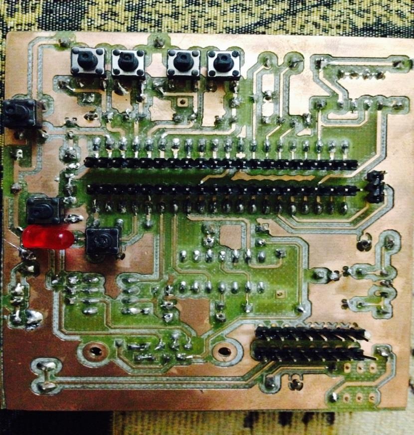
33 33 Hardware implementation Screenshoots

34 Similar systems 34 D900 Standalone OBD scanner is connected to the OBD interface on car directly and supports the five main communication protocols.
35 Limitations 35 Standards availability On-board diagnostics system has five common communication protocols, this protocols specifics the communication process between the OBD scanner and the car ECU. These protocols are ISO standards, not available for free and the average price for each protocol $. This problem has been solved after a long search for free documents that describe the required details about each protocol. Testing environment Our testing environment is cars, and for each protocol we need different type of cars, we could not find a car ECU emulator which will ease testing process, also we faced problems in finding people who will let us make our testing on their cars. Time The available period for graduation project implementation which is four months is very adequate, but unfortunately we spent two and a half months on another project (implementing home automation system through home electrical network) but we have faced many problems that forced us to change the idea so we worked on OBD Scanner project for the half of the period.
36 Standards/Codes 36 ISO :2011 Road vehicles -- Diagnostic communication over Controller Area Network (DoCAN) -- Part 4: Requirements for emissions-related systems ISO 9141:1989 Road vehicles -- Diagnostic systems -- Requirements for interchange of digital information ISO :2000 Road vehicles -- Diagnostic systems -- Keyword Protocol Part 4: Requirements for emission-related systems ISO :2011 Road vehicles -- Communication between vehicle and external equipment for emissions-related diagnostics -- Part 5: Emissions-related diagnostic services

37 37 OBD simulator
38 PLC Project 38 About A remotely controlled electrical plug system which applies functionalities like (on & off) operations, timed operations and power readings. The brilliant idea here is the communication medium, its neither WIFI nor Bluetooth which always raise the costs; the electrical signals of electricity home network are used to communicate with plugs. Technology Power line carrier communication
39 39 PLC Project-power line carrier modem

40 PLC Project - Problems 40 Printed circuit design of NCN Special circuit components availability High speed printing requirements

41 PLC Project-PLC evaluation board 41 C2000 Power Line Modem Developer's Kit ($599.00)
42 42 Thanks
Chris Frey May 3, 2013 ECET - CPET 491 Senior Design Project Phase II Project Advisor and Instructor: Professor Paul I. Lin
 Chris Frey May 3, 2013 ECET - CPET 491 Senior Design Project Phase II Project Advisor and Instructor: Professor Paul I. Lin Goals Motivation Introduction Problem Statement / Solution Project Research Overall
OBD-II Engine Code Reader with Bluetooth Technology
 User Manual OBD-II Engine Code Reader with Bluetooth Technology PP-2145 Specifications: Working environment temperature: -40 C ~ 85 C Voltage: 9-16VDC Working current: 45mA Standby current: < 40mA Wireless
OBDII J1708/J1587 Simulator
 1 Features: Support the total 8 protocols., Customer can choose any 2 protocols or any 5 protocols or all 8 protocols in different cost 1. ISO14230-4 (KWP2000) Fast Init 2. ISO14230-4 (KWP2000) Baud 5
K-line Communication Description
 K-line Communication Description Introduction There are two primary ISO documents that describe how to perform OBD communications on K- line between a tester and a vehicle. There are actually several ISO
SURFACE VEHICLE RECOMMENDED PRACTICE
 400 Commonwealth Drive, Warrendale, PA 15096-0001 SURFACE VEHICLE RECOMMENDED PRACTICE An American National Standard J1979 Issued 1991-12 Revised 1997-09 Superseding J1979 JUL96 REV. SEP97 E/E DIAGNOSTIC
USER GUIDE. incardoc Android
 USER GUIDE incardoc Android OVERVIEW Use Smartphone for Quick View of the Car and Engine Main Parameters: Read real-time parameters: speed, rotation, timings, economy Read diagnostic trouble codes Clean
Implementation and Validation of K Line (ISO 9141) Protocol for Diagnostic Application
 Protocol for Diagnostic Application") Implementation and Validation of K Line (ISO 9141) Protocol for Diagnostic Application Gauri Mahajan 1, Mr. S.K.Parchandekar 2, Mr. Mohammad Tahir 3 1,2 Department of Electronics Engineering Walchand college
Implementation and Validation of K Line (ISO 9141) Protocol for Diagnostic Application Gauri Mahajan 1, Mr. S.K.Parchandekar 2, Mr. Mohammad Tahir 3 1,2 Department of Electronics Engineering Walchand college
USING SCAN TOOL MEMORY
 Table of Contents SAFETY PRECAUTIONS SAFETY FIRST!... 1 SCAN TOOL CONTROLS CONTROLS AND INDICATORS... 3 DISPLAY FUNCTIONS... 4 BATTERY REPLACEMENT... 6 USING THE SCAN TOOL CODE RETRIEVAL PROCEDURE... 7
Microprocessor Communication Module Connecting On Board Diagnostic System and Personal Computer
 Microprocessor Communication Connecting On Board Diagnostic System and Personal Computer Nina Bencheva, Yordan Alexandrov Microprocessor Communication Connecting On Board Diagnostic System and Personal
USBCAN-OBD. USB to CAN adapter. User Manual. Document version 3.01 (2015/04/22)
") USB to CAN adapter User Manual Document version 3.01 (2015/04/22) Contents 1. Introduction... 3 1.1 Functional Overview... 3 1.2 Properties at a Glance...3 1.3 Typical application... 3 2. Installation...
USB to CAN adapter User Manual Document version 3.01 (2015/04/22) Contents 1. Introduction... 3 1.1 Functional Overview... 3 1.2 Properties at a Glance...3 1.3 Typical application... 3 2. Installation...
Automotive demonstrator hmi proposal
 Automotive demonstrator hmi proposal Outline T5.2B Demonstrator Architecture Distributed HMI View 1 (7 touch screen) View 2 (HUD) Multimodality and Proactiveness 2 Architecture GPS Mic FC LSC RSC St VISODO
mobydic 4910 Multiprotocol ECU Simulator v1.01 Features
 Features Simulates a single or 4 different ECU's ( PCM,TCM,HEC,ABS) Selectable protocol via dip switch Selectable Gasoline / Diesel PID's Advanced monitoring / Readiness functions Generates DTC for each
ISO INTERNATIONAL STANDARD
 INTERNATIONAL STANDARD ISO 15031-5 First edition 2006-01-15 Road vehicles Communication between vehicle and external equipment for emissions-related diagnostics Part 5: Emissions-related diagnostic services
SAFETY PRECAUTIONS AND WARNINGS...
 Table of Contents 1. SAFETY PRECAUTIONS AND WARNINGS... 1 2. GENERAL INFORMATION... 2 2.1 ON-BOARD DIAGNOSTICS (OBD) II... 2 2.1.1 DIAGNOSTIC TROUBLE CODES (DTCS)... 2 2.1.2 OBDII MODES OF OPERATION...
SAFETY PRECAUTIONS AND WARNINGS...
 Table of Contents 1. SAFETY PRECAUTIONS AND WARNINGS... 1 2. GENERAL INFORMATION... 2 2.1 ON-BOARD DIAGNOSTICS (OBD) II... 2 2.1.1 DIAGNOSTIC TROUBLE CODES (DTCS)... 2 2.1.2 OBDII MODES OF OPERATION...
SAFETY PRECAUTIONS AND WARNINGS...
 Table of Contents 1. SAFETY PRECAUTIONS AND WARNINGS... 1 2. GENERAL INFORMATION... 2 2.1 ON-BOARD DIAGNOSTICS (OBD) II... 2 2.2 DIAGNOSTIC TROUBLE CODES (DTCS)... 2 2.3 LOCATION OF THE DATA LINK CONNECTOR
ISO INTERNATIONAL STANDARD
 INTERNATIONAL STANDARD ISO 15031-5 First edition 2006-01-15 Road vehicles Communication between vehicle and external equipment for emissions-related diagnostics Part 5: Emissions-related diagnostic services
LDV Communications Specification
 LDV6x-0308m - 1/22 Models: LDV6S and LDV6U LDV Communications Specification 2/19/2002 Rev 0.1 Created document draft JDS 2/22/2002 Rev 0.11 Added instructions on the use of Broadcast Messages JDS 3/18/2002
Team 9 Senior Design 2011
 Table of Contents 1.0 Executive Summary... 1 2.0 Project Description... 2 2.1 Motivation and Goals... 2 2.2 Software Requirements... 2 2.2.1 Requesting and Receiving Data... 2 2.2.2 GUI Requirements...
Road vehicles Communication between vehicle and external equipment for emissions-related diagnostics
 BRITISH STANDARD BS ISO 15031-5:2006 Road vehicles Communication between vehicle and external equipment for emissions-related diagnostics Part 5: Emissions-related diagnostic services ICS 13.040.50; 43.040.10
SAFETY PRECAUTIONS AND WARNINGS...
 Table of Contents 1. SAFETY PRECAUTIONS AND WARNINGS... 1 2. GENERAL INFORMATION... 2 2.1 ON-BOARD DIAGNOSTICS (OBD) II... 2 2.2 DIAGNOSTIC TROUBLE CODES (DTCS)... 2 2.3 LOCATION OF THE DATA LINK CONNECTOR
DEVELOPMENT OF OBD-II DRIVER INFORMATION SYSTEM
 010 DEVELOPMENT OF OBD-II DRIVER INFORMATION SYSTEM I. Aris 1, M.F. Zakaria 2, S.M. Abdullah 1, R.M Sidek 1 1 Dept. of Electrical and Electronics Engineering, Universiti Putra Malaysia, 43400, Malaysia.
escan release notes: Revision History:
 escan release notes: Revision History: 04/29/2018: Rev 1.3.4: Very large update to Volumetric Efficiency baseline database. Added Volumetric Efficiency support for pressurized induction systems (please
Topic: OBDLink problems, Please Help (Read 967 times)
") 1 of 11 11/13/2012 10:28 AM Welcome, Guest. Please login or register. Did you miss your activation email? November 13, 2012, 08:24:08 AM News: Added OBDLink MX forum board. ScanTool.net Forum Hardware
1 of 11 11/13/2012 10:28 AM Welcome, Guest. Please login or register. Did you miss your activation email? November 13, 2012, 08:24:08 AM News: Added OBDLink MX forum board. ScanTool.net Forum Hardware
OBD-II Diagnostic In this guide you will learn how to use our new feature OBD-II Diagnostic. And, specifically, how to set it up and use it in repair.
 OBD-II Diagnostic In this guide you will learn how to use our new feature OBD-II Diagnostic. And, specifically, how to set it up and use it in repair. Keep in mind that the whole range of functionality
Table of Contents 1. SAFETY PRECAUTIONS AND WARNINGS GENERAL INFORMATION ON-BOARD DIAGNOSTICS (OBD) II DIAGNOSTIC TROUBLE
 II DIAGNOSTIC TROUBLE") Table of Contents 1. SAFETY PRECAUTIONS AND WARNINGS... 1 2. GENERAL INFORMATION... 2 2.1 ON-BOARD DIAGNOSTICS (OBD) II... 2 2.2 DIAGNOSTIC TROUBLE CODES (DTCS)... 2 2.3 LOCATION OF THE DATA LINK CONNECTOR
Table of Contents 1. SAFETY PRECAUTIONS AND WARNINGS... 1 2. GENERAL INFORMATION... 2 2.1 ON-BOARD DIAGNOSTICS (OBD) II... 2 2.2 DIAGNOSTIC TROUBLE CODES (DTCS)... 2 2.3 LOCATION OF THE DATA LINK CONNECTOR
iobd2 MFi BT VAG Adapter User Manual
 iobd2 MFi BT VAG Adapter User Manual VW, AUDI, SKODA, SEAT Preface Thank you for using this product. Please read instructions carefully before operating this unit. This manual guides the users how to operate
Reprogram Vehicles Using The EASE Universal Reprogrammer II+ & Your PC
 Reprogram Vehicles Using The EASE Universal Reprogrammer II+ & Your PC Do you know that many times reprogramming is the only way to repair a vehicle and eliminate false DTCs? Have you ever stopped working
ISO INTERNATIONAL STANDARD. Road vehicles Diagnostic systems Keyword Protocol 2000 Part 2: Data link layer
 INTERNATIONAL STANDARD ISO 14230-2 First edition 1999-03-15 Road vehicles Diagnostic systems Keyword Protocol 2000 Part 2: Data link layer Véhicules routiers Systèmes de diagnostic Protocole «Keyword 2000»
Owner s Manual & Safety Instructions
 Owner s Manual & Safety Instructions Save This Manual Keep this manual for the safety warnings and precautions, assembly, operating, inspection, maintenance and cleaning procedures. Write the product s
Wireless OBD II CAN Bus Embedded System Design
 Wireless OBD II CAN Bus Embedded System Design Carmen Bovalino January 2014 Table of Contents Objective... 1 Background... 1 Description of Proposal... 2 System Operation... 3 System Requirements... 3
Declaration. Xtool X100 PAD2 User Manual Instructions
 Declaration 1. This manual is designed for the usage of X100 PAD2, applying to X100 PAD2 smart automotive diagnosis platform. No part of this manual can be reproduced, stored in a retrieval system or transmitted,
SAFETY PRECAUTIONS AND WARNINGS...
 Table of Contents 1. SAFETY PRECAUTIONS AND WARNINGS... 1 2. GENERAL INFORMATION... 2 2.1 ON-BOARD DIAGNOSTICS (OBD) II... 2 2.2 DIAGNOSTIC TROUBLE CODES (DTCS)... 2 2.3 LOCATION OF THE DATA LINK CONNECTOR
Declaration. 5. is the registered trademark of SHENZHEN XTOOLTECH CO.,LTD.
 Declaration 1. This manual is designed for the usage of X100 PAD2, applying to X100 PAD2 smart automotive diagnosis platform. No part of this manual can be reproduced, stored in a retrieval system or transmitted,
OBD Auto Doctor. User Manual for ios (iphone and ipad) Copyright 2018 Creosys Ltd
 Copyright 2018 Creosys Ltd") OBD Auto Doctor User Manual for ios (iphone and ipad) Copyright 2018 Creosys Ltd User Manual for ios (iphone and ipad) 1. Introduction 1.1 Platform and Hardware Requirements 1.2 Supported Adapters 1.3
OBD Auto Doctor User Manual for ios (iphone and ipad) Copyright 2018 Creosys Ltd User Manual for ios (iphone and ipad) 1. Introduction 1.1 Platform and Hardware Requirements 1.2 Supported Adapters 1.3
Table of Contents SAFETY PRECAUTIONS AND WARNINGS... 1 GENERAL INFORMATION ON-BOARD DIAGNOSTICS (OBD) II DIAGNOSTIC TROUBLE CODES
 II DIAGNOSTIC TROUBLE CODES") Table of Contents 1. 2. SAFETY PRECAUTIONS AND WARNINGS... 1 GENERAL INFORMATION... 2 2.1 ON-BOARD DIAGNOSTICS (OBD) II... 2 2.2 DIAGNOSTIC TROUBLE CODES (DTCS)... 2 2.3 LOCATION OF THE DATA LINK CONNECTOR
Table of Contents 1. 2. SAFETY PRECAUTIONS AND WARNINGS... 1 GENERAL INFORMATION... 2 2.1 ON-BOARD DIAGNOSTICS (OBD) II... 2 2.2 DIAGNOSTIC TROUBLE CODES (DTCS)... 2 2.3 LOCATION OF THE DATA LINK CONNECTOR
Troubleshooter Quick Reference Guide
 Troubleshooter Quick Reference Guide March 2008 EAZ0025B29B Rev. C Trademarks Acknowledgement Snap-on, Scanner, and Fast-Track are trademarks of Snap-on Incorporated. All other marks are trademarks of
OE90C2600 OE90C2600 PLCC-28. mobydic 2600 plus version 1.00 released Features
 Features Compatible with EOBD/OBDII standard Communication at 900 Baud OBDII / EOBD Modes..9 ISO9 KWP000 J0 VPWM and PWM CAN Bus Multiple response from multiple ECU Physical and fonctional addressing EOBD/OBDII
SAFETY PRECAUTIONS AND WARNINGS...
 Table of Contents 1. SAFETY PRECAUTIONS AND WARNINGS... 1 2. GENERAL INFORMATION... 2 2.1 ON-BOARD DIAGNOSTICS (OBD) II... 2 2.2 DIAGNOSTIC TROUBLE CODES (DTCS)... 2 2.3 LOCATION OF THE DATA LINK CONNECTOR
OE 20 C1 OE20C VCC RxD RST LED1 LED2. TxD XTAL2 XTAL1 NC. TxK TxL. RxK GND. v /05/2004. Features
 Features Low cost Compatible with ISO & KWP000.7 to 6V operating range Direct LED drive for status display 000 baud communication Auto fast init process Auto slow init process Multiple response from multiple
SAFETY PRECAUTIONS AND WARNINGS...
 Table of Contents 1. SAFETY PRECAUTIONS AND WARNINGS... 1 2. GENERAL INFORMATION... 2 2.1 ON-BOARD DIAGNOSTICS (OBD) II... 2 2.2 DIAGNOSTIC TROUBLE CODES (DTCS)... 2 2.3 LOCATION OF THE DATA LINK CONNECTOR
Owner s Manual & Safety Instructions
 Owner s Manual & Safety Instructions Save This Manual Keep this manual for the safety warnings and precautions, assembly, operating, inspection, maintenance and cleaning procedures. Write the product s
Delphi Diagnostics DS100E user manual version 7.0 Software Version
 Delphi Diagnostics DS100E user manual version 7.0 Software Version 1.17.0 1. Summary 1 Summary 2 Copyright/Trademark 3 About the DS100E 4 Main functions of the DS100E tool 5 OBD 6 EOBD 7 Configuration
TinyOBD: A TinyOS Library for OBD-II Readers
 TinyOBD: A TinyOS Library for OBD-II Readers Gregory E. Stabler Clemson University Clemson, South Carolina gstable@clemson.edu ABSTRACT This paper presents a TinyOS library for On-board Diagnostics, Second
Designed for ios (iphone, ipad, ipod touch)
") Quick Start Guide Designed for ios (iphone, ipad, ipod touch) Table of Contents Startup Activities... 3 Using an OBD-II Wi-Fi Adapter...4 Using an OBD-II BLE Adapter... 7 Setting up Adapter IP Address
Quick Start Guide Designed for ios (iphone, ipad, ipod touch) Table of Contents Startup Activities... 3 Using an OBD-II Wi-Fi Adapter...4 Using an OBD-II BLE Adapter... 7 Setting up Adapter IP Address
IDD-213G User Manual. (Rev. 1.5)
") (Rev. 1.5) Knowledge Gate for Information Technology. September, 2014 Contents 1. Introduction... 3 2. Specifications... 4 2.1 External Interface... 4 2.2 Status Indicator... 5 2.3 Technical Parameters...
(Rev. 1.5) Knowledge Gate for Information Technology. September, 2014 Contents 1. Introduction... 3 2. Specifications... 4 2.1 External Interface... 4 2.2 Status Indicator... 5 2.3 Technical Parameters...
NC1701 ENHANCED VEHICLE COMMUNICATIONS CONTROLLER
 NC1701 ENHANCED VEHICLE COMMUNICATIONS CONTROLLER Nebula Systems has created the first dedicated controller for use in Telematics embedded systems, enabling companies in the Connected Car space to access
Advanced OBDII Data Streamer
 LDVDSV2 Data Sheet v1.03 Page 1 Model LDVDSV2 Advanced OBDII Data Streamer The B&B Electronics AutoTap OBDII Data Streamer Model LDVDSV2 connects your PC, driver terminal, Java-enabled phone, or other
TECHNICAL DATASHEET #TDAX050000K CAN
 This cost-effective, compact and robust CAN display shows machine, engine and transmission operating parameters and service codes. Enhanced operating information made available to a vehicle operator improves
AiM Infotech. Hondata KPro4. Release 1.01
 AiM Infotech Hondata KPro4 Release 1.01 1 Supported model This tutorial explains how to connect Hondata ECU to AiM devices. Supported model is: Hondata K-Pro4 to AiM devices. 2 Software setup The ECU comes
Unified Diagnostic Services Protocol Implementation in an Engine Control Unit
 Unified Diagnostic Services Protocol Implementation in an Engine Control Unit Panuwat Assawinjaipetch 1, Michael Heeg 2, Daniel Gross 2, Stefan Kowalewski 3 1 Thai-German Graduate School of Engineering
K-Line Initialization Information
 ADVANCED VEHICLE TECHNOLOGIES, Inc. AV Inc. K-Line Initialization Information 22 April 2009 There are two sections to this document. #1: Detailed information about the different initialization modes as
Foseal Car WIFI OBD2 Scanner Check Engine Diagnostic Tool. User Manual. Works with ios & Android Device
 Foseal Car WIFI OBD2 Scanner Check Engine Diagnostic Tool User Manual Works with ios & Android Device 1 Thank you for purchasing from us. Any question with our product, please send email to us, we will
Implementation and validation of SAE J1850 (VPW) protocol solution for diagnosis application
 protocol solution for diagnosis application") Implementation and validation of SAE J1850 (VPW) protocol solution for diagnosis application Pallavi Pandurang Jadhav 1, Prof. S.N.Kore 2 1Department Of Electronics Engineering, Walchand College Of Engineering,
Implementation and validation of SAE J1850 (VPW) protocol solution for diagnosis application Pallavi Pandurang Jadhav 1, Prof. S.N.Kore 2 1Department Of Electronics Engineering, Walchand College Of Engineering,
COPYRIGHT NOTICE. Visit our website at: For Technical Assistance, send us at
 COPYRIGHT NOTICE Visit our website at: www.idutex.com For Technical Assistance, send us email at support@idutex.com 1 OBDII/EOBD PLUS Code Reader USER MANUAL 2 General Notice For your own safety and the
IDD-213W User Manual. (Rev. 1.7)
") (Rev. 1.7) February, 2017 Contents 1. Introduction... 3 2. Specifications... 4 2.1 External Interface... 4 2.2 Status Indicator... 5 2.3 Technical Parameters... 6 3. Device Configuration... 8 3.1 PC Tool...
(Rev. 1.7) February, 2017 Contents 1. Introduction... 3 2. Specifications... 4 2.1 External Interface... 4 2.2 Status Indicator... 5 2.3 Technical Parameters... 6 3. Device Configuration... 8 3.1 PC Tool...
(DH/D1) Dodge Ram 2500/3500 Pick Up Truck
 Dodge Ram 2500/3500 Pick Up Truck") Dealer Service Instructions for: Emissions Recall G30 Replace Oxygen Sensor Module and Reprogram ECM October 2007 Effective immediately all repairs on involved vehicles are to be performed according to
Dealer Service Instructions for: Emissions Recall G30 Replace Oxygen Sensor Module and Reprogram ECM October 2007 Effective immediately all repairs on involved vehicles are to be performed according to
VSI-2534 User Manual
 VSI-2534 User Manual Version 2.2 April 2011 Foreword This document describes AutoEnginuity (DG) VSI-2534, and SAE J2534 Pass-Thru device with its primary purpose to program automotive ECUs (Electronic
THE StarSCAN FLASH FILES FOR THIS BULLETIN MUST BE RETRIEVED FROM THE INTERNET.
 NUMBER: 18-033-07 GROUP: Vehicle Performance DATE: May 16, 2007 This bulletin is supplied as technical information only and is not an authorization for repair. No part of this publication may be reproduced,
Heated Oxygen Sensor (HO2S )
") Page 1 of 11 Year = 2011 Model = Mustang Engine = 5.0L VIN = IDS Version = t Available Heated Oxygen Sensor (HO2S ) WARNING: Crown Victoria Police Interceptor vehicles equipped with fire suppression system,
Page 1 of 11 Year = 2011 Model = Mustang Engine = 5.0L VIN = IDS Version = t Available Heated Oxygen Sensor (HO2S ) WARNING: Crown Victoria Police Interceptor vehicles equipped with fire suppression system,
Vehicle Network Gateway (VNG)
") Vehicle Network Gateway (VNG) (With emphasis on the j1850 interface) Fetah Basic (Spencer Volmar and Marc Oliver Co-Workers) Abstract The Vehicle Network Gateway or VNG (pronounced ving ) is a small embedded
Vehicle Network Gateway (VNG) (With emphasis on the j1850 interface) Fetah Basic (Spencer Volmar and Marc Oliver Co-Workers) Abstract The Vehicle Network Gateway or VNG (pronounced ving ) is a small embedded
Automotive Diagnostic Software ScanMaster ELM. User Manual. Version 2.0. Copyright 2014 TotalCarDiagnostics.com
 Automotive Diagnostic Software ScanMaster ELM User Manual Version 2.0 2014 Copyright 2014 TotalCarDiagnostics.com Content 1. Basic Features... 3 2. Minimum Platform and Software Requirements... 4 3. What
ELM322 OBD (VPW) to RS232 Interpreter
 to RS232 Interpreter") OBD (VPW) to RS232 Interpreter Description Since the 1996 model year, North American automobiles have been required to provide an OBD, or On Board Diagnostics, port for the connection of test equipment.
OBD (VPW) to RS232 Interpreter Description Since the 1996 model year, North American automobiles have been required to provide an OBD, or On Board Diagnostics, port for the connection of test equipment.
THE StarSCAN FLASH FILES FOR THIS BULLETIN ARE AVAILABLE VIA THE INTERNET. StarSCAN SOFTWARE LEVEL MUST BE AT RELEASE 9.04 OR HIGHER.
 NUMBER: 18-001-09 GROUP: Vehicle Performance DATE: January 21, 2009 This bulletin is supplied as technical information only and is not an authorization for repair. No part of this publication may be reproduced,
IMPORTANT NOTICES... 3 SAFETY PRECAUTIONS... 4
 CONTENTS IMPORTANT NOTICES........................................ 3 SAFETY PRECAUTIONS....................................... 4 Introduction...........................................5 Datastream............................................6
Carmanscan AT User Guide
 Carmanscan AT User Guide Ver. 100501A Safety Cautions This information is to protect your safety and prevent property damage. Make sure to read it thoroughly before use. 1 Table of Contents Cautions in
SKP-900 User s Manual
 SKP-900 User s Manual 1. Introduction SuperOBD SKP-900 Key Programmer is a hand-held device for reading and programming auto transponder keys, auto remote keys, and auto smart keys. It is strong in functions,
User Manual. 1. Introduction MtrackScout OBD-II Compliant... 2
 User Manual Contents 1. Introduction... 2 1.1. MtrackScout OBD-II Compliant... 2 2. Hardware Features... 2 2.1. OBD-II Protocol... 2 2.2. Micro USB Connection... 2 2.3. Buzzer... 2 2.4. Power Supply...
DTC P0335 CKP Sensor A Circuit Performance
 2000 Cadillac DeVille DTC P0335 CKP Sensor A Circuit Performance Circuit Description The PCM uses dual crankshaft position (CKP A and CKP B) sensors to determine crankshaft position. The PCM supplies an
X-431 Volkswagen Diagnosis. Table of Contents INTRODUCTION...1
 Table of Contents INTRODUCTION...1 FEATURES...1 Advanced...1 Open...1 Integrative...1 Flexible...1 HARDWARE CONFIGURATION...2 PORTS AND INDICATORS...3 PRINTER OPERATION...4 Mounting Paper...4 Printing
Mongoose Pro Quick Start Guide
 Mongoose Pro Quick Start Guide PLEASE NOTE Mongoose Pro interfaces have been carefully designed and tested to comply with OBDII protocols. However, some vehicle models are not in full compliance with these
User Implementation Document
 OBDII STREAMER FAMILY User Implementation Document Page 1/49 Table of Contents OBDII Streamer Command & Response Table of Contents... 2 Document Revision History... 4 Communication Protocol Definition...
Command and Response Document
 OBDII STREAMER FAMILY Command and Response Document Page 1/59 Table of Contents OBDII Streamer Command & Response Table of Contents...2 Document Revision History...4 Communication Protocol Definition...7
A UNIVERSAL REMOTE CONTROLLER WITH HAPTIC INTERFACE FOR CUSTOMER ELECTRONIC DEVICES
 A UNIVERSAL REMOTE CONTROLLER WITH HAPTIC INTERFACE FOR CUSTOMER ELECTRONIC DEVICES The main aim of this project is to introduce a new universal remote control that gives easy-to-control interface for
SECONS SDI Diagnostics Interface Installation and Operation Manual
 SECONS SDI Diagnostics Interface Installation and Operation Manual ver. 1.00 Table of Contents Important installation notice...3 Safety precautions... 3 Usage guidelines...3 SDI Interface drivers installation...4
CarDAQ-M J2534-1&2 Module Quick Start Guide
 CarDAQ-M J2534-1&2 Module Quick Start Guide CarDAQ-M has been carefully designed and tested to comply with OBDII protocols, which are used on most 1996 and newer cars and light trucks sold in the USA.
MRS Electronic, Inc Winner Circle Dayton, OH (937) Datasheet CAN Relay Box 16. Page 1 of 8 Version 1.
 Datasheet CAN Relay Box 16. Page 1 of 8 Version 1.") Page 1 of 8 Version 1.4 Technical Data Housing Aluminum housing Connector PCB connection header S2C-SMT 3.50/32/90LF Housing Dimensions 109.4 x 105.8 x 34.7 mm Weight 332 g Temperature Range (ambient)
Page 1 of 8 Version 1.4 Technical Data Housing Aluminum housing Connector PCB connection header S2C-SMT 3.50/32/90LF Housing Dimensions 109.4 x 105.8 x 34.7 mm Weight 332 g Temperature Range (ambient)
EngineCheck. User manual Version January Gendan Limited
 User manual Version 3.1 January 2013 sales@enginecheck.co.uk www.enginecheck.co.uk 2013 Gendan Limited Table of contents Installation 3 Activation 3 Using 4 Connecting to a car 5 Connection problems 5
OBD GPS Tracker CW-601 User Manual
 OBD GPS Tracker CW-601 User Manual Tel: 0086-755-33633930 Fax: 0086-755-33633934 www.chainwayits.com Contents 1. PREVIEW... 2 2. DEVICE... 2 2.1 GENERAL INTRODUCTION... 2 2.2 TECHNOLOGY SPECIFICATIONS...
Either witech OR StarMOBILE DESKTOP CLIENT can be used to perform this bulletin. FLASH FILES FOR THIS BULLETIN ARE AVAILABLE VIA THE INTERNET.
 NUMBER: 18-020-10 GROUP: Vehicle Performance DATE: June 10, 2010 This bulletin is supplied as technical information only and is not an authorization for repair. No part of this publication may be reproduced,
AVT-718 SDM-AOS Support
 ADVANCED VEHICLE TECHNOLOGIES, Inc. AV Inc. AVT-718 SDM-AOS Support 4 September 2003 This document describes the so - called SDM mode of operation for the AVT-718 unit. SDM mode support was first released
After-Sales Service Technical Support Communication Letter. TB T31 Cannot erase DTC P1435 and cannot clear MIL.
 Nissan Ireland PO Box 910 Naas Road Dublin 12 Technical Bulletin REFERENCE: MODEL: After-Sales Service Technical Support Communication Letter T31 X-TRAIL SUBJECT: TB T31 Cannot erase DTC P1435 and cannot
Mongoose Pro GMII Quick Start Guide
 Mongoose Pro GMII Quick Start Guide PLEASE NOTE Mongoose Pro interfaces have been carefully designed and tested to comply with OBDII protocols. However, some vehicle models are not in full compliance with
Used Delightedly, User-Friendly MARUTI,MAZDA,MITSUBISHI,NISSAN,SUBARU,SUZUKI,TOYOTA, TATA, CHRYSLER, 8
 Shor tcut keys Including CR501/601/611/801/811/821/910/920/981 DTC One-click Reading DTCs ER One-click Clearing DTCs I/M One-click Reading IM Readiness Statu? Tips and Help Car Model Suppor ting (46) Automotive
C Mon diagnostic tool quicktour C mon description and features
 C Mon diagnostic tool quicktour C mon description and features 12 13 14 6 11 10 9 7 8 1 4 2 1 - Button #1 2 - Button #2 3 - Button #3 4 - Button #4 5 - Power switch 6 - LCD screen 7 - Busy led 8 - Power
Audi, Seat, Skoda and Volkswagen
 Seat, Skoda and Volkswagen Audi, Seat, Skoda and Volkswagen ECU Version (VAG Mode 1) Selecting 'ECU Version' displays the following data for the selected control module: Part Number System Name Version
Table of Contents 1 GETTING STARTED... 3
 Table of Contents 1 GETTING STARTED... 3 1.1 TOOL DESCRIPTIONS... 3 1.2 ACCESSORY INCLUDED... 4 1.3 SPECIFICATIONS... 4 1.4 PREPARATION &CONNECTIONS... 4 1.4.1 Preparation... 4 1.4.2 Connecting to Vehicle...
Design & Implementation of CAN Bus for Intelligent Vehicle using Sensors System
 IJIRST International Journal for Innovative Research in Science & Technology Volume 2 Issue 11 April 2016 ISSN (online): 2349-6010 Design & Implementation of CAN Bus for Intelligent Vehicle using Sensors
CONTROLLER AREA NETWORK (CAN)
") GROUP 54C CONTROLLER AREA NETWORK (CAN) CONTENTS GENERAL INFORMATION........ 54C-2 STRUCTURE................... 54C-3 SELF-DIAGNOSIS............... 54C-6 CAN BUS DIAGNOSTICS......... 54C-6 OPERATION...................
GROUP 54C CONTROLLER AREA NETWORK (CAN) CONTENTS GENERAL INFORMATION........ 54C-2 STRUCTURE................... 54C-3 SELF-DIAGNOSIS............... 54C-6 CAN BUS DIAGNOSTICS......... 54C-6 OPERATION...................
Data Acquisition Instructions
 Page 1 of 26 Form DAQ2_A 01/23/2007 Superchips Inc. Superchips flashpaq Data Acquisition Instructions Visit Flashpaq.com for downloadable updates & upgrades to your existing tuner. Page 2 of 26 Form DAQ2_A
ISO INTERNATIONAL STANDARD. vehicles Diagnostics on. systems. routiers Diagnostic sur gestionnaire de réseau de communication
 INTERNATIONAL STANDARD vehicles Diagnostics on Road Area Networks (CAN) Controller 4: Part for emissions-related Requirements routiers Diagnostic sur gestionnaire de réseau de Véhicules (CAN) communication
AVT-718. Multiple Interface. RS-232 or RS-422 Unit
 ADVANCED VEHICLE TECHNOLOGIES, Inc. AV inc. AVT-718 Multiple Interface RS-232 or RS-422 Unit User s Manual 1509 Manor View Road Davidsonville, MD 21035 410-798-4038 (voice) 410-798-4308 (fax) www.avt-hq.com
Fleet Management - Smart, Secure and Easy
 Fleet Management - Smart, Secure and Easy Automile is a comprehensive fleet management solution to monitor both company and service vehicles and provide rich insights. Our hardware requires no installation
Introduction of Au SAE J1939 Simulator Gen II 1.00A and 2.00A
 Introduction of Au SAE J1939 Simulator Gen II 1.00A and 2.00A Au SAE J1939 Simulator Gen II (Figure 1), a family of well designed devices, is capable of simulating majority of SAE J1939 signals on a SAE
Procedure revision date: 03/19/2013
 2010 Explorer 2010 PCED Gasoline Engines SECTION 5: Pinpoint Tests Report a problem with this article Procedure revision date: 03/19/2013 KD: Electric Exhaust Gas Recirculation (EEGR) System KD: Introduction
To be familiar with the USART (RS-232) protocol. To be familiar with one type of internal storage system in PIC (EEPROM).
 protocol. To be familiar with one type of internal storage system in PIC (EEPROM).") Lab # 6 Serial communications & EEPROM Objectives To be familiar with the USART (RS-232) protocol. To be familiar with one type of internal storage system in PIC (EEPROM). Serial Communications Serial
Lab # 6 Serial communications & EEPROM Objectives To be familiar with the USART (RS-232) protocol. To be familiar with one type of internal storage system in PIC (EEPROM). Serial Communications Serial
Road vehicles Communication between vehicle and external equipment for emissions-related diagnostics. Part 5: Emissions-related diagnostic services
 INTERNATIONAL STANDARD 15031-5 This is a preview of " 15031-5:2015". Click here to purchase the full version from the ANSI store. Third edition 2015-08-01 Road vehicles Communication between vehicle and
Service Technical Resources MUT-III. (Multi-Use Tester-III*) Quick Reference Guide
 Quick Reference Guide") Service Technical Resources MUT-III (Multi-Use Tester-III*) Quick Reference Guide *Cart not included May, 2003 INTENDED USAGE OF MUT-III MUT-II role after MUT-III Launch MUT-III is an essential special
Service Technical Resources MUT-III (Multi-Use Tester-III*) Quick Reference Guide *Cart not included May, 2003 INTENDED USAGE OF MUT-III MUT-II role after MUT-III Launch MUT-III is an essential special
ecuexplorer User Guide
 Installation...2 Getting Started...3 User Interface...3 Menu Structure...3 Initial Configuration...5 Hotkeys...6 Navigation Tree...7 User-Defined Data Items...7 Known Trouble Codes...8 Saved Log Files...9