NORGES TEKNISK-NATURVITENSKAPELIGE UNIVERSITET FAKULTET FOR INFORMASJONSTEKNOLOGI, MATEMATIKK OG ELEKTROTEKNIKK. Hovedoppgave
|
|
|
- Abigayle White
- 6 years ago
- Views:
Transcription
1 NORGES TEKNISK-NATURVITENSKAPELIGE UNIVERSITET FAKULTET FOR INFORMASJONSTEKNOLOGI, MATEMATIKK OG ELEKTROTEKNIKK Hovedoppgave Kandidatens navn: Fag: Oppgavens tittel (norsk): Tor Einar Lyngset, Tom Vasset SIF80/HO2 MDA (Model Driven Architecture) Oppgavens tittel (engelsk): MDA (Model Driven Architecture) Oppgavens tekst: MDA is coined by OMG as the next big step in application integration. MDA, when realized, allows application developers to completely decouple business modeling (such as UML models) from platform-dependent implementations of applications (such as implementations in J2EE, Web services, Parlay). This separation is made possible by formal semantics defined in Meta Object Facility (MOF). MOF enables interoperability and automatic transformation of models. MOF is the metamodel used to express UML and a number of other OMG standards. See for more details on MDA. Telenor R&D is involved in an IST project ( where we aim to employ MDA as a means to increase interoperability among telecommunication applications, and to increase reuse in telecommunication application development. The candidates will participate in the project and perform implementation, testing and experimentation with MDA-enabled tools and MDA-based applications. Oppgaven gitt: 20. januar 2003 Besvarelsen leveres innen: 16. juni 2003 Besvarelsen levert: 30. mai 2003 Utført ved: IDI, NTNU / Telenor FoU Veileder: Babak Farshchian Trondheim, Monica Divitini Faglærer
2 Abstract This master thesis investigates the Object Management Group s (OMG) Model Driven Architecture (MDA) and tool supported MDA development. The basis for this investigation is: A literature study of the MDA, focusing on MDA development and tool support. A MDA development tool survey, investigating current MDA development tools and their features. An MDA development case study, experimenting with three of these MDA development tools: Interactive Object s ArcStyler, Compuware s OptimalJ and Objecteering s Objecteering/UML. MDA is proposed by the OMG as the next big step in solving system integration and interoperability problems. The success of the MDA will largely depend on the quality of the tools supporting MDA development. From our tool survey and case study experimentation, we found that these tools still have far to go before they fulfill the promised benefits of the MDA. Support for important concepts such as platform independent modeling, model transformations, legacy integration and artifact/code generation needs to improve before these tools can reach their true potential. MDA has at the time of writing no clear specification and it is also based on specifications that have not yet been adopted, most notably the UML 2.0 specification. As the OMG s specification work proceeds and the tool vendors start to implement these specifications, especially the platform independent/platform specific UML profile specifications, we believe that we will see a new generation of MDA development tools that will seriously contend with state-of-the-art traditional (non-mda) development tools. 2
3 Preface This master thesis was worked out at the Norwegian University of Technology and Science (NTNU), Department of Computer and Information Science (IDI) in the period January to June The background for this work is Telenor R&D s involvement in the IST MODA-TEL project on Model Driven Architecture (MDA) for the telecommunications domain. Our participation in Telenor s work on this subject is to a look at MDA and experiment with some of the development tools available that supports this technology. We want to thank our two supervisors Babak Farshchian at Telenor and Professor Monica Divitini at NTNU, and Sune Jakobsson at Telenor, for valuable feedback and support during the thesis work. We also want to thank the tool vendors we have been in contact with during these months, especially Pascale Perrot and Patrick Saint-Andre at Objecteering, and Giovanni Faggioli at IO-Software for their participation and valuable support. Trondheim 30. mai 2003, Tor Einar Lyngset Tom Vasset 3
4 Table of Contents 1 Introduction Motivation Model Driven Architecture Work context Work description and objectives Work approach Work contribution Report structure Model Driven Architecture (MDA) Introducing the MDA MDA development MDA development tool support MDA development tool survey Objectives and approach Available tools Results of the survey Tool selection Introducing the selected MDA development tools Introducing ArcStyler Introducing OptimalJ Introducing Objecteering/UML Case study description Case study objectives and approach Case study details Case study development Legacy development Developing with ArcStyler Developing with OptimalJ Developing with Objecteering/UML Comparing ArcStyler, Objecteering/UML and OptimalJ Discussion and result analysis Tool survey Case study The next generation of MDA development tools Conclusion and further work Conclusion and summary Evaluation of contribution Further work References Appendix Appendix A: Model Driven Architecture (MDA), concepts and technologies
5 List of figures Figure 2-1: Model Driven Architecture Figure 2-2: The MDA development lifecycle Figure 2-3: MDA development [7] Figure 2-4: Mapping to several servers and clients [7] Figure 2-5: MDA development and application states Figure 5-1: ArcStyler overall architecture [10] Figure 5-2: CRC card business modeling [11] Figure 5-3: Scenario modeling [11] Figure 5-4: Refining a business model in the Pattern Refinement Assistant [11] Figure 5-5: UML Refinement Assistant console [11] Figure 5-6: Development Steps and components in OptimalJ Figure 5-7: OptimalJ's domain class editor Figure 5-8: OptimalJ web application model Figure 5-9: OptimalJ source code editor Figure 5-10: Objecteering/UML components Figure 5-11: Objecteering/UML class diagram editor Figure 5-12: Objecteering module selection window Figure 5-13: Objecteering code generation for Java Figure 6-1: The legacy customer administration system architecture Figure 6-2: J2EE customer web portal architecture Figure 6-3:.NET customer web portal architecture Figure 6-4: Waterfall development process Figure 7-1: Customer administration system, database model Figure 7-2: Customer administration system model Figure 7-3: Customer administration system, service information Figure 7-4: Customer administration system, customer information Figure 7-5: Reverse engineered legacy model Figure 7-6: EJB model Figure 7-7: Web application class diagram Figure 7-8: Activity diagram of the Workspace Accessor Figure 7-9: The Login accessor activity diagram Figure 7-10: MDA security with ArcStyler [19] Figure 7-11: EJB security class diagram Figure 7-12: Code customization in JBuilder Figure 7-13: ArcStyler generated web application Figure 7-14: OptimalJ DBMS application model Figure 7-15: OptimalJ domain model Figure 7-16: OptimalJ EJB application model Figure 7-17: OptimalJ Web application model Figure 7-18: OptimalJ Struts implementation Figure 7-19: OptimalJ generated web application, main menu Figure 7-20: OptimalJ generated web application, customer profile Figure 7-21: OptimalJ generated web application, update customer profile Figure 7-22: Objecteering/UML PIM Figure 7-23: Objecteering PIM, customer and subscription subset Figure 7-24: Objecteering/UML EJB PSM Figure 7-25: WebLogic specific database properties Figure 7-26: WebLogic specific EJB properties
6 Figure 10-1: Model Driven Architecture Figure 10-2: Zooming on objects [2] Figure 10-3: Zooming on interactions [2] Figure 10-4: Three different levels of abstraction [2] Figure 10-5: Mapping from PIM to PSM [2] Figure 10-6: A CORBA stereotype [2] Figure 10-7: Notes in UML [2] Figure 10-8: Viewpoint correspondence [2] Figure 10-9: Refinement relation [2] Figure 10-10: Software Development Lifecycle
7 List of tables Table 1-1: Work objectives and research question Table 1-2: Work phases and work description summary Table 1-3: Contributions Table 2-1: MDA development tool features Table 3-1: MDA development tools Table 3-2: MDA development tool survey, modeling and model transformations Table 3-3: MDA development tool survey, modeling and model transformations (cont.) Table 3-4: MDA development tool survey, artifact/code generation Table 3-5: MDA development tool survey, integration with legacy applications Table 3-6: MDA development tool survey, open architecture Table 3-7: MDA tool classification attributes Table 3-8: MDA development tool survey, technology feature Table 3-9: MDA development tool survey, technology features (cont.) Table 6-1: Case study investigation attributes Table 6-2: Case study work description Table 7-1: ArcStyler MDA development investigation, summary Table 7-2: OptimalJ MDA development investigation, summary Table 7-3: Objecteering MDA development investigation, summary Table 8-1: MDA Tool classification Table 8-2: MDA development tool survey, summary of key findings Table 8-3: MDA development supported by current tools, strengths and weaknesses Table 8-4: Areas of improvement for the future MDA development tools
8 Abbreviations AS CRC CWM DBMS EAR EDOC EJB EJB-QL EURESCOM GUI HTML HUTN IDE IST JAR JCA J2EE JDBC JSP MDA MODA-TEL MOF OCL OMG PIM PSM RUP UUID UML WAR XMI XML XP ArcStyler Class Responsibility Collaboration Common Warehouse Model DataBase Management System Enterprise ARchive Enterprise Distributed Object Computing Specification Enterprise Java Beans EJB-Query Language European Institute for Research and Strategic Studies in Telecommunications Graphical User Interface Hyper Text Mark-up Language Human-Usable Textual Notation Integrated Development Environment Information Society Technologies Java ARchive J2EE Connector Architecture Java 2 Enterprise Edition Java DataBase Connectivity Java Server Page Model Driven Architecture Model Driven Architectures for Telecommunications System Development and Operation Meta Object Facility Object Constraint Language Object Management Group Platform Independent Model Platform Specific Model Rational Unified Process Universally Unique Identifier Unified Modeling Language Web ARchive XML Metadata Interchange extensible Markup Language extreme Programming 8
9 1 Introduction This introduction sets the stage for the thesis, describing the motivation, introducing the key technology, followed by the work context, objectives, approach, and contribution, ending with the report structure. 1.1 Motivation Market situation in telecommunication is changing rapidly due to the convergence of Internet and telephony networks and the removal of monopoly situations in many countries. This change poses great challenges and opportunities for telecommunication operators and service providers. One such challenge has been the increased competition in providing advanced value-added services to the customers. The abandoning of monopolist market models has brought with it a pressure on incumbent carriers, to make available their network resources to be used by third-party service and application providers. This creates a specialization of the telecommunication application development business that again puts pressure on both network operators and third-party application providers to optimize their development processes [1]. Value-added services and applications in convergent networks increasingly contain a large software part, opposed to traditional telecommunication services where software played a more modest role. Application developers resort to (often complex) software solutions for accessing and deploying network resources offered by network operators. Software is also used in order to create innovative applications that make use of a mixture of network resources (e.g. applications operating transparently on both Internet and telephony networks and utilizing corporate databases). Increased competition and the innovative nature of convergent networks make it necessary to deploy development processes that allow for rapid application development so that developers can experiment with different application types without binding too much resources. Issues that have been of central importance for the software engineering community, such as reuse and object-oriented software development are becoming more and more important also in the telecommunication domain [1]. The situation in telecommunications software development today is that applications have to be redeveloped for each new proprietary platform they are deployed on. Needless to say, this is a highly ineffective way to develop applications. Another issue is that third party service and application providers don t have a single uniform interface to develop towards, which makes the integration of an application time-consuming and costly. A method for software development that provides the means to ensure application integration, portability and interoperability would prove very beneficial. A solution for handling such issues has been proposed by the Object Management Group s with their Model Driven Architecture (MDA) initiative. 9
10 1.2 Model Driven Architecture Model Driven Architecture (MDA) [2] is proposed by the Object Management Group (OMG) for solving system integration and interoperability problems. In the face of heterogeneous and evolving technology, MDA is supposed to ensure: Portability Interoperability Increased application reuse Reduced development time Improved application quality MDA, when realized, allows application developers to completely decouple business modeling (such as UML models) from platform-dependent implementations of applications (such as implementations in J2EE,.NET, Web Services etc.). This separation is achieved by designing applications initially in platform independent models (PIMs) that contain no platform or technology specific information. By applying specific technology or domain profiles, these PIMs can be mapped or transformed (automatically, if tool supported) into platform specific models (PSMs). These PSMs are in turn the blue print for artifact/code generation (again automatically, if tool supported) and application deployment. 1.3 Work context Telenor Research & Development is involved in an IST project that is investigating MDA for the telecommunication domain: IST MODA-TEL [4] is a joint effort of European stakeholders with business interest in component architectures, to develop a sound methodology and tools to support the application of MDA in the telecommunication domain. Our work on MDA started with a 5th year masters project [27], with the same title as this thesis, in the fall of The project looked at MDA in general and at ArcStyler, a development tool supporting MDA. This master thesis follows up our project work on MDA and is, as was the former project, a part of Telenor s involvement in IST MODA-TEL. 10
11 1.4 Work description and objectives As mentioned previously, this thesis follows up our project work on MDA in the autumn of This project looked at MDA in general, describing its core technologies and concepts, followed by a case study experimentation using the ArcStyler MDA development tool. Our work here found that the MDA is a powerful concept that can solve many of the challenges the software industry faces, e.g. with regards to interoperability, portability, code and model reuse, and software quality. The work also concluded that tool support for the technology at the time seemed immature, but with only one tool as a basis for the investigation, we feel that the foundations for this conclusion was too narrow. With this in mind and the fact that there is currently little literature and work done on MDA development and MDA development tool support, we decided to investigate MDA development and the current state-of-the-art MDA development tools 1. The main objective with the work presented here will be as follows: Provide a thorough investigation of MDA development and MDA development tool support, by experimenting with and investigating the current state-of-the-art MDA development tools. This main objective is divided into more detailed objectives presented in table 1-1, together with their rationale and what research questions they address: Objectives Rationale Research questions 1. As a starting point for our work we need to What do we mean by MDA Provide an overview of clarify what we mean by MDA development and development? MDA development MDA development tool support. How can tools support this and MDA MDA development? development tool support. 2. Propose a framework or a set of requirements/features to evaluate/discuss the MDA development tools. 3. Provide an overview of the MDA development tools currently available. As there is currently no clear specification of the MDA, MDA development and MDA development tool support, we need a framework or set of features to be able to evaluate/discuss these MDA development tools. The OMG has a list of companies committed to the MDA initiative, but we have found no other sources of information regarding current available MDA development tools. We intend to provide a more complete list of the vendors and tools that (claim to) support the MDA. What key features should tools supporting MDA development have? Which MDA development tools are currently available? 4. From our second objective, we have a What technologies do these 1 By MDA development tools, we mean software development tools that in some way support (or claim to support) MDA development. Sample features for these tools are UML modelling and artefact/code generation support. 11
12 Discuss the MDA development tools found. Find common characteristics and classify them. 5. Provide a MDA development case study that constitutes a comprehensive investigation of some of the MDA development tools found. framework to discuss and compare the tools found. This discussion will enable us to characterize and classify this first generation of MDA development tools, what technologies and features they support, and to point out areas they need to improve to harvest the benefits the MDA promise (in theory). As mentioned before we experimented with MDA development in our previous work on MDA. Here we found that there are several articles describing the MDA (the OMG presentations and papers is a good place to start [5]), but there is very little information to be found on MDA development. We want to follow up our previous work on MDA development. This time around we want to experiment with a relevant set of MDA development tools, focusing especially on the core MDA concepts. The main reasons for this is that we want to describe these tools by how they support the MDA, compare them to be able infer common characteristics about them, and have a solid foundation for discussing and analyzing tool supported MDA development. tools support? What MDA concepts and other development tool features are supported? Do they have any common characteristics that classify them? How does MDA development work in practice with the current state-of-the-art MDA tools? How do the selected tools support important MDA concepts? How can these tools improve and what can (or should) be expected of the next generation of MDA development tools? What are the main challenges for these tools to harvest the benefits the MDA promise in theory? What strengths and weaknesses does MDA development with the current tools have? Table 1-1: Work objectives and research question 12
13 1.5 Work approach The work will proceed in five phases: preparation, MDA development tool survey, introduction to the selected tools, case study and discussion and analysis, as illustrated in figure 1-1. Problem, objectives, work approach Chapter 2 Chapter 3 Preparation MDA development tool survey Survey data Chapter 8 Discussion and analysis MDA development tool features Introducing the selected tools Chapter 4 Tool selection Introduction to the selected tools Case study Chapter 5,6,7 Case study data Figure 1-1: Work phases Preparation The preparation phase will primarily be a literature study of the MDA, focusing on the first two objectives described in table 1-1: MDA development and MDA development tool support. A survey of the MDA, its technologies and core concepts, was done in our previous work on MDA [27]. The literature study of MDA development is largely based on the foundation of this work which can be found in Appendix A. The main deliverable of this phase will be a set of important development tool requirements for tool supported MDA development. These features will be the input to the following MDA development tool survey MDA development tool survey To describe and investigate the current MDA development tools, we have decided to do a MDA development tool survey. This phase will address the 3 rd and 4 th objectives described in table 1-1. The work will proceed as follows: 1. Find and make a list of the currently available MDA development tools. As there is no formal specification of MDA development tool support, by the term current available MDA development tools we mean development tools that in some way claim support for the MDA. The main source of information will be the Internet. 2. Propose a set of tool investigation features to be used in the survey. These will be based on the OMG definition of MDA, a MODA-TEL delivery on MDA [4], and on our own experience with MDA development during our previous project on the MDA 13
14 [27]. The core features will be input from the preparation phase and will be complemented by a set of non-mda features we find interesting to investigate. 3. Collect data from the MDA development tool vendors, describing these tools based on the MDA development tool features. The information will be gathered by browsing product brochures on the Internet and through questionnaires sent to the vendors. 4. The MDA development tool survey will conclude with a selection of MDA development tools for further experimentation. The deliverables from this tool survey will be the survey data used for the discussion and analysis, and a set of selected MDA development tools for our case study Introducing the selected tools To get to know the selected MDA development tools, we will provide a brief introduction in this phase. This will be both a preparation to the case study investigation and a point of reference for readers that are unfamiliar with these tools. The work described here will be a literature study of each of the selected tools and behind the scenes we will acquire/download evaluation versions and prepare the following case study Case study The case study will experiment with the MDA development tools selected in the tool survey. This phase will address the second objective described in table 1.1: Provide an overview of MDA development and a comprehensive investigation of some of the MDA tools found. The work will proceed as follows: 1. For starters we will suggest a case study procedure that captures as many of the MDA concepts as possible, covering most (obviously restricted by the time limits of our work) of the application life cycle. The case study will be described both in general and specifically for our investigation. 2. Develop our case study system with the selected MDA development tools. The focus for this development will be on the core MDA concepts, e.g. PIM, PSM, model transformations etc. The development process will also be described in detail for each tool. 3. Compare the case study tools, as before focusing on the core MDA concepts. The deliverable for this phase will be the case study data that describe how the tools support the core MDA concepts. 14
15 1.5.5 Discussion and analysis This phase will discuss and analyze both the MDA development tool survey and the case study/experimentation with MDA development. The tool survey analysis will focus on the tool feature data collected in the MDA development tool survey. The case study discussion and analysis will focus on strengths and weaknesses found with current tool supported MDA development. The discussion and analysis phase will conclude with what can/should be expected of the next generation of MDA development tools. The focus will be on how and in which areas these tools can improve. Table 1-2 summarizes our work approach. Phase Objectives Work Deliverables Preparation 1, 2 Do a literature survey of MDA, focusing on MDA development and MDA development tool support. MDA development tool features MDA development tool survey Introducing the selected tools 3,4 1. Find and make a list of the currently available MDA development tools. The main source of information will be the Internet. 2. Propose a set of tool investigation features for the survey 3. Collect data from the MDA development tool vendors. 4. Select MDA development tools for further experimentation. 4 Provide a brief introduction of the selected MDA development tools and acquire/download evaluation versions for our investigation. Selection of tools Tool feature data Introduction to the selected MDA development tools Case study 5 1. Propose a case study procedure, described both in general and specifically for our investigation. Case study data 2. Develop our case study system with the selected MDA development tools. 3. Compare the tools we experimented with. Discussion and analysis Analyze and discuss the MDA development tool survey and the case study. Table 1-2: Work phases and work description summary Discussion and analysis 15
16 1.6 Work contribution The main objective of this thesis was to provide a thorough investigation of MDA development and MDA development tool support, by experimenting with and investigating the current state-of-the-art MDA development tools. Our contributions to reach this objective consist of the following: 1. A literature study of MDA development and MDA development tool support. This literature survey defines what we mean by MDA development and MDA development tool support. It was primarily based on the OMG definition of MDA [2] and John Siegel and the OMG Staff Strategy Group s Developing in OMG s Model Driven Architecture [7]. 2. A set of features for describing and comparing MDA development tools. After having defined MDA development and areas of MDA development tool support, we developed a framework, or a set of MDA development features for describing and comparing MDA development tools. 3. A survey of the existing MDA development tools. A listing of all the tools found that claim support for the MDA. A detailed description of these MDA development tools, based on the feature set from 2. The survey of the existing MDA development tools began by searching for MDA development tool on the Internet, a major source being the OMG s list of committed products [9]. When there were no more tools found, we collected tool feature data from product web sites, tutorials and by contacting the vendors, based on the feature set proposed in 2. This MDA development tool survey ended in a selection of three MDA development tools (ArcStyler, OptimalJ, and Objecteering/UML) for further in-depth experimentation. 4. An in-depth investigation (case study) of the three selected MDA development tools focusing on their implementation of the core MDA concepts. The case study was designed to describe how the different MDA tools implement our proposed set of core MDA concepts. We developed the case study system as a whole with each of the selected tools, focusing on these core MDA concepts. The investigation concludes with a comparison of the development work done with the different tools. 5. A discussion and analysis of the results obtained from the MDA development tools survey and case study, with a classification of the current MDA development tools. From the results of the MDA development tools survey we were able to classify the different kinds of tools into three classes. An analysis of the results was conducted to show how well the MDA development tools met the feature requirements set we had provided. 16
17 From the case study a discussion and analysis was provided related to the strengths and weaknesses found in 4. This enabled us to tell how well the tools supported the core MDA concepts and to compare them. 6. Suggested areas of improvement for future MDA development tools. Based on discussion and analysis we suggested areas that need to be improved for these MDA development tools to reach their true potential. Table 1-3 summarizes these contributions: Contributions 1. A literature study of MDA development and MDA development tool support 2. A set of features for describing and comparing MDA development tools 3. A survey of the existing MDA development tools. 4. An in-depth investigation (case study) of three selected MDA development tools (ArcStyler, OptimalJ and Objecteering/UML) focusing on their implementation of the core MDA concepts. 5. A discussion and analysis of the results obtained from the MDA development tools survey and case study. 6. Suggested areas of improvement for future MDA development tools. Readers guide Chapter 2 (2.1, 2.2) Section 2.3 (summarized in table 2-1). Chapter 3 (table 3-1 through 3-9). Chapter 6 (summarized in tables 6-1 through 6-3). Section 7.1 and 7.2 (tables 7-1 through 7-3). 7.3 (summarized in table 7-4). Table 1-3: Contributions 17
18 1.7 Report structure The report is structured as follows: 1. Introduction sets the stage for the thesis, describing the motivation, introducing the technology and work description, objectives, approach and contribution. 2. MDA provides a brief introduction to the Model Driven Architecture, focusing on MDA development and MDA development tool support. 3. MDA development tool survey looks at the current state-of-the-art MDA development tools, focusing on which tools are available and what features they have. The chapter concludes with a selection of three tools for the case study experimentation. 4. Introducing the selected MDA development tools provides a brief introduction to the MDA development tool used in our case study. 5. Case Study description describes the MDA development case study, proposing a development case procedure for investigating these tools both in general and specifically for our selected case. 6. Case study development describes our case study development, focusing on the MDA development tools selected and their implementation of the core MDA concepts. 7. Discussion and result analysis discuss and analyze both the MDA development tool survey and our experience with the case study. 8. Conclusion and further work concludes and summarizes the thesis work, followed by an evaluation of the contribution and pointers to future work on the subject. 9. References 10. Appendix provides more background about the concepts and technologies behind the MDA (Appendix A). 18
19 2 Model Driven Architecture (MDA) This chapter introduces the Model Driven Architecture (2.1) and provides a detailed description of MDA development (2.2) and MDA development tool support (2.3). 2.1 Introducing the MDA Model Driven Architecture as defined by the Object Management Group is a new strategy for designing software systems. MDA is not a completely new architecture, but is built on well known standards like Meta-Object Facility, Unified Modeling Language and Common Warehouse Metamodel. One of the main goals for the MDA is to continue to allow the coexistence of different types of implementation technologies and standards, while simultaneously provide a clean separation of the different layers of abstraction. The vision behind MDA, and subsequently MDA itself, addresses the whole lifecycle of a program: From business modeling to system design, to component construction, to assembly, integration, deployment, management and evolution. Figure 2-1: Model Driven Architecture To better integrate both new and old standards, MDA 1. Embraces technologies like JAVA, CORBA, XMI/XML,.NET. 2. Offers improved portability by making the first part of the design process platform independent. The design is later realized on multiple platforms by auxiliary mapping, or mapped to a specific platform by point mapping. This can either be done automatically by a mapping tool, or manually by a given mapping standard. 3. Broadens the usability of standards by improving the integration based on models of relationships across different domain applications. 19
20 Model-driven development is the notion that systems can be developed by constructing abstract views of systems and by transforming the resulting models, either automatically or manually, into code. This approach can confer increased productivity and reduced time-tomarket by enabling work at a higher level of abstraction and improving communication with non-software domain experts [28]. Since the transformation from model-to-model and modelto-code will be based on a set of defined transformation rules, the resulting applications will also be less error prone due to best practice implementation. Models, which at low levels are independent of specific technologies, are also easier to reuse than implemented code and may also solve interoperability problems otherwise encountered in traditional software development. For more details on the MDA, please refer to Appendix A. 20
21 2.2 MDA development Software development in an MDA context covers the whole lifecycle (figure 2-2) of an application; from PIM UML model, including business modeling, via PSM UML model(s), to implementation, testing, deployment, management and evolution. Because the whole lifecycle is integrated into the MDA standard, some development issues differ substantially from traditional software development. New and existing software development concepts have been applied together to make this integration possible. Base PIM PIM PSM Implementation Testing Deployment Management & Evolution Figure 2-2: The MDA development lifecycle Platform independent development All MDA development projects start with the creation of a platform independent model expressed in UML. An MDA model will have multiple levels of PIMs. Although all are independent of any particular platform, each except the base model (business model) includes platform-independent aspects of technological behavior. The PIM is refined from one level to another, gaining more information and getting closer to an actual implementation on the way. The base PIM expresses only business functionality and behavior. Built by business and modeling experts working together, this model expresses business rules and functionality undistorted, as much as possible, by technology. This modeling environment allows business experts to concentrate on the business functionality rather then technological aspects, and it becomes easier to ensure that the base PIM is complete and correct. Because this model is technologically independent it keeps its value until business conditions change. PIMs at the next level include some aspects of technology even though platform-specific details are absent. Concepts like specification of activation patterns, persistence, transactionality, security level and even configuration information enables the second-level PIM to map more precisely to a platform specific model. To incorporate this behavior into a PIM model, OCL (Object Constraint Language), which is a part of UML, is used. OCL allows the designers to specify pre- and post-conditions very precisely. Additional support for this, as well as support for Human-Usable Textual Notation (HUTN), will be provided with the release of UML 2.0. But still, some behavior of an application may not be practical to include in the model, and will have to be hand-coded in the implementation stage. MDA development tools will contain representations of Pervasive Services and Domain Facilities, see figure 2-3. This allows them to incorporate any services and facilities defined in UML into the application at the model level. In addition to encourage reuse, this feature helps ensure that invocations of pre-defined facilities are coded and executed correctly. If a service or facility runs on another middleware platform, the MDA development tool will generate cross-platform invocations automatically. 21
22 2.2.2 Platform specific development Once the first PIM refinement is complete, the model information is stored in the MOF, and the model is mapped to one or several PSMs, as shown in figure 2-4. This mapping is done using the appropriate UML profile for the intended platform. To produce a PSM, the target platform or platforms have to be selected for the modules of the application. Different modules of the model can run on different component platforms within the same application. Some of this information may already be integrated in various Pervasive Services or Domain Facilities. During the mapping step, the run-time characteristics and configuration information designed into the PIM model in a general way are converted to specific forms required by the target middleware platform, partly automated, partly hand-coded. More automation in this step is expected as profiles and mappings mature over time. Pervasive Services Model Calls PIM UML Model Calls Domain Facilities Model Mapping Stores In PSM UML Model Stores In MOF Produces Source Code Config Files WSDL UDDI DTDs SOAP XSLT... Compile, Configure, Assemble Application Server Deploy, Run Figure 2-3: MDA development [7] Starting with concepts as general as classes and interfaces, and working down to specifics of instance activation and transactional behavior, the mapping/refinement must be detailed enough to eventually enable hands-off generation of running from the PSM UML model. The core MDA modeling environment was designed to support multiple platforms, and gives the developer the opportunity to map one single PIM into several platform specific models, as 22
23 shown in figure 2-4. These models do not necessarily have to represent some kind of application server. By adding various client platforms characteristics, the MDA can be made to generate code for these targets as well. These characteristics can be embedded in profiles for such clients. This ability is the key to the MDA s utility. Figure 2-4 shows how a platform independent application UML model in the first two steps is mapped to three different servers and two client models. The next two steps show how code is generated and how the applications are compiled, configured and assembled. Even more significant is the contribution the target independence of the model makes to interoperability: Because the invoked Pervasive Services, Domain Facilities, and other enterprise applications are included in the MDA environment when the original application model is created, the MDA system is not only able to code invocations of each Service or Facility automatically it is able to go beyond simple invocation and generate each in the format of its run-time middleware platform. So among all of an enterprise s MDA applications, seamless interoperability is nearly automatic Code generation and compilation As figure 2-3 shows, a goal of future MDA development tools is to be able to generate all of the files a platform requires. The target application server has to be selected, and in case it supports multiple programming languages, this will also have to be specified. The MDA development tool will generate source code running on the specified application server in the chosen programming language. In addition to this, the tool will generate files that tell the application server how to configure and deploy the application, based on the information stored in the UML model. The files generated in figure 2-3 are examples from a web services application. Artifacts for other middleware targets will be different. Immediately following the code generation, programmers will apply any required handcoding. When compiling, a middleware-specific tool will compile all of the various code elements together, and an executable modules will be created. 23
24 Input to Platform Independent Application Model Mapping Tool Applies Mapping to Web Services Server Platform Mapping to CCM/EJB Server Platform Mapping to C#/.Net Server Platform Mapping to Browser Client Platform Mapping to Pager Client Platform To Produce Web Services Model CCM/EJB Model C#/.Net Model Browser Client Model Pager Client Model From this, Code Generator produces Web Services Artifacts CCM/EJB Artifacts C#/.Net Artifacts Browser Client Artifacts Pager Client Artifacts Finally, Compile, Configure, Assembly yields Web Services Server CCM/EJB Server C#/.Net Server Browser Client Pager Client Figure 2-4: Mapping to several servers and clients [7] Testing The MDA does not yet give a clear suggestion of how the testing stage of the development is executed, hence how testing of application is done is to a large extent up to the MDA development tool. Still, an important issue is that changes made to one part of an application during testing, will apply to all other relevant stages in the development cycle Configuration and assembly MDA servers that run in component or application-server environments will have to be configured and assembled. Because MDA developers are able to specify all the required configuration information in the application UML model, this step will also eventually become automated. The compiled files and their configuration files are combined into assemblies. These files are the server, ready to be deployed and run Deployment The artifacts produced by the build and assembly steps make up the deployable MDA application. An example of such may include a server, which can be an assembly of components, some number of clients that may run on different platforms, and possibly a set of bridges and gateways, although much of this functionality will be incorporated into servers 24
25 and clients. In the deployment step this is moved to their target run-time platforms and installed. Location information is entered into the directory system. The system will now be ready to run Management and evolution Because the best development happens iteratively, MDA support for round-trip engineering is an important goal. Development will typically include several iterations through the different steps of the MDA process. Later, developers would ideally fine-tune code in a running application and changes would back-propagate to the base UML model. However, first generation MDA development tools are likely to have limited support for this feature; hence changes will have to be made to the application s UML model and propagated forward. After a certain amount of time, the application may need updates, repairs, extensions or major makeovers like platform / technology porting. The idea is that MDA and tools supporting the standard will enable the near automation of these issues, at least limit (remove) the need for manual code inspection and development. Necessary changes will be made at the platform independent model level. Platform / technology dependent customization is performed in the platform specific model(s), and a fully functional application can easily be generated and deployed from the new models. 25
26 2.3 MDA development tool support The MDA development described in the previous section is in theory possible to do manually, but for any practical use, tool support is needed. In our opinion, the success of the MDA will depend largely on the availability and quality of supporting development tools. Especially the tools modeling and artifact/code generation capabilities will be of crucial importance, as most of the artifacts needed for implementation and deployment are automatically generated from the models. Given that the models can be in different level of abstraction and generated from other higher-level models, the model transformation capabilities will also be important. Another important aspect is that he MDA addresses the whole lifecycle of an application, from models, to management and evolution. With this in mind, non-mda features such as conforming to standards and following an open architecture will also be of importance, as few or maybe none of these development tools will be able to provide full MDA support by themselves. Currently there is no formal specification of how development tools should support the MDA (no clear specification of the MDA for that matter!), and little literature on the subject. The only work we found that is similar to ours is that of deliverable 2.1 [8] of the IST MODA- TEL project, Assessment of the Model Driven Technologies Foundations and Key Technologies. This document describes several MDA tool requirements 2 (for the telecommunication domain) grouped by the areas where tool support is expected: Business modeling. Model transformation. Artifact generation. Bridges between platforms. Integration of legacy applications. We will follow up this work by using and extending some of the same areas and requirements. These requirements, or MDA development tool features as we will call them, are described further in the following section. Note that many of the requirements from [8] are omitted as we feel that some of them are not that relevant to an investigation focusing on MDA development. The following sections look closer at MDA development and tool support, describing important aspects and tool features we find should be supported by these MDA development tools. 2 We use the term tool feature as opposed to tool requirement in our work. 26
27 2.3.1 MDA development and tool support Figure 2-5 shows MDA development by the different states an application being developed is in. The grey squares represent these states and include: PIM (including base PIM) PSM Artifacts/code Deployed application The ellipses represent actions or aspects related to the transitions between these application states. These important actions or aspects will be further described in the following sections, together with relevant MDA development tool features that tools supporting this development should have. Base PIM (Business model) PIM Model transformations PSM Legacy models / code Artifact/code generation Deployment and testing Artifacts/code Deployed application Code-to-model transformation Legacy integration Figure 2-5: MDA development and application states 27
28 Modeling and model transformations Models, modeling and model transformations are fundamental to the MDA, and tools aiming at supporting the whole development process should definitely provide good modeling support. Looking at figure 2-5, modeling is essential in the PIM and PSM states and model transformations are involved in the transition between them. This modeling support should not be restricted to structural modeling, e.g. in class UML diagrams, but should include support for modeling business functionality, behavior and constraints as well, e.g. through OCL, action semantics or other formalisms. Transformations of models from abstract higher-level PIMs to refined PSMs are also fundamental to the MDA. Tools supporting the MDA and modeling should preferably provide automatic model transformations from PIMs to PSMs and vice versa. The features we find important for MDA modeling and model transformation tool support are as follows: 1. UML modeling support. UML is a core MDA technology for modeling and a complete MDA development tool should support the different UML diagrams and the UML standard. 2. Definition of arbitrary UML Profiles (tagged values, stereotypes, constraints). UML profiles are important in the MDA, not only because the OMG specify UML profiles for PIM and PSM modeling for specific domains, but also for companies and developers to define their own style of modeling or to extend/customize existing profiles. To support the definition of arbitrary UML profiles enables in-house or customized profiles that are specific to the company using the tool and their business. 3. Action language editor/simulator. Action language support is important to extend and improve model semantics. Model semantics is an area modeling languages such as the UML has been criticized, mainly because of the lack of such semantics. This extended model semantics should preferably be supported by simulation and code generation for the selected PSM technology. 4. OCL support for the definition of model constraints or an alternative formalism for constraint expression. OCL is the constraint language standardized by the OMG and is currently being revised with the work on the UML 2.0 specification. These tools should support preferably OCL or other formalism for the definition of constraints, as these constraints enhance model semantics. The tools should generate code based on these constraints as well. 28
29 5. Evaluation of model constraints If model constraints are supported, the tools should provide support for evaluation of these constraints. 6. Customization of the model transformations It would beneficial if the tools build-in model transformations could be customized. The refined model (say from a PIM class diagram to an EJB specific one) should of course follow best-practice for the technology in question, but what constitutes best-practice may vary from expert to expert. Customization of the model transformations enables you (or your domain experts) to suit the generated artifact/code to your own needs. 7. Debugging support of the model transformation process The tool should preferably support debugging of the transformation process, reporting any inconsistencies found. If the PIM transformation to the PSM is erroneous, the tools should provide some debugging support, e.g. to indicate the model elements that is the source of the error. 8. Support for XMI model export/import To be able to exchange/move models between different tools, the OMG has specified the XMI standard for model interchange. As few tools will be able to support every aspect of MDA development for every conceivable technology, they should provide support for the exchange of models between different development tools, e.g. between tools that specialize on modeling and specialized artifact/code generators Artifact/code generation From figure 2-5 we can see that artifact/code generation is involved in the transition between PSM to artifacts/code. The MDA development tool should generate all or parts of the implementation (for the selected technology) including deployment descriptors and other noncode artifacts. We find this to be of crucial importance, as the quality and/or extent of this artifact/code generation will probably decide if the increased model focus in the MDA will pay off or not. The features we find important for MDA development tool support for artifact/code generation include: 1. Support for model and code/artifact synchronization. The artifacts/code should be nothing more than another view of the model (and vice versa). Changes done to one of them should be reflected in the other. Custom additions/changes to artifacts/code should be protected from subsequent model-tocode regeneration. 29
30 2. Model-to-artifact/code generation debugging/consistency check support Any inconsistencies or other problems with the model-to-artifact/code generation should be reported, preferably with easy navigation to the problem source. This is important as the MDA development tools do much of the implementation based on artifact/code generation from the PSM. If not supported, the developer has to debug the artifact/code and find the erroneous model elements himself/herself, potentially requiring much work and both detailed knowledge of the artifact/code generated and the technology in question. 3. Customization of the artifact/code generators It would be beneficial if the tools build-in artifact/code generators could be customized. The generated code should of course follow best-practice for the technology in question, but what constitutes best-practice may vary from expert to expert. Users might also want other artifact/code standards enforced than the one the tool uses. Artifact/code generator customization enables you (or domain experts) to suit the generated artifacts/code to your own needs Integration with legacy applications Many development projects have to deal with legacy applications, either in the form of models and/or artifacts/code. This is no less true for MDA development and indicated by the legacy models/code that is integrated with the PSM in figure 2-5. The features we find important for MDA development tool support here are as follows: 1. Support for reverse engineering of models from legacy applications both from code and from existing metadata. Legacy applications, in the form of models and/or code, will be a part of many development projects whether you like it or not. To integrate these applications in new projects, the tools should facilitate reverse engineering either from models, code or other mechanisms (e.g. from existing databases through JDBC etc.). 2. Support for automatic (PIM) model generation for reverse engineering (PSM) models When existing legacy applications in the form of artifacts/code are reverse engineered they end up as PSMs for the technology in question. If these applications are to be reused/ redeployed on other platforms, they should be abstracted to a PIM for refinement to the new target platform. This should preferably be supported by the tool by automatic model transformation from PSM to PIM. 3. Generation of legacy wrappers An alternative to model/code reverse engineering (which in some cases may not be possible), is the generation of wrappers around the legacy application. These wrappers enable the developer to model the usage of the legacy application. 30
31 Open Architecture, standard conformance and extendibility The MDA addresses the whole lifecycle of an application; from business modeling and system design, to component construction, assembly, integration, deployment, management and evolution. It will probably be close to impossible for one tool to support all these aspects, not to mention the large range of different technologies they are expected to support. With this in mind, we feel support for open architectures, standards conformance and extendibility will be very important. Supporting an open architecture and extendibility is not specifically required by the MDA, but important when you see MDA and MDA development in a bigger picture. The features we find important for MDA development tool support here are as follows: 1. Important OMG standards supported. UML, MOF, CWM and XMI are core OMG standards for the MDA. MDA development tools should, obviously depending on the nature of the tool, adhere to these (or a subset of these) standards. 2. UML extension support (custom UML profiles and model/artifact/code generation for these). An MDA development tool vendor will probably not be able to provide support for every technology the customer wants supported or to customize the tools model transformation and artifact/code generation to suit every customer s needs. Providing support for custom UML profiles, for new technology and for extending existing profiles, will enable far better extendibility. 3. Open architecture for artifact/code generation. Support for an open architecture for artifact/code generation facilitates extendibility, as customers or third party vendors may develop new or extend/customize existing artifact/code generators. By an open architecture for artifact/code generation we mean that the tools vendors provide an API, an open architecture specification or some other way of facilitating customers/3 rd parties to extend the tools artifact/code generation capabilities. 4. Open architecture for model transformation. Support for an open architecture for model transformation facilitates extendibility, as customers or third party vendors may develop new or extend/customize existing model transformators. 31
32 By an open architecture for artifact/code generation we mean that the tools vendors provide an API, an open architecture specification or some other way of facilitating customers/3 rd parties to extend the tools model transformation capabilities Important MDA development tool features Table 2-1 summarizes the important MDA development tool features discussed in the previous section: Aspects Feature Rationale Modeling and model transformations UML modeling support UML is a core MDA technology for modeling and a complete MDA development tool should support the different UML diagrams Definition of arbitrary UML Profiles (tagged values, stereotypes, constraints) Action language editor/simulator OCL support for the definition of model constraints or an alternative formalism for constraint expression and the UML standard. The definition of UML profiles should be supported to enable technology specific models (e.g. EJB, CORBA) preferably by the tagged values and/or stereotype UML concepts. To provide better support for model semantics, preferably supported by simulation and code generation. The definition of constraints is important to enhance model semantics and should preferably be supported by code generation. Artifact/Code generation Evaluation of model constraints Customization of the model transformations Debugging support of the model transformation process Support for XMI model export/import Support for model and code/artifact synchronization Model-to-artifact/code generation debugging/consistency check support To ensure consistency. It would beneficial if the tools build-in model transformations could be customized. The refined model (say from a PIM class diagram to an EJB specific one) should of course follow best-practice for the technology in question, but what constitutes best-practice may vary from expert to expert. Customization of model transformations enables you (or your domain experts) to suit the transformed models to your own needs. The tool should support debugging of the transformation process, reporting any inconsistencies found. To be able to exchange/move models between different tools. The artifacts/code should be nothing more than another view of the model (and vice versa). Changes done to one of them should be reflected in the other. Custom additions/changes to artifacts/code should be protected from subsequent modelto-code regeneration. Any inconsistencies or other problems with the model-to-artifact/code generation should be reported, preferably with easy navigation to the problem source. 32
33 Integration with legacy applications Open Architecture, standard conformance and extendibility Customization of the artifact/code generators Support for reverse engineering of models from legacy applications both from code and from existing metadata Support for automatic (PIM) model generation for reverse engineering (PSM) models Generation of legacy wrappers Important OMG standards supported UML extension support (custom UML profiles and model/artifact/code generation for these) It would beneficial if the tools build-in artifact/code generators could be customized. The generated code should of course follow best-practice for the technology in question, but what constitutes best-practice may vary from expert to expert. Users might also want other artifact/code standards enforced than the one the tool advocates. Artifact/code generator customization enables you (or domain experts) to suit the generated artifact/code to your own needs. Legacy applications, in the form of models and/or code, will be a part of many development projects whether you like it or not. To integrate these applications in new projects, the tools should facilitate reverse engineering either from models, code or other mechanisms (e.g. from existing databases through JDBC etc.). Existing legacy application models (PSM) that is to be redeployed on other platforms, should be abstracted to a PIM for refinement to the new target platform. An alternative to model/code reverse engineering (which may not be possible), is the generation of wrappers around the legacy application that enables redeployment. UML, MOF, CWM and XMI are core OMG standards for the MDA. An MDA development tool vendor will not be able to provide support for every technology the customer wants supported or to customize the tools model transformation and artifact/code generation to suit every customer s needs. Open architecture for artifact/code generation Providing support for custom UML profiles, for new technology and for extend existing profiles, (and model/artifact/code generation for these) will enable far better extendibility. Facilitates extendibility, as customers or third party vendors may develop new code generators. Open architecture for model Facilitates extendibility, as customers or third transformation party vendors may develop new model transformators. Table 2-1: MDA development tool features 33
34 3 MDA development tool survey The following sections will look closer at many of the currently available MDA development tools, providing an introductory overview of these. The objective here is not to thoroughly present and evaluate all of these development tools, but rather to take a descriptive look at some of their key features. The deliverable from this tool survey is a selection of MDA development tools found suitable for further experimentation. The objective and approach of this tool survey can be found in section 3.1. The tools we have looked at are briefly presented in section 3.2. Section 3.3 look at the tool survey investigation features we found of interest and chapter 3.4 selects the MDA development tools for further experimentation. Refer to tables 3-2 through 3-9 for the survey data and section 7.1 for tool survey result analysis. 3.1 Objectives and approach Objective The objective of this MDA tool survey is as mentioned not to thoroughly evaluate these MDA development tools, neither against each other nor against traditional 3 development tools, but rather to take a look at what this first generation of tools (purposely providing some kind of MDA support) have to offer. As we will do case study experimentation complementing this tool survey, we also select a few of the tools found here for further experimentation. We feel that there are currently little theoretical grounds to do an evaluation of MDA development tools, especially as the OMG has no clear architecture specification of the MDA ready 4. The initial definition of MDA by the OMG [2] only introduces the basic concepts and core technologies, and says very little about tool support for this technology. Until a thorough MDA specification is completed, it s up the customers (or us in this context) to ensure that the MDA development tool meet their needs before signing the dotted line. With this in mind, the main objectives of our MDA tool survey are as follows: Chart the MDA development tool landscape. o What tools are out there? Describe these tools as to better be able to classify them and/or compare them. o What (MDA) development tool features do they support? o Which technologies do they support or require? Select three MDA development tools for further in-depth experimentation. This experimentation is described in the case study chapters. 3 Traditional here is rather vague, but is used in this text as non-mda or pre-mda. 4 As of May
35 3.1.2 Approach Initially we need to find the tools we want to look at and a good place to start searching is the Internet. Development tools that in some way claim support for the MDA is to be collected of the vendors web sites, and to be set up as our available MDA development tools. The next step is to investigate these tools focusing on features we find important for MDA development tools to support. These MDA development tool features are described in section 2.3. We also describe a few interesting technology features for our analysis. When the tools are found and we have all the features we want to investigate, we need to collect the necessary data for the investigation. This is to be done by (one or more of the following): Browsing product brochures and/or tutorials off the vendors web sites. Downloading an evaluation/trial version of the tool and experiment with this. Contact the tool vendors, primarily having them answer questionnaires. We conclude our MDA development tool survey by selecting three of these tools, based on the data collected, for further experimentation. This selection is done in section
36 3.2 Available tools To get an overview of the currently available MDA development tools, the best place to start is at the OMG web site and their list of committed companies and products [9]. The list did not seem to have been updated in some time, as some of the companies and/or products were no longer around, either because the company was out of business or bought by larger vendors. Anyway, the list still contains most of the current MDA supportive development tools and their vendors. The surviving tools and others found searching the Internet, are listed in the table Tool Company URL Architectureware B+m Architectureware ArcStyler IO Software BridgePoint Project Technology Caboom Calkey Codagen Architect Codagen Constructor Dot Net Builders Delphi 7 Studio Borland FrontierSuite ObjectFrontier iuml Kennedy Carter iqgen InnoQ iqgen.innoq.org JeeWiz New Technology / Enterprise Limited Kabira Design Senter Kabira MasterCraft Tata Consultancy Services Medini IKV++ Technologies Metaedit+ Metacase Meta Development Environment Metanology Metabase MetaMatrix Objecteering/UML Objecteering OptimalJ Compuware Real Time Studio Artisan Software Rhapsody I-Logix Rational XDE Rational smartgenerator BITPlan StP Aonix Tau Telelogic Wilde 1.0 WildeTechnologies XCoder Liantis Table 3-1: MDA development tools As for any set of tools, these vary much in size, in what features they provide and most importantly (in our context), how they support the MDA. Some of the tools are full fledged, standalone development tools; others are small MDA plug-ins for non-mda tools. The thing they all have in common is that they in some way support, or at least claim to support, MDA software development. 5 The information about the development tools described in our MDA tool survey was gathered in late January to early February
37 3.3 Results of the survey MDA development tool features Section 2.3 on MDA development tool support proposes a list of features we feel these tools should support. The features are grouped by certain important aspects of MDA development tool support, including modeling and model transformations, artifact/code generation, legacy integration and open architecture, standard conformance and extendibility. For our MDA development tools survey we use the features from section 2.3 (described in detail in table 2-1). Note that a few of the tools from table 3-1 is not represented in the following survey data tables. The reason for this is the lack of adequate information; either there was no demo version of the tool available, no response from the tool vendors to our inquiries and/or inadequate product information available on the Internet. The following sections with tables 3-2 through 3-6 contains the MDA development tool feature data collected Modeling and model transformations investigation Tool UML modeling support (*diagrams supported) Definition of arbitrary UML Profiles (tagged values, stereotypes, constraints) Action language editor / simulator OCL support for the definition of model constraints or an alternative formalism for constraint expression Evaluation of model constraints ArcStyler Yes (all) Yes No Yes Yes BridgePoint Yes (class, state, Yes Yes Yes Yes package) Caboom Yes (class, state, No No No No collaboration) Codagen Yes (class, activity, state and use case) No No No No Constructor Yes (class) No No No No Delphi 7 Yes (all) No No Yes? FrontierSuite Yes (class) No No?? iuml Yes (all) Yes No Yes Yes iqgen No No No No No JeeWiz No No No No No Kabira Yes (all) Yes Yes No No MasterCraft Yes (?) No No Yes Yes Metaedit+ Yes (class) Yes No Yes Yes Meta Development Environment Yes (class, component) Yes No No No Metabase Yes (class) No No No No Objecteering Yes (all) Yes No No No OptimalJ Yes (class) No No No No Real Time Studio Yes (class, use case, No No No No 37
38 collaboration, sequence, state) Rhapsody Yes (all)??? Yes XDE Yes (all) Yes No No No smartgenerator No No No No No StP Yes (all) Yes No No No Tau Yes (class, use Yes Yes Yes Yes case, state chart, sequence) Wilde 1.0 Yes (class, No No No No object) XCoder No No No No No Table 3-2: MDA development tool survey, modeling and model transformations Tool Customization of the model transformations Debugging support of the model transformation process Support for XMI model export/import ArcStyler No Yes Yes BridgePoint No No? Caboom No Yes Yes Codagen No No Yes Constructor No No Yes Delphi 7 No? Yes FrontierSuite No No? iuml? No? iqgen No No Yes JeeWiz No No Yes Kabira No No Yes MasterCraft? Yes? Metaedit+ No No No Meta Development No Yes Yes Environment Metabase No No Yes Objecteering No Yes Yes OptimalJ No No Yes Real Time Studio No Yes No Rhapsody? Yes Yes XDE No No Yes smartgenerator No No Yes StP No No Yes Tau No No No Wilde 1.0 No No Yes XCoder Yes No Yes Table 3-3: MDA development tool survey, modeling and model transformations (cont.) 38
39 Artifact/Code generation investigation Tool Support for model and code/artifact synchronization Model-to-artifact/code generation debugging/consistency check support Support for customization/extension of the artifact/code generators ArcStyler Yes Yes Yes BridgePoint No No? Caboom?? No Codagen No Yes? Constructor Yes Yes No Delphi 7??? FrontierSuite??? iuml No No? iqgen Yes No Yes JeeWiz No No Yes Kabira Yes Yes Yes MasterCraft No Yes? Metaedit+ No No Yes Meta Yes Yes Yes Development Environment Metabase No No No Objecteering Yes Yes Yes OptimalJ Yes No No Real Time Yes Yes Yes Studio Rhapsody Yes Yes? XDE Yes No? smartgenerator No Yes Yes StP Yes No Yes Tau No No No Wilde 1.0 No No No XCoder Yes Yes Yes Table 3-4: MDA development tool survey, artifact/code generation 39
40 Integration with legacy applications investigation Tool Support for reverse engineering of models from legacy applications both from code and from existing metadata Support for automatic (PIM) model generation for reverse engineering (PSM) models Generation of legacy wrappers ArcStyler Yes (Java, EJB) Yes No BridgePoint No No No Caboom??? Codagen No No No Constructor No Yes No Delphi 7??? FrontierSuite??? iuml No No No iqgen No No Yes JeeWiz Yes No Yes Kabira Yes No Yes MasterCraft No No No Metaedit+ No Yes No Meta Development Environment No No No Metabase Yes (from database schemas) Yes Yes (Web Services) Objecteering No No No OptimalJ Yes (JDBC, CORBA, Java and more) Yes Yes (CICS/COBOL/ CORBA/IDL) Real Time Studio Yes (C, C++, Java) Yes No Rhapsody Yes (C, C++, Java, Ada) No No XDE Yes (Java, C#) Yes No smartgenerator No No No StP Yes No No Tau Yes (C, C++) Yes No Wilde 1.0 Yes (.NET, XML, Web Services) No No XCoder No No No Table 3-5: MDA development tool survey, integration with legacy applications 40
41 Open architecture, standard conformance and extendibility investigation Tool Important OMG standards supported UML extension support (custom UML profiles and model/artifact/code generation for these) Open architecture for artifact/code generation Open architecture for model transformation ArcStyler UML, XMI, MOF, Yes Yes No CWM BridgePoint UML??? Caboom UML, XMI No No No Codagen UML, XMI No? No Constructor UML, XMI, MOF No No No Delphi 7 UML, XMI??? FrontierSuite UML??? iuml UML??? iqgen UML, XMI Yes Yes No JeeWiz UML, XMI No Yes No Kabira UML, XMI No No No MasterCraft UML??? Metaedit+ UML, MOF Yes Yes Yes Meta Development Environment UML, XMI Yes Yes Yes Metabase UML, XMI, MOF, No No No CWM Objecteering UML, XMI Yes Yes No OptimalJ UML, XMI No No No Real Time Studio UML Yes Yes Yes Rhapsody UML, XMI??? XDE UML, XMI??? smartgenerator UML, XMI No Yes No StP UML, XMI Yes Yes No Tau UML Yes No No Wilde 1.0 UML, XMI No No No XCoder UML, XMI Yes Yes Yes Table 3-6: MDA development tool survey, open architecture... 41
42 3.3.2 Technology features The current MDA development tools vary not only in what they focus on and how well they support different aspects of MDA development, but also what technologies they support or require out-of-the-box. Though an MDA development tool, in theory, should facilitate support for any technology, in practice most of them have chosen a set of popular platforms and programming languages that they support. We found it interesting to look at what technologies these tools support and/or require as to better seeing how far this first generation of MDA development tools have come. The tool features we look at are listed and described in table 3-7. Technology features Programming languages Technology support Deployment Support Application Servers Databases Operating System Other Tools Required Supported Notes Description The programming languages supported for code generation Important technology supported, e.g. through artifact/code generation What deployment platforms (grouped by application servers and databases) does the tool support, e.g. through artifact generation Which operating systems the tool runs on Other tools that are either required to run/use the system or that are in some way supported by the tool, e.g. by integration Other information Table 3-7: MDA tool classification attributes As with the MDA development tool feature data from the previous sections some of the tools from table 3-1 are left out of the technology feature investigation, due to the lack of adequate product information. Tables 3-8 and 3-9 contain the tools technology features.
43 Tool Code generation Technology support ArcStyler Java, C# CORBA, J2EE/EJB, J2ME,.NET, SOAP, Web services Deployment support Application Servers Databases BEA WebLogic, IBM WAS NT, Oracle, Sybase, SQL server, JBoss, Oracle 9iAS, Borland BES, DB2, JDataStore, Cloudscape Borland AS Operating System Windows BridgePoint C++/C Windows, Solaris Caboom Java, C# J2EE/EJB,.NET, COM+, WebLogic, ATG Dynamo, SQL Server, Oracle, DB2, Windows SOAP, UDDI WebSphere, JBoss Sybase Codagen Java, C++, J2EE/EJB,.NET BizTalk Windows C#, VB Constructor C#, VB.NET SQL Server Windows Delphi 7 C#, VB.NET, SOAP, UDDI, COM, Apache2 InterBase Windows CORBA, WSDL FrontierSuite Java J2EE, JDO, J2SE HP-AS, JBOSS, Oracle 9i, Orbix E2A, WebLogic, WebSphere Windows Oracle, SQL Server, DB2, Cloudscape, Pointbase, Sybase, Access, MySQL, Informix Dynamic Server iuml Windows, Solaris iqgen Java, C++, C#, Perl CORBA, J2EE/EJB,.NET, SOAP Windows, Linux, MacOS JeeWiz Java J2EE, J2SE WebLogic, WebSphere, JBoss Windows Kabira CORBA Kabira Server Windows MasterCraft Java, C++ CORBA, J2EE/EJB, COM,.NET Windows Metaedit+ Java, Smalltalk, C++, Delphi (object pascal) IBM S/390 running MVS Tuxedo server, CICS6000 server, CICS, MTS, WebSphere, iplanet, WebLogic Oracle, DB2, SQL Server, Sybase Access CORBA Windows, Linux, Solaris, HP-UX Meta Development Java, C# J2EE,.NET WebSphere, BEA Weblogic, Oracle 9i, SQL Server 2000 Windows Environment iplanet, Orion Metabase Any Objecteering Java, C++, VB, C# CORBA, J2EE/EJB, COM WebSphere, WebLogic, iplanet Windows, Linux, Solaris
44 OptimalJ Java J2EE/EJB iplanet, IBM WebSphere, BEA Weblogic, Oracle 9iAS. Solid, Oracle, SQL Server 2000, PostgreSQL, Informix, DB2, Cloudscape, Ocelot Windows Real Time Studio Java, C, CORBA Windows, Solaris C++ Rhapsody Java, CORBA, COM Windows, Solaris C/C++, ADA XDE Java, C#, J2EE/EJB WebSphere, WebLogic, Sun J2EE Windows VB server, Apache 1.3 smartgenerator Java, C++, CORBA, J2EE/EJB Any C, Delphi, Cobol StP Java, C, C++, ADA CORBA, J2EE/EJB, COM Oracle, Sybase, Informix, Ingres, DB2 Windows, Solaris, HP-UX, Tau C++/C Windows Wilde 1.0 C++, C#,.NET, SOAP, COM/DCOM Windows VB XCoder Java J2EE/EJB Windows Table 3-8: MDA development tool survey, technology feature 44
45 Other Tools Notes Required Supported ArcStyler Rational Rose JBuilder, IDS ARIES, Eclipse BridgePoint Executable UML Caboom SQL Server (Enterprise Ed.) Codagen Rational Rose, Together Artifact generator ControlCenter or Visio UML Constructor Visual Studio.NET Plug-in to Visual studio.net Delphi 7 Studio Rational Rose, ModelMaker FrontierSuite Rational Rose, Together Control Center, Paradigm, Forte, JBuilder, Visual Age iuml iqgen Together, ArgoUML, Rational Rose, MID Innovator, Sparxsystems Enterprise Architect, Gentleware Poseidon Executable UML Artifact generator JeeWiz Artifact generator Kabira Rational Rose MasterCraft Metaedit+ CASE tool builder Meta Development Eclipse, JBuilder and WSAD 5.0 Environment Metabase Metadata manager Objecteering Forte, Visual Age, Eclipse OptimalJ NetBeans Real Time Studio Rational Rose, DOORS, RTM Real-time focus review Rhapsody DOORS Real-time focus, Executable UML XDE WebSphere Studio App. Developer, Visual Studio.NET smartgenerator Artifact generator StP DOORS, MS Visual Studio, SNiFF++/WindRiver Tau DOORS Real-time focus WildeTechnologies Visual Studio.NET Plug-in to Visual studio.net XCoder Rational Rose Artifact generator Table 3-9: MDA development tool survey, technology features (cont.)
46 3.4 Tool selection For our case study experimentation we have selected the following MDA development tools: Interactive Objects ArcStyler Architect Edition (version 3.1). Compuware OptimalJ Architecture Edition (version 2.2). Objecteering/UML Enterprise Edition for Java (version 5.2.2). There are several reasons for this selection, more specifically that these tools: Advocate the MDA and MDA development. They are standalone development tools. Promise support for many of the MDA development features discussed in section 2.3, including o Modeling and model transformation support, o Artifact/code generation o Legacy integration They support several technologies and deployment platforms out-of-the-box, most importantly J2EE/EJB for our experimentation (see the case study details in section 5.2). Both IO-Software and Objecteering are participants in the MODA-TEL project. Based on our tool survey, we found these tools to be among the better MDA tools currently available that support the technologies we wanted to experiment with, and are thus good alternatives for our case study. There are alternatives to these three that would have sufficed, but to be able to finish our work within the timeframes set, we decided to limit the experimentation to these three tools. No further work other than the tool survey investigation was carried out for the remaining tools in table 3-1. Please refer to section 7.1 for the result analysis of this tool survey.
, OptimalJ (4.2) and Objecteering/UML (4.3). Note that this is an introductory overview of these tools and meant as background information to read the case study development in chapter 7.")
47 4 Introducing the selected MDA development tools These following sections introduce the three MDA development tools we experiment with in our MDA development case study, namely ArcStyler (4.1), OptimalJ (4.2) and Objecteering/UML (4.3). Note that this is an introductory overview of these tools and meant as background information to read the case study development in chapter 7. For a more comprehensive introduction or tutorial/user guide, please refer to the tools web sites found in table 3-1. Note also that the ArcStyler introduction is a summarized and updated version of the ArcStyler 3.0 Tool Details section in our project report [27]. 4.1 Introducing ArcStyler 6 Interactive Objects ArcStyler is at the moment one of the leading MDA tools available. It claims to principally facilitate and support the entire application lifecycle of analysis, design, development, deployment, and management, based on reusable models of the business, its processes, rules, and logic. Interactive Software describes ArcStyler as an Architectural IDE, assuring architectural standards and integrity, leveraging the system above and beyond programming IDEs Overview ArcStyler is made up of a number of tools and modules supporting the different stages of the development process. Figure 4-3 shows the core architecture, the different development phases and how the ArcStyler modules fit into the development process. Figure 4-1: ArcStyler overall architecture [10] 6 Based on the ArcStyler Architect Edition version

48 4.1.2 ArcStyler core modules Initial development starts with the Business Object Modeler which allows domain experts and business analysts to create intuitive business models. It supports early analysis through close integration with CRC card modeling and modeling of dynamic behavior through the creation of scenarios. The tool supports the following concepts and techniques: Object-oriented technology and component based design. Responsibility-driven design. Design analysis using walk-through techniques. The results of this phase of system design are written to a UML/XML repository and also made available as HTML design documentation, which is generated directly from the model. Figure 4-2 shows a modeled CRC card and figure 4-3 contains a scenario for the same model. Figure 4-2: CRC card business modeling [11] 48
![Figure 4-3: Scenario modeling [11] The Pattern Refinement Assistant is used to transform a business model into a UML component model.](/docs-images/73/68127080/images/49-0.jpg "This is a key process and forms an important bridge to assure alignment between the business model level, and the more complex and detailed UML models.")
49 Figure 4-3: Scenario modeling [11] The Pattern Refinement Assistant is used to transform a business model into a UML component model. This is a key process and forms an important bridge to assure alignment between the business model level, and the more complex and detailed UML models. The process is graphically-driven, and supports features such as pattern-based model refinement/development, verification, and model import/export (in XML). The deliverables from the Pattern Refinement Assistant include: A refined business model. A validated UML model. An XML/XMI representation of the UML class diagram. A part of the process of refining a business model into a UML model is shown in figure
![Figure 4-4: Refining a business model in the Pattern Refinement Assistant [11] ArcStyler s UML Refinement Assistant is facilitated through close integration with Rational Rose Modeler Edition, which](/docs-images/73/68127080/images/50-0.jpg "is embedded as a module in the ArcStyler and is used for technical model refinement.")
50 Figure 4-4: Refining a business model in the Pattern Refinement Assistant [11] ArcStyler s UML Refinement Assistant is facilitated through close integration with Rational Rose Modeler Edition, which is embedded as a module in the ArcStyler and is used for technical model refinement. Interactive Objects has extended many of the features of Rational Rose, such as architecture-driven modeling assistants, MDA model management and verifiers for design quality and precision. It also provides support for some of the latest MDA modeling styles such as the J2EE standard, allowing J2EE features such as EJBs, to be modeled, verified, and managed. Figure 4-5 shows the UML Refinement Assistant modeling environment. 50
![Figure 4-5: UML Refinement Assistant console [11] The Generator Engine, as the name suggests, is responsible for the creation of a fullyfunctioning technical infrastructure with generated code and](/docs-images/73/68127080/images/51-0.jpg "deployment related artifacts, as defined by the technical projection.")
51 Figure 4-5: UML Refinement Assistant console [11] The Generator Engine, as the name suggests, is responsible for the creation of a fullyfunctioning technical infrastructure with generated code and deployment related artifacts, as defined by the technical projection. Cartridges, which are similar to the UML profiles concept, are used to optimize the infrastructure for a specific runtime environment, for example, the creation of EJBs and deployment descriptors for a particular J2EE application server. Developers can further customize the generated code within so-called protected areas before an application is deployed. The current version (3.11) of ArcStyler mainly support java related technologies, but they also contain a new cartridge for C# and i.e. use Rose s utility for generating CORBA IDL s and database schemas. ArcStyler supports JBuilder as a programming IDE through generation of JBuilder projects and library files generation, though any text editor can be used for code customization. ArcStyler have the same protected area and timestamp support for the source code files, regardless of the program used to edit these. ArcStyler also contains integrated tools for testing and deployment, and an environment for developing templates for the code generator. Interactive Objects develops and supports a number of MDA Cartridges providing support for deployment on the leading application servers and their descendants, including: BEA WebLogic Server. IBM WebSphere (NT and z/os). IONA E2A Platform. 51
52 Borland Enterprise Server. The JBoss Application Server. ArcStyler is available in three different versions: 1. The ArcStyler Web Edition, which provides MDA automation and MDA Cartridges for Web technologies including Web services, XML,.NET and J2EE. 2. The ArcStyler Enterprise Edition, which enhances the Web Edition with MDA support for all levels of an n-tier architecture. It also adds the Business Object Modeler, the Refinement Assistant, as well as an explorer for the common model repository. 3. The ArcStyler Architect Edition comprises the Enterprise Edition plus the MDA Development IDE. This is used by the organization to develop MDA support for its own architectural style through visual development or extension of MDA Cartridges according to a well-defined Cartridge Architecture. This is a key capability and allows for technical knowledge to be captured, incorporated into an MDA Cartridge, and communicated throughout the business. 52
53 4.2 Introducing OptimalJ 7 The Compuware OptimalJ product web site [12] describes their product as follows: OptimalJ from Compuware accelerates J2EE development by generating working applications directly from visual models. Through the power of patterns and model-driven application design, OptimalJ decreases the need for extensive coding and design skills, and delivers high productivity and consistency. Patterns facilitate reuse, leveraging pre-defined designs, structure and code, and capture specific knowledge about the architectures, platforms and technologies to help create reusable code. OptimalJ s pattern editing functionality enables software architects and senior designers to build and maintain their own patterns; business-focused developers then apply the pattern solution to their specific project and the time it takes to develop an application is significantly reduced, compared to creating one from scratch. OptimalJ implements Object Management Group s (OMG s) Model Driven Architecture (MDA) in its entirety, offering companies enormous flexibility through vendor- and languageindependent interoperability. OptimalJ offers model-to-model and model-to-code transformation. This enables OptimalJ to support rapid application change and ongoing maintenance. So, what does this talk about patterns and model-driven application design mean? The following section takes a look at models and patterns in OptimalJ Overview Models and patterns represent the core of OptimalJ [13], illustrated in figure 4-6. Developing with OptimalJ is to work through three model levels, including the domain model, the application model and the code model. Transformations between the different models are done by transformation patterns, divided into technology patterns and implementation patterns. The functional patterns are used at each model level to provide productivity-improving functionality, such as templates that speed up development. The following sections look closer at developing with OptimalJ. 7 Based on the OptimalJ Professional Edition version


54 Figure 4-6: Development Steps and components in OptimalJ Modeling Domain model The domain model is the starting point of a new application in OptimalJ. It is a platform independent model of the business processes to be adopted for the application, and is divided into two parts, the domain class model and the domain service model. The domain class model is a UML class diagram focusing on the structure of the application. The domain service model work on a subset of the domain class model and focus on the behavior of the application, typically related to a business task or a set of business tasks. Figure 4-7 is a screenshot of the OptimalJ domain class editor showing parts of a domain class model. Figure 4-7: OptimalJ's domain class editor 54

55 Application model The application model is a J2EE implementation specific model generated from the domain model. This includes sub-models for EJB, Web, database and integration components. To ensure consistency with the domain model, each part of the application model is linked to its parent in the domain model. Figure 4-8 is a screenshot of an OptimalJ web application model, where the green-squared boxes represent web components and the orange-squared ones represent the EJB components these use Code model Figure 4-8: OptimalJ web application model From the application model OptimalJ generates fully functional code for the EJB, Web, database and integration components: From the EJB application model, OptimalJ generates EJB source code and deployment descriptors for the selected deployment platform. Similarly source code and descriptors are generated for the Web application model. The Web source is JSPs based on the open source Apache Struts web application framework [14] (including connections to the EJBs these JSPs use). 55
 for the EJB deployment descriptors is taken from this model. Figure 4-9 shows the OptimalJ source code editor. The generated source code is placed in guarded or free blocks.")
56 SQL scripts for the selected database technology are generated from the database model. In case of EJB container managed persistence, the database specific information (schema information etc.) for the EJB deployment descriptors is taken from this model. Figure 4-9 shows the OptimalJ source code editor. The generated source code is placed in guarded or free blocks. The guarded blocks are linked to model elements and can not be changed (marked light blue) at the code level. The free blocks (marked white) can be customized either in the OptimalJ source editor or in external IDEs (OptimalJ integrates with Borland s JBuilder and Macromedia s Dreamweaver). Figure 4-9: OptimalJ source code editor Business rules and constraints OptimalJ features a business rules editor for business rules and constraints. The business rules can be either static or dynamic. Static rules are embedded in the models or in expression libraries where they can be reused. Dynamic business rules are stored as dynamically maintained in an externalized business rule repository. These dynamic business rules can be updated at deployment time, without redeployment or recompilation of the application. OptimalJ operates with three different constraints: Unique constraints, which relates to primary keys Attribute constraints, which are divided into: 56
57 o Ranges, e.g. price > 0. o Business expressions which are defined in the business expression library, e.g. a date check function, that checks if an input date is later than the current (system)date. o Regular expressions, e.g. ^[0-9] \{4\}$ (which matches four consecutive digits) e.g. for a Norwegian postcode Deployment and testing As mentioned before, OptimalJ generates the required deployment descriptors necessary to deploy the application on the selected deployment platform. The professional edition version 2.2 provides support for the SUN ONE Application Server (formerly iplanet), IBM WebSphere Application Server, BEA Weblogic Application Server and Oracle 9iAS. OptimalJ generates SQL scripts for several DBMS, including Oracle, SQL Server, Informix, DB2 and more. The tool also features an SQL workbench where you can connect to your database and run the generated scripts. For testing purposes OptimalJ has an integrated test environment, which includes the Tomcat web server, the JBoss application server and the Solid database. This enables integrated testing of the entire three-tier application without worrying about pre-deployment configuration. 57
58 4.3 Introducing Objecteering/UML 8 The Objecteering/UML product web site [15] describes their product as follows: Objecteering/UML provides a complete, simple to use UML solution to analyze, design, implement, test and deploy software applications. At the cutting edge of software development innovation, Objecteering/UML is the first UML tool to fully support the OMG's MDA approach. Objecteering/UML features top quality UML modeling facilities ensuring consistency between all UML elements, as well as high performance Java, C++, CORBA IDL and SQL code generation, automated documentation generation for the complete project and teamwork facilities, through a multi-user repository. Thanks to its unique UML Profile Builder, Objecteering/UML provides software teams with the ability to build their own UML profiles, which is the end-to-end solution to drive the development process using the MDA approach. In order to supply our customers with a complete and open solution, Objecteering/UML s APIs and plug-ins provide integration with the most popular complementary third party tools, such as configuration management and version control systems, IDEs and EJB application servers. Let s take a closer look at developing with Objecteering/UML Overview Figure 4-10 illustrates important Objecteering/UML components. The UML Profile concept is a core part of Objecteering/UML (and the MDA), and is used to specialize UML for particular application domains. Objecteering/UML has profiles for several technologies, including Java and EJB, C++, SQL and CORBA in the respective Java Developer, C++ Developer, SQL Designer and CORBA Designer. The UML modeler is the Objecteering/UML modeling tool, providing support for class, state, use case, object, sequence and deployment diagrams. The UML Profile Builder is used to define new profiles. These are associated with UML extensions, generation rules, model transformation rules, consistency checking rules, activation menus, diagram construction rules and development generation work product rules. The tool also features customizable documentation templates in the Document Generator, support for design patterns and test suite creation. 8 Based on the Enterprise Edition for Java version

59 Figure 4-10: Objecteering/UML components Let s take a closer look at modeling in Objecteering/UML Modeling The UML modeler is the Objecteering/UML modeling tool. As mentioned before, this tool supports all the UML diagrams and features such as XMI model interchange, model quality verification, document generation and more. Figure 4-11 is a screenshot of the Objecteering/UML class diagram editor. Figure 4-11: Objecteering/UML class diagram editor There is no distinct separation between models at different levels of abstraction in Objecteering/UML (e.g. PIM vs. PSM). For each Objecteering/UML modeling project the developer selects a set of modules that is to be used in the project, illustrated in figure These modules are analogous to profiles for different technologies. 59

60 Figure 4-12: Objecteering module selection window When a module is selected, it provides menus, icons and specialized annotations, specific to the module in question. An example of the use of the Objecteering modules is the selection of the EJB module, giving you the possibility to transform model classes to EJBs. This EJB transformation adds the necessary methods, interfaces and classes to your model Artifact/code generation When the developer has selected the desired modules for the application, specific generation work product menus become available for these modules. This is illustrated in figure 4-13, where we see code generation for a Java module s generation work product (the white document icon with the JAVA label). The figure also illustrates the generation work context menu including commands for code generation, compilation, makefile generation etc. 60
. The artifact/model consistency is ensured by modifiable zones in the generated artifact, preserving customized code after subsequent model-to-code regeneration. 4.3.")
61 Figure 4-13: Objecteering code generation for Java The generated code can be customized in the tools simple build-in text editor, or by integrating Objecteering/UML with other IDEs (Forte, Eclipse or Visual Age). The artifact/model consistency is ensured by modifiable zones in the generated artifact, preserving customized code after subsequent model-to-code regeneration Deployment and testing Objecteering/UML provides support for deployment of EJBs for the IBM WebSphere, BEA WebLogic and the iplanet Application Servers. The tool creates the EJB JAR file needed for the selected EJBs, and integrates (the user provides the path) with the external packaging tool for the selected application server. For testing purposes Objecteering/UML features the creation of test models, based on the JUnit testing framework [16]. The code for the tests are generated automatically from the test model and executed in JUnit. 61
62 5 Case study description For our experimentation with MDA development and MDA development tools, we decided to do a development case study. The objectives and approach of this development is described in section 5.1. The case is described in detail in section 5.2 and the case study development in chapter Case study objectives and approach Objectives After doing a high-level tool survey in chapter 3, we want to delve a bit deeper. The next level is to explore MDA development with some of the state-of-the-art MDA tools found in the survey. The purpose of this exploration is to investigate current state-of-the-art MDA development tools in practice. Interesting and important questions to answer are: How does MDA development work in practice with the current state-of-the-art MDA tools? How do the selected tools support important MDA concepts? How can these tools improve and what can (or should) be expected of the next generation of MDA development tools? What are the main challenges for these tools to harvest the benefits the MDA promise in theory? Approach To give adequate answers to the questions in the previous section, we ve set up some important attributes that we want to investigate in this case study. These are divided by some of the same MDA development aspects used in the tool survey, and are outlined in table 5-1. Investigation aspects Investigation attributes Modeling PIM PSM UML Profiles Model semantics and/or constraints Pervasive Services Domain Facilities Model transformations PIM PIM PIM PSM PSM PIM PSM PSM Model and artifact/code synchronization Artifact/Code generation Extent of the code generation What artifacts are generated Ease of use (of the artifacts) for customization and change (protected areas etc.) Integration with legacy applications Integration support Extent of integration Deployment and implementation Deployment support 62
63 Customization of artifacts/code needed for deployment. Evolution Portability Management and Evolution Redeployment Table 5-1: Case study investigation attributes These investigation attributes are meant to couple MDA development in practice with some of the important MDA concepts described in chapter 2. Note that extendibility is not investigated here. This is due to the focus of this case study being more on experimenting with a development scenario where the technologies are already supported by the selected tools. To be able to do this investigation adequately the case study work will proceed in 3 phases, as outlined in table 5-2: Phase Work description Rationale 1: Legacy development Develop a legacy system. This system is legacy only in the sense that it is pre-mda developed, and will provide input to the MDA development in phase 2. To provide both models and code for investigating integration with legacy applications. 2: MDA development MDA development with a selected state-ofthe-art MDA tool. The development work done here will expand or rebuild the legacy application from phase 1 with new functionality. This phase will describe MDA development in practice and couple the development with many of the MDA concepts described in table 5-1. Model transformations and artifact/code generation and deployment and implementation will be important investigation aspects. 3: Application Evolution Port the application to another platform. The work should employ another programming language and another deployment platform, using the same MDA tool as in 2 if possible. Table 5-2: Case study work description To be able to investigate application evolution and redeployment. This evolution scenario is not unlikely for many enterprise systems today, and is selected to cover the whole development lifecycle; business modeling, implementation, deployment, testing, evolution and reuse. The following section describes the specific case scenario used for our development. 63
64 5.2 Case study details The case study we have selected is a web-based telecom service portal; a portal where customers can view and change information about subscriptions, billing etc. The portal is based on Telenor s own customer web portal, but with a few (development) time saving simplifications. Most of the MDA tools from the tool survey in chapter 3 have very good support for enterprise web development. This is the reason for our focus on web application development. It enables us to test these tools to their full potential, especially regarding artifact generation, which in our opinion is a very important aspect of MDA development Description The case is described by the same 3 phases as discussed in section 5.1.2: Phase 1: Develop a customer administration system The legacy system will be based on how a customer would interact with a telecom company at the beginning of the Internet era. Interaction between customer and a company would mostly happen by phone or by ( snail ) mail. Changes to a customer profile- or subscription would have to be manually entered into the company s system. Internet users would be able to access the company s web pages, but only to view static information about subscriptions, prizes, discounts, etc. Our application in this phase will be a simple customer administration system, administrating the information flow described above. The system will contain forms to enter, update and view information about customers, subscriptions, billing etc. Refer to section for a detailed requirements overview Phase 2: Develop a customer web portal The next step is to let the customers do the work for us by making a dynamic customer web portal. The static web pages from the legacy system will replaced by a set of dynamic pages where a customer has access to much more information related to his / her profile, subscription(s) and billing. The customer also has the opportunity to change some of this information and subscribe to new services. This new web portal will be based on the administration system from the previous section, e.g. use the same customer database. Refer to section for a detailed requirements overview. 64
65 Phase 3: Application Evolution The web portal has been in use for some time, and is no longer performing adequately. The company wants to port the application to a new platform, using new and improved technology. Refer to section for details about the technologies used in this development. The functionality in this phase is the same as for the previous phase and stated in section System functional requirements The intended purpose of the case study development is not necessarily to build a working application that conform to all the requirements below, but merely to investigate MDA development supported by the selected tools. This is why some of the requirements may be left out if we find they are not needed for our investigation Customer administration system Customers have a user profile with the following information included: o Full name. o Address. o Social security number. Customers can have subscriptions to several different services. Examples of such are: o Mobile subscriptions. o Fixed line subscriptions. o Internet subscriptions. o Cable subscriptions. A subscription contains the following information: o Name. o Description. o Prices. Customers can have zero, one or several subscriptions to the same payment system. Enterprise system for business relations can do the following: o Add a new customer. o Delete a customer. o Alter all customer profile information. o Start or end a customer subscription. o View and alter bill information. In addition to this there will be a set of static web pages with customer related information about: Different types of subscriptions. Subscription information: o Description. o Prices. Company contact information. 65
66 Customer web portal There will have to be made some extensions to the customer administration system to fully support the customer portal. These include: Extension of the user profile: o Username for the web portal o Password Web portal functionality includes: Customers can log into and out of the portal. Information in the customer profile can be viewed and changed: o Name o Address o Username Customers can change their web portal password. Customers can view their subscription status including: o Bills o Charged amount since last bill o Services currently on their subscription o Services available on subscription Customers can apply for new services and terminate services on a subscription. Customers can sign up for new subscriptions. Customers can terminate subscriptions. Customers can view subscription descriptions and pricing information Case study application architecture and technology This section outlines the case study application architectures and the technologies employed. Architectural and technology decisions in a real life project would probably have been made as part of the development process, but for our experimentation it was natural to decide this prior to the development. 66

67 The customer administration system architecture Figure 5-1 is a simple illustration of the legacy customer administration system. The system consists of a Java application, with a graphical user interface implemented in the swing GUI library, which communicates directly with the customer database through JDBC: Programming language: Java, o Java.swing for the GUI o JDBC for database connectivity Database: Oracle 9i JDBC Customer database Java swing GUI Oracle 9i Figure 5-1: The legacy customer administration system architecture The customer web portal architecture Figure 5-2 is a simple illustration of the customer web portal architecture. The user interacts with the system through a client web browser. The portal itself is implemented as a set of JSPs, servlets and EJBs running on a J2EE application server. The EJB container in the application server manages persistence and communicates with the customer database through JDBC: Programming language: Java, o Java 2 Enterprise Edition / Enterprise Java Beans o JDBC for database connectivity Database: Oracle 9i Application Server: Any, e.g. IBM WebSphere HTTP / HTTPS JSPs, sevlets and EJBs JDBC Customer database Web browser J2EE application server Oracle 9i Figure 5-1: J2EE customer web portal architecture 67
68 Evolved web portal architecture The evolution we have selected for our case study is as mentioned previously to port the application to the.net framework. Figure 5-3 shows the new architecture after this application evolution: Programming language: C# o Microsoft s.net framework o ADO.NET for database connectivity Database: Oracle 9i Web Server: Microsoft s Internet Information Server HTTP / HTTPS ASP.NET ADO.NET Customer database Web browser MS IIS Oracle 9i Figure 5-2:.NET customer web portal architecture Development process model Note that the following case study development follows a waterfall process model illustrated in figure 4-1. System Conceptuliz. System Analysis System Design System Implement. System Deployment and Testing Figure 5-2: Waterfall development process The reason for this is that the waterfall model is a well-known and (in our opinion) simple development process. This is a choice taken out of simplicity rather than to advocate which development process one should use in practice. There are of course alternatives (and some of them surely better in many respects), e.g. iterative, prototyping, spiral, RUP, XP etc. What development process one selects should have no impact on the results and answers to our research questions. 68
69 The development case study describe the last three stages of this process in detail, namely the system design, system implementation, system deployment and testing. 69
70 6 Case study development The case study (see chapter 5) is the basis for our experimentation with the selected MDA development tools. The following sections describe the work done with the legacy development (6.1) and the experimentation with each of the tools, ArcStyler (6.2), OptimalJ (6.3) and Objecteering/UML (6.4) respectively. 6.1 Legacy development The following sections describe our legacy development, which is the development of a customer administration system. This section will not be as comprehensive as for the MDA development in the following section, as the focus of our work is neither on traditional development nor to compare this with MDA development. Note that the development approach here is not meant to represent any best-practice software development, but rather to provide and shortly describe the input to the MDA development Traditional development tools selected For the development of the legacy system we selected the following tools: Rational Rose 2002 Enterprise for UML modeling. Borland s JBuilder 8 Enterprise as the IDE. These two represents two currently very popular software development tools. Rational Rose has been one of the leading (UML) modeling tools for several years, and is the preferred modeling environment for many IDEs, e.g. Visual Studio, IBM VisualAge and JBuilder. Given that we decided to use Java as the main programming language for our development, we found JBuilder to be a good choice. JBuilder is currently one of the leading, crossplatform environments for building enterprise Java applications. There are of course several tools available that provide equivalent functionality, and the choice of tools has little impact on the case study. The main reason for selecting these tools was our familiarity with them from previous development projects and that they support the technologies we wanted to employ System design Our customer administration system was designed in two components, namely: Backend database. Front-end, comprising the GUI, database connectivity and supporting data classes. Figure 6-1 shows the backend UML database model, modeled with the Rational Rose Oracle module. As the database model is much the same (only differing syntactically, being intended 70

71 for a different platform) as the data classes in the front-end model, the design explanation will be centered on the front-end model in figure 6-2. The customer administration system is centered on the concept of a Customer, having a set of Subscriptions to the Services the telecom company offers. The subscriptions can have (phone) Numbers connected to them, which in turn are sources and destinations of Calls and SMSs. Each phone number is connected to a specific Network and each service may have a price, ServiceNetworkPrice, specifying the price of the service on the specific network. The prices of a service on a specific network can also have Timeframes, giving service different prices on the given network at different times of the day. The DBAccess class encapsulates the access to the database, containing queries for retrieving, updating and inserting new information into the backend database. The MainGUI class is the GUI, responsible for collecting and displaying the customer information, and uses the MessageDialog class to display dialog messages to the user. Figure 6-1: Customer administration system, database model 71

72 6.1.3 System implementation Figure 6-2: Customer administration system model The system was implemented in Java, using JDBC for database connectivity, Oracle 9i as the backend DBMS, and Java Swing as the GUI library. The database was created by a script automatically generated from the Rational Rose Oracle module, based on the model in figure 6-1. The Java classes were implemented in JBuilder 8, using the tool s GUI builder to implement the GUI System deployment and testing As the system was implemented as a standalone Java client, there were no special deployment requirements. The system was deployed and tested in the JBuilder development environment. 72


73 6.1.5 Screenshots of the customer administration system Figure 6-3: Customer administration system, service information Figure 6-4: Customer administration system, customer information 73
74 6.2 Developing with ArcStyler The following sections explain in detail how we implemented the ArcStyler MDA part of the development and more on the technologies used. ArcStyler Architect Edition version 3.1 was used for this implementation. If the reader is unfamiliar with ArcStyler, refer to section 4.1 for a brief introduction. For in-depth details on how to model and use the different functions applied during the ArcStyler development, please refer to the different AS guides and tutorials [11, 17-19, 26] Legacy integration The first step of our MDA development was to try and integrate the legacy system, allowing reuse of both code- and model-base of that application. As described in the case study details section (5.2), for our MDA development we had a legacy customer administration application to extend and refine. This included: An existing Oracle database, with SQL scripts and a Rational Rose model of the database schema. Application source code (Java) and Rational Rose model. Since our database script already had been developed from a Rational Rose model, the extension of the database simply consisted of adding a new class holding the username and password attributes to the model. An updated database script was generated from this model and implemented as an Oracle database. Because we were extending and refining an existing application, we did not need a new business model and hence could start working directly in the ArcStyler UML Refinement Assistant. ArcStyler provides import functions that allow access to Rational Rose mdl-model files and of course import of ArcStyler s own file systems. Similar export functions are also provided. While importing the legacy mdl file, the process failed stating that an error had occurred during the import of a Java Applet method. This method had nothing to do with the actual model of the legacy system classes. The IO-Software support team was contacted about this problem but they were unable to give us any reason why this error occurred. We believe this error is due to the fact that Rational Rose provides helper classes (the classes of the Java API) within the model to be able to generate Java code from it. ArcStyler clearly did not handle the import of all these classes. Even though the import process failed as a whole, this ArcStyler function still provided most of the legacy classes to the new model, consisting of a new Rose model file and an ArcStyler project file. This is well so far, but all the information about attributes, methods and relations between classes was not included in this model, which is not an acceptable result. 74

75 As a second option we tried to make use of Rational Rose s own function for importing model files. The idea was to get a consistent Rose model file and then save it as an ArcStyler project file. This option also failed. As a last resort we used the reverse engineering function of Rational Rose to get a fairly consistent model. This worked fairly well. All classes, attributes, relations and most methods were reversed into the new ArcStyler project. A weakness, though, with this approach is that the output model is Java specific; hence attribute and method customization was required to get a platform independent model. Another weakness with the reverse engineering process is that model properties like multiplicity on relations between classes are lost. Such properties have to be added manually to the new model. The resulting PIM gained from this process is shown in figure 6-5. For readability the methods of the PIM are not visible in the model. Figure 6-5: Reverse engineered legacy model Platform independent model As already mentioned the resulting platform independent model was, except for some customization, similar to the output of the reverse engineering process. This customization included among other things making attributes independent of the language used in the legacy system. Examples of this are changing Java Vectors to generic Object_Collections, Java Dates to generic dates and Java Strings to generic strings. Parameters and return types of methods 75
76 also had to be changed in the same way. To support the new web application the attributes username and password was along with an id attribute added to a new class: CustomerAccess. Finally, new ArcStyler stereotypes were added to the different classes. Because all classes, except DBAccess and MainGUI, are mirror images of the database these were assigned the Resource stereotype. The DBAccess class which holds all of the database queries and system logic was assigned the Process stereotype and MainGUI as the mean to control the flow of the application was assigned the stereotype Organizations. Most of the above changes can be seen directly from figure 6-5. We tried to implement custom OCL-code into the different bean model elements, but each time we tried to insert new constraints, the program crashed. We tried this several times on a two different installations, and came to the conclusion that this abnormal program execution was caused by a bug in this version of ArcStyler. When the platform independent model was sufficiently refined the ArcStyler model verifier tool was applied to check the model for correctness and consistency. This is in our opinion a very good and useful tool that saves the developer a lot of work in case of an invalid or incomplete model. The verifier tool guides you directly to the problem and states why it may have occurred Platform specific models Modeling the EJB components The first step of refining the PIM to a Java specific model was to incorporate the J2EE/EJB technology. An important thing to notice is that there is no clear distinction between a PIM and the PSMs. When a modeler feels that a stage of a fully refined PIM is reached, he/she must separately save the model as a PIM and create new projects and model files for each new PSM. As mentioned in the above section all classes from the PIM model except MainGUI and DBAccess represent entity objects that exists in the persistent storage. These classes were made into entity beans which automates some of the access to the underlying relational database. The use of entity beans moves the functionality of the DBAccess class into the various beans, making this class obsolete. Because of the limited time span of this thesis, and the fact that except from the MainGUI all the remaining classes in the model were entity beans with similar functionality, we decided to continue working on three of the classes: Customer, Subscription and CustomerAccess. Using all classes would consist of a lot of repetitive work, and we found that using the three selected classes still provided enough functionality to test ArcStyler J2EE development thoroughly. When transforming the three classes to entity beans, their stereotypes have to be set to ComponentSegment and their EJB property sheets have to be set accordingly to the type of beans used. For details on modeling EJBs see ArcStyler EJB Tutorial [17]. A primary key in each entity bean also have to be set. The entity bean primary keys mirror the primary keys in the database. For our application the attributes Customer.ssn, Subscription.sid and CustomerAccess.id represent the primary keys. All non-elementary attributes, parameters and 76

77 return values was changed from language unspecific values to Java specific ones. Finally user-defined factory methods have to be defined for creating new bean objects when initialized. Figure 6-6 shows the finished EJB model. Figure 6-6: EJB model. Before code could be generated, all deployable components had to be modeled. This is done by assigning the beans to an EJB archive in the Component View of the Rose model. Modeling the EJB part of the application was quite simple and straight forward thanks to good tutorials and other references that comes with ArcStyler, but requires a fairly good understanding of the J2EE/EJB technology Modeling the web application The next phase of the modeling was to design a web application on top of the EJB components. ArcStyler provides an extensive framework for JSP-based web applications built on the Accessor framework [18]. An Accessor represents an interface of a software system which is intended for use by agents outside the system, e.g. (graphical) user interface implementations or foreign software systems. Accessors are a specialization of the UML type class, and use one or more Representers to provide an external interface. 77

78 A Representer is used to describe basic user interface elements with input/output properties. It is also a specialization of the UML type class. As such, it can have attributes, methods and associations with other classes. Again, because of the limited time span of this thesis not all of the requirements for the web application from section were implemented. We feel that our selection of requirements provides the main functionality of the application, and is sufficient for showing how a web application is modeled and implemented in ArcStyler. This selection consists of a Welcome page with some initial information and a button that takes the user to a login page. When a user successfully logs in he/she will be taken to a page with a menu bar that enables the user to either see general information or a dynamic page consisting of information related to the customer profile or his/her subscriptions and a logout button. In case of an unsuccessful login an appropriate error message is displayed and the user can retry the login. The user can also press a cancel button on the login page taking him/her back to the welcome page. To implement this functionality two different Accessors were needed. One to handle the login phase and one for handling the general main page flow. These Accessors are shown in figure 6-7 as Login and Workspace respectively. Representers for the different JSPs are the Welcome page, LoginView enabling login, Error in case of unsuccessful login, Layout holding two frames, Menubar (as above), Information stating general information and CustomerProfile as the dynamic page with the functionality stated above. Accessors, Representers and the relations between them are modeled in a UML class diagram (figure 6-7). Figure 6-7: Web application class diagram. Attributes and custom methods needed are modeled in the Accessor classes. Forms, buttons, textfields, combo boxes and other HTML elements are modeled directly in the Representers via easy to use and understand graphical interfaces provided by ArcStyler. One annoying 78

79 thing about how ArcStyler uses HTML elements is that only buttons are used for flow between pages. If wanted, for example dynamic HTML has to be added during the customization of the web application. ArcStyler has very limited support for good web design. This is because, quoting IO- Software: The JSP editing tools that are available today are not capable of editing complex JSPs, i.e. JSP pages that make extensive use of JSP includes or JSP tag libraries. The recommended way to add design to the "naked" JSP pages that ArcStyler generates is the following: First design a static HTML page using a high end HTML editor tool like UltraDev, Homesite or GoLive, then merge the design from the HTML page into the generated JSP using graphical ASCII merge tools like Ediff or Exam Diff Pro. The page flow of the web application is modeled inside the Accessors as Activity Diagrams. The Activity Diagrams for Workspace and Login are shown in figures 6-8 and 6-9. Each Accessor has a start state which is activated when an Accessor is called. Figure 6-8 shows how the welcome page is displayed directly after the start state in the Workspace Accessor. This page gives control to the Login Accessor which has three exit states: Success, Failure and Cancel. If Success is reached Layout frames page is shown, displaying the menubar which enables the user to alternate between the Information and CustomerProfile pages. Figure 6-8: Activity diagram of the Workspace Accessor 79
80 Figure 6-9 shows how the LoginView page is displayed when the start state of the Login Accessor is reached. The result of the checklogin method can be either of the three exit states shown. Figure 6-9: The Login accessor activity diagram. Modeling the web applications was a significantly more complex task than modeling the EJB components. To be able to fully use and understand the Webaccessors features one needs to know how the Accessor framework works in addition to the Webaccessors framework. This means reading close to 500 pages of documentation. The documentation provided is fairly extensive but lacks good information on how to use the more complicated features of the frameworks. In ArcStyler s defense, we have to say IO-Software compensates for this by having very good support via . Whenever we came across a problem we couldn t solve ArcStyler s support team was contacted and usually had a solution the same day. If they didn t understand the problem at once we only had to send in the model and they quickly provided a solution Modeling security ArcStyler provides security features for EJBs and JSP web applications with their MDA- Security cartridge. The ArcStyler MDA-Security Cartridge comprises the following features: A methodology for modeling access control policies and their integration into a model driven software development process. Security requirements such as authentication, authorization, confidentiality, and authorization constraints are modeled in UML. Graphical MDA-Security Designer for maintaining, adapting and verifying security policies at model level. Complete mapping for leading J2EE/EJB application servers based on CARAT, ArcStyler s Cartridge. Well-suited resource and action types for EJB and Web applications. 80

81 Built-in extensibility for rapid adaptation to special requirements or to support additional third-party security products. Figure 6-10 visualizes the main features of MDA-Security with ArcStyler. Figure 6-10: MDA security with ArcStyler [19] Modeling EJB MDA-Security in ArcStyler starts with defining a security policy for the application. In our case three categories of clients can be defined: Customer Employee Administrator The Customer can view information about his profile and subscriptions. He/she can also sign up for- and terminate subscriptions. An Employee can do all these things plus adding and removing a customer. In addition to all of the above an Administrator can add and remove Employees and Administrators. These are simplified requirements compared to the ones in section and are due to the limited focus of our EJB model described earlier. The categories, their groups and roles are modeled in a class diagram with the appropriate stereotypes as shown in figure
82 Figure 6-11: EJB security class diagram. Using graphical interfaces the various security policies for these categories are implemented into the model. These policies are then mapped to the EJBs and their methods using secure UML in class diagrams. The model was then verified for correctness and consistency. We encountered no problems during the EJB MDA-security modeling Artifact/code generation and implementation EJB artifact/code generation and implementation Before the EJB components can be generated, the code generator has to be configured. The following have to be specified: A source code output folder An MDA-Cartridge for the target runtime environment Database Configuration of the tools used by the build process (e.g. J2EE/EJB container, Tomcat Servlet engine) The MDA-Cartridge used depends on the target deployment platform. In our case the JBoss11 cartridge was selected for deployment on the JBoss application server version 2.4. The database to be used is selected from a dropdown list, but in our case the Oracle database system was not supported for the JBoss11 cartridge. This resulted in a warning during code generation. To be able to use Oracle with JBoss we had to manually customize the deployment descriptor during deployment. 82
83 No custom configuration of the tools used by the build process was needed. After the configuration the model was checked for consistency using the model verifier, and the code generator was run. The artifacts generated for the EJB infrastructure included: Java sources (home and remote interface(s), bean implementation class, primary key class) Default test client Standard deployment descriptor Container-specific deployment descriptors Container-specific build support files During generation of the Java source-files there were some errors and warnings. The generator complained about duplicated get and set methods. This was because ArcStyler generates such methods for all attributes automatically, hence the get and set methods inherited from the legacy applications became duplicates. For all non-elementary attributes that are not already Java specific, a dialog pops up during code generation that enables the developer to select the appropriate type for the attribute. This is a good feature that saves the modeler the repetitive work of manually changing these during platform specific modeling. Some code customization was necessary to be able to run the EJB part of the application. For all of the EJB classes the custom, user-defined factory methods for creating new beans had to be implemented. Other methods responsible for running non-trivial queries to the database had to be customized, and EJB-QL queries had to be implemented in the descriptor file. In addition to this the test client was implemented to test the EJB functionality. All customization of Java code was done using JBuilder version 8. Figure 6-12 shows some of the custom implementation of the test client for the EJBs. 83

84 Figure 6-12: Code customization in JBuilder Web application artifact/code generation and implementation Before running the code generator, the following has to be specified: A source code output folder An MDA-Cartridge for the target runtime environment Configuration of the tool used by the build process (Tomcat Servlet engine) The MDA-Cartridge used for generation was the webaccessors cartridge. No customization of Tomcat was needed. After the model had been verified it was run in the code generator. The following files were generated: Java source code for the Accessors and Representer components JSP files for the Representers A default test client Support files for ANT-based and JBuilder-based build support There were no errors or warnings during code generation. Some code customization was needed for the login functionality. The username and password had to be checked against the values in the CustomerAccess bean class for authorization of a 84
85 user. Similarly, customization to assure that the values to be set or retrieved to and from the CustomerProfile and the Subscription bean classes for correct operation of the web application was needed. The code customization was not at all trivial to perform. The accessor and webaccessor frameworks are large ones, and following the program flow requires a good understanding of them. The documentation of this area of development was also rather limited; hence a lot of time was spent on learning about the frameworks and how the generated code worked MDA Security artifact/code generation and implementation Before code could be generated the generator had to be configured. An MDA-security cartridge for the appropriate server (JBoss) was selected. Otherwise the configuration was the same as for EJB configuration. Because the ArcStyler MDA-Security cartridge uses the EJB inbuilt support for security, the output from the code generator is the same as for section No code customization to the EJB security was needed. Because the corrections we made to the EJB part of the application described in section , there were no errors in the generated source code or descriptors Deployment and testing EJB deployment and testing ArcStyler provides support for building, deploying and testing the EJB component system. This includes both ANT-based command line build support and Java IDE-based build support. The command line support includes a build.bat file for compiling the Java source code and making the EJB JAR and EAR JAR files. The EAR file is used as a deployment unit when the EJB container is started. The build file is also used to start the server and run the test client. ArcStyler also provides IDE-based build support for Borland s JBuilder. A JBuilder project file, libraries and configurations are generated for this purpose. JBuilder was used for debugging and testing the EJB components. When running the application server and test client some minor errors occurred. The names of the foreign keys in the descriptor file were not in alignment with the foreign keys in the database. The representation of the CustomerAccess EJB in the descriptor file also had a foreign key that was not intended. Both these errors were due to faulty modeling, and were corrected. The test client contained some coding errors which were corrected. All in all ArcStyler is good tool for deployment and testing of EJB components. It provides most necessary features for doing just this, but we would like to mention some drawbacks we found. First of all, the current versions of ArcStyler still require some (unnecessary) manual customization of some artifacts generated. As the program matures, this issue is likely to vanish. As long as no errors occur, the deployment and testing environment is easy to work with. On the other hand if something unintended happens it can be difficult to track down and correct errors, due to a large framework and many files to keep track of. Most of the errors that occurred during EJB deployment and testing was related to differences between the 85
86 database environment and the EJB components. Some way of verifying that the EJB model was consistent with the database model would save time and effort. It s possible to generate a database model / script from an existing EJB model. In cases where a model of a legacy persistent storage facility already is provided, the generation of EJBs from this would save a lot of modeling effort Web application deployment and testing The Web application can be built using either ANT-based or JBuilder-based build support. We used the ANT-based build.bat file with the run parameter. This compiled the JSP and Java sources, built the Web application, stopped the Tomcat Servlet engine (if running), ran a new Tomcat Servlet engine, deployed the Web application and started it in the default Internet browser. We had some initial problems with the web application jumping directly to the login page. If we tried to log in from this page an error occurred. This problem was due to the fact that the Login accessor had been set as the main/start accessor. It took us a while to figure out this issue because in our opinion the way the main/start accessor is set, is neither intuitive nor very well documented. Some of the customized code did not work as intended, and for the same reasons as in section some time was spent fixing this MDA Security deployment and testing The deployment of the EJB security module was executed in the same way as for the deployment of the EJBs described in section To introduce the various users (customer, employee and administrator) and their user groups, the ANT support for doing this was used. The createuser command created the required users and user groups in the security realm. ANT support was also used to run the server, and compile and run the test client Evolution Following the work described in the case study details (5.2), the system was to evolve by porting the application to another deployment platform, using another programming language. In our case, this was to port the application from J2EE to Microsoft s.net framework. ArcStyler provides an MDA-Cartridge for CSharp (C#) development which includes the following features: Standard CSharp modeling and generation: o Support of the following standard classifiers: classes, interfaces, exceptions, inner classifiers. o Support of enumerations, delegates and events. o Support of typed collections and arrays. 86
87 o Associations between all types of classifiers. o Finite state machines. o Support for XML Web services. Inheritance between interfaces, classes, exceptions. Dependencies between all kinds of classifiers. Physical packaging of components (.NET assemblies). o Build support for dependencies between physical components. IDE integration - Microsoft Visual Studio.NET: o For each physical component, generation of a pre-configured CSharp project file and a preconfigured solution file for editing and building the physical component. ANT-based support: o For each physical component, generation of complete build scripts for editing and building the physical component. This means that we were able to build files and assemblies for the classes from the platform independent model. With only minor changes to the PIM from section 6.2.2, we made a CSharp PSM. The result output from running the PSM in the code generator was: CSharp source code files for the classifiers Visual Studio.NET files (project and solution files) ANT build support files (build.xml, build.bat) The resulting CSharp source code files were skeleton files containing the attributes and methods from the specific model. Due to the problem with the insertion of OCL-code they contained no business logic. Compared to the J2EE/EJB output which contained generated transactionality, security and database access the resulting CSharp source code would need much more code customization. We were, except from some SQL, also unable to reuse anything from the code base from the legacy application because of different syntax between Java and CSharp. Since ArcStyler does not support the modeling of a web application for CSharp (though it does support.net web services), we were unable to finish our application only using AS. Finishing it would mean continue working on the generated files in MS Visual Studio.NET, building the web application in that environment. Due to time limitations a working.net application was not finished. 87

88 6.2.7 Screenshots Figure 6-13: ArcStyler generated web application 88
89 6.2.8 Summary Table 6-1 summarizes our ArcStyler and MDA development investigation. Investigation aspects Investigation attributes ArcStyler Modeling PIM Base PIM modeled in the Business Object Modeler and Pattern Refinement Assistant tools. UML PIM refined in the UML Refinement Assistant console. No clear distinction between a UML PIM and the PSM(s). PSM UML Profiles Model semantics and/or constraints Pervasive Services Domain Facilities PSM is refined in UML Refinement Assistant. ArcStyler uses the concept of MDA-cartridge which is very similar to UML profiles. An MDA-Cartridge contains transformation (model-to-model and model-tocode) and verification rules. ArcStyler makes use of stereotypes, but we have found no support for tagged values. ArcStyler is supposed to have full OCL support, but because of the bug mentioned in section 6.2.2, we were not able to test this feature. ArcStyler does not support any Pervasive Services (transactions, security etc.) at the PIM level at this time. There is support for this on the PSM (application) level. An example is the security cartridge. J2EE/EJB also provides pervasive services like transactionality. There is as of yet no (at least no public) specific domain facility integrated into the cartridge framework. This is not very surprising, as there is yet much work to be done by the OMG on Domain Facilities. Model transformations PIM PIM Base PIM to UML PIM transformations are made in the Pattern Refinement Assistant tool. Transformations from UML PIM to base PIM are not possible PSM PIM No automated feature for PSM to PIM transformations. Changes have to be applied manually. PIM PSM Automated support for converting attributes, parameters and return values. Easy mapping to technology specific stereotypes. PSM PSM No automated support. Supported as a refinement process Artifact/Code generation Model and artifact/code synchronization Extent of the artifact/code generation What artifacts are generated within a PSM model Supported with protected areas. ArcStyler also provides an MDA Harvester to harvest manual customization in the source code back to the model(s). ArcStyler can generate 100% of the artifacts/code needed for a database, EJB and Web maintenance implementation of the PSM. For our project minor code customization had to be made for the EJBs and web application. Some customization also had to be made to artifacts i.e. to the descriptors. DBMS implementation o SQL scripts EJB implementation o EJB 1.1 or 2.0 implementation and helper 89
90 Ease of use for customization and change classes. o Deployment descriptors. o JAR files. o EAR files Web o JSPs and Java sources from the PSM. o XML configuration files. o Log files. o Various script files Build support o ANT o JBuilder project files Working with the customized code in the IDE was relatively simple. Free and protected blocks where intuitively separated. Understanding the generated code was not easy, as ArcStyler generates the application using their own technology framework, it being EJB or Web. There exists a lot of documentation about ArcStyler, both on the various frameworks and cartridges, although some of the more advanced features lack documentation. ArcStyler is a very complex tool meant for expert users. Just getting to know the various tools and features means reading thousand of pages of documentation. Integration with legacy applications Deployment and implementation It was also very difficult to navigate from errors in the generated code to which model elements that could be erroneous. Even though the model is verified without errors and warnings, the resulting generated code can be erroneous due to bad modeling. Integration support Model import from XMI Reverse engineering o Java signature files o ANSI C++ o C++ o Web application o XML DTD o CORBA IDL Rational Rose model file import Database import (C-SCHEMA) Extent of integration We had to rely on the Rose Java reverse engineering feature. Most model element could be integrated. Due to J2EE/EJB, only minor parts of the legacy code base were reused. Deployment support ArcStyler support several application servers, including BEA WebLogic, IBM WebSphere, JBoss, Borland Enterprise Server, IIS, and Tomcat web server. Customization of artifacts/code needed for deployment Deployment descriptors and other artifacts specific to the selected application server are automatically generated. Our experimentation found that there were issues with the generated descriptors, and deployment on the application server we tested (JBoss). Some customization was needed due to unsupported features. Evolution Portability ArcStyler mainly supports Java / J2EE technology which 90
91 Management and Evolution Redeployment can be deployed on most leading application servers. In theory the PSM models can easily be ported / redeployed on these servers without major changes. ArcStyler also supports CSharp modeling, code generation and deployment. Integration with MS Visual Studio is recommended for customization and deployment. Table 6-1: ArcStyler MDA development investigation, summary 91
92 6.3 Developing with OptimalJ The following sections describe our MDA development work with OptimalJ (Architecture Edition version 2.2). If the reader is unfamiliar with OptimalJ, refer to section 6.2 for a brief introduction Legacy integration As described in the case study details section (5.2), for our MDA development we had a legacy customer administration application to extend and refine. This included: An existing Oracle database, with SQL scripts and a Rational Rose model of the database schema. Application Java source code and the Rational Rose UML model. OptimalJ has the following features for legacy integration: Model import from XMI Reverse engineering of Java signature files Database import from JDBC CORBA IDL import JCA COBOL Web Service WSDL/XML import This gave us several opportunities for integration with our legacy application: 1. Import the Rational Rose model(s) from XMI. 2. Reverse engineering of the Java files. 3. Import our existing database from JDBC. We tried all three, with the following results: 1. Rational Rose does not support XMI export and we didn t find any software to do this for us either. Just to test the feature, we exported a simple model from Objecteering, but OptimalJ failed to import it. We never found out which tool was the perpetrator and why it didn t work. 2. The Java reverse engineering enables you to use external Java files in your application (PSM) model, but it is not possible to get a UML model of this import. 3. The database import from JDBC was the best choice for us, as the import gave us a database application (platform specific) UML model, from which we could generate a domain (platform independent) model. The following section describes this in detail. 92
.")
93 Our Legacy database import The JDBC database import gave us a DBMS application model specific to Oracle. There were some problems with the type information; INTEGERs in the database became DECIMALs in the imported model and the TIMESTAMP type was not recognized (giving these attributes no type at all). As an unnecessary inconvenience we had to manually fix these errors in the model, giving us the DBMS application model depicted in figure Figure 6-14: OptimalJ DBMS application model After validating this model through the OptimalJ DBMS model validation, we could generate a platform independent domain model further described in the next section. 93

94 6.3.2 Platform independent model The platform independent model 9 was initially generated from the JDBC imported DBMS application model in figure Figure 6-15 depicts the platform independent model. Note that a CustomerAccess class, containing customer login information for the web application, has been added. The rest of the model is similar to the one illustrated in figure 6-2. Refer to the legacy development section 6.1 for a short explanation of the design. Figure 6-15: OptimalJ domain model Yet another unnecessary nuisance appeared with the association roles in the generated domain model. After the generation the association s roles were given the names of their respective classes, e.g. for the association between a customer and his/her postcode the association roles where named customer on the customer side, and postcode on the postcode side. The problem was that these did not reflect the foreign key names in the DBMS model, where the names where customer and pcode, giving errors later in the EJB deployment descriptors. Again we had to manually repair the issue, changing the association role names to the foreign key names from the database model. 9 The platform independent model (PIM) in OptimalJ is called the domain model. See section 6.2 for details. 94

95 6.3.3 Platform specific model The platform specific model 10 was created by generating the EJB and Web application models from the domain model in figure 6-15, each described in the two following sections The EJB application model Figure 6-16 shows the EJB application model generated from the domain model. Each EJB application model element (in our case, they are all Entity EJBs) is connected to the domain model it was generated from. The associations between the different EJBs is not shown in the model, but you can infer them by the select methods generated, e.g. bydestinationnumber() and bysourcennumber() for the Sms and Calls EJBs, which as you can see from the domain model in figure 6-15 are associated with a destination and source Phone_number. In other words, OptimalJ automatically generates select methods for the EJBs based on the associations in the domain model. Other select or finder methods can be added to the model, but we did not add any for our experimentation. Figure 6-16: OptimalJ EJB application model It is important to note that OptimalJ does not show you (in the EJB application model) which classes etc. are actually generated and how these are associated. Though this is convenient for the readability of the model, the developer does not know what to expect the tool to generate from this model. An alternative, detailed view of this model with all the classes would have been helpful, though to understand such a model might require an understanding of the underlying technology. 10 The platform specific model (PSM) is called the application model in OptimalJ, and can either be a DBMS, Web or EJB specific model. Refer to section 6.2 for details. 95
96 The Web application model Figure 6-17 shows the Web application model as it was generated from the domain model. The model contains the following elements (not all shown in the model diagram): Web module, container for the elements. Web components (green-boxed), defining a user interface for a given schema, containing a Web serving attribute and a set of Web actions. These components are based on a maintenance pattern containing the CRUD actions; Create, Retrieve, Update, Delete. Web data schema, containing the Web data classes and Web data associations. The orange-boxed model elements represent the EJBs the Web components use. The dependencies between them are illustrated by the dotted dependency edges. The problem we encountered here is that the generated web model represents a maintenance pattern that in no way represents what we wanted our web application to do. The maintenance pattern gives you Web components connected to data schemas, with the opportunity to view, update, create, retrieve and delete data (see section for screenshots of the generated Web application). The model does not show any navigation between the components, state information sent between them, what GUI components the component consist of etc and what actions these GUI components trigger. In other words, by looking at the Web application model in figure 6-17, you get no feeling (or control of) how the web application actually work! OptimalJ has no other patterns or way of modeling the web application other than the generated maintenance Web application. It is possible to create custom patterns with the Template Pattern Language (TPL), but we did not try this feature ourselves. The maintenance pattern generated model can be extended by user-defined Web components, but you still can not model how these components work or interact with each other. Consequently we had to develop the Web components without modeling or generation support from the tool. Further development of the Web application was not done (in other tools) here, as it is OptimalJ that is the focus of this MDA development. We also experienced problems with the security support provided by OptimalJ. The Web module may have Web authentication components ensuring authentication and authorized access to the data resources. For the authentication part you can choose between four different authentication types, including basic (Web browser prompts for a username-password pair), form (a specialized form in a JSP lets the users log on), digest (a more secure form of basic, including MD-5 hashing of the username-password pair) and programmatic (the developer supplies a custom authentication in the application). We tried the form authentication, but never got it to work. This authentication was in any way connected to the maintenance Web application model, with no effect on our custom made web components. 96

97 Figure 6-17: OptimalJ Web application model 97
98 6.3.4 Artifact/code generation and implementation The EJB application OptimalJ generated all the EJB code from the application model, with a complete implementation of the select methods in figure For our implementation, we used EJB 2.0 with container-managed persistence. Each EJB were generated with a total of 18 different Java classes, ranging from home and remote interfaces to data, list and collection helper classes. OptimalJ also generated all the EJB deployment descriptors needed to deploy the application. The EJB artifact/code generation was a very impressive OptimalJ feature. From the domain UML model, through the EJB application model, we got a 100% complete EJB implementation of our application, without writing a single line of code! It almost seems too good to be true, and it was. The OptimalJ code generator had some issues regarding n-to-m relations from the domain model. As you can see from the domain model in figure 6-15, we have an n-to-m (*-*) relation between Phone_number and Subscription, as a phone number may be associated with several subscriptions and vice versa. The problem was that the generated code did not compile, due to missing type information for the class keys, being INT for the sid (subscription id) and String for the phone number. The consequence was that we had to manually insert this type information after each subsequent code generation. The issue was known to Compuware and no fix was available at the time. With this inconvenience in mind, we still found OptimalJ to do the EJB development several times faster than if we would have writing this code ourselves. We also expect the quality of the code to be high, as the generated code (should!) be best-practice and most importantly thoroughly tested through the several developers that use the tool The Web application As mentioned previously in section , OptimalJ generates a Web application from the domain model based on a maintenance pattern. In detail, the generated application is based on an extension of the open-source Apache Struts web application framework [14], illustrated in figure 6-18, containing: A controller servlet that receives and forwards requests from the clients, based on information in the stuts-config XML file. Action classes that perform actions and return statuses. JSPs that produce HTML output to the client. Form bean which is a helper class that contains set and get methods for all the attributes that can be submitted via an HTML form. Business façade and update objects, which are extensions to the Struts framework to limit the network traffic between the Web and EJB tiers. 98
![Figure 6-18: OptimalJ Struts implementation For more information on the OptimalJ Web architecture, refer to [20]. The problem, as mentioned in 6.3.](/docs-images/73/68127080/images/99-0.jpg "3.2, is that there are no (built-in) alternatives to the maintenance pattern.")
99 Figure 6-18: OptimalJ Struts implementation For more information on the OptimalJ Web architecture, refer to [20]. The problem, as mentioned in , is that there are no (built-in) alternatives to the maintenance pattern. The maintenance pattern gives you web pages that work on their respective EJBs, illustrated with the sample screenshots in As you can see from figure 6-19, you get a main menu page, from where you can access the various maintenance pages. In figure 6-20 and 6-21 you see the customer profile (note: named customer in the models), where you can view, update, delete and add new data. Though this automatically generated application, requiring no custom lines of code are complete and ready for deployment, it is not the Web application we wanted to develop. This maintenance application was undoubtedly handy to view, insert, delete and update the information in the database, and to test the EJB tier, but it doesn t give us any MDA development support for the application we were developing. For us to develop our customer web portal, we unfortunately had to work outside the OptimalJ environment. Even so, we decided to experiment further with the generated Web application to investigate the testing and deployment features described in the following section. 99
100 6.3.5 Deployment and testing OptimalJ generates the needed deployment descriptors for the EJB application, which defaults to the EJB server in the built-in test environment. This integrated test environment comprises the following: Web browser (internal, though using an external one is recommended). Tomcat web server for JSPs. JBoss EJB server. Business expression server for dynamic business expressions. Logging server, to keep track of the process flow of the application over tiers running on different machines. SOLID database. Our application was deployed and tested in the integrated test environment initially. The generated code did not compile due to the problems with m-to-n relations described in When we managed to manually remove this problem from the code, we deployed both the EJB and the Web application. The testing on the integrated platform found that several of the maintenance pages did not work. This was seemingly due to problems with the EJBs and the container-managed persistence. We believe the origin of these problems was erroneously generated deployment descriptors, but this was never confirmed (though contact with Compuware support was involved). After giving up on the problem, we decided to try to deploy the application (though not working properly!) on other, external application servers. We decided to deploy on both IBM WebSphere 5.0 and BEA Weblogic 7.0. To deploy on other application servers, you simply select the server you want and OptimalJ generates the specific deployment descriptors and other artifacts the server needs. The tool also features an assembly workbench, helping you to assemble the application in a J2EE enterprise archive (EAR) file. After assembling our application and following the deployment steps outlined for WebSphere (though for the 4.01 version), we ran into more problems; the application didn t deploy. To find out what could be wrong, we tried to check out the application in the WebSphere deployment workbench. This tool reported several errors both in the descriptors and in the EJBs themselves (most of these were a consequence of the EJBs implementing OptimalJ specific interfaces that extend the J2EE EJB interfaces). After consulting the Compuware web support forum, we found that WebSphere 5 was not yet supported. The next step was to try our luck with WebLogic 7.0. This time around we found out with surety that the application server was supported, as one of the deployment examples in the Using OptimalJ document was for WebLogic 7.0. After regenerating and assembling the application for the WebLogic server, we started out verifying the generated deployment descriptors by using the WebLogic ejbc compilation tool. The descriptors were found to be erroneous with regards to mapping the relationships between the different EJBs (how they are associated). After this final slap in the face, no more deployment experimentation was done. After reflecting on the problems we experience here, we think we touched upon one of the major challenges for these MDA development tools; generating several complex preferably 100
101 100% complete artifacts from models, to code and deployment. What if the generated application code doesn t compile, even when the model checks out as valid? How do you efficiently go through a large set of automatically generated artifacts, in our case being Java code and EJB deployment descriptors, to find which model element contains the error? What if the model is ok and it is the generated artifacts that are erroneous (something that our experience shows is not unlikely), what do you do then? These issues are discussed further in the discussion and result analysis in chapter Evolution Following the work described in the case study details (5.2), the system was to evolve by porting the application to another deployment platform, using another programming language. In our case, this was to port the application from J2EE to Microsoft s.net framework. OptimalJ has specialized in J2EE application development and does not support.net in any way. To proceed with the porting we would have been forced to use another tool, moving the models by the OptimalJ XMI export functionality. This was not done, due to the focus here being on OptimalJ. What we can say is that the work with this porting would have been substantial, due to the lack of modeling support for the Web application. We would end up with a XMI representation of the domain model in figure 6-15 and the database specific model in figure 6-14, but no representation of the Web application. Consequently the entire web application would have to be rebuilt. 101


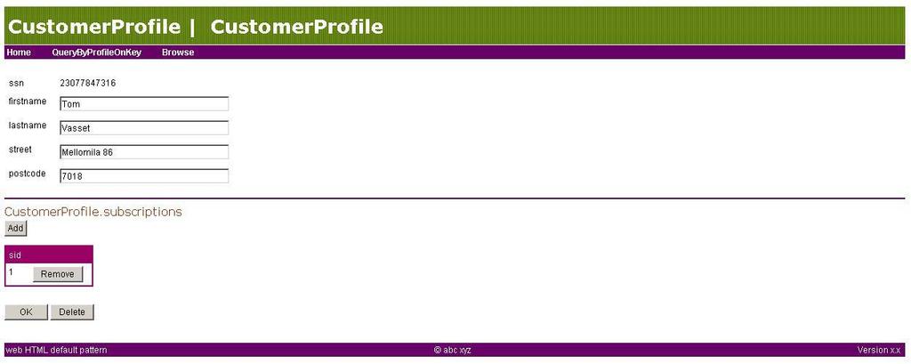
102 6.3.7 Screenshots Figure 6-19: OptimalJ generated web application, main menu Figure 6-20: OptimalJ generated web application, customer profile Figure 6-21: OptimalJ generated web application, update customer profile 102
103 6.3.8 Summary Table 6-2 summarizes our OptimalJ and MDA development investigation. Investigation aspects Investigation attributes OptimalJ Modeling PIM Domain model in a subset of the UML class diagram. PSM UML Profiles Model semantics and/or constraints Application model, divided into DBMS, EJB and Web specific application models. OptimalJ does not seem to use UML Profiles as we know them by stereotypes or tagged values. The reason for this is that OptimalJ only has a small subset of UML in the models the developer works on. Stereotypes and tagged values are not supported at all! OptimalJ might use the UML Profile concept internally, but we did not find any information confirming this. OptimalJ has two different constraints: Unique constraints, which relates to primary keys Attribute constraints, which are divided into: o Ranges o Business expressions o Regular expressions These constraints are automatically added to the model, by model generation. OptimalJ checks the domain model for consistency, when generating the application model. There is no OCL support. Pervasive Services OptimalJ does not support any Pervasive Services (transactions, security etc.) at the PIM (domain model) level. There is support on the PSM (application) level, e.g. for authentication and authorization Domain Facilities There are no domain models (normative PIMs) for any specific domains (e.g. finance, telecom etc.). This is not very surprising, as there is yet much work to be done by the OMG on Domain Facilities. Model transformations PIM PIM There is only one level of PIMs in OptimalJ, thus no PIM-to-PIM transformations. PSM PIM OptimalJ supports model transformation from PSM DBMS application models to PIM domain models. PIM PSM The generation of application models, DBMS, EJB and Web. PSM PSM There are only one level of PSMs in OptimalJ, thus no PSM-to-PSM transformations. Model and artifact/code synchronization OptimalJ synchronize the models and code in Model- Code Repositories (MCRs). The.mrc files provide model-to-code synchronization for updates, deletion and renaming of model elements. Customizing source code is done by editing so called free blocks, which are protected areas that survive repeated code generations from the model. Transferring changes in the artifact/code to the model is not supported. Artifact/Code Extent of the OptimalJ generates 100% of the artifacts/code needed for 103
104 generation artifact/code generation a database, EJB and Web maintenance implementation of the domain model. What artifacts are DBMS implementation generated o SQL scripts EJB implementation o EJB 1.1 or 2.0 implementation and helper classes. o Deployment descriptors. o JAR files. Web o JSPs and servlets based on a maintenance pattern, using an extension of the Apache Struts web application framework. Ease of use for customization and change o The WAR file Working with the customized code in the IDE was relatively simple. Free and protected blocks where intuitively separated. Understanding the generated code was not easy, as OptimalJ generates the application using their own technology framework, it being EJB or Web. There was also little explanatory literature (user guides or tutorials) on what the tool actually generated and how the generated artifacts worked together. Integration with legacy applications Deployment and implementation It was also very difficult to navigate from errors in the generated code to which domain or application model elements that could be erroneous. Integration support Model import from XMI Reverse engineering of Java signature files DBMS import from JDBC CORBA IDL import JCA COBOL Web Service WSDL/XML import Extent of integration We tried XMI import, Java reverse engineering and the JDBC DBMS import. The DBMS import worked best for our application and the domain model (PIM) was (with some modification) made entirely from the imported DBMS model. Deployment support Optimal support several J2EE application servers, including BEA WebLogic, IBM WebSphere, Sun ONE and Compuware OptimalServer, Oracle9iAS. Deployment descriptors and other artifacts specific to the selected application server are automatically generated. Evolution Customization of artifacts/code needed for deployment Portability Management and Evolution Redeployment Our experimentation found that there were issues with the generated descriptors, and deployment on the application servers we tested. None (in theory, though we experienced otherwise in our experimentation, see 6.3.5) OptimalJ advocates MDA development, but is currently a J2EE specific development tool. Porting to other platforms,.net for our experimentation was not supported. This had to be done by exporting the domain model by XMI and using another tool for the.net development. Table 6-2: OptimalJ MDA development investigation, summary 104
105 6.4 Developing with Objecteering/UML The following sections describe our MDA development work with Objecteering/UML (Enterprise Edition for Java version 5.2.2). If the reader is unfamiliar with Objecteering/UML, refer to section 6.3 for a brief introduction Legacy integration As described in section the case study details section (5.2), for our MDA development we had a legacy customer administration application to extend and refine. This included: An existing Oracle database, with SQL scripts and a Rational Rose model of the database schema. Application source code (Java) and Rational Rose UML model of this. Objecteering/UML has the following features for legacy integration: Model import from XMI Reverse engineering of Java class files to UML models. The legacy integration gave the following results: 1. Rational Rose does not support XMI export and we didn t find any software to convert Rational Rose models to XMI. This effectively stopped any reuse of the legacy models. 2. The reverse engineering of the Java class files gave us models of varying quality (in some cases quite wrong!). Consequently we had to remodel the legacy system in Objecteering/UML as a PIM and to further refine this model for our MDA development. 105
106 6.4.2 Platform independent models Figure 6-22 shows the PIM, which as explained in the previous section, was the legacy application remodeled in Objecteering/UML. Methods and attributes are not shown for brevity. The CustomerAccess class is added for authentication of the customers for the Web portal application. Other changes to note from the legacy application that the database connectivity class (DBAccess) and the two GUI classes (MainGUI and MessageDialog) have been removed. The reason for this is that they are specific for the legacy application and not reusable for our web portal implementation. We also include figure 6-23, which is a small subset of the PIM, including the Customer and Subscription part. The reason for this is that the further experimentation will be limited to these classes, mainly for model readability, as the generated models were very large. Figure 6-22: Objecteering/UML PIM Figure 6-23: Objecteering PIM, customer and subscription subset A problem we experienced with our modeling was that Objecteering/UML has (currently) no profile for Web applications. One could say that we should have expected this, as the OMG has as yet not specified such a profile. We could of course have made our own profile, as 106
107 Objecteering/UML has a UML Profile Builder, but the focus of this investigation was not on extending these MDA development tools. Consequently we did not get any tool support for the modeling and generation of the customer Web portal part of our application. We decided to focus for the rest of the Objecteering/UML MDA development on the EJB support and not to develop the Web portal Platform specific models Figure 6-24 shows a subset (the same subset as in figure 6-23) of our PSM for EJB. The model was automatically generated from the PIM. This was done by selecting the EJB (2.0) profile, or module as Objecteering/UML denotes them, and to transform the classes into EJBs. As you can see from the figure, all the needed EJB specific interfaces, methods and attributes are added to the model. Note that the <<EJBPrimaryKey>> and the <<EJBCmpField>> stereotypes had to be set after the generation. The automatic EJB model generation was very convenient, but a closer look at model uncovers a serious problem with this transformation; the association between the customer and the subscription classes in the PIM has not been preserved. Consequently you have to remodel all the association between the classes, by adding these as EJB relationships! This was mildly said very annoying, as you (depending on how many classes you convert to EJBs) practically loose large parts of your PIM modeling work when you do the EJB transformation. We also experienced problems with the attribute types available. As you can see from figure 6-24, the bounduntil and registrationdate attributes in the SubscriptionEJBBean are both undefined as it was not possible to select a Date data type. The consequence of this was that we had to set the type of the attribute ourselves after the code was generated. 107
108 Figure 6-24: Objecteering/UML EJB PSM Artifact/code generation and implementation From the PSM model in figure 6-24, Objecteering/UML generated the EJB classes and interfaces. When we tried to compile the code generated, we encountered a problem regarding the Objecteering/UML makefiles. These makefiles are generated for each of the model classes for compilation, and some of the generated makefiles did not run in the make tool used. We contacted Objecteering about the matter, but we never solved the problem (which was probably ours as they had never encountered problems with this before). Just for the record, we compiled the generated code outside the Objecteering/UML environment and it was fault free. So why did this cause a problem for us? When we generate the EJB JAR files in Objecteering/UML, the EJB source code is compiled first (using the erroneous makefiles). Thus we were not able to generate the EJB files for deployment, effectively stopping us from further experimentation. 108


109 6.4.5 Deployment and testing Objecteering supports the most popular J2EE application Servers, including IBM WebSphere and BEA WebLogic and more. Deployment specific information, in our case different EJB properties, is separated as platform specific and unspecific properties. Figure 6-25 shows the Objecteering/UML WebLogic specific database properties (needed for EJB containermanaged persistence) and Figure 6-26 show a menu over the different WebLogic specific EJB properties that has to be configured. Figure 6-25: WebLogic specific database properties Figure 6-26: WebLogic specific EJB properties We wanted to deploy and test our EJB application on a few of the supported application servers, but this was effectively stopped by the problem described in the previous section. We would in any case have had problems with the deployment, as Objecteering/UML currently only supports old versions of the application servers we checked out, which where WebSphere and WebLogic. The versions supported, which is WebShere 4.0 and WebLogic 6.0 respectively, was at the time of our case study development no longer available for evaluation download (which was the way we could get our hands on the needed software). Consequently (and very unfortunately) there was no deployment done of the Objecteering/UML generated application. 109
110 6.4.6 Evolution Following the work described in the case study details (5.2), the system was to evolve by porting the application to another deployment platform, using another programming language. In our case, this was to port the application from J2EE to Microsoft s.net framework. The Objecteering/UML edition we tested did not have any.net specific support (currently there is no Objecteering support for.net). We could of course have generated a C++ (with the Objecteering C++ module) specific PSM model and thus get C++ class skeletons for our.net application 11. We still decided to not develop the evolution/porting part, as support was limited to C++ code generation only. What is important to note is that there would in any case have been substantial work involved in doing such a porting without support from the tool Summary Table 6-3 summarizes Objecteering/UML and the MDA development investigation. Investigation aspects Investigation attributes Objecteering/UML Modeling PIM There is no clear PIM concept in the tool. You start out working with an analysis UML model. PSM There is no clear PSM concept in the tool. By selecting the various UML profiles, you get context specific menus for these regarding code generation etc. UML Profiles The tool has several UML Profiles, called modules, including Java and EJB (1.1 and 2.0) which we investigated. Model semantics and/or constraints The tool has OCL support, but no code are generated for these constraints. Pervasive Services Domain Facilities Model transformations PIM PIM None. PSM PIM Not supported. PIM PSM PSM PSM Model and artifact/code synchronization There is no PIM support for any Pervasive Services. There is no domain specific (finance, telecom etc.) modeling support. You can transform a PIM into e.g. an EJB specific implementation of this model. Note that the associations in the initial PIM are not preserved in the generated PSM. Java classes to EJBs. The customized artifacts/code is protected from subsequent model-to-artifact/code generation by modifiable zones. Artifact/Code generation Integration with legacy applications Extent of the artifact/code generation What artifacts are generated Ease of use for customization and change Transferring changes in the artifact/code to the model is not supported. The code generated for the EJBs was only class skeletons, with limited implementation (getter and setter methods etc.) For our EJB implementation, the tool generated the EJB interfaces, implementation classes including the EJB. Primary Key class Not investigated. Integration support XMI model import Java class file import 11 Note: C++ is one of the programming languages the.net framework supports. 110
111 Deployment and implementation Extent of integration Deployment support EJB JAR file reverse engineering We had no XMI to import and thus tried the Java class file import. We found this feature to be very limited, as the models generated were not very accurate. The tool provides EJB deployment support for the following application servers: IBM WebSphere, BEA WebLogic, Iona iplanet and Sun J2EE Application Server. The tool creates the EJB JAR file needed for the selected EJBs, and integrates (the user provides the path) with the external packaging tool for the selected application server. Evolution Customization of artifacts/code needed for deployment Portability Management and Evolution Redeployment EJB specific deployment properties were configured in different EJB property editors, and divided in platform specific and unspecific properties. Not investigated. The Objecteering/UML edition we used did not support.net (currently Objecteering has no.net code generation). Table 6-3: Objecteering MDA development investigation, summary 111
112 6.5 Comparing ArcStyler, Objecteering/UML and OptimalJ This section provides a brief comparison of the three MDA development tools we experimented with in our case study. The focus of this comparison will, as before, be on the important MDA concepts stated in table Modeling PIM and PSM OptimalJ has a clear PIM in the domain model concept. From this model you generate PSM for DBMS, web and EJB. PIM and PSM modeling is rather vague in both ArcStyler and Objecteering/UML, as the two tools do not have a clear distinction between PIMs and PSMs. You start out with an analysis model and select modules (Objecteering) or MDA cartridges (ArcStyler) for the technologies you want to generate code for UML Profiles Both ArcStyler and Objecteering/UML operate with UML profiles for specific technologies. These are called modules and MDA cartridges respectively. OptimalJ does not seem to support UML profiles and has instead based their model transformations and artifact/code generation on a fixed support for EJB, a specific maintenance web application pattern and on different DBMS Model semantics and/or constraints Both ArcStyler and Objecteering support OCL for defining constraints, but none of the tools generate code from these constraints. OptimalJ has no support for OCL, but have an alternative constraint mechanism that are divided into unique constraints and attribute constraints. The OptimalJ constraints are reflected in the generated application. None of the tools support any action language or other additional model semantics Pervasive services and domain facilities None of the tools have any pervasive services at the PIM level nor support any normative PIMs for any specific domains. 112
113 6.5.2 Model transformations PIM PIM There are no PIM-to-PIM transformations in any of these tools. As mentioned before, both ArcStyler and Objecteering/UML has no clear PIM or PSM concept, and OptimalJ only has one level of PIM, namely the domain model PSM PIM OptimalJ is the only tool that applies any automatic PSM-to-PIM model transformation. We imported a database specific model through the JDBC DBMS import facility and transformed this model into a domain model (PIM) PIM PSM All three tools support transformation from a PIM to a PSM. This transformation process is more distinct in OptimalJ, as the two other tools does not clearly separate the PIM and the PSM PSM PSM Objecteering/UML supports this by transforming Java classes into EJB implementations. ArcStyler and OptimalJ have no automatic PSM-to-PSM transformation support Model and artifact/code synchronization All three tools use the concept of modifiable and protected areas to protect (from subsequent regeneration) custom insertions in the generated artifacts/code. ArcStyler is the only tool that can reflect changes in the code in the model (by using the tools MDA harvester) Artifact/code generation Extent of the artifact/code generation The extent of the artifact/code generation varies with what part of/type of application the tool is supporting. All three tools can generate 100% of the application for database specific implementations in SQL scripts. They can also generate 100% of an EJB application for a specific application server, but this depends on how much business logic these EJBs contain and if the application is 100% EJB or not. To clarify this: if the EJBs are mainly Entity Beans, which reflects persistent information in the database(s), 100% of the application can be generated. Since none of the tools generate business logic based on the models, any such business logic must be written by the developer. Both OptimalJ and ArcStyler generates web application artifacts/code, but OptimalJ uses a set maintenance pattern giving you a maintenance application for inserting, updating, retrieving and deleting persistent data only. Contrary to ArcStyler, there is no modeling support for (other) web applications. 113
114 What artifacts are generated Which artifacts are generated is very similar for the three tools. It s more the contents of these artifacts that vary, depending on how the tool vendors have decided to implement the specific technology in question. Examples of generated artifacts are: Database implementation in database specific SQL scripts. EJB. o Implementation classes. o Application server specific deployment descriptors and any other deployment server specific artifacts. o JAR and EAR files. Web application (ArcStyler and OptimalJ) o JSPs and Java source code. o XML configuration files Ease of use for customization and change All the three tools had intuitively separated the generated code from the areas that were modifiable and intended for custom code. In this respect it was easy to customize and change the generated artifacts/code. It was not easy to understand and use the generated code 12. All the tools generate artifacts/code based on their own framework or implementation style, meaning how they feel the platform specific models should be implemented for the specific technology. OptimalJ for instance generate code based on its own extension of Suns EJB interfaces. A general trait is that the tools provide very little documentation of what artifacts/code is generated based on the specific models, especially with regards to what is automatically implemented and how this implementation works. For non-expert users this constitutes a major challenge, as potentially large parts of the artifacts/code is written by the tool with no or very little documentation (javadoc, inline comments etc.). Most developers that have worked with code written by others will probably testify that it can be challenging to understand and use this code Integration with legacy applications Integration support Common for all the three tools are that they support XMI model import/export and reverse engineering of legacy applications from varying technologies, typically Java and C++, into PSMs. The quality of these reverse engineered models varied a lot (in some cases quite wrong) and none of the tools supports any model transformation from these PSM reverse 12 Note that these tools were new to us and with no prior experience (though some with ArcStyler), we obviously find it harder to work with the generated artifacts/code than an experienced user will. 114
115 engineered models to PIMs. The exception here is the JDBC database import we used in OptimalJ, where we produced a PIM from the database specific PSM Deployment and testing Deployment support The deployment support we tested was the generation of deployment descriptors for specific application servers produced by the three tools. Examples of supported applications servers are IBM WebSphere and BEA WebLogic. Our experience with these generated deployment descriptors is that you can t always trust that they are 100% correct. If they are not, finding and correcting any errors can be very difficult. Another problem we experienced is that the tool vendors seem to have problems keeping up with the application server releases. The newest releases (and in some cases not the previous release either!) were often not supported, forcing the developer to create the deployment artifacts Customization of artifacts/code needed for deployment In theory, the tool vendors promise that no customization of the deployment specific artifacts is needed for deployment. We experienced otherwise in our development, where none of the tools generated 100% complete deployment descriptors for the selected application servers. The problems we experienced with the EJB deployment relate to issues with these development tools and will probably be corrected in future releases. What we can say for sure is that to support several application servers (not to mention the different releases of these servers) and to generate correct deployment artifacts for these seems to be challenging for the tool vendors Evolution Portability, Management and Evolution and Redeployment The current MDA development tools typically support a set of specific technologies and this applies to the three tools we have experimented as well. For these three tools, the J2EE technology is given the main focus and support. Thus the tools did not support to port the application from our initial J2EE implementation to.net, as we were hoping. We could have generate class skeletons for our application in C++ (Objecteering) and C# (ArcStyler) that would support such an evolution of the application, but the tools had no deployment or web application modeling/generation support for.net. Consequently we did not finish the planned move to the.net framework. 115
116 7 Discussion and result analysis 7.1 Tool survey The first interesting result of our tool survey was the number of tools we found announcing support for the MDA. Finding close to thirty tools were positively surprising, especially since the MDA technology is new and does currently not have a precise specification. Needless to say, one can debate if all of these tools deserve to be labeled MDA development tools, but that is a matter of opinion until a specification is ready. The bases for this tool analysis are the findings from chapter 3. It is important to note that the results described here are derived from all of the tools included in the tool survey, not only ArcStyler, OptimalJ and Objecteering/UML. In section we look at some of the main MDA development tool survey findings, but first off, let s try to classify these tools after some of their typical features MDA development tool classification It was very interesting to see how much these tools varied in their focus and approach to support the MDA. This is also reflected in the Assessment of Model-Driven Technologies Foundations and Key technologies MODA-TEL delivery [8], where they divide the different tools into what MDA focus they have: Focus on action semantics and state machine simulation. Focus on (sophisticated) artifact/code generation. Focus on complete support for specific technologies. Focus on customizable diagrams and views of metadata. Focus on full MDA support (covering all aspects of MDA). We found the typical MDA development tool to belong to one, and more often than not, to more than one of these categories. For our own work, we classified the tools after the following three categories: The Artifact Generator The Metamodeler The MDA Developer These MDA development tool categories are described in the following sections and summarized in table The Artifact Generator The Artifact Generator category contains tools that focus on artifact/code generation with outof-the-box generation support for specific technologies. The tools are in general easy to extend (custom or from the vendor upon customer request) for new technologies, thus often 116
117 featuring an open architecture especially for artifact/code generation, but also for model transformation (PIM to PSM). The most typical characteristics are summarized as follows: No modeling support. Thus the tool either integrates with a 3 rd party UML tool and/or imports UML models in XMI format. Extendible and often based on open architectures. No or very limited legacy integration/reverse engineering support. Typically smaller in size (and in cost) and more specialized than the other tools. A fact that was a bit surprising with the tools we classified as Artifact Generators was that some of them do not support custom UML profiles. In our opinion, this seriously inhibits extendibility, as UML profiles are important to transform between PIMs and PSMs and from PSM to artifacts/code. The reason for this was found to be that some of tools use other concepts than UML profiles to generate the artifacts/code. Tools in this category include SmartGenerator, XCoder, iqgen, JeeWiz and Codagen The Metamodeler The Metamodeler category contains tools that are not constrained to UML profile based models, but can build models based on arbitrary MOF-based metamodels. We only encountered two tools that fit into this category, namely Metabase and Metaedit+. These tools were quite different and we did not find many similar characteristics. Metabase is a metadata management tool, while Metaedit+ is more a development tool supporting other modeling standards than the UML. The characteristics of this category were thus limited to: Supports models built on arbitrary MOF-based metamodels The MDA Developer The MDA developer category tools typically support (or try to support) most aspects of the MDA development process, from UML modeling to artifact generation and deployment. These tools also provide support for specific technologies, but vary in how well they support custom extensions to new technologies. Another aspect that varies significantly is the support these tools have for legacy integration. Most provide some support for code to (platform specific) model reengineering, but very few support transformation from PSM to PIM models. Typical features are summarized as follows: Supports UML modeling (in visual diagram tools). Supports an action language, OCL or another mechanism for semantics/constraints, but few of the tools generate code from them. 117
118 Good artifact generation support for specific technologies, but varied support for custom extension of the code generators. These tools have a lot to learn from the Artifact Generators with regards to extendibility. The model and code is synchronized by dividing the generated artifact into protected and modifiable areas. Supports deployment on specific deployment platforms, typically application servers and/or databases. Tools in this category include ArcStyler, Objecteering, BridgePoint, Tau, iuml, XDE, Delphi 7 Studio, OptimalJ and StP. Table 7-1 summarizes our MDA development tool classification. Tool Category Characteristics Tool Examples The Artifact Generator No business modeling support. Thus the tool either integrates with a 3 rd party UML tool and/or imports UML models in XMI format. Extendible and often based on open architectures. No or very limited legacy integration/reverse engineering support. Typically smaller in size (and in cost) than the other classes. The Metamodeler Supports models built on arbitrary MOF-based metamodels. SmartGenerator, XCoder, iqgen, JeeWiz, Codagen Metabase, Metaedit+ The MDA Developer Supports UML modeling. Supports an action language, OCL or another mechanism for semantics/constraints. Good artifact generation support for specific technologies, but varied support for custom extension of the code generators. Supports deployment on specific deployment platforms, typically application servers and/or databases. Table 7-1: MDA Tool classification ArcStyler, Objecteering, BridgePoint, Tau, iuml, XDE, Delphi 7 Studio, OptimalJ, StP 118
119 7.1.2 Survey tool feature analysis MDA development tool feature analysis The MDA development tool feature data can be found in section 3.2, tables 3-2 through 3-9. Let s take a look at some of our key findings: 1. Modeling and model transformations. a. All the tools (except specialized code generators) support visual modeling and UML. Not exactly a surprising finding, as the UML is the default MDA modeling language. The tools vary much in what diagrams they support (class diagrams being the minimum), but a core set of supported diagrams will probably emerge as the tools start implementing the different OMG UML profiles. b. More than half the tools do not support arbitrary UML profiles (stereotypes, tagged values). We found this to be a bit surprising and a problem especially with regards to extendibility. UML profiles are very important in the MDA, not only because the OMG has and will specify such standards for different domains, but also for companies to be able to create standard inhouse models for their specific business. c. Less than 10% of the tools have an action language editor / simulator and only 30% of the tools support OCL or another constraint mechanism. Only a small minority of the tools generate code based on this added semantics. Artifact/code generation is in our opinion critical for the success of the MDA. Support for action languages and constraints preferably in OCL increase model semantics, but few tools take advantage of this for platform specific model transformation and code generation. We feel such semantics should be transferred to the platform specific models and in the end to the generated code. Hopefully this will improve with the UML 2.0 specification, which promises better support for model semantics. d. Almost none of the survey tools (with one exception) allow customization of the model transformation process, and about 70% of them do not support debugging of this process. There is in other words almost no customization and very little debugging support in these tools for model transformations. One of the reasons for this is that many of the tools simply do not support automated transformations from PIMs to PSMs and even more seldom from PSMs to PIMs. This transformation process is more often than not left to the developer. This is an area that we feel the tools have a large improvement potential. e. 85% of the survey tools support XMI import/export. The majority of the remaining 15% say they plan to support this in future releases. 119
120 XMI model export/import is important for both model interchange between different developing tools and for reuse of existing models. We expect this number to creep up under 100% in the near future. 2. Artifact/Code generation a. Only half the survey tools support model and artifact/code synchronization. We found this to be a very surprising result. Model and artifact/code synchronization is in our opinion essential when you work with MDA development. Changes in the model should be updated in the code and vice versa, as the two should essentially be different views of the same thing. The tools that did not support this synchronization were typically Artifact Generators, either based on XMI input or in integration with UML modeling tools, but there are occurrences of standalone development tools that do not support this synchronization. For many of the Artifact Generator tools, supporting such synchronization may be difficult, because it requires a tighter integration with the modeling tool. This only elevates the importance of an open architecture, as it opens up possibilities of such integration. b. 50% of the survey tools have model-to-artifact/code generation debugging/consistency check support. The model to artifact/code generation should definitely have consistency checks, to guarantee that the model and the generated code are consistent. Most of the tools do at least provide a high-level consistency check of the model before generation. The relatively low percentage is probably because of the debugging part of the question. c. 2/3 of the tools support customization/extension of the artifact/code generators. 13 The generated artifacts/code should conform to best practice for the technology in question, but what constitutes best practice probably varies from domain expert to expert, and between the different tool vendors and their generators. Customization and extension of these artifact/code generators enables the companies with their own domain and technology experts to create/enforce their own coding standards. Our Artifact Generator class of MDA development tools is good at supporting such customization/extension, while many of the standalone development tools have improvement potential here. 3. Integration with legacy applications a. About 50% of the tools support reverse engineering of models from legacy applications and less than 40% support PSM to PIM model transformation. Legacy applications will (unfortunately) have a part in many development projects, and no less in MDA development. The legacy integration that is supported is typically reverse 13 Note that the survey lack data for as many as 40% of the tools for this question. Based on browsing the missing tools product information, we expect the number of tools to be lower than 2/3. 120
121 engineering Java, C and C++ code, but our experience show that the models generated from such reverse engineering vary much in quality, often requiring substantial customization. The fact that less than 40% of the tools support automatic PSM to PIM transformations were a bit disappointing, and as with the code reengineering, our experience show that these models vary much in quality. We feel both these features are important for legacy integration and reuse. The reason for both the low support percentage and the varying model quality might be because these features are difficult to implement. b. Less than 20% of the tools generate legacy wrappers for legacy applications Another way of integrating with legacy applications is by the generation of legacy wrappers. A legacy wrapper for a specific technology wrap around the legacy components to integrate them in the new application. Few tools support such legacy wrappers and we have (unfortunately) no experience with MDA development tools generating such wrappers. 4. Open architecture, standard conformance and extendibility a. 2/3 of the survey tools claim they have an open architecture for artifact/code generation, but only 25% say the same about model transformations. Finding information about open architecture was harder than we expected, consequently we were only able to find information from 60% of the tools about this. Judging by the product information on the missing 40%, we expect the numbers to be even lower (especially on the open architecture for artifact/code generation question). It is especially tools that classify as Artifact Generators that features an open architecture for artifact/code generation. The tools aiming to support most of the MDA development process by themselves tend to provide their own, closed solutions for this generation. As mentioned before, the standalone MDA development tools have a lot to learn from the smaller artifact/code generators with respect to opening up their generation architecture. Model transformations (if supported at all) are as we have seen seldom customizable and few of the tools have any debugging support for them. With our focus here, we can also add that few follow an open architecture. In our opinion this very much limits custom extendibility and control over the model elements that are generated. Model transformations are one of the MDA concepts that we should expect better support for in the next generation of MDA development tools, especially with regards to customization, extendibility and having an open architecture. Table 7-2 summarizes the key findings in our MDA development tool survey. Aspects Modeling and model transformations Key findings a. All the tools (except specialized code generators) support visual modeling and UML. b. More than half the tools do not support arbitrary UML profiles (stereotypes, tagged values). c. Less than 10% off the tools have an action language editor / simulator and only 30% of the tools support OCL or another constraint mechanism. Only a small minority of the tools generate code based on this added 121
122 semantics. d. Almost none of the survey tools (with one exception) allow customization of the model transformation process, and about 70% of them do not support debugging of this process. e. 85% of the survey tools support XMI import/export. The majority of the remaining 15% say they plan to support this in future releases. Artifact/Code generation a. Only half the survey tools support model and artifact/code synchronization. b. 50% of the survey tools have model-to-artifact/code generation debugging/consistency check support. c. 2/3 of the tools support customization/extension of the artifact/code generators. Integration with legacy applications a. About 50% of the tools support reverse engineering of models from legacy applications and less than 40% support PSM to PIM model transformation. b. Less than 20% of the tools generate legacy wrappers for legacy applications. Open Architecture, standard conformance and extendibility a. 2/3 of the survey tools claim they have an open architecture for artifact/code generation, but only 25% say the same about model transformations. Table 7-2: MDA development tool survey, summary of key findings 122
123 Technology features The technology feature data can be found in section 3.3.2, tables 3-8 and 3-9. Most of the information here speaks for itself, but a few comments are in order. Most of tools either provide support for Sun s J2EE, Microsoft s.net framework or both. This is not a surprising observation as these two development frameworks are very popular with the development community at the moment. CORBA is not far behind in popularity, with the relatively new Web Service (SOAP) technology not quite gaining the same level of support. Most of the tools support more than one programming language and the language support typically follows which development community (J2EE or.net) the tool is aiming at. Java is supported by most of the tools and the.net specific tools typically support C++, Visual Basic and/or C#. Application servers and databases capture the main focus of the tools deployment support. The applications servers are typically popular J2EE application servers, e.g. IBM s WebSphere or BEA WebLogic, and the support is typically the generation of the application server specific deployment descriptors. Many of the MDA development tools we investigated integrate with other development tools to provide better functionality for the different steps in the development process. This is something we expect future MDA development tools to do even more, as few of these tools can alone support the entire application lifecycle. As the current MDA development tools focus on modeling and artifact/code generation, they typically integrate with specific IDEs for custom implementation, e.g. Borland s JBuilder and the open source Eclipse IDE. The tools that specialize on code generation integrate with UML modeling tools, e.g. Rational Rose. To summarize the technology feature analysis the MDA development tools we investigated pretty much follow the development community s demands in which technologies they support. J2EE and different J2EE application servers, different database technologies and the.net framework are the technologies the majority of the tools support, typically for artifact/code generation and legacy integration/reengineering. 123
124 7.2 Case study Through the work with our case study we have seen many of the positive and negative consequences of working with the current state-of-the-art MDA development tools. The following two sections discuss and analyze the most important strengths and weaknesses found in our experimentation MDA development supported by current tools, strengths Reduced development time The first and foremost positive effect of MDA development with the current MDA development tools can be reduced development time. We emphasis can here because our experience show that this largely depends on what application you are developing and what support the tool provides for artifact/code generation and deployment. If you are developing a 100% J2EE EJB application from scratch (read: with minimal or no legacy integration), an MDA developing tool like OptimalJ can generate 100% (depending on how much business logic the application contains) of the application from the PIM. This includes SQL scripts for the selected DBMS, EJB source code and deployment descriptors for the selected application server. Some of the current MDA development tools also incorporate internal deployment and testing environment, letting the developers concentrate on testing and verifying application functionality without worrying about deployment details etc. Needless to say, this reduces development time significantly, especially as the application developers can move the focus from deployment and implementation specific details, to designing and capturing the business structure and behavior in the system models Increased degree of correspondence between the design and the implementation An important and challenging aspect of software development is to produce a design and corresponding implementation that fulfills the set of initial system requirements. The software industry has seen several examples of large development projects that fail, many due to the developed system not solving the initial problem adequately. Current tool supported MDA development includes transformations between PIM and PSM (though we feel this is currently not well supported) and artifact/code generation based on this PSM. The PSM and the artifacts/code are synchronized typically by modifiable and protected areas, and some of the tools (e.g. ArcStyler) can update the model based on changes in the artifacts/code. In our opinion, these automatic model transformation and artifact/code generation increase the degree of correspondence between the design and the implementation. The consequence of this increased correspondence, obviously depending on how well the design captures the system requirements, is a better chance of producing the application that fulfills the requirements set initially. 124
125 Increased code quality The MDA development tools have artifact/code generators for several different technologies that both generate different code and generate code differently. The common denominator is that these generators are made by experts on the technology in question, producing bestpractice code. As (preferably) large parts of the application are generated by the development tool, the artifacts/code generated should in general contain fewer errors than if written by the developer. The consequence is increased application quality Application portability The MDA development tools we experimented with leverage application portability. This portability was in our experience restricted to the following: Programming language portability. Code can be generated for several programming languages, typically Java and C++, but the generated code is often limited to class skeletons. Database portability. Current DBMS have small syntactic differences in their SQL, and the current MDA development tools ensure portability by generating specific SQL scripts for the selected DBMS. J2EE Application servers. The tools generate deployment descriptors which vary from application server to application server. Note that we experienced issues with quite a few of these generated descriptors, with regards to their correctness, but the feature is there. This application portability can significantly speed up the process of porting an application to another technology. The consequence is reduced development time MDA development supported by current tools, weaknesses The MDA development tools are complex and can be difficult to use Our general experience with the current MDA development tools are that they can be complex and difficult to use. These tools work with complex technologies, large standards and have to provide many sophisticated features regarding model transformations, legacy integration and artifact/code generation. The developer works with (possibly) several levels of model (PIM, PSM) abstractions, complex generated artifacts/code not only for a specific technology, but following some coding/implementation style decided by the tool generator. 125
126 Bundle this with limited documentation and few comprehensive tutorials and you get a need for substantial user training to master these tools. As for any other sophisticated tool, many of the MDA development tool vendors arrange courses for their customers, and after experimenting with three of these tools ourselves, we clearly understand why The generated artifacts/code can be difficult to work with The generated artifacts/code should follow best practice for the technology in question, but what constitutes best practice seem to vary from domain expert to domain expert. With this in mind, it came as no big surprise that the artifacts/code that was generated differed substantially between the different tools we investigated. All of them turned out to have their own way of generating the artifacts/code for the different technologies, often based on their own framework and coding/implementation style. For a non-expert user, it was difficult not only to know what artifacts were generated from the models, but more importantly how the generated artifacts/code work together. In theory the developer should not need to worry about these issues, as the application implementation is more or less automated, but what do you do when something in the generated artifacts/code is wrong? You obviously have to check the model you generated the artifact from, meaning navigating from errors in the artifact/code to the models Navigating from errors in the generated artifact/code to the erroneous model elements can be difficult Let s say the generated code does not compile. The typical MDA development tool (or any other development tool for that matter) would probably indicate the line in the code that is erroneous. How do you fix the problem? Do you change the artifact/code (which would require knowledge of how the generated code works) or try to navigate to the model element that has generated the error? Changing the artifact/code does not solve the problem if the erroneous code is not custom inserted. If it isn t custom, the code should be protected and in a tool like OptimalJ you wouldn t be able to modify it at all. No, the solution must be to navigate to the model element that is responsible for the error. This was found to be quite a challenge in the tools we investigated, as it required in-depth knowledge of both the implementation technology (e.g. EJB) and the development tool s (e.g. OptimalJ s) mapping from PSM to artifact/code for this technology. None of the tools had a clear connection between the model elements and the artifact/code that it generated Poor PIM modeling and model transformation support Many of the current MDA development tools have poor PIM modeling and model transformation support. 126
127 The PIM and PSM are often not separated and thus no model transformations are supported either. Both ArcStyler and Objecteering/UML fit in our opinion with this description, although the Objecteering/UML tool has a Java class to EJB model transformation feature. A reason for this can be that few of the current MDA development tools have been developed with the MDA in mind from the start. Many of the tools are either UML modeling tools that have been modified or adapted (as best) to fit with the MDA concept, or they are Tools supporting specific technologies and has put UML modeling and the MDA on top of this support. The tools we investigated tend to focus on supporting specific technologies, and have thus not found the need for the extra PIM level of abstraction. You start out directly with a PSM model for the technology largely because the tool does not support other alternatives for that technology! An example here is ArcStyler and OptimalJ s support for J2EE web applications. As the tools do not support artifact/code generation and deployment for any alternative web application framework (e.g. ASP.NET), there is no profiles for PIM web application modeling. In general the PIM concept, e.g. in ArcStyler and Objecteering/UML, is more related to programming language independence. You start out with an analysis UML class model that is programming language independent, and when this model is finished you refine it manually to the (supported) programming language of your choice. The generated code is mostly class skeletons, with little or no generated logic or behavior. OptimalJ is the only tool of the three we experimented that truly has a PIM concept, but the implementation or platform specificity is limited to EJBs, DBMS applications and a predefined maintenance web application. None of the tools from our experimentation has the capability of modeling a complete platform independent distributed enterprise system, where you transform this PIM to a PSM in e.g. J2EE or.net. We believe this will improve as the OMG adopt specifications for PIM modeling, as have been done with the UML profile for Enterprise Distributed Object Computing (EDOC) [21]. None of the tool we have investigated currently supports this UML profile specification Poor business logic modeling and respective artifact/code generation capabilities The current MDA development tools we experimented with are far from the holy grail ; platform independent design and modeling (e.g. of large, enterprise systems) that assisted by MDA development tools gives you 100% artifact/code generation and automatic deployment on the platform(s) of your choice. One of the major sources of improvement to reach such an ultimate goal is in the area of business logic modeling and the respective artifact/code generation capabilities. The models that the current MDA development tools use for artifact/code generation is mainly structural, in the sense that it is largely class diagrams which are the (model) source for the artifact/code generators. Necessary deployment information is gathered through GUI s 127
128 in the tools, which are specific for the technology in question. The class diagrams contain information about how the different application elements relate to one another, how they are associated and structured, but say nothing about how they work by themselves or together, how they make up possibly distributed components etc. The consequence of this structural focus for artifact/code generation is that business logic and behavior is only captured in the models, and not reflected in the generated artifacts/code. Both ArcStyler and Objecteering support behavioral diagrams, e.g. sequence, state chart, activity and collaboration UML diagrams, but these are not used for artifact/code generation. The same is unfortunately true for the implementation/environment diagrams, e.g. component and deployment diagrams. This is in our opinion an area the tools have a large improvement potential and probably several challenging tasks ahead of them: utilizing the UML diagram types that are available both for more sophisticated model transformations and for better artifact/code generation. The UML profiles the OMG has currently specified, e.g. the UML profile for EDOC [21], indicate that the tools need to move the focus to behavioral modeling as well. This specification uses activity and collaboration diagrams extensively for behavioral modeling, in addition to the structural class diagrams The developer is more dependent on the development tool When you develop an application in these MDA development tools, you in many respects expect and depend on the tool to do much of the implementation for you through artifact/code generation. You also expect the development tool to help you with deployment on the specific application server, DBMS etc., but what if the tool does not support the technology you need? We found that many of the strengths with current tool supported MDA development disappeared when the tool does not support the technology needed. You would expect that a solution would be to export the PIM to a tool that supports the technology in question, but as discussed previously, many of these tools do not support PIM modeling very well. We also experienced that the XMI export/import feature not always work when you move models between different development tools. Another example is when the tool does not provide deployment support for the platform you are targeting. The developer must consequently do the deployment specific implementation without any tool support, possibly removing much of the model and artifact/code correspondence (maintained by the tools artifact/code generation). The consequence is that the developer is more dependent on the MDA development tool to reap the benefits the MDA promises. 128
129 7.2.3 Summary Table 7-3 summarizes the strengths and weaknesses discussed in the previous sections. Strengths Reduced development time MDA development tools can reduce development time by providing artifact/code generation, deployment and test support. Increased degree of correspondence between the design and the implementation Weaknesses The MDA development tools are complex and can be difficult to use. The tools are complex and require substantial user training to master. There are few comprehensive tutorials available. The generated artifacts/code can be difficult to work with MDA development ensures a higher degree of correspondence between the design (models) and the implementation (artifacts/code). This increases application quality, as the model and the implementation are different views of the same thing. Increased code quality The artifacts/code generated (should) contain fewer errors than if you would write the artifacts/code yourself. The consequence is increased application quality. Application portability The supported application portability can significantly speed up the process of porting an application to another technology. The consequence is reduced development time. Navigating from errors in the generated artifact/code to the erroneous model elements can be difficult When such errors occur, the developer needs to have in-depth knowledge of both the tools generator (what is generated and how the generated artifacts/code works) and the implementation technology in question (e.g. EJB). Poor PIM modeling and model transformation support The tools are in general not very good at PIM modeling and model transformations to PSMs. PIMs and PSMs are often not separated, thus not having any automated transformation between them. Poor business logic modeling and respective artifact/code generation capabilities. The generated code is mainly based on the structural class diagrams, thus limited to class skeletons, data getter and setter methods and methods that implement persistence (e.g. EJB Entity Bean create methods etc.). The developer is more dependent on the development tool Table 7-3: MDA development supported by current tools, strengths and weaknesses 129
130 7.3 The next generation of MDA development tools Areas of improvement The previous sections discussed and analyzed the current MDA development tools from both our MDA development tool survey and our MDA development case study experimentation. The results show that there are many MDA aspects that need improved tool support before we can reap the benefits the MDA promise. The following sections discuss the areas we investigated and which improvements we expect realized in the next generation of MDA development tools Modeling and model transformations 1. The MDA development tools need better PIM modeling support and an increased focus on automatic model transformations to PSMs. Many of the current MDA development tools do not separate the PIM and the PSM. They basically do not contain different levels of model abstractions at all. You start out with an analysis model that you manually refine to fit the technology you want. From future tools, we hope there is a better focus on PIM modeling and better automated support for model transformations to PSMs. These modeling transformations shouldn t be limited to class diagrams and attribute data types, but should include diagrams modeling behavior as well. 2. The OMG has UML profiles for PIM modeling, e.g. the EDOC profile, and the next generation of MDA development tools should implement these specifications. None of the tool we investigated implements the OMG PIM UML profiles. When these profiles are implemented, moving models between MDA development tools will finally have a meaning. If the MDA development tool you are using do not support the technology you want to employ, you can export the PIM model and import it in another tool that supports the technology. It will also make companies able to change MDA development tool vendor and still be able to keep any PIM model base conforming to the standards Artifact/code generation 3. Future tools should improve the generation of artifact/code by utilizing the behavioral UML diagrams, e.g. sequence, state chart, activity and collaboration UML diagrams. The Artifact/code generation today is as previously based primarily on structural models, e.g. class diagrams. This limits the code generation to be primarily structural as well, with little or no generated behavioral logic. The current MDA development tools generate the structure of the modeled application, but very little of how the structural elements work both by themselves and together as application components. 130
131 Legacy integration 4. The next generation of MDA development tools should facilitate better legacy integration by: i. Improved reverse engineering of legacy artifacts/code to a PSM with possible transformations to a PIM for the same legacy application. ii. Providing support for the generation of legacy wrappers around a legacy application, to enable new applications to interact/use this application. Many development projects need to integrate with or build on legacy applications, and this will (unfortunately) be no less true for MDA development. For the developers to be able to integrate with, use or extend existing legacy applications, we feel the MDA development tools needs to integrate with these applications on the model level, e.g. as stated in i) or ii) above. Our work shows that the current tools have very limited legacy integration capabilities. The quality of the current tools reverse engineering varies a lot and in some cases the PSMs generated from the reverse engineering needs a lot of customization to be of any use. Many of the tools do not connect the imported PSM with the legacy source artifacts/code, which in effect do not enable the developer to integrate the application. Another thing we found was that few tools are able to generate a PIM based on the imported PSM, thus removing the possibility of capturing existing applications in a platform independent way, e.g. for porting the legacy application to a new platform/technology Open Architecture, standard conformance and extendibility 5. Future MDA development should provide a larger degree of extendibility and customizability with regards to modeling and artifact/code generation. This does in our opinion leverage the need for open architectures and standard conformance. Many of the current MDA development tools do not provide support for extendibility and customization, most importantly for UML profiles. These MDA development tools are large and complex and cannot support the entire development process and every technology imaginable out of the box. With this in mind, the tools need to make the customers or 3 rd party vendors able to extend or customize these tools to suit their own needs. This can only be done effectively by leveraging an open architecture e.g. for model transformations and artifact/code generation, and to conform to standards, most importantly the OMG standards and UML profile specifications. Hopefully this will make the next generation of MDA development tools able to avoid the fate of the CASE tools from the 80 s; development tools built on a great idea, that grow large and complex, difficult to use, have little in common and that in the end no one wants. 131
132 Table 7-4 summarizes the areas of improvement discussed in the previous sections. MDA aspect Modeling and model transformations Areas of improvement The MDA development tools need better PIM modeling support and an increased focus on automatic model transformations to PSMs. The OMG has UML profiles for PIM modeling, e.g. the EDOC profile, and the next generation of MDA development tools should implement these specifications. Artifact/Code generation Legacy integration Future tools should improve the generation of artifact/code by utilizing the behavioral UML diagrams, e.g. sequence, state chart, activity and collaboration UML diagrams. The next generation of MDA development tools should facilitate better legacy integration by: Improved reverse engineering of legacy artifacts/code to a PSM with possible transformations to a PIM for the same legacy application. Providing support for the generation of legacy wrappers around a legacy application, to enable new applications to interact/use this application. Open architecture, standard conformance and extendibility Future MDA development should provide a larger degree of extendibility and customizability with regards to modeling and artifact/code generation. This does in our opinion leverage the need for open architectures and standard conformance. Table 7-4: Areas of improvement for the future MDA development tools 132
133 7.3.2 A look into the future: What can we expect? First off, we do not expect the next generation of MDA development tools to implement all the improvement suggestions from the previous section. Implementing sophisticated model transformers, artifact/code generators and legacy integrators that push us closer to the holy grail mentioned earlier is a major challenge and will take time. What we do expect and hope is that as the OMG finish the UML 2.0 specification and specify more UML profiles (with PIMs and PSMs for different domains), we will se more sophisticated MDA development tools out there. As these specifications are implemented, we also expect them to add behavioral models to the current primarily structural source of artifact/code generation, thus generate larger parts of the modeled application automatically. We also expect these MDA development tools in a larger degree to use an open architecture and facilitate extendibility for many of their components, especially those regarding model transformations and artifact/code generation. As the developer gets more dependent on the development tool, (s)he needs to be able to extend and customize the tool to suit the developers need. 133
134 8 Conclusion and further work 8.1 Conclusion and summary Our work on MDA has been twofold, divided into: 1. MDA development tool survey, investigating the current state-of-the-art MDA development tools and their features. 2. MDA development case study experimentation with three of the tools from the previous tool survey: ArcStyler, OptimalJ and Objecteering/UML. From this tool survey and case study experimentation, we found that there are currently many tool vendors that support (or claim support for) the MDA, but that their MDA development tools have far from reached their potential in supporting and benefiting from the MDA. In our opinion they need to improve in the following areas: Modeling and model transformations Especially PIM modeling and PIM-to-PSM and PSM-to-PIM transformation support needs to be improved. The PIM concept is weak and almost none-existent in many of the current MDA development tools, but very important in the MDA. The same can be said of model transformations. Artifact/code generation The tools need to include behavioral diagrams, e.g. the sequence, activity and collaboration UML diagrams, as sources for the generation process. This will facilitate better artifact/code generation, as the present tools generation source is primarily the structural class diagrams. Legacy integration As the MDA move much of the focus away from the code and implementation level and up to the models, integration with legacy applications needs to reflect this. Integration tool support such as reverse engineering of legacy code to PSMs or the generation of legacy wrappers are necessary for developers to be able to integrate with, use or extend legacy applications. Increased focus on open architectures and standard conformance The MDA envelops the entire application lifecycle, from requirements to design, implementation, deployment and evolution. No one tool is able to support all these aspects by itself, leveraging the importance of open architectures and standard conformance. The tool vendors would in our opinion benefit from advocating open architectures for concepts such as model transformations and artifact/code generation, enabling users and/or 3 rd party vendor to extend and refine the tools much further than the vendor is able to alone. Conforming to the OMG standards and the UML profile specification will definitely be important, as these emerge for different domains. 134
135 Better support for extendibility and customization We found that the developer were more dependent on the tool, when using an MDA development tool. With this in mind and the fact that these tools in theory have to support every imaginable technology for platform specific model transformations and artifact/code generation, facilitating extendibility and customization will be important. These tools still have far to go, but as the OMG specifies the MDA properly, finish the UML 2.0 specification and their UML profile specification work proceeds, we expect these tools to improve in most of the areas mentioned above. We conclude that the MDA and tool supported MDA development has a lot to offer the software development community, but we need a new generation of MDA development tools, designed with the MDA in mind, to reap the promised benefits of the MDA: interoperability, portability, reduced development time and increased application quality. 8.2 Evaluation of contribution We feel that our work on MDA development and MDA development tool support is a significant contribution to the subject. We would have liked to experiment with more of the MDA development tools found in the initial tool survey, especially those focusing on executable UML, but the time limits of this thesis set a stopper for more such experimentation. When we look back at our tool survey, after doing the case study, we see that there are more features we would have liked to investigate. As the case study revealed that the tools seem to generate code mainly from the structural class diagram, we should have investigated in detail how the tools do their artifact/code generation, e.g. which diagrams are used. Unfortunately, collecting the survey data was too time-consuming to repeat for these added features. Though more case study experimentation and a more extensive tool survey would have been rewarding, we do not think it limits the results from our work as it is presented here. 8.3 Further work There are several possibilities for further work on MDA and MDA development tool support. For the interested reader, we propose a couple of directions for following up our work: 1. Do a trade-off study of development tool supported MDA development vs. traditional object-oriented development. It would have been interesting to see a development comparison between MDA development, supported by the current MDA development tools, and traditional object-oriented development supported by traditional development tools. One can probably argue that the current MDA development tools are generations behind the state-of-the-art traditional development tools, and thus a comparison will currently be unfair, but in our opinion interesting nonetheless. 2. Look closer at the current OMG UML profiles with regards to model transformations and artifact/code generation. 135
136 A closer look at the OMG UML profiles with regards to model transformations and artifact/code generation would have been very interesting. How sophisticated applications can you actually generate from these UML profiles and is there a limit to how much of the application MDA development tools can generate for you? In our opinion the focus here should especially be on behavior/business logic modeling and respective artifact/code generation, as the current MDA development tools have a large improvement potential here. 3. Investigate MDA development coupled with development process models For our development work we used a simple waterfall software process model. This worked well with the MDA development tools we investigated, but does MDA development and MDA development tools in any way limit the choice of software process model? What if we would have used the RUP or XP? Would these process models fit as well with MDA development? An investigation of these issues would have been interesting. 136
137 9 References [1] Farshchian B. A., Jakobsson, S., Berg, E., Coupling MDA and Parlay to increase reuse in telecommunication application development, Workshop in Software Model Engineering, 2002, [2] Architecture Board ORMSC, Model Driven Architecture (MDA), OMG document number ormsc/ , July [3] Kent, S., Model Driven Engineering, In Proceedings of IFM 2002, LNCS 2335, Springer Verlag, 2002, pp [4] Model Driven Architectures for Telecommunications System Development and Operation (MODA-TEL) home page, [5] Object Management Group, Inc., MDA Presentations and Papers web page, [6] Interactive Objects Software, Model Driven Architecture at Work, OMG Newsletter, March [7] Siegel, S. and the OMG Staff Strategy Group, Developing in OMG s Model Driven Architecture, OMG White Paper, November 2001 ftp://ftp.omg.org/pub/docs/omg/ pdf [8] Belaunde, E., Assessment of Model-Driven Technologies Foundations and Key technologies, MODA-TEL deliverable 2.1., December [9] Object Management Group, Inc., Committed Products List, [10] Interactive Objects Software, The Architectural IDE for MDA, Hubert, R. (ed), [11] Interactive Objects Software, ArcStyler Tools Guide, Reference manual for ArcStyler Version [12] OptimalJ product description web site, [13] OptimalJ product preview, 137
138 [14] Apache Struts web application framework web page [15] Objecteering/UML product web site, [16] The JUnit test framework web page, [17] Interactive Objects Software, ArcStyler EJB Tutorial, Reference manual for ArcStyler Version [18] Interactive Objects Software, ArcStyler Accessor Guide, Reference manual for ArcStyler Version [19] Interactive Objects Software, MDA-Security Guide, Reference manual for ArcStyler Version [20] Using OptimalJ OptimalJ 2.2, User documentation shipped with the OptimalJ Architecture Edition 2.2 [21] Object Management Group, Inc., UML profile for Enterprise Distributed Object Computing Specification, OMG specification, February [22] Object Management Group, Inc., Common Warehouse Metamodel (CWM) Specification, OMG specification, October [23] Object Management Group, Inc., OMG Unified Modeling Language Specification, OMG specification, September [24] Object Management Group, Inc., OMG XML Metadata Interchange (XMI) Specification, OMG specification, January [25] Object Management Group, Inc., Meta Object Facility (MOF) Specification, OMG specification, April [26] Interactive Objects Software, ArcStyler User s Guide, Reference manual for ArcStyler Version
139 [27] Lyngset, T. E., Vasset T., MDA (Model Driven Architecture), NTNU, Norway, November [28] IEEE Computer Society web page, Call for Papers: Model-Driven Development, [29] EURESCOM P1149 project web page, Impacts of changes in enterprise software construction for telecommunications [30] Miguel, M., Jourdan, J., Salicki, S., Practical Experiences in the Application of MDA, UML 2002, LNCS 2460, Springer Verlag, pp , [31] Bézivin, J., From Object Composition to Model Transformation with the MDA, TOOLS'USA, Volume IEEE TOOLS-39, Santa Barbara, August [32] DSouza, D., Model-Driven Architecture and Integration: Opportunities and Challenges, Version 1.1. February 2001, available at
, concepts and technologies Model Driven Architecture as standardized by the Object Management Group (OMG) is a new strategy for designing software")
140 10 Appendix 10.1 Appendix A: Model Driven Architecture (MDA), concepts and technologies Model Driven Architecture as standardized by the Object Management Group (OMG) is a new strategy for designing software systems. MDA is not a completely new architecture, but is built on well known standards like Meta-Object Facility (MOF), Unified Modeling Language (UML) and Common Warehouse Metamodel (CWM). One of the main goals for the MDA is to continue to allow the coexistence of different types of implementation technologies and standards, while simultaneously provide a clean separation of the different layers of abstraction. The vision behind MDA, and subsequently MDA itself, addresses the whole lifecycle of a program: From business modeling to system design, to component construction, to assembly, integration, deployment, management and evolution. Figure 10-1: Model Driven Architecture To better integrate both new and old standards, MDA 4. embraces technologies like JAVA, CORBA, XMI/XML,.NET. 5. offers improved portability by making the first part of the design process platform independent. The design is later realized on multiple platforms by auxiliary mapping, or mapped to a specific platform by point mapping. This can either be done automatically by a mapping tool, or manually by a given mapping standard. 6. broadens the usability of standards by improving the integration based on models of relationships across different domain applications. 140
141 The next three chapters are concerned about the concepts, models and OMG standards concerning MDA. The literature study presented here summarize and elaborates on the key points in OMG own article about the technical details of MDA [2] Why the MDA One of the underlying motivations for the MDA concept is to improve the productivity of the software development process. This is meant both as a goal to improve the short-term productivity of developers, and to improve long-term productivity by minimizing software artifacts sensitivity to change. In the early days of IT the introduction of high level languages to some extent abolished the need for programmers that wrote assembly or binary directly. The most effective software development concept in most areas today, is undoubtedly the principle of object-orientation. Encapsulation, inheritance and polymorphism allow applications to be extended without affecting other parts of the system. But new kinds of IT requirements, including dynamic addition to applications at run-time, need new kinds of solutions. A technology that aims to meet these requirements is the MDA. The modeling part of software development will play an extended role compared to earlier. Models will become the primary artifacts developed by humans, and code - at the level defined by today s programming languages will be a derived artifact, generated by tools. This will allow developers to focus on describing business logic and problem concepts in a concise and abstract manner as possible, leaving tools to handle the routine implementation issues [2] Concepts This chapter aims to give a brief summary of the main concepts used in the MDA. A model in the MDA is a representation of a part of the function, structure and / or behavior of the system. A formal specification is one that is based on a language that has well-defined syntax and semantics, and possibly rules of analysis, inference or proof of its constructs. The syntax of a formal specification can be represented both textual and graphical; the semantics should be defined more or less formally. In the context of MDA, a non-formal specification is not a model, but merely an informal diagram or text. Abstraction is defined as a suppression of irrelevant details. Abstraction criteria are useful to determine what level of detail should be included where in a model. The viewpoint, or simply view, of a model is defined by the abstraction criteria of the system. MDA provides guidelines on the architectures of models, where as the abstraction criteria of the viewpoint are a modeling choice. 141
142 A model is refined by making it less abstract. This is a realization of a model. An example of a refinement of a model is the stage where it s transformed from a platform independent model to a platform specific model. MDA also allows zooming on models. Figure 11-2 shows how objects are zoomed on to show different levels of detail. Zooming in shows more details, while zooming out hides details of an object. Figure 10-2: Zooming on objects [2] Figure 11-3 shows how MDA enables zooming on interactions in models. As for objectzooming, zooming in shows more details (if any) of an interaction while zooming out hides these details. Figure 10-3: Zooming on interactions [2] MDA allows the zooming in operation to result in multiple alternative models depending on the refinements. This flexibility is needed to support the ability to model multiple platform specific systems. A Platform Independent Model (PIM) is a formal model where technical details about programming languages and operating systems etc. are excluded. A Platform Specific Model (PSM) is a model where these details are included. 142
143 Models The MDA design strategy is mainly divided into tree key levels of abstraction, namely the Business Model, the Platform Independent Model and the Platform Specific Model. The Business Model is a computation independent model in which computational details are hidden or as yet undetermined. This model can for example be realized by CRC-cards. The PIMs provide formal specification of the structure and function of the system and abstracts away technical details. A Platform Independent Component View is derived by refinement from the Business Model and shows the Computational details of a system without displaying platform specific details. In the refinement to one or more PSMs all technical details are added. Both the PIM and PSM are realized by UML. Figure 11-4 states the relationship between the business model, the PIM and the PSM. As seen from the figure the Business Model is within the scope of the PIM. Figure 10-4: Three different levels of abstraction [2] The idea of abstracting out the precise structure and behavior of a system in the PIM to separate it clearly from the PSM has three main advantages: 1. It s easier to verify the completeness and correctness of a model without platform specific semantics. 2. It s easier to construct a model which can be refined into implementations of several different platforms. The Business Model is also an excellent tool to catch business goals and policies in a computational independent manner. 3. Integration and interoperability across systems can be defined more clearly in platform-independent terms. If there exist generic mapping methods that are shared across multiple applications, it may be possible to automatically transform a PIM to different target PSMs, either fully or partially via some mapping tool. Figure 11-5 shows an example of a shared mapping from a PIM to a CORBA application. 143
144 Figure 10-5: Mapping from PIM to PSM [2] Platform Independent Models in UML As earlier stated, both PIMs and PSMs make use of the UML for modeling. [2] gives the following reasons why UML is preferred over IDL based object models, Java interfaces and Microsoft IDL interfaces: 1. UML is defined using core UML modeling concepts and this enhances the power of MDA. 2. UML can be expressed both textually and graphically. 3. UML models can be semantically much richer than models in other declarative model languages mentioned above, which can express syntax but very little about constraints on usage and behavior such as: Static invariants constraints on combinations of attributes. Pairs of pre- and post-conditions for specifying operations. Whether a single value parameter is allowed to be null. Whether an operation has side effects. Whether subtypes of a super type are disjoint or form a partition. Patterns of specifications, designs and refinements Platform Specific Models in UML Because UML is independent of middleware it is not obvious how a model is specified in a platform specific manner. Decisions on what an UML class actually represent in a PSM context can be defined by using an UML profile. Profiles are a set of extensions to UML which uses the built-in extension facilities of UML, stereotypes and tagged values. Stereotypes label a model element to denote that is has some particular semantics. In the graphical UML notation stereotypes are denoted by angle brackets as shown in figure
145 Figure 10-6: A CORBA stereotype [2] OMG made a complete profile for CORBA, adopted in UML profiles for other platforms can be defined in a similar way to provide the necessary tool for constructing PSMs. To further enhance the semantics of a UML model, notes containing comments and OCLcode can be attached to classes. This is shown in figure 11-7 where a note is attached to the AccountManager class from figure 11-6 to specify that a number must be between 1000 and Figure 10-7: Notes in UML [2] Both stereotypes and notes can be used to enhance the semantics of PIMs as well, but has to be applied in a platform-unspecific manner Mapping One of the key features of MDA is the notion of mapping. Mapping is a set of rules and techniques used to modify one model in order to get another model. Mappings are used for transforming: 1. PIM to PIM. This transformation is used for refining a PIM. Here models are enhanced filtered or specialized in a platform independent manner. The most obvious transformation is the analysis to design model mapping. 145
146 2. PIM to PSM. This transformation is used when a PIM is sufficiently refined to take the step into becoming platform specific. The mapping is based on the platform characteristics. These characteristics should be described using UML. An example of such a mapping is going from a local component model to a commercial existing component model like EJB for J2EE. 3. PSM to PSM. This transformation is needed for component realization and deployment. PSM to PSM is generally related to platform dependent model refinement. 4. PSM to PIM. This transformation is needed for transforming an existing implementation in a particular technology into a platform-independent model. To implement mapping, one needs to know the metamodel of the input and output models and their mapping rules. The execution of transformation rules can be done inside UML via scripting or by using external tools like for example XMI. There are multiple ways to transform a UML PIM to one or several UML PSMs: The first approach is that a human could study the PIM, and manually constructing the refinement between the PIM and the PSM. In the second approach a human takes advantage of known refinement patterns to simplify the construction of a PSM from the PIM. In the third approach an algorithm is applied to construct a PSM skeleton using the refinement patterns in the second approach. These skeletons are manually enhanced. The fourth approach is fully automated using an algorithm that constructs a complete PSM from a complete PIM. This approach would need an advanced refinement tool. Note that the four approaches above do not address the production of executable code from a PSM, only refinement between PIM and PSM. Fully automated transformations are feasible in certain constrained environments. The degree of transformation can be enhanced considerably if: There are no legacy to take into account The model taken into account is semantically rich The transformation algorithms used are of high quality Packages and viewpoints The UML package, a construct for grouping model elements, provides an important modeling element for separating viewpoints and refinements in the context of MDA. A package can import other packages, making them available for its use. Packages help understand MDA since the models being interrelated for integration are typically in different packages. Models of a system from two different viewpoints, unrelated by refinement (or models of two distinct interfaces of a component, or models of two different systems to be integrated) would 146
147 be defined by two different packages like in figure The relationship between the two is defined by a model correspondence (large arrow.) Figure 10-8: Viewpoint correspondence [2] A refinement in the same system can be defined by another correspondence. Refinement is a relation between model elements that can be in different packages, not between the packages themselves. See figure Figure 10-9: Refinement relation [2] OMG standards in MDA MDA is built on several other OMG standards, some of which are illustrated in figure This chapter will attempt to explain how MDA integrates these standards, and to look at the overall picture of MDA The Core The core of the MDA is built upon the MOF, UML and CWM standards. In addition to these standards the core also holds a number of UML profiles. Each profile will contain specialized environments like Enterprise Computing with its component structure and transactional interaction, and Real-Time computing with its special needs for resource control. The idea is that the number of profiles at all times is kept low. Each profile represents the common features of the middleware platforms appropriate for its category of computing, but is independent of any specific platform. 147
148 The first step when constructing an MDA-based application will be to create a PIM of the application expressed in UML using the appropriate UML profile. Platform specialists will transform this application model into one targeted to a specific platform such as EJB,.NET, etc. Standard mappings allow this transformation to be automated. The PSM represent both the business and technical run-time semantics of the application. A PSM is still in UML, but is expressed in a dialect (i.e. a profile) of UML that precisely mirrors technical run-time elements of the target platform Pervasive Services All applications, independent of their context rely on a set of essential services. The list varies somewhat depending on the source but typically includes Directory services, Event handling, Persistence, Transactions, and Security. See outer ring of figure When these services are defined and built on a particular platform, they necessarily take on characteristics that restrict them to a platform. To avoid this, MDA defines such services as pervasive services at the PIM level in the UML. Only after the features and architecture of a pervasive service are fixed, will platform-specific definitions be generated for all of the middleware platforms supported by the MDA Domain Specifications As seen in figure 2-10, outside the outer ring, OMG also tries to integrate domain facility specifications into their MDA concept. Traditionally this has not been an area of modeling with too much focus, but this is to change with the MDA. OMG tries with MDA to standardize the frameworks for standard functions in their application space. The domain facility specifications will be in the form of normative PIMs expressed using UML, augmented by normative PSMs expressed using UML and interface definitions for at least one target platform. An example of this, taken from [2], is a Finance standard for accounts receivable facility that includes a PIM expressed in UML, a CORBA-specific UML model and IDL interfaces and a Java-specific UML model and Java interfaces. XML DTDs or schema generated via XMIbased mapping rules could be included as well. All of which would be normative. Since accounts receivable is an Enterprise Computing application, the normative, platform-specific artifacts would be derived at least partially through standard mappings of the Enterprise Computing profile to the platforms. Today OMG has ten such Domain Task Forces (DTF) and several others are coming soon. These DTFs are shown as rays from the MDA circle in figure Lifecycle IT systems have historically been developed, managed and integrated using a range of methodologies, tools and middleware. The last few years this has to some extent changed to more complete semantic models as well as data representation interchange standards. This 148

149 change is mainly due to OMG- and W3C s work on the area. OMG contributions include CORBA, UML, XMI, MOF and CWM. W3C contributions include XML, XML Schema and the ongoing work of the XML-P working group. The life cycle of an application can vary dramatically depending on whether a new application is built from scratch or if a wrapper is added to an existing application. The cost of enhancement and maintenance of an application far exceeds the cost of initial development. In addition the application lifecycle itself can be quite complex, involving several vendors in each of the lifecycle phases. Hence the need for information interchange and interoperability between tools and middleware provided by different vendors is very important. The MDA supports many of the commonly used steps in model driven component based development and deployment. A key aspect of MDA is that it addresses the complete lifecycle covering analysis and design, programming which includes testing component build or component assembly, and deployment and management. As mentioned earlier the core is based on MOF, UML and CWM. These technologies are used to describe PIMs. A PIM can be refined n-times until the desired system description level is obtained. The model is then transformed to one or several PSMs. The PSM can again be refined as many times as needed. Figure shows a software development lifecycle and the different transformations involved. Figure 10-10: Software Development Lifecycle 149
Computation Independent Model (CIM): Platform Independent Model (PIM): Platform Specific Model (PSM): Implementation Specific Model (ISM):
: Platform Independent Model (PIM): Platform Specific Model (PSM): Implementation Specific Model (ISM):") viii Preface The software industry has evolved to tackle new approaches aligned with the Internet, object-orientation, distributed components and new platforms. However, the majority of the large information
viii Preface The software industry has evolved to tackle new approaches aligned with the Internet, object-orientation, distributed components and new platforms. However, the majority of the large information
All you need are models Anneke Kleppe, Klasse Objecten
 Model Driven Architecture All you need are models Anneke Kleppe, Klasse Objecten Contents Limited Vision on MDA Modeling Maturity Levels Models Model Driven Development Model Driven Architecture MDA in
Developing in OMG s Model-Driven Architecture
 Developing in OMG s Model-Driven Architecture Jon Siegel and the OMG Staff Strategy Group Object Management Group White Paper November, 2001 Revision 2.6 In an accompanying white paper 1, the Object Management
METADATA INTERCHANGE IN SERVICE BASED ARCHITECTURE
 UDC:681.324 Review paper METADATA INTERCHANGE IN SERVICE BASED ARCHITECTURE Alma Butkovi Tomac Nagravision Kudelski group, Cheseaux / Lausanne alma.butkovictomac@nagra.com Dražen Tomac Cambridge Technology
Model Driven Architecture - The Vision
 Model Driven Architecture - The Vision Marko Fabiunke Fraunhofer Institut für Rechnerarchitektur und Softwaretechnik marko.fabiunke@first.fraunhofer.de The Fraunhofer FIRST Institut Your partner We support
The Unified Modelling Language. Example Diagrams. Notation vs. Methodology. UML and Meta Modelling
 UML and Meta ling Topics: UML as an example visual notation The UML meta model and the concept of meta modelling Driven Architecture and model engineering The AndroMDA open source project Applying cognitive
Executive Summary. Round Trip Engineering of Space Systems. Change Log. Executive Summary. Visas
 Reference: egos-stu-rts-rp-1002 Page 1/7 Authors: Andrey Sadovykh (SOFTEAM) Contributors: Tom Ritter, Andreas Hoffmann, Jürgen Großmann (FHG), Alexander Vankov, Oleg Estekhin (GTI6) Visas Surname - Name
QoS-aware model-driven SOA using SoaML
 QoS-aware model-driven SOA using SoaML Niels Schot A thesis submitted for the degree of MSc Computer Science University of Twente EEMCS - TRESE: Software Engineering Group Examination committee: Luís Ferreira
Second OMG Workshop on Web Services Modeling. Easy Development of Scalable Web Services Based on Model-Driven Process Management
 Second OMG Workshop on Web Services Modeling Easy Development of Scalable Web Services Based on Model-Driven Process Management 88 solutions Chief Technology Officer 2003 Outline! Introduction to Web Services!
MDA and Integration of Legacy Systems: An Industrial Case Study
 MDA and Integration of Legacy Systems: An Industrial Case Study Parastoo Mohagheghi 1, Jan Pettersen Nytun 2, Selo 2, Warsun Najib 2 1 Ericson Norway-Grimstad, Postuttak, N-4898, Grimstad, Norway 1 Department
Modelling in Enterprise Architecture. MSc Business Information Systems
 Modelling in Enterprise Architecture MSc Business Information Systems Models and Modelling Modelling Describing and Representing all relevant aspects of a domain in a defined language. Result of modelling
IBM Rational Application Developer for WebSphere Software, Version 7.0
 Visual application development for J2EE, Web, Web services and portal applications IBM Rational Application Developer for WebSphere Software, Version 7.0 Enables installation of only the features you need
developer.* The Independent Magazine for Software Professionals
 developer.* The Independent Magazine for Software Professionals Improving Developer Productivity With Domain-Specific Modeling Languages by Steven Kelly, PhD According to Software Productivity Research,
Model Driven Architecture and Rhapsody
 Model Driven Architecture and Rhapsody Dr. Bruce Powel Douglass Chief Evangelist Telelogic Model Driven Architecture and Rhapsody Abstract MDA, short for Model Driven Architecture, is a unification by
Model Driven Architecture
 Name: Anish Mehta Year: 3 Lecturer: Dr. Wolfgang Emmerich Supervisor: Dr. Graham Roberts Model Driven Architecture For many years architects have been designing buildings by looking at other architects
Practical Model-Driven Development with the IBM Software Development Platform
 IBM Software Group Practical Model-Driven Development with the IBM Software Development Platform Osmond Ng (ong@hk1.ibm.com) Technical Consultant, IBM HK SWG 2005 IBM Corporation Overview The Challenges
Object Security. Model Driven Security. Ulrich Lang, Rudolf Schreiner. Protection of Resources in Complex Distributed Systems
 Object Security TM The Security Policy Company Protection of Resources in Complex Distributed Systems Ulrich Lang, Rudolf Schreiner ObjectSecurity Ltd. University of Cambridge Agenda COACH Project Model
Improving Military Information Technology Through Common Conceptual Models
 Improving Military Information Technology Through Common Conceptual Models Andreas Tolk, Ph.D. Virginia Modeling Analysis and Simulation Center Old Dominion University Presentation Outline Common Conceptual
Model Driven Architecture Targets Middleware Interoperability Challenges
 Model Driven Architecture Targets Middleware Interoperability Challenges by Richard Soley Chairman and Chief Executive Officer Object Management Group and the OMG Staff Strategy Group "CORBA was a powerful
From Models to Components. Rapid Service Creation with
 From Models to Components Rapid Service Creation with Marc Born, Olaf Kath {born kath}@ikv.de Evolutions in Software Construction C O M P L E X I T Y Model Driven Architectures Meta Object Facility and
Reengineering of Distributed Middleware Systems To a Model Driven Architecture (MDA)
") Reengineering of Distributed Middleware Systems To a Model Driven Architecture (MDA) LeeRoy Bronner, Ph.D., P.E., Amen Ra Mashariki Morgan State University Introduction This paper describes the processes,
Reengineering of Distributed Middleware Systems To a Model Driven Architecture (MDA) LeeRoy Bronner, Ph.D., P.E., Amen Ra Mashariki Morgan State University Introduction This paper describes the processes,
OMG Specifications for Enterprise Interoperability
 OMG Specifications for Enterprise Interoperability Brian Elvesæter* Arne-Jørgen Berre* *SINTEF ICT, P. O. Box 124 Blindern, N-0314 Oslo, Norway brian.elvesater@sintef.no arne.j.berre@sintef.no ABSTRACT:
Integration With the Business Modeler
 Decision Framework, J. Duggan Research Note 11 September 2003 Evaluating OOA&D Functionality Criteria Looking at nine criteria will help you evaluate the functionality of object-oriented analysis and design
Appendix A - Glossary(of OO software term s)
") Appendix A - Glossary(of OO software term s) Abstract Class A class that does not supply an implementation for its entire interface, and so consequently, cannot be instantiated. ActiveX Microsoft s component
Appendix A - Glossary(of OO software term s) Abstract Class A class that does not supply an implementation for its entire interface, and so consequently, cannot be instantiated. ActiveX Microsoft s component
Impacts of changes in enterprise software construction for telecommunications
 Project Report Impacts of changes in enterprise software construction for telecommunications Model Driven Architecture Assessments of relevant technologies Editor: Olaf Kath, IKV++ Technologies AG DRAFT
SCOS-2000 Technical Note
 SCOS-2000 Technical Note MDA Study Prototyping Technical Note Document Reference: Document Status: Issue 1.0 Prepared By: Eugenio Zanatta MDA Study Prototyping Page: 2 Action Name Date Signature Prepared
Spemmet - A Tool for Modeling Software Processes with SPEM
 Spemmet - A Tool for Modeling Software Processes with SPEM Tuomas Mäkilä tuomas.makila@it.utu.fi Antero Järvi antero.jarvi@it.utu.fi Abstract: The software development process has many unique attributes
Defining Domain-Specific Modeling Languages
 Defining Domain-Specific Modeling Languages 1 st Oct 2008 Juha-Pekka Tolvanen MetaCase 1 Relevant language classifications to start with General-Purpose / Domain-Specific Narrow area of interest Often
3rd Lecture Languages for information modeling
 3rd Lecture Languages for information modeling Agenda Languages for information modeling UML UML basic concepts Modeling by UML diagrams CASE tools: concepts, features and objectives CASE toolset architecture
Model Driven Architecture
 Model Driven Architecture Vision VS Reality EDOC 2001 September 4-7, Seattle, USA Sridhar Iyengar Unisys Fellow Member, OMG Architecture Board sridhar.iyengar2@unisys.com Slide 1 Model Driven Architecture
From Object Composition to Model Transformation with the MDA
 From Object Composition to Transformation with the MDA Jean Bézivin University of Nantes 2, rue de la Houssinière, BP 92208 44322 Nantes cedex 3, France Jean.Bezivin@sciences.univ-nantes.fr Abstract The
An Introduction to Model Driven Engineering (MDE) Bahman Zamani, Ph.D. bahmanzamani.com
 Bahman Zamani, Ph.D. bahmanzamani.com") An Introduction to Model Driven Engineering (MDE) Bahman Zamani, Ph.D. bahmanzamani.com Department of Software Systems Engineering University of Isfahan Fall 2013 Overview Model & Modeling UML & UML Profile
An Introduction to Model Driven Engineering (MDE) Bahman Zamani, Ph.D. bahmanzamani.com Department of Software Systems Engineering University of Isfahan Fall 2013 Overview Model & Modeling UML & UML Profile
innoq Deutschland GmbH innoq Schweiz GmbH D Ratingen CH-6330 Cham Tel Tel
 innoq Deutschland GmbH innoq Schweiz GmbH D-40880 Ratingen CH-6330 Cham Tel +49 2102 77 1620 Tel +41 41 743 01 11 www.innoq.com Stefan Tilkov, stefan.tilkov@innoq.com 1 Goals Introduce MDE, MDA, MDD, MDSD,...
!MDA$based*Teaching*and* Research*in*Software*Engineering*!
 Plan!MDA$based*Teaching*and* Research*in*Software*Engineering*! Ludwik!Kuźniarz! Blekinge*Institute*of*Technology* School*of*Computing* Sweden*! Myself! Driven Architecture! MDA based Reaserch! Sample
Developing Java TM 2 Platform, Enterprise Edition (J2EE TM ) Compatible Applications Roles-based Training for Rapid Implementation
 Compatible Applications Roles-based Training for Rapid Implementation") Developing Java TM 2 Platform, Enterprise Edition (J2EE TM ) Compatible Applications Roles-based Training for Rapid Implementation By the Sun Educational Services Java Technology Team January, 2001 Copyright
Developing Java TM 2 Platform, Enterprise Edition (J2EE TM ) Compatible Applications Roles-based Training for Rapid Implementation By the Sun Educational Services Java Technology Team January, 2001 Copyright
CBDIReport. Service Oriented Architecture and OptimalJ. 1 Introduction. 2 Service Oriented Architecture. 3 The Business Services Bus
 CBDIReport Service Oriented Architecture and OptimalJ Web Services has been the subject of much discussion, industry hype and promotion by the software industry and analysts. CBDI has promoted not only
MDA Driven xuml Plug-in for JAVA
 2012 International Conference on Information and Network Technology (ICINT 2012) IPCSIT vol. 37 (2012) (2012) IACSIT Press, Singapore MDA Driven xuml Plug-in for JAVA A.M.Magar 1, S.S.Kulkarni 1, Pooja
Implementing a Web Service p. 110 Implementing a Web Service Client p. 114 Summary p. 117 Introduction to Entity Beans p. 119 Persistence Concepts p.
 Acknowledgments p. xvi Introduction p. xvii Overview p. 1 Overview p. 3 The Motivation for Enterprise JavaBeans p. 4 Component Architectures p. 7 Divide and Conquer to the Extreme with Reusable Services
ACM Technical Solution Architecture - Development and Deployment of ACM Solutions- ECM Fast Start Workshop 1Q2011
 ACM Technical Solution Architecture - Development and Deployment of ACM Solutions- ECM Fast Start Workshop 1Q2011 IBM ECM Worldwide Business Partner Technical Enablement Dr. Sebastian Goeser gsr@de.ibm.com
NORGES TEKNISK-NATURVITENSKAPELIGE UNIVERSITET FAKULTET FOR INFORMASJONSTEKNOLOGI, MATEMATIKK OG ELEKTROTEKNIKK HOVEDOPPGAVE.
 NORGES TEKNISK-NATURVITENSKAPELIGE UNIVERSITET FAKULTET FOR INFORMASJONSTEKNOLOGI, MATEMATIKK OG ELEKTROTEKNIKK HOVEDOPPGAVE Kandidatens navn: Fag: Per Eilif Træen Datateknikk Oppgavens tittel (norsk):
The Specifications Exchange Service of an RM-ODP Framework
 The Specifications Exchange Service of an RM-ODP Framework X. Blanc (*+), M-P. Gervais(*), J. Le Delliou(+) (*)Laboratoire d'informatique de Paris 6-8 rue du Capitaine Scott F75015 PARIS (+)EDF Research
How to Harvest Reusable Components in Existing Software. Nikolai Mansurov Chief Scientist & Architect
 How to Harvest Reusable Components in Existing Software Nikolai Mansurov Chief Scientist & Architect Overview Introduction Reuse, Architecture and MDA Option Analysis for Reengineering (OAR) Architecture
Object Management Group Model Driven Architecture (MDA) MDA Guide rev. 2.0 OMG Document ormsc/
 MDA Guide rev. 2.0 OMG Document ormsc/") Executive Summary Object Management Group Model Driven Architecture (MDA) MDA Guide rev. 2.0 OMG Document ormsc/2014-06-01 This guide describes the Model Driven Architecture (MDA) approach as defined by
Executive Summary Object Management Group Model Driven Architecture (MDA) MDA Guide rev. 2.0 OMG Document ormsc/2014-06-01 This guide describes the Model Driven Architecture (MDA) approach as defined by
BEAWebLogic. Portal. Overview
 BEAWebLogic Portal Overview Version 10.2 Revised: February 2008 Contents About the BEA WebLogic Portal Documentation Introduction to WebLogic Portal Portal Concepts.........................................................2-2
J2EE Development. Course Detail: Audience. Duration. Course Abstract. Course Objectives. Course Topics. Class Format.
 J2EE Development Detail: Audience www.peaksolutions.com/ittraining Java developers, web page designers and other professionals that will be designing, developing and implementing web applications using
index_ qxd 7/18/02 11:48 AM Page 259 Index
 index_259-265.qxd 7/18/02 11:48 AM Page 259 Index acceptance testing, 222 activity definition, 249 key concept in RUP, 40 Actor artifact analysis and iterative development, 98 described, 97 136 in the
Model driven Engineering & Model driven Architecture
 Model driven Engineering & Model driven Architecture Prof. Dr. Mark van den Brand Software Engineering and Technology Faculteit Wiskunde en Informatica Technische Universiteit Eindhoven Model driven software
Analysis of Effectiveness of Open Service Architecture for Fixed and Mobile Convergence
 Analysis of Effectiveness of Open Service Architecture for Fixed and Mobile Convergence Kyung-Hyu Lee* Jeung-Heon Hahn* Electronics and Telecommunications Research Institute* Email: {khyulee, stevehahn
Automation of Semantic Web based Digital Library using Unified Modeling Language Minal Bhise 1 1
 Automation of Semantic Web based Digital Library using Unified Modeling Language Minal Bhise 1 1 Dhirubhai Ambani Institute for Information and Communication Technology, Gandhinagar, Gujarat, India Email:
Comparative analysis of MDA tools
 STUDIA INFORMATICA Nr 1-2(16) Systems and information technology 2012 Comparative analysis of MDA tools Krzysztof Pietraszek 1 1 Institute of Computer Science, University of Natural Sciences and Humanities,
Open Source egovernment Reference Architecture. Cory Casanave, President. Data Access Technologies, Inc.
 Open Source egovernment Reference Architecture Cory Casanave, President www.enterprisecomponent.com Slide 1 What we will cover OsEra OsEra Overview Model to Integrate From business model to execution Synthesis
Overview of lectures today and Wednesday
 Model-driven development (MDA), Software Oriented Architecture (SOA) and semantic web (exemplified by WSMO) Draft of presentation John Krogstie Professor, IDI, NTNU Senior Researcher, SINTEF ICT 1 Overview
Model-Based Techniques in the Development of Net-Centric Applications. Timothy A. Anderson Basil C. Krikeles. June 20, 2007
 Model-Based Techniques in the Development of Net-Centric Applications June 20, 2007 Timothy A. Anderson Basil C. Krikeles BAE-Systems Advanced Information Technologies 6 New England Executive Park Burlington,
* Corresponding Author
 A Model Driven Architecture for REA based systems Signe Ellegaard Borch, Jacob Winther Jespersen, Jesper Linvald, Kasper Østerbye* IT University of Copenhagen, Denmark * Corresponding Author (kasper@it-c.dk)
J2EE Interview Questions
 1) What is J2EE? J2EE Interview Questions J2EE is an environment for developing and deploying enterprise applications. The J2EE platform consists of a set of services, application programming interfaces
What Is UML? The Goals and Features of UML. Overview. The goals of UML
 What Is UML? Overview The Unified Modeling Language (UML) has been formally under development since 1994. UML is a distillation of three major notations and a number of modeling techniques drawn from widely
Introduction. Chapter 1. What Is Visual Modeling? The Triangle for Success. The Role of Notation. History of the UML. The Role of Process
 Quatrani_Ch.01.fm Page 1 Friday, October 27, 2000 9:02 AM Chapter 1 Introduction What Is Visual Modeling? The Triangle for Success The Role of Notation History of the UML The Role of Process What Is Iterative
Tools to Develop New Linux Applications
 Tools to Develop New Linux Applications IBM Software Development Platform Tools for every member of the Development Team Supports best practices in Software Development Analyst Architect Developer Tester
EMC Documentum xdb. High-performance native XML database optimized for storing and querying large volumes of XML content
 DATA SHEET EMC Documentum xdb High-performance native XML database optimized for storing and querying large volumes of XML content The Big Picture Ideal for content-oriented applications like dynamic publishing
The Web Service Sample
 The Web Service Sample Catapulse Pacitic Bank The Rational Unified Process is a roadmap for engineering a piece of software. It is flexible and scalable enough to be applied to projects of varying sizes.
Reusable Object-Oriented Model
 e-informatica Software Engineering Journal, Volume 7, Issue 1, 2013, pages: 35 44, DOI 10.5277/e-Inf130104 Reusable Object-Oriented Model Jaroslav Žáček, František Huňka Faculty of Science, University
MDSE USE CASES. Chapter #3
 Chapter #3 MDSE USE CASES Teaching material for the book Model-Driven Software Engineering in Practice by Morgan & Claypool, USA, 2012. www.mdse-book.com MDSE GOES FAR BEYOND CODE-GENERATION www.mdse-book.com
Generation Rules in POMA Architecture
 J. Software Engineering & Applications, 2010, 3, 1040-1046 doi:10.4236/jsea.2010.311122 Published Online November 2010 (http://www.scirp.org/journal/jsea) Mohamed Taleb 1, Ahmed Seffah 2, Alain Abran 1
Role of Executable UML in MDA. Presented by Shahid Alam
 Role of Executable UML in MDA Presented by Shahid Alam salam3@connect.carleton.ca 12/2005 Outline Introduction to MDA Executable UML Does it apply to MDA Model Compilers Conclusion Model Driven Architecture
UMLexe UML virtual machine
 University of Oslo Department of Informatics UMLexe UML virtual machine A framework for model execution. Kai Fredriksen Master thesis 12th May 2005 1 2 Abstract The aim of this thesis is the specification
Incorporating applications to a Service Oriented Architecture
 Proceedings of the 5th WSEAS Int. Conf. on System Science and Simulation in Engineering, Tenerife, Canary Islands, Spain, December 16-18, 2006 401 Incorporating applications to a Service Oriented Architecture
MDSE PRINCIPLES. Chapter #2
 Chapter #2 MDSE PRINCIPLES Teaching material for the book Model-Driven Software Engineering in Practice by Morgan & Claypool, USA, 2012. www.mdse-book.com MDSE Principles Contents Concepts Approaches Adoption
Model-Driven Architecture
 THE IT-ARCHITECTURE PROFESSIONALS Model-Driven Architecture Stephen J. Mellor, Kendall Scott, Axel Uhl, Dirk Weise Interactive Objects Software info@io-software.com Agenda 2 Motivation for MDA Terminology:
ITU-T Y Next generation network evolution phase 1 Overview
 I n t e r n a t i o n a l T e l e c o m m u n i c a t i o n U n i o n ITU-T Y.2340 TELECOMMUNICATION STANDARDIZATION SECTOR OF ITU (09/2016) SERIES Y: GLOBAL INFORMATION INFRASTRUCTURE, INTERNET PROTOCOL
BLU AGE 2009 Edition Agile Model Transformation
 BLU AGE 2009 Edition Agile Model Transformation Model Driven Modernization for Legacy Systems 1 2009 NETFECTIVE TECHNOLOGY -ne peut être copiésans BLU AGE Agile Model Transformation Agenda Model transformation
Ontology-based Model Transformation
 Ontology-based Model Transformation Stephan Roser Advisor: Bernhard Bauer Progamming of Distributed Systems Institute of Computer Science, University of Augsburg, Germany [roser,bauer]@informatik.uni-augsburg.de
Connecting ESRI to Anything: EAI Solutions
 Connecting ESRI to Anything: EAI Solutions Frank Weiss P.E., ESRI User s Conference 2002 Agenda Introduction What is EAI? Industry trends Key integration issues Point-to-point interfaces vs. Middleware
Overview p. 1 Server-side Component Architectures p. 3 The Need for a Server-Side Component Architecture p. 4 Server-Side Component Architecture
 Preface p. xix About the Author p. xxii Introduction p. xxiii Overview p. 1 Server-side Component Architectures p. 3 The Need for a Server-Side Component Architecture p. 4 Server-Side Component Architecture
3Lesson 3: Web Project Management Fundamentals Objectives
 3Lesson 3: Web Project Management Fundamentals Objectives By the end of this lesson, you will be able to: 1.1.11: Determine site project implementation factors (includes stakeholder input, time frame,
Using JBI for Service-Oriented Integration (SOI)
") Using JBI for -Oriented Integration (SOI) Ron Ten-Hove, Sun Microsystems January 27, 2006 2006, Sun Microsystems Inc. Introduction How do you use a service-oriented architecture (SOA)? This is an important
Using JBI for -Oriented Integration (SOI) Ron Ten-Hove, Sun Microsystems January 27, 2006 2006, Sun Microsystems Inc. Introduction How do you use a service-oriented architecture (SOA)? This is an important
Chapter 2 FEATURES AND FACILITIES. SYS-ED/ Computer Education Techniques, Inc.
 Chapter 2 FEATURES AND FACILITIES SYS-ED/ Computer Education Techniques, Inc. Objectives You will learn: JDeveloper features. Java in the database. Simplified database access. IDE: Integrated Development
SysML Past, Present, and Future. J.D. Baker Sparx Systems Ambassador Sparx Systems Pty Ltd
 SysML Past, Present, and Future J.D. Baker Sparx Systems Ambassador Sparx Systems Pty Ltd A Specification Produced by the OMG Process SysML 1.0 SysML 1.1 Etc. RFI optional Issued by Task Forces RFI responses
We manage the technology that lets you manage your business.
 We manage the technology that lets you manage your. Stages of Legacy Modernization Metadata enablement of a four-stage approach end-to-end Modernization Stages of Legacy Modernization The speed of technology
Migration to Service Oriented Architecture Using Web Services Whitepaper
 WHITE PAPER Migration to Service Oriented Architecture Using Web Services Whitepaper Copyright 2004-2006, HCL Technologies Limited All Rights Reserved. cross platform GUI for web services Table of Contents
FHA Federal Health Information Model (FHIM) Information Modeling Process Guide
 Information Modeling Process Guide") Office of the National Coordinator for Health IT Federal Health Architecture Program Management Office FHA Federal Health Information Model (FHIM) Information Modeling Process Guide Version 0.1 Draft,
Office of the National Coordinator for Health IT Federal Health Architecture Program Management Office FHA Federal Health Information Model (FHIM) Information Modeling Process Guide Version 0.1 Draft,
Service-Oriented Architecture (SOA)
") Service-Oriented Architecture (SOA) SOA is a software architecture in which reusable services are deployed into application servers and then consumed by clients in different applications or business processes.
Service-Oriented Architecture (SOA) SOA is a software architecture in which reusable services are deployed into application servers and then consumed by clients in different applications or business processes.
OBJECT ORIENTED SYSTEM DEVELOPMENT Software Development Dynamic System Development Information system solution Steps in System Development Analysis
 UNIT I INTRODUCTION OBJECT ORIENTED SYSTEM DEVELOPMENT Software Development Dynamic System Development Information system solution Steps in System Development Analysis Design Implementation Testing Maintenance
Agent-Enabling Transformation of E-Commerce Portals with Web Services
 Agent-Enabling Transformation of E-Commerce Portals with Web Services Dr. David B. Ulmer CTO Sotheby s New York, NY 10021, USA Dr. Lixin Tao Professor Pace University Pleasantville, NY 10570, USA Abstract:
Model-Independent Differences
 Model-Independent Differences Patrick Könemann Technical University of Denmark, Informatics and Mathematical Modelling Richard Petersens Plads, DK-2800 Kgs. Lyngby, Denmark pk@imm.dtu.dk Abstract Computing
The Eclipse Modeling Framework and MDA Status and Opportunities
 The Eclipse Modeling Framework and MDA Status and Opportunities David Frankel Consulting df@davidfrankelconsulting.com www.davidfrankelconsulting.com Portions adapted from the book Model Driven Architecture:
Introduction. Enterprise Java Instructor: Please introduce yourself Name Experience in Java Enterprise Edition Goals you hope to achieve
 Enterprise Java Introduction Enterprise Java Instructor: Please introduce yourself Name Experience in Java Enterprise Edition Goals you hope to achieve Course Description This course focuses on developing
MOMOCS D2.1 XIRUP S UPPORTING T OOLS R EQUIREMENTS. Model driven Modernisation of Complex Systems. Dissemination Level: Work package:
 MOMOCS Model driven Modernisation of Complex Systems D2.1 XIRUP S UPPORTING T OOLS R EQUIREMENTS Dissemination Level: Work package: Lead Participant: Public WP2 ATOS Contractual Delivery Date: January
Implementing Model Driven Architecture
 TUTORIAL Implementing Model Driven Architecture Using Enterprise Architect MDA in Practice By Frank Truyen frank.truyen@cephas.cc All rights reserved. Page 1 Cephas Consulting Corp. Implementing Model
Developing Web-Based Applications Using Model Driven Architecture and Domain Specific Languages
 Proceedings of the 8 th International Conference on Applied Informatics Eger, Hungary, January 27 30, 2010. Vol. 2. pp. 287 293. Developing Web-Based Applications Using Model Driven Architecture and Domain
An Experimental Command and Control Information System based on Enterprise Java Bean Technology
 An Experimental Command and Control Information System based on Enterprise Java Technology Gerhard Bühler & Heinz Faßbender Research Establishment for Applied Sciences Research Institute for Communication,
Application Server Evaluation Method
 Application Evaluation Method Janis Graudins, Larissa Zaitseva Abstract: The paper describes an server evaluation and selection for software systems implementation using client-server technology. The multi
IMI WHITE PAPER INFORMATION MAPPING AND DITA: TWO WORLDS, ONE SOLUTION
 n ao in i f rpp a t IMI WHITE PAPER INFORMATION MAPPING AND DITA: TWO WORLDS, ONE SOLUTION Abstract Introduction Information Mapping is a structured writing method with a long and successful history. It
OMG Workshop MDA. Tool Chains for MDA? Let's consider leaving our tool chains behind us.
 Karl Frank Principal Architect: Product Strategy and Architecture kfrank@borland.com OMG Workshop MDA Tool Chains for MDA? Let's consider leaving our tool chains behind us. Please note the existence of
The Model Driven (R)evolution. Richard Mark Soley, Ph.D. Chairman and CEO Object Management Group, Inc.
evolution. Richard Mark Soley, Ph.D. Chairman and CEO Object Management Group, Inc.") The Model Driven (R)evolution Richard Mark Soley, Ph.D. Chairman and CEO Object Management Group, Inc. Modeling Changes Everything! Throw out those pesky objects! Toss away your silly compilers! No more
The Model Driven (R)evolution Richard Mark Soley, Ph.D. Chairman and CEO Object Management Group, Inc. Modeling Changes Everything! Throw out those pesky objects! Toss away your silly compilers! No more
Modellierung operationaler Aspekte von Systemarchitekturen. Master Thesis presentation. October 2005 March Mirko Bleyh - Medieninformatik
 Modellierung operationaler Aspekte von Systemarchitekturen Master Thesis presentation October 2005 March 2006 Agenda Goals Model-Driven Software Development Pro-active Infrastructure (PAI) Operational
Software Life Cycle. Main issues: Discussion of different life cycle models Maintenance or evolution
 Software Life Cycle Main issues: Discussion of different life cycle models Maintenance or evolution Introduction software development projects are large and complex a phased approach to control it is necessary
Methods for the Development
 Methods for the Development Of Dependable and Adaptive Information Systems Carolina Gomez Hernandez Index of Contents History of Modeling Methods for the Development of DAIS: Model Driven Architecture
SEAMLESS INTEGRATION OF METAEDIT+ AND ECLIPSE TO COMBINE MODELING AND CODING
 Olli Wirpi SEAMLESS INTEGRATION OF METAEDIT+ AND ECLIPSE TO COMBINE MODELING AND CODING Master s Thesis in Information Technology (Software engineering) University of Jyväskylä 10/18/2012 Department of
Future Directions for SysML v2 INCOSE IW MBSE Workshop January 28, 2017
 Future Directions for SysML v2 INCOSE IW MBSE Workshop January 28, 2017 Sanford Friedenthal safriedenthal@gmail.com 1/30/2017 Agenda Background System Modeling Environment (SME) SysML v2 Requirements Approach
Introduction to MDE and Model Transformation
 Vlad Acretoaie Department of Applied Mathematics and Computer Science Technical University of Denmark rvac@dtu.dk DTU Course 02291 System Integration Vlad Acretoaie Department of Applied Mathematics and