Introduction to Simulink
|
|
|
- Corey Howard
- 6 years ago
- Views:
Transcription

1 University College of Southeast Norway Introduction to Simulink Hans-Petter Halvorsen,
2 Preface Simulink, developed by The MathWorks, is a commercial tool for modeling, simulating and analyzing dynamic systems. Its primary interface is a graphical block diagramming tool and a customizable set of block libraries. It offers tight integration with the rest of the MATLAB environment and can either drive MATLAB or be scripted from it. Simulink is widely used in control theory and digital signal processing for simulation and design. This training will give you the basic knowledge of Simulink and how you can use it together with MATLAB. For more information about MATLAB and Simulink, see my Blog:
3 Table of Contents Preface... 2 Table of Contents... iii 1 Introduction to Simulink Start using Simulink Block Libraries Create a new Model Wiring techniques Help window Configuration Examples Useful Features Comments/Labels Align and Distribute Blocks Flip Blocks Hide Names Data-driven Modelling Command window m-file Simulation Commands Hybrid Systems (continuous and discrete) Example: Mass-Spring-Damper System Model iii
4 iv Table of Contents 6.2 Simulink m-file Results Embedded Algorithms Subsystems Model Explorer Exercises... 43
5 1 Introduction to Simulink Simulink is an environment for simulation and model-based design for dynamic and embedded systems. It provides an interactive graphical environment and a customizable set of block libraries that let you design, simulate, implement, and test a variety of time-varying systems, including communications, controls, signal processing, video processing, and image processing. Simulink offers: A quick way of develop your model in contrast to text based-programming language such as e.g., C. Simulink has integrated solvers. In text based-programming language such as e.g., C you need to write your own solver. 1

6 2 Start using Simulink You start Simulink from the MATLAB IDE: Open MATLAB and select the Simulink icon in the Toolbar: Or type simulink in the Command window, like this: Then the following window appears (Simulink Library Browser): 2

7 3 Start using Simulink The Simulink Library Browser is the library where you find all the blocks you may use in Simulink. Simulink software includes an extensive library of functions commonly used in modeling a system. These include: Continuous and discrete dynamics blocks, such as Integration, Transfer functions, Transport Delay, etc. Math blocks, such as Sum, Product, Add, etc Sources, such as Ramp, Random Generator, Step, etc 2.1 Block Libraries Here are some common used Continuous Blocks:
8 4 Start using Simulink Here are some common used Math Operations Blocks: Here are some common used Signal Routing Blocks: Here are some common used Sinks Blocks: Here are some common used Sources Blocks:


9 5 Start using Simulink In addition there are lots of block in different Toolboxes: 2.2 Create a new Model Click the New icon on the Toolbar in order to create a new Simulink model: The following window appears:
 to blocks, a Sine Wave and a Scope, on the model surface: 2.3 Wiring techniques Use the mouse to wire the inputs and outputs of the different blocks.")
10 6 Start using Simulink You may now drag the blocks you want to use from the Simulink Library Browser to the model surface (or right-click on a block and select Add to ). Example: In this example we place (drag and drop) to blocks, a Sine Wave and a Scope, on the model surface: 2.3 Wiring techniques Use the mouse to wire the inputs and outputs of the different blocks. Inputs are located on the left side of the blocks, while outputs are located on the right side of the blocks.
11 7 Start using Simulink When holding the mouse over an input or an output the mouse changes to the following symbol. Use the mouse, while holding the left button down, to drag wires from the input to the output. Automatic Block Connection: Another wiring technique is to select the source block, then hold down the Ctrl key while left-clicking on the destination block. Try the different techniques on the example above. Connection from a wire to another block If wire a connection from a wire to another block, like the example below, you need to hold down the Ctrl key while left-clicking on the wire and then to the input of the desired block. 2.4 Help window In order to see detailed information about the different blocks, use the built-in Help system.
12 8 Start using Simulink All standard blocks in Simulink have detailed Help. Click the Help button in the Block Parameter window for the specific block in order to get detailed help for that block. The Help Window then appears with detailed information about the selected block:


13 9 Start using Simulink 2.5 Configuration There are lots of parameters you may want to configure regarding your simulation. Select Configuration Parameters in the Simulation menu. The following window appears:

14 10 Start using Simulink Here you set important parameters such as: Start and Stop time for the simulation What kind of Solver to be used (ode45, ode23 etc.) Fixed-step/Variable-step Note! Each of the controls on the Configuration Parameters dialog box corresponds to a configuration parameter that you can set via the sim and simset commands. You will learn more about these commands later. Solvers are numerical integration algorithms that compute the system dynamics over time using information contained in the model. Simulink provides solvers to support the simulation of a broad range of systems, including continuous-time (analog), discrete-time (digital), hybrid (mixed-signal), and multirate systems of any size. 2.6 Examples Below we will go through some examples in order to illustrate how to create block diagrams and related functionality. Example: Integrator with initial value Create the following model (an integrator) and run the simulation:

15 11 Start using Simulink Step1: Place the blocks on the model surface This example use the following blocks: Step 2: Configuration Double-click on the Integrator block. The Parameter window for the Integrator block appears:

16 12 Start using Simulink Select Initial condition source=external. The Integrator block now looks like this: Double-click on the Constant block. The Parameter window for the Constant block appears:

17 13 Start using Simulink In the Constant value field we type in the initial value for the integrator, e.g., type the value 1. Step 3: Wiring Use the mouse to wire the inputs and outputs of the different blocks. When holding the mouse over an input or an output the mouse change to the following symbol. Draw a wire between the output on the Constant block to the lower input in the Integrator block, like this: You could also do like this: Wire the rest of the blocks together and you will get the following diagram:

18 14 Start using Simulink Step 4: Simulation Start the simulation by clicking the Start Simulation icon in the Toolbar: Step 5: The Results Double-click in the Scope block in order to see the simulated result:


19 15 Start using Simulink Example: Sine Wave Create the block diagram as shown below: Set the following parameter for the Integrator block: The result should be like this:
20 16 Start using Simulink Example: Using vectors Create the following block diagram: For the Gain block, type the following parameters:


21 17 Start using Simulink As you see, we can use standard MATLAB syntax to create a vector. If you want to see the signal dimensions, select Signal Dimensions and Wide Nonscalar Lines as shown here: The block diagram should now look like this:
 is the size of the vector.")

22 18 Start using Simulink The thick lines indicate vectors, while the number (8) is the size of the vector. Let s change the Saturation block: As you see you may use standard MATLAB functions and syntax. Run the simulation and see the results in the Scope block.

23 3 Useful Features You should know about these features in Simulink in order to take full advantage of Simulink. 3.1 Comments/Labels Double-click on your surface in order to write Labels or Comments in your model block diagram. 3.2 Align and Distribute Blocks You may align your blocks: 19

24 20 Useful Features 3.3 Flip Blocks Normally the inputs are on the left and the outputs on the right, but in some cases it is convenient to have the inputs on the right and output on the left side. In order to flip the input and outputs right-click on the block and select Flip Block.
25 21 Useful Features 3.4 Hide Names Hide default labels that appear on the diagram, such as Constant1, Integrator1, etc. Select Hide Names on the Format menu:
26 4 Data-driven Modelling You may use Simulink together with MATLAB in order to specify data and parameters to your Simulink model. You may specify commands in the MATLAB Command Window or as commands in an m-file. This is called data-driven modeling. 4.1 Command window Example: Note! In order to get 3 inputs on the Scope block: Double-click on the Scope and select the Parameters icon in the Toolbar: Then select Number of Axes=3: 22


27 23 Data-driven Modelling Configure the zero-order hold blocks like this: Write the following in the Command window in MATLAB:
28 24 Data-driven Modelling Run the Simulink model from the Simulink: We then get the following results:

29 25 Data-driven Modelling 4.2 m-file It is good practice to build your in Simulink and configure and run the simulation from a MATLAB m-file. A Typical m-file could look like this:

30 26 Data-driven Modelling You use the simset command to configure your simulation parameters and the sim command to run the simulation. The variables you refer to in the m-file is set in the Constant value field in the Parameter window for each block. 4.3 Simulation Commands
31 27 Data-driven Modelling The most used command is: simset sim Use these commands if you configure and run your Simulink model from a m-file. Example: %Simulator Settings t_stop=100; %[s] T_s=t_stop/1000; %[s] options=simset('solver', 'ode5', 'fixedstep', T_s); %Starting simulation sim('mass_spring_damper', t_stop, options);

32 5 Hybrid Systems (continuous and discrete) You may mix continuous blocks and discrete blocks in the same system, so-called Hybrid systems. Example: Hybrid System Create the following block diagram: 28
33 29 Hybrid Systems (continuous and discrete) The Block diagram now looks like this: The black color is the continuous system while the colored part (red and green) is the discrete part of the system.
34 6 Example: Mass-Spring- Damper System 6.1 Model In this example we will create a mass-spring-damper model in Simulink and configure and run the simulation from a MATLAB m-file. In this exercise you will construct a simulation diagram that represents the behavior of a dynamic system. You will simulate a spring-mass damper system. F(t) cx(t) kx(t) = mx(t) where t is the simulation time, F(t) is an external force applied to the system, c is the damping constant of the spring, k is the stiffness of the spring, m is a mass, and x(t) is the position of the mass. x is the first derivative of the position, which equals the velocity of the mass. x is the second derivative of the position, which equals the acceleration of the mass. The following figure shows this dynamic system. [Figure: Wikipedia] The goal is to view the position x(t) of the mass m with respect to time t. You can calculate the position by integrating the velocity of the mass. You can calculate the velocity by integrating the acceleration of the mass. If you know the force and mass, you can calculate this acceleration by using Newton's Second Law of Motion, given by the following equation: 30
35 31 Example: Mass-Spring-Damper System Force = Mass Acceleration Therefore, Acceleration = Force / Mass Substituting terms from the differential equation above yields the following equation: x = 1 (F cx kx) m You will construct a simulation diagram that iterates the following steps over a period of time. 6.2 Simulink Create the block diagram for the mass-spring-damper model above. Instead of hard-coding the model parameters in the blocks you should refer to them as variables set in an m-file. These variables should be configured: x_init dxdt_init m= c= k t_step_f
![32 Example: Mass-Spring-Damper System F_O F_1 6.3 m-file The following variables should then be set in the m-file: x_init=4; %[m]. Initial position. dxdt_init=0; %[m/s]. Initial Speed.](/docs-images/74/70643596/images/36-0.jpg "m=20; %[kg] c=4; %[N/(m/s)] k=2; %[N/m] t_step_f=50; %[s] F_O=0; %[N] F_1=4; %[N] 6.")
36 32 Example: Mass-Spring-Damper System F_O F_1 6.3 m-file The following variables should then be set in the m-file: x_init=4; %[m]. Initial position. dxdt_init=0; %[m/s]. Initial Speed. m=20; %[kg] c=4; %[N/(m/s)] k=2; %[N/m] t_step_f=50; %[s] F_O=0; %[N] F_1=4; %[N] 6.4 Results The Block Diagram should look something like this: The m-file should look something like this:

37 33 Example: Mass-Spring-Damper System Graphs: Force F Position x and speed x:
38 34 Example: Mass-Spring-Damper System

39 7 Embedded Algorithms This chapter explains how you incorporate an existing MATLAB function into your Simulink model. Make sure your MATLAB function is compiled as an embedded MATLAB function using the #eml directive, e.g.: 35

40 36 Embedded Algorithms Drag in the Embedded MATLAB function: Double-click on the Embedded MATLAB function give us the standard template for an embedded function: Modify the template so it calls your MATLAB function:
41 37 Embedded Algorithms Wire the system like this: Run the Simulation:

42 8 Subsystems You create subsystems to create hierarchical systems and hide details in the model. Select the part of your system from which you want to create a subsystem, right-click and select Create Subsystem. Example: Right-click and select Create Subsystem : 38

43 39 Subsystems If we double-click on the subsystem we see the blocks in the subsystem: Right-click on the block and select Edit Mask in order to open the Mask Editor:


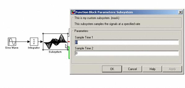
44 40 Subsystems The Mask Editor allows you to change how the subsystem should look, e.g., the subsystem icon. Set Parameters for the subsystem: Double click on the sub system now gives the Parameter window for the subsystem:
45 41 Subsystems

46 9 Model Explorer The Model Explorer allows you to quickly locate, view, and change elements of a Simulink model or Stateflow chart. To display the Model Explorer, select Model Explorer from the Simulink View menu. 42
47 10 Exercises In this chapter we provide more exercises. Exercise: Build the following block diagram: In this exercise we will model a rubber ball that is thrown in the air with an initial velocity of 15 m/s from a height of 10 m. We will model the dynamics of the ball as it bounces, under the influence of gravity. We will assume that 20% of the energy is lost on each bounce. (That is, after each impact, the ball will travel at 80% of its prior velocity, but in the opposite direction.) We can model this example by integrating g (g = -9.81m/s^2) over time with the initial condition set to 15 m/s. We reset the integrator each time the position reaches zero meters and set the new initial condition to -80% of the impact velocity. Position is modeled by integrating the velocity over time with the initial condition set to 10m/s. The result should be: 43

48 44 Subsystems Watch this video to see the result: ding.html


49 Hans-Petter Halvorsen, M.Sc. Blog: University College of Southeast Norway
MATLAB Examples. Simulink. Hans-Petter Halvorsen, M.Sc.
 MATLAB Examples Simulink Hans-Petter Halvorsen, M.Sc. What is Simulink? Simulink is an add-on to MATLAB. You need to have MATLAB in order to use Simulink Simulink is used for Simulation of dynamic models
Introduction to Simulink. The Use of Mathematic Simulations in Electrical Engineering
 Introduction to Simulink The Use of Mathematic Simulations in Electrical Engineering Lecture Outline 1) Introduction to Simulink 2) Modelling of dynamics systems 2 Simulink Tool for modeling, simulating,
University College of Southeast Norway MATLAB. Part III: Simulink and Advanced Topics. Hans-Petter Halvorsen,
 University College of Southeast Norway MATLAB Part III: Simulink and Advanced Topics Hans-Petter Halvorsen, 2017.06.19 http://www.halvorsen.blog Preface Copyright You cannot distribute or copy this document
Experiment 8 SIMULINK
 Experiment 8 SIMULINK Simulink Introduction to simulink SIMULINK is an interactive environment for modeling, analyzing, and simulating a wide variety of dynamic systems. SIMULINK provides a graphical user
Experiment 6 SIMULINK
 Experiment 6 SIMULINK Simulink Introduction to simulink SIMULINK is an interactive environment for modeling, analyzing, and simulating a wide variety of dynamic systems. SIMULINK provides a graphical user
Tutorial: Getting Started with the LabVIEW Simulation Module
 Tutorial: Getting Started with the LabVIEW Simulation Module - LabVIEW 8.5 Simulati... Page 1 of 10 Cart Help Search You are here: NI Home > Support > Product Reference > Manuals > LabVIEW 8.5 Simulation
Introduction to Matlab Simulink. Control Systems
 Introduction to Matlab Simulink & their application in Control Systems ENTC 462 - Spring 2007 Introduction Simulink (Simulation and Link) is an extension of MATLAB by Mathworks Inc. It works with MATLAB
Modeling Mechanical System using SIMULINK
 Modeling Mechanical System using SIMULINK Mechanical System We will consider a toy train consisting of an engine and a car as shown in Figure. Assuming that the train only travels in one direction, we
Example: Modeling a Cruise Control System in Simulink
 Example: Modeling a Cruise Control System in Simulink Physical setup and system equations Building the model Open-loop response Extracting the Model Implementing PI control Closed-loop response Physical
SIMULINK A Tutorial by Tom Nguyen
 Introduction SIMULINK A Tutorial by Tom Nguyen Simulink (Simulation and Link) is an extension of MATLAB by Mathworks Inc. It works with MATLAB to offer modeling, simulating, and analyzing of dynamical
Simulation in LabVIEW. Hans-Petter Halvorsen, M.Sc.
 Simulation in LabVIEW Hans-Petter Halvorsen, M.Sc. Software LabVIEW LabVIEW Control Design and Simulation Module This module is used for creating Control and Simulation applications with LabVIEW. Here
Control and Simulation in. LabVIEW
 Telemark University College Department of Electrical Engineering, Information Technology and Cybernetics Solutions Control and Simulation in HANS-PETTER HALVORSEN, 2011.08.11 LabVIEW Faculty of Technology,
[ MATLAB ] [ Resources ] PART TWO: SIMULINK
![[ MATLAB ] [ Resources ] PART TWO: SIMULINK](/thumbs/82/85270175.jpg "[ MATLAB ] [ Resources ] PART TWO: SIMULINK") Página 1 de 15 [ MATLAB ] [ Resources ] PART TWO: SIMULINK Contents Introduction Getting Started Handling of Blocks and Lines Annotations Some Examples NOTE: This tutorial is based on Simulink Version
Página 1 de 15 [ MATLAB ] [ Resources ] PART TWO: SIMULINK Contents Introduction Getting Started Handling of Blocks and Lines Annotations Some Examples NOTE: This tutorial is based on Simulink Version
SIMULINK Tutorial. Select File-New-Model from the menu bar of this window. The following window should now appear.
 SIMULINK Tutorial Simulink is a block-orientated program that allows the simulation of dynamic systems in a block diagram format whether they are linear or nonlinear, in continuous or discrete forms. To
Session 3 Introduction to SIMULINK
 Session 3 Introduction to SIMULINK Brian Daku Department of Electrical Engineering University of Saskatchewan email: daku@engr.usask.ca EE 290 Brian Daku Outline This section covers some basic concepts
Lecture 10: Simulink. What is Simulink?
 Lecture 10: Simulink Dr. Mohammed Hawa Electrical Engineering Department University of Jordan EE201: Computer Applications. See Textbook Chapter 10. What is Simulink? Simulink is a tool for modeling, simulating
Experiment 3. Getting Start with Simulink
 Experiment 3 Getting Start with Simulink Objectives : By the end of this experiment, the student should be able to: 1. Build and simulate simple system model using Simulink 2. Use Simulink test and measurement
SIGNALS AND LINEAR SYSTEMS LABORATORY EELE
 The Islamic University of Gaza Faculty of Engineering Electrical Engineering Department SIGNALS AND LINEAR SYSTEMS LABORATORY EELE 3110 Experiment (5): Simulink Prepared by: Eng. Mohammed S. Abuwarda Eng.
UNIT 5. Simulink. 1. Introduction
 UNIT 5 Simulink 1. Introduction... 1 2. Simulink... 2 2.1 Starting Simulink... 2 2.2 Model building... 3 2.3 Simulation parameters and Scope block... 5 2.4 Subsystems and masks... 11 2.5 S Functions...
Exercise: State-space models
 University College of Southeast Norway Exercise: State-space models A state-space model is a structured form or representation of a set of differential equations. Statespace models are very useful in Control
University College of Southeast Norway. Control and Simulation. in LabVIEW. Hans-Petter Halvorsen,
 University College of Southeast Norway Control and Simulation Hans-Petter Halvorsen, 2016.10.28 in LabVIEW http://home.hit.no/~hansha Preface This document explains the basic concepts of using LabVIEW
Objectives. Simulink Basics
 Simulink Basics This material exempt per Department of Commerce license exception TSU Objectives After completing this module, you will be able to: Describe Simulink environment List some of the commonly
Process Automation CHEM-E7140
 Process Automation CHEM-E7140 Tutorial 3: An introduction to Simulink 1 Contents 1 Simulink: a brief introduction...2 A. Getting started...2 B. Modeling dynamic models...3 C. Creating a new model...4 D.
INTRODUCTION TO MATLAB, SIMULINK, AND THE COMMUNICATION TOOLBOX
 INTRODUCTION TO MATLAB, SIMULINK, AND THE COMMUNICATION TOOLBOX 1) Objective The objective of this lab is to review how to access Matlab, Simulink, and the Communications Toolbox, and to become familiar
BME 5742 Bio-Systems Modeling and Control
 BME 5742 Bio-Systems Modeling and Control Lecture 4 Simulink Tutorial 1: Simulation of the Malthusian and Logistic Models Model Set Up, Scope Set Up Dr. Zvi Roth (FAU) 1 Getting started In the MATLAB command
Computer Aided Design (CAD) Lecture 10. Introduction to Simulink (3) Dr.Eng. Basem ElHalawany
 Lecture 10. Introduction to Simulink (3) Dr.Eng. Basem ElHalawany") Computer Aided Design (CAD) Lecture 10 Introduction to Simulink (3) Dr.Eng. Basem ElHalawany Schedule (Updated 28-10) Topics Estimated Duration (# Lectures) Introduction 1 Introduction to Matlab Environment
Computer Aided Design (CAD) Lecture 10 Introduction to Simulink (3) Dr.Eng. Basem ElHalawany Schedule (Updated 28-10) Topics Estimated Duration (# Lectures) Introduction 1 Introduction to Matlab Environment
SIMULINK FOR BEGINNERS:
 1 SIMULINK FOR BEGINNERS: To begin your SIMULINK session open first MATLAB ICON by clicking mouse twice and then type»simulink You will now see the Simulink block library. 2 Browse through block libraries.
Mathematical Modelling Using SimScape (Mechanical Systems)
") Experiment Three Mathematical Modelling Using SimScape (Mechanical Systems) Control Systems Laboratory Dr. Zaer Abo Hammour Dr. Zaer Abo Hammour Control Systems Laboratory 1. Translational Mechanical System
Experiment Three Mathematical Modelling Using SimScape (Mechanical Systems) Control Systems Laboratory Dr. Zaer Abo Hammour Dr. Zaer Abo Hammour Control Systems Laboratory 1. Translational Mechanical System
2. Motion Analysis - Sim-Mechanics
 2 Motion Analysis - Sim-Mechanics Figure 1 - The RR manipulator frames The following table tabulates the summary of different types of analysis that is performed for the RR manipulator introduced in the
Systems & Control Lab.-Manual
 German University in Cairo - GUC Information Engineering and Technology Electronics, Communications, & Networks Systems & Control Lab.-Manual (3) A brief overview of: By: Eng. Moustafa Adly ON-OFF control
DAQ in MATLAB HANS-PETTER HALVORSEN,
 Telemark University College Department of Electrical Engineering, Information Technology and Cybernetics DAQ in MATLAB HANS-PETTER HALVORSEN, 2011.06.07 Faculty of Technology, Postboks 203, Kjølnes ring
2 SIMULATING A MODEL Simulink Tutorial
 2 SIMULATING A MODEL Simulink Tutorial 1 Introduction Simulation of dynamic systems has been proven to be immensely useful in system modeling and controller design. Simulink R is a add-on to MATLAB which
UNIVERSITI TEKNIKAL MALAYSIA MELAKA FAKULTI KEJURUTERAAN ELEKTRONIK DAN KEJURUTERAAN KOMPUTER
 UNIVERSITI TEKNIKAL MALAYSIA MELAKA FAKULTI KEJURUTERAAN ELEKTRONIK DAN KEJURUTERAAN KOMPUTER FAKULTI KEJURUTERAAN ELEKTRONIK DAN KEJURUTERAAN KOMPUTER BENC 2113 DENC ECADD 2532 ECADD LAB SESSION 6/7 LAB
MATLAB AND SIMULINK. Modeling Dynamic Systems J. ABELL
 MATLAB AND SIMULINK Modeling Dynamic Systems J. ABELL Modeling Dynamic Systems Creating a Model Create an Empty Model Create a Model Template Populate a Model Copy Blocks to Your Model Browse Block Libraries
MATLAB Examples. Flow Control and Loops. Hans-Petter Halvorsen, M.Sc.
 MATLAB Examples Flow Control and Loops Hans-Petter Halvorsen, M.Sc. Flow Control and Loops in MATLAB Flow Control: if-elseif-else statement switch-case-otherwise statement Loops: for Loop while Loop The
the Simulation of Dynamics Using Simulink
 INTRODUCTION TO the Simulation of Dynamics Using Simulink Michael A. Gray CRC Press Taylor & Francis Croup Boca Raton London New York CRC Press is an imprint of the Taylor & Francis Group an informa business
Introduction to ERwin
 Introduction to ERwin Database Design & Modelling Hans-Petter Halvorsen, M.Sc. Software The following Editions can be downloaded for Free on Internet: CA ERwin Data Modeler Community Edition SQL Server
Tutorial 17 Workflow Graphical User Interface Figure 1
 Tutorial 17 Getting Started with Modelica Objective This tutorial gives an introduction to, explaining the first steps from opening existing models and packages to modeling including result interpretation.
Lab 2 Modeling from an observed response
 Lab 2 Modeling from an observed response Agenda Time Item 5 min Lab introduction The big picture of system modeling in the time domain 5 min The SEE, to quantify the goodness of fit 5 min Demonstration
Tutorial - Exporting Models to Simulink
 Tutorial - Exporting Models to Simulink Introduction The Matlab and Simulink tools are widely used for modeling and simulation, especially the fields of control and system engineering. This tutorial will
What Is SimMechanics?
 SimMechanics 1 simulink What Is Simulink? Simulink is a tool for simulating dynamic systems with a graphical interface specially developed for this purpose. Physical Modeling runs within the Simulink environment
Create a Virtual Test Environment
 Create a Virtual Test Environment Step by Step Exercises Hans-Petter Halvorsen, M.Sc. Why Do We Need a Test Environment? Why cant we just use our own PC? Why Test Environment? It works on my PC says the
Assignment 2 in Simulation of Telesystems Laboratory exercise: Introduction to Simulink and Communications Blockset
 Mid Sweden University Revised: 2013-11-12 Magnus Eriksson Assignment 2 in Simulation of Telesystems Laboratory exercise: Introduction to Simulink and Communications Blockset You are expected to conclude
What is Simulink. >>simulink
 MATLAB Simulink What is Simulink Simulink is an input/output device GUI block diagram simulator. Simulink contains a Library Editor of tools from which we can build input/output devices and continuous
2018, Controllab Products B.V. Author: Ir. C. Kleijn, Ir. M. A. Groothuis. Disclaimer
 2018, Controllab Products B.V. Author: Ir. C. Kleijn, Ir. M. A. Groothuis Disclaimer This manual describes the modeling and simulation package 20-sim. C ontrollab Products B.V. makes every effort to insure
ROSE-HULMAN INSTITUTE OF TECHNOLOGY
 Introduction to Working Model Welcome to Working Model! What is Working Model? It's an advanced 2-dimensional motion simulation package with sophisticated editing capabilities. It allows you to build and
Visual Studio Team Services
 Visual Studio Team Services Getting Started Hans-Petter Halvorsen, M.Sc. Visual Studio Team Services Visual Studio Team Services is a platform taking care of all aspects of the process of developing software
Software Implementation
 Software Implementation Quiz with Explainations Hans-Petter Halvorsen, M.Sc. Questions 1. List 10 different Programming Languages 2. What is an IDE? - Give some Examples 3. What is.net? 4. What is ASP.NET?
Simulink Basics Tutorial
 1 of 20 1/11/2011 5:45 PM Starting Simulink Model Files Basic Elements Running Simulations Building Systems Simulink Basics Tutorial Simulink is a graphical extension to MATLAB for modeling and simulation
Datalogging in LabVIEW
 Telemark University College Department of Electrical Engineering, Information Technology and Cybernetics Datalogging in LabVIEW HANS-PETTER HALVORSEN, 2011.01.04 Faculty of Technology, Postboks 203, Kjølnes
ME422 Mechanical Control Systems Matlab/Simulink Hints and Tips
 Cal Poly San Luis Obispo Mechanical Engineering ME Mechanical Control Systems Matlab/Simulink Hints and Tips Ridgely/Owen, last update Jan Building A Model The way in which we construct models for analyzing
University College of Southeast Norway. LM-900 Level Tank. Hans-Petter Halvorsen,
 University College of Southeast Norway LM-900 Level Tank Hans-Petter Halvorsen, 2016.10.26 http://home.hit.no/~hansha Table of Contents Table of Contents... ii 1 Introduction... 1 2 System Description...
Virtual Instruments with LabVIEW
 Telemark University College Department of Electrical Engineering, Information Technology and Cybernetics Virtual Instruments with LabVIEW HANS-PETTER HALVORSEN, 2011.01.04 Faculty of Technology, Postboks
Introduction to Simulink
 Introduction to Simulink by Vinay S. K. Guntu 4310 Feedback Control Systems 1 Simulink Basics Tutorial Simulink is a graphical extension to MATLAB for modeling and simulation of systems. Advantages 1)
Solutions. Discretization HANS-PETTER HALVORSEN,
 Telemark University College Department of Electrical Engineering, Information Technology and Cybernetics Solutions HANS-PETTER HALVORSEN, 2011.08.12 Discretization Faculty of Technology, Postboks 203,
= 3 + (5*4) + (1/2)*(4/2)^2.
 + (1/2)*(4/2)^2.") Physics 100 Lab 1: Use of a Spreadsheet to Analyze Data by Kenneth Hahn and Michael Goggin In this lab you will learn how to enter data into a spreadsheet and to manipulate the data in meaningful ways.
Physics 100 Lab 1: Use of a Spreadsheet to Analyze Data by Kenneth Hahn and Michael Goggin In this lab you will learn how to enter data into a spreadsheet and to manipulate the data in meaningful ways.
Introduction to Simulink
 Introduction to Simulink There are several computer packages for finding solutions of differential equations, such as Maple, Mathematica, Maxima, MATLAB, etc. These systems provide both symbolic and numeric
Data Acquisition HANS-PETTER HALVORSEN,
 Telemark University College Department of Electrical Engineering, Information Technology and Cybernetics Data Acquisition HANS-PETTER HALVORSEN, 2011.10.14 Faculty of Technology, Postboks 203, Kjølnes
Working Model. The world s most popular 2D computer aided engineering tool
 Working Model 2D The world s most popular 2D computer aided engineering tool Use automatic collision detection and friction to accurately model real-life mechanical systems Track the motion of an object
What s New in MATLAB and Simulink
 What s New in MATLAB Simulink Fabrizio Sara 2015 The MathWorks, Inc. 1 Engineers scientists 2 Engineers scientists Develop algorithms Analyze data write MATLAB code. 3 Engineers scientists deploy algorithms
Contents 10. Graphs of Trigonometric Functions
 Contents 10. Graphs of Trigonometric Functions 2 10.2 Sine and Cosine Curves: Horizontal and Vertical Displacement...... 2 Example 10.15............................... 2 10.3 Composite Sine and Cosine
Simulink Basics Tutorial
 Simulink Basics Tutorial Simulink is a graphical extension to MATLAB for modeling and simulation of systems. One of the main advantages of Simulink is the ability to model a nonlinear system, which a transfer
Quick Start Guide for OP4200 Thank you for choosing RT-LAB as your real-time simulation platform.
 Quick Start Guide for OP4200 Thank you for choosing RT-LAB as your real-time simulation platform. This Quick Start Guide will guide you through the first steps in achieving real-time and closed-loop simulation,
ES205 Analysis and Design of Engineering Systems: Lab 1: An Introductory Tutorial: Getting Started with SIMULINK
 ES05 Analyi and Deign of Engineering Sytem: Lab : An Introductory Tutorial: Getting Started with SIMULINK What i SIMULINK? SIMULINK i a oftware package for modeling, imulating, and analyzing dynamic ytem.
HW #7 Solution Due Thursday, November 14, 2002
 12.010 HW #7 Solution Due Thursday, November 14, 2002 Question (1): (10-points) Repeat question 1 of HW 2 but this time using Matlab. Attach M-file and output. Write, compile and run a fortran program
8438/8838 User Manual User Manual of the 8438/8838 MATLAB Embedded Controllers
 User Manual of the 8438/8838 MATLAB Embedded Controllers Warranty All products manufactured by ICP DAS are warranted against defective materials for a period of one year from the date of delivery to the
Introduction to Simulink. Todd Atkins
 Introduction to Simulink Todd Atkins tatkins@mathworks.com 1 Outline What is Simulink? Working with Simulink How Simulink works Componentizing models Continuous and discrete models 4 Simulink Applications
solidthinking Design Release Notes
 solidthinking Design 2017.2 Release Notes The solidthinking Design package includes Inspire and Evolve 2017.2. Inspire is available on Windows, while Evolve is available on Windows and Mac. solidthinking
Physics 251 Laboratory Introduction to Spreadsheets
 Physics 251 Laboratory Introduction to Spreadsheets Pre-Lab: Please do the lab-prep exercises on the web. Introduction Spreadsheets have a wide variety of uses in both the business and academic worlds.
MapleSim User's Guide
 MapleSim User's Guide Copyright Maplesoft, a division of Waterloo Maple Inc. 2001-2009 MapleSim User's Guide Copyright Maplesoft, MapleSim, and Maple are all trademarks of Waterloo Maple Inc. Maplesoft,
Matlab Simulink Simscape
 Matlab Simulink Simscape 1 / 6 2 / 6 3 / 6 Matlab Simulink Simscape Simscape enables you to rapidly create models of physical systems within the Simulink environment. With Simscape, you build physical
Ball Toss. Data Pro program. 2. Make a sketch of your prediction for the velocity vs. time graph. Describe in words what this graph means.
 Ball Toss Experiment 34 When a juggler tosses a ball straight upward, the ball slows down until it reaches the top of its path. The ball then speeds up on its way back down. A graph of its velocity vs.
Importing Models from Physical Modeling. Tools Using the FMI Standard
 Importing Models from Physical Modeling Tools Using the FMI Standard Overview The objective of this tutorial is to demonstrate the workflow for the integration of FMUs in DYNA4. The following use case
Running 2D Ball Balancer Experiment
 Running 2D Ball Balancer Experiment Contents Purpose...1 Physical Setup...1 Procedures...3 Step 1: Calibration...3 Step 2: MATLAB and the Environment...4 Step 3: Setup File...5 Step 4: Compile and Run...5
MathWorks Technology Session at GE Physical System Modeling with Simulink / Simscape
 SimPowerSystems SimMechanics SimHydraulics SimDriveline SimElectronics MathWorks Technology Session at GE Physical System Modeling with Simulink / Simscape Simscape MATLAB, Simulink September 13, 2012
Precalculus 2 Section 10.6 Parametric Equations
 Precalculus 2 Section 10.6 Parametric Equations Parametric Equations Write parametric equations. Graph parametric equations. Determine an equivalent rectangular equation for parametric equations. Determine
Mass-Spring Systems. Last Time?
 Mass-Spring Systems Last Time? Implicit Surfaces & Marching Cubes/Tetras Collision Detection & Conservative Bounding Regions Spatial Acceleration Data Structures Octree, k-d tree, BSF tree 1 Today Particle
Database Views & Stored Procedures. Hans-Petter Halvorsen, M.Sc.
 Database Views & Stored Procedures Hans-Petter Halvorsen, M.Sc. SQL Server Hans-Petter Halvorsen, M.Sc. Microsoft SQL Server 3 1 2 Your SQL Server Your Tables Your Database 4 Write your Query here 5 The
Hands-on Lab. LabVIEW Simulation Tool Kit
 Hands-on Lab LabVIEW Simulation Tool Kit The LabVIEW Simulation Tool Kit features a comprehensive suite of tools to test designs. This lab provides a primer to implementing a simulation. This will be useful
MATLAB Examples. Interpolation and Curve Fitting. Hans-Petter Halvorsen
 MATLAB Examples Interpolation and Curve Fitting Hans-Petter Halvorsen Interpolation Interpolation is used to estimate data points between two known points. The most common interpolation technique is Linear
MODELING IN SCILAB: PAY ATTENTION TO THE RIGHT
 powered by MODELING IN SCILAB: PAY ATTENTION TO THE RIGHT APPROACH PART 2 In this tutorial we show how to model a physical system described by ODE using Xcos environment. The same model solution is also
Exploring Projectile Motion with Interactive Physics
 Purpose: The purpose of this lab will is to simulate a laboratory exercise using a program known as "Interactive Physics." Such simulations are becoming increasingly common, as they allow dynamic models
FMI Kit for Simulink version by Dassault Systèmes
 FMI Kit for Simulink version 2.4.0 by Dassault Systèmes April 2017 The information in this document is subject to change without notice. Copyright 1992-2017 by Dassault Systèmes AB. All rights reserved.
UNIVERSITI TEKNIKAL MALAYSIA MELAKA FAKULTI KEJURUTERAAN ELEKTRONIK DAN KEJURUTERAAN KOMPUTER
 UNIVERSITI TEKNIKAL MALAYSIA MELAKA FAKULTI KEJURUTERAAN ELEKTRONIK DAN KEJURUTERAAN KOMPUTER FAKULTI KEJURUTERAAN ELEKTRONIK DAN KEJURUTERAAN KOMPUTER BENC 2113 DENC ECADD 2532 ECADD LAB SESSION 6/7 LAB
Lab 6 : Introduction to Simulink, Link for CCS & Real-Time Workshop
 Lab 6 : Introduction to Simulink, Link for CCS & Real-Time Workshop September, 2006 1 Overview The purpose of this lab is to familiarize you with Simulink, Real Time Workshop, Link for CCS and how they
Working with the Dope Sheet Editor to speed up animation and reverse time.
 Bouncing a Ball Page 1 of 2 Tutorial Bouncing a Ball A bouncing ball is a common first project for new animators. This classic example is an excellent tool for explaining basic animation processes in 3ds
AUDIO WEAVER DESIGNER USERS GUIDE
 AUDIO WEAVER DESIGNER USERS GUIDE August 2016 Copyright Information 2016-2017 DSP Concepts, Inc., ALL RIGHTS RESERVED. This document may not be reproduced in any form without prior, express written consent
Rotary Motion Servo Plant: SRV02. Rotary Experiment #00: QuaRC Integration. Using SRV02 with QuaRC. Student Manual
 Rotary Motion Servo Plant: SRV02 Rotary Experiment #00: QuaRC Integration Using SRV02 with QuaRC Student Manual SRV02 QuaRC Integration Instructor Manual Table of Contents 1. INTRODUCTION...1 2. PREREQUISITES...1
Math 4: Advanced Algebra Ms. Sheppard-Brick A Quiz Review LT ,
 4A Quiz Review LT 3.4 3.10, 4.1 4.3 Key Facts Know how to use the formulas for projectile motion. The formulas will be given to you on the quiz, but you ll need to know what the variables stand for Horizontal:
University College of Southeast Norway ASP.NET. Web Programming. Hans-Petter Halvorsen,
 University College of Southeast Norway Hans-Petter Halvorsen, 2016.11.01 ASP.NET Web Programming http://home.hit.no/~hansha Table of Contents 1 Introduction... 4 1.1 Visual Studio... 4 1.2 C#... 5 1.3.NET
Embedded Systems. Problem 1: Getting started with STATEFLOW. Starting STATEFLOW
 Prof. Bernd Finkbeiner, Ph.D. Winter term 2008/2009 Dipl.-Inf. Rüdiger Ehlers Problem Set 2 Dipl.-Inf.Hans-Jörg Peter Due: Thursday,6 th November 2008 Michael Gerke, B.Sc. Embedded Systems STATEFLOW is
Inlichtingenblad, matlab- en simulink handleiding en practicumopgaven IWS
 Inlichtingenblad, matlab- en simulink handleiding en practicumopgaven IWS 4 SIMULINK 4 Simulink 4 Quick introduction General information Simulink is an etension of Matlab software for simulating dynamic
An Introduction to Using Simulink
 An Introduction to Using Simulink COURSE NOTES Eric Peasley, Department of Engineering Science, University of Oxford Adapted and updated by Dr I. F. Mear using MATLAB 2017b and MATLAB 2018b version 5.0,
Reset Cursor Tool Clicking on the Reset Cursor tool will clear all map and tool selections and allow tooltips to be displayed.
 SMS Featured Icons: Mapping Toolbar This document includes a brief description of some of the most commonly used tools in the SMS Desktop Software map window toolbar as well as shows you the toolbar shortcuts
Comparative Analysis Of Vehicle Suspension System in Matlab-SIMULINK and MSc- ADAMS with the help of Quarter Car Model
 Comparative Analysis Of Vehicle Suspension System in Matlab-SIMULINK and MSc- ADAMS with the help of Quarter Car Model S. J. Chikhale 1, Dr. S. P. Deshmukh 2 PG student, Dept. of Mechanical Engineering,
Mechanical System and SimMechanics Simulation
 American Journal of Mechanical Engineering, 3, Vol., No. 7, 555 Available online at http://pubs.sciepub.com/ajme//7/ Science and Education Publishing DOI:.69/ajme--7 Mechanical System and SimMechanics
Quick Start Guide. Thank you for choosing RT-LAB as your real-time simulation platform.
 Quick Start Guide Thank you for choosing RT-LAB as your real-time simulation platform. This Quick Start Guide will guide you through the first steps in achieving real-time and closed-loop simulation, while
Engine with Propeller Tutorial (Professional)
") Engine with Propeller Tutorial (Professional) Copyright 2017 FunctionBay, Inc. All rights reserved. User and training documentation from FunctionBay, Inc. is subjected to the copyright laws of the Republic
Engine with Propeller Tutorial (Professional) Copyright 2017 FunctionBay, Inc. All rights reserved. User and training documentation from FunctionBay, Inc. is subjected to the copyright laws of the Republic
Date Course Name Instructor Name Student(s) Name WHERE WILL IT LAND?
 Name WHERE WILL IT LAND?") Date Course Name Instructor Name Student(s) Name WHERE WILL IT LAND? You have watched a ball roll off a table and strike the floor. What determines where it will land? Could you predict where it will land?
Date Course Name Instructor Name Student(s) Name WHERE WILL IT LAND? You have watched a ball roll off a table and strike the floor. What determines where it will land? Could you predict where it will land?
Cloth Simulation. Tanja Munz. Master of Science Computer Animation and Visual Effects. CGI Techniques Report
 Cloth Simulation CGI Techniques Report Tanja Munz Master of Science Computer Animation and Visual Effects 21st November, 2014 Abstract Cloth simulation is a wide and popular area of research. First papers