LabVIEW -VI MCC. Virtual Instruments for MCC Control Units. Manual 1253-A001 GB
|
|
|
- Samantha Griffith
- 5 years ago
- Views:
Transcription

1 LabVIEW -VI MCC Virtual Instruments for MCC Control Units Manual 1253-A001 GB
2
3 phytron LabVIEW Virtual Instruments for MCC Control Units TRANSLATION OF THE GERMAN ORIGINAL MANUAL 6/2010 Manual MA 1253-A001 GB
4 Manual LabVIEW -VI MCC 2010 All rights with: Phytron GmbH Industriestraße Gröbenzell, Germany Tel.: /503-0 Fax: / Every possible care has been taken to ensure the accuracy of this technical manual. All information contained in this manual is correct to the best of our knowledge and belief but cannot be guaranteed. Furthermore we reserve the right to make improvements and enhancements to the manual and / or the devices described herein without prior notification. You find the updated version of this manual on the website of We appreciate suggestions and criticisms for further improvement. Please send your comments to the following address: doku@phytron.de MA 1253-A001 GB 4
5 phytron Contents 1 What is LabVIEW? Requirements Extent of Supply To Consider Before Installation Qualified Personnel Warning Regarding Use of Software Products General VI Description Description of the MCC.llb General AD-MCC.VI COMM-MCC.vi Counter-MCC.vi Directmode-MCC.vi Drive-MCC.vi Encoder-MCC.vi Init-MCC.vi Input-MCC.vi Output-MCC.vi Parameter-MCC.vi Register-MCC.vi Status-MCC.vi Demo-MCC.vi General Description A/D Inputs and Encoder Timer Reading Application for Direct Mode and Motor Driving Internal Distance Counter Reading and Displaying The MCC Inputs / Outputs Reading / Setting Parameters Reading / Writing Register Reading and Writing Initiator and Controller Status Reading Parameters Copyright and Disclaimer of Warranty Index MA 1253-A001 GB
6 Manual LabVIEW -VI MCC 1 What is LabVIEW? This manual describes the LabVIEW graphical programming language from National Instruments, which uses icons to create the application. LabVIEW stands for Laboratory Virtual Instrument Engineering Workbench. LabVIEW programs are called Virtual Instruments or VIs. These VIs content the front panel, the user interface and the block diagram. The block diagram is a graphical program code, which is compiled like other high level programming languages. This manual describes the LabVIEW use for the Phytron controllers MCC-1, MCC-2 and MCC-2 LIN. LabVIEW is a Trademark of National Instruments Corporation. See chap Requirements A well-trained LabVIEW user is expected for using the Phytron MCC controller VIs. He knows the programming environment. Basic knowledge in programming like data types, loops etc. are required. The MCC VIs are built for LabVIEW 8.0 or higher. 1.2 Extent of Supply The package contents two LabVIEW libraries: MCC.llb Encloses the VIs to be applied for the MCC controllers Demo-MCC.llb Demo-applications which make the VIs clear MA 1253-A001 GB 6
7 phytron 2 To Consider Before Installation Read all manuals very carefully before installing and operating. Observe the safety instructions in the following chapter! 2.1 Qualified Personnel Design, installation and operation of systems may only be performed by qualified and trained personnel. These persons should be able to recognize and handle risks emerging from electrical, mechanical or electronic system parts. The qualified personnel must know the content of this manual and be able to understand all documents belonging to the product. Safety instructions are to be planned. The trained personnel must know all valid standards, regulations and rules for the accident prevention, which are necessary for working with the product. WARNING Without proper training and qualifications damages to devices and injury might result! 2.2 Warning Regarding Use of Software Products 1. In any application the reliability of operation of the software products can be impaired by adverse factors, e. g. differences in electrical power supply or, computer hardware malfunctions. To avoid damage by system failures the user must take appropriate safety measures, including back-up or shut down mechanism. 2. Malfunctions are possible while programming the instruction codes e. g. sudden run of a connected motor, braking etc. Please test the program flow step by step! 3. Each end user system is customized and differs from the testing platform. Therefore the user or application designer is responsible for verifying and validating the suitability of the application. 7 MA 1253-A001 GB
8 Manual LabVIEW -VI MCC 3 General VI Description LabVIEW programs are called virtual instruments or VIs. Every VI can be used as a stand-alone program or as a subroutine called sub VI. The user defines the data flow by connecting the VIs with connection lines (wires). The VI executes when all input data are available. If the complete VI is finished, the results will be on the outputs. The sequence of the execution is defined by the dependency of the data. There is no predefined sequence (e. g. from right to left). MA 1253-A001 GB 8
9 phytron 4 Description of the MCC.llb 4.1 General Inputs and outputs which are the same for all VIs in the library: Name I/O Meaning VISA resource name in Input Transfer of the interface parameters Error in Input Input of the error clusters VISA resource name out Output Display of the interface parameters Error out Output Output of the error cluster Inputs and outputs have the same function. They are only described once. A cluster is the bundling of different data types in LabVIEW. It can be used as an input or output. 4.2 AD-MCC.VI Read the A/D value of the MCC. This VI provides the current A/D converter value as a 16-bit unit to the output while executing. Fig. 1: AD-MCC.vi Name I/O Meaning Address Input Adjusted address at the controller ( bit unit) Channel Input Channel of the A/D converter, which should be read (1 or 2, 8-bit unit) A/D Value Output A/D value in increments (0 1023, 10-bit) 9 MA 1253-A001 GB
10 Manual LabVIEW -VI MCC 4.3 COMM-MCC.vi This VI is internal used by other VIs. It should not be applied for programming user specific applications. 4.4 Counter-MCC.vi This VI reads the selected axis counter. It displays the counter value of the selected axis by reading the parameter 20 (P20). You ll find the parameter description in chapter 6. Fig. 2: Counter-MCC.vi Name I/O Meaning Address Input Adjusted address at the controller ( bit unit) Axis Input The counter of the axis should be read (1 or 2, 8-bit unit) Counter Value Output Counter value of the axis (Double) MA 1253-A001 GB 10
11 phytron 4.5 Directmode-MCC.vi An instruction is transmitted to the controller. The VI transmits the string at the input Send String to the controller and picks up the answer from the controller. For detailed description of the controller commands see chap.6. Fig. 3: Directmode-MCC.vi Name I/O Meaning Address Input Adjusted address at the controller ( bit unit) Send String Input Command, which is transmitted to the controller (e. g. X+1000 corresponds to drive 1000 steps) Transmission OK Output True, if the controller acknowledged the command (ACK) False, if the command was invalid (NAK) Receive String Output Answer string of the controller (without control character and ACK) It s empty when the commands have no response. 11 MA 1253-A001 GB
12 Manual LabVIEW -VI MCC 4.6 Drive-MCC.vi This VI sends drive instructions to the MCC. This functional module reads the values adjusted in the cluster and generates a drive instruction for the MCC. Fig. 4: Drive-MCC.vi Name I/O Meaning Cluster: Axis Address Position Mode Distance Input It has the following data types: Axis (8-bit unit): axis, where the drive instruction is displayed (1 or 2) Address (8-bit unit): Controller address (0-15) Position Mode (ENUM): the following adjustments are available: o Relative, generates and transmits a relative drive instruction o Absolute, generates and transmits an absolute drive instruction o Initialization Plus, generates and transmits an initialization toward the positive direction o Initialization Minus, generates and transmits an initialization toward the negative direction o Free Run Plus, starts a free run toward the positive direction o Free Run Minus, starts a free run toward the negative direction Distance (DLB): this input is used as a distance for relative and absolute drive instructions Transmission OK Output True: the controller accepts the instruction False: invalid command MA 1253-A001 GB 12
13 phytron 4.7 Encoder-MCC.vi The encoder counter reads the selected axis. Parameter 22 (P22) is read out for the corresponding axis. You ll find the description of the parameters in chapter 6 parameters. Fig. 5: Encoder-MCC.vi Name I/O Meaning Address Input Adjusted address at the controller ( bit unit) Axis Input The count of the axis is to be read (1 or 2, 8-bit unit) Encoder Value Output Read Encoder value of the axis (Double) 13 MA 1253-A001 GB
14 Manual LabVIEW -VI MCC 4.8 Init-MCC.vi This VI displays the initiator status. The MCC initiator status is imported and displayed as Boolean Cluster. Fig. 6: Init-MCC.vi Name I/O Meaning Address Input Adjusted address at the controller ( bit unit) Cluster: Initiator Status Output The Initiator Status consists of four elements (BOOL) Axis 1+, activated = TRUE, free = FALSE Axis 1-, activated = TRUE, free = FALSE Axis 2+, activated = TRUE, free = FALSE Axis 2 -, activated = TRUE, free = FALSE MA 1253-A001 GB 14
15 phytron 4.9 Input-MCC.vi Reads the MCC input status. The status of the MCC is displayed as a Boolean Cluster. Fig. 7: Input-MCC.vi Name I/O Meaning Address Input Adjusted address at the controller ( bit unit) Cluster: Inputs Output Inputs, consist of eight elements (Boolean) TRUE = Input High FALSE = Input Low 15 MA 1253-A001 GB
16 Manual LabVIEW -VI MCC 4.10 Output-MCC.vi This VI sets the outputs at the MCC. The status at the input is set as output status during execution. Fig. 8: Output-MCC.vi Name I/O Meaning Address Input Adjusted address at the controller ( bit unit) Cluster: Outputs Input Outputs, consist of eight elements (Boolean) TRUE = Output High FALSE = Output Low Transmission OK Output True: the controller accepts the instruction False: invalid command MA 1253-A001 GB 16
17 phytron 4.11 Parameter-MCC.vi This VI reads or sets the MCC parameters. The MCC reads or transmits the parameter which is adjusted in the Parameter Number. Fig. 9: Parameter-MCC.vi Name I/O Meaning Cluster: Address Axis Parameter Number Parameter Value Read / Write Input It has the following data types: Address (8-bit unit): controller address (0-15) Axis (8-bit unit): Axis, of which the parameter is read/written (1 or 2) Parameter Number (8-bit unit): Parameter number to be read or written Parameter Value (Double): Parameter value to be written. Only with the choice write! Read / Write (Enum): Contains the items Read and Write. Read: Parameter is read and is displayed at the Parameter Value output. Write: Parameter is written with the value from the Parameter Value input. Transmission OK Output True: the controller accepts the instruction False: invalid command(boolean) Parameter Value Output The Read function displays the parameter value of the selected parameter (Double). 17 MA 1253-A001 GB
18 Manual LabVIEW -VI MCC 4.12 Register-MCC.vi Reads or sets the MCC register. The register set in Register Number is read or transmitted to the MCC. Fig. 10: Register-MCC.vi Name I/O Meaning Cluster: Address Register Number Register Value Read / Write Input It has the following data types: Address (8-bit unit): controller address (0-15) Register Number (16-bit unit): Register number, to be read or written. Register Value (Double): Register value to be written. Only with the choice write! Read / Write (Enum): Contains the items Read and Write. Read: Parameter is read and is displayed at the Register Value output. Write: Parameter is written with the value from the Register Value input. Transmission OK Output True: the controller accepts the instruction False: invalid command (Boolean) Register Value Output The Read function displays the register value of the selected parameter (Double). MA 1253-A001 GB 18
19 phytron 4.13 Status-MCC.vi Reads the MCC status and displays the result as Boolean Cluster. Fig. 11: Status-MCC.vi Name I/O Meaning Address Input Adjusted address at the controller ( bit unit) Cluster: Status Output Displays the MCC status as Boolean cluster. The status is read binary. You ll find further information in the MINILOG Programming Manual for MCC available under the SB instruction. 19 MA 1253-A001 GB
 is equal in all demos and only described once.")
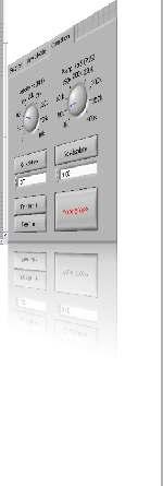
20 Manual LabVIEW -VI MCC 5 Demo-MCC.vi 5.1 General Description The VI demos use the VIs from the MCC.llb. These are demos of register cards with different tabs. The first register card (Settings) is equal in all demos and only described once. Settings of the register card: Here general settings for the interface are made: COM Port Address Configures the used interface. In this case the serial interface COM4. The Address adjusted at the controller Baud Rate Configuration of the controller s baud rate, e. g Timeout Error Stop The time waiting for an answer. If there is no answer in the specified time, VISA-VI outputs an error. This output displays an error message, which occurs during communication. Stops the program. MA 1253-A001 GB 20


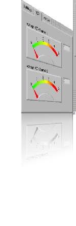
21 phytron 5.2 A/D Inputs and Encoder Timer Reading This demo has one register card with three tabs: Settings, A/D and Encoder. (For the description of Settings register card please see above.) A/D register card: This register card shows the present voltage at channel 1and 2 of the MCC A/D inputs. These are both graphically displayed as well as a number in the text box. Encoder register card: The MCC encoder counters and the counter value are imported and displayed in the text boxes. 21 MA 1253-A001 GB
 command")
22 Manual LabVIEW -VI MCC 5.3 Application for Direct Mode and Motor Driving This demo is a small application to demonstrate - Directmode-MCC.vi - Parameter-MCC.vi and - Drive-MCC.vi files. Direct Mode register card: Send String Send Receive String Input of the transmitting command Transfer of the command Display of the MCC answer Transmission OK Command recognized: LED on (ACK) command not recognized: LED off (NAK) MA 1253-A001 GB 22

23 phytron Operation register card: Velocity Hz (P14) Ramp Hz/S (P15) Go Relative Go Absolute Free Run + Free Run - Sets the driving speed of the MCC. Free Run + or enables to change the velocity also during the run. Sets the acceleration- and axes ramp. The value can only be transferred when the motor is at a standstill. Moves from the actual position by entered value (textbox). Moves the entered value (textbox) referred to the zero point.. Starts a free run toward positive direction Starts a free run toward negative direction! Motor STOP! Cancels each running positioning and stops the motor. 23 MA 1253-A001 GB
 Counter value display of axis 2 (Y) Deletes the graph Diagram of the varying")
24 Manual LabVIEW -VI MCC 5.4 Internal Distance Counter Reading and Displaying This demo reads the internal MCC distance counter (P20) and displays it as a counter value as well as a diagram. Counter register card: Counter Value Axis 1 Counter Value Axis 2 Reset XY Graph Counter value display of axis 1 (X) Counter value display of axis 2 (Y) Deletes the graph Diagram of the varying counter value at axis 1 and in the system of coordinates. MA 1253-A001 GB 24

25 phytron 5.5 The MCC Inputs / Outputs Reading / Setting This demo reads and displays the MCC inputs and activates the outputs. I/O register card: Inputs Outputs Display of the MCC input status: LED on = Status High LED off = Status Low The respective MCC outputs can be switched. 25 MA 1253-A001 GB
")
26 Manual LabVIEW -VI MCC 5.6 Parameters Reading / Writing This demo reads and writes the MCC parameters. Parameter register card: Read/Write Axis Reading or writing the parameters Axis, whose parameters are changed Parameter Number Parameter number, which is modified Parameter Value (Write Only) Parameter Value Value to which the parameter is changed (write only) Read parameter of the controller ( read only) MA 1253-A001 GB 26
 Register Value Reads or writes the registers Register number which is read or written Value that is")
27 phytron 5.7 Register Reading and Writing This demo reads and writes the MCC Register. Read/Write Registers register card: Read/Write Register Number Register Value (Write Only) Register Value Reads or writes the registers Register number which is read or written Value that is written in the register. (write only) Value that is written out of the register. (read only) 27 MA 1253-A001 GB

28 Manual LabVIEW -VI MCC 5.8 Initiator and Controller Status Reading This demo reads and displays the initiator status and the general MCC status. Status register card: Initiator Status Status Initiator status of the controller. The LED is on, when the initiator is activated. The SUI command is used. General status of the controller. The LEDs display the status. The SB command is used. The LED colors are described in the MiniLog Programming Manual. MA 1253-A001 GB 28
29 phytron 6 Parameters For operating a stepper motor controller different presettings as speed, acceleration ramps or waiting time are required which are called Parameters. Default parameters are stored at delivery which can be used in several applications. You can read and edit these parameters with LabVIEW Parameter-VI or MiniLog-Comm. Counters also belong to the list of parameters, which will be continuously actualized by the program. The counters can be read and some of them can be edited, too. For each axis separate parameters have to be set. Insert an X or Y to mark the axis in front of the parameter number (also valid: 1 or 2). Example: XP15 is the acceleration ramp value for axis X. Parameters (e.g. speeds) may be modified several times within a program, too. Parameter values can be entered or read. P48 and P49 can only be read. P19 to P22 are counters. They will be actualized by the program during axis movement. P27 to P49 are special parameters for MCC MA 1253-A001 GB
30 Manual LabVIEW -VI MCC List of Parameters No. Meaning P01 Type of movement 0 = rotational Rotating table, 1 limit switch for mechanical zero (referencing) 1 = linear for XY tables or other linear systems, 2 limit switches: Mechanical zero and limit direction Limit direction + P02 Measuring units of movement 1 = step 2 = mm 3 = inch 4 = degree P03 Conversion factor for the thread 1 step corresponds to... Default If P03 = 1 (steps) the conversion factor is 1. Computing the conversion factor: Conversion factor Thread Numberof steps perrevolution Example: 4 mm thread pitch 200-step motor = 400 steps/rev. in the half step mode Conversion factor P04 Start/stop frequency The start/stop frequency is the maximum frequency to start or stop the motor without ramp. At higher frequencies, step losses or motor stop would be the result of a start or stop without ramp. The start/stop frequency depends on various factors: type of motor, load, mechanical system, power stage. 400 The frequency is programmed in Hz. P05 P06 P07 not used Emergency stop ramp The frequency is programmed in 4000-Hz/sec-steps MA 1253-A001 GB 30
31 phytron No. Meaning P08 f max MØP (mechanical zero point) Run frequency during initializing (referencing) Enter in Hz (integer value) P09 Ramp MØP Ramp during initializing, associated to parameter P08 Enter in 4000-Hz/sec-steps P10 f min MØP Run frequency for leaving the limit switch range Enter in Hz P11 MØP offset for limit switch direction + Distance between reference point MØP and limit switch activation Unit: is defined in parameter P02 P12 MØP offset for limit switch direction Distance between reference point MØP and limit switch activation Unit: is defined in parameter P02 P13 Recovery time MØP Time lapse during initialization Enter in msec P14 f max Run frequency during program operation Enter in Hz (integer value) ( maximum) P15 Ramp for run frequency (P14) Input in 4000-Hz/sec-steps (4000 to Hz/sec) P16 Recovery time position Time lapse after positioning Input in msec Default MA 1253-A001 GB
32 Manual LabVIEW -VI MCC No. Meaning P17 Boost (defined in P42) 0 = off 1 = on during motor run 2 = on during acceleration and deceleration ramp Remarks: The boost current can be set in parameter P42. You can select with parameter P17 in which situation the controller switches to boost current. P17 = 1 means, the boost current always is switched on during motor run. During motor standstill the controller switches to stop current. P18 not used P19 Electronically zero counter Used for setting operating points. At standstill of the axis, P19 can be read or programmed during program execution. P20 Mechanical zero counter This counter contains the number of steps referred to the mechanical zero (MØP). Can be read at axis standstill. If the axis reaches the MØP, P20 will be set to zero. P21 Absolute counter Indicates the true position. At any time P21 can be asked, programmed or modified. P21 is not automatically set to zero when the MØP is reached. P22 Encoder counter Indicates the true encoder position. P23 Axial limitation pos. direction + If the number of steps is reached, the run in + direction is aborted. 0 = no limitation Default MA 1253-A001 GB 32
33 phytron No. Meaning P24 Axial limitation neg. direction If the number of steps is reached, the run in direction is aborted. 0 = no limitation P25 Compensation for play Indicates the step number, the target position in the selected direction is passed over and afterwards is started in reverse direction. 0 = no compensation for play Default 0 0 P26 not used P27 Initiator type 0 = PNP normally closed contact (NCC) 1 = PNP normally open contact (NOC) 0 P 28 to P33 not used P34 Encoder type 0 = no 1 = incremental 2 = serial interface SSI binary Code 3 = serial interface SSI Gray Code Connect the correct encoder type! Do not parameterize an incremental encoder as SSI. Danger of damage! P35 Encoder resolution for SSI encoder Enter max. encoder resolution in bit (max. 31 Bit) P36 Encoder function 0 = counter P37 not used P38 Encoder preferential direction of rotation 0 = + (positive) 1 = (negative) P39 Encoder conversion factor 1 increment corresponds to MA 1253-A001 GB
34 Manual LabVIEW -VI MCC No. Meaning P40 Stop current in 0.1 A steps Values: 0 to 2.5 A Input: 0 to 25 P41 Run current in 0.1 A steps Values: 0 to 2.5 A Input: 0 to 25 P42 Boost current in 0.1 A steps Values: 0 to 2.5 A Input: 0 to 25 Default P43 Current delay time in msec 20 P44 not used P45 Step resolution 1 to = Full step 10 = 1/10 step 2 = Half step 16 = 1/16 step 4 = 1/4 step 128 = 1/128 step 8 = 1/8 step 256 = 1/256 step P46 Current Shaping (CS), also see appendix A 0 = Off 1 = On Recommended setting: P46 = 1 P47 Chopper frequency 0 = low 1 = high The chopper frequency value depends on P46: If P46 = 0, then is applied: P47 = 0: 16 khz P47 = 1: 22.5 khz If P46 = 1, then is applied: P47 = 0: 50 khz P47 = 1: 75 khz Recommended setting: P47 = 1 P48 Power stage type (read only) 0 = linear 1 = chopper P49 Power stage temperature in C (read only) (only for linear power stage type) (read only) (read only) MA 1253-A001 GB 34
35 phytron 7 Copyright and Disclaimer of Warranty The LabVIEW communication software and its documentation are protected by copyright law. The manual must not be copied, reproduced, put into machine readable form, neither complete nor in parts, without the prior written permission of National Instruments Corporation. It is permitted to create backups of the Phytron Freeware VIs for personal use. However, the program must not be modified or sold. Disclaimer of warranty The Phytron specific VIs and the associated manual were made with great care and reproduced with the involvement of effective control measures. Each CD-ROM is checked before delivery with a well-known scanner program for viruses of all kinds. Nevertheless errors can exist. Phytron does not warrant that the software is free of errors. Phytron is not liable for any damages arising by using this software. The user or application designer is ultimately responsible for the suitability of the software. We refer to our terms of delivery and payment, in particular to item VII liability and item IX software use. You ll agree to our delivery and payment conditions by installing, copying or using the software otherwise. If you disagree to these conditions you aren t authorized to install or use the software. Trademarks In this manual several trademarks are used which are no longer explicitly marked as trademarks within the text. The lack of this signs may not be used to draw the conclusion that these products are free of rights of third parties. Some product names used herein are for instance: Microsoft is a registered trademark and WINDOWS is a trademark of the Microsoft Corporation in the USA and other countries. LabVIEW is a registered trademark of National Instruments Corporation. 35 MA 1253-A001 GB
36 Manual LabVIEW -VI MCC 8 Index A A/D converter 9 A/D Inputs 21 B Boolean Cluster 14, 15 C Cluster 9 Compensation for play 33 Copyright 35 Counter 10, 24, 32 D Demo 20 Demo-MCC.llb 6 Direct mode 22 Directmode 11 Drive 12 Drive instruction 12 E Encoder 13 Encoder Counter 21 Error cluster 9 F Freeware 35 I I/O 25 Init 14 Initiator Status 14 Input 15 Inputs / Outputs 25 Installation 7 Interface 29 Interface parameter 9 L LabVIEW 6 Limit switch 30 M MCC.llb 6 MINILOG 19 O Operation 23 P Parameter 17, 26 Parameter Number 17 R Read / Write register 27 Register 18 Register card 20 Register Number 18 S Settings 20 Start-/Stop frequency 30 Status 19, 28 T Trademarks 35 V VI 6 Virtual instruments 6 W Warning 7 Warranty 35 MA 1253-A001 GB 36
37
38
39
40 Phytron GmbH Industriestraße Gröbenzell, Germany Tel. +49(0)8142/503-0 Fax +49(0)8142/ Phytron, Inc. 600 Blair Park Road Suite 220 Williston, VT USA Tel Fax
Virtual Instruments for the phymotion TM Controller
 LabVIEW -VI phymotion TM Virtual Instruments for the phymotion TM Controller MANUAL 1301-A001 EN Extreme. Precision. Positioning. phytron LabVIEW Virtual Instruments for the phymotion TM Controller TRANSLATION
ServiceBus-Comm. Communication software for Stepper Motor Power Stages with ServiceBus. Manual 1239-A007 GB
 ServiceBus-Comm Communication software for Stepper Motor Power Stages with ServiceBus Manual 1239-A007 GB phytron ServiceBus-Comm Communication Software for Stepper Motor Power Stages with ServiceBus
SINCOS. Linear Stepper Motor Power Stage. Manual 2066-A006 GB
 SINCOS Linear Stepper Motor Power Stage Manual 2066-A006 GB phytron SINCOS Linear Stepper Motor Power Stage for Bipolar Control Mode Manual 2066-A006 GB Manual SINCOS 2002 All rights with: Phytron GmbH
Operating Software for the Terminal or Tablet Operation of the
 phylogic TM Control Operating Software for the Terminal or Tablet Operation of the phymotion TM Stepper Motor Controller MANUAL 1299-A002 EN Extreme. Precision. Positioning. phytron phylogic TM Control
OMC / TMC. Programmable Stepper Motor Controller. Manual 1165-A013 GB
 OMC / TMC Programmable Stepper Motor Controller Manual 1165-A013 GB phytron OMC/TMC Programmable Stepper Motor Controller for One or Two Axes TRANSLATION OF THE GERMAN ORIGINAL MANUAL 12/2009 Manual 1165-A013
MiniLog-Comm. Communication Software for Stepper Motor Control Units OMC, TMC, MCC and IXE. Manual 1237-A007 GB. Status
 MiniLog-Comm Communication Software for Stepper Motor Control Units OMC, TMC, MCC and IXE Status Manual 1237-A007 GB phytron MiniLog-Comm Communication Software for Stepper Motor Control Units OMC, TMC,
MCC-2 LIN. Linear Stepper Motor Controller for TwoAxes. Manual 1251-A003 GB
 MCC-2 LIN Linear Stepper Motor Controller for TwoAxes Manual 1251-A003 GB phytron MCC-2 LIN Linear Stepper Motor Controller for Two Axes TRANSLATION OF THE GERMAN ORIGINAL MANUAL 05/2010 Manual MA 1251-A003
MSX MINI. Ministep Power Stage for Bipolar Control Mode. Manual 2107-A004 GB
 MSX MINI Ministep Power Stage for Bipolar Control Mode Manual 2107-A004 GB phytron MSX 52-120 MINI MSX 102-120 MINI MSX 152-120 MINI Stepper Motor Power Stages for Bipolar Control Mode 3/2008 Manual MA
MCC-1. Programmable Stepper Motor Controller for one Axis MANUAL 1249-A008 EN. Extreme. Precision. Positioning.
 MCC-1 Programmable Stepper Motor Controller for one Axis MANUAL 1249-A008 EN Extreme. Precision. Positioning. phytron MCC-1 Programmable Stepper Motor Controller for one Axis TRANSLATION OF THE GERMAN
phytron GSP Stepper Motor Power Pack with Axis Controller Manual MA 1128-A007 GB
 phytron GSP Stepper Motor Power Pack with Axis Controller Manual MA 1128-A007 GB Manual GSP 2006 All rights with: Phytron GmbH Industriestraße 12 82194 Gröbenzell, Deutschland Tel.: +49(0)8142/503-0 Fax:
MCC-2. Programmable Stepper Motor Controller for Two Axis MANUAL 1235-A016 EN. Extreme. Precision. Positioning.
 MCC-2 Programmable Stepper Motor Controller for Two Axis MANUAL 1235-A016 EN Extreme. Precision. Positioning. phytron MCC-2 Programmable Stepper Motor Controller for Two Axes TRANSLATION OF THE GERMAN
TRANSLATION OF THE GERMAN ORIGINAL MANUAL
 MCC-1 Programmable Stepper Motor Controller for one Axis TRANSLATION OF THE GERMAN ORIGINAL MANUAL 7/2014 Manual MA 1249-A006 EN Manual MCC-1 2014 All rights with: Phytron GmbH Industriestraße 12 82194
MSX MINI. Ministep Power Stage for Bipolare Control Mode MANUAL 2107-A005 EN. Extreme. Precision. Positioning.
 MSX MINI Ministep Power Stage for Bipolare Control Mode MANUAL 2107-A005 EN Extreme. Precision. Positioning. phytron MSX 152-120 MINI Stepper Motor Power Stages for Bipolar Control Mode 03/2018 Manual
TM StepDrive 1x24..48V/5A
 TM StepDrive 1x24..48V/5A Stepper Motor Module for the SIMATIC ET 200 SP Manual 1303-A004 EN Extreme. Precision. Positioning. phytron TM StepDrive 1x24..48V/5A for SIMATIC ET 200 SP Module Description
ProTool DriveLine. Software User manual 375/16
 ProTool DriveLine Software User manual 375/16 Table of contents 1 General Information... 3 1.1 Documentation...3 1.2 Disclaimer...3 1.3 Trademarks...3 1.4 System requirements...3 2 About ProTool DriveLine...
PLC Lib: Tc3_MC2_AdvancedHoming
 Manual PLC Lib: Tc3_MC2_AdvancedHoming TwinCAT 3 Version: Date: 1.2 2017-05-03 Table of contents Table of contents 1 Foreword... 5 1.1 Notes on the documentation... 5 1.2 Safety instructions... 6 2 Overview...
Date 18/05/17. Operation and maintenance instructions for driver configurator QSet
 Operation and maintenance instructions 28 1. General recommendations The recommendations regarding safe use in this document should be observed at all times. Some hazards can only be associated with the
Micro800 Programmable Controllers: Getting Started with Motion Control Using a Simulated Axis
 Quick Start Micro800 Programmable Controllers: Getting Started with Motion Control Using a Simulated Axis Catalog Numbers Bulletin 2080-LC30, 2080-LC50 Important User Information Solid-state equipment
2-Axis Counter BDD 622
 2-Axis Counter BDD 622 Technical Description, User's Guide english No. 622-221 D/E. Edition 0701; Subject to modification. www.balluff.com Balluff GmbH Schurwaldstrasse 9 73765 Neuhausen a.d.f. Germany
SIMATIC/SINAMICS. Getting started with SINAMICS V90 PN on S Motion Control. Fundamental safety instructions 1. Introduction
 Fundamental safety instructions 1 Introduction 2 SIMATIC/SINAMICS Getting started with SINAMICS V90 PN on S7-1500 Motion Control Getting Started Prepare the configuration 3 Create a project 4 Creating
S Motion Control V12 SP1 SIMATIC. STEP 7 S Motion Control V12 SP1. Preface. Using S Motion Control. S Motion Control 2
 Preface Using S7-1200 Motion Control 1 SIMATIC S7-1200 Motion Control 2 STEP 7 Function Manual 08/2013 A5E03790551-02 Legal information Warning notice system This manual contains notices you have to observe
JetMove 2xx. Version update from V to V We automate your success.
 Version update from V. 2.15 to V. 2.16 We automate your success. Introduction Revision 1.01 August 2017 / Printed in Germany This document has been compiled by Jetter AG with due diligence, and based on
LabVIEW Driver. User guide Version
 LabVIEW Driver User guide Version 1.0.0 2016 Table of Contents Version History...3 Copyright...4 Software License...5 Operational Safety...6 Warranty and Support...7 Introduction...8 Requirements...9 How
Operating Guide MODBUS (RTU) Communications Option IM/L150 MOD_2. Level Indicator L150 and L160
 Communications Option IM/L150 MOD_2. Level Indicator L150 and L160") Operating Guide MODBUS (RTU) Communications Option IM/L150 MOD_2 Level Indicator L150 and L160 Electrical Safety This equipment complies with the requirements of CEI/IEC 61010-1:2001-2 "Safety requirements
Operating Guide MODBUS (RTU) Communications Option IM/L150 MOD_2 Level Indicator L150 and L160 Electrical Safety This equipment complies with the requirements of CEI/IEC 61010-1:2001-2 "Safety requirements
Application "servotec S2 - Drive via digital inputs and outputs"
 Application Note (EN) Page 1 of 29 Application "servotec S2 - Drive via digital inputs and outputs" Brief Description Description and information on: Setting of the parameters for the digital inputs and
Leica IP C and IP S. Printer Driver Software For the Windows 8.1 (32/64 bit) and Windows 10 (64 bit) operating systems
 and Windows 10 (64 bit) operating systems") Leica IP C and IP S Printer Driver Software For the Windows 8. (/64 bit) and Windows 0 (64 bit) operating systems Installation Instructions English Order No.: 406080 - Revision C Always keep this manual
Leica IP C and IP S Printer Driver Software For the Windows 8. (/64 bit) and Windows 0 (64 bit) operating systems Installation Instructions English Order No.: 406080 - Revision C Always keep this manual
Drive Technology \ Drive Automation \ System Integration \ Services. Manual. CCU Universal Module Application Module
 Drive Technology \ Drive Automation \ System Integration \ Services Manual CCU Universal Module Application Module Edition 05/2011 17061210 / EN SEW-EURODRIVE Driving the world Contents Contents 1 General
Analog & Digital Output Module Quick Start Guide
 Diablo EZReporter Analog & Digital Output Module Quick Start Guide Copyright 2012, Diablo Analytical, Inc. Diablo Analytical EZReporter Software Analog & Digital Output Module Quick Start Guide Copyright
Control unit IndraDrive Commissioning Linear axis LDx with IndraDrive control unit
 Control unit IndraDrive Commissioning Linear axis LDx with IndraDrive control unit 01.03/LDx IndraDrive/368249/en Imprint: Copyright: This manual remains the copyrighted property of SCHUNK GmbH & Co. KG.
FM3 MB9B100A/300A/400A/500A Series Inverter Solution GUI User Guide
 FM3 MB9B100A/300A/400A/500A Series Inverter Solution GUI User Guide Doc. No. 002-04375 Rev. *A Cypress Semiconductor 198 Champion Court San Jose, CA 95134-1709 http://www.cypress.com Copyrights Copyrights
Fieldbus Independent I/O Modules SSI Transmitter Interface Manual
 Fieldbus Independent SSI Transmitter Interface 750-630 Manual Version 1.0.2 ii General Copyright 2006 by WAGO Kontakttechnik GmbH & Co. KG All rights reserved. WAGO Kontakttechnik GmbH & Co. KG Hansastraße
User Manual Software for DSL Digital Speed Switch
 User Manual Software for DSL Digital Speed Switch Software version from 0.9.9 Max-Dohrn-Str. 2+4 D-10589 Berlin Phone +49 (0)30 690 03-0 Fax +49 (0)30 690 03-104 info@baumerhuebner.com www.baumer.com Contents
Instruction Manual. AP-SoftPrint. Multiwave 3000/ Multiwave ECO and Synthos 3000 Software v2.5
 Instruction Manual AP-SoftPrint Multiwave 3000/ Multiwave ECO and Synthos 3000 Software v2.5 Instruction Manual AP-SoftPrint Multiwave 3000/ Multiwave ECO and Synthos 3000 Software v2.5 Anton Paar GmbH
LinCommand GUI software Manual
 LinCommand GUI software Manual For use with R256/R356 controllers Version 1.0 LinCommand Manual version 1.00 Page 1 7/8/2014 Table of Contents Installation... 4 Launching Program... 4 Operating from the
ST400C-NT USER S GUIDE. Table of Contents
 ST400C-NT USER S GUIDE Table of Contents Board Overview Block Diagram Disclaimer Introduction Features 1 Quick Start 2 Function Description Host Interface and Communication with PC's 3 Networking Operation
RTS ISDN 2002 System. Operator Manual Software Description
 RTS ISDN 2002 System Operator Manual Software Description PAGE 1-2 RTS ISDN 2002 System A Publication of EVI Audio GmbH Hirschberger Ring 45 D-94315 Straubing Telephone + 49 9421 706-0 Fax + 49 9421 706-422
Interpreter. SIMOTION Interpreter. Preface 1. Structure of a command 2. Commands for program control of the Interpreter 3. Motion control commands 4
 Preface 1 Structure of a command 2 Commands for program control of the 3 SIMOTION Parameter Manual Motion control commands 4 Commands for transition conditions 5 Commands for program branches 6 Other commands
Single-Axis Counter BDD 611
 Single-Axis Counter BDD 611 Technical Description, User's Guide english No. 611-150 D/E. Edition 0705; Subject to modification. Replaces edition 0701. www.balluff.com Balluff GmbH Schurwaldstrasse 9 73765
User Guide IM/C250 MOD_3. Modbus (RTU) Communications Option C250 and V250
 Communications Option C250 and V250") User Guide IM/C250 MOD_3 Modbus (RTU) Communications Option C250 and V250 Electrical Safety This instrument complies with the requirements of CEI/IEC 61010-1:2001-2 "Safety requirements for electrical
User Guide IM/C250 MOD_3 Modbus (RTU) Communications Option C250 and V250 Electrical Safety This instrument complies with the requirements of CEI/IEC 61010-1:2001-2 "Safety requirements for electrical
SD17098IX Specifications Networked Stepper Driver & Indexer Revision 0.0
 The SD17098IX is a 170V 9.8amp stepper driver and indexer combination that communicates on a Network. The available networks, along with the corresponding AMCI part numbers, are shown in the following
Manual. PLC Lib: Tc2_Drive. TwinCAT 3. Version: Date:
 Manual TwinCAT 3 Version: Date: 1.0 2016-05-30 Table of contents Table of contents 1 Foreword... 4 1.1 Notes on the documentation... 4 1.2 Safety instructions... 5 2 Overview... 6 3 ST_DriveRef for use
APPLICATION NOTE /20/02 Getting started using IPM240-5E with a brushless motor
 Problem: For new users of an intelligent drive, starting to implement a motion control application can be a quite complex task. You need to know how to hook-up the components of the motion system, to configure
Multi Battery Charger MBC-08. Manual
 Multi Battery Charger MBC-08 Manual Imprint Information in this document is subject to change without notice. No part of this document may be reproduced or transmitted without the express written permission
TOSHIBA Label Printer. BCP Setting Tool Operation Manual
 TOSHIBA Label Printer BCP Setting Tool Operation Manual 3rdEdition: February 23, 2017 TABLE OF CONTENTS 1. INTRODUCTION 3 SUPPORTED PRINTERS... 3 SOFTWARE LICENSE AGREEMENT... 3 FEATURES... 4 OUTLINE OF
SIMATIC Easy Motion Control. Getting Started Edition 02/2003. First Steps in Commissioning
 SIMATIC Edition 02/2003 First Steps in Commissioning Safety Guidelines This manual contains notices intended to ensure personal safety, as well as to protect the products and connected equipment against
Nanotec Electronic GmbH Gewerbestrasse Landsham near Munich Tel: 089/ Fax: 089/
 Manual SMCI-46 Positioning Control (Including Output Module) -1- Contents Page 1 General -3-2 Inputs/outputs and functions -4-2.1 Inputs -6-2.2 Outputs -7-2.3 Pushbuttons -7-2.4 Switches -8-2.5 Serial
TOSVERT VF-S15. My function-s setting Tool PCL001Z. Instruction Manual
 TOSVERT VF-S15 My function-s setting Tool PCL001Z Instruction Manual NOTICE 1. Read this manual before installing or operating. Keep this instruction manual on hand of the end user, and make use of this
S7-300 Programmable Controller
 S7-300 Programmable Controller This description belongs to the following documentation packages with the order numbers given: S7 300 Programmable Controller 6ES7 398 8AA02 8BA0 ET 200M Distributed I/O
SIMOTION. SIMOTION SCOUT Reading and Writing Drive Data. Preface. Fundamental safety instructions 1. Description 2.
 Preface Fundamental safety instructions 1 SIMOTION SIMOTION SCOUT Description 2 Function block 3 Example of an application 4 Function Manual Appendix A 04/2014 Legal information Warning notice system This
Manual. TC3 Power Monitoring. TwinCAT 3. Version: Date: Order No.: TF3650
 Manual TC3 Power Monitoring TwinCAT 3 Version: Date: Order No.: 1.1 2019-01-03 TF3650 Table of contents Table of contents 1 Foreword... 5 1.1 Notes on the documentation... 5 1.2 Safety instructions...
User manual. Actuator with RS485/SIKONETZ5 interface AG03/1
 User manual Actuator with RS485/SIKONETZ5 interface AG03/1 1 General Information... 4 1.1 DOCUMENTATION... 4 2 Block diagram... 4 3 Display and operating elements... 5 3.1 GENERAL INFORMATION... 5 3.2
ITB THROTTLE WITH INTEGRATED STEPPER MOTOR INSTALLATION INSTRUCTION
 ITB THROTTLE WITH INTEGRATED STEPPER MOTOR INSTALLATION INSTRUCTION MOTORTECH Gas Engine Accessories P/N 01.50.014 Rev. 12/2014 Copyright Copyright 2014 MOTORTECH GmbH. All rights reserved. Distribution
Operating Instructions Firmware Update Guide
 Operating Instructions Firmware Update Guide For safe and correct use, be sure to read the Safety Information in Read This First before using the machine. TABLE OF CONTENTS 1. Firmware Update Guide Overview...3
M-116 Precision Rotary Stage
 MP 54E User Manual M-116 Precision Rotary Stage Release: 1.2.2 Date: 2005-09-19 This document describes the following product(s): M-116.DG Rotary Stage, DC-Motor with Gearhead and Encoder M-116.DGH Rotary
ABB Drives. User s Manual. Modbus Adapter Module RMBA-01
 ABB Drives User s Manual Modbus Adapter Module RMBA-01 Modbus Adapter Module RMBA-01 User s Manual 3AFE 64498851 REV A EN EFFECTIVE: 1.3.2002 2002 ABB Oy. All Rights Reserved. Safety instructions Overview
Keypad Lay-out. Copyright 2008 Optimal Engineering Systems, Inc
 Keypad Lay-out - 1 - Setting Acceleration Pressing the for each motor. key allows the user to enter the acceleration values 1) Press. 2) The controller displays Select Axis:1 thru 3. 3) Press 1 for X axis,
Motion Tool Schunk (MTS) for electronical 'Pick and Place' unit PPU-E
 for electronical 'Pick and Place' unit PPU-E") Translation of the original manual Motion Tool Schunk (MTS) for electronical 'Pick and Place' unit PPU-E Software Manual 01.01/MTS- PPU-E/en Imprint: Copyright: This manual remains the copyrighted property
Translation of the original manual Motion Tool Schunk (MTS) for electronical 'Pick and Place' unit PPU-E Software Manual 01.01/MTS- PPU-E/en Imprint: Copyright: This manual remains the copyrighted property
MultiCom. for LabVIEW for Windows. Windows 95/98/NT Edition. Copyright , Viewpoint Software Solutions, Inc. All Rights Reserved
 MultiCom for LabVIEW for Windows Windows 95/98/NT Edition Copyright 1994-1999, Viewpoint Software Solutions, Inc. All Rights Reserved Viewpoint Software Solutions, Inc. does not warrant that the Program
Manual. PLC Lib: Tc2_DMX. TwinCAT 3. Version: Date:
 Manual PLC Lib: Tc2_DMX TwinCAT 3 Version: Date: 1.5 2017-12-07 Table of contents Table of contents 1 Foreword... 5 1.1 Notes on the documentation... 5 1.2 Safety instructions... 6 2 Introduction... 7
Quickstart Strategies for Commissioning and Optimization AX2000
 Quickstart Strategies for Commissioning and Optimization AX2000 Edition 06/00 Previous editions Edition Comments 06 / 00 First edition VGA is a registered trademark of International Business Machines Corp.
Explosion-Protected Arc-Fault Protection ExAFCI Arc-Fault Circuit Interrupter
 Installation, Operation & Maintenance Sheet Explosion-Protected Arc-Fault Protection ExAFCI Arc-Fault Circuit Interrupter > Contents 1 Contents 1 Contents...2 2 General Information...2 2.1 Manufacturer...2
Multi Channel DataManger Manual
 Multi Channel DataManger Manual Imprint Information in this document is subject to change without notice. No part of this document may be reproduced or transmitted without the express written permission
STEPPER-MOTOR-RD STEPPER MOTOR REFERENCE DESIGN KIT USER S GUIDE. 1. Kit Contents. 2. Kit Overview. Figure 1. Stepper Motor Reference Design Board
 STEPPER MOTOR REFERENCE DESIGN KIT USER S GUIDE 1. Kit Contents The Stepper Motor Reference Design Kit contains the following items: Stepper Motor Reference Design Board Stepper Motor Universal AC to DC
Ethernet Modbus X80 Gateway Device Type Manager
 Ethernet Modbus X80 Gateway Device Type Manager EIO0000001315 10/2012 Ethernet Modbus X80 Gateway Device Type Manager User Manual 10/2012 EIO0000001315.00 www.schneider-electric.com The information provided
U90 Ladder Software Manual. Version 3.50, 6/03
 U90 Ladder Software Manual Version 3.50, 6/03 Table Of Contents Welcome to U90 Ladder... 1 Program Editors... 1 Project Navigation Tree...1 Browse Sequences...1 Printing Documentation...2 Interface Language...
TECHNICAL REFERENCE BSD V-3A Bipolar Stepper Driver
 TECHNICAL REFERENCE BSD 3630 36V-3A Bipolar Stepper Driver Contents Chapter 1 Safety Precautions.. 3 Chapter 2 Drive Overview...4 2.1 Key Features...4 2.2 Drive Description...4 2.3 Applications. 4 Chapter
Oracle Retail MICROS Stores2 Functional Document Gift User Guide Release July 2017
 Oracle Retail MICROS Stores2 Functional Document Gift User Guide Release 1.20-1.39 July 2017 Oracle Retail MICROS Stores2 Functional Document Gift User Guide, Release 1.20-1.39 Copyright 2017, Oracle and/or
PSF-650 Ver Manual
 Monitor software for HA-655/675 PSF-650 Ver. 1.22 Manual Product specifications are subject to change without notice for improvement purposes. Keep this manual in a convenient location and refer to it
User Manual. NanoCAN. Application for stepper motor controls and Plug & Drive motors (version V )
") User Manual Application for stepper motor controls and Plug & Drive motors (version V2.0.0.1) NANOTEC ELECTRONIC GmbH & Co. KG Kapellenstraße 6 D-85622 Feldkirchen b. Munich, Germany Tel. +49 (0)89-900
User Manual Application for stepper motor controls and Plug & Drive motors (version V2.0.0.1) NANOTEC ELECTRONIC GmbH & Co. KG Kapellenstraße 6 D-85622 Feldkirchen b. Munich, Germany Tel. +49 (0)89-900
PTZ Control VMC Joystick
 Installation and Configuration English PTZ Control VMC Joystick Rev. 1.0.0 / 2010-07-20 Information about Copyright, Trademarks, Design Patents 2010 Dallmeier electronic The reproduction, distribution
C3 I20 I32 T11 ControlManager FB45
 CONTROL TECHNOLOGY FROM PARKER C3 I20 I32 T11 ControlManager FB45 A1039 Version: 39 Warranty Disclaimer While efforts were made to verify the accuracy of the information contained in this documentation,
APPLICATION NOTE
 Problem: For new users of an intelligent drive, starting to implement a motion control application can be a quite complex task. You need to know how to hook-up the components of the motion system, to configure
ACS Stepper _10_Modbus LINEAR SOLUTIONS MADE EASY
 MODBUS RTU & TCP PROGRAMMER S GUIDE ACSI ACS Stepper ACS Servo 3600-4169_10_Modbus LINEAR SOLUTIONS MADE EASY Tolomatic reserves the right to change the design or operation of the equipment described herein
(Cat. No QA) Product Data
 Product Data") (Cat. No. 1771-QA) Product Data The Stepper Positioning Assembly allows programmable control of stepper motors using Allen-Bradley programmable controllers. Accelerations, decelerations, constant velocities
(Cat. No. 1771-QA) Product Data The Stepper Positioning Assembly allows programmable control of stepper motors using Allen-Bradley programmable controllers. Accelerations, decelerations, constant velocities
User Guide Supplement Modbus TM Serial Data Communications Option IM/C100 MOD_6. /8 DIN Process Indicators and Controllers C100, C150, C160 and V100
 User Guide Supplement Modbus TM Serial Data Communications Option IM/C100 MOD_6 1 /8 DIN Process Indicators and Controllers C100, C150, C160 and V100 Electrical Safety This equipment complies with the
KOLLMORGEN. SERVOSTAR CD. SERCOS IDN Manual M-SS rev. F. Solutions by D A N A H E R M O T I O N
 KOLLMORGEN www.danahermotion.com SERVOSTAR CD Solutions by D A N A H E R M O T I O N SERCOS IDN Manual M-SS-017-05 rev. F Revision History Revision Edition Date Reason for Revision 1 05/01/1999 Initial
KIP Certified AutoCAD Driver. KIPFold 2800 User Guide Version SN 1.0
 KIP Certified AutoCAD Driver KIPFold 2800 User Guide Version SN 1.0 Safety Read these safety instructions completely before operating the folder and keep this manual for future reference close to the folder.
TC3 Interface for Matlab /Simulink
 Manual TC3 Interface for Matlab /Simulink TwinCAT 3 Version: Date: Order No.: 1.0 2017-08-17 TE1410 Table of contents Table of contents 1 Foreword... 5 1.1 Notes on the documentation... 5 1.2 Safety instructions...
Servo press kit YJKP - Host interface
 Application Note Servo press kit YJKP - Host interface Host interface of the servo press kit YJKP: - Communication possibilities - Workflow - Object directory - Communication protocol - Communication Mobus
Description AX5805. List of permissible motors. Version: Date:
 Description AX5805 List of permissible motors Version: 1.6.0 Date: 2017-11-15 Table of contents Table of contents 1 Foreword 3 1.1 Notes on the manual 3 1.1.1 Intendent audience 3 1.1.2 Origin of the
Operating instructions. Standstill monitor A / / 2011
 Operating instructions Standstill monitor A300 UK 1 2 3 4 5 6 7 8 7390337 / 01 02 / 2011 1 2 3 4 5 6 7 8 switchpoint min max pulse/min power Made in Germany ifm electronic gmbh D 45127 Essen func. I II
Operating instructions
 Operating instructions SPM Bi-Directional Communication Protocol Your Uptime Is Our Top Priority Congratulations on your purchase of the SPM Bi-Directional Communications Protocol. It will provide you
Operating manual. GTL - Configuration tool. Please keep the manual for future use.
 Operating manual GTL - Configuration tool Please keep the manual for future use. V1.00-01 GREISINGER Electronic GmbH Hans-Sachs-Str. 26 93128 Regenstauf Germany Fon +49(0)9402-9383-0 Fax +49(0)9402-9383-33
Comms. Serial Communication
 Motion Control Products Application note Host comms protocol 2 AN00129-004 Host Comms Protocol (HCP) and Host Comms Protocol 2 (HCP2) provide an efficient way to transfer data bidirectionally between an
DIGITAL COMPASS-RD DIGITAL COMPASS REFERENCE DESIGN KIT USER' S GUIDE. 1. Kit Contents. 2. Introduction. 3. Quick-Start Guide. 4. General Description
 DIGITAL COMPASS REFERENCE DESIGN KIT USER' S GUIDE 1. Kit Contents The Digital Compass Reference Design Kit contains the following items: C8051F350 Digital Compass Reference Design Board Silicon Laboratories
Operating Manual for Controller mp-x
 Operating Manual for Controller mp-x (03.2018) Rev. 2.5 Content 1 General... 3 1.1 Declaration of conformity... 3 1.2 Description of functions... 3 2 Proper use... 5 2.1 Intended purpose... 5 2.2 Misuse...
V E1B Snap-in I/O Module
 V200-18-E1B Snap-in I/O Module The V200-18-E1B plugs directly into the back of compatible Unitronics OPLCs, creating a selfcontained PLC unit with a local I/O configuration. Features 16 isolated digital
USER GUIDE. Tolomatic Motion Interface (TMI) Actuator Control Solutions for: ACS Stepper Drive/Controller Tolomatic Electric Linear Actuators
 Actuator Control Solutions for: ACS Stepper Drive/Controller Tolomatic Electric Linear Actuators") USER GUIDE Tolomatic Motion Interface (TMI) Actuator Control Solutions for: ACS Stepper Drive/Controller Tolomatic Electric Linear Actuators 3600-4167_01_TMI_Gui LINEAR SOLUTIONS MADE EASY Tolomatic reserves
USER GUIDE Tolomatic Motion Interface (TMI) Actuator Control Solutions for: ACS Stepper Drive/Controller Tolomatic Electric Linear Actuators 3600-4167_01_TMI_Gui LINEAR SOLUTIONS MADE EASY Tolomatic reserves
TNC-G11 Single Axis Pulse Generator
 TNC-G11 Single Axis Pulse Generator Document: Operation Manual Document #: T11 Document Rev: 2.0 Product: TNC-G11 Single axis pulse generator Product Rev: 1.0 Created: March-2014 Updated: November-2015
USER GUIDE. Tolomatic Motion Interface (TMI) Actuator Control Solutions for: ACS Stepper Drive/Controller Tolomatic Electric Linear Actuators
 Actuator Control Solutions for: ACS Stepper Drive/Controller Tolomatic Electric Linear Actuators") USER GUIDE Tolomatic Motion Interface (TMI) Actuator Control Solutions for: ACS Stepper Drive/Controller Tolomatic Electric Linear Actuators 3600-4167_02_TMI_Gui LINEAR SOLUTIONS MADE EASY Tolomatic reserves
USER GUIDE Tolomatic Motion Interface (TMI) Actuator Control Solutions for: ACS Stepper Drive/Controller Tolomatic Electric Linear Actuators 3600-4167_02_TMI_Gui LINEAR SOLUTIONS MADE EASY Tolomatic reserves
MSD2 + Stepper Motor Power Stage with ServiceBus and Integrated Power Supply MANUAL 2126-A002 EN. Extreme. Precision. Positioning.
 MSD2 + Stepper Motor Power Stage with ServiceBus and Integrated Power Supply MANUAL 2126-A002 EN Extreme. Precision. Positioning. phytron MSD2 + Stepper Motor Power Stage with Service Bus and integrated
Testo USB driver Windows 7, Windows 8.1, Windows 10. Application information
 Testo USB driver Windows 7, Windows 8.1, Windows 10 Application information 2 General information General information Please take the time to read the Installation Instructions through carefully and make
ID8400 Stamper Communications for Firmware Versions 5 and 6
 ID8400 Stamper Communications for Firmware Versions 5 and 6 Introduction This document will describe the Extended Protocol Communications as implemented with the ITM8400 marking system software. Extended
MultiCom/MV 1.0. Comtrol RocketPort Guide. Copyright , Viewpoint Systems, Inc. All Rights Reserved
 MultiCom/MV 1.0 Comtrol RocketPort Guide Copyright 1994-2000, Viewpoint Systems, Inc. All Rights Reserved Viewpoint Systems, Inc. does not warrant that the Program will meet Customer s requirements or
Data Sheet MEM 16. Absolute Encoder Multiturn
 Absolute Encoder Multiturn Features Resolution: Singleturn: up to 8,192 (13 Bit) steps per revolution Multiturn: up to 4,294,967,296 (32 Bit) revolutions Interface: SSI (synchron serial interface) or BiSS
Instruction Manual FB-606 FB-606 TF. Infrared Manual Remote Control. LJU Automatisierungstechnik GmbH
 Instruction Manual LJU Automatisierungstechnik GmbH TF Infrared Manual Remote Control LJU Automatisierungstechnik GmbH Am Schlahn 1 14476 Potsdam Germany Tel.: +49 (0) 33201 / 414-0 Fax: +49 (0) 33201
ustepper S Datasheet Microcontroller, stepper driver and encoder in an ultra-compact design! By ustepper ApS
 ustepper S Datasheet Microcontroller, stepper driver and encoder in an ultra-compact design! By ustepper ApS Product: ustepper S Document revision: 1.1 Author: MGN Approved by: THO Approval date: January
MBC25SI1TB. Programmable Simple Indexer/Driver. User s Guide E. Landon Drive Anaheim, CA
 MBC25SI1TB Programmable Simple Indexer/Driver User s Guide A N A H E I M A U T O M A T I O N 4985 E. Landon Drive Anaheim, CA 92807 e-mail: info@anaheimautomation.com (714) 992-6990 fax: (714) 992-0471
Operating manual. UNIData1100. Data transfer software for data exchange between a PC and UNIMET 1000/1100ST
 Operating manual UNIData1100 Data transfer software for data exchange between a PC and UNIMET 1000/1100ST Power in electrical safety TGH1391en/07.2005 Manufacturer: Distribution: Dipl.-Ing. W. Bender GmbH
Spray hand manipulator control system
 Spray hand manipulator control system V3.0 VERSION Shenzhen Huacheng Industrial Control Co.,Ltd. CATALOGUE 1 SYSTEM CONFIGURATION AND INSTALLATION... 4 1.1 BASIC CONFIGURATION...4 1.2 SYSTEM INSTALLATION...