BEAAquaLogic BPM Designer
|
|
|
- Johnathan Summers
- 5 years ago
- Views:
Transcription
1 BEAAquaLogic BPM Designer Version 5.7 Document Revised: September 29, 2006
2 Copyright Copyright BEA Systems, Inc. All Rights Reserved. Restricted Rights Legend This software is protected by copyright, and may be protected by patent laws. No copying or other use of this software is permitted unless you have entered into a license agreement with BEA authorizing such use. This document is protected by copyright and may not be copied photocopied, reproduced, translated, or reduced to any electronic medium or machine readable form, in whole or in part, without prior consent, in writing, from BEA Systems, Inc. Information in this document is subject to change without notice and does not represent a commitment on the part of BEA Systems. THE DOCUMENTATION IS PROVIDED AS IS WITHOUT WARRANTY OF ANY KIND INCLUDING WITHOUT LIMITATION, ANY WARRANTY OF MERCHANTABILITY OR FITNESS FOR A PARTICULAR PURPOSE. FURTHER, BEA SYSTEMS DOES NOT WARRANT, GUARANTEE, OR MAKE ANY REPRESENTATIONS REGARDING THE USE, OR THE RESULTS OF THE USE, OF THE DOCUMENT IN TERMS OF CORRECTNESS, ACCURACY, RELIABILITY, OR OTHERWISE. Trademarks and Service Marks Copyright BEA Systems, Inc. All Rights Reserved. BEA, BEA JRockit, BEA WebLogic Portal, BEA WebLogic Server, BEA WebLogic Workshop, Built on BEA, Jolt, JoltBeans, SteelThread, Top End, Tuxedo, and WebLogic are registered trademarks of BEA Systems, Inc. BEA AquaLogic, BEA AquaLogic Data Services Platform, BEA AquaLogic Enterprise Security, BEA AquaLogic Interaction, BEA AquaLogic Interaction Analytics, BEA AquaLogic Interaction Collaboration, BEA AquaLogic Interaction Integration Services, BEA AquaLogic Interaction Process, BEA AquaLogic Interaction Publisher, BEA AquaLogic Interaction Studio, BEA AquaLogic Service Bus, BEA AquaLogic Service Registry, BEA AquaLogic BPM Designer, BEA AquaLogic BPM Studio, BEA AquaLogic BPM Enterprise Server Standalone, BEA AquaLogic BPM Enterprise Server BEA WebLogic, BEA AquaLogic BPM Enterprise Server IBM WebSphere, BEA AquaLogic BPM Enterprise Server JBoss, BEA AquaLogic BPM Process Analyzer, BEA AquaLogic Interaction Development Kit, BEA AquaLogic Interaction JSR-168 Consumer, BEA AquaLogic Interaction Identity Service Active Directory, BEA AquaLogic Interaction Identity Service LDAP, BEA BEA AquaLogic Interaction Content Service Microsoft Exchange, BEA AquaLogic Interaction Content Service Lotus Notes, BEA AquaLogic Interaction Logging Utilities, BEA AquaLogic Interaction WSRP Consumer, BEA AquaLogic Interaction Portlet Framework Microsoft Excel, BEA AquaLogic Interaction.NET Application Accelerator, BEA AquaLogic Interaction Content Service Documentum, BEA AquaLogic Interaction Content Service Windows Files, BEA AquaLogic Interaction Portlet Suite IMAP, BEA AquaLogic Interaction Portlet Suite Lotus Notes, BEA AquaLogic Interaction Portlet Suite Exchange, BEA AquaLogic Interaction Portlet Suite Documentum, BEA AquaLogic Interaction IDK Extension, BEA AquaLogic HiPer Workspace for BPM, BEA AquaLogic HiPer Workspace for Retail, BEA AquaLogic Sharepoint Console, BEA Builder, BEA Campaign Manager for WebLogic, BEA elink, BEA Kodo, BEA Liquid Data for WebLogic, BEA Manager, BEA MessageQ, BEA SALT, BEA Service Architecture Leveraging Tuxedo, BEA WebLogic Commerce Server, BEA WebLogic Communications Platform, BEA WebLogic Enterprise, BEA WebLogic Enterprise Platform, BEA WebLogic Enterprise Security, BEA WebLogic Express, BEA WebLogic Integration, BEA WebLogic Java Adapter for Mainframe, BEA WebLogic JDriver, BEA WebLogic Log Central, BEA WebLogic Mobility Server, BEA WebLogic Network Gatekeeper, BEA WebLogic Personalization Server, BEA WebLogic Personal Messaging API, BEA WebLogic Platform, BEA WebLogic Portlets for Groupware Integration, BEA WebLogic Real Time, BEA WebLogic RFID Compliance Express, BEA WebLogic RFID Edge Server, BEA WebLogic RFID Enterprise Server, BEA WebLogic Server Process Edition, BEA WebLogic SIP Server, BEA WebLogic WorkGroup Edition, BEA Workshop for WebLogic Platform, BEA Workshop for JSF, BEA Workshop for JSP, BEA Workshop for Struts, BEA Workshop Studio, Dev2Dev, Liquid Computing, and Think Liquid are trademarks of BEA Systems, Inc. Accelerated Knowledge Transfer, AKT, BEA Mission Critical Support, BEA Mission Critical Support Continuum, and BEA SOA Self Assessment are service marks of BEA Systems, Inc. All other names and marks are property of their respective owners.
3
4 Table of Contents 1. AquaLogic BPM Basics... 7 Architecture Internationalization...12 About Internationalization...12 Installing Language Plug-ins...13 Setting the Designer Interface Language...15 Localizing a Project...15 Changing a Language Plug-in Designer Basics...20 Designer Workspace...20 Designer Preferences...33 Contextual Help...37 Important Installed Directories...38 Designer Update...39 Applying a Service Pack to Designer...40 Applying a Hotfix to Designer Defining an Orchestration Project...43 Project Preferences...50 Project Synchronization...53 Localizing and using multiple languages...55 Documenting a Project...56 Generating the Project documentation...61 Saving the Project Designing a Process...67 Instances...68 Processes...69 Process Groups...87 Process Exception Flow...88 Importing a Process from Visio...95 Importing a Process from Aris...98 Importing a Process from Workflow Management Coalition - WfMC Generating a Subprocess Automatically Searching for a Process iv
5 AquaLogic Designer 5 Documentation Notes within a Process Roles within a Process Using the Best Practice Repository Introduction to the Best Practice Repository Enabling the Template Library Using CVS as the Library Repository Using the Business Process Templates Library Using the Roles Library Updating the Library Repository Dynamic Process Call Activities Initiating a Process Begin Activity End Activity Human Interaction Interactive Grab System Interaction Automatic Process Controls Split-Join Circuit Split N-Join Circuit Conditional Organizations Interaction Subflow Process Creation Termination Wait Process Notification Notification Wait Global actions Global Creation Activity Global Automatic Global Other activities Connectors Measurement Marks Groups Groups and Grab activities v
6 AquaLogic Designer 5 Documentation Groups Examples Transitions Conditional Transition Unconditional Transition Due Transition Exception Transition Compensate Transition Message Based Transition Using Variables Business Variables Business Parameters Exception Handling Quick Definitions Compensation Handling Compensate Activity BPEL Processes BPEL Activities Simulation Simulation Version Control System Version Control System Defining Organizational Resources Organization Organizational Units Organizational Roles Organizational Groups Participants Participant Permission for Instance Assignment Holiday Rules Calendar Rules vi
7 Chapter 1. AquaLogic BPM Basics Architecture AquaLogic BPM is a full-life cycle development and runtime environment that provides the complete functionality to achieve a seamless solution to integrate, design, deploy and evolve your most important enterprise activities. AquaLogic BPM Designer is the entry point to start developing your business processes. Process designers begin creating a project and model the processes but they don't have to focus on the technical issues to implement them. AquaLogic BPM Studio is another entry point to start developing your business processes by creating a project. It can be easily installed and provides the most complete development environment that allows developers to model processes. Once the project has been developed, with no additional installation steps or third party products needed, it can be deployed in a runtime environment. AquaLogic BPM Enterprise is the full-fledged enterprise edition to run processes that span departments, divisions and enterprises with all the scalability, security and flexibility features you would expect from an enterprise grade product. The following graph shows the environment elements and the interaction between them. 7

8 AquaLogic BPM Basics The designer environment Designer capabilities allow a business analyst to create a project to model the appropriate business processes, including their activities, the transitions between each activity and the roles associated to each of them. No scripting tool is needed at this point. To manage process participants, Designer allows you to define the Organization, any divisions or organizational units, process roles, users and any calendar rules that may apply. This enables organizations to manage what people participate in a process, when they participate, and the scope of authority they have. For processes that span corporate boundaries, directory service referrals are performed. 8
9 AquaLogic BPM Basics The development environment Studio has the same capabilities to create a project to model the appropriate business processes as Designer. As part of its development environment, for each activity within the process, the business analyst uses Methods, a simple scripting tool, to define the appropriate business rules. Studio also manages process participants, and allows you to define the Organization. For processes requiring integration with applications, AquaLogic BPM processes communicate with these underlying application services through components. Components are also cataloged for use through AquaLogic BPM. Separately licensed "technology adapters" are used to connect to common industry standard technologies such as Java, EJB, COM,CORBA/IDL, JDBC/ODBC, XML, JMS and other middleware. The technology adaptors connect to this standard technology instead of a particular application. This allows the component Catalog to connect to any object. It has the ability to introspect any object technology and read its methods and properties to create a "wrapper" that directly interfaces with it. The runtime environment AquaLogic BPM Enterprise is the full runtime environment designed to run processes that span departments, divisions and enterprises. Once the project modeling stage is complete, the project can be published and installed in the runtime environment where the modeled processes start executing. The runtime environment runs over a different Java Virtual Machine to keep project execution isolated and separated from development changes. The runtime environment is initiated when the Process Execution Engine is started or when a Publish & Deploy operation is 9
10 AquaLogic BPM Basics performed. From that moment on, to keep the runtime environment updated with the last changes made to the project model, AquaLogic BPM provides functions that synchronize the runtime environment with the Studio development environment. When the project is Published and Deployed, the business rules written in Process Business Language (PBL) are transferred into Java classes. The business process model is interpreted by the Process Execution Engine directly. The resultant Java classes are the executable business processes referred to as supervisory applications. Then, processes are deployed to the Process Execution Engine, which ensures that each process is executed. The Process Execution Engine communicates with the directory service to determine which processes it will run, which participants will be involved and which components it will use. When the Process Execution Engine is started, it is ready to run the supervisory applications to perform the business process by connecting process participants, third party applications and data. The Process Execution Engine maintains the state of each executing process instance, regardless of whether it runs for a few minutes or for months at a time. When a process activity requires human participation, the Process Execution Engine pushes work to the Organization Participants in charge of doing the job. Participants will have access to the pending work and may access HiPer WorkSpace through any Internet browser. WorkSpace enforces the roles and permissions as defined in the Organization settings and only displays activities relevant to the participant who is currently logged into WorkSpace. Additionally, users may interact with or start a process from third-party applications. The Process Execution Engine and HiPer WorkSpace execute in the runtime environment. All changes to the project model are applied to this environment during Publish and Deploy and every time the engine is started. Changes made to the Organization settings are applied to the 10
11 AquaLogic BPM Basics runtime environment provided that Refresh Engine Data option is performed from Studio. This function also forces all the changes made to WorkSpace Views to be applied with no delay to the runtime environment in all WorkSpace sessions. 11
12 Chapter 2. Internationalization About Internationalization ALBPM Studio and ALBPM Designer have three areas of multi language support. 1. Project Artifacts: project artifacts are all the elements within a project such as processes, activities, and all related information to them as descriptions, labels, names. These elements can be localized when building a business process solution. The localized project artifacts are presented to the participant at runtime when they connect through the WorkSpace Web Application. A business analyst or developer can localize processes, process activities, presentation labels, etc. For example, for a process you can internationalize the label, description, documentation, use cases, as well as for Activities and their corresponding documentation. 2. WorkSpace: all labels related to the WorkSpace interface are localized so that the participant can select the preferred language.it includes the localization of the WorkSpace Login Page, the Navigation Panel and links through the Web Interface. Error messages are also presented to the participant in the selected language. 3. ALBPM Studio or ALBPM Designer Interface: this includes the localization of menu labels, options, dropdown enumerations of the application so the business analyst or developer can work with the interface in a given language. You can use ALBPM Studio or ALBPM Designer with a supported interface language (English by default) and develop projects with end-user interface elements in several other languages. 12
13 Internationalization Installing Language Plug-ins ALBPM Studio and ALBPM Designer provide a pluggable way for adding new runtime or application interface languages. To enable the support of alternative languages you need to add plug-ins for the desired languages. Types of Plug-in The plug-ins are resource jar files that enable you to use different languages in the Studio or Designer interface as well as to localize the project artifacts and display them in different languages at runtime. You can use two kinds of resource jars to add support for languages in ALBPM Studio or ALBPM Designer: Full Language Plug-in: this plug-in enables the Studio or Designer Interface resources, and the WorkSpace/runtime strings to display in this alternative language. The naming convention for this file is fuegoresources_xx.jar where xx is the language id. Runtime Language Plug-in: this plug-in enables only the WorkSpace/runtime strings to display in this alternative language. This is the minimum required plug-in to be able to localize the project and enable the participants in the WorkSpace change the display into this other language. The naming convention for this file is fuegoresourcesrt_xx.jar where xx is the language id. Notice that the file has the suffix rt. Available Languages The following languages are available within your installation: 13
14 Internationalization Full Language Plug-in: English, Spanish, and Japanese Runtime Language Plug-in: Italian, German, Portuguese, Dutch, Traditional Chinese, Simplified Chinese. Installing a Plug-in To install plug-ins that are not available by default with the installation: 1. Go to the $STUDIO/ext folder or $DESIGNER/ext folder under your installation directory (typically: c:/bea/albpm5.7/studio or c:/bea/albpm5.7/designer). 2. Add the full language plug-in fuegoresources_xx.jar or the runtime language plug-in fuegoresourcesrt_xx.jar for the desired language. 3. Go to the $STUDIO/cache folder or $DESIGNER/cache folder 14
15 Internationalization under your installation and delete this folder. 4. Launch ALBPM Studio or ALBPM Designer. The language you added now becomes available to the project, and you can add it to the current project. Setting the Language Designer Interface Once ALBPM Studio or ALBPM Designer are installed, you can change the interface language (by default in English). To switch the interface language: 1. By default, English, Spanish and Japanese are available. If you need a different language install the full language plug-ins (resource language jar files) for the languages you want to be able to switch to. The plug-in is the file with no rt suffix in it. For example, the french full plug-in is the fuegoresources_fr.jar file, and not fuegoresourcesrt_fr.jar. 2. Select from the View menu, the Language option. All available languages populate. Select one. The Studio or Designer interface switches to the selected language. Localizing a Project For each project, you need to define what languages the participants using the project require. For example, if you have French-speaking participants you need to add French to this list. 15
16 Internationalization If enabled, as the business analyst or developer defines names, descriptions, and so on, they can localize these elements or artifacts in different languages. Elements that can be localized are the ones that are visible for participants in the WorkSpace. When a participant changes the language in the WorkSpace, all elements are displayed in the corresponding language. This is why it is very important to localize all the elements of the project for all participants (in different languages). Defining the languages to use in the project The available languages for internationalization are those enabled in the Project Preferences. You have to add all the languages in which the business analyst or developer need to localize all definitions. To enable the languages: 1. If you need a different language than those delivered with the installation, install the Runtime Language Plug-in or the Full Language Plug-in for the languages you want to localize to. 2. Select from the File menu, the Project Preferences option, or press Alt+Shift+O. 3. Select the Languages category. 4. Press the Add button and all available languages populate. Select all the ones you need. 5. Select the Current Language. This is the default language. For all other languages you need to localize the artifacts. For example when you preview a Business Object presentation, it 16
17 Internationalization appears in the current language. If you need to preview anything in another of the localized languages, you need to change the current language. Localizing the project Once there is more than one project language, the majority of project artifacts have the localize icon enabled in their properties panes. Whenever you see a localize icon, you can write the artifact in the other defined languages for the project. For example, when you add an activity to a process, you can click the localize button and add translations for the selected project languages. To localize an artifact: 1. Press the localize icon 2. A list with all enabled languages (defined within the Project Preferences) populates. Complete the artifact translation for the displayed languages. 3. Save Displaying languages the. WorkSpace in other If you localized the project's artifacts to other languages, in the WorkSpace, when the participant sets the language in the Options entry to a different language, all localized artifacts display in the 17
18 Internationalization selected language. For example, you set your language option in the WorkSpace to English, therefore, all the activities names as well as the process name appear in English. Then if you change the language to Spanish, the WorkSpace shows in Spanish as well as all the design elements that you localized during project development. See Also About Internationalization Installing Language Plug-ins Setting the Studio Interface Language Changing a Language Plug-in If you need to customize or add a new language supported by the Unicode standard you need to: 1. Copy or rename the language plug-in you want to use as a base. If you rename it, you need to follow the standards defined by ISO Language Code (ISO 639) and ISO Country Code (ISO 3166). 2. Unzip the jar file 3. The only files to edit are those with extension.properties. Find and replace all the strings you need to change and save the file. 4. Important: Do not change special character or strings. For example: %0 or [%String\\:app\\:0] 5. Re-pack the file using the standard Java tool "jar.exe" to 18
19 Internationalization package the new fuegoresources jar file. 6. Install the changed or new created Language Plug-in 19

20 Chapter 3. Designer Basics Designer Workspace Overview The user interface of Designer has been designed to display a main window - where the developer will focus - and several other windows that can be minimized and expanded as needed. The window panels can even be moved from one area to another depending on your preferences. All these windows are stored in an area called 'Desktop'. An example of desktop is shown in the image below. Desktop The desktop is the area where all the panels are located. When 20

21 Designer Basics running Designer for the first time (if no project is opened), the desktop is empty as shown in the following image. Once a project is opened, the desktop is filled in with tab windows, which allow access to project components. Each tab is described in the following image. 21
22 Designer Basics The tabs are the basic panels of the desktop. They can be accessed through the shortcut key 'Alt' followed by the number of the tab. For example, "Alt+1" will open the Project tab. Additional tabs can be opened based on the user action. For example, if a user tries to debug a Method (using the "Play" button in the toolbar), a new tab called "Run" is opened with the debugger. This tab disappears once the user has finished using the editor. Hence, no shortcut key is provided for it. Tabs (Desktop Windows) A tab is a panel that can be opened when needed and has the ability to be located on the different docking areas of the desktop. Each docking area has an associated "toolbar" displayed on the border where the tab titles are shown. When these buttons are selected, if the tab is currently visible, it will be hidden; and if the 22
23 Designer Basics tab is hidden, it will appear in its current dock area. The docking areas are highlighted in the following image. You can rearrange the default layout of the desktop to suit your preferences. All modifications made to the desktop layout are automatically saved. Tabs also provide different modes to aid the user when building a process, writing methods, etc. Tabs Properties: Move Docked Float over 23
24 Designer Basics Float Free AutoHide Pin Minimize Tab possible positions and states: Docking Area Top Bottom Right Left Tab positioning "layer" Component layer: it is placed in a split panel in the same layer as the central component. Floating over (upper layer): the component is placed in a different layer from the central component and is displayed over it. Floating free (different window): the component is set "free" and displayed in a non-modal dialog. 24
25 Designer Basics Autohide: when a tab is set to "autohide" mode, it will disappear whenever a component of a different tab is selected. This hierarchy is defined as The central component. The docked tabs/components and the floating free tabs /components. The floating over tabs /components. Pin or lock: The docking area is a shared space, when a tab is not pinned, it is hidden whenever another tab is selected. When a tab is pinned, it will not be hidden, but it will remain visible and share the area with other tabs that are selected. Each docking area has a toolbar or shortcut bar. These toolbars contain buttons that act as shortcuts to view or hide the panel. User Interface Features: The selected tab label is highlighted for visible components. Note When a tab is set to "floating over", it is always set to work as auto hide. The auto hide button is not shown. Tabs Documentation To access the documentation of each tab, select it and press F1. Designer navigation You can simultaneously open multiple panels in the central panel. Each panel might contain a process, a screenflow, etc. 25
26 Designer Basics You can navigate through the panels that are already opened. Options on the Window menu, "Backward" and "Forward", to go back and forward from the current panel. You can also move from one panel to the other by clicking on the panel's top tab or right-clicking and selecting the Previous or Next options. Navigation is particularly useful when editing multiple processes from the same project. Designer Menus File New Project: See Defining a Project. Folder: To organize your project and processes, you can create a folder in which you group processes, screenflows or procedures. Be aware that if you delete a folder all processes within it are also deleted. If you want to keep the processes, move them to another folder or to the Processes entry within the tree. Process: See Process. Process from Template: See Creating a Process from a Template BPEL Process: See BPEL Processes. Open Project: See Defining a Project. 26
27 Designer Basics Process: See Process. Open Recent: All recently opened projects are listed so that you can choose one of them. If you select Clear list, this list is cleared. Import Project (from repository or from file): See Defining a Project. Designs: See Process. VCS: See Version Control System and Best Pratice Repository Close Project: See Defining a Project. Close: Closes, from the main panel, the selected tab (process, procedure, etc.) Check All: check all processes. See Process Overview for further information. Save: See Saving a project. Revert to saved: See Saving a project. Store project in repository: See Version Control System Store Project to the repository. Organization: See Organization. Export project: See Defining a Project. Project Report: See Generating Project documentation. Project Preferences: See Project Preferences. Page Setup: Define the setting for printing. 27
28 Designer Basics Print/Preview: Displays a Preview of the selected process. Print: Prints the selected process. Designer local update: Allows an automatic update of Service Packs. To update Designer, download the Service Pack (.upd extension) to your computer. Launch the Designer and close any opened project. Run the Designer Update. Once the *.upd file is selected and confirmed, the update takes place. Check for Updates: When you start Designer, you can set the Designer preferences to automatically check for new updates. If you prefer to update manually, you can Check for Updates at any time by selecting this option. Preferences: See Preferences. Exit: Exit from Designer Edit Undo: select to undo any editing change performed. Redo: select to redo any editing change undone. Cut: select the object and select Cut to remove it to the clipboard. You can then paste the object in another location. Copy: select the object and select Copy to copy the object to the clipboard. You can then paste the object in another location. Paste: paste the cut or copied object. Find: find a string in any label within the project, as well as a component name or a word within a method. Replace: the Replace option is enabled when editing a Method. 28
29 Designer Basics Find the selected string and replace it with a new one. Go to line: Not applicable for Process Designer. Properties: open the properties dialog for the selected object. Backward: goes to the previous opened process tab. Forward: goes to the next opened process tab. Process See Process Menu for detailed information. View The View menu options vary according to what you are working with. Options enable when working in the process designer: Show Roles Horizontally: change the orientation of the process graphic as the Roles columns are shown on the right. Activities Show Grab activities: if checked, it shows Grab activities. See Grab activity for further information. Show Notes: if checked, it shows Notes within a process. See Notes for further information. Groups Begin and End Orientation: See Groups (notes). 29
30 Designer Basics Transitions Show Grab Transitions: if checked, it shows transitions coming out and in a Grab activity. See Grab activity for further information. Show Unconditional Transitions: Unconditional Transitions. if checked, it shows Show Conditional Transitions: if checked, it shows Conditional Transitions. Show Due Transitions: if checked, it shows Due Transitions. Exceptions Show Exceptions: if checked, it shows Exceptions Flows. See Process Exception Flow for further information. Themes: visualize all activities in the designer as Classic, UML, Business Analyst or BPMN. Classic UML Business Analyst BPMN 30
31 Designer Basics BPMN Color Grid Show Grid: show the grid on the designer workspace. Snap to Grid: center the activities in the nearest grid. Grid Settings: set the distance (pixels) in between the grids. Language: set the Designer's language. Full Screen: maximize Designer to a full screen. Window Forward: goes to the next opened process tab. Backward: goes to the previous opened process tab. Help Contents: opens the Designer documentation. Tip of the day: see all tips of the day. 31
32 Designer Basics Component Index: you get a list with all the standard components, the category or module to which it belongs to, and a brief description about it. If you double click on the component, a new tab in the main panel opens for that component. About: information about the product and the company. Customizing the Designer toolbar You can customize the Designer toolbar. Right click in between the Help icon and the BEA logo. The Customize option is displayed. Enable or disable the functions you want to see in the toolbar that is opened. Designer toolbar You can choose to add any activity, group, connector, note, role or transitions from the Designer toolbar directly. You can also change the size of the process design by doing one of the following: selecting the zoom in or zoom out icons at the end of the toolbar, or selecting the size of the picture from the drop-down menu at the end of the bar, or pressing Ctrl + wheel mouse to zoom in or out. Project Tab 32
33 Designer Basics See Defining a Project. Process All processes, procedures, and screenflows are displayed in the Project tab. See Process. Messages Tab All messages are displayed in this tab. For example, the checking results. Search Tab Searching results are displayed in this tab. Variables Tab See Using Variables. Documentation Tab See Documenting a Project. Simulation Tabs See Simulation for detailed information. Designer Preferences Select File and Preferences from the menu options to open the Preferences dialog box. Preferences can be set in a variety of ways as explained below. General 33
34 Designer Basics Project / Enable autosave: See Saving a project. Undo and Navigation: Set the number of operations you can undo as well as the number of navigation operations to store. Process Designer: Show an information window when the Designer is already opened: If this option is selected, when trying to open a second Designer, a warning message appears: The Process Designer is already running. Open last used project: opens the last project you were working with. Layout documents: Define the way in which you want the tabs that display the processes, procedures and screenflows in the central panel. If you select in one row, it is possible that the tabs may not all be visible in the central panel. Scroll to the right or left using the arrows shown to the right in the image below. If you select in multiple rows, the tabs are displayed in one or more rows and all tabs are shown in the central panel. Overwrite the application log on start: The designer log files are deleted and re-generated with all the new logs or logs that are appended to the existing files (within the Designer installation directory, log/modeler.log and designerconsole.log) 34
35 Designer Basics Activity General Show properties automatically when adding a new object: If enabled, when you add a new activity in your process design, the Properties dialog box automatically opens allowing you to complete the activity's property information. Keep adding activity mode: If enabled, you can keep on adding the same kind of activity you have chosen. Each time you click on the selected activity, it is placed on the designer workspace. To stop this mode, press the Esc key on your keyboard. In this mode, the Properties dialog box will not appear after adding the activity. Show tooltips: When you allow the mouse pointer to hover on an activity, a tooltip yellow window displays showing some information about the activity. To turn off this function, disable this preference. Messages Automatically insert activity when dropped over a transition: When you drop an activity over a transition, it is automatically inserted into that position. If this preference is enabled, no confirmation is requested. On double-click show: Properties: When you double-click an activity, the Properties window automatically opens. 35
36 Designer Basics Show: The activity's title within the process designer can display either the activity's Name or the activity's Description. Transition See Transitions. Printing General / Complete page size with last role: The process is printed completing the page with the last role or it prints the last role and the page is kept in blank until the end. Transitions / Print conditional transition information: Shows the transition condition on the designer graph. Reporting Include use cases: As you design a process you can document the use cases. At reporting time you can choose to include it or not. See Documenting a Project Confirm when report file exists: to avoid overwriting an existing file, a confirmation is requested. Always show options before report: Before you generate the documentation, you can choose what to include and what not. See Generating Project documentation for further information. Messages 36
37 Designer Basics Determine what confirmations you want to be displayed when you delete certain objects in your design (process, folder or variables.) Default Version Control See Version Control System. Service Pack Updates Check for updates on start up: You can set the Designer to automatically check for new updates each time you launch it. The updates are downloaded from the BEA support site. If any problem arises with the URL, a log is posted to log/modeler.log Always show the option of checking for new service pack availability: If this option is enabled, when starting the Designer, a dialog box appears. Click Yes to check for updates. Server URL: Indicates the URL from which new updates are downloaded. User profile See Enabling the Template Library Connection settings Define the type of connection you use. For example, if you need to introspect components or web services and you do not have Internet access, you can define the Manual proxy to access the site from where you introspect them. Contextual Help As you work with Designer, you will find contextual help available. Find the Help button within the screen and click on it. Information on the feature you are working with opens in a new browser window. 37
38 Designer Basics Tabs Documentation When you are working within any of the Designer workspace tabs such as the 1. Project Tab or 2. Messages Tab, select the tab and press F1 to access the documentation for that tab. Important Installed Directories Important Installed Directories After installing Designer, some directories are generated. The most relevant are defined in the following sections. bin directory This directory contains all the executable files to run Designer. The most important one is the albpmdesigner executable that runs Designer. log directory All Designer log files are saved in this directory. The BEA support team might require these log files while providing you support. There are normally three files in this directory: designerconsole.log : these are the console output of the Designer program, these files are overwritten each time Designer is started. modeler.log: this is the application log. This file contains warnings, etc., generated by the application. This file is by default overwritten each time Designer starts. You can change the default to append to the file by selecting File -> Preferences -> General window. Clear the check mark from the Overwrite the application log on start check box. 38
39 Designer Basics BEA_AquaLogic(TM)_BPM_Designer_5.x_InstallLog: the log file generated during Designer installation. Designer Update AquaLogic BPM can be updated by applying a Service Pack (SP) or a Hotfix. It is recommended that all AquaLogic BPM Applications are updated to the same Service Pack or Hotfix. This will prevent eventual compatibility problems when migrating and deploying a project implemented with a Studio version and deployed into a different one. Another recommendation prior to applying a Service Pack or Hotfix is, when updating an Engine for J2EE is to backup the Application Server as well as the deployed Applications. Service Pack A Service Pack (SP) is an update of the software that contains bug fixing and minor improvements. This is a packaging mechanism used by BEA to deliver these bug corrections and improvements to the BEA Customer Base. The Service Pack packaging ONLY contains the delta of the modified files based on the previous AquaLogic BPM Service Pack or release. They are not acumulative, therefore, for example, to apply SP3, you first have to apply SP1 and SP2. In most of the cases, the Service Pack packaging is significantly smaller than the Installer package. AquaLogic BPM can be configured to point to a URL at BEA where new service packs will be published when available. However, this is not the recommended approach for getting service packs for UAT or Production Environment. Manual Service Pack application is recommended for UAT or Production environments. 39
40 Designer Basics Hotfix A HotFix is a packaging mechanism used by BEA to deliver corrections to the BPM customer before the closure date of a Service pack. HotFixes (HF) contain corrections for Production Halted situations and also corrections that require very complicated workarounds. Essentially, the HotFix allows BEA to release a correction ahead of service Pack release time. All corrections included into a HotFix will be included in the following Service Pack based on internal procedures enforced by BEA. The AquaLogic BPM customer can install safetly a HotFix knowing that these corrections will not be lost when applying the next available Service Pack released by BEA. Hotfixes are acumulative. That means that when you apply the latest hotfix, you are applying every other HotFix released previously for your particular version. A HotFix can only be applied manually after getting it from the BEA Support site. Applying a Service Pack to Designer Configure Service Pack preferences Refer to Designer Preferences to learn how to configure the Service Packs Update. Applying a Service Pack OnLine To apply a Service Pack online, 1. Run the option Check for Updates from the main menu File of Designer. 2. The Check for Updates detects which are the possible SPs to apply to your installation. 40
41 Designer Basics 3. Click Yes to begin the update or No to cancel the operation. Once the execution is confirmed a dialog showing the progress is displayed. Click the arrow to show or hide the update details. 4. Once the installation update ends, it restarts Designer. Note: When you start Designer, you can set the Designer preferences to automatically check for new updates.^ Applying a Service Pack Manually To apply a Service Pack manually, 1. Log in to the BEA download Web site. 2. Select the Service Pack you are looking for and begin the download. 3. Once the download has finished, launch Designer and close any opened project. 4. Run the Designer Local Update option from the main File menu. Browse to the location where the Service Pack was downloaded, select the file and click Open 5. The Service pack installation begins. 6. Once the installation update ends, it restarts Designer. Rollback Service Pack If a Service Pack has been applied and needs to be rolled-back, run the option Rollback service pack from the main menu File of Designer. Applying a Hotfix to Designer 41
42 Designer Basics 1. Log in to the BEA downloads page. 2. Select the Hotfix you are looking for and begin the download. 3. Once the download has finished, launch Designer and close any opened project. 4. Run the Designer Local Update option from the main File menu. Browse to the location where the Hotfix was downloaded, select the file and click Open 5. The Hotfix installation begins. 6. Once the installation update ends, it restarts Designer. Rollback Hotfix If a Hotfix has been applied and needs to be rolled-back, run the option Rollback hotfix from the main menu File of Designer. 42
43 Chapter 4. Defining an Orchestration Project Orchestration Project Introduction A business project is the combination of a series of actions or operations pursuing a common business purpose. These activities, either human or automated, need to be executed in order to deliver a product or service. Business requirements may involve functional integration across the company or organization. An Orchestration Project involves not only the representation of all the elements that are part of a business, the human resources, the organization, the processes and the systems execution but also the way in which all of them interact. General Overview Projects are a way to organize, develop and manage different processes, their users, component or systems catalogs. One of the main goals of projects is to enable you to group processes that are related in some way and separate them from other groups. Each project has its own component catalog so that you will be able to separate components used in some processes but not in others by grouping them in different projects. The project also contains all the abstract user roles used in it and its own Organization information required in order to deploy the project. Designer enables you to define the project in a simple way. You can define the processes and roles and the way they interact. No component or catalogue is managed. Project Structure 43
44 Defining an Orchestration Project When you save a project, it is saved to a new directory named after the project. The project and its directory contain: Name Processes root directory: The base directory where the processes are saved. Catalog root directory: The base directory where the catalog is saved (not used by the Designer). Build directory: The directory where all classes, such as processes classes. Library directory: The directory from which external library jars or files are taken to be used in the processes and components. Creating a Project You can create a new project by doing one of the following: From the File menu, select New and Project as shown below. Clicking the New Project button on the main toolbar, or Clicking the arrow to the right of the New Project button and selecting the New Project option. No matter which method you choose to create a new project, a wizard is shown in which you must type all the necessary properties to create the project. The information requested to create a new project is: 1. Project Name, 44

45 Defining an Orchestration Project 2. Organization Name, 3. Project Root Directory. By default, the directory where the last project was created is displayed. You can select an alternate location by clicking the Browse button. The wizard shows an information summary that is used to create the project. The final step in the wizard displays whether the creation was successful or not as shown in the following image. Once created, a new node appears in the Designer's navigator. All the processes and subdirectories are shown under this node. If another project was open when the new project was created, it is saved and closed. By right-clicking on the project, a popup will show several options: 1. Add a new directory, creates a physical directory under the project's processes directory. 45
46 Defining an Orchestration Project 2. Create a new process, creates and adds a new process to the project. See Create Process. 3. Import a process or directories from other locations. 4. Perform VCS operations, VCS - Version Control System. 5. Close the Project. Saves any changes asking for a confirmation and then closes the opened project. Note Options 1, 2, 3 and 4 are also available by right-clicking on a directory node. When a new project is created, the Engine database is created as well. Opening a Project To open a project, From the File menu, select Open and then Open Project or Press the shortcut keys Ctrl + Shift + J, or Click the Open Project button, on the main toolbar, or Select the Open Project option from the popup menu displayed when you click the arrow next to the Open Project button. Closing a Project To close a project, Use the shortcut Ctrl + Shift + W, or 46
47 Defining an Orchestration Project Click the Close Project button on the main toolbar, or Select Close Project from the File menu. Reopening a Project To reopen a project, select the Open recent option and then select a project from the list. The list can be cleared by selecting the Clear List option. Export a Project You can export a project to a file to share it or to use it in another environment. To export a project: 1. Open the Export Project wizard by doing one of the following: Select the Export Project option from the File menu, or right-click on the project Name on the root of the navigation tree in the Project tab and select Export. 2. In the first wizard step, indicate if the project libraries are being included in the exported project. Select one of the options and click Next. You can select whether to: - Exclude all libraries. Include all libraries (required for publishing with Studio). Include versionable libraries only (recommended for publishing with Enterprise Edition). 3. Browse to the directory where you will export the project and type a name for the file. By default, the project file is named as the exported project. Click Next. 4. The expanded files are displayed. Click Next to continue. 5. Finally, the status is displayed. Click Finish to end the export. 47
48 Defining an Orchestration Project Import a Project To import a project into your Designer, go to the File menu in the main menu bar of Designer. You can import a Project from an file or from the Repository. From a Archive To import a project from a file, 1. Select the Import and Project and then From Archive from the File menu. The import wizard opens. 2. Click the Browse button and select the location of the Exported Project File you want to import. 3. Type the Project Root Directory. By default, the last directory used is displayed. Change it by clicking the Browse button to browse to the location. Click Next to continue. 4. The name of the Project contained in the file you are about to import is displayed in the Project Name field. You can change the project name you are importing. Click Next to continue. 5. The project is imported. Click Finish to end the wizard. From the repository See Version Control System - Import Project from Repository. Creating a New Folder It is possible to create any level of nested folders under the Project, thus providing an easy way to organize the project by any criteria. For example, the Project may be the Order Fulfillment for a company and you may organize it under different folders for the different modules that compose the whole project, such as Order Entry, 48
49 Defining an Orchestration Project Billing, Delivery, Customer Service, etc. A folder can be created by right-clicking on the Project category in the Navigator panel. If you right-click on a folder, a popup menu with all the possible actions is displayed. Create a New Process, Create a New BPEL Process, Import Designs, New Folder, Delete Folder, VCS. Deleting a Folder To delete a Folder, right-click on the folder in the Navigator panel and select the Delete option. A confirmation dialog is displayed and everything contained in the folder is deleted. Creating a New Process See Creating a Process. Importing Designs See Importing a Design. VCS - Version Control System See VCS Version Control System. 49
50 Defining an Orchestration Project Setting Project Preferences Refer to the Project Preferences topic to learn more about how to configure the preferences for the Project about: Languages, Project Version Control, Processes, and Activity. Project Preferences By selecting Project Preferences from the File menu, you are able to configure the preferences for the Project. The preferences that can be configured are as follows: General, Languages, Project Version Control, Processes, and Activity. General 50

51 Defining an Orchestration Project If you select this property, when you check the project, some implementation rules apply. This rules are mainly checked from Studio as you define implementation issues. Languages When a project is created, the language set by default in the Project preferences is the one set in the Designer preferences. For example, if you create a new project and Designer preferences are set to English, then English is the only language in the project preferences and it is set by default. To add other languages see Localizing a project The Documentation flap, set by default at the bottom of the Designer workspace, does not have a Localize button. The documentation you write in corresponds to the default language set for the project. You have to change the default language to add the documentation in each possible language in which you are localizing your project. Project Version Control 51

52 Defining an Orchestration Project Please, refer to the Version Control System topic for details. Processes If you want all your processes within the project to manage the Process Exception Flow on a mandatory basis, you need to define the following preference: See Process Exception Flow Activity 52
53 Defining an Orchestration Project By default, optional tasks are repeatable and read only. By enabling this preference, you are able to edit optional tasks' properties. Therefore, an optional task can become mandatory and/or repeatable. This preference might be Deprecated in the future and the optional tasks properties will no longer be editable. Project Synchronization Synchronizing the Project Even though Studio and Designer tightly integrate with the Concurrent Version System (CVS) that helps you managing revisions of your projects, you might have chosen to use a different VCS provider to administrate your project from outside Studio or Designer. In such cases, the synchronize project button helps to update the project you are currently working with, with all the changes externally introduced. If none of the resources reloaded by the synchronize was locally modified using Studio/Designer, then the changes will be reflected 53
54 Defining an Orchestration Project immediately. Should you have any of the changed resources opened for viewing, you might need to close and reopen the panel or dialog to see the updated changes. If you click on the Synchronize Project action and some of the externally modified resources conflict with your changes made using Studio/Designer, then you will be asked to decide how to solve the problem. You can then either keep your last version in the Studio/Designer, or load the file system changes discarding all your changes and reload the panels with the file system version of the resource. Note Note The same happens if studio attempts to autosave a resource that was externally modified Read Only Management The use of a VCS provider other than the one that is the integrated with Studio/Designer, might also cause that Studio and Designer show some project source elements as read-only. This scenario is present since some VCSs allow to get files with read only access. The project source elements that might appear as read only include : Processes Components Views and Presentations All organization resources Simulation models All the resources marked as read-only in the main project tree are shown with the read only icon next to the resource identification indicating that you cannot change that resource. 54
55 Defining an Orchestration Project You can keep on viewing all the settings and preferences for those resources opening the panel or dialogs that show the information but you are not able to do any modification. Note Note Changing the read-only status of a resource is not handled by the Synchronization action. You need to reopen the edition panel or dialogs to refresh the new read only state Localizing languages and using multiple Studio and Designer allow you to adapt all definitions to different languages. To do so, all processes can be internationalized. You can write information in different languages. For example, for a process, you can internationalize the label, description, documentation, and use cases; the same may be done with Activities, etc. For example, an activity in your process called Review Order in English can be defined as Revisar Pedido in Spanish. The available languages depend on the enabled languages in your project. Please refer to Internationalization for further information about the available languages. The Process designer will see all the labels in the language set by default in the Project Preferences. And each process participant will see the titles in the language he or she selected through the WorkSpace options. Note Any object that can be localized will contain a Localize button in its Properties dialog box. If the Localize button is disabled, it is because the project does not have multiple languages available. Add languages in the File menu, Project Preferences option, in the Language category. See Internationalization for detailed information. 55

56 Defining an Orchestration Project To localize an object in the project 1. Click the localize icon. The Localize dialog box appears. 2. All available languages are listed. 3. Enter the translation in the Message column. 4. Click OK to close the dialog box. Documenting a Project Documentation Editor When you select the Documentation tab, a simple editor is opened by default at the bottom of the Designer workspace. Documentation Type The editor displays one or two tabs based on the context you are working with. For example, if you are within a Process, Screenflow or Procedure you will see two tabs: one of them to document the process/procedure/screenflow as a whole and the other to document the selected activity in the main panel. Each tab to be documented has two documentation options: Documentation or Use Cases. Text Format and Style 56
57 Defining an Orchestration Project Available Fonts: Fonts installed in the PC where you are working. Available Font sizes: Available Font Formats: Black Italic Underlined. Text Editing: Copy or Ctrl+C Cut or Ctrl+X 57

58 Defining an Orchestration Project Paste or Ctrl+V Select All or Ctrl+A Undo Redo Text can be left, center or right justified. Text can be color formatted using the color pallet. Link Links can be added to your documentation by selecting the Link icon. Images Images can be added to the documentation by selecting the Images icon or by selecting the Insert image... option from the shortcut menu that opens when right-clicking on the editor panel. Edit Options By right-clicking in the editor panel, a shortcut menu with edit options is displayed. 58
59 Defining an Orchestration Project Cut or Ctrl+X Copy or Ctrl+C Paste or Ctrl+V Select All or Ctrl+A Insert image Font Foreground Link. In the Documentation tab, when you are writing and then you press the Enter key, you are creating a new paragraph. When you press Shift + Enter you are just inserting a new line in the same paragraph. Paragraphs can be aligned left, right or center independently. When you insert a new line, the next line will be in the same paragraph as the previous line. Documenting a Process Designer allows you to document your processes in two ways: You can create documentation for the entire process by selecting the first tab within the Documentation tab, and Documentation can also be created for each individual activity by selecting the second tab, if enabled (for the tab to be enabled, you should select the activity in the main panel). The documentation is available to end users in WorkSpace and is 59
60 Defining an Orchestration Project also included when you generate a process report. See the Process documentation for information on how to Generate a Process Report. General Documentation Documentation: you can briefly document the process as a whole. This documentation is included if you generate the project report. For example, you can document the purpose of a process. Use Case Documentation: you can describe the Use Cases of the process. This documentation is included in a separate section within the project report. For example, you can describe the scenario in which the process is used and the interaction the participants have with the process. Documentation can also be written in different languages and the description will be displayed in the corresponding language within the WorkSpace. Documenting an Activity Documentation: you can briefly document the activity. This documentation will be included if you generate the project report. For example, you have an Interactive activity with a main task and multiple optional tasks and you want to explain each task briefly. Use Case Documentation: you can describe the Use Cases of the activity. This documentation will be included in a separate section within the project report. For example, you can describe the daily work and match the activities and tasks used to perform it. Describe the scenario in which this activity is performed and the interaction between the participant and the process. 60
61 Defining an Orchestration Project Generating the Project Documentation Report See Project Report. Generating the Project documentation You can print the whole Project documentation or a Process documentation. This report includes all the information written for the project while Documenting the Project. Project Documentation To generate the Project Report, select the Project Report from the File menu. Or right-click on the Project name in the left tree and select Project Report. 61
62 Defining an Orchestration Project The Project Documentation includes all other documentation in different sections. Project Documentation 62
63 Defining an Orchestration Project Process Documentation Process Documentation The Process Documentation contains all information and adds documentation of Roles Activities Variables Customizing Documentation the generated When the documentation is generated, a cascading style sheet, css file, is generated as well. You can define colors, fonts and other style attributes in this file to override the defaults values like: Page background color Table colors Font used in left-hand frame lists Navigation bar fonts and colors Documenting a Project See Documenting a Project. 63

64 Defining an Orchestration Project Saving the Project Saving Project's Entities 64
65 Defining an Orchestration Project Designer provides automatic saving for all the modified entities in the project. Before saving changes, Designer keeps the first version of the entities in a backup directory. Designer saves all modifications automatically when: the developer closes a panel with a modified object (process, procedure, etc) if the autosave action is enabled before any Version Control System operation All changes can be reversed unless you perform a permanent save. Setting the autosave interval time The autosave action is performed only if it is enabled and you define the interval of time the autosave operation is executed. Select the Preferences option from the File menu. Within the General category, enable the autosave and set the Save every minutes property. Permanently saving To save all changes permanently, you have to do one of the following: explicitly SAVE the project by clicking the Save button. This confirms the changes made up to that point and all backup files are deleted. The Save button is always enabled. Or, if you close the project without saving, a dialog box appears where you can confirm changes. 65
66 Defining an Orchestration Project This point is called Checkpoint. All changes after permanently saving can be reversed, but no changes made before the permanent save. How can you reverse the changes since the last permanent save? If you decide to ignore all changes performed from the last checkpoint, you can do one of the following: confirm not to save changes when closing a project perform the Revert to saved operation. Select this option from the File menu These actions copy the backup files to their original source and replace all modified files. In addition, reverting closes and reopens the project, except when done in the Designer exit operation. 66
67 Chapter 5. Designing a Process Designing a Process In order to design or model a Business Process, it is important to understand the basics of Business Services Orchestration. Automating business processes consists of managing the behavior of people, systems and organizations to orchestrate a repeatable business service. Designer allows you to quickly and easily model a process workflow scenario for your business. By creating roles, adding activities to the roles and linking activities to transitions, you can visually see how your business process flows. The types of activities within the BPM system respond to the different participants of the process and their behavior. People Systems Organizations The whole process has an Init or Begin activity and an Exit or End activity. All the action of the set of activities that compose the process is within both activities. This set of activities is called Process group as well. The visual representation of your business process enables you to spot workflow redundancy and correct it on-the-fly while your process is up and running. The ability to quickly modify processes empowers you to make educated business decisions and to quickly implement them. 67
68 Designing a Process Instances An instance is a single enactment of the process. The creation of instances is generally triggered by an event such as a customer order. Some examples of instances are: In a Hiring process, a prospective new hire. In an Order Management process, a new order. In a Patient Insurance Care process, a patient's insurance claim. Some means must be built into the process to create an instance. There are several internal and external ways to create an instance. Instances are created in the Begin activity and stopped when they reach the End activity of the process. Once an instance has been created, it begins its flow through each activity in the process according to transition rules and Business Process (BP) Methods logic. Creating an instance There are several ways to create an instance, either internally or externally to a process. Internal instance creation An internal instance creation is generally started by an activity type that is designed to create instances. The following table lists activities that can create instances in processes. Activity Icon Global Creation Creation Method The Global Creation activity is the most common way an 68
69 Designing a Process Activity Icon Creation Method instance is created in a process. Global Automatic The Global Automatic activity is another common way to create an instance. However, this activity type does not create instances automatically. Subflow The Subflow activity creates instances in the subprocess indicated in its Activity Properties dialog box. Instance creation is automatic. Process Creation The Process Creation activity also creates instances in the subprocess indicated in its Activity Properties dialog box. Instance creation is automatic. External instance creation Instances can also be created by external events. The external event triggers a Global Creation activity in a process. One of the most common ways in which this happens is by integrating an existing Web Application with a process. For example, if a customer places an order through a Web Application, an instance can be created in the corresponding process. Processes 69
70 Designing a Process Use Designer to create, design and modify a business process. Each process targets specific business needs. Each process is broken down into logical steps called activities. For example, for an Order Management process you might create activities called Create Order, Check Inventory, Select Shipping Route, Check Customer Credit, Pick Product, Pack Product, Create Billing, Create Invoice, Print Invoice and Ship Product. Each activity is assigned to a role. Roles indicate who will perform the specific activity. You connect the activities to transitions in order to define the process workflow sequence from activity to activity. Version control built into the BPM system lets you modify processes on-the-fly, even if instances already exist in published and deployed processes. Note The Designer license might have a limit on the number of business processes to create by project. Creating a process To create a process, you need to: Right-click on the project tree node and select new process. Or Select the New from the File menu and choose New Process. In both options, a dialog asking for the process information is displayed. In this dialog you must fill in the process name and other process properties. The process is automatically stored in the project processes root directory. 70

71 Designing a Process 1. Enter a process Name. This name will appear in the process design and in WorkSpace. This field is not limited. 2. Optionally, click the Localize button to enter the name in alternate languages. See Internationalization for further information on available languages. 3. Enter a process Description. Localize to enter the description in other languages. 71
72 Designing a Process 4. Enter a process Variation. A variation is a label indicating that the process is a variation of another. For example, if you were creating a new copy of a process, you might give it a variation label. Variations are like same processes with different implementations. 5. Enter the process Author. 6. Enable the propagate unhandled exceptions if the project has defined that all processes within it must handle exceptions but this new process is an exception to that rule. See Process exception flow for further information. 7. Click OK and the new process with the default Begin and End activities is displayed. The Process Exception Flow that represents the most outer Exception Flow that will manage all non managed exceptions within the process also appears. See Process Group for further information on how to manage the Process Exception Flow. Creating a process from a Template See Best Practice repository - Creating a Process from a Template Opening a process There are two ways to open a process: Double-click on the process within the tree node in the left panel of the window (the default location). Select from the File menu, the Open option and then Open a process. Select one of the processes from the list. This dialog has an incremental search feature. Therefore, by typing the first 72
73 Designing a Process letters of the process the list will automatically focus on the process that matches the search. When a process is opened, a new panel is added to the central panel with the name of the process. This panel will contain the process design (graphical design) and the process toolbar where you can add activities, roles or transitions. Importing a Process Select from the File menu, the Import/Designs options; or Right-click on the Project name or any Folder and select the Import Designs option. You can import different kind of processes or graphics depending on the extension of the file (Visio:.vdx, ARIS:.xml generated by Aris, BPEL:.bpel) New Folder You can create folders within a project in order to group processes within it under certain criteria. Folders help you organize your project if you have a large number of processes. In the Project tree, right-click on the Processes title and select the New Folder option. Then Move (see this option below) all the processes to be grouped into this Folder. Process Menu There are additional functions and information you can specify to the process. 73
74 Designing a Process Run Select this option to run the Simulation of the process. See Simulation for detailed information. Properties Properties allows you to change and display general information about the process in Designer. Select Process and Properties from the menu options and the Properties dialog box appears. Fields include the process' name, description, variation and author. Variation refers to a generation of the original or base process that differs in some way from the original process. For example, a company may want to use a variation of their Supplier Order Management process for their Order Management process. The Generates events check box is selected when you want to enable the Audit Trail in WorkSpace. The Audit Trail displays all events that have occurred for an instance. Click the Localize button to set the process name in different languages. See Localizing processes for further information. Save as Template See Creating Process Templates for further information. New Business Variable See Business Variables Find Usages The Find Usages option on the Process menu searches within the project where the selected process is located. The process is used by 74
, all the related processes appear. The same with the activity to which the process is related.")
75 Designing a Process another process if it contains IPC activities. Therefore, it might be calling or being called by other processes. In the Search tab (in the bottom of the screen), all the related processes appear. The same with the activity to which the process is related. For example, in a Process B, you have a Process Creation activity that creates instances in a Process A. Therefore, when you find usages for Process A, the search results will populate Process B and its Process Creation activity. 75

76 Designing a Process On the other hand, Process B has a Notification Wait activity that waits for the Process A Process Notification activity notification. Therefore, when you find usages for Process B, the search result will populate Process A and its Process Notification activity. 76

77 Designing a Process Checking the process design Designer uses a robust design checking feature to ensure that your process design will function correctly when it is published and deployed. The Check Design feature analyzes your business process validating the design. Checking the project You can check the whole project selecting the Check all icon. Each process is individually checked. Also, all processes are cross-checked to verify any inconsistency. If one process changed and has an impact on another process, if they are no longer compatible, the check all function detects this 77
78 Designing a Process and warns you about the problem. Use the Check Design option to analyze the process in the Process Designer by validating the graphical design. To check a process design: 1. Select Process and Check Design from the menu options. The check process begins. Or, you may click the Check Design button. 2. If there are any errors, the Messages tab appears with the errors listed at the bottom of the Process Designer screen. Results Any results from the check design process appear in the Messages tab at the bottom of the screen. Double-click on each error. If the error is in an activity or transition, the Properties dialog box opens for the object than contains the error. Correct the errors and repeat the above steps. Some errors may have a tip on how to fix them. For this kind of errors, a small light bulb will appear at the most right side of the error message. By right-clicking on the error, a fix option containing the different suggested ways to fix the problem will be shown. After correcting every error, minimize the message tab or click on the tab below. Copy to Allows you to duplicate the selected process in the same project, change its name and modify it as required. This is typically used if you have a new process to design which is very similar to an existing one, so you copy it and work on the new copied one, as necessary. 78
79 Designing a Process Move to Generates a new process based on an existing one and deletes the existing one. It is used to rename a process or to move existing processes into a new Folder. Export Process Generates a file where all the process information design is stored. This file can be later Imported into another project in order to re-use it. Process Report The process report describes all the process documentation as well as other activities and elements within it. To complete Documentation. the Process documentation, see Process The option to generate this report is: 1. Include use case documentation in reports: includes the use case documentation for the process and the activities. 1. Make the appropriate selections and then click Ok. The Generate Process Report dialog box appears. 2. The File name: field auto-populates with the name of your process. You can change this as appropriate. 3. Select the location where you want to save your process report. 4. Click Save. 5. Open your Internet browser. 79
80 Designing a Process 6. Select File and then Open from the menu options. 7. Browse to the location where you saved your report and select it. The process report will appear in your Internet browser window. The Process Report produces a detailed report of the process in HTML format which can be viewed in a web browser or published to an Internet/Intranet site. The generated report is composed of the following sections: Diagram of process. Click on any item in the diagram of the process design and you will jump to the appropriate topic later in the process report. Process Information lists any global information about the process. This information is entered from the Process menu by selecting Process info [Alt+I]. Documentation lists any global documentation on the process. This information is entered from the Documentation panel. Use Case Documentation lists any global use case documentation on the process. This information is entered from the Process menu by selecting Use Case Documentation and Default or the appropriate language. Contents The Contents section is basically a Table of Contents for your process report. Role List lists all roles included in your process. The role names are in hyperlink format (highlighted and underscored). Click on a role to view a section of the report that describes the role and the 80
81 Designing a Process activities associated to it. Activity List lists all activities included in the process. Like the roles in the Role List, each of the activities is linked to a later section of the report that describes the activities and their attributes. Exception List lists any exceptions in the process. The exceptions are also linked to a later section of the report that describes the exception and its attributes. Variables lists each role in the process and each activity associated to that role. Each activity is followed by any activity description, BP-Method, transition and/or argument associated to that activity. Next, the process variables are listed by name and type. Each BP-Method and BP-Method description ends the report. Searching for a process See Searching for a process, procedure or screenflow. Saving a process Processes are saved in Extensible Markup Language (XML) format. The saved file uses the file extension.xpdl appended to the process name. XPDL stands for XML Process Definition Language. Processes must be saved before you can publish and deploy. Saving the process To save the process 1. From the Designer menu, select File and then Save, or 2. Click Save on the Designer toolbar. 81
82 Designing a Process See Saving the project for further information on how to save or revert changes of the process. Printing a process design The Print option prints the process design as it appears on your screen. Select Print [Ctrl+P] from the File menu and the process prints using default print settings (8 1/2" x 11" paper in Portrait orientation). To change these default settings, use the Print/Preview function. Print/Preview displays a view of the process design before it is printed and allows you to make changes to printer settings. To modify printer settings 1. From Designer, select File and then Print/Preview [Ctrl+Shift+P]. The Print/Preview dialog box appears. 2. Scale the width of process by selecting the arrow on the scale bar and moving it to the left to shrink the process or to the right to stretch the process. You may also manually increase and decrease the percentage value in the Zoom: field. 3. Click Print to print the process as it appears in the Print/Preview dialog box or proceed to step 4 to make further alterations to the print options. 4. Click Setup to open the Page Setup dialog box. 5. Choose different paper sizes, orientations and adjust margins in the Page Setup dialog box. Click OK to print. The Printer button allows you to select alternate printers or options associated to your printer. Finding an object in the process 82
83 Designing a Process The Find function searches for text in the process and finds any text in all elements in the process design. To find an object in a process 1. From Designer, select Edit, then Find and the Find dialog box appears. 2. Type the search text in the Find words drop-down field. 3. Select the Match Case check box to find text exactly as typed in the Find words field. 4. Select the Regular expression check box if you are using any regular expression character in the Find words field. 5. Click Find. 6. The search results appear in a Search Results folder in the lower part of the Process Designer window. 7. To display the object associated to the search term, double-click on any of the results. Subprocesses Overview Subprocesses are processes that are called by an initiating process from certain activity types. These activity types that call a subprocess: Make a complex process more easily understood by using the activity to abstractly represent the underlying process. Enable reuse. The subprocess can easily be reused by many calling processes. 83
84 Designing a Process Enable Business-to-Business (B2B) communication between processes. The subprocess can be run in another company behind their firewall. Subprocess activity types The activity types that can call a subprocess are listed in the following table. Activity Type Description Subflow Synchronous When an instance reaches a Subflow activity in a process, an instance is created in the subprocess. The original instance waits in the Subflow activity until the instance passes through every activity in the subprocess. When it reaches the subprocesses' End activity, the original instance in the calling process continues its flow. Process Creation Asynchronous A Process Creation activity can be used to call a subprocess asynchronously. This means that when an instance reaches the Process Creation activity, an instance is created in the 84
85 Designing a Process Activity Type Description subprocess. Both instances continue in the main process and in the subprocess simultaneously. Process Notification Synchronous Process Notification activities send notifications to Notification Wait activities in different processes. Creating a subprocess When do you decide to create a subprocess? Basically, at any time you have a set of activities that can be repeated in more than one process. For example, in most companies, a finance department or accounting group is responsible for verifying and maintaining a yearly budget. To keep within the budget, this group must know how much money is being spent by other groups in the company. Since requesting money from a finance department is a repeatable process that is accessed by several other processes, it is an ideal candidate to become a subprocess. That being said, how do you create a subprocess? There are two different ways: by leveraging an existing process and by creating a subprocess on the fly. Calling an existing process To create a subprocess by calling an existing process 1. Decide whether your process and the subprocess can work asynchronously or synchronously. This will tell you what type of subprocess activity you need to use. 85
86 Designing a Process 2. Add an automatic role lane to your process design to hold the subprocess activity. 3. Add the required activity, either a Subflow activity (synchronous processing) or a Process Creation activity (asynchronous processing) to the role lane. The Activity Properties dialog box is displayed. 4. Click on the Related Process Category. 5. Browse to the location where the subprocess exists and select it. 6. Click Open. Fields in the Related Process Category automatically populate with the process name and location. 7. Click Ok. The activity appears in the role lane. Creating a subprocess from a group of activities In the middle of process development, you may see that some parts of your process are complex and make the overall process design cumbersome. You can send some of the more complex roles in your process to a subprocess. You may decide to move some activities to a subprocess in order to reduce the complexity of your main process. You can easily do this by using your mouse to draw a box around the selected activities To select a group of activities and create a subprocess 1. Left-click the mouse on the upper-left corner of the area you want to select. 2. Drag the mouse to the lower-right corner of the area you want to select. 86
87 Designing a Process 3. Release the mouse button. The activities are surrounded by a box. Notice that selected activities' names are in a bold font. 4. Now you can right-click on the selected area and choose Move selection to a subprocess or Create a process with selection from the shortcut menu. 5. The New Process dialog box appears requesting new process information. 6. Enter a name in the Name field and a description in the Description field. The Description field auto-populates with information from the Name field. You can select this information and type over it if you want to. 7. Click Ok. The Save dialog box appears. 8. If you selected Move, in the original process, the activities you selected are turned into a single Subflow activity having the same name as the one you gave the subprocess in the step above. If you selected to Create a process, the original group of selected activities will remain as they are in the original process. 9. You must now connect your Subflow activity to the rest of the process by adding transitions. See Transitions for further information. 10. In the new created process, you will notice that the Begin and End activities and automatic role lanes appear in the subprocess as well as the activities you selected from the original process. 11. You will have to add the appropriate roles and transitions and any additional activities to the process. See Roles, Transitions and Activities for further information. Process Groups The process group (PG) is the group that contains all the 87
88 Designing a Process activities within the main flow of the process as well as any activity within the process exception handler flow. The Process Group is not displayed as a group but it is the most outer Group of the process. If an exception occurs within any activity of the main flow of the process and no Exception handling for that activity is defined, the exception flow of the Process will handle the exception. When a new process is created, the Designer can automatically create the Process Exception represented as or you will need to create it in each process. The BPM system generates the Process Exception Flow automatically if you have the Handle exceptions property enabled in the Project preferences. See Process Exception Flow for further information. Process Exception Flow In the event that an exception occurs within any activity of the process and no Exception handling is defined for that activity, the Process exception flow will manage such exception. It is recommended to define different levels or Groups of activities for which you can design your own Exception Handler Flow. If an exception occurs in any activity and no group handles that exception, the Process Exception Flow will manage it. When a new process is created, the BPM system can automatically create the Process Exception flow initiated by a. It is highly recommended that you always define the Process Exception Flow. Thus, you can make sure that all processes in your project handle exception flows. Defining the Process Exception flow If you want that all your processes within the project manage the 88

89 Designing a Process Process Exception Flow on a mandatory basis, you need to define the following preference: From the File menu, select Project Preferences and the Processes Category. You have 2 options: Propagate unhandled exceptions: handling exceptions is not mandatory, so no default flow is generated. If the process corresponds to a subprocess, called by a parent one, then the exception is propagated to the parent, which is expected to handle the exception. If the process has no parent, then all instances that throw a non-handled exception cannot be managed by any flow and are aborted (bypassing the End activity.) 89
90 Designing a Process The process is compensated. Even though it is not mandatory for the project, you can define the Process exception flow for any of the processes. See below. Handle exceptions: if you determine that all processes have to handle the Process Exception flow, then the BPM system can automatically generate it or you will need to create it in each process. If it is automatically generated, a Interactive activity is created. Therefore, you need to define the role in which it is created. This role represents who can manually take care of the exception. If required, you can later modify the automatically created Process Exception flow. A compensate activity is generated as well. 90


91 Designing a Process If no Process Exception Flow is created, as it is defined mandatory, an error will populate at check design time. You can select to fix it. A dialog is displayed for you to complete the required information. Note If a specific process within a project that handles exceptions requires no Process exception flow definition, then at process creation time you can enable for that process the propagate unhandled exceptions property. Be aware that all exceptions that occur within the process are 91
92 Designing a Process expected to be managed by the parent process. Creating a Process Exception Flow To manually create a Process Exception Flow, you need to create the first activity in the flow. Next, in the designer workspace, right click and select Add exception transition to. Select the created activity. The exception dialog populates. In the properties tab select the Exception name: Others. 92

93 Designing a Process The Process Exception flow is created. It is very important to add the correct exception handling flow for those instances that are thrown out of the main flow of the process into the Process Exception Flow. If you do not handle them correctly, all exceptional situations not considered at designing time will cause the instance to terminate with no further treatment (bypassing the End activity.) For example, add at least an Interactive activity so that all instances for which a non-expected exception occurs will appear in a 93
94 Designing a Process supervisor task to be treated. In the example above, the Supervisor has the option to send back the order to the main flow (this decision is made as one of the activity's tasks) or to send it to the End because the order is discharged. The task's BP-Method is: badorder= false if(!badorder)then action = BACK end Note If you do not want the Exception Process Flow to display in the process design, then, from the View menu Exceptions option, disable the Show Exceptions preference. What happens if there is an Exception within the Process Exception flow? The instance will be submitted to the Outest Default Exception Flow. This is a Default Exception flow managed directly by the Engine (not drawn.) In this case, the compensation for the whole process is executed and 94
95 Designing a Process the instance is terminated bypassing the End activity. For further information on Exceptions and Exception Handler Flow, see Exception Handling. Importing a Process from Visio You can import a Visio process drawing into the designer as a new process. Process to import a Visio Drawing Obtaining a Visio schema Once the drawing has been created and edited with Microsoft Visio, it must be saved and stored as a XML Drawing with the.vdx extension. This is the only format that is enabled for import into Studio/Designer. Starting to import the file Once the.vdx has been generated, open Studio/Designer and select from the File menu the Import option and then the Designs option. Or from the Project tree, right click and select the Import Designs option. A dialog box is displayed. Select to see all.vdx files: The file to be imported can be chosen from this dialog. Editing Import Rules In the following step, the Import rules have to be defined. These are a set of Pairs (Shape, Activity type) that determine the mapping from Shapes (Visio objects) to Activities (Studio/Designer). These rules should be set carefully because incorrect matching will produce an inconsistent or even, meaningless process. 95

96 Designing a Process Note You must assign an activity to every shape. This will prevent you from continuing with the import. To ease future imports, the rule for each shape is stored. Therefore, whenever a new drawing with that shape is imported, the suggested rule for that shape will be the last one stored. As an example, the following shows the rules editor with six import rules: Creating the Process After setting the import rules, the process is automatically created. A new process is created with the same name as the file that was imported. Select Process and Check Design from the menu options to check the process. Some manual adjustments might be required. 96
97 Designing a Process Saving the Process The process is created from where the Import Process option was selected. If it was selected from the File menu, then the new process will appear below the Project Name. If it was created from the project structure, it will appear where the import option was executed (for example, within a folder). Import result For the example given above, the Studio/Designer process appears as follows: 97
98 Designing a Process Importing a Process from Aris You can import an Aris process drawing into the designer as a new process. Process to import an Aris Drawing Obtaining an Aris schema Once the drawing has been created and edited with Aris, it must be stored as a XML file. This is the only format that is enabled for import into Studio/Designer. Starting to import the file Once the.xml has been generated, open Studio/Designer and select from the File menu the Import option and then the Designs option. Or from the Project tree, right click and select the Import Designs option. A dialog box is displayed. Select to see all.xml files: The file to be imported can be chosen from this dialog. Editing Import Rules In the following step, the Import rules have to be defined. These are a set of Pairs (Shape, Activity type /Role) that determine the mapping from Shapes (Aris objects) to Activities (Studio/Designer) or Role. By default, the corresponding BPM activity type is suggested for some of the Aris objects. These rules should be set carefully because incorrect matching will produce an inconsistent or even, meaningless process. Note You must assign an activity to every shape. This will prevent you from continuing with the import. If the Aris shape is not relevant to import into 98

99 Designing a Process the BPM system, select the Skip Shape option To ease future imports, the rule for each shape is stored. Therefore, whenever a new drawing with that shape is imported, the suggested rule for that shape will be the last one stored. As an example, the following shows the rules editor with five import rules: Note If any of the Aris objects represents a role, match it as Role. In this case no BPM activity type is defined. Creating the Process After setting the import rules, the process is automatically created. The main new process is created with the same name as the file that was imported. Select Process and Check Design from the menu options to check the process. Some manual adjustments might be required. You will 99

100 Designing a Process need to add the transition from the Begin activity to the first activity in the process. As well you need to add the transition/s to the End activity. Saving the Process The process is created from where the Import Process option was selected. If it was selected from the File menu, then the new process will appear below the Project Name. If it was created from the project structure, it will appear where the import option was executed (for example, within a folder). Import result In Studio/Designer, the process appears as follows: 100
101 Designing a Process Importing a Process from Management Coalition - WfMC Workflow You can import a WfMC process drawing into the designer as a new process. Process to import a WfMC Drawing Obtaining a WfMC schema Once the drawing has been created and edited as WfMC, it must be stored as a XPDL file. Starting to import the file Once the.xpdl has been generated, open Studio/Designer and select from the File menu the Import option and then the Designs option. Or from the Project tree, right click and select the Import Designs option. A dialog box is displayed. Select to see all Workflow Management Coalition Model.xpdl files. The file to be imported can be chosen from this dialog. Import Rules When the import is completed, one or multiple processes in Studio are generated. There are automatic rules that do the mapping for all the objects in between WfMC and the BPM system: Basic objects mapping Process mapping Activity mapping 101
102 Designing a Process Transition mapping Basic objects mapping Workflow Management Coalition BPM Model XPDL Workflow process BPM process Participant /Performer Role Activity Activity ActivitySet Group Transition Transition Formal Parameter Begin's or End's argument mapping Data Fields Process Instance variables Process mappings The importer assumes that each Workflow process included in the package is a BPM process and maps the following data: Id Name Description Formal Parameters: IN as Begin's argument mapping OUT as End's argument mapping INOUT as both Begin and End's argument mapping 102
103 Designing a Process Data Fields are mapped to BPM process instance variables. Types are mapped as follows: WFMC Data Type BPM Type STRING String FLOAT Real INTEGER Int BOOLEAN Bool DATETIME Time REFERENCE Any PERFORMER Any NON-BASIC TYPES Any Activity mappings The import process keeps the activity id, description, location and performer. Route Route type is normally mapped to the Conditional activity in the BPM system. But if the Route type has an AND Split transition restriction, it is mapped to a BPM Split activity. And if it has an AND join transition restriction, it is mapped to a BPM Join activity. Note The BPM system's model check might fail in some cases since the BPM system does not support having transitions going outside a split-join circuit from activities inside it. 103
104 Designing a Process Implementation WfMC Implementation BPM Activity Subflow Subprocess (SYNCHR) or Process Creation (ASYNCHR). Current parameters are mapped to an argument mapping (in or out) No Automatic activity Tool Automatic activity Block Activity Block type is mapped to BPM groups. The associated activity set is created as a group in the BPM model. Start Mode WfMC Start Mode BPM Activity Automatic The activity is mapped to the BPM system's Automatic activity unless one of the above conditions has been met. Manual The activity is mapped to the BPM system's Interactive activity unless one of the above conditions has been met. Transition mappings The transition properties are mapped to the BPM system's transitions properties as follows: From 104
105 Designing a Process To Condition (in case of a Conditional Transition) Description Type (as follows) : WfMC Transition Type BPM Transition Type CONDITION Conditional OTHERWISE Unconditional EXCEPTION Exception DEFAULTEXCEPTION Unconditional Note WfMC Circular transitions are not allowed in the BPM model. They are ignored. Mappings that are not yet implemented Applications Activity Tool implementation (usually invokes an application) Activity Simulation information Activity deadline Generating a Subprocess Automatically When you are designing your process, you can choose to define a Subprocess to better match your design requirements. 105

106 Designing a Process When you choose one and if it does not exist, you can create a New one: If you decide not to create a Subprocess at that moment, you can do it Later. How can you easily create a Process? Select the New option that populates or if you have decided to Later create it, you can select the New option as you match the Related Process. Define the Process Information Searching for a Process Within your project you may have a large number of processes, procedures or screenflows. You can search for one of them by name using an incremental search. Right click on the Processes option in the project tree and select Open. 106

107 Designing a Process Type the Process name. The first process that matches, as you type the name, is displayed and highlighted. Notes within a Process While designing, you might need to attach short notes to the activities or to the process. These notes help you remember or make remarks on anything special about the activity or process. 107
108 Designing a Process Creating Notes To add a Note, click the note icon in the Designer toolbar, move the cursor to the desired target location and click again. If the note is to be attached to an activity, drop it near the activity. Enter the text for the note, click off the note and then right-click on the Note. Select Point to and select the activity that the note will be attached to. If you do not select an activity, the note will remain as a process note. To edit the note, double-click it. 108
109 Designing a Process Optionally, you can write the note in different languages. Right-click on the note and select Localize to enter the note in alternate languages. See Internationalization for further information on available languages. To delete the note, right-click and select the corresponding option. Viewing Notes To hide the notes, select the Activities from the View menu and disable the Show Note option. If you print the process design, the notes will be printed as well. Roles within a Process A role defines a job function for work being done in a process. Roles are displayed in the Process Design Area as "swim lanes." Roles act as handlers for different types of activities. Process Designer supports two types of roles: automatic and user-defined. Automatic roles have no heading name because no end user is required to run the activities in automatic roles. User-defined roles have a heading name defining the role of the end user fulfilling the activities in these roles. See Roles for further information. End users are assigned to user-defined roles while defining the Organizational Resources. See Creating a Participant for further information. The display of activities within roles helps you visualize the role's responsibilities and sequence in the overall process. You can move the role lanes by left-clicking on the role lane heading and dragging the role lane to its new position. When the role lane is where you want it to reside, release the left mouse button. You can also view the roles horizontally or vertically by selecting the appropriate option from the View menu options. 109
110 Designing a Process Automatic roles Whenever an activity requires no end user intervention, the activity is added to an automatic role lane. Automatic role labels are not displayed in Process Design Area. The types of activities which have no user intervention are: Begin, End, Split and Join. Automatic, Global Automatic, Process Creation, Notification Wait and Process Notification. These activity types generally reside in automatic role lanes. The Process Designer automatically creates two automatic roles and two activities, Begin and End, when you create a process. Begin is displayed in the first automatic role and End is displayed in the second automatic role. You add automatic and user-defined roles between these two lanes to hold the activities required in your process design. Create an automatic role Create an automatic role lane when you need to add activities that require no end user intervention. To create a new automatic role 1. Right-click on any role lane and select Add role, or drag the role icon and drop it on the correct lane so the new role can be inserted. 2. The Role dialog box appears. Select Automatic Handler from the pop-down menu. 3. A new role lane appears with no heading at the top. User-defined roles When user intervention is required for an activity, you add the 110
111 Designing a Process activity to a user-defined role lane. User-defined role labels are displayed in Process Designer with a title in the row lane header. These roles are the ones created as part of the organizational resources within the company. See Roles for further information. Types of activities that require user intervention are Interactive, Global Creation, Grab and Global. Create a role from an existing process To add an existing role from another process within the project: 1. Right-click on any role lane and select Add role, or drag the role icon and drop it on the correct lane so the new role can be inserted. 2. The Role dialog box appears. You can create a new role or select an existing one. The listed roles are those from all processes within the project. Roles defined as Library or template roles are displayed in a different color. 3. A new role lane appears with the existing role name heading. Multiple Assignment roles User-defined roles can also be Multiple Assignment. Multiple Assignment roles are those roles in which two or more sets of employees complete essentially the same work except for minor differences. Examples of employees in Multiple Assignment roles are shift workers who perform the same work on different working schedules. A process instance variable can be implemented and set through a distribution algorithm so that the balancing and distribution is achived based on some programmatic business rules. See Roles for further information. 111
112 Designing a Process Hiding roles Hiding roles allow you to reduce visual complexity and to ease process navigation when you design a process. Hidden roles allow users to view roles that are physically far apart from each other because all other roles apart from the roles of interest are not displayed. To hide and un-hide existing roles 1. Right-click on the role name you wish to hide. 2. Select Hide from the shortcut menu. To hide multiple roles, repeat steps 1 and 2. The role(s) and associated swim lane(s) are hidden. A bi-directional arrow appears when you hold your mouse over the hidden roles, indicating that the role(s) are hidden. 3. To un-hide roles, click on the bi-directional arrow. Tip If you click on the middle of an existing role (or drag & drop the toolbar role icon) the BPM system will analyze whether you have activities after and before this position. Depending on the above, it will insert the role before or after the existing role. If necessary, it will split the existing role into two and add the new role in the middle. Using the Best Practice Repository Introduction to the Best Practice Repository To enforce best practices when modeling business processes, Studio and Designer provide a Library where you can save Business Process Templates and Roles templates. The administration of the Library is based on: 112
113 Designing a Process Allowing certain users to add new Business Process Templates to a common business process best practice repository. The other set of users (those that need to follow best practices) are able to copy business processes from the Business Process Templates folder in the BPM repository into the processes project folder and continue its implementation based on the process modeling constructs of the copied business process. Allowing certain users to add new Roles (Job Titles) to a common roles repository. The other set of users are able to use this predefined set of roles (or Job Titles). The concept behind the Library of Business Process Templates and Roles Templates is that multiple projects residing in a Source Control Management tool is able to leverage and utilize these business process templates and roles as a way to start new processes taking well defined business process modeling best practices. The Library is stored in the Version Control System defined as CVS. See also: Enabling the Template Library Using CVS as the Library Repository Introduction to the Business Process Templates Library Creating Process Templates Updating Process Templates Deleting Process Templates Creating a Process from a Template Introduction to the Roles Library 113
114 Designing a Process Creating a Role Template Updating a Role Template Deleting a Role Template Using and Creating a Role from the Library Updating the Library Repository Enabling the Template Library To enable the Template Library: From the File menu, select Preferences or press Alt+O to open the Studio's Preferences Select the User profile category. Check the Enable Library Set the user profile as Template Administrator or Non Template Administrator There are two different user profiles you can set. Template Administrator: has permissions to create, remove and replace Business Process Templates as well as Role Templates into the Best Practice Repository. This user must have write permissions into the CVS repository for so all adds and updates work correctly. Non Template Administrator: can download Business Process Templates or use the Role Templates from the Best Practice Repository. The templates are used to start crafting business processes out of best practice business process skeleton. This 114
115 Designing a Process type of user cannot upload templates to the Library. The non template administrator should have at least read only permissions into the CVS repository. In order to create the Library or perform any action to it, you have to configure the CVS for the Library. Using CVS as the Library Repository Before setting the Library Repository, enable the Template Library. Configure CVS as the Library Repository. You can use the same version control system configuration as the one you choose for saving the projects or configure a different CVS. To configure the Library Repository for the Studio: 1. From the File menu, select Preferences or press Alt+O to open the Studio's Preferences 2. Select the Default Version Control category. 3. Set the Version Control Manager to CVS. 4. Select the Library tab 5. Select the Use project properties for Library if you are using the same repository as the one defined to manage the projects (defined in the Project tab), or 6. To define a new CVS repository, uncheck the previous box and set the required CVS properties. See Version Control System for more information. To configure the Library Repository for the Project: 115
116 Designing a Process 1. From the File menu, select Project Preferences or press Alt+Shift+O to open the Project's Preferences 2. Select the Project Version Control category. 3. Set the Version Control Manager to CVS. 4. By default, the defined VCS for the Studio is set for the Project 5. Select the Library tab 6. Select the Use project properties for Library if you are using the same repository as the one defined to manage the projects (defined in the Project tab), or 7. To define a new CVS repository, uncheck the previous box and set the required CVS properties. See Version Control System for more information. Using the Business Process Templates Library Introduction to the Business Process Templates Library The Business Process Templates Library contains all Business Process Templates available to be used by the business analyst or developer as the starting point for implementing a new business process or as a reference for implementing new processes. A Business Process Template is a process structure with roles, activities, notes and transitions, but with no task definition, implementation nor instance variables. A Business Process Template contains the following data: Business Process Workflow: the structure of the business process in terms of activities, transitions, remarks and roles. These components are preserved when creating a process from a 116
117 Designing a Process business process template from the Business Process Templates Repository. Business Process Documentation: the Documentation and Use Cases information are copied. Business Variables: the only variables that are copied are the Business variables. A Business Process Template does not contain the following data: Business Process Variables: no references to process instance variables are preserved when creating a local process from a business process template. Business Process Activity Implementations: no reference to business process activity implementations such as screenflows, procedures, methods, component calls and other implementations are copied. See also Creating Process Templates Updating Process Templates Deleting Process Templates Creating a Process from a Template Creating Process Templates Before creating a Process Template: 117
118 Designing a Process Set the Template Administrator profile, Configure CVS as the Library Repository, and Create the process that you will use as the template. This process is the starting point for modeling a new business process. To create a Process Template: 1. Right click on the process name or from the Process menu, select Save as Template 2. Enter the Template Name. You can not duplicate process templates names. Therefore, if the name exists you can replace the existing one with the current process to save (for example if you are updating it), or select another name. 3. If you want the Library to have the same folder structure as defined in the local project then select Store in same path in Library Structure. For example, if you select this option and the process you are uploading as a Template is in a project folder, the template is created as well in the same folder name in the Library. 4. If you need a different structure in the Library, uncheck the box and define where the process template is saved. The new Process Template is added to the list of Templates. Library To complete the creation of the process template: 1. Right click on the new process template, select VCS and Add. 2. From the File menu select VCS and Commit Library, or right 118
119 Designing a Process click on the new process template, select VCS and Commit. For more information about saving processes into the Repository see Version Control System. Updating Process Templates Before updating a Process Template set the Template Administrator profile. To update a local process template to process template Library: 1. Right click on the process name or from the Process menu, select Save as Template. 2. Select the same name so process template is updated. 3. From the File menu select VCS and Commit Library, or right click on the new process template, select VCS and Commit. The local process as it is becomes the process template in the Library. Deleting Process Templates Before deleting a Process Template set the Template Administrator profile. To delete a process template from the Library: 1. Right click on the process template name within the Library folder and select Delete; or select the process template from the tree and press the Del key. 2. From the File menu select VCS and Commit Library. Or right click on the Template folder, select VCS and Commit. 119
120 Designing a Process The process template is removed from your local Library folder and from the Best Practice Repository. Creating a Process from a Template Before creating a process from a Template configure CVS as the Library Repository. To create a process from a Template: 1. From the File menu select New, or right click on Processes folder in the tree, and select Process from Template. 2. Select from the new panel the process template. 3. Create the Process completing the Process properties panel. See also Introduction to the Business Process Templates Library Creating Process Templates Updating Process Templates Deleting Process Templates Using the Roles Library Introduction to the Roles Library The Roles Library contains predefined Abstract Roles (or Job Titles) available to be used by the business analyst or developer when modeling a business process preventing a proliferation of unknown and out naming convention roles. This pre-set collection of roles is persisted in the Best Practice 120
121 Designing a Process Repository. Creating a Role Template Before creating a Role Template: Set the Template Administrator profile, Configure CVS as the Library Repository, and Create the roles to copy to the Library. To create a Role Template: 1. From the Organization panel (File menu, Organization entry), Roles category, press the Manage button; or from the Library panel, right click on the Organization entry and select Manage. 2. In the opened panel, local roles defined for your project appear on the left side and library roles appear on the right side. 3. Select from the local roles list, the roles to copy to the Library and press the >> button. 4. The local role appears in the Library Roles list in green until you commit the copy. 5. Right click on the Organization entry within the Library folder and select VCS and Add. 6. From the File menu select VCS and Commit Library, or right click on the Organization entry, select VCS and Commit. For more information about saving processes into the Repository see Version Control System. See also 121
122 Designing a Process Updating a Role Template Deleting a Role Template Using and Creating a Role from the Library Updating a Role Template Before updating a Role Template set the Template Administrator profile. To update a local role template to the role template Library: 1. Update the local role. 2. From the Organization panel (File menu, Organization entry), Roles category, press the Manage button; or from the Library panel, right click on the Organization entry and select Manage. 3. In the opened panel, local roles defined for your project appear on the left side and library roles appear on the right side. 4. The role in the Library list must be editable. If it is read-only, right click on it and Edit. 5. Select from the local roles list, the roles to update to the Library and press the >> button. 6. The local role appears in the Library Roles list in blue until you commit the copy. 7. From the File menu select VCS and Commit Library, or right click on the Organization entry, select VCS and Commit. For more information about saving processes into the Repository see Version Control System. Deleting a Role Template 122
123 Designing a Process Before deleting a Role Template set the Template Administrator profile. To delete a role template from the Library: 1. From the Organization panel (File menu, Organization entry), Roles category, press the Manage button; or from the Library panel, right click on the Organization entry and select Manage. 2. The role to delete in the Library list must be editable. If it is read-only, right clik on it and Edit. 3. Right click on the role template in the Library Role list and Delete. 4. From the File menu select VCS and Commit Library. Or right click on the Template folder, select VCS and Commit. The process template is removed from your local Library folder and from the Best Practice Repository. Using and Creating a Role from the Library Before creating or using a Template Role from the Library, configure CVS as the Library Repository. Templates roles are available if you have enabled the Library. To use and create roles from the Library you can do one of the following: Select a template role directly from the list of roles when adding one to the process. When you add a role to the process, you can select local roles or template roles from the list of available roles. Template roles appear in green in the list of roles. If you add a template role from the Library, this is automatically imported to the local organizational roles within your project. 123
124 Designing a Process Open the Roles Management panel, select the roles to copy locally from the Library roles list on the right side and press the button. Updating the Library Repository You can: Check the Library Status, Update the Library Status, and Commit updates to the Library These three actions are the same kind of operations that can be performed when saving the Project to a Repository but in this case they apply to the Process Templates and Roles Templates in the Library. Right click on the Library folder to access these operations or from the File menu, VCS entry. Dynamic Process Call When you design a process and it needs to call a subprocess or a procedure you can choose which one to execute at runtime. At designing time you define the process interface to be used but not the specific process by its name. Dynamic Process/Procedure Call applies to Subflow and Process Creation activities, as well as to Procedures when it is used to implement a task (defined at the implementation phase using Studio). 124
125 Designing a Process The related process/procedure in any of the above can be static or dynamic. The static option requires you to define process/procedure name when you are designing. the target The dynamic option requires you to define the target process interface. The specific process to call is determined dynamically through an argument that represents the name of the process/procedure. So if you are designing a process that can call different subprocess that match the same interface, you can implement a Dynamic Process call. The final and full implementation is performed using Studio. 125
126 Chapter 6. Activities Activities Activities define a manual or automated task that conforms one step within a process design. Adding a new activity allows you to create a new step and assign it to a role in a process. A manual activity requires end user intervention whereas an automatic activity can be automatically completed by the Engine. An activity can include one or more tasks. Examples of activities in an Order Management process might be Create Order, Check Inventory, Get Shipping Route, Check Customer Credit, Pick Product, Pack Product, Create Billing List, Create Invoice, Print Invoice and Ship Product. Based on the Business Service Orchestration, BPM activities can be categorized as activities that have 1. Human Interaction (people) 2. System Interaction 3. Organizations Interaction 4. Processes (Initiating a Process and Process Controls.) Additionally, some activities are defined as "Global activities" which are part of the process, but are not executed, based on an instance. Naming activities BPM convention suggests that you name your activity with a verb followed by a direct object specifying the activity's role in the process. For example, Create Order, Ship Product, Check Credit are all valid activity names. 126
127 Activities Once the activity name has been set, it cannot be changed. But you can change the activity label (displayable name.) The following tables list and describe activities used in Process Designer. Initiating a Process These activities are automatically generated and they define the scope of the process. Classic / UML Business Analyst BPMN & Color / Activity Name / Definition / / / / Begin Provides an entry point into every process and is created with new process creation. Every process contains a Begin activity. / / / / End Provides an exit point from every process. Always the last activity in a process. Created with new process creation. Every process contains an End activity. Human Interaction These activities are the ones that allow people to interact with the process. 127
128 Activities Classic / UML Business Analyst BPMN & Color / / Activity Name / / / Interactive Directly brings end users into a process by displaying information to or by requesting information from the end user. This information is used later to set process instance variables. / / Grab Provides process supervisors with flexibility to deal with exceptional conditions and redistribute instances accordingly. Used to easily move instances from one activity's queue to another activity's queue to prevent a backlog of work or to handle other not expected situations. / / Definition / System Interaction This activity is the automatic one and runs with no human interaction 128
129 Activities Classic / UML Business Analyst BPMN & Color / / / Activity Name / Definition / Automatic Does not require any direct end user interaction. Performs many of the behind the - scenes work on behalf of the process, such as batch program runs. / Organizational Interaction These activities are also called the Inter Process Communication activities or IPC activities. They work in pairs and allow communication from one process to another. Processes can be in the same Engine or across Engines. Furthermore, they can belong to the same company or across companies (Business to Business environment.) There is always one calling activity and its corresponding called activity, or the notifying activities and the notified activity. Classic / UML Business Analyst BPMN & Color / / / Activity Name / Definition / Subflow Used to invoke a subprocess synchronously, so that the parent processing stops at this activity and awaits completion of the subprocess. Useful for making complex / 129
130 Activities Classic / UML Business Analyst BPMN & Color / Activity Name / Definition processes more easily understood and to enable B2B communication between different processes. / / / Process Creation Invokes a child process asynchronously, so that the instance in the parent process can continue without waiting for completion of the child process. / / Termination Wait Gives an optional synchronization point in the calling process for a called subprocess using a Process Creation activity. / / Notification Wait Synchronizes processing of parent and subprocesses. Instances wait in the Notification Wait activity until notification. However, if the activity has an outgoing due transition or a process deadline and time has elapsed, workflow continues without waiting for the notification.process Notification and Notification Wait / / / / / 130
131 Activities Classic / UML Business Analyst BPMN & Color / Activity Name / Definition activities work together to allow communication from a called subprocess to calling process.notification Wait can also be notified by the Notification component or an external component via PAPI. / / / Process Notification / Used to alert a Notification Wait activity in a parent process that a subprocess instance is ready to pass results as required. Sends notification to the destination Notification Wait activity (defined in the properties dialog box) so the two activities will synchronize their flow. Process Control These activities enable you to control the instances flow or to generate copies of it in order to let the instance flow through different paths simultaneously. 131
132 Activities Classic / UML Business Analyst BPMN & Color / Activity Name / Definition / / / / Split-Join Allows an instance to travel several parallel paths at the same time. Copies of the instance are created for the concurrent processing of the instance. Instances entering a Split have a corresponding Join to complete the circuit and resume process flow. Split is added to automatic roles. / / / / SplitN-Join Used to build a Split/Join circuit that can create a variable number of copies of the instance. Requires a Join to complete the circuit. Split-n is added to automatic role lanes. / / / / Join Instances entering a Split or Split-n activity have a corresponding Join activity to complete the circuit and resume the process flow. Scripts re-integrates copies created in the Split or Split-n activity. / / Conditional The Conditional Activity helps centralize different paths of the process / / 132
133 Activities Classic / UML Business Analyst BPMN & Color / Activity Name / Definition into one activity and re-distribute the instances based on conditional transitions. Global Activities These activities work globally and not with an instance. They are used to add tasks to the process but not referred to an instance. They can be used to generate instances but not to work with them. Classic / UML Business Analyst BPMN & Color / / Activity Name / Definition / / Global Creation One of the ways to start a new instance in a process. There is an implied transition to the Begin activity in a process. / / Global Automatic Does not have any end user interaction. Can be set to perform its Script on a set schedule or upon occurrence of a specific event. One way to start a new instance in the process. Used in automatic roles. / / Global Allows end users to run applications or database queries that are not an / / / / / 133
134 Activities Classic / UML Business Analyst BPMN & Color / Activity Name / Definition integral part of the process. Any applications that are invoked from the Global activity are not scheduled and can be run on an "as needed basis". Global activities do not have any interaction with instances. Adding and removing activities from a process You can add activities to a process by right-clicking on the desired role lane or clicking on the desired activity in the activity toolbar and dragging it to the desired role lane. To add an activity 1. Right-click within the role column where you want to add an activity. 2. Select Add Activity and select the type of activity you wish to add OR 1. Select an activity type from the Activity toolbar and then click 134
135 Activities again on the role lane to which you wish to add an activity. The Activity Properties dialog box appears. If you drag an activity from the toolbar and drop it on a Transition (on the arrow), the Transition will split, thus creating two transitions: 1. One from the original from activity, to the new inserted activity. 2. The second one from the new inserted activity to the previous activity destination. If you drag an activity from the toolbar, as you move the activity, the nearest Transition (the one into which the activity will be inserted) changes its color. If you do not want the activity to be inserted into the flow, then select the activity from the toolbar while pressing the Ctrl key. As well, when you delete an activity the flow is automatically reconnected. All the activity's incoming transitions are sent to the activity that was receiving the unconditional transition. Note If the Activity Properties dialog box does not appear, right-click on the activity and select Properties from the shortcut menu. To change your preferences, select File and then Preferences from the Process Designer menu options to display the Preferences dialog box. Select the Activity tab and select the Show properties automatically when adding an object option. Activity properties Type a name in the Name field. This name will appear in the process design and in WorkSpace. This field is not limited. Optionally, click the Localize button to enter the label in alternate languages. See Internationalization for further information on 135
136 Activities available languages. Optionally, type a Description for the new activity in the Description field. Depending on the type of activity, there may be additional properties to set. The activity image is the image that is displayed in the process designer to represent the activity type. There are two ways to change activity images. One way is to modify the Theme. You can also change an activity's image from the Activity Properties dialog box. To change an activity image 1. Right-click on an activity and choose Properties from the shortcut menu. The Activity Properties dialog box appears. 2. Click the Image folder. 3. Click Local image. The Open dialog box appears. 4. Browse to the location of the image. 5. Select the image and click Open. The Activity Properties dialog box is displayed with the new image. 6. Click Ok to accept the changes or click Reset image to reset the image to its default appearance. Click OK to accept the properties. Note GIF and JPEG formats are supported for images. 136
137 Activities Tip you can change the activity label by selecting the activity and clicking on the displayed label. You can directly edit the label from there. To remove an activity 1. Right-click on the desired activity to be removed. 2. Select Cut from the shortcut menu or press the Delete key on your keyboard. The activity is removed, its icon is erased from the Designer workspace and any transitions to or from the activity are removed as well. Cut lets you remove any activity except Begin, End and Process Group. Note If you delete an Activity with reusable scripts within the designer and it contained a Script, the Script will not be automatically deleted. You must manually delete it. Working with activities Depending on the type of activity, some of the following options will appear if you right click on an activity: Properties: they define the behavior of the activity when executed. See Activity Properties. Subflow: if the activity is related to another process/activity because it is an IPC activity, you have the chance to move quickly to the related process by clicking in Subflow. This option is enabled for the Subflow, Process Creation, Termination Wait, Process Notification, Notification Wait. 137
138 Activities Add Unconditional Transition. See Unconditional Transition. Add Conditional Transition Add Due Transition / / : See Conditional Transition. : See Due Transition. Add Compensate Transition / : See Compensate Transition. Add Exception Transition / Add Message Based Transition : See Exception Transition. / : See Message Based Transition. Create group with selection: a set of activities can be grouped. This group has its own properties. See Groups. Remove from group: this option unselects an activity within a defined group. It is only available if the activity belongs to a group. See Groups. Copy : this option copies and sends it to the clipboard. Cut : this option will delete the activity and send it to the clipboard so it can be later pasted where required. Delete : this option will delete the activity and will not be sent to the clipboard so it cannot be recovered. You can undo a delete action. Documenting activities As part of the project documentation, you can document the activities and its use cases. This documentation will be included in a separated section within the Project and process report - Generate documentation. See Documenting the project for further information. 138
139 Activities Setting Preferences See Setting Designer Preferences - Activity section. Initiating a Process Begin Activity The Begin activity provides an entry point into every process. The Begin activity is where incoming instances finish the creation process. Instance variables are set for each instance as it flows through the Begin activity. When a new process is created, the Process Designer automatically creates a Begin activity. There can be only one Begin activity in a process. Instances can enter a Begin activity with arguments initialized by any of the following: A Global Creation activity in the process. A Global Automatic activity in the process. A Subflow activity in another process. A Process Creation activity in another process. An external application or web page (through a servlet) that uses the Process and ProcessInstance components to initiate an instance in a process, using PAPI or WAPI. Note There is always an implied (but never drawn) path from any Global Creation to the process' Begin activity. Begin activity characteristics 139
140 Activities Classic Icon UML Icon Business Analyst Icon BPMN Icon / WorkSpace and the Begin activity The Begin activity is an entry point into the process. It will not appear in WorkSpace. Roles and the Begin activity The Begin activity automatically appears when you select File and New Process from the Designer menu options. The Begin activity can be moved around on the Process Designer workspace. The Begin activity can be either in an automatic or an interactive role. Properties The Begin Activity Properties dialog box allows you to enter a description for the work the activity is to perform. 140

141 Activities General Category To control the number of instances that can enter the process at the same time, complete the following: 141

142 Activities If you disable the Unlimited copies check box, the field next to it is enabled for you to define the Maximum number of active instances that are allowed to run simultaneously in the process. The instances above this number will be treated as defined in Action performed when the limit is reached. Note If the Begin activity is set to a maximum number of instances, no Interactive Activity can exist within the process. This situation mostly applies when the process employs non-human resources. The Action performed when the limit is reached drop-down box is enabled when you designate a maximum number of instances for the Begin activity. If your process is receiving more instances than the number you indicate in the Maximum amount of instances field, you can choose any of the following from the Action performed when the limit is reached drop-down menu: 142
143 Activities Do not create If you have a monitoring process that is simply monitoring a service, you may have a situation in which several messages that contain the same information are being generated. For example, if your database suddenly stops working and you have a polling activity listening to the service, the polling Global Automatic may try to create several instances with "FAIL". It is not necessary to waste Engine space with the same message over and over again. If you wish, you can choose Do not create to cancel instance creation. The instances that are not created are logged in the Engine log available from the Logviewer. Allow creation but limit concurrent executions If all instances coming into your process are critical, you must choose to Allow creation but limit concurrent executions. All incoming instances that exceed your Maximum amount of instances number are created but kept in the Begin activity. When an instance within the process finishes the process (it may be sent to the End activity or aborted), an instance from the Begin activity begins to flow. Transitions and Begin activities No incoming transitions are allowed to the Begin activity. One or more outgoing transitions must leave the Begin activity. Begin activities cannot transition to a Grab activity. Message based transitions are available. See Message based Transition for further information. End Activity The End activity is always the last activity in a process. It also provides an exit point from it. When you create a new process, the 143
144 Activities BPM system automatically creates an End activity. There can be only one End activity in a process. The End activity transforms instance variables into arguments that can be then passed to another process or to an external application. Upon completion, the End activity can return flow to any of the following: A Subflow activity that called the process. When a process was started by another process using a Process Creation activity, the called process' End activity can return instances to the calling process' Termination Wait activity. An external application. End activity characteristics Classic Icon UML Icon Business Analyst Icon BPMN Icon / WorkSpace and the End activity The End activity is an end point of the process. It will not appear in the WorkSpace. Roles and the End activity The End activity automatically appears when you add a new process. It can be moved around on the process design workspace, but it must reside in an Automatic role lane. Preconditions 144
145 Activities Instances come into the End activity from the process. Post-conditions When an instance completes the End activity, it is completed within the process. Properties The End Activity Properties dialog box allows you to enter a description of the activity. Transitions and the End activity One or more incoming transitions are required. End activities can only transition to a Grab activity (outgoing transition). Instances can be grabbed from the End activity unless the instance status is aborted or terminated. Human Interaction Interactive Interactive activities bring end users into the process. Within the BSO (Business Service Orchestration), it facilitates the interaction of human participants. Interactive activity characteristics Classic Icon UML Icon Business Analyst Icon BPMN Icon / 145
146 Activities WorkSpace and the Interactive activity The Interactive activity is visible in WorkSpace, but only to the participant(s) assigned to the role where the Interactive activity exists. Roles and the Interactive activity Interactive activities must reside in user-defined roles. Tip If you add a new interactive activity and drop it in an automatic role, BPM will allow you to select an existing user-defined role or generate a new one (the Role dialog box populates.) The column-role is added to the design and the new interactive activity will automatically appear in the selected role. Preconditions Interactive activities can also be used as an exception handler. In this case, the Interactive activity receives an incoming instance from an activity in which an exception has been thrown. See Exception overview for further information. Post-conditions Instance moves to the next activity in the process via one of the outgoing transition lines. Properties Activity ID See Creating an Activity. General Category Suspendable: Process participants can take instances off the clock in WorkSpace by selecting Suspend. This means that due transitions and process deadlines are temporarily disabled for an instance once it has been suspended. 146
147 Activities If an instance has been suspended, it will not expire. User selects transition: If there is more than one unconditional transition exiting from an activity, the process participant can select which one should be taken. Auto complete: The instance automatically flows to the next activity in the process if: all mandatory tasks have been completed in WorkSpace, or there are no mandatory tasks and a read-write task has been executed. Abortable: End users can eliminate instances from the process. Aborted instances flow immediately to the End activity. Warning Aborted instances cannot be retrieved. Assignable: This property enables the participant to reassign any of the instances that are in the Interactive activity to another participant that belongs to the same role where the activity is located. The assignment to another participant depends on the category that each participant has for the role. These categories are defined through the Process Administrator. If the instance is originally assigned to the role (no participant has grabbed it yet), any participant of this role can select it and reassign this instance to any other participant of the role. Refer to Participant's permission for instance assignment for further information. Transitions and Interactive activities One or more incoming and outgoing transitions are required. 147
148 Activities Grab Grab activities give processes the flexibility to deal with slowdown conditions and to redistribute instances as appropriate to alleviate such conditions. Grab activities are most commonly used in supervisory roles within the process. This enables supervisors to monitor instance flow. They can use the Grab activity to easily move instances from one activity's queue to another activity's queue. Grab activity characteristics Classic Icon UML Icon Business Analyst Icon BPMN Icon Defined / From All - / From All / To All WorkSpace and the Grab activity All Grab activity types are visible in WorkSpace to the user(s) assigned to the role. Roles and the Grab activity All Grab activities must reside in a user-defined role. Tip 148
149 Activities If you add a new grab activity and drop it in an automatic role, the BPM system will allow you to either select an existing user-defined role or to generate a new one (the Role dialog box populates.) The column-role is added to the design and the new grab activity will automatically appear in the selected role. Preconditions Grab activities require incoming grabbed instances from other activities in the process. Defined Grab activities can only receive instances from activities to which they are attached by transition. Grab From All and Grab From All/To All activities can grab instances from any activity in the process. Post-conditions Defined Grab Once marked complete, instances are sent to the next activity in the process via one of the outgoing transition lines. Grab From All Once marked complete, instances are sent to the next activity in the process via one of the outgoing transition lines. Grab From All/To All Once marked complete, instances are manually sent to the appropriate activity in the process by the end user. Note Instances that have been grabbed to one Grab activity and remain in this activity cannot be grabbed from another Grab activity. Properties Activity ID See Creating an Activity. General Category Grab Type: 149
150 Activities Defined Grab activities have one incoming transition line or several incoming transition lines. This means that this type of activity can only grab from the specific activities that transition to it. They may or may not have outgoing transitions. If there is an outgoing transition, the Defined Grab can only redistribute instances to these activities. From All Grab activities have no incoming transition lines because they can grab from any activity in the process. They may or may not have an outgoing transition to, at least, another activity. This means that the From All Grab can grab instances from any activity's queue, but can only redistribute instances to activity queues which are connected to the Grab by a transition. From All/To All, this Grab activity is the most powerful one. It can grab instances from any activity and redistribute them to any other activity. People assigned to the role of a From All/To All Grab should understand all activities in the process and the consequences that arise when moving instances between activities. Suspendable: End users can take instances off the clock by suspending them in WorkSpace. This means that Due transitions are temporarily disabled for an instance once it has been suspended. Abortable: End users can eliminate (abort) instances from the process in WorkSpace. Warning Aborted instances cannot be retrieved. User selects transition If there is more than one transition coming out of an activity, the end user can select which one should be taken. Note 150
151 Activities From All/To All Grab types are very powerful. Since an instance can be grabbed from any activity and directed to any other activity, no transitions are required. Extreme care must be taken when adding a From All/To All Grab type to your process. Grabbed instances will not be able to follow the process flow until they are ungrabbed or rerouted to activities that ensure that instances are being completed according to business and process rules. Transitions and Grab activities Defined Grab: One or more incoming transitions are required. An outgoing transition is not necessarily required. There is an implied back transition that takes instances back to the activity from which they were grabbed. This is accomplished by clicking the Ungrab button in WorkSpace. If a Defined Grab activity has transitions to or from activities inside of a Split-Join circuit, this same Grab activity cannot have transitions to or from activities outside the Split/Join circuit. Similarly, a Grab activity with transitions to or from activities outside of a Split/Join circuit cannot have transitions to or from activities inside a Split/Join circuit. Grab From All: No incoming transitions are required. The Grab From All activity can grab instances from any activity in the process. An outgoing transition is not necessarily required. There is an implied transition that takes instances back to the activity from which they were grabbed. Grab From All/To All: Grab from All to All can take instances from any activity and can send them (re-deploy) to any activity. Note If you do not want to see the Grab transitions, disable the Show Grab Transitions property from the View menu, Transitions option. Groups and Grab activities See Groups and Grab activities. 151
152 Activities Note If you do not want to see the grab activities in your process design, you can hide them. Select View and Activities from Designer's main menu. Clear the Show Grab activities check box. System Interaction Automatic Automatic activities do not require any direct end user interaction. Applications and components interfaced with Automatic activities should not require any end user intervention. Applications/components typically run on a remote server and perform work behind the scenes. For example, database maintenance, notification and so on. The implementation of automatic activities is performed in Studio. Automatic activity characteristics Classic Icon UML Icon Business Analyst Icon BPMN Icon / WorkSpace and the Automatic activity Automatic activities do not appear in WorkSpace because the Automatic activity does not require any end user intervention. Roles and Automatic activities Automatic activities can appear either in automatic roles or in the user defined role types. However, if the Automatic activity is in a user-defined role, it will not appear in WorkSpace. 152
153 Activities Preconditions The Automatic activity is activated by an incoming instance from another activity in the process. Post-conditions After the BP-Method tasks in the Automatic activity have been completed, the instance flows to the next activity in the process according to transition rules. Properties Activity ID See Creating an Activity Transitions and Automatic activities One or more incoming and outgoing transitions are required. Typical uses Automatic activities are used in the process design where work can be performed without human intervention. Some typical uses are as follows: Database updates. Running batch programs. Sending notifications. Sending confirmation to customers. Implementation issues - How to rollback Automatic activities actions If an automatic activity fails, the Engine will try to execute it as 153
154 Activities many times as defined in the Engine properties. If the execution is still not successful, then an exception is thrown. If any action of those that have been completed in the Automatic activity needs to be reverted, you must manually define the rollback in an Exception Handling Flow for that Automatic activity. The best way to implement the rollback is to define an Exception Flow for each possible known exception. Therefore the Automatic activity will have multiple exception transitions, one for each known exception that might occur. To contain all other not expected exceptions, design the Exception Flow for the Others exception. Process Controls Split-Join Circuit A Split activity allows an instance to travel over several parallel paths at the same time. There are two ways to accomplish several paths flow: 1. Copies of the instance are created for the concurrent processing of the instance as it flows through the different paths. 2. The original instance is the one that flows through the different paths. The number of copies that the Split generates is the number of outgoing unconditional transitions plus any conditional transitions that evaluate to true for the Split activity. Split activities must have a corresponding Join activity in order to complete the circuit and resume the process flow. Activities within the Split / Join circuit cannot have any transitions to or from activities outside it. An exception to this rule is when you 154

155 Activities have a Grab activity to handle overrun conditions within the Split / Join circuit. However, in this case, grabbed instances can only be sent back to the activity from which they were grabbed or to the End activity and never to another activity outside the Split / Join circuit. When an instance reaches a Split activity, the original instance immediately flows to the corresponding Join activity. Copies of the original instance travel through the activities inside the Split / Join circuit. Split and Join characteristics Classic Icons Split UML Icons -- Business Analyst Icons BPMN Icons and Join Activities 155 /
156 Activities WorkSpace and the Split and Join activity Split and Join activities are not visible in WorkSpace. Roles and the Split and Join activity Split and Join activities can reside in user-defined and automatic roles. However, if the Split and Join activity is in a user-defined role, no activity appears in WorkSpace. Preconditions Split activities require an incoming instance from another activity in the process. Join activities require incoming copies from one of the parallel paths reaching the Join activity. If the original instance is still in the Join activity, the copies are consolidated with the original instance. Post-conditions Split: When an instance reaches a Split activity, the original instance is automatically sent directly to the corresponding Join activity. While still in the Split, instance copies are created and each copy flows across one of the parallel paths in the Split / Join activity circuit. Join: The original instance can leave the Join activity due to one of these three reasons: After all copies have reached the Join activity, the instance moves to the activity following the Join activity according to transition rules. When a copy reaches the Join activity and the Join's Method sets the predefined variable action to RELEASE (action = RELEASE). (this can be implemented in the AquaLogic BPM Studio) When the original instance expires because of a due transition or when the process' instance expiration exception handling has 156
157 Activities occurred. Properties All Split activity must have the corresponding Join activity. SPLIT Activity ID See Creating an Activity. JOIN Activity ID See Creating an Activity. Transitions and Split and Join activities Split: At least one or more incoming transitions are required. At least two or more outgoing transitions are required. Join: The number of incoming transitions must equal the number of outgoing transitions from the Split activity. One or more outgoing transitions are required. If you add a transition from the Split activity, it will automatically be connected to the corresponding Join activity. Split and Join example In a human resources hiring example process, a new employee is hired in a company. Several company departments need to be notified of the new employee to ensure that he or she is entered into the company's databases and systems. All departments can be notified at the same time by using a Split / Join circuit. After the instance completes the Split / Join circuit, information from all departments is collected and can be sent to the new employee via 157
158 Activities . The different copies will flow to: 1. The IT department has to perform a number of activities so that the first copy flows to a Subflow activity Notify IT Department. Therefore, the copy instance is sent to a subprocess where all IT services, such as computer purchasing and network passwords are set. 2. Additionally, an Automatic activity called Add Employee to Payroll is performed. This activity adds the employee s information to the company's payroll system. 3. The Travel department needs to enable this employee for any traveling issues. An Automatic activity Add Employee to Travel receives one of the copies to assign travel privileges to the employee in the company's external business travel software application. The employee receives a travel ID and a password to access the travel system. 4. Finally, some Security issues need to be performed. An Automatic activity Add to Security Database assigns security clearances to the employee and updates the Security database. To complete the Hiring process, the employee is notified of all the updated information about him. A mail is automatically sent to him through an Automatic activity called Send Mail to Employee. The Automatic activity Send Mail to Employee generates an with the combined information from each department. The communicates all user IDs and passwords given to the employee. Precedence transition 158

159 Activities Copies within a Split-Join circuit can have a synchronization or a precedence. If you generate 2 copies, but at one point within the Split-Join circuit, you need a task to be executed over one copy before another task is executed over another copy, you can define a precedence between them. The precedence is implemented using a Precedence transition (represented by a dotted transition). The precedence transition goes from the notifier activity to the notified activity. The copy will not be available in the notified activity until the notification is received from the activity you need to synchronize (the activity you need to be run first). For example: 159
160 Activities In the Split activity, 2 copies are generated. Copy 1 flows first to the Check Copy 1 activity but once this task is executed it will not appear in the Work with copy activity until the Copy 2 is processed by the Work with copy 2 activity. Once this happens, a notification (following the precedence-dotted transition) is sent to the Work with copy activity and Copy 1 appears available in the activity. In the WorkSpace, Copy 1 cannot be processed until the notification is received from the Work with copy 2 activity. It can only be seen if you search for it and it appears in an activity called WMN_Work with copy. Split N-Join Circuit The Split-n is used to copy an instance n times for processing purposes. The easiest way to visualize how the Split-n activity operates is to picture a process that solicits bids from external vendors. The company wants to get multiple bids from different vendors and uses the BP-Method to select the lowest bid that meets the company's specifications. In the implementation phase, using Studio, you can create the individual copy instances. As an instance flows into a Split-n activity, the original instance automatically flows to the corresponding Join activity, while copies of the original instance are created. The original instance stays in the Join activity until all copy instances arrive. However, there are three exceptions to this rule: If there is a due transition leaving the Join activity, the original instance must follow the logic in the due transition. If there is a deadline for the entire process, the original instance will be rerouted to the Instance Expiration exception if such deadline expires. 160
161 Activities If the action variable is set to release in the Method of the Join activity. action = release releases the original instance from the Join activity. This action variable can be implemented using the Studio. The copy instances automatically inherit all the attributes of the original instance as they leave the Split-n activity. If end users add or change attachments of the copy instances, the attachments are automatically associated to the parent instance once they have reached the Join activity. Activities within the Split-n / Join circuit cannot have any transitions to or from activities outside it. An exception to this rule is when you use a Grab activity that resides outside the Split-n circuit to handle overrun conditions within the Split-n / Join circuit. Note Grabbed instances can only be sent back to the activity from which they were grabbed or to the End activity. They can never be sent to another activity outside the Split-n / Join Circuit. Split-n and Join characteristics Classic Icons UML Icons Business Analyst Icons BPMN Icons Split-n / and Join Activities WorkSpace and the Split-n and Join activity The Split-n and Join activities are not visible in WorkSpace. 161
162 Activities Roles and the Split-n and Join activity Split-n and Join activities reside in automatic roles. They can also reside in user-defined roles. However, no activity will appear in WorkSpace. Preconditions Split-n activities require an incoming instance from another activity in the process. Join activities rejoin each instance copy reaching the Join activity (if the original instance is still there). Post-conditions Split-n: When an instance reaches a Split-n activity, the original instance is automatically sent directly to the corresponding Join activity. While still in the Split-n activity, instance copies are created and each copy flows across the path in the Split-n/Join activity circuit. The number of generated copies will depend on the number of copies generated manually. This implementation is done using Studio. Join: The original instance can leave the Join activity due to one of these three reasons: After all instance copies have reached the Join activity, the instance moves to the activity following the Join activity according to transition rules. When a copy reaches the Join activity and the Join's Method sets the predefined variable action to RELEASE (action = RELEASE). Implemented using Studio. When the original instance expires either because of a due transition or the process' Instance Expiration exception handling has occurred due to a missed process deadline. 162
163 Activities Properties All Split activities must have the corresponding Join activities. SPLIT N Activity ID See Creating an Activity. JOIN Activity ID See Creating an Activity. Transitions and Split-n and Join activities Split-n activities require at least one or more incoming transition(s). Only one outgoing transition is allowed. Join activities must have only one incoming transition in a Split-n / Join circuit. One or more outgoing transition(s) are required. Conditional The Conditional Activity helps you centralize different paths of the process into one activity and re-distribute the instances based on conditional transitions. Conditional Activity Characteristics Classic Icon UML Icon Business Analyst Icon BPMN Icon / WorkSpace and the Conditional Activity Conditional activities do not appear in WorkSpace because the 163
164 Activities Conditional activity does not require any end user intervention. Roles and Conditional Activities Conditional activities can appear in either automatic roles or the user defined role types. However, if the Conditional activity is in a user-defined role, it will not appear in WorkSpace. Preconditions The Conditional activity is activated by an incoming instance from another activity in the process. Post-conditions The instance flows to the next activity in the process according to transition rules. Transitions One or more incoming and outgoing transitions are required. Only Unconditional and Conditional transitions are available. Organizations Interaction Subflow Subflow activities are used to call a subprocess, which is a different process that can exist internally to your organization or in a separate organization. See IPC activities - Organizational interaction for further information. Subflow activities: Make a complex process more easily understood using the Subflow activity to abstractly represent the underlying process. Enable reuse - Subflow activities (and therefore the underlying processes they represent) can be easily reused by many calling 164
165 Activities processes. Enable Business-to-Business (B2B) communication between processes. When a process calls another process through a Subflow activity, the called process can be run in another company behind their firewall. Balance load, you can design subprocesses to distribute their execution among different servers to improve the performance and balance resources load. Subflow Activity Characteristics Classic Icon UML Icon Business Analyst Icon BPMN Icon / WorkSpace and the Subflow activity The Subflow activity, like any other automatic activity, is not visible in WorkSpace. Roles and the Subflow activity Subflow activities can reside in user-defined and automatic role lanes. Preconditions Subflow activities expect an incoming instance from another activity in the process. A new instance (child) is created in the called subprocess. 165
166 Activities Post-conditions When the child instance finishes at its end activity, a notification is received by the subflow activity and the parent instance moves to the next activity according to transition rules. Properties Activity ID See Creating an Activity. Related Process Dynamic Process Invocation: the target process can be dynamic. In this case you do not define a Process as a target but a Process Interface instead. The real process to be called must match the process interface and its name is passed as an argument at runtime. See Dynamic Process Call for detailed information. Target Process Name: specifies the process to be used for the subprocess. If the process has not been created yet, click New to create a new process or you can define it later on. At Design check time, an error will populate indicating that the Related Process has not been defined and you can add it from the error panel to fix it. If you select New, you are guided to create the process through a wizard. In Business to Business (B2B) scenarios, the external company must send the subprocess or the process interface to your company. If the external company wishes to keep its process private, they can simply send a Process Interface, which displays only the IPC activities as the Begin, End and any Notification Wait activities and the expected incoming and outgoing argument variables associated to each activity. Tip If you drag a Process from the Project tree and drop it on a Subflow activity, you can dynamically define this process as the Target process of 166
167 Activities the Subflow. Transitions and Subflow activities Subflow activities have one or more incoming transitions and one or more outgoing transitions. Process Creation Process Creation activities are used to invoke another process asynchronously. Process Creation activities are used for the following reasons: To speed completion of tasks by simultaneously running more than one process. To make a complex business process more easily understood by using a Process Creation activity to abstractly represent the underlying process. To enable reuse - called processes can easily be reused by many calling processes. To enable Business-to-Business (B2B) communication between processes. As a process calls another process through a Process Creation activity, the called process can be run in another company behind a firewall. To Balance load. You can design subprocesses to distribute their execution among different servers in order to improve the performance and balance resources load. Though a Process Creation activity is similar to a Subflow activity in that they both call a subprocess, the Process Creation activity is slightly different from a Subflow activity in the following ways: 167
168 Activities It invokes a called subprocess asynchronously, which means that the calling process does not have to wait for the called process to finish before moving forward. It is responsible for invoking the called subprocess and the called sub process has no requirement to return to the calling process. If this is desired, a Termination Wait activity is used to capture the return. Process Creation Characteristics Classic Icon UML Icon Business Analyst Icon BPMN Icon / WorkSpace and the Process Creation Activity The Process Creation activity is not visible in WorkSpace. Roles and the Process Creation activity Process Creation activities can reside in an abstract and in automatic role lanes. Preconditions Incoming instance from another activity in the process. A new instance (child) is created in the called subprocess. Post-conditions As the called subprocess is invoked and the child instance is successfully created, the instance moves to the next activity in the calling process according to transition rules. 168
169 Activities Properties Activity ID See Creating an Activity. Related Process Dynamic Process Invocation: the target process can be dynamic. In this case you do not define a Process as a target but a Process Interface instead. The real process to be called must match the process interface and its name is passed as an argument at runtime. See Dynamic Process Call for detailed information. Target Process Name: specifies the process to be used for the subprocess. If the process has not been created yet, click New to create a new process or you can define it later on. At Design check time, an error will populate indicating that the Related Process has not been defined. You can add it from the error panel in order to fix it. If you select New, you are guided to create the process through a wizard. Tip If you drag a Process from the Project tree and drop it on a Process Creation activity, you can dynamically define this process as the Target process of the Process Creation. Transitions and Process Creation activity Process Creation activities have one or more incoming transition(s) and one or more outgoing transition(s). Termination Wait The Termination Wait activity gives an optional synchronization point in a calling process for a called subprocess only if the "keep relation with child" property is enabled in the Process Creation activity. It is 169
170 Activities always used in combination with the Process Creation activity. The combination of having Process Creation and Termination Wait activities in a process is very similar to that of using a Subflow activity. The advantage to the combined Process Creation and Termination Wait activities is that several activities can occur between the two of them while the subprocess is running. Termination Wait activities are optional and only need to be used if you wish to halt processing an instance until the called subprocess completes. Termination Wait Characteristics Classic Icon UML Icon Business Analyst Icon BPMN Icon / WorkSpace and the Termination Wait Activity The Termination Wait activity is not visible in WorkSpace. Roles and the Termination Wait Activity Termination Wait activities can reside in user-defined and automatic role lanes. However, if the Termination Wait activity is in a user-defined role, it will not appear in WorkSpace. Preconditions The Termination Wait activity has defined which Process Creation activity it is related to. Termination Wait activities expect an incoming instance from another activity in the process. Once reached, the instance will wait 170
171 Activities there until the subprocess called from the Process Creation activity reaches its End activity. Post-Conditions When an instance reaches the End activity in the called subprocess, it is returned to the Termination Wait activity in the calling process. The instance then continues on through one of the transitions leaving the Termination Wait activity. Properties Activity ID See Creating an Activity. General Category Creation Activity: select the Process Creation activity which the Termination activity corresponds to. Transitions and Termination Wait Activity Termination Wait activities have one or more incoming transition(s) and one or more outgoing transition(s). Process Notification Process Notification and Notification Wait activities work together to allow communication between processes. Instances wait at a Notification Wait activity until they receive notification from a corresponding Process Notification activity. The Process Notification activity informs the instance waiting in a Notification Wait activity when the related instance has arrived at the activity. This notification releases the instance from the Notification Wait activity to continue its flow in the process. The instances in both processes can either be related (sent by a Process Creation 171
172 Activities activity with the Keep relation with child process property selected) or not. If the instances are not related, some tracking means must be used (for example, a relational database) in order to match the instance ID of the instance you want to notify. There are three scenarios where you can use the Process Notification and Notification Wait combination: Parent/Child relationship. Child/Parent relationship. External relationship. See Notification Wait activity for further information. Process Notification Activity Characteristics The Process Notification activity's Notification Category, found in the Activity Property dialog box, specifies the name of the process and the specific Notification Wait activity to communicate back to. Right-click on the Process Notification activity and select Properties from the shortcut menu. Select the Notification Category and then select the parent process. You can then select the name of the Notification Wait activity from the Activity drop-down menu. Classic Icons UML Icons Business Analyst Icon BPMN Icon / WorkSpace and the Process Notification activity 172
173 Activities The Process Notification activity is not visible in WorkSpace. Roles and the Process Notification activity Process Notification activities can reside in user-defined and automatic role lanes. However, if they are in user-defined roles, they will not appear in WorkSpace. Preconditions There must be at least one incoming transition to the Process Notification activity. Post-conditions When an instance reaches a subprocess' Process Notification activity, it immediately sends a notification message to the corresponding Notification Wait activity. The subprocess' instance then continues on through one of the transitions leaving the Process Notification activity. The notification will wait for the success of the delivery before going through the right transition to the next activity. Properties Activity ID See Creating an Activity. Notification Target Process Name and Activity: specifies the process to be notified by the Process Notification. Within this process, select the Notification Wait activity to notify. If the process has not been created yet, click New to create a new process or you can define it later. At Design check time, an error will populate indicating that the Target Process/Activity has not been defined and you can add this information from the error panel fixing it. 173
174 Activities Tip If you drag a Process from the Project tree and drop it on a Process Notification activity, you can dynamically define this process as the Target process of the Process Notification. Transitions and Process Notification activity There can be one or more incoming transition(s) and one or more outgoing transition(s). Notification Wait The Notification Wait activity waits in a process until it receives a notification from one of the following: A Process Notification activity in an alternate process based on a Child/Parent Relationship or a Parent/Child Relationship. An activity using the send method from the Notification standard component. An external program using the Process Application Program Interface (PAPI). For further information, see External Notification on this page. Notification Wait activity characteristics Instances wait in a Notification Wait activity for a Process Notification activity or an external event to send a message to the Notification Wait activity before work flow continues. The exception to this rule is that due transitions can be added to a Notification Wait activity. This means that when the time for the due transition expires, the instance flows through the due transition path instead of continuing to wait for the message or event. Any notification for an instance that has not reached the notification 174
175 Activities wait activity yet will wait there until the target instance arrives. Classic Icons UML Icons Business Analyst Icon BPMN Icon / WorkSpace and the Notification Wait activity The Notification Wait activity is not visible in WorkSpace. Roles and the Notification Wait activity Notification Wait activities can reside in user-defined and automatic role lanes. Preconditions An instance will wait at the Notification Wait activity until a subprocess' Process Notification activity sends a message back to the waiting instance or the Notification Wait activity's due transition logic expires. A Notification Wait activity can also wait for an external notification, which could be from either of the following: Any activity in any process that uses the Notification component to send notification to the Notification Wait activity. An external program that uses PAPI to notify the Notification Wait activity. Post-conditions 175
176 Activities When an instance leaves a Notification Wait activity, it continues on through one of the transitions leaving the Notification Wait activity following transition rules. Properties Activity ID See Creating an Activity. General Category Creation activity: select the Process Creation activity to which the Notification Wait activity will respond. It applies if the expected notification comes from a Child process. Waits for (type of event): Parent process: The Notification Wait activity waits for some kind of notification from a Process Notification activity in a parent process ("Keep relation with child" property is enabled in the Process Creation to which the Notification Wait corresponds.) Child process: The Notification Wait activity waits for some kind of notification from a Process Notification activity in a child process. The Creation activity determines the Process Creation activity within the process. To achieve this scenario, the Notification Wait activity has to be located between the Process Creation activity and the Termination Wait activity -this last one, if applicable- as Notification is expected from an instance generated in a child process (the process which the Process Creation calls) ("Keep relation with child" property is enabled.) External event: The Notification Wait activity waits for notification from an external program using PAPI (for further information, see the PAPI Javadoc distributed with the product) or an activity in an external process using the send method from the Notification component (For further information, see the Notification Component documentation.). This type is normally defined at 176
177 Activities the implementation phase in AquaLogic BPM Studio. Allows interruptions: the Notification Wait activity will behave as an exception catching activity with a remote control connected to the instance. An activity's BP-Method in the subprocess will send a notification with unique information to identify the correct instance to notify. This notification will be taken as an interruption and the instance will move from wherever it currently is and will go directly to the Notification Wait activity unless it has already reached the End activity. For further information, see Allowing interruptions on this page. If this check box is selected, the Notification Wait activity appears with an interruption sign such as a small circle in its center in the Classic theme or a thunderbolt in the image (BPMN theme ). This Activity can't be in the main flow. A Wait Notification activity implemented allowing interruptions is normally defined at the implementation phase in AquaLogic BPM Studio. Transitions and Notification Wait activity Notification Wait activities typically have one or more incoming transitions and one or more outgoing transitions. They may have an outgoing Due transition to allow instances to automatically transition out of the Notification Wait if it does not receive a notification within a specified time period. If the Notification Wait allows interruptions, it will reside in its own flow and will not have an incoming transition. Parent/Child Relationship In a Parent/Child relationship, the parent process contains a Process Creation activity that calls the Child process. 177
178 Activities The Process Notification activity communicates with a Notification Wait always implicitly activity in the calling process. It can only communicate back to the process that called it. Child/parent relationship This relationship is essentially the same as the Parent/child relationship with the exception that, by adding a new Notification Wait activity to the child process and a Process Notification activity to the Parent Process, the two processes can communicate with each other. This way, communication can be bidirectional between processes. Note As the Notification Wait will expect the notification from an instance in an activity in a child process, the Notification Wait activity should come after a Process Creation activity generating an instance in the child process. External notification This type is defined at the implementation phase in AquaLogic BPM Studio. In an external notification relationship, Notification Wait activities can wait for notification from the following: An external program connecting through PAPI. PAPI is the Application Program Interface that allows external services to communicate with AquaLogic BPM processes. For further information, read the PAPI javadoc document distributed with the product. 178
179 Activities An activity in a process that is not a subprocess (child process). This activity does not need to be a Process Notification activity. Using the Fuego standard component Notification and its send method, you can send a notification to any process instance from any activity type. In the external program scenario, a process includes a Notification Wait activity that has been created using the External event option on the Activity General Category. In the Waits for: field, External event is selected to indicate that the activity is waiting for an event that is external to the process. Note A process that is not a subprocess (child) of the process which contains the Notification Wait activity is also considered an External event. Allowing interruptions A Notification Wait activity in your process indicates that all instances should wait in the activity for a specified time period only moving forward in the process if a notification is received or if due transition logic is enacted. This may not always be the best process design. What if you want to notify the process design only under certain conditions? For example, only in the event that customer has changed or cancelled an order? This kind of scenario does not require a Notification Wait directly in the main flow of the process design. The Allows interruptions check box in the Activity General Category dialog box is used when you need to pull instances from a process flow at any time under certain conditions. Notification Wait activities that allow interruptions do not reside in the main process flow (between the Begin and End activities.) Instead, the activity resides in its own flow. The allows interruptions 179
180 Activities Notification Wait is shown with an interruption sign such as a small circle in its center in the Classic theme or a thunderbolt in the image (BPMN theme).. When a notification is received by the Notification Wait activity, it is receiving all information about the instance that should be notified. The AquaLogic BPM Server finds the instance that matches the information received in the notification. The instance is then pulled from the main flow and routed to the Notification Wait flow. Global actions Global Creation Activity The Global Creation activity is one way to create new instances in a process. When the Global Creation activity executes, an instance begins creation in the process. The Begin activity finishes the instance creation. Any user-defined role in a process can contain Global Creation activities. This means that an end user can run the activity by selecting it in WorkSpace. The Global Creation activity has an implied transition to the Begin activity in the process. The implied transition will not appear on the Process Designer workspace. Global Creation characteristics Classic Icon UML Icon Business Analyst Icon BPMN Icon / 180
181 Activities WorkSpace and the Global Creation activity The Global Creation activity is visible in WorkSpace and is used to initiate an instance in the process. Roles and the Global Creation activity The Global Creation activity must reside in a user-defined role lane. Preconditions There are no preconditions for the Global Creation activity. Post-conditions After execution, an instance flows to the Begin activity in order to finish creation. Properties Activity ID See Creating an Activity. General Category Auto complete: allows instances to automatically flow to the Begin activity after the script is processed. If you disable Auto complete, WorkSpace process participant must click the Send button in order to send instances to the Begin activity after any script is processed. Transitions and Global Creation activities There are no transitions to or from the Global Creation activity. There is an implied (but not drawn) transition from the Global Creation to the Begin activity. Global Automatic Global Automatic activities do not have any direct end user 181
182 Activities interaction. The applications/components invoked by the Global Automatic activity typically run on a remote server. Global Automatic activities are useful for processing batch reports or downloading batch files at scheduled times. Global Automatic activities can also be used as event listeners in the process. They can be programmed to listen to a port or to a specific event, such as an end user mouse click or a broken connection to a remote component. And then, based on such event, they perform some type of action. Global Automatic activities do not appear in the WorkSpace tasks list. These activity types can invoke a component or application that creates instances. But the instances are automatically created without user intervention. Instances flowing through the process do not have any interaction with the Global Automatic activity. However, the Global Automatic activity may be run because of some action caused by an instance (Executes when an event occurs) or it may create an instance in the process. Global Automatic activities: Do not have any relationship with an instance. Automatically executes without receiving an instance, even though they can interact with an instance. Cannot be manually launched. Global Automatic activity characteristics 182
183 Activities Classic Icon UML Icon Business Analyst Icon BPMN Icon / WorkSpace and the Global activity The Global Automatic activity is not visible in WorkSpace because the activity does not require any end user intervention. Roles and the Global activity Global Automatic activities can reside in a user-defined or an automatic role lane. Preconditions Polling by Interval: waits for a specified interval before the activity is executed. Executes when an event occurs (event listener): waits for a specified event before executing the activity. Automatic Scheduled: waits for a scheduled date and time before executing the activity. Automatic JMS Listener: waits for a specified event before executing the activity. Used in a J2EE environment. Properties The Global Automatic Activity Properties dialog box allows you to enter a description of the activity. General Category 183
184 Activities Global Automatic type: defines when and how the Global Automatic activity will run. Polling by Interval: The Polling by interval Global Automatic activity runs on a time schedule you create in the Wait interval field. The default is 1d, which means that the activity will run every 24 hours from the time the Engine to which the process is published and deployed is started. See Polling by Interval on this page for further information. Executes When an Event Occurs: The event is defined in the implementation phase using Studio. Automatic Schedule: The Automatic Schedule Global Automatic activity runs on the exact date and time you specify. You can specify Daily, Weekly and Monthly and the exact time at which the BP-Method should run. See Scheduled type on this page for further information on how to set the schedule. You can also disable the Runs also on holidays check box to make sure that the activity does not run on holidays. The holidays are set in the Organization Administrator. If the scheduled time falls on a holiday, the activity will only run if this check box is enabled. Automatic JMS Listener: This type is applicable for J2EE Enterprise Engines. The Automatic JMS Listener activity listens to JMS message an executes the activity. The definition of this type of Global activity is resolved at the implementation phase using Studio. Transitions and Global activities There are no transitions to or from the Global activity. Polling By Interval The Polling By Interval option on the Global Automatic Activity Properties dialog box indicates that the BP-Method executes 184
185 Activities according to an interval, which is indicated by the Wait Interval field. As shown in the example below, "1m" means that the Script will execute once every minute. The syntax is: d for day h for hour m for minute s for seconds 185
186 Activities Examples of valid intervals include: '3d ' for three days '1h' for one hour '4m' for four minutes '2m30s' for two minutes and 30 seconds Executes when an event occurs The main function of the Executes when an event occurs option is to act as an event listener in the process. Note This option is not applicable with J2EE Enterprise Engines. You must use the Automatic JMS Listener. Further implementation of this type has to be performed using Studio. Global Automatic scheduled activity The Scheduled option on the Global Automatic activity property dialog box indicates that the activity is set to run on a specific date at a specific time. Use the option buttons in the Automatic Schedule Type field to change the time as deemed appropriate. 186
187 Activities The DAILY choice allows you to select a time at which you want the BP-Method to run every day. The WEEKLY choice allows you to select a "day of the week" and a time when the BP-Method will run every week. For example, the BP-Method can run every '' Monday at 10:18 A.M. '' The MONTHLY choice allows you to select the month, the week of the month (First / Second / Third /Fourth / Last) or the day of the week, 187
188 Activities the day (Sun-Sat) or (1-31), the time at which the BP-Method will run. For example, you can choose to have the BP-Method running on the third (3rd) Thursday of every month at 3:45 P.M. Or, the 15th of January, April, July and October at 11:00 AM. 188

189 Activities Note To add more lines to the table schedule, click on click on. To delete lines,. The Runs on Holiday check box is selected to indicate that the activity will run even though the scheduled day falls on a holiday. Holiday rules are defined and scheduled in the Organization Administrator. Automatic JMS Listener This type of activity must be used when deploying the process in a 189
190 Activities J2EE Enterprise Engine. But it can also be used for the Standalone Engine. Further implementation of this type has to be performed using Studio. Global Global activities are primarily used to allow end users to run applications or database queries only when needed. These applications are not an integral part of the process, but they contain information that can be accessed on an "as needed" basis. As a result of this, Global activities can be assigned to any user-defined role. Global activities never have transition lines going to or coming from them. They do not have interaction with instances either. Global activities are useful to easily run lookup queries on databases, to quickly send s or to invoke any applications that will help the end user as he or she interacts with the process. Global activity characteristics Classic Icon UML Icon Business Analyst Icon BPMN Icon / WorkSpace and the Global activity The Global activity is visible in WorkSpace, but only to the user(s) assigned to the role where the Global activity exists. Roles and the Global activity Global activities reside in user-defined roles. 190
191 Activities Preconditions No preconditions are required for the Global activity. It is an "as needed" activity which does not directly interface with an instance. Post-conditions There are no post-conditions for the Global activity. Since it does not directly interact with an instance, you do not have to send the instance on to the next activity, as it is required for other activity types. Properties The Global Activity Properties dialog box allows you to enter a description of the activity. See Create an Activity for further information. General Category Has instance access: There are certain predefined functions that can be implemented in a Global activity. Some require to access instances. In the implementation phase using the Studio, this property is reviewed. Use activity for instance presentation: if the activity has instance access, you can customize the instance information when you select to work with it. It indicates that the instance display information will not be the default one but built with a Component, Method, Screenflow or the instance s variables. In the implementation phase using the Studio, this property is reviewed. Transitions and Global activities There are no transitions to or from the Global activity. Other activities Connectors 191
192 Activities When two activities are not close enough to each other to be displayed at the same time in the designing workspace, you can add a connector, / / / /, which represents a shortcut to an activity. Connectors eliminate the need to draw a transition line across a large process design to connect two activities. To add a connector 1. Right-click on any role and select Add connector to. Or select the connector from the designer toolbar. The list of available activities in the process is displayed. 2. Select the activity which the connector will refer to. 3. The connector icon is displayed on the design area with the name of the activity that it is representing. 4. Draw a transition from the source activity you want to connect to the connector. Remember, the connector represents another activity in the process design - it is now the target activity for the transition. Measurement Marks Measurement marks are checkpoints in the process to measure time or business variables. When the Enginer routes the instance through a transition with a Measurement Mark, it performs all the checkpoints associated with the transition including the list of business variables which values the user wants to persist. The information generated can be retrieved in the Audit Trail in the WorkSpace or used for the Datawarehouse. Measurement mark characteristics 192
193 Activities Classic Icon / UML Icon Business Analyst Icon BPMN Icon / / There are different types of measurement marks: Snapshot Start / : indicates the start of a measurement. Time begins to run. As well, business variables are persisted. Snapshot Stop measurement. Elapsed variables are persisted. / : time Snapshot Start & Stop is / indicates marked. the As end well, of the business : persists business variables values. WorkSpace and the Measurement activity Measurement activities do not appear in WorkSpace. The information that generates can be retrieved in the Audit Trail. Roles and Measurement activities Measurement activities can appear either in automatic roles or in the user defined role types. However, if the Measurement activity is in a user-defined role, it will not appear in WorkSpace. Properties 193
194 Activities Drag the Measurement mark icon from the Designer toolbar. Add the name and the description. Define the type of required measurement. All the business variables are displayed, include those you want to persist its value each time an instance passes through that mark. Transitions and Measurement marks Measurement marks are associated to one transition. When the engine routes the instance through that transition it performs all the checkpoints associated with the transition. Audit Trail in the WorkSpace Measurement marks are registered in the Audit Trail. They show the values of the defined business variables. The Stop marks show also the elapsed time since the Start mark. For example, for the following process: 194

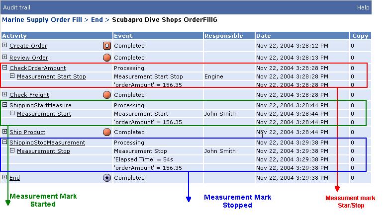
195 Activities The Audit Trail is: 195
196 Chapter 7. Groups Groups A Group is a compound activity. It is composed of a set of activities that may include other Groups. Sometimes the elements of the Group are called Sub-Activities/Sub-Groups or Inner-Activities/Inner-Groups. Groups provide exception and compensation handlers as well as time outs within the group. When should you use Groups? The following list provides some guidelines to help you decide when to use groups. Use groups when: You need to define a due interval within which a group of activities must be completed. You need to manage a specific exception that can occur in any activity within a group. (Instead of handling the exception in each activity, you can define the group and handle the exception from within it.) You need to reverse (compensate) a certain situation that involves more than one activity to be rolled back. You need to manage a group of activities as a unique transaction (Atomic transaction.) You need to clean up the design. Groups help you better visualize the process design since you can group a set of activities and collapse the group in order to see only one activity that represents a group of activities. A group / can be formed by any activity (also called leaf 196
197 Groups activity) with the exception of Global, Global Creation, Global Automatic, Begin and End activities. Also keep in mind that a group cannot contain only a split or a join activity. Characteristics The group is displayed as a dotted line rectangle that contains the activities/subgroups inside the group. Right-click on the rectangle to view the following options: Properties Collapse/Expand group Add due transition Add compensate transition Add exception transition Creating a Group There are several ways to create a Group: Drag the group icon from the toolbar to a role lane. Move all the activities or groups that compose this new group into the dashed box that represents it. Be aware that all transitions from or to the activities that are moved will be lost. Select all the activities/groups within the design that should be moved to the group. Right-click and select Create group with selection. In this case, transitions between the activities will remain and two new ones will be generated: a unique incoming transition to the group and a unique outgoing transition from the group. 197
198 Groups Select the Group icon / from the toolbar and drag it to select the area to be included in the new group. No matter which option you choose, the Activity dialog box appears. 1. Type a group Name. Whatever appears in this field will be displayed on the Designer workspace. This field accepts blank spaces and is not limited. 2. Click Localize to include the group name in German, Spanish or Portuguese. See Localization for further information. 3. Optionally, type a group Description. 198

199 Groups Note The Begin and End activities within a group are shown by default on the left and right side of the box. You can set them to be on the top and bottom by set the corresponding preference. From the View menu, select the Groups option. Select the desired Begin and End Orientation. 199
200 Groups You can Collapse or Expand the group by clicking the "+" or "-" symbols within the group. Properties General Category Atomic Groups A Group can be flagged as Atomic in order to be executed as a single transaction. An atomic group is defined as a group of automatic activities all executed in one transaction. For a group to become atomic, all its Sub-Groups must be flagged as atomic. An atomic group cannot include Interactive activities or external notifications. 200
201 Groups Activities inside an atomic group can belong to different roles. An atomic group can contain ONLY: Automatic activities. Split/Join activities. SplitN/Join activities. Notification/Wait activities (only synchronization between copies.) If any other activity (such as Interactive) is dropped into a group, you will be warned about it and the action will be automatically undone. An atomic group can contain other atomic groups. However, it cannot contain non-atomic groups. If a non-atomic group is dropped into an atomic group, you will be warned about it and the action will be undone. Collapse/Expand group Collapsed mode: The group can be represented within the graphical design as a simple icon, even though it contains several activities/groups. Expanded mode: The group is fully displayed with all the activities/groups it contains. When expanded, the group has a visual representation of its start and end point (like a Begin and End.) These icons are placed on the edge of the rectangle that represents the group. The unique incoming transition to the group reaches the begin point and the unique outgoing transitions of the group leaves from the end point. Double-click on the group to switch between both modes. 201
202 Groups Groups and Transitions Due Transitions A due transition can be specified for "leaf" activities as well as for "group" activities. A group can have a due transition that applies to the instance in any activity within the group. In such case, due time will begin running as soon as the instance arrives at the first activity within the group (entry point). To define which calendar rule to apply, the engine looks for the organizational unit where the process of the instance being executed has been deployed. If no calendar rule is defined for the organizational unit, the engine keeps looking in the upper levels of the organizational hierarchy until it finds a calendar rule to apply. If no calendar rule is found, it is assumed that all days are working days. If Enterprise is installed, the Process Execution Engine takes into account the calendar rule set for the organizational unit where the process is deployed and the activity role where the instance is running. The calendar rule set at role level is first evaluated by Process Execution Engine and overrides rules defined for the organizational unit, if any are defined. Refer to Calendar Rules for further information. Group due transitions override any single activity's (within the group) due transition. If a group has a due transition and it exists inside another group that has a due transition, the instance is ruled by the outermost group's due transition if both transitions expire at the same time. For example, between an activity due transition and the group that contains the activity, due transition, the instance will be routed according to the group due transition. See DUE TRANSITIONS for further information. Compensate Transitions Each leaf activity can have its own compensate flow. In addition, the group can also have its own compensate flow. The group's 202
203 Groups compensate transition can send the instance to a leaf activity or to a group activity that will perform any necessary action to compensate the situation. This group represents the compensate flow. Within the group's compensate flow, you might not reference a specific inner compensation (compensation defined in some inner activity). Therefore, the engine will call all the compensations defined in the group in the inverted order in which they are executed. If it has reference to an inner compensation, the engine will call only this compensation. In the following example, Group 1 is an inner group of Group2. Moreover, Group1 has activities act1, act3 and act5 within it. If act1 needs to be compensated, the CompensateAct1 activity will be executed. If act3 needs to be compensated, as there is no compensate transition going out of this activity, no compensation is performed. If no compensate transition is defined for a Group, then all inner activities compensations are performed. They are performed in reverse order of the process flow. In the example, if there were no compensate transition for Group2, inner compensations are executed: CompAct2 and then CompensateGroup1 in this order. 203
204 Groups A group can also be defined by grouping activities inside the compensate flow or exception flow. In this case, no exit point for the group will exist. See COMPENSATE TRANSITIONS for further information. Exception Transitions Groups can call and manage their own exception flow (in the same way as a Process does). See EXCEPTION TRANSITIONS for further information. Rollback Techniques If you want to rollback the actions in a group, you should call an exception (which can be a localized exception or the process-wide exception) and then use the compensation activity. 204
205 Groups Designer and the Standards Designer's standards match the concept of Scopes in BPEL. Groups and Grab activities See Groups and Grab activities. Groups Examples Groups Examples. Groups and Grab activities An instance can be grabbed from any activity, regardless of whether the activity is grouped or not. While grabbed, the instance will remain as grabbed in the grab activity. In other words, when: A Grab activity's task is executed over the instance, or The instance is ungrabbed, or The instance is sent to an activity different from the source activity, the source activity group's property will rule the operation (i.e., due transition expiration, exception handling, compensation handling). The source activity's due time is removed when the instance is grabbed. On the other hand, the process instance deadline is kept active. Moreover, the due time for groups nesting the source activity are also kept active (in the event that the activity is within a group that is actually within another group). When a grabbed instance is ungrabbed, from that moment on, the instance can be processed as usual in the source activity (activity from which it was grabbed). 205
206 Groups Once an instance has been grabbed, it can be sent to an activity different from the source activity BUT ONLY WITHIN THE SAME GROUP. Groups Examples Understanding the Behavior of Groups Case 1: Groups and Compensation In the following example, group 1 has a defined Compensation handling Flow as well as an Exception handling Flow. When will group1's compensation handling flow be executed? This will happen if activity D fails with an exception. As activity D fails with an exception, the instance is submitted to the Process Exception Handler Flow. The first action in this flow is to 206
207 Groups compensate all its inner groups' Compensation Handler flows. Therefore, group1's compensation handling flow (defined by its compensation transition) is executed beginning with the Compensate activity that will trigger all inner compensation, in this case the CompB activity. After that, the Manual Action activity will take place. Case 2: Groups and Exceptions In the example above, if an exception occurs within group1, it is handled by its Exception handler flow (guided by the Exception transition). For example, if an exception occurs in activity C, the first activity to execute is group1.compensate, which will trigger activity CompB as the compensation for activityb (inner activity). Next, it will return to the exception flow and execute exception handler action activity. At this point, the instance has reached the end of the exception flow and it is submitted to the next activity after the group. Therefore, activity D is executed. 207
208 Chapter 8. Transitions Transitions A transition is the bridge between two activities. Transitions use directional arrows that display the direction of the flow. An instance flows through a process by following the logic that applies to a transition. The types of transitions are as follows: Unconditional: unconditionally. Conditional Instances / flow through the transition : Instances flow through the transition if certain conditions are met. Due / / : Instances flow through the transition according to time conditions. Compensate / : Instances flow through the transition if compensation processing is required. The actions performed reverse (or undo) any work done in the previous activity in the event that it fails. Message Based / : Instances flow through the transition based on different messages that can be received. This type of transitions apply when calling subprocess, notifications, etc. Exception / : Instances flow through the transition if an exception occurs. Precedence: Only available in a Split-Join circuit. Copies within a Split-Join circuit can have a synchronization or a precedence. The precedence is represented by a dotted transition. 208
209 Transitions From any activity (except GlobalCreation, Global and Global Automatic, which have no transitions) you can design any of the previous transitions, as required. How are Transitions evaluated? When an activity has multiple outgoing transitions to determine what path is the right transition for the instance to follow, transitions are evaluated as follows: 1. Message Based transitions: if the activity received a message and the corresponding message based transition exists, this transition determines the instance path. If more than one message to the same message based transition is received, the first one that arrives triggers the instance execution. The rest of the messages are ignored. 2. Conditional transition: If there are no message based transitions applicable, the conditional transitions are checked. 3. Those messages that do not match #1 or #2 follow the Unconditional transition. Creating a transition To add a Transition you can either: 1. Right-click on the source activity. 2. Select the type of Transition that is required from the shortcut menu. 3. Draw the line to the target activity. The Transition Properties dialog box appears. Or 209
210 Transitions 1. Select the Transition icon from the toolbar and drag it to the source activity. 2. Draw the line to the target activity. 3. Select the type of Transition that is required. The Transition Properties dialog box appears. Note If the Transition Properties dialog box does not appear, right-click on the transition line and select Properties from the shortcut menu. To change your preferences, select File and then Preferences from the Process Designer menu options. The Preferences dialog box appears. Select the Transitions category and select the Show properties automatically when adding a new object check box. Next time you add a transition, the Transition Properties dialog box appears. Complete the Name and Description adding detailed information for the transition. For example, if it is a conditional transition, describe the condition. If it is a due transition, describe the due rule. If it is a message based transition, describe the type of message, etc. These two properties can be displayed as the transition label in the Designer Workspace. Moving a transition line To move a transition you can: Right-click on the transition. The From and To options move the transition line to alternate activities in the process. Change the receiving activity, the source activity or both. From: Select the new source activity from the shortcut menu. 210
211 Transitions To: Select the new receiving activity from the shortcut menu. Or Select the transition, drag any of the edges of the transition and drop it on the new source or target activity. Curving a transition The Curve option changes the trajectory of a transition line. This option makes it easier to fit activities and transitions on the screen. Curve: Select it and the default curve appears. Left-click on the transition line, hold the left button down and drag (stretch or shrink) the curve to the desired arc. Release the mouse button and the transition is curved. Removing a transition To remove a transition, right-click on the transition and select Cut from the shortcut menu. Setting the transition preferences Select the Preferences option from the File menu. Within the Transition category, you can choose to set preferences on how transitions are shown on the Designer workspace. Show properties automatically when adding a new object: If selected, each time you add a transition, the properties dialog will automatically display. 211
212 Transitions Visual properties: You can determine what label is shown near the transition on the Designer workspace: the transition Name, the Description, the Name and Description, or None. If you select Description or Name and Description to be shown, the icon appears next to the transition. Click on it to display the full description. Conditional Transition When your process requires restricted workflow between two activities, you should add a Conditional transition /. A Conditional transition indicates that workflow will only occur if specified conditions are met. You can describe the special conditions in the Description field. For example, in an Order Management process, a conditional transition directs instances from the Review Order activity to the Special Care activity if the order status is equal to "Expedite" or "Alert". After you create the transition, a line with a directional arrow connects the two activities on the design workspace. The / icon next to the transition indicates that it is a Conditional transition. As well, the transition's Name or Description may appear next to it depending on the chosen preference. Rules The rules for using conditional transitions are as follows: Conditional transitions are available for most activities, with the exception of End and Split-N. (Global, Global Creation and Global Automatic do not require transitions.) Activities cannot have an 212 unconditional and a conditional
213 Transitions transition to the same destination activity at the same time. Unconditional Transition When your process requires unrestricted workflow between two activities, you should add an Unconditional Transition. This type of transition indicates that no conditions exist to prevent instances from moving to the next activity. Therefore, the transition occurs unconditionally. After you create the transition, a line with a directional arrow connects the two activities on the design workspace. No icon is displayed next to the transition. Note If you do not want to see the Unconditional transitions, disable the Show Unconditional Transitions option. Transitions property from the View menu, Rules The following rules apply to unconditional transitions: Each activity must have at least one outgoing unconditional transition. Exceptions to this rule are the following: if the activity has a due transition. The Split and Split-N activities are the only ones that must have an unconditional transition, as an exception to this rule. Global Creation, Global, Global Automatic and End activities have no outgoing transitions. 213
214 Transitions Each activity must have only one transition. Exceptions to this rule are: outgoing unconditional Split activities can have more than one outgoing unconditional transition. Interactive activities may have more than one outgoing unconditional transition if the User selects transition check box is selected on the Interactive's Activity Property dialog box. Activities cannot have an unconditional transition to the same destination activity. and a conditional Due Transition A due transition / / is used when a process requires an instance to move to the next activity within a specified time period. Due transitions are used to implement deadline processing. Note Activities can use only one due transition to link to another activity. After you create the transition, a line with a directional arrow connects the two activities on the design workspace. The / icon next to the transition indicates that it is an Interval expression or Interval constant due transition. The icon next to the transition indicates that it is a Scheduled based due transition. 214
215 Transitions Note If you do not want to see the Due transitions disable the Show Due Transitions property from the View menu, Transitions option. Defining the Due Condition The Due Condition can be defined as Schedule based, Interval expression or Interval constant. In any of these cases, you can decide to use Calendar Rules. So, if the calculated due date is not a working day, the applicable due date is moved to a valid date. 215

216 Transitions Schedule based If the next scheduled due time falls on a non-working day, you have the ability to select whether the due time is passed to the Next working day, same time or Next scheduled based time. For example, if you set the due time to happen once a week, every Monday at 11:00 AM and one Monday is a holiday, then if you have 216
217 Transitions selected: Next working day, same time the due time is set to Tuesday at 11:00 AM, or Next scheduled based time the due time is set to next Monday at 11:00 AM. The Scheduled option indicates that the due transition is set to run on a specific date at a specific time. The DAILY choice allows you to select a time you want the due time to apply each day. For example, every day at 3:00 AM. 217
218 Transitions The WEEKLY choice allows you to select a "day of the week" and a time that the due time applies every week. For example, every Monday at '' 10:18 A.M..'' 218
 and the time to which the due time applies. For example, you can choose the third (3rd) Thursday of every month at 3:45 P.M.")
219 Transitions The MONTHLY choice allows you to select the month, the week of the month (First-Second/Fourth-Last)/the day of the week (Sun-Sat) or the day of the month and the day (1-31) and the time to which the due time applies. For example, you can choose the third (3rd) Thursday of every month at 3:45 P.M. 219

220 Transitions Note Notice that the due is moved based on the day and not on the time as explained on the dialog box Interval Expression The Interval Expression option allows the due time to begin the 220
221 Transitions moment the instance arrives at the activity plus an interval time. The interval time to add to the arriving time can be the result of an expression. For example, if you are approving orders and the customer belongs to the VIP category, then the order has to be approved in less than 30 minutes, in the contrary, the maximum is 3 hours. If the calendar rules apply and the calculated due time is on a non-working day, the due time is postponed to the first working time. Describe in (conditions). the Description field the interval expression Note Time will start running immediately after the instance reaches the source activity of the due transition. Interval Constant The Interval Constant option allows the due time to begin the moment the instance arrives at the activity plus a defined time (number of months/days/hours/minutes/seconds). If calendar rules apply and the calculated due time is on a non-working day, the due time is postponed to the first working time. For example, you decide that the due time is always the instance arrival time plus 7 days and 12 hours. No expressions are available. If so, define the due time as an Interval expression. Note Time will start running immediately after the instance reaches the source activity of the due transition. 221
222 Transitions Priorities for the Due times A due transition can be specified for leaf activities as well as for group activities. Therefore, an instance can be affected by multiple due times as follows: the activity due transition interval, each nesting group due transition interval, the process instance deadline. Thus, when an instance arrives at an activity, these three options are considered in order to determine the shortest due time and which due transition is first priority. You should consider that a group's due transition time begins when the instance arrives at the first activity within that group. The due time assigned to an instance, as it arrives at an activity, is the shortest time of all the three possible due time options listed above. For example, as shown in the image below, 222

223 Transitions the Automatic3 due transition is defined to 1 hour. the Group1 due transition is defined to 90 minutes. when the instance arrives at the activity Automatic3, as this activity has a due transition, the due time is the shortest time between: 1 hour: defined in the Automatic3 due transition. the remaining time of 90 minutes as defined for the Group1 due transition. This means that if the instance has remained for
224 Transitions minutes in the Automatic1 activity, the remaining time for the group is 40 minutes. In consequence, the instance will probably flow through the Group1 due transition to the Technical Control activity instead of flowing to the Control activity (1 hour). the remaining time of 2 hours defined as the process due deadline. If the instance has been in the Automatic2 activity for 100 minutes, the remaining time for the process is 20 minutes. Thus, the instance will probably flow to the End activity instead of flowing to the the Technical Control activity (90 minutes) or to the Control activity (1 hour). If more than one due transition expires at the exact same time, the instance is sent through the outermost due transition (of those transitions which time interval expired at that moment). For example, the instance is within an activity that has a due transition that expires at noon. Additionally, this activity belongs to a group that has also a due transition that expires at noon. At noon the instance will flow through the group due transition. When a due interval is calculated for an activity (leaf or group), the calendar rules are taken into account as regards the role where the instance is or whether the group spreads over many roles. Exception Transition An exception transition / is used to submit the instance to an Exception Handler flow when the activity or group of activities fail or throw an exception. Note Activities or groups can use only one exception transition to link to the exception flow. The exception flow can have as many activities as required to fix the exception condition. After you create the transition, a line with a directional arrow 224
225 Transitions connects the two activities on the design workspace. The / icon next to the transition indicates that it is an Exception transition. The source of the transition is the activity or group where the exception occured, and the target is the first activity in the exception handler flow. As the exception handler flow is independent from the main process flow, it cannot have transitions back to the main process flow. For further information, see Exception Handling. Compensate Transition A compensate transition / is used when an activity or group of activities require that the actions performed by the activity should be reversed. Reversal is needed in case of total or partial activity failure, which could be caused by any number of things such as a call to an external system that fails, equipment failure, a database call with bad data and so on. Note Activities or groups can use only one compensate transition to link to the compensate flow. The compensate flow can have as many activities as required. However, no other compensate transition between them applies. After you create the transition, a line with a directional arrow connects the two activities on the design workspace. The / icon next to the transition indicates that it is a Compensate transition. The source of the transition is the activity to be compensated and the target is the first activity in the compensation handler flow. Since the compensation handler flow is independent from the main process flow, it cannot have transitions back into the main process. For further information, see Compensate Handling and Compensate Activity. 225
226 Transitions Message Based Transition Message Based Transitions are available for the Begin and Notification Wait activity types. A Message Based Transition / is used when either of these activities can receive different type of messages and transition the instance through different paths. Begin and Notification Wait activities can receive different sets of arguments. The argument sets are defined in the implementation phase using Studio. In Designer, you can add a new outgoing transition defined as a Message based transition and later it is mapped to a set of arguments. Basically, you define the transition that the instance will flow through based on the received message. Complete in the Description field all the details about the received message so it is very clear what message is expected that will cause the instance to flow through this Message based transition 226
227 Chapter 9. Using Variables Using Variables Variables are placeholders in memory for values in your project. Each variable has a name, type and value. There are different types of variables: 1. Business Variables 2. Business Parameters Adding Variables Variables can be created from the Variable tab that is on the right of Designer's workspace, set by default. They can also be created on certain screens where Designer provides buttons to create them. To add a variable, first add a new line by clicking the + sign on the top-right of the variable's type section. A new line appears. For all the types of variables, you have to complete the Name and Type. 1. Type the variable's name in the Name field. 2. If you are declaring a simple type variable, select the type of variable from the Type drop-down menu. 227
228 Using Variables Removing Variables From the Variables frame, select a variable and click on the "-" (minus) sign on the right of the variables types section. Business Variables Note These variables are defined to contain information that can be used to define a measurement or dimension in the Data Warehouse. They represent business indicators considered by the business analyst. They can be retrieved in the WorkSpace. The business variable is used to save information across processes and use it to generate the Data Warehouse stored information. Business variables are available for any process within a Project. Adding and changing a business variable You can add an external variable from the Business section within the Variables tab. Click on the "+" sign: A dialog box populates: 228

229 Using Variables Define the type and size of the external variable. Optionally, click the Localize button to enter the name in alternate languages. This label represents the name that is displayed in WorkSpace. The label can be defined in the different languages when displayed in the WorkSpace. See Internationalization for further information on available languages. If the variable type is numeric, that is Int, Decimal or Real, you must define whether the variable is going to be used in the data warehouse as a dimension or measure. And you can define ranges of values for it. For example, if you are modeling a business variable that represents invoice amount, you can define ranges like shown above. If the variable type is not numeric then it can only be used as a dimension. Note The maximum characters for a business variable name is
230 Using Variables Business Parameters The business parameter is used to save information defined at the organization level. These parameters are visible for all processes. Business parameters are available for any process within a Project. Adding and parameter changing a business You can add a business parameter from the Variables tab. Click on the "+" sign: A dialog box populates: 230

231 Using Variables Define the type and the value of the parameter applicable for the whole organization. If the parameter has a different value for any of the organizational units, you have to define it in the table below. For example if taxes are the same percentage for all the organization sales but in Chicago there is a a different percentage, you have to specify it in the table. Business parameters applicable for Studio characteristics It is strongly recommended NOT to use Business Parameters for parameters that need to change in almost real-time nor for values that change very frequently (several times a day). For those cases consider using a database table and storing the parameters there. If you do need to change a Business Parameter you can change it at 231
232 Using Variables runtime using the component Business Parameter in the Lib category. See the component documentation within the Studio. Notes: If you change a Business parameter from a method you must be aware that the new value is not immediately available for all instances. Even more, if this value is changed from a BP-Method, the result may not always be the expected one and not available at the same time across the all participants. If the business parameter is used in a due transition expression of an activity, the business parameter value that applies is the one defined at the time the instance enters the activity. For example, the business parameter "MAXTIME" is used in the due transition expression of the activity "Reply to customer". When the instance "Request Customer 1" arrives, the due time is calculated using the value that the MAXTIME has at that moment. If another instance (in any process) changes the value or you manually change it in the Process Administrator, the new value does not apply for the due time of the instance "Request Customer 1" for the activity "Reply to customer". It will apply for all instances that arrive to that activity after the business parameter was changed. Warning if you change the Business Parameter at runtime, and you then stop and restart the Engine, all business parameters are restored from the project definition. 232
233 Chapter 10. Exception Handling Exception Handling An exception is a special event that can occur at any point during an instance's flow through a process. It can be a system exception or a business (user) exception. An exception is handled by a special flow called Exception Handler flow. An Exception Handler flow is a set of activities attached either to a Group or Activity. It responds to exceptions inside the Group or Activity. This flow is executed when the Group or Activity fails or throws an exception. Handling exceptions Exceptions can be handle adding an Exception Handler at process level (or a smaller scope, for example for a group). All kinds of exceptions can be handled in an Exception Handler defined by the user. Exception Handlers are associated to a specific Exception and they are defined in a scope of action. The scope of the handler can be: an activity a group of activities the whole process. Defining an Exception Handler Flow Exception handler flows are a set of activities designated for exception handling. These activities do not reside between the Begin 233
234 Exception Handling and End activities and are not connected to the main flow by transitions. When an exception occurs, the original instance is submitted to the corresponding Exception Handler flow based on the exception transition, if defined. If the activity has no Exception Handler flow, the exception is caught by the Parent's Group Exception handler flow. If the Parent's Group Exception handler flow is not defined, then the instance is treated by the Process Exception Flow, if defined. Characteristics Where can Exception Handler Flows be added?: An exception handler can be added to any activity (except to a Begin or an End ). The Begin and End activity will never fail. If the End activity has to send a notification, the BP-Method is retried forever (or until the engine is stopped) in case of failure. Handling more than one type of exception: The business designer could define one or more exception handlers for the same group as long as they handle different exceptions. Default Exception Handler Flow The Default Exception Handler flow applies to any group and refers to the Exception Handler flow that takes care of an exception under certain circumstances. If the Group does not have an explicit Exception Handler Flow, the Default is set to this Group dynamically. The Default Exception Handler 234
235 Exception Handling is not visible from the designer. It will catch all exceptions (catch all clause defined in BPEL4WS) inside the Group and invoke all compensations handlers inside the Group in the reverse order of completion. Rethrow the fault to the Parent Group. If the Parent Group is not contained by any other Group, the instance is treated by the Process Exception flow. What happens if the instance was created by a process into a Subprocess? 1. If the child process cannot handle the exception, then the exception is re-thrown to the Parent Process. The parent instance will not receive the regular notification for it to continue in the Parent process flow. Instead, it is sent to the corresponding Flow exception with the child's exception. The child instance flows to the End with an ABORTED state. 2. If the child process can handle the exception then it is very important to send the instance BACK o ABORT it so the parent instance is notified to continue its flow. If not, the parent instance will remain in the Subflow or Termination Wait activity. Propagation of Exceptions An exception handler defined for an activity could do something and then call the exception handler defined at process level for that exception. Any exception that occurs within an Exception Handler flow is managed by the Exception Handler flow of its Parent group. If there is 235
236 Exception Handling no explicit Parent Group, it will be managed by the Exception Handler flow of the Process Group or Process Exception Flow System Exceptions behavior (Non user defined exceptions) System exceptions have a particular behavior for some scenarios: In Interactive activities, if a system exception occurs, an error is displayed in the WorkSpace and the instance will remain in the Interactive activity. If the system exception occurs within an Automatic activity, the engine will retry until the maximum retries (configured in the Process Administrator) is reached. After that, the instance is sent to the corresponding Exception Flow. Quick Definitions The following are some quick definitions to be considered in order to understand the following: Groups Handling Exception Handling Compensate Handling Activity Represents the execution of some specific tasks. Flow Is a set of activities or Groups in some order, linked by transitions. Group 236
237 Exception Handling Is an Activity that contains a Flow where Inner Activities have common behaviors, like timeout, exception handler, etc. Inner Activities Are activities contained in the Group. Parent Group Is the Group which contains the Activity. Process Flow Is a Flow that represents the normal behavior of the business instance. If the Process Flow encounters an exceptional condition, it should back-out or compensate for what it is doing before aborting. Exception Handler Flow Is a Flow defined as part of the same Group or Activity and it is executed when the handle Group or Activity fails or throws an exception. Compensation Handler Flow Is a Flow defined as part of the same Group or Activity. The compensation is used to release resources and reverse already executed activities. Handled Group or Handled Activity Is the Group or Activity being handled by the Exception or Compensation Handler Flow. 237
238 Chapter 11. Compensation Handling Compensation Handling Compensation handling reverses the effect of a completed Activity (simple activity or a group of activities). A Compensation Handler flow is needed when an activity cannot be automatically reversed through the transaction's automatic rollback. A Compensation Handling flow is very similar to Exception Handling. An exception can trigger a compensation flow. To define a compensation handling flow, use the compensate transition. The source of the transition is the activity to be compensated and the target is the first activity in the compensation handling flow. As the compensation handling flow is independent from the main process flow, it cannot have transitions back into the main flow. Compensations are executed on completed activities, whether transactional or not. If the activity is not completed (for example, because an exception occurred before it finished), its compensation handler flow will not be triggered. Executing the compensation handler flow The compensation handler flow can be invoked from the exception handler flow or a compensation handler flow. Compensations can be invoked programmatically through a Compensate activity. 238
.")

239 Compensation Handling Compensation can apply to a single activity or to a group of activities. Within a group, if the compensate activity needs to rollback only one of its activities, then you have to select the activity to compensate (Figure 2). If it has to compensate either a single activity or a complete group of activities leave the Compensate dropdown without an activity selected (Figure 1). Figure 1--No reference to Compensate Activity Property. Figure 2--Specific Property. activity a in specific the activity Compensate in the Activity This last case applies to a Group compensation so you must connect the Compensate activity to the Group using a transition. Default Compensate Handler Flow The default compensation handler for a group is to invoke all the 239
240 Compensation Handling inner compensation handlers in the reverse order in which the original activities have been executed. Therefore, if you define a group but you do not define a compensation handler flow, then the Engine assigns the Default Compensation Handler Flow (invoke the compensation handler flow(s) of all completed activities inside the group in the reverse order in which they were executed). Example (Figure 3): If Group3 's compensation is invoked, it will run the compensation of Automatic 4, Group2 and Group1. Since the compensation for Group1 is not explicitly defined, when the Compensate activity in Group3 calls the compensation for Group1, the Engine will call the compensation for Interactive2, Automatic1 and Interactive1 in this order. Some tips The instance cannot be sent back by the Participant (through the WorkSpace) from the Compensation Handler Flow. A compensation can be added to any activity, except Begin and End activities. If the compensation flow for any activity is being called but this activity had failed, the call is ignored. When the instance reaches the end of the compensation flow, it will return to the activity that called the compensation flow. Process using Compensation 240
241 Compensation Handling When executing a compensation handler or an exception handler for a given group, you can only invoke compensation handlers of the first level of activities inside this group. Example (Figure 3): Compensate activity in Group3 exception flow calls compensation for activity Automatic4, Group2 and Group1. If the property select the activity to compensate does not have an specific activity, then it calls the compensate flow of all completed activities inside the group in the reverse order in which they were executed. Example (Figure 3): If activity Automatic4 fails, an exception is thrown. Therefore, Group3 exception flow (Automatic9-->Compensate) is invoked. In consequence, the Compensate activity will call the compensation of Group2 and Group1. In this example, the Automatic4 compensation flow is not called because compensation is called only in completed activities. 241
 The Compensate Activity triggers the compensation. The Compensate activity can be part of an Exception Handling Flow or a Compensation Handling Flow.")
242 Compensation Handling Figure 3 Process using Compensation. Compensate Activity Compensation is the act of reversing the effect of a completed Activity (a single activity or a group.) The Compensate Activity triggers the compensation. The Compensate activity can be part of an Exception Handling Flow or a Compensation Handling Flow. The Compensate activity is always part of a group's Exception Handling Flow or a Compensation Handling Flow. When the instance reaches this activity, the compensate activity will trigger all inner Compensation flows within that group. 242
.")
243 Compensation Handling 1. The Compensate activity is executed as any other activity within a flow, when the instance arrives to it. 2. The Compensate activity always triggers an inner compensation flow or compensation activities (those reached through a Compensate transition). In the example above, the compensate activity Process Exception.Compensate within the Exception Handling Flow for the Process, when reached, will trigger the corresponding Compensation Handling flow for all the activities and groups within the Process (only for those activities that have been successfully completed). For example, if an exception occurs in activity C, the compensation will execute: 243
244 Compensation Handling Compensate DB update Group1's compensation flow beginning with Group1 Compensate activity that will compensate all inner activities for Group1: Send cancellation mail (as "Send notice (mail)" compensation) and continuing with the Group1's compensation flow, activity Send mail to Controller Compensate activity characteristics Classic Icon UML Icon Business Analyst Icon BPMN Icon WorkSpace and the Compensate activity Compensate activities do not appear in WorkSpace because the Compensate activity does not require any end user intervention. They are automatically executed. Roles and Automatic activities Compensate activities can appear either in automatic roles or in user defined role types. However, since Compensation activities have no end-user interface, if it is placed in a user-defined role, it still will not be shown to the end user in WorkSpace. 244
245 Compensation Handling Preconditions The Compensate activity is activated by an incoming compensate transition. Post-conditions When the Compensate activity is executed, all Compensation flows for all inner activities are triggered. If the Compensate activity is part of an Exception flow or a Compensation flow, after its execution, the next activity in the flow is executed. Once the end of the flow has been reached, the instance will return to the activity that called the exception / compensation flow. Properties Activity ID See Creating an Activity. The label will automatically populate. Compensate The compensation of an activity means that the instance will be routed to its Compensate Handler Flow. Select the activity to compensate: If the Compensate activity is applying to a group (the compensate activity is part of an Exception flow or Compensation flow), you can select one of the inner activities within the group to which the compensate will revert. If an activity is selected, when the group's compensation is triggered, it will only revert all actions performed by that activity (if the activity was completed). No other activities within the group will be compensated. If it is not selected, all completed activities within the group are compensated in the reverse order in which they were executed 245
246 Compensation Handling during the process flow. For example, if you have three activities that are executed in the following order: 1. Activity 1 2. Activity2 3. at the end Activity3, the Compensation will revert Activity3 first, then Activity2 and finally Activity1 Transitions and Compensate activities One incoming compensate/exception transition is required and one or more outgoing transitions can be added in order to continue the compensation/exception flow to another activity. When do you have to use a Compensate Activity? In the event that you need to explicitly revert an activity or group of activities actions. If you define a group and, for some reason something fails, you can manage the compensation of the completed activities. See Compensate Handling for further information. 246

247 Chapter 12. BPEL Processes AquaLogic BPM & BPEL Processes AquaLogic BPM supports BPEL Processes. You can import a BPEL processes into Designer as well as to design a BPEL process directly in the product. Importing a BPEL process All processes have to be added to a project. Therefore create a project. Select from the File menu, the Import option. Select Designs. Browse to find the BPEL process to import. 247

248 BPEL Processes Once you finish the import procedure, the process is automatically created. A new process is created with the same name as the file that was imported. 248

249 BPEL Processes Creating a BPEL process First of all, create a project. Right click on the project tree node and select the New BPEL process option. You can also create a new process from the File -> New -> BPEL Process menu or from New -> New BPEL Process toolbar button. The workspace is set with a BPEL toolbar from where you can select the BPEL activities. Start designing the BPEL process. 249

250 BPEL Processes Partners Tab Define the Partner Link types defined in the used webservices and complete the roles. As well, define the partners and the partner links that they support. AquaLogic BPM BPEL processes AquaLogic BPM BPEL processes are in BPEL native format. As well, AquaLogic BPM Process Execution Engine is a native BPEL server. For a brief description of the BPEL activities refer to BPEL Activities. BPEL documentation Please refer to the BPEL4WS Specification at these locations: [ [ [ [ [ 250
251 BPEL Processes BPEL Activities AquaLogic BPM has a complete BPEL activities toolbar from which you can choose to build the process. Each activity has properties to be defined, mainly in the Advanced tab, according to the characteristics of each activity. For further information please refer to Defining an Activity. ASSIGN Classic Icon UML Icon Business Analyst Icon BPMN Icon UML Icon Business Analyst Icon BPMN Icon UML Icon Business Analyst Icon BPMN Icon INVOKE Classic Icon RECEIVE Classic Icon 251
252 BPEL Processes PICK Classic Icon UML Icon Business Analyst Icon BPMN Icon Advanced Tab Select the Create Instance check box if a new instance has to be created to flow through the process. 252
253 BPEL Processes TERMINATE Classic Icon UML Icon Business Analyst Icon BPMN Icon Business Analyst Icon BPMN Icon THROW EXCEPTION Classic Icon UML Icon FAULT HANDLER: Exception transition To add a Fault Handler, right click on the designer workspace and select Add exception transition to. Previously define one of the activities that are part of the exception flow. EVENT HANDLERS To add an Event Handler, right click on the designer workspace and select Add due transition to, or Add Message based transition. 253
254 BPEL Processes Previously define one of the activities that are part of the event handler flow. Due transition (On Alarm Event) This is one of the Event Handlers options Define the due event to handle. 254
 This is the other one of the Event Handlers")
255 BPEL Processes Message based transition (On Message Event) This is the other one of the Event Handlers options 255
256 BPEL Processes Define the flow that will wait for the event message. WAIT Classic Icon UML Icon Advanced Tab 256 Business Analyst Icon BPMN Icon

257 BPEL Processes Define the wait condition. You have to define the for condition or the until condition. FLOW Classic Icon UML Icon 257 Business Analyst Icon BPMN Icon
258 BPEL Processes SWITCH Classic Icon UML Icon Business Analyst Icon BPMN Icon To represent each case of the switch you have to define a conditional transition. The unconditional transition represents the otherwise. WHILE Classic Icon UML Icon Business Analyst Icon BPMN Icon UML Icon Business Analyst Icon BPMN Icon EMPTY Classic Icon SCOPE 258

259 BPEL Processes Classic Icon UML Icon Business Analyst Icon BPMN Icon Select a group of activities and define them within a Scope COMPENSATE Classic Icon UML Icon Advanced Tab 259 Business Analyst Icon BPMN Icon

260 BPEL Processes Define the activity to compensate. REPLY Classic Icon UML Icon 260 Business Analyst Icon BPMN Icon
261 BPEL Processes BPEL4WS documentation For a more comprehensive description of BPEL activities please refer to the BPEL4WS Specification at these locations: [ [ [ [ [ 261
262 Chapter 13. Simulation Simulation Once a project has been designed, you can simulate its execution. The project can simulate one or more of its processes at the same time. All the defined Resources will be shared in between processes. Simulation does not effectively execute the activity's tasks. It only simulates the process execution by waiting the length of time each task would have taken to execute. To execute a simulation you have to define models. You have: Project simulation models, and Processes simulation models A Project simulation model is composed by a group of processes simulation models. For each process you can define a Process simulation model. The project can have defined multiple simulation models. And each process can have multiple simulation models, as well. So you can build different project simulation models combining different processes simulation models. The project simulation model is defined in the project directory, in simulation directory as name of the model +.xpsi. And the processes simulation models have a name composed of name of the process + name of the model +.xsim. Each model has its own configuration and simulation definition. 262


263 Simulation Defining a Project Simulation Model To define the Simulation Model, click on the Run icon on AquaLogic BPM Studio/Designer's main toolbar. The Simulation panel is displayed at the bottom of your workspace and Flap number 8 is enabled. All defined project simulation models appear in the combo box. To create a new model, select Configuration. If you already have defined simulation models, you need to add a new one by clicking the button. If you have no previous models you can also create the first one by clicking on the Start button. A dialog box appears requesting the project simulation model's definition. Next, you have to define the model's properties. Project Information panel 263
 For example, during 1 day and 6 hours.")
264 Simulation Start time: indicates the supposed date that the simulation runs for logging purposes. It is not for scheduling purposes. Duration: indicates the period during which the simulation will run (Months, days, hours, minutes, seconds.) For example, during 1 day and 6 hours. Let Inflight instances finish before simulation ends: enables the simulation engine to allow the instances that were generated but didn't reach the End Activity before the simulation interval elapsed to finish. This property has to be enabled in order to obtain information from the Average Process Time indicator. Project Tab The list of all the project's processes are displayed. To make the process part of the project simulation model, you have to first define the process simulation model on the right panel and then select the Run simulation check box. If any of these processes act only as a subprocess, this means that instances are generated from a parent process only, then you mustn't check the box. if you do so, within the process, instances will come from the parent process (if it is part of the project simulation model) and as well instances are generated directly in the process. For all processes that are checked, instances are generated when the simulation is run. Project Resources Tab 264

265 Simulation You define the resources with which you will run the simulation. All the processes share these resources. Cost is per hour of each resource. You can copy the resources from the organization by clicking on the button. The simulation default values are taken from the Organization definition. Afterwards you can: Add new resources by clicking on the "+" sign. Delete a resource by clicking on the "-" sign. Modify any of the resources properties as Cost (per hour), Efficiency or Capacity (the displayed values are those loaded in the Organization Manager) Define the Availability that the resource will have in this process for this model. Modify, add, or delete roles for the resource. Priority Tab 265

266 Simulation The instances have a priority that determines the way in which they flow within the process. If your simulation model needs to deal with instances with different priorities, you can determine the probability for each priority. Priority: Highest, High, Normal, Low, Lowest Probability: the sum of all 5 priorities must be 100 Defining a Process Simulation Model A process simulation model is defined on the right panel. Select the Project Tab from the left panel. Select the process for which you want to create a model (be sure it is grayed and not necessarily its 266
267 Simulation check box is selected). All defined process simulation models appear in the combo box. If no model exists, you are able to enter a new simulation model name. If you already have defined process simulation models, you need to add a new one by clicking the button. Process Information panel Instance generation info: Within this tab, you can determine the way in which the instances are generated. Enable amount of instances limit: enable this check box if there is a limit for instance generation. If the check box is enabled, you define the maximum number of instances to generate. The Simulation will run until the duration is completed or the maximum number of instances is reached, whatever happens first. Distribution used for process instance creation: each instance is created depending on the defined distribution type. Constant: instances are regularly generated as defined in the period property. Uniform: is similar to the generation of Constant instances but with a delta variation. For example, if instances are generated every 30 seconds with a 10% delta, this means that they are generated every 27 to 33 seconds. Normal: responds to the Gauss Bell distribution. Exponential: indicates how many instances in an Average frequency are generated every period. 267
268 Simulation Exponential distribution considerations: the exponential distribution describes the distribution of time between events in a Poisson process. A Poisson process is characterized by the expected number of events in a time interval of given length. This distribution is commonly used to model random "arrivals", such as: The number of calls to a call center per day Number of times a web server is accessed per minute Number of cars arriving at a toll booth per hour Number of people arriving at a bank teller queue every ten minutes The mean and standard deviation of an exponential random variable are given by (time interval)/(expected number of events in that interval). Example of use in AquaLogic BPM Studio/Designer: Let us consider a customer support process in which a phone call by a customer triggers the creation of a process instance. We know, from experience, that our support technicians get about 50 calls per day. We would like to evaluate how different resource allocation scenarios would affect response times. Calls to a call center are a clear example of a Poisson process, so we decide to use an exponential distribution for generating instances in our simulation. Since we know that phone calls occur at a rate of 50 per day, we enter 50 in the instances field and "0 Months 1 Days 0:0:0" in the interval field. The distribution details now read: Average frequency: 50 instances, every: 0 Months 1 Days 0:0:0. Activities tab 268
269 Simulation For each designed activity you have to complete the properties to determine the simulation behavior. Activity panel: All the activities are displayed in this panel Depending on the activity, different properties can be defined. Duration: The instance remains in the activity depending on the selected distribution type. The same happens with instance generation in the process information configuration. Remember that the simulation 269
270 Simulation DOES NOT execute the tasks, so this should be an estimated execution time of the activity's task. Resources: This tab is only available for Interactive activities. Use Organization resources: the simulation model sets all the resources from the project simulation model definition. 270
271 Simulation Participant Selection Policy: the selection can be based on the Minimum Cost, Maximum efficiency or Randomly. Cost and Efficiency values are those defined in the project simulation model definition for each participant. Use fixed resources: Indicates the number of participants assigned to the Interactive activity. This option is used when costs and efficiency parameters are not relevant in the evaluation but only the amount of resources is needed. When selecting this option, the resources in the Project Resources tab are not taken into account. Cost: 271

272 Simulation The cost represents the value of a resource of this activity. Activity Cost type: it can be defined as a Fixed Based Cost or as a Fixed Based Cost + the Resource Cost. The resource cost is defined in the Project simulation model. Cost is used for reporting purposes. The Fixed Based Cost applies each time an instance is processed. The Resource Cost is calculated based on the define cost per hour and the time it takes the resource to execute the instance. 272

273 Simulation For example: You have defined an interactive activity "Ship the order". The cost to wrap the package is a fixed cost set to $2 (box, paper to wrap, etc). It takes the clerk 10 minutes to do this work and the cost per hour is $6. Therefore the calculated cost for each processed instance (order) would be: $2 (fixed based cost) + $1 (resource cost: 10 minutes of the resource defined as $6 per hour) Queue info 273

274 Simulation Queue warning size: when the queue size exceeds the defined one, while the simulation is executing, the queue becomes red. Activity Queue Policy: Instances are executed F.I.F.O, L.I.F.O, Randomly or by Instance Priority. Transitions: Due interval: if the activity has a due transition and its condition 274
275 Simulation is not constant, as it depends on a calculation or an instance variable, you need to define the due interval. Remember that during simulation no methods are processed. Transition/Probability: each designed transition populates in the combo box to define the probability that the instance will flow through it. In addition, by default, there two added transitions in the list: Exit because of an exception: defines the probability that an instance can produce an exception. Aborted instances: defines the probability that an instance can be aborted. Inner activities: 275

276 Simulation This tab is only available for Group activities. Inner activities: if checked, you have to configure the simulation for all inner activities. Open the group tree and for each displayed activity implement the simulation. If the check box is disabled, you configure the group as if it was a single activity. Warning 276
277 Simulation Grab, Global and End activities cannot be simulated. Related Process: This tab is only available for Subflow activities. Simulate related process: if checked, you have to define which Simulation model of the related process will run when you execute the Simulation. At runtime, the simulation is executed based on the configuration of the subprocess model as if it were 277
278 Simulation actually executing the subflow. If the check box is disabled, the Subflow activity will be treated as a simple activity and no subprocess is executed. You have to define all the information for the regular tabs (Duration, Cost, Queue info and Transitions). Note If you enable the "Related process" check box, be sure you have defined a simulation model for the related process. Modifying a Simulation Model Once you define a Simulation Model, you can change any property by clicking on. Executing a Simulation Model To begin executing a defined Simulation model, select the Project Simulation model and click on the Start button. Note Be sure that you have selected at least one process as Run Simulation in the Project Simulation model. The simulation is executed and on line behavior is shown on your workspace. 278

279 Simulation Note You can see the properties of the activity during the simulation by right-clicking on the activity and selecting properties. Flowing instances All generated instances are represented as a dot flowing through the process. Occupancy bar Each activity has one rectangle or Occupancy bar that represents the instances that are being processed (the rectangle on the right). 279

280 Simulation The occupancy bar is blank if no instance is processed at that time, or green with the number of instances that are executed. The maximum number of resources defined for that activity is on the top of the bar. If you defined to use Fixed Resources, you can dynamically change the number of resources by clicking on "+" or "-" signs next to the bar. If you defined to use the Organization Resources, you can modify the resources by clicking on the icon and a graphic populates. You can visualize for each resource the Percentage of time spent in the Activity and the Percentage of time spent in the Process. You can modify the number of resources for each type. Queue bar There can also be a second rectangle or Queue bar that represents the queue for that activity (the rectangle on the left). The queue bar is red when the Queue size warning is exceeded. When not exceeded, it is yellow. Above this bar you can see the maximum number of instances that the queue reached during the running of 280
281 Simulation this simulation model. Stop /Pause ( / ) The simulation execution stops or pauses. Once paused, click the Run button in order to continue. Run to the end ( ) When you select this button, the simulation runs in the background. No animation is shown. The simulation process is much faster. Speed scale You can slow down or accelerate the simulation execution by using the speed bar from Slowest to Fastest. In Normal speed, the instances are generated each second. All defined times within the model are scale- based on this. Changing parameters the simulation model Some of the simulation model's properties can be changed online while the simulation is running. You can dynamically change the number of resources by clicking on "+" or "-" signs next to the bar. Furthermore, you can edit the configuration and change any of the properties and see the new behavior online. Simulation results Results can be seen on the lower part of the Simulation Flap. 281


282 Simulation Click on any of the process and the graphic is shown for that particular process and not for all Selecting the representation graphic type Choose the graphic type in which you want to see the results from 282

283 Simulation the combo-box on the left top side of the Chart tab. The options are: The information is shown by process or by activity. To switch between both layers, click the up and down arrows beside the activity dimension,. The same can be done if you are watching the process level, left click on any result in the chart and the information is shown by activity. To return to the process view, click Ctrl + left click. The graphic can be zoomed in and out by clicking the icons in the chart tool bar. Setting to view the Simulation Results You can combine the following dimension for analysis to monitor your business process: Indicators are always present in the simulation analysis and they are represented in the Y axis of the chart. Combine two out of the three possibilities left, Activities, Resources, and Categories, to fill the "X" and "Z" axis of the chart. Icons to do this 283
284 Simulation are: : It will be represented in the X axis of the graph. : It will be represented in the Z axis of the graph. : The results will be shown for all the selected values. Click the following icons next to the available measurements to select the values occurrences to include in the simulation view results: Activities: When you click this icon, a window is displayed showing all the processes/activities. Resources: When you click this icon, a window is displayed showing all the 284
285 Simulation resources defined for this process. Categories: When you click this icon, a window is displayed showing all possible values that the instance priority can have. 285
286 Simulation Indicators: When you click this icon, a window is displayed showing all possible indicators you can choose to show in the simulation results. Available Indicators depend on the Resources dimension. Proceed in the same way for all them: - click the root check-box, to select/unselect all of them, - deselect those you want to exclude, or - select those you want to include. Indicators when the Resources dimension is not selected When you click the icon in the Simulation toolbar, a window is displayed showing the possible measurements you can choose to show in the simulation results. Indicators vary depending on the dimensions selected. This is the list of measurements shown if the Resources (participants) dimension has not been checked. Instance/Activity indicators: Units Average Instances Count: The average number of instances processed during the simulation. This is the sum of the Average Working Count and the Average Queue size. When the process view is shown, this amount is the sum of the individual average instances counts for each activity in the process. 286
287 Simulation When the individual activities of the process are shown, this is the number of instances passing through each individual activity. Current Instances Count: The number of instances being either waiting to be processed (queued) or are being processed right now. When the process view is shown, this amount is the sum of the individual current instance counts for each activity in the process. When the individual activities of the process are shown, this is the number of instances passing through each individual activity. Maximum Instances Count: The total maximum number of instances being processed. This is the sum of the Maximum Instances Working Count and the Maximum Queue Size. Average Queue Size: Average number of instances that waited at an activity. Maximum Queue Size: Maximum number of instances that waited at an activity. Current Queue Size: Number of instances that either are (1) waiting at the activity right now (while the simulation is running) or (2) were waiting at the activity when the simulation completed. When the process view is shown, this amount is the sum of the individual queue size counts for each activity in the process. When the individual activities of the process are shown, this is the number of instances waiting to be processed for each individual activity. Average Working Count: The average number of instances being processed. When the process view is shown, this amount is the sum of the average individual working counts for each activity in the process. When the individual activities of the process are shown, this is the average number of instances working for each individual activity. 287
288 Simulation Current Working Count: The total number of instances being processed. The amount shown is either the number: (1) being processed at the activity right now (while the simulation is running) or (2) were being processed at the activity when the simulation completed. When the process view is shown, this amount is the sum of the individual current working counts for each activity in the process. When the individual activities of the process are shown, this is the number of instances currently being worked for each individual activity. Maximum Instances Working Count: The maximum number of instances being processed. When the process view is shown, this amount is the sum of the individual maximum working counts for each activity in the process. When the individual activities of the process are shown, this is the maximum number of instances being worked for each individual activity. Average Performance: The average number of instances processed per hour. Completed Operations: Number of instances that have completed an activity during the simulation. When the process view is shown, this amount is the sum of the instances that have passed through (completed) each activity in the process. When the individual activities of the process are shown, this is the number of instances passing through each individual activity. Completed Instances: Number of instances that have completed an activity or the process during the simulation. The difference with the Completed Operations is when the process view is shown, this number is the total number of instances that completed the process. When the individual activities of the process are shown, this is the number of instances passing through each individual activity. Average Resource Utilization: The average number of resources assigned to each activity. 288
289 Simulation Time Average Process Time: Average time needed to run the entire process. This indicator should be used with the checkbox Let Inflight instances finish before simulation ends enabled in order to produce valid results. In this case the simulation engine allows the instances that were generated but didn't reach the End Activity before the simulation interval elapsed to finish. Average Cycle Time: Average time, or simulated 'wall-clock' time during which instances were at the activity. This is the sum of the average working time and the average waiting time. Maximum Cycle Time: Maximum amount of time, or simulated 'wall-clock' time, that instances were at the activity. This includes the maximum working time and the maximum waiting time. Minimum Cycle Time: Minimum amount of time, or simulated 'wall-clock' time, that instances were at the activity. Includes work and wait time. Average Waiting Time: Average time instances spent waiting at the activity. Maximum Waiting Time: Max amount of time instances spent waiting at the activity. Minimum Waiting Time: Min amount of time instances spent waiting at the activity. Average Working Time: Average amount of time that work was actively being performed on each instance going through the activity. Maximum Working Time: Maximum amount of time that work was actively being performed on any instance at the activity. Minimum Working Time: Minimum amount of time that work was 289
290 Simulation actively being performed on any instance at the activity. Cost Total Cost: Total cost of executing the process for all the instances run through it. When the process view is shown, this amount is the sum of the individual activity cost totals. When the individual activities of the process are shown, this is the total cost for each individual activity. Average Total cost: Average cost of executing an instance through the process. When the process view is shown, this amount is the average of all the individual activity cost averages. When the individual activities of the process are shown, this is the average cost for each individual activity. Indicators selected when there are Resources If you have selected the Resources dimension for an axis and at least one participant is checked, the indicators will instead be resource related. Shown below is the list of measures called Resource Indicators: 290
291 Simulation Units Maximum Resource Utilization: Maximum number of resources assigned Current Resource Utilization: Number of instances currently being worked on by the participants checked in the Resources. Average Resource Utilization: Average number of resources working on an instance at any time Total Resource Utilization: The total number of instances executed by all the participants during the entire execution of this simulation. Total Waiting Count: number of instances that had to wait for a resource before they were worked on. Time 291
292 Simulation Resource Busy Time: amount of time the resource is busy processing the instance. Resource Waiting Time: amount of time the resource is waiting to process the instance. Cost Resource Busy Cost: Resource cost incurred while actually working on instances Resource Total Cost: Cost of Resources whether they are busy or idle. Viewing Chart results You can zoom in or zoom out any type of chart by clicking Ctrl + left mouse button + moving the mouse horizontally Additionally, in any 3D chart you can rotate the graphic by clicking Shift+ left mouse button + moving the mouse horizontally Comparing two simulation models Two flaps are available to compare the results of two simulation models running. The first time you run the simulation from the designer toolbar, Flap 8 is created to run a first model. If you run another simulation from the designer toolbar, a new flap is created, number 10. Use the two flaps to compare results by switching between the flaps. This allows you to perform what-if analysis. 292
293 Simulation Log Tab Shows the log of all actions performed during the simulation, step by step. Reporting Settings To generate result simulation reports click the icon. The Reporting dialog opens where you can configure the information to be included in the report. Browse and select the file location and name for the report you are about to generate in the first area of the dialog. In the Options area of the dialog, you are able to configure some of settings to generate the report. Five tabs are provided to do this, one for each possible dimension to select the graphic type to include in the report: Activities, Resources, Categories, Indicators, and Chart. The simulation result settings are used as default values for the report generation. The dimensions selected as fixed for the X and Z axis cannot be changed at report generation time. They are displayed, but you do not have edit access to them. Resources Tab: In this example, Resources dimension has been set as X axis. 293
294 Simulation Activities Tab: In this example, Activities dimension has been set as Z axis. 294

295 Simulation Categories Tab: 295

296 Simulation Indicators Tab: 296

297 Simulation Chart Tab: Select the type of graphic to include in the report. An example is shown in the area below the options. 297

298 Simulation Dimensions that are editable or enabled can be chosen as Summary or Details. However, only one of them can be included as Details in a report. If you select Summary, click the possible values for the dimension you want to summarize. Generated Report Simulation report generated shows for each process: Simulation Data: When you click the link, you will see details of the simulation data regarding instances used to create the report. 298
299 Simulation Simulation Resource Data: When you click the link, you will see details of the simulation data regarding resources used to create the report. Simulation Chart: one or more, depending if the Details dimension was selected. The Simulation Data and Simulation Resource Data are generated in files with extension.csv (comma separated values) so you can import them into tools to see this information in different graphics or pies. As the directory "c:\\fuegoproject" was selected, you will find there files as: ModelName_ProcessName.csv (with Activities,Categories,Indicators,Values) these columns: ModelName_ProcessName_Resources.csv (with these columns: Activities,Categories,Resources,Indicators,Values) For example: Simulation01_CarInsuranceFulfilment.csv Simulation01_CarInsuranceFulfilment_Resources.csv Simulation01_Subprocess.csv Simulation01_Subprocess_Resources.csv Simulation01_ServiceRequestFulfillment.csv Simulation01_ServiceRequestFulfillment_Resources.csv Simulation01_CarInsuranceFulfilment.csv content will look like: 299
300 Simulation Activities,Categories,Indicators,Values, Automatic,Highest,Average Instances Count,2.36, Automatic,Highest,Current Instances Count,7, Automatic,Highest,Maximum Instances Count,7, Automatic,Highest,Average Queue Size,2.26, Automatic,Highest,Maximum Queue Size,7, Automatic,Highest,Current Queue Size,7, Automatic,Highest,Average Working Count,0.11, Automatic,Highest,Current Working Count,0, Automatic,Highest,Maximum Instances Working Count,1, Automatic,Highest,Average Performance,12, Automatic,Highest,Completed Operations,1, Automatic,Highest,Completed Instances,1, Automatic,Highest,Average Resource Utilization,0, Automatic,Highest,Average cycle time,58,seconds Automatic,Highest,Maximum cycle time,30,seconds Automatic,Highest,Minimum cycle time,30,seconds Automatic,Highest,Average waiting time,28,seconds Automatic,Highest,Maximum waiting time,28,seconds Automatic,Highest,Minimum waiting time,28,seconds Automatic,Highest,Average working time,30,seconds Automatic,Highest,Maximum working time,30,seconds 300
301 Simulation Automatic,Highest,Minimum working time,30,seconds Automatic,Highest,Total Cost,0, Automatic,Highest,Average Total Cost,0, Simulation01_CarInsuranceFulfilment_Resources.csv content would look like: Activities,Categories,Resources,Indicators,Values Fill in form request,highest,customer Reps,Maximum Resource Utilization,0.0 Fill in form Utilization,0.0 request,highest,customer Reps,Current Resource Fill in form request,highest,customer Utilization,28.0 Reps,Average Resource Fill in form Utilization,6.0 request,highest,customer Reps,Total Resource Fill in form request,highest,customer Reps,Total Waiting Time,5.0 Fill in form request,highest,customer time,162,seconds Fill in form request,highest,customer time,384,seconds Reps,Resources Reps,Resources busy waiting Fill in form request,highest,customer Reps,Resource Busy Cost,0.36 Fill in form request,highest,customer Reps,Resource Total Cost,0.25 Simulation Example Find this example in the SimulationCase01.fpr project AquaLogic BPM Studio's installation directory, in studio/samples. 301 in
302 Chapter 14. Version Control System Version Control System The Version Control System, VCS, implements a client to perform version control operations like add, remove, commit, and update into a common repository. It is designed to operate with different VCS providers such as CVS, Source Safe, and others. Providers are available by installing the corresponding plug-in. This feature is very useful for the administration of Designer projects. This includes processes, components, and special files. By using VCS, you can record the history of your project. For example, bugs sometimes creep in when software is modified and you might not detect the bug until some time after you made the modification. Using VCS, you can easily retrieve old versions to see exactly which change caused the bug. Sometimes this can be a great help. VCS also helps you if you are a member of a group working on the same project. But take into consideration that VCS is not: a build system a substitute for management a substitute for developer communication Also, VCS does not have a built-in process model to ensure that changes or releases go through various steps, with various approvals as needed. VCS Properties How to configure VCS in Designer VCS can be configured in the Designer Preferences, Preferences 302

303 Version Control System option in the File menu. The provider to be used is defined in this option. Go to the Default Version Control category on the right side of the dialog and set the corresponding values to your VCS. The configuration you define in this option is the default VCS configuration for your Designer, but each project VCS's configuration can vary. If the project configuration has not been defined when you define it, you can use the default definition or set a different one. How to configure VCS for a Project To define a different VCS configuration from the default one for a Project, go to the main File menu and select the Project Preferences option. Select the Project Version Control category and set the corresponding values for this particular project. 303

304 Version Control System Using CVS as Repository General Description of CVS CVS is one of the version control systems you can use as a repository. The CVS repository stores a complete copy of all the files and directories that are under version control. Normally, you never have direct access to any of the files in the repository. Instead, you use CVS commands to get your own copy of the files into a working directory and then work on that copy. When you have finished a set of changes, you check (or commit) the files back into the repository. The repository now contains the changes you have made. It also records exactly what you have changed, when you have changed it and other similar information. Note that the repository is not a subdirectory of the working directory, or vice versa; they should be in separate locations. 304

305 Version Control System Using Designer VCS, you will interact with the CVS repository using Designer capabilities. Implementing the repository with CVS This section explains how to configure and use the CVS implementation. After selecting CVS as the VCS provider, you must configure the CVS properties: Special Note If you are configuring cvs ext with SSH RSA based authentication and it requires an user intervention to input a password, it will depend on the operative system how it is asked to be input. In Linux, it depends on how the SSH_ASKPASS environment variable is set. If you run Designer on a terminal and the SSH is configured to ask for a password (for example not using an ssh agent), you might think that Designer is not responding, but in fact it is waiting for an user to input the password. 305
306 Version Control System About the Manager for CVS: Connection Type PServer: Available. Ext: Available. Login Settings Server: Name of the server where the CVS Repository is running. User Name: Name of the user in repository. User Password: Password for the user in the repository. Repository Settings Path: Indicate the root path of the repository. The processes directories are located in this path. All the above information will form the CVSROOT variable. Once you have configured the CVS connection settings, test the connection by clicking the Test button to ensure that the configuration is correct. Supported Operations Store Project to the Repository The first step to begin using the VCS functionality is to add the project to the repository. Do this: 306

307 Version Control System From the menu opened by right-clicking on the Project entry in the project navigator, VCS option and then Store Project to Repository, or from the main File menu, Store Project to Repository option 307

308 Version Control System The Store Project to Repository dialog is opened, showing the Project path where your project will be updated. This path is ''projects', but you can change it if you want. 308


309 Version Control System A dialog showing the updating actions is opened. Once the updating has finished, click OK to continue. Storing the project to the repository adds and commits the whole 309
310 Version Control System project, processes, and components. After performing the Store project to repository, you do not need to perform an add and commit. However, you will need to add and commit any new element added to the project after the initial store. Storing a Project in CVS The next step after configuring the CVS properties is to Store the project to repository available in the context menu of the project tree or in the main File and VCS menu option. This operation imports the whole project into the CVS repository. Let's see a general example of how the project is stored into a CVS repository: Project name: Test.fpr CVSROOT directory: /usr/mycvsrepository If the project path name is left blank, the project directory will be created directly under CVSROOT directory: /usr/mycvsrepository/test.fpr. If the field is filled in with a directory hierarchy like myprojects/develop, the project will be imported in /usr/mycvsrepository/myprojects/develop/test.fpr. In both cases, a new module is created in the CVS repository in the CVSROOT/modules files: Test.fpr Test.fpr or Test.fpr /usr/mycvsrepository/myprojects/develop/test.fpr Note For further information, see How modules are created in CVS. After the project is imported to the repository, a check out operation is done on this project so now your local project is administrated. 310
311 Version Control System Select Update Local from the VCS menu. Add Adds a component or a module to the repository. To confirm the addition, the commit command must be executed. If the added file is a process folder or a user module, all internal files will be added recursively. To add an element to the repository, select the Add option from the VCS menu by right-clicking on the element. Available for: Project. Processes. Folders that represent a directory. Directories can be added to the repository but the commit operation is required. One individual process. Update Updates the local copy of a file with the last version in the repository. After you have run checkout to create your private copy of the project from the common repository, other developers may change the central source. From time to time, when it is convenient in your development process, you can use the update command from within your working directory to reconcile your work with any revisions applied to the repository since your last checkout or update. To update the project or any of its elements from the repository, select the Update option from the VCS menu by right-clicking on the element you have chosen. 311

312 Version Control System The VCS Processor dialog is opened listing the files included in the selection to be updated. The information shown for each file is its type and status. Click the Update button to complete the operation. The result of the update is shown in the Update Output section of the dialog. Click Close to quit. Update keeps you informed of progress by printing a line for each file, preceded by one character indicating the status of the file: U file: The file was brought up to date with respect to the repository. This is done for any file that exists in the repository but not in your source and for files that you have not changed but are not the most recent versions available in the repository. P file: Like U, but the CVS server sends a patch instead of an 312
313 Version Control System entire file. This accomplishes the same as as U but using less bandwidth. The file has been added to your private copy of the sources and will be added to the source repository when you run commit on the file. This is a reminder for you that the file needs to be committed. A file: The file has been added to your private copy of the sources and will be added to the source repository when you run commit on the file. This is a reminder for you that the file needs to be committed. R file: The file has been removed from your private copy of the sources and will be removed from the source repository when you run commit on the file. This is a reminder for you that the file needs to be committed. M file: The file is modified in your working directory. M can indicate one of two status for a file you are working on: either there were no modifications to the same file in the repository, so your file remains as you last saw it, or there were modifications in the repository as well as in your copy, but they were merged successfully, without conflict, in your working directory. CVS will print some messages if it merges your work and a backup copy of your working file (as it looked before you ran update) will be made. The exact name of that file is printed while update is running.? file: file is in your working directory but does not correspond to anything in the source repository and is not in the list of files for CVS to ignore. Available for: Project Processes 313
314 Version Control System Folders One individual process Commit Use commit to actually check the file into the repository. The added files are not placed in the source repository until you use commit to make the change permanent. To commit an element to the repository, select the Commit option from the VCS menu by right-clicking on the element. The commit dialog is opened. Three sections form this dialog. In the File section, all the elements about to commit are listed. For each one the file name, type and status is shown. Some of the file types are: Process Screenflow Procedure Configurations Server configurations Organization settings Views Component In the User Comments section, users can write the comments referring to the commit they are doing. And the Commit Output sections shows the result of processing the commit. 314

315 Version Control System Those files that have been added will show the Locally added status. For further information about the status, please refer to the status operation. Click the Commit button to proceed. The advance percentage is displayed while the commit is being processed. The result of the operation is shown in the Commit Output portion of the dialog. Click Close to end the dialog when the process has finished. To confirm that the commit was successful, run the status operation 315

316 Version Control System on the elements committed. They must show the Up to date status. Available for: Project Processes Folders One individual process Status Based on the operations you have performed on a checked out file and the operations that others have performed to that file in the repository, a file can be classified into a number of status. To see the status of your project elements in the repository, select the Status option from the VCS menu by right-clicking on the element label. 316

317 Version Control System The possible status reported by the status command for a file are: Up to date: The file is identical to the latest version in the repository. Needs Patch: There is a new version of the object in the repository and the local copy is older but not modified. Needs Merge: There is a new version of the object in the repository and the local copy needs to be updated. Needs check out: The file is out of sync with the repository and needs to be updated. Locally Modified: The local version has been modified but your changes have not been committed yet to synchronize with the repository. Locally added: The file has been added to the repository but not committed yet. Locally removed: The file has been removed from the repository but not committed yet. Had Conflicts on Merge: When the local object is locally modified and there is a newer version in the repository, by doing 317
318 Version Control System an update the local object can remain merge-errors. Unknown: CVS does not know anything about this file. The file has not been administrated yet. No in Repository: Although it seems to have previously been in the repository, now the object is not longer present. This happens when the object has been externally removed from the CVS. Void: The element is a directory, a folder in the Project tree. Error: An error has occurred when processing the project element. Available for: Project Processes Folders One individual process Log To view/visualize the log of operations that have been done on an element or group of elements, select the Log option from the VCS menu by right-clicking on the element. The dialog is opened showing the list of elements contained within the level where you have run the operation (Project, Process, Module, etc.). Click the Log button to see each element's log. 318

319 Version Control System Each element log is separated by a complete line of = characters. Available for: Project Processes Folders One individual process Solve Conflicts When you are making an update of a project element, some conflicts 319
320 Version Control System may appear. This probably happens because you have made some changes in your working directory that are not compatible with other changes made and committed by another developer. To see the conflicts between your local project and the one in the repository, select the Solve Conflicts option in the VCS menu by right-clicking on the project name in the navigator. The list of files or project elements with conflicts appears in the dialog box. The file name, type, working version, repository version and status are shown for each one. The status in this case will be Had conflicts. The last column of the dialog is Choose. Clicking on the column value, a popup with the possible actions to take is displayed. 320

321 Version Control System A merge is not provided, so you will be able to choose only among: Ignore, you can choose to ignore the conflict by now Working, you will keep the version in your working copy Repository, you will keep the version in the repository 321


322 Version Control System If the developer is an experienced user, he can edit the XML file manually and fix the conflicts. If you are trying to Solve conflicts, but there are no conflicts at all, the following notice dialog is displayed. Available for: Project Processes 322
 with a label for later retrieval.")
323 Version Control System Folders One individual process Tag This operation is only available at the project level and it will create a tag (label name) marking all the components and processes of the project checked in the repository (last version) with a label for later retrieval. To create a tag for the project, select the Tag option from the VCS menu by right-clicking on the Project entry of the navigator. The Tag dialog is opened. Give the name to the tag you are about to create, typing it in the Tag Identificator field and clicking OK to continue. The result of the tag operation is displayed in the next dialog, showing the result of the process in the Tag Output section. 323
324 Version Control System Click OK to close the dialog and end the tag process. From the moment a tag is created for the project, you can retrieve it by indicating the tag name. Available for: Project Modules This operation shows you all the existing modules in the same repository as the project. 324

325 Version Control System Available for: Project Import a Project from the Repository If you need to create a new project by checking out a project that is already administered by the VCS, select From VCS Repository option on the File and then Import menus. 325

326 Version Control System A wizard opens, In the first dialog, select the provider of VCS to use and configure the necessary properties to connect to the repository. The default VCS configuration set is shown. 326

327 Version Control System Next, a list with all the administered projects is displayed. This list is taken from the CVS modules list. Select the project you want to import. If the project has tags, select the tag you want to import. 327

328 Version Control System Select a destination folder where the project will be checked out and click Next to proceed. 328


329 Version Control System If a project with the same name already exists in the folder you have selected, a warning is displayed. You can either change the location or continue. 329

330 Version Control System The next dialog shows the check out and project creation. Click Next when finished. The Finished! final dialog step is displayed. Click Finish to end the Wizard. 330
 to the corresponding project root directory.")
331 Version Control System Note If the project is already checked in but was not done by the Designer tool, you must create a CVS module manually with the name of the project and the relative directory (from CVSROOT) to the corresponding project root directory. General operations There are three special buttons in the Designer toolbar to perform massive operations, also present in the main menu File->VCS. Project status: Clicking the down arrow beside this icon displays a menu with status option for project. 331
332 Version Control System Update local project from repository: Clicking the down arrow beside this icon displays a menu with update option for the project. Commit local project to repository: Clicking the down arrow beside this icon displays a menu with option to commit the project. See also Using CVS as the Library Repository 332
333 Chapter 15. Defining Organizational Resources Organization Every project created with Designer has its own defined organization structure. The Organization window works as an organization administrator. It allows you to logically define and maintain your organization's structure, either for testing and simulation purposes or to define the real structure of your organization for a production environment. The following types or categories of objects are managed by the Organization window: Category Description Organizational units Represent departments or divisions within the organization. You can assign participants and assign calendar rules to an organizational unit. You can also deploy processes under an organizational unit. Organizational Roles Represent job functions performed within the organization. Roles are assigned to participants or groups and this association defines the permissions the participants have when executing tasks of AquaLogic BPM processes through WorkSpace. Organizational Groups Represent a profile. Groups have members associated to them and can be assigned roles and other groups. Participants The organization members that participate in any task within a business process. 333
334 Defining Organizational Resources Category Description Holiday Rules Define the organization s non-working days. These rules inform the Process Execution Engine that there is an exception to the normal calendar rules on certain days of the year. Calendar Rules Define the organization s work week and work schedule. Calendar rules can be assigned to organizational units. The Organization window The Organization window work space is divided into two navigation panels. The left navigation panel shows all the different categories of objects you can create in the organization. The right navigation panel lists all the objects of each category that are already created and allows you to create new objects as well as to delete existing ones. Once you have opened your project in Designer, click on the File menu and then select the Organization menu item. This option is only enabled when a project is currently open. You can also launch the Organization window from Designer toolbar clicking on the Organization icon : the Organization window displays all its working components. 334

335 Defining Organizational Resources Left Panel Right Panel Displays all the different categories When you click on a category in the of objects you can have in the left panel, the list of objects for that organization category appears in the right panel. The information is displayed as different views showing a tree or a list of items in a table, depending on the category you click. The New button is always enabled to create new objects for the selected category. After you select one of the objects on the list, two buttons--properties and Delete--are enabled for you to modify or delete the selected object. 335
336 Defining Organizational Resources At the bottom of the window, the Export button allows you to export the organization structure data to a file. The Import data button allows you to import the organization structure information from a file generated in another project or in previous Designer versions. Note In this online help system, organizational data is referred to as objects or entries. Organization objects views The Organization window provides different views that allow you to define and update the attributes or properties for each type of object stored in the directory server. The following views are provided: Organizational Units The Organizational Units view is the default view that is displayed when you open the Organization window. The Organizational Units view allows you to define, update, and delete organizational unit information. In this view, the information is shown in a tree to represent the hierarchical relationships between organizational units. After selecting one of the nodes in the tree, you can click on the Properties button to edit the organizational unit information. 336
337 Defining Organizational Resources Organizational Roles The Roles view displays a listing of roles defined in the organization. The Properties button displays a new window with the role data. 337
338 Defining Organizational Resources Organizational Groups The Groups view displays all the groups defined in the company. 338
339 Defining Organizational Resources Participants Participants view displays all users defined in the organization and stored in the directory service. When you click on the Properties button, a new window opens displaying all the participant properties. 339
340 Defining Organizational Resources Holiday Rules The Holiday Rules view displays all the Organization's defined holiday rules. 340
341 Defining Organizational Resources Calendar Rules The Calendar Rules view displays all company calendar rules. 341
342 Defining Organizational Resources Organizational Units Organizational units are, typically, departments or divisions within an organization. Organizational units can be organized in a hierarchy, for example: 342
343 Defining Organizational Resources In this hierarchy, Dallas contains the Customer Support, Sales, and Documentation organizational units. Customer Support contains Product Support and Technical Support organizational units. Once the organizational units have been defined, the employees of the company defined as Designer participants might be assigned to one of the organizational units in the hierarchy. Processes can be deployed for one of the organizational units defined here so that only participants in that organizational unit and in lower levels within the hierarchy are able to perform tasks in a process. Every Organizational Unit might have a different calendar rule associated to it. This allows the Process Execution Engine to take into account time zones and working schedules set for the Organizational Unit where processes are deployed and to calculate deadlines accordingly. The Organizational Units view in the Organization window allows you to define the organizational hierarchy and the organizational units' properties. 343

344 Defining Organizational Resources Creating Organizational Units To add an organizational unit 1. Open the Organization window. Next, select Organizational Units category in the left panel, and the organization tree appears. If no organizational unit has been defined, you will only see the root Organization. The organization name displayed as the root node in the tree is the one you enter when creating the project. Click the New button: A blank organizational unit profile is displayed in a new window. 2. Type the Organizational Unit Name and a Description. 3. You can assign calendar rules at any organizational level (organization or organizational unit). The Engine uses the calendar rule defined for an organizational unit in order to calculate due dates for instances of processes deployed in this organizational unit. For further detailed information on how AquaLogic BPM uses calendar rules to calculate deadlines, see Calendar Rules. To assign a calendar rule to the organizational unit, select the rule from the drop-down box. 344
345 Defining Organizational Resources 4. Click Save. Note that if you do not have any organizational unit selected when you click New, the new organizational unit is created under the root organization node in the tree. If you need to create a hierarchical organizational unit, be sure that the organizational unit you want to be the parent of is selected in the organization tree when you click New. Note The calendar rule set to an Organizational Unit does not affect the time zone used to display information to participants belonging to that organizational unit. The time zone taken into account to display dates in WorkSpace is the one set in the WorkSpace options window. Options, including time zones, can be unique for each user. Editing Organizational Units To edit an organizational unit 1. Open the Organization window. Next, select Organizational Units in the left panel. 345
346 Defining Organizational Resources 2. Select the Organizational Unit you want to edit from the Organization tree displayed in the right panel. 3. Click Properties. 4. Make all the changes required in the General tab. 5. Click Save to save the changes. 6. If you need to check how other objects in the organization use the organizational unit being edited, click the References tab. The references information is displayed. 346

347 Defining Organizational Resources Deleting Organizational Units To delete an organizational unit 1. Open the Organization window. Next, select Organizational Units in the left panel. 347
348 Defining Organizational Resources 2. Select the Organizational Unit you want to delete from the Organization tree displayed in the right panel. 3. Click Delete. Note Important Note : When deleting an organizational unit to which participants belong, the participants are automatically moved to the first level in the organization. Deleting Organizational Units when processes are deployed to it AquaLogic BPM allows you to make a process public for a specific Organizational Unit so that only participants belonging to that organizational unit can work on that process. 348
349 Defining Organizational Resources Organizational Roles A role in the organization is a title that describes the activities performed by employees of the company. Employees are defined as Designer' participants. Examples of roles include Accounts Manager, Sales Clerk, or Customer. A role in a process defines a job function for work including activities that do not require human intervention. Roles defined in the process are stored independently of the role information defined in the organization. This separation allows designers to develop processes as templates making them reusable in different organizations. However, in order to ease process deployment, AquaLogic BPM ensures that an organizational role always exists for each user-defined role of the process and handles the mapping between them automatically using the role names. When using AquaLogic BPM Enterprise runtime edition, the mapping between process roles and real organization roles must be made manually when publishing the process. Organizational role information can be viewed by selecting the Roles category in the Organization window's left panel. The Roles view in the Organization window allows you to create, modify, and delete roles in the organization. 349

350 Defining Organizational Resources Creating Roles There are two ways to create a new role. Using the organization window, you can create a role to be used in the entire project. The second way is to create a role while designing a process. The former creates an organizational role. From that moment on, that role can be referred to by any process role in the project. The latter not only creates the organizational role to make it available for the rest of the processes, but it also maps that organizational role to the process role that is being designed. To create a role from the Organization window 1. Open the Organization window. 2. Select the Roles category in the left panel, the roles view 350

351 Defining Organizational Resources appears in the right panel. All roles defined also appear. 3. Click the New button. A blank Role profile is displayed in a new window: 4. Type the Role Name and a Description. 5. Defining a Role as multiple assignment role is done during the implementation phase using Studio. If this Role is a multiple assignment role, enable the Multiple Assignment check box. If the role is defined as multiple assignment, you must enter at least one assignment. In order to add a new assignment click Add next to the Assignments list. The Assignment dialog box appears. 351
352 Defining Organizational Resources Type a name for this assignment and click OK. 6. Click Save. Note You can see all available roles in the pop down list in the Role's name attribute. The ones shown in green are those in the Template Roles Library and when selecting one, the role is imported into the project. See below for more information. From the design development space 1. Right-click on any place in the design workspace. Select Add Role and then New from the shortcut menu. A blank Role profile is displayed in a new window. 2. Type the Role Name and a Description. 3. Defining a Role as Multiple Assignment role is done during the implementation phase using Studio. If this Role is a Multiple Assignment role, enable the Multiple Assignment check box. Select the instance variable whose values will be used as parameter to determine (at runtime) the assignment in charge of performing tasks located in the multiple assignment role. The check process operation fails if the role is not associated to a suitable variable. In the event that the instance variable has not 352

353 Defining Organizational Resources been created, you can leave this field blank and edit the role information later after creating the variable that you will associate to this assignment. If the role is defined as multiple assignment, you must enter at least one assignment. In order to add a new assignment value, click the Add button next to Values list. The Assignment dialog appears. Type a name for the assignment and click OK. 4. Click Save. Note Be aware that once you have defined a non-multiple assignment role, you will not be able to convert it to a multiple assignment role. Importing Roles from the Template Roles Library You can use and import Template Roles from the Best Practice Repository into your project. See Best Practice Repository - Roles Templates for further details about the Templates Role Library. Multiple Assignment roles Multiple assignment roles accommodate business circumstances requiring different groups of people to perform similar activities. 353
354 Defining Organizational Resources They allow you to determine the group of people who can perform a process task at runtime instead of doing it at design time. This eliminates the need for redundant activities that vary only by the person or group that performs the activity. Multiple assignment roles also eliminate cumbersome conditional statements and split in the process design. Multiple assignment roles make processes easier to read and understand as well as reduce design effort. A multiple assignmentrole example In a Supply Chain process of a company, there is a task to review orders that can be performed by two different groups of people depending on the order being made by customer type. The example below shows the process design to model this situation without using multiple assignment roles. The process has two activities performing exactly the same tasks to review orders. The activities are assigned to two different roles: one for commercial account managers and another for individual account managers. In addition, the process contains some logic in order to determine where the orders should be sent to be approved depending on the customer type. In this case, a conditional transition decides where to send the order. 354
355 Defining Organizational Resources The picture below shows how the same process can be modeled in a much simpler way by using only one role defined as multiple assignment. Two assignments were added to the role using the Role category in the Organization window, in this case, individual and commercial assignments. In the process design, if you right-click on the role column, the variable "customertype" is defined as the parameter of the role. The role was assigned to commercial account managers through the Participants category in the Organization window by selecting the assignment "commercial", and to individual account managers by selecting the assignment "individual". When processing the orders, the variable customertype is checked and all Commercial customer orders appear in commercial account managers' WorkSpace queues while all Individual customer orders appear in individual accounts managers WorkSpace queues. 355
356 Defining Organizational Resources Note that no logic is needed in the process design to determine where the order for review is to be sent. As you can see, the activity to review orders is defined only once, thus making the process design much cleaner. Editing Roles To edit a role 1. Select Organization from the Project menu. 2. Click on the Roles category in the left panel. 3. Click on the role you want to edit in the roles list displayed in the right panel. 4. Click the Properties button. 5. Change data by clicking the General tab in the edit role window. 356

357 Defining Organizational Resources 6. If you need to check references of the role before changing or deleting the role, click the References tab. The information on how other organization objects refer to the role you are editing is displayed. 357

358 Defining Organizational Resources Deleting Roles Warning It is recommended NOT to delete roles because you might have instances flowing within a process that are tied to the role you are deleting To delete a role 1. Select Organization from the Project menu. 2. Click on the Roles category in the left panel. 358
359 Defining Organizational Resources 3. Click on the role you want to delete in the roles list displayed in the right panel. 4. Click the Delete button. Note The role can be deleted provided that no process is using it. In addition, take into account that all the references to the deleted role are also removed, including role assignments to participants and groups. Deleting Multiple Assignment Roles Warning It is recommended NOT to delete assignments of multiple assignment roles because you might have instances flowing within a process that are tied to the assignment you are deleting To delete a multiple assignment role 1. Select Organization from the Project menu. 2. Click on the Roles category in the left panel. 3. Click on the role you want to edit in the roles list displayed in the right panel. 4. Click the Properties button. 5. Click the General tab in the edit role window. 6. Select the value to delete 7. Click the Delete button. Once you delete an assignment, if you add the same value again to the role, this new added value is defined with a different ID than the 359
360 Defining Organizational Resources one you deleted. Therefore if there were instances for the previous assignment, they are kept with the old ID and not refered to the new added value. Refreshing Roles The Refresh button is used to check all processes and determine if any role within a process is not defined in the roles list. If so, the role is added. This is only valid if you have imported a project or checked it out (update your project) from the repository. If new processes containing new roles were added, these are not added to your project until you open the process in the Designer and click the Refresh button. Organizational Groups A group is a profile. You can include Participants in a group to provide them with the abilities defined for the group. A set of roles is assigned to the group. When participants log in to WorkSpace, the groups to which the participants belong are checked in order to determine the final set of roles they play within the organization. This means that the participant inherits all the roles defined for the groups he or she belongs to. Group information can be viewed by selecting the Groups category in the Organization window's left panel. The Groups view in the Organization window allows you to create, modify, and delete groups in the organization. 360
361 Defining Organizational Resources Creating groups To create a group 1. Open the Organization window and select the Groups category in the left panel. The groups view, listing all the organizational groups that have been defined, appears in the right panel. 2. Click the New button. A blank Group profile is displayed in a new window. 361

362 Defining Organizational Resources 3. If needed, add any nested groups to the Groups list. Adding other groups to this list means that all the members of the group will inherit not only the roles defined in the Roles list, but also the roles of the groups in the Groups list. In order to add a group, click the Add button next to the Groups list. Select one of the groups displayed in the drop-down list. 362
363 Defining Organizational Resources 4. Add the organizational roles that are inherited by all the members of the group being created. To do this, click the Add button next to Roles assignment list. Select the role from the drop-down list and click OK.. 5. If the role is a multiple assignment role, you must choose one of 363
364 Defining Organizational Resources the available assignments in the drop-down list displayed in the Assignment column. 6. Click Save. Editing Groups Once the group has been created, you can change any of the settings initially assigned. To edit a group 1. Open the Organization window. 2. Click Groups category in the left panel. 3. Click on the group you want to edit in the groups list displayed in the right panel. 4. Click the Properties button. 364

365 Defining Organizational Resources 5. Modify all the settings you need by using the General tab in the edit Group window. 6. Click the References tab to view the details on how other objects reference the group being edited. This is useful if you want to check references before modifying or deleting the group. 365

366 Defining Organizational Resources 7. Click Save. Deleting Groups To delete a group 1. Open the Organization window. 2. Click on the Groups category in the left panel. 3. Click on the group you want to delete in the groups list displayed 366
367 Defining Organizational Resources in the right panel. 4. Click the Delete button. Note When deleting a group all the references to the group deleted will also be removed, including group assignments to participants and other groups Participants Participants defined in the organization are all the people enabled to track and perform tasks of business processes designed and developed with Designer. Participants might belong to an Organizational Unit. If so, he or she can only perform tasks on processes deployed in that organizational unit or any of the lower levels within the organizational unit's hierarchy. You can assign a set of roles to a participant. When a participant logs on to WorkSpace, he or she is able to perform all the tasks defined for the roles assigned to the participant. The Participant view in the Organization window allows you to create, modify, and delete participants in the organization. You can create both participants exist once the project is installed in a production environment and you can also create participants and participant profiles for testing purposes while designing the project. Creating Participants To create a participant 1. Open the Organization window. category displayed in the left panel. 367 Select the Participants
368 Defining Organizational Resources 2. Click the New button. The blank participant profile appears in a new window with two tabs. 368

369 Defining Organizational Resources 3. Click on the General tab. Type the user Name in the Name field. 4. Optionally, select the organizational unit from the drop-down list to assign the participant to an organizational unit. If you do not select an organizational unit, the participant is a member of all the organizational units. 369

370 Defining Organizational Resources 5. Optionally, type the user's address. 6. If you want this participant to belong to one or more groups, click the Add button next to the Groups' list. 370


371 Defining Organizational Resources Select the list of groups from the drop-down list and click OK. 7. If you want to assign a role to this participant, click Add in the Role Assignment area. 8. Select the list of roles from the drop-down list and click OK. 9. If you are creating a participant for testing purposes only, open 371
372 Defining Organizational Resources the tab Advanced and check the For testing purposes checkbox. This checkbox is not checked by default, meaning that the participant will be created in the production environment where you install the project. Participants created to test the process design should be enabled and set as for testing purposes from here. 372
373 Defining Organizational Resources 10. Click Save. Creating multiple participants for testing and simulation Desinger allows you to easily test how a process works with a large number of users connecting to it. On the Advanced tab in the Participants view, you can simulate the creation of large numbers of participants without creating them one-by-one. In order to provide this ability, when advanced preferences are set, for each participant that you configure in General tab, you will have as many participants available to connect to WorkSpace as defined in the Quantity field. However, the participants created here are not real participants and will only be available for testing purposes while working on development environments. This means that once the project is deployed in a production environment, if the For testing purposes check box is unchecked, only one participant will be able to log in to WorkSpace. The one with the ID defined in the General tab and not the others that are automatically created for simulation purposes. If the check box For testing purposes is checked, this user will not be able to connect to WorkSpace when the project is deployed in a production environment. Designer provides the ability to simulate execution of a process. Simulation does not execute the activity tasks but only simulates their execution by waiting the time the tasks would take to execute. In the simulation of the process, some properties of the participant are considered when calculating statistics. By entering these properties in the Advanced tab, you can test your process with the number of participants you specify and simulate the execution of the process when participants have these characteristics. 373
374 Defining Organizational Resources To create a participant profile The same set of steps mentioned to create a participant apply to create a participant profile. Participants created here will all have the roles and groups defined on the General tab. After entering data in General tab: 1. Click on the Advanced tab. The Advanced properties tab is displayed. 374

375 Defining Organizational Resources 2. In the Login section, information referring to user names that you can use to login to WorkSpace is displayed. Enter the number of participants in the Quantity field. If, for instance, you enter 100, then 100 participants are created. The participants' names are composed of the Name you entered in the General tab and a sequential number from 2 to 100 as a suffix. After that, you 375
376 Defining Organizational Resources can connect to WorkSpace with 100 different participants without having to create them one-by-one. 3. In the Properties section, in the Cost field, enter how much each human resource with this profile will cost the company. 4. In the Efficiency field, enter the efficiency percentage estimated for participants with this profile. The higher the percentage, the more efficient the participant is. Note While testing your processes in a development environment, WorkSpace does not require any password to log in. Once Enterprise is installed in a production environment, users defined through the Designer Organization window will be able to log in to WorkSpace using the same id and password. The first time every user logs in, WorkSpace prompts the user to change the password. Editing Participants To edit a participant 1. Open the Organization window. 2. Click on Participants in the left panel. 3. Click on the participant you want to edit in the participants list in the right panel. 4. Click the Properties button to edit the participant settings. 5. Change the information you need in the General and Advanced tabs. 6. Click Save to save the changes. 376
377 Defining Organizational Resources Note Participant window does not have References tab because it is an organizational object that is not referenced by other objects in the organization. Deleting Participants To delete a participant 1. Open the Organization window. 2. Click the Participants category in the left panel. 3. Click the participant you want to delete in the participants list in the right panel. 4. Click Delete. Participant Assignment Permission for Instance A participant can be configured to be able to assign an instance in an interactive activity to another participant in the same role. Assigning an instance is only available for a participant if the interactive activity is defined as Assignable, and depending on the participant's permissions. Participant category in the role Participants are assigned to a role with a category. This category, represents the hierarchical level of the participant within the role. Possible category values are from 0-9. The higher the category, the higher the hierarchical level of the participant in the role. The category is used to determine to which participant the instance 377
 (Delegation, The participant will be able to assign an instance, only if he has first selected it to himself.")
378 Defining Organizational Resources can be assigned to. The category is assigned in the Process Administrator. Instance assignment permissions Escalation & Peer Assignment) (Delegation, The participant will be able to assign an instance, only if he has first selected it to himself. If after that he does not see the button in the instance line, then, he has not enough permissions to assign an instance to another participant. 1. Delegate: this permission enables the participant to assign instances to participants with a lower category in the Role. 2. Escalate: this permission enables the participant to assign instances to participants with a higher category in the Role. 3. Peer Assignment: this permission enables the participant to assign instances to participants with the same category in the Role. Grab permission Grab permission enables the participant to assign an instance to any 378
379 Defining Organizational Resources participant in the role no matter which category the participants have or if the instance is already assigned to a participant. If the instance is already assigned to one participant, and another participant that has Grab permissions wants to reassign it, then this operation can be done by performing a search to find the instance and later proceed to reassign it. Examples of Assigning Instances permission Having the role, participants, categories and assigned permissions shown in the table below. Role : Account Manager Participant Name Category Assigned Permissions John Smith 3 Grab Peter Drayfus 2 Peer Delegate Tom Ryan 2 Peer Assignment Dan Austin 1 Peer Assignment Escalate Assignment, Case 1: Grab permission John Smith is the participant with higher hierarchy level. Remember that the higher the category, the higher the hirarchical level. This participant has grab permissions. As shown in the image below, he can assign the instance to any participant in the role, without the need of selecting the instance to himself. 379,


380 Defining Organizational Resources The list of participants to whom J.Smith can assign the instance are all the participants of the role. As he has the higher hierarchy in the role, all the listed participants have an arrow down beside their name. Case 2: Peer Assignment / Delegate 380


381 Defining Organizational Resources The participant Peter Drayfus has no grab permissions for assigning instances. That is why when he executes his WorkSpace, the Assign Participant button does not appear in the first column. He can assign a participant after selecting the instance to himself. As he has Peer Assignment and Delegate permissions, he can only assign the instance to participants with his same category or a lower one. The hierarchy is indicated with an arrow to the right and an arrow down beside the respective participants' name. 381

382 Defining Organizational Resources Case 3: Peer Assignment The participant Tom Ryan has only the Peer Assignment permission. That is the reason why, after selecting the instance to himself, he only sees Peter Drayfus as the possible participant to select, who is the only one with his same category, 2. The hierarchy is indicated with an arrow to the right beside the participant name. 382

383 Defining Organizational Resources Case 4: Peer Assignment / Escalate The participant Dan Austin has the Peer Assignment and Escalate permissions. That is the reason why, after selecting the instance to himself, he sees all the other participants, who, in this example have higher categories. The hierarchy is indicated with an arrow up beside all participants' name. Note All changes on assigned Roles and Permissions (add, delete or updates) are effective once the participant connected to the WorkSpace, logs out and logs in again. Holiday Rules Holiday rules are composed of a set of non-working days. Holidays rules must be associated with calendar rules. The Enterprise Engine takes note of the holidays defined in the holiday rule when calculating activity deadlines. It considers them as exceptions to the normal calendar rules on certain days of the year. Note 383
384 Defining Organizational Resources Holiday rules apply only if they are associated to a calendar rule defined for the organization or organizational unit. You can define two different types of holidays: Fixed - dates for a fixed year (yyyy/mm/dd) Common - dates that are always non-working days (mm/dd) irrespective of the year Fixed holiday rules apply to those holidays that vary from year to year. For example, Easter varies every year so you need to define a fixed holiday each year for Easter. A common holiday is typically a holiday that occurs every year on the same day of the month. New Year's day is an example of a common holiday. The Holiday Rules view in the Organization window allows you to create, modify, and delete holiday rules for the organization. Creating Holiday Rules To add a Holiday Rule 1. Open the Organization window. 2. Select Holidays category on the categories list in the left panel. 384

385 Defining Organizational Resources 3. Click the New button. A blank Holiday Rule profile displays in a new window. 385

386 Defining Organizational Resources 4. Type a Holiday Rule name. 5. Click the Add button next to Holidays table to add a new non-working day. 6. Enter the holiday's Description. 7. Choose one of available holiday types: Common or Fixed. 8. Enter the date in the suitable format. Then click Ok. 9. Once you have entered all the holidays for the rule, click Save. Editing Holiday Rules To edit a Holiday Rule 1. Open the Organization window. 2. Click on Holiday Rules in the left panel. 3. Click on the Holiday Rule you want to edit in the holiday rules list displayed in the right panel. 4. Click the Properties button. 5. Change settings at will using the General tab. You can create new holidays or remove existing ones by clicking on the Add and 386

387 Defining Organizational Resources Delete buttons. 6. Click Save to save the changes. 7. If you want to check how other objects use the holiday rule being edited, click the References tab. The references are displayed. 387

388 Defining Organizational Resources Deleting Holiday Rules To delete a Holiday Rule 1. Open the Organization window. 2. Click on the Holiday Rules category in the left panel. 3. Click on the Holiday Rule you want to delete in the holiday rules list displayed in the right panel. 4. Click the Delete button. Note Take into account that all the references to the deleted holiday rule will also be removed. 388
389 Defining Organizational Resources Calendar Rules It is a common practice to model business processes using deadlines or displaying date and times information. Designer allows you to define calendar rules. Calendar rules are assigned with a time zone, a holiday rule, and a work schedule. The Engine calculates deadlines by making use of calendar rules, if any have been defined. Once you have defined all the calendar rules needed in the organization, you can assign each Organizational Unit a different calendar rule. When the Engine finds it necessary to calculate an activity deadline for a process instance, it looks for a calendar rule since it defines the time zone, the working hours and the holidays conforming the exceptions to the normal working days. How the Engine decides which calendar rule to use When the Engine needs to calculate a deadline, it first looks for the organizational unit where the process of the instance being executed has been deployed. Once the Engine has the information of the organizational unit, it looks for the calendar rule defined for that organizational unit. If no rule has been assigned to the organizational unit, it looks for the calendar rule defined for the parent organizational unit of the organizational unit where the process is deployed. If no rule has been defined for the parent organizational unit, it keeps looking in the upper levels of the organization hierarchy until it finds an organizational unit with a calendar rule defined. If no calendar rule is found, it simply doesn't use any rule and assumes that all days are working days. The Enterprise version allows for setting calendar rules at role level. If Enterprise is installed, the Engine will also take into account the calendar rule set for the organizational unit where the process is deployed and the activity role where the instance is running. The calendar rule set at role level is first evaluated by the Engine and overrides the one defined for the organizational unit, if defined. 389
390 Defining Organizational Resources How calendar rules are used to calculate dates This example illustrates how the Engine uses calendar rules to calculate deadlines properly: Let's suppose it's Friday 6:00 PM when the due date is calculated. The calendar rule found has set the working hours from Monday to Friday, 9:00 AM to 7:00 PM. The process has a due transition with the interval defined as 2 hours later. Therefore, the deadline for this instance in that activity will be next Monday at 10:00 AM. Now, let's suppose that, in addition, the calendar rule found has a holiday rule associated setting next Monday as a non working day; then, the deadline would be next Tuesday 10:00 AM instead. Creating calendar rules To create a calendar rule 1. Open the Organization window. Select the Calendar Rules category in the left panel, the calendar view listing all the calendar rules defined up to now appears in the right panel. 390
391 Defining Organizational Resources 2. Click on New button: A blank Calendar Rule profile displays in a new window. 391

392 Defining Organizational Resources 3. Enter a name for the calendar rule in the Name field. 4. Select the time zone from the Time Zone drop-down menu. The Engine calculates deadlines based on the time zone defined here. Note that a process might be instanciated by users in different locations. Users may be aware that the time zone used to calculate deadlines differ from the time zones they are currently working in. In such cases, deadlines might appear confusing. For example, suppose that a process is deployed in Spain. The process has been designed to set activity expiration one hour after the instance arrives. The calendar rule settings are the following: Working days Monday to Friday 9:00 AM to 6:00 PM, Time Zone (GMT+1), the holiday rule sets January 1 as a non working day. It's December 31 when a user in US creates an instance at 5:00 PM, US time (GMT-3). When the Engine 392
393 Defining Organizational Resources receives the request, it uses the calendar rule to calculate dates. As the difference is 7 hours between these 2 locations, it registers the creation time as 12:00 AM. Following the calendar rule's working days and holiday rule, the Engine schedules the deadline for January 2, 10:00 AM Spain time (GMT+1). However, when the end user in USA checks the deadline through WorkSpace, he/she will see January 2, 3:00 AM. 5. Select a Holiday Rule from the drop-down menu, if any applies. 6. In the Working Days area of the window, select the appropriate days of week by clicking in the box to the left of the day and then enter or select the Starting Time and Finishing Time for each day. If there is a standard work break on any given day, select the corresponding check box and enter the Starting and Finishing Times surrounding the break. 7. Click Save to save the new rule. Editing Calendar Rules To edit a Calendar Rule 1. Open the Organization window. 2. Click on the Calendars category in the left panel. 3. Click on the Calendar Rule you want to edit in the calendar rules list displayed in the right panel. 4. Click on the Properties button. 5. Change the calendar settings at will in the General tab. 393

394 Defining Organizational Resources 6. Click Save to save the changes. 7. If you want to check how other objects in the organization use the calendar rule being edited, click References tab and the references are displayed. 394

395 Defining Organizational Resources Deleting Calendar Rules To delete a CalendarRule 1. Open the Organization window. 2. Click on the Calendars category in the left panel. 3. Click on the Calendar Rule you want to delete in the calendar rules list displayed in the right panel. 4. Click on the Delete button. 395
Interaction JSR-168 Container
 BEAAquaLogic Interaction JSR-168 Container Installation and Upgrade Guide Version 1.2 Document Revised: December 2007 Copyright Copyright 1995-2006 BEA Systems, Inc. All Rights Reserved. Restricted Rights
BEAWebLogic RFID. Edge Server. Release Notes
 BEAWebLogic RFID Edge Server Release Notes Version 2.2 Revised: December, 2006 Copyright Copyright 1995-2006 BEA Systems, Inc. All Rights Reserved. Restricted Rights Legend This software is protected by
Interaction Development Kit (IDK) Version 5.4
 Version 5.4") BEAAquaLogic Interaction Development Kit (IDK) Version 5.4 Installation Guide Version 5.4 Document Revised: January 2007 Copyright Copyright 1995-2007 BEA Systems, Inc. All Rights Reserved. Restricted
BEAAquaLogic Interaction Development Kit (IDK) Version 5.4 Installation Guide Version 5.4 Document Revised: January 2007 Copyright Copyright 1995-2007 BEA Systems, Inc. All Rights Reserved. Restricted
BEAWebLogic RFID. Enterprise Server. Using the Telemetry Console Extension
 BEAWebLogic RFID Enterprise Server Using the Telemetry Console Extension Version 2.0 Revised: October 12, 2006 Copyright Copyright 1995-2006 BEA Systems, Inc. All Rights Reserved. Restricted Rights Legend
BEAWebLogic. Portal. Tutorials Getting Started with WebLogic Portal
 BEAWebLogic Portal Tutorials Getting Started with WebLogic Portal Version 10.0 March 2007 Copyright Copyright 1995-2007 BEA Systems, Inc. All Rights Reserved. Restricted Rights Legend This software is
BEAWebLogic RFID. Edge Server. Supported Configurations
 BEAWebLogic RFID Edge Server Supported Configurations Version 2.1 Revised: June 29, 2006 Copyright Copyright 1995-2006 BEA Systems, Inc. All Rights Reserved. Restricted Rights Legend This software is protected
FuegoBPM Designer 5 Documentation. Fuego, Inc.
 FuegoBPM Designer 5 Documentation Fuego, Inc. FuegoBPM Designer 5 Documentation by Fuego, Inc. Published January, 2005 - Version 5.5. Revision 10 - June, 2006. Copyright 2001-2006 Fuego, Inc. FuegoBPM
BEA AquaLogic Commerce Services. Release Notes
 BEA AquaLogic Commerce Services Release Notes Version 6.0 March 2008 Copyright Copyright 1995-2008 BEA Systems, Inc. All Rights Reserved. Restricted Rights Legend This software is protected by copyright,
BEAWebLogic. Portal. Customizing the Portal Administration Console
 BEAWebLogic Portal Customizing the Portal Administration Console Version 10.0 Document Revised: March 2007 Copyright Copyright 1995-2007 BEA Systems, Inc. All Rights Reserved. Restricted Rights Legend
BEAWebLogic. Integration. Tips and Tricks
 BEAWebLogic Integration Tips and Tricks Version 9.2 Document Date: April 2007 Copyright Copyright 1995-2007 BEA Systems, Inc. All Rights Reserved. Restricted Rights Legend This software is protected by
BEAJRockit Mission Control. JRockit Memory Leak Detector User Guide
 BEAJRockit Mission Control JRockit Memory Leak Detector User Guide 1.0 July 2006 Copyright Copyright 1995-2006 BEA Systems, Inc. All Rights Reserved. Restricted Rights Legend This software is protected
Portlets for Groupware Integration
 BEAWebLogic Portlets for Groupware Integration WebLogic Exchange Service Setup Guide Version 3.0 Revised: October 2006 Copyright Copyright 1995-2006 BEA Systems, Inc. All Rights Reserved. Restricted Rights
BEAAquaLogic. Service Bus. Upgrade Guide
 BEAAquaLogic Service Bus Upgrade Guide Version 2.5 Document Date: July 2006 Copyright Copyright 1995-2005 BEA Systems, Inc. All Rights Reserved. Restricted Rights Legend This software is protected by copyright,
BEAAquaLogic BPM. Installation Guide for AquaLogic BPM
 BEAAquaLogic BPM Installation Guide for AquaLogic BPM Version 5.7 MP2 Document Revised: May 1, 2007 Copyright Copyright 1995-2007 BEA Systems, Inc. All Rights Reserved. Restricted Rights Legend This software
Portlets for Groupware Integration
 BEAWebLogic Portlets for Groupware Integration User s Guide Version 8.1 SP5 Document Revised: October 2005 Copyright Copyright 1995-2005 BEA Systems, Inc. All Rights Reserved. Restricted Rights Legend
BEAWebLogic. Server. Monitoring and Managing with the J2EE Management APIs
 BEAWebLogic Server Monitoring and Managing with the J2EE Management APIs Version 9.2 Revised: August 1, 2006 Copyright Copyright 1995-2006 BEA Systems, Inc. All Rights Reserved. Restricted Rights Legend
BEAWebLogic. Platform. 8.1 Supported Configurations: Red Hat Enterprise Linux 4.0 AS, ES on IBM pseries
 BEAWebLogic Platform 8.1 Supported Configurations: Red Hat Enterprise Linux 4.0 AS, ES on IBM pseries Version 8.1 SP4 Document Date: January 18, 2006 Copyright Copyright 1995-2006 BEA Systems, Inc. All
Mainframe Adapter for OSI TP
 BEATuxedo Mainframe Adapter for OSI TP Release Notes Version 9.1 Document Revised: September 30, 2006 Copyright Copyright 1995-2006 BEA Systems, Inc. All Rights Reserved. Restricted Rights Legend This
BPM Workspace Extensions
 BEAAquaLogic BPM Workspace Extensions Installation and Upgrade Guide Version 5.7 MP3 Document Revised: November 2007 Copyright Copyright 1995-2007 BEA Systems, Inc. All Rights Reserved. Restricted Rights
BEAWebLogic. Server. Deploying Applications to WebLogic Server
 BEAWebLogic Server Deploying Applications to WebLogic Server Version 9.2 Revised: August 10, 2006 Copyright Copyright 1995-2006 BEA Systems, Inc. All Rights Reserved. Restricted Rights Legend This software
BEA WebLogic Mobility Server Installation Guide
 BEA WebLogic Mobility Server Installation Guide Version 3.4 March 2006 Copyright Copyright 1995-2005 BEA Systems, Inc. All Rights Reserved. Restricted Rights Legend This software is protected by copyright,
BEAWebLogic RFID. Enterprise Server. Using the Serial Number Assignment Service
 BEAWebLogic RFID Enterprise Server Using the Serial Number Assignment Service Version 2.0 Revised: October 12, 2006 Copyright Copyright 1995-2006 BEA Systems, Inc. All Rights Reserved. Restricted Rights
Interaction SharePoint Console
 BEAAquaLogic Interaction SharePoint Console Administrator Guide Version 1.1 Document Revised: December 19, 2007 Copyright Copyright 1995-2007 BEA Systems, Inc. All Rights Reserved. Restricted Rights Legend
BEAWebLogic RFID. Edge Server. Using the Reader Simulator
 BEAWebLogic RFID Edge Server Using the Reader Simulator Version 2.1 Revised: June 29, 2006 Copyright Copyright 1995-2006 BEA Systems, Inc. All Rights Reserved. Restricted Rights Legend This software is
BEAWebLogic RFID. Edge Server. Installing WebLogic RFID Edge Server
 BEAWebLogic RFID Edge Server Installing WebLogic RFID Edge Server Version 2.2 Revised: December, 2006 Copyright Copyright 1995-2006 BEA Systems, Inc. All Rights Reserved. Restricted Rights Legend This
BEAWebLogic. Portal. Cache Reference
 BEAWebLogic Portal Reference Version 9.2 Revised: July 2006 Copyright Copyright 1995-2006 BEA Systems, Inc. All Rights Reserved. Restricted Rights Legend This software is protected by copyright, and may
Contents. BEA WebLogic Mobility Server Mobilize Your Portal Guide
 Contents BEA WebLogic Mobility Server Mobilize Your Portal Guide Version 3.3 December 2005 Copyright Copyright 1995-2005 BEA Systems, Inc. All Rights Reserved. Restricted Rights Legend This software is
BEATuxedo Mainframe Adapter for SNA. Release Notes
 BEATuxedo Mainframe Adapter for SNA Release Notes Version 9.1 Document Revised: August 16, 2006 Copyright Copyright 1995-2006 BEA Systems, Inc. All Rights Reserved. Restricted Rights Legend This software
CollabraSuite, BEA Edition
 CollabraSuite, BEA Edition User Guide Version 5.0 Copyright Copyright 2005 BEA Systems, Inc. All Rights Reserved. Restricted Rights Legend This software and documentation is subject to and made available
BEAWebLogic. Portal. Integrating Search
 BEAWebLogic Portal Integrating Search Version: 10.0 Revised: March 2007 Copyright Copyright 1995-2007 BEA Systems, Inc. All Rights Reserved. Restricted Rights Legend This software is protected by copyright,
BEAWebLogic. Portal. Simplifying Portal URLs
 BEAWebLogic Portal Simplifying Portal URLs Version 8.1 with Service Pack 5 Document Revised: October 2005 Copyright Copyright 2005 BEA Systems, Inc. All Rights Reserved. Restricted Rights Legend This software
BEAWebLogic. Platform. 8.1 Supported Configurations: Red Hat Enterprise Linux 4.0 AS, ES on Itanium
 BEAWebLogic Platform 8.1 Supported Configurations: Red Hat Enterprise Linux 4.0 AS, ES on Itanium Version 8.1 Document Date: September 15, 2006 Copyright Copyright 2005 BEA Systems, Inc. All Rights Reserved.
Interaction Analytics
 BEAAquaLogic Interaction Analytics Installation and Upgrade Guide Version 2.0 Document Revised: September 1, 2006 Copyright Copyright 1995-2006 BEA Systems, Inc. All Rights Reserved. Restricted Rights
BEAProducts. ISV Partners Guide
 BEAProducts ISV Partners Guide BEA WebLogic Server 9.1 Revised: December 16, 2005 Copyright Copyright 1995-2005 BEA Systems, Inc. All Rights Reserved. Restricted Rights Legend This software is protected
BEAWebLogic RFID. Enterprise Server. Release Notes
 BEAWebLogic RFID Enterprise Server Release Notes Version 2.0 SP1 Revised: January, 2007 Copyright Copyright 1995-2007 BEA Systems, Inc. All Rights Reserved. Restricted Rights Legend This software is protected
BEAWebLogic. Platform. 8.1 Supported Configurations: Microsoft Windows 2000 Professional on x86
 BEAWebLogic Platform 8.1 Supported Configurations: Microsoft Windows 2000 Professional on x86 Version 8.1 Document Revised: October 5, 2005 Copyright Copyright 2005 BEA Systems, Inc. All Rights Reserved.
BEAWebLogic. Enterprise Security. WebLogic Server v8.1 Installation
 BEAWebLogic Enterprise Security WebLogic Server v8.1 Installation Product Version: 4.2 Service Pack 2 Document Revised: October 27, 2005 Copyright Copyright 2005 BEA Systems, Inc. All Rights Reserved.
BEAWebLogic. Platform. 8.1 Supported Configurations: Microsoft Windows x64
 BEAWebLogic Platform 8.1 Supported Configurations: Microsoft Windows x64 Version 8.1 Document Revised: August 16, 2006 Copyright Copyright 2005-2006 BEA Systems, Inc. All Rights Reserved. Restricted Rights
Studio Authoring Guide
 Operations Orchestration Software Version: 10.70 Windows Studio Authoring Guide Document Release Date: November 2016 Software Release Date: November 2016 Legal Notices Warranty The only warranties for
A Guide to Quark Author Web Edition 2015
 A Guide to Quark Author Web Edition 2015 CONTENTS Contents Getting Started...4 About Quark Author - Web Edition...4 Smart documents...4 Introduction to the Quark Author - Web Edition User Guide...4 Quark
Using Open Workbench Version 1.1
 Version 1.1 Second Edition Title and Publication Number Title: Edition: Second Edition Printed: May 4, 2005 Copyright Copyright 1998-2005 Niku Corporation and third parties. All rights reserved. Trademarks
BEAWebLogic. Adapter for HIPAA. Installation and Configuration Guide
 BEAWebLogic Adapter for HIPAA Installation and Configuration Guide Version 8.1.2 Document Revised: January 2004 Copyright Copyright 2004 BEA Systems, Inc. All Rights Reserved. Portions Copyright 2004 iway
IBM Rational Rhapsody Gateway Add On. User Guide
 User Guide Rhapsody IBM Rational Rhapsody Gateway Add On User Guide License Agreement No part of this publication may be reproduced, transmitted, stored in a retrieval system, nor translated into any
BEAWebLogic. Platform. 8.1 Supported Configurations: Novell SUSE LINUX Enterprise Server 8 on PowerPC
 BEAWebLogic Platform 8.1 Supported Configurations: Novell SUSE LINUX Enterprise Server 8 on PowerPC Version 8.1 Date: March 3, 2005 Copyright Copyright 2005 BEA Systems, Inc. All Rights Reserved. Restricted
Policy Commander Console Guide - Published February, 2012
 Policy Commander Console Guide - Published February, 2012 This publication could include technical inaccuracies or typographical errors. Changes are periodically made to the information herein; these changes
BEA WebLogic Mobility Server Sample Workshop Mobility Project Guide
 BEA WebLogic Mobility Server Sample Workshop Mobility Project Guide Version 3.3 December 2005 Copyright Copyright 1995-2005 BEA Systems, Inc. All Rights Reserved. Restricted Rights Legend This software
AutoCAD 2009 User InterfaceChapter1:
 AutoCAD 2009 User InterfaceChapter1: Chapter 1 The AutoCAD 2009 interface has been enhanced to make AutoCAD even easier to use, while making as much screen space available as possible. In this chapter,
BEAWebLogic. Portal. Getting Started with Autonomy Search
 BEAWebLogic Portal Getting Started with Autonomy Search Version 8.1 SP5 Document Revised: September 2005 Copyright Copyright 2005 BEA Systems, Inc. All Rights Reserved. Restricted Rights Legend This software
Security Explorer 9.1. User Guide
 Security Explorer 9.1 User Guide Security Explorer 9.1 User Guide Explorer 8 Installation Guide ii 2013 by Quest Software All rights reserved. This guide contains proprietary information protected by copyright.
IBM Rational Rhapsody Gateway Add On. User Manual
 User Manual Rhapsody IBM Rational Rhapsody Gateway Add On User Manual License Agreement No part of this publication may be reproduced, transmitted, stored in a retrieval system, nor translated into any
OpenForms360 Validation User Guide Notable Solutions Inc.
 OpenForms360 Validation User Guide 2011 Notable Solutions Inc. 1 T A B L E O F C O N T EN T S Introduction...5 What is OpenForms360 Validation?... 5 Using OpenForms360 Validation... 5 Features at a glance...
Bonita Workflow. Development Guide BONITA WORKFLOW
 Bonita Workflow Development Guide BONITA WORKFLOW Bonita Workflow Development Guide BSOA Workflow v3.0 Software January 2007 Copyright Bull SAS Table of Contents Chapter 1. Overview... 11 1.1 Role of
BEAAquaLogic. SOA Management. Installation Guide
 BEAAquaLogic SOA Management Installation Guide Version 2.6 Document Revised: April 2007 Copyright Copyright 1995-2007 BEA Systems, Inc. All Rights Reserved. Restricted Rights Legend This software is protected
Teamcenter 11.1 Systems Engineering and Requirements Management
 SIEMENS Teamcenter 11.1 Systems Engineering and Requirements Management Systems Architect/ Requirements Management Project Administrator's Manual REQ00002 U REQ00002 U Project Administrator's Manual 3
Microsoft Windows SharePoint Services
 Microsoft Windows SharePoint Services SITE ADMIN USER TRAINING 1 Introduction What is Microsoft Windows SharePoint Services? Windows SharePoint Services (referred to generically as SharePoint) is a tool
Beyond 20/20. Browser - English. Version 7.0, SP3
 Beyond 20/20 Browser - English Version 7.0, SP3 Notice of Copyright Beyond 20/20 Desktop Browser Version 7.0, SP3 Copyright 1992-2006 Beyond 20/20 Inc. All rights reserved. This document forms part of
BEAWebLogic. Portal. Tutorials Getting Started with WebLogic Portal
 BEAWebLogic Portal Tutorials Getting Started with WebLogic Portal Version 10.2 February 2008 Contents 1. Introduction Introduction............................................................ 1-1 2. Setting
BEAWebLogic. Platform. 8.1 Supported Configurations: Red Hat Enterprise Linux WS on AMD64 and EM64T
 BEAWebLogic Platform 8.1 Supported Configurations: Red Hat Enterprise Linux 4.0-1 WS on AMD64 and EM64T Version 8.1 Document Revised: August 15, 2006 Copyright Copyright 2005-2006 BEA Systems, Inc. All
BEAProducts. ISV Partners Guide
 BEAProducts ISV Partners Guide BEA WebLogic Server 9.0 Document Date: July 2005 Copyright Copyright 2005 BEA Systems, Inc. All Rights Reserved. Restricted Rights Legend This software and documentation
BEAWebLogic SIP. Server. Installing BEA WebLogic SIP Server
 BEAWebLogic SIP Server Installing BEA WebLogic SIP Server Version 3.0 Document Date: December 13, 2006 Copyright Copyright 1995-2006 BEA Systems, Inc. All Rights Reserved. Restricted Rights Legend This
CollabNet Desktop - Microsoft Windows Edition
 CollabNet Desktop - Microsoft Windows Edition User Guide 2009 CollabNet Inc. CollabNet Desktop - Microsoft Windows Edition TOC 3 Contents Legal fine print...7 CollabNet, Inc. Trademark and Logos...7 Chapter
Adapter for Mainframe
 BEA WebLogic Java Adapter for Mainframe Introduction Release 5.1 Document Date: August 2002 Copyright Copyright 2002 BEA Systems, Inc. All Rights Reserved. Restricted Rights Legend This software and documentation
Enterprise Architect. User Guide Series. Ribbons. Author: Sparx Systems Date: 15/07/2016 Version: 1.0 CREATED WITH
 Enterprise Architect User Guide Series Ribbons Author: Sparx Systems Date: 15/07/2016 Version: 1.0 CREATED WITH Table of Contents Ribbons 4 File Management 6 Show Panel 8 Start Ribbon 12 Using the Explore
ACTIVE Net Insights user guide. (v5.4)
") ACTIVE Net Insights user guide (v5.4) Version Date 5.4 January 23, 2018 5.3 November 28, 2017 5.2 October 24, 2017 5.1 September 26, 2017 ACTIVE Network, LLC 2017 Active Network, LLC, and/or its affiliates
ACTIVE Net Insights user guide (v5.4) Version Date 5.4 January 23, 2018 5.3 November 28, 2017 5.2 October 24, 2017 5.1 September 26, 2017 ACTIVE Network, LLC 2017 Active Network, LLC, and/or its affiliates
INTEGRATED WORKFLOW COPYEDITOR
 COPYEDITOR Content Asset or Learning Object Tagging INTEGRATED WORKFLOW CONTENT DEVELOPMENT PHASE In this Content Development workflow phase process, you add or modify Pearson, discipline-specific, and/or
Layout and display. STILOG IST, all rights reserved
 2 Table of Contents I. Main Window... 1 1. DEFINITION... 1 2. LIST OF WINDOW ELEMENTS... 1 Quick Access Bar... 1 Menu Bar... 1 Windows... 2 Status bar... 2 Pop-up menu... 4 II. Menu Bar... 5 1. DEFINITION...
BEAWebLogic. Portal. MobileAware Interaction Server Installation Guide
 BEAWebLogic Portal MobileAware Interaction Server Installation Guide Version 8.1 with Service Pack 3 (MobileAware Version 1.0) Document Revised: September 2004 Copyright Copyright 2004 BEA Systems, Inc.
Using WebFOCUS Designer Release 8.2 Version 03
 Using WebFOCUS Designer Release 8.2 Version 03 April 19, 2018 Active Technologies, EDA, EDA/SQL, FIDEL, FOCUS, Information Builders, the Information Builders logo, iway, iway Software, Parlay, PC/FOCUS,
IDERA ER/Studio Software Architect Evaluation Guide. Version 16.5/2016+ Published February 2017
 IDERA ER/Studio Software Architect Evaluation Guide Version 16.5/2016+ Published February 2017 2017 IDERA, Inc. All rights reserved. IDERA and the IDERA logo are trademarks or registered trademarks of
CollabraSuite, BEA WebLogic Edition. User Guide
 CollabraSuite, BEA WebLogic Edition User Guide Version 3.8 January 2006 Copyright Copyright 1995-2005 BEA Systems, Inc. All Rights Reserved. Restricted Rights Legend This software is protected by copyright,
BEA WebLogic Mobility Server Sample Mobility Portal Guide
 BEA WebLogic Mobility Server Sample Mobility Portal Guide Version 3.3 December 2005 Copyright Copyright 1995-2005 BEA Systems, Inc. All Rights Reserved. Restricted Rights Legend This software is protected
1 Ctrl + X Cut the selected item. 2 Ctrl + C (or Ctrl + Insert) Copy the selected item. 3 Ctrl + V (or Shift + Insert) Paste the selected item
 Copy the selected item. 3 Ctrl + V (or Shift + Insert) Paste the selected item") Tips and Tricks Recorder Actions Library XPath Syntax Hotkeys Windows Hotkeys General Keyboard Shortcuts Windows Explorer Shortcuts Command Prompt Shortcuts Dialog Box Keyboard Shortcuts Excel Hotkeys
Tips and Tricks Recorder Actions Library XPath Syntax Hotkeys Windows Hotkeys General Keyboard Shortcuts Windows Explorer Shortcuts Command Prompt Shortcuts Dialog Box Keyboard Shortcuts Excel Hotkeys
Enterprise Architect. User Guide Series. Ribbons. Author: Sparx Systems Date: 27/05/2016 Version: 1.0 CREATED WITH
 Enterprise Architect User Guide Series Ribbons Author: Sparx Systems Date: 27/05/2016 Version: 1.0 CREATED WITH Table of Contents Ribbons 4 File Management 6 Show Panel 8 Start Ribbon 12 Using the Explore
BEATuxedo Mainframe Adapter for OSI TP. User Guide
 BEATuxedo Mainframe Adapter for OSI TP User Guide Version 9.1 Document Revised: September 30, 2006 Copyright Copyright 1995-2006 BEA Systems, Inc. All Rights Reserved. Restricted Rights Legend This software
BEA WebLogic. Adapter for HL7. Installation and Configuration Guide for WebLogic Integration 7.0
 BEA WebLogic Adapter for HL7 Installation and Configuration Guide for WebLogic Integration 7.0 Release 7.0 Document Date: November 2002 Copyright Copyright 2002 BEA Systems, Inc. All Rights Reserved. Copyright
SAP BusinessObjects Live Office User Guide SAP BusinessObjects Business Intelligence platform 4.1 Support Package 2
 SAP BusinessObjects Live Office User Guide SAP BusinessObjects Business Intelligence platform 4.1 Support Package 2 Copyright 2013 SAP AG or an SAP affiliate company. All rights reserved. No part of this
BEAWebLogic. Platform. ISV Partners Guide
 BEAWebLogic Platform ISV Partners Guide Version 8.1 Service Pack 6 Revised:June 2006 Copyright Copyright 2004-2006 BEA Systems, Inc. All Rights Reserved. Restricted Rights Legend This software and documentation
BEAWebLogic. Adapter for RDBMS. Installation and Configuration Guide
 BEAWebLogic Adapter for RDBMS Installation and Configuration Guide Version 8.1.1 Document Revised: October 2003 Copyright Copyright 2003 BEA Systems, Inc.. All Rights Reserved. Restricted Rights Legend
BEAAquaLogic Enterprise Repository. Automation for Web Services Guide
 BEAAquaLogic Enterprise Repository Automation for Web Services Guide Version 3.0. RP1 Revised: February, 2008 Table of Contents Overview System Settings Properties for Managing WSDL- and UDDI-Related
DC Detective. User Guide
 DC Detective User Guide Version 5.7 Published: 2010 2010 AccessData Group, LLC. All Rights Reserved. The information contained in this document represents the current view of AccessData Group, LLC on the
BEA WebLogic Integration Installing BEA WebLogic Integration
 BEA WebLogic Integration Installing BEA WebLogic Integration Version 8.5 Service Pack 5 Document Date: October 2005 Part Number: 885-001003-001 Copyright Copyright 2005 BEA Systems, Inc. All Rights Reserved.
CA Gen. Gen Studio Overview Guide. Release 8.5. Third Edition
 CA Gen Gen Studio Overview Guide Release 8.5 Third Edition This Documentation, which includes embedded help systems and electronically distributed materials (hereinafter referred to as the Documentation
SPARK. User Manual Ver ITLAQ Technologies
 SPARK Forms Builder for Office 365 User Manual Ver. 3.5.50.102 0 ITLAQ Technologies www.itlaq.com Table of Contents 1 The Form Designer Workspace... 3 1.1 Form Toolbox... 3 1.1.1 Hiding/ Unhiding/ Minimizing
Oracle WebCenter Interaction
 Oracle WebCenter Interaction Deployment Overview Guide 10g Release 3 (10.3) November 2008 Oracle WebCenter Interaction Deployment Overview Guide, 10g Release 3 (10.3) Copyright 2008, Oracle and/or its
Get Started. Estimating Explorer
 Get Started Estimating Explorer NOTICE This document and the Sage Timberline Office software may be used only in accordance with the accompanying Sage Timberline Office End User License Agreement. You
WebSphere. Clips and Tacks: Getting started with the IBM BPM suite of products
 WebSphere Clips and Tacks: Getting started with the IBM BPM suite of products ii IBM WebSphere Clips and Tacks: Getting started with the IBM BPM suite of products Contents Chapter 1. Introduction........
[ Getting Started with Analyzer, Interactive Reports, and Dashboards ] ]
![[ Getting Started with Analyzer, Interactive Reports, and Dashboards ] ]](/thumbs/88/117545107.jpg "[ Getting Started with Analyzer, Interactive Reports, and Dashboards ] ]") Version 5.3 [ Getting Started with Analyzer, Interactive Reports, and Dashboards ] ] https://help.pentaho.com/draft_content/version_5.3 1/30 Copyright Page This document supports Pentaho Business Analytics
Version 5.3 [ Getting Started with Analyzer, Interactive Reports, and Dashboards ] ] https://help.pentaho.com/draft_content/version_5.3 1/30 Copyright Page This document supports Pentaho Business Analytics
Sync User Guide. Powered by Axient Anchor
 Sync Powered by Axient Anchor TABLE OF CONTENTS End... Error! Bookmark not defined. Last Revised: Wednesday, October 10, 2018... Error! Bookmark not defined. Table of Contents... 2 Getting Started... 7
WPS Workbench. user guide. "To help guide you through using the WPS user interface (Workbench) to create, edit and run programs"
 to create, edit and run programs") WPS Workbench user guide "To help guide you through using the WPS user interface (Workbench) to create, edit and run programs" Version: 3.1.7 Copyright 2002-2018 World Programming Limited www.worldprogramming.com
WPS Workbench user guide "To help guide you through using the WPS user interface (Workbench) to create, edit and run programs" Version: 3.1.7 Copyright 2002-2018 World Programming Limited www.worldprogramming.com
Contents. Common Site Operations. Home actions. Using SharePoint
 This is a companion document to About Share-Point. That document describes the features of a SharePoint website in as much detail as possible with an emphasis on the relationships between features. This
Release Notes. MindManager 2019 for Windows MindManager Enterprise Version September 25, 2018
 Release Notes MindManager 2019 for Windows MindManager Enterprise 2019 Version 19.0 September 25, 2018 2018 Corel Corporation 1 Table of Contents USABILITY & PERFORMANCE IMPROVEMENTS... 3 User Interface...
Oracle Enterprise Performance Reporting Cloud
 Oracle Enterprise Performance Reporting Cloud September Update (16.09) Release Content Document August 2016 TABLE OF CONTENTS REVISION HISTORY... 3 ORACLE ENTERPRISE PERFORMANCE REPORTING CLOUD, SEPTEMBER
One Identity Manager User Guide for One Identity Manager Tools User Interface and Default Functions
 One Identity Manager 8.0.1 User Guide for One Identity Manager Tools User Interface and Default Functions Copyright 2018 One Identity LLC. ALL RIGHTS RESERVED. This guide contains proprietary information
Embarcadero PowerSQL 1.1 Evaluation Guide. Published: July 14, 2008
 Embarcadero PowerSQL 1.1 Evaluation Guide Published: July 14, 2008 Contents INTRODUCTION TO POWERSQL... 3 Product Benefits... 3 Product Benefits... 3 Product Benefits... 3 ABOUT THIS EVALUATION GUIDE...
BEAWebLogic. Adapter for RDBMS. Installation and Configuration Guide
 BEAWebLogic Adapter for RDBMS Installation and Configuration Guide Version 8.1.2 Document Revised: January 2004 Copyright Copyright 2004 BEA Systems, Inc. All Rights Reserved. Restricted Rights Legend
BEA WebLogic. Adapter for . Installation and Configuration Guide for WebLogic Integration 7.0
 BEA WebLogic Adapter for Email Installation and Configuration Guide for WebLogic Integration 7.0 Release 7.0 with Service Pack 2 Document Date: March 2003 Copyright Copyright 2003 BEA Systems, Inc. All
Computer Shortcut Keys
 Powered By Computer Shortcut Keys Let s kickstart the list with the most common shortcuts that you ll often use. F1 [Display Help] F2 [Rename the selected item] F3 [Search for a file or folder] F4 [Display
SDL Content Porter 2013 User Manual. Content Management Technologies Division of SDL
 SDL Content Porter 2013 User Manual Content Management Technologies Division of SDL Revision date: 28-03-2013 Copyright 1999-2013 SDL Tridion Development Lab B.V. All rights reserved. No part of this documentation
Installation and Configuration Manual
 Installation and Configuration Manual IMPORTANT YOU MUST READ AND AGREE TO THE TERMS AND CONDITIONS OF THE LICENSE BEFORE CONTINUING WITH THIS PROGRAM INSTALL. CIRRUS SOFT LTD End-User License Agreement
One Identity Manager Target System Synchronization Reference Guide
 One Identity Manager 8.0.1 Target System Synchronization Reference Copyright 2018 One Identity LLC. ALL RIGHTS RESERVED. This guide contains proprietary information protected by copyright. The software