ModelicaML: Getting Started Issue April 2012
|
|
|
- Janel Marjorie Shepherd
- 5 years ago
- Views:
Transcription
1 ModelicaML: Getting Started Issue April 2012 Wladimir Schamai EADS Innovation Works (Hamburg, Germany) Linkoping University (Linkoping, Sweden) Abstract: This document provides a short introduction to ModelicaML and describes how to install the ModelicaML modeling environment. 1
2 Table of Contents 1 ModelicaML: Introduction ModelicaML Notation Overview ModelicaML GUI in Papyrus Validation of ModelicaML Models and Modelica Code Generation Modelica Code Generation Graphical Annotation Using Existing Modelica Models in ModelicaML How to Use It Using Modelica Standard Library (MSL) in ModelicaML Subset of the UML Used in ModelicaML Subset of UML2 Activity Concepts Supported in ModelicaML Subset of UML2 State Machines Concepts Supported in ModelicaML Support of Graphical Notation Supported Subset of UML State Machine Concepts Predefined Macros Macros inside Transition Guards AFTER - Macro CHANGE - Macro Absolute Value - Macro Macros inside Action Bodies GEN_CHANGE - Macro Limitations With Regard To Modelica Installation Download Eclipse Modeling Tools Install Papyrus (Modeling with ModelicaML) Install MoDisco (Model Explorer Customization) Install Xtext (ModelicaML Action Code Editing) Install Acceleo 2.8 (Modelica Code Generation) Install Modelica Development Tooling (Modelica Code Viewer) Install ModelicaML Install OpenModelica Compiler Import an Example Projects References
3 Table of Figures Figure 1: ModelicaML concept... 4 Figure 2: ModelicaML prototype architecture... 5 Figure 3: ModelicaML notation... 6 Figure 4: ModelicaML GUI in Papyrus... 7 Figure 5: ModelicaML GUI actions in Papyrus... 7 Figure 6: ModelicaML validation... 8 Figure 7: ModelicaML code generation... 9 Figure 8: Convention for project folder structure... 9 Figure 9: Proxy Synchronization toolbar button Figure 10: Proxy Synchronization View Figure 11: Example of created proxies Figure 12: Importing a registered library in Papyrus Figure 13: Eclipse website Figure 14: Eclipse Network Connections Figure 15: Install Papyrus Figure 16: Install Acceleo Figure 17: Install ModelicaML for Papyrus Figure 18: Import ModelicaML examples
 and is designed for Modelica code generation from graphical models such as state machines and activity diagrams,")
4 1 ModelicaML: Introduction ModelicaML is a graphical modeling language and UML profile for the description of system architecture and system dynamic behavior. ModelicaML is based on an extended subset of the OMG Unified Modeling Language (UML) and is designed for Modelica code generation from graphical models such as state machines and activity diagrams, supporting hardware/software co-modeling and system requirement verification. ModelicaML is developed in collaboration between Linköping University and EADS Innovation Works, within the Open Source Modelica Consortium. ModelicaML extends the graphical modeling capabilities of Modelica by providing standardized diagrams for presenting the composition, connection, inheritance, and behavior of system models. Moreover, ModelicaML incorporates methods for model-based verification of system requirements using simulations. Figure 1: ModelicaML concept The goal of ModelicaML is to enable an efficient and effective way to create, visualize and maintain combined UML and Modelica models. ModelicaML is defined as a graphical notation that facilitates different views (e.g., composition, inheritance, behavior) on system models. It is based on a subset of UML and reuses some concepts from SysML. ModelicaML is designed to generate Modelica code from graphical models. Since the ModelicaML profile is an extension of the UML meta-model it can be used as an extension for both UML and SysML 1. UML/SysML provides the modeler with powerful descriptive constructs at the expense of sometimes loosely defined semantics that are marked as semantic variation points in the UML/SysML specifications. The intention in ModelicaML is to provide the modeler with powerful executable constructs and precise execution semantics that are based on the Modelica language. Therefore, ModelicaML uses a subset of UML, extends the UML meta-model (using the UML profiling mechanism) with new constructs in order to introduce missing Modelica concepts, and reuses some concepts from SysML. However, like UML and SysML, ModelicaML is mainly used as a graphical notation. ModelicaML models are eventually translated into Modelica code. Hence, the ModelicaML execution semantics are defined by the Modelica language and ultimately by a Modelica compiler that will translate the generated Modelica code into an executable form. 1 SysML itself is also a UML Profile. All ModelicaML stereotypes that extend UML meta-classes are also applicable to the corresponding SysML elements. 4
![Presently, the ModelicaML prototype is based on the following architecture: Papyrus [5] is used as modeling tool. It is extended by the ModelicaML profile and customized modeling tool features (e.g. dedicated toolbars, diagram selections, etc.](/docs-images/83/87417121/images/5-0.jpg "). A ModelicaML model can be validated in order to check constraints and possible inconsistencies by using a validator plug-in which informs the modeler about inconsistencies or restriction")
5 Presently, the ModelicaML prototype is based on the following architecture: Papyrus [5] is used as modeling tool. It is extended by the ModelicaML profile and customized modeling tool features (e.g. dedicated toolbars, diagram selections, etc.). A ModelicaML model can be validated in order to check constraints and possible inconsistencies by using a validator plug-in which informs the modeler about inconsistencies or restriction violations. Note that the validation on the ModelicaML model does not replace the semantic analysis by a Modelica compiler. The ModelicaML code generator that generates Modelica code from the ModelicaML models is implemented using the Acceleo Eclipse plug-in [4], which follows the MDA approach and the model-to-text recommendations of the OMG. Finally, Modelica tools such as OpenModelica[7], Dymola[8] or MathModelica[9] are used to load the generated Modelica code and to simulate it. Figure 2: ModelicaML prototype architecture Since the ModelicaML profile is an extension of the UML meta-model it can be used for both: modeling with the standard UML and with the SysML ModelicaML Notation Overview The following UML diagrams can be used in ModelicaML for a graphical representation of model data: - Class Diagram: for representing inheritance and class decomposition. - Composite Structure Diagram: for representing class components and their interconnection. This diagram is similar to the Modelica Connection Diagram. - Activity Diagram: for modeling of conditional equations or algorithm statements. - State Machine Diagram: for modeling of state-based behavior. 2 SysML itself is also a UML Profile. All stereotypes that extend UML meta-classes are applicable to the SysML as well. 5

6 Figure 3: ModelicaML notation Textual requirements are represented using classes with additional attributes such as ID and text. It is possible to link requirements to other classes in order to establish traceability. Furthermore, it is possible to formalize requirements and to bind them to design models in order to evaluate requirements during system simulations. See the ModelicaML examples for more information. 1.2 ModelicaML GUI in Papyrus ModelicaML plug-ins are implemented as extensions of the Papyrus UML tool. The extensions are: - Diagram palette for creating ModelicaML elements on diagrams - Model explorer actions for creating elements, diagrams and launching the validation and Modelica code generation, etc. The following figures depict the graphical user interfaces. 6


7 Figure 4: ModelicaML GUI in Papyrus Figure 5: ModelicaML GUI actions in Papyrus 7
.")
8 1.3 Validation of ModelicaML Models and Modelica Code Generation A ModelicaML model can be validated by clicking on any model element (in the model browser or on diagrams and select Validate ModelicaML model ). Violations or warnings are displayed in the ModelicaML Validation view (you will have to make it visible by going to window->show view -> Other->ModelicaML->ModelicaML Validation view) and advise the modeler to correct the model. At the same time a name_validation_results.xml is created in the validation-gen folder of the project. The folder is created automatically and the files are overridden when regenerating. Modelica code can be generated at any time independently of the result of the validation. Notice, the generator does not check for empty names or name-clashes between classes (e.g. two classes in a package that have the same name). Furthermore, this validation feature does not replace semantic validation as done by Modelica compilers. Figure 6: ModelicaML validation 1.4 Modelica Code Generation The ModelicaML code generator generates textual Modelica code (folders, representing packages, and containing.mo files per class). The output folder is called code-gen (it will be created automatically if it does not exist) inside the defined project. A regeneration of code from a model will override all.mo files that exist in this folder (except for the use-code areas that are marked explicitly). In order to launch the code generator click on any model element (in the model browser or on diagrams and select Generate Modelica code from this ModelicaML model ). 8

9 Figure 7: ModelicaML code generation The code generator may modify the names of model elements as follows: - It replaces all special characters and white spaces (if there are any) - If a name starts with a number the code generator adds _ in front of the number 1.5 Graphical Annotation Some basic icon annotation (basic UML notation for a package, class and state machine) is generated from the ModelicaML model. However, no diagrams are translated into Modelica graphical annotation. 1.6 Using Existing Modelica Models in ModelicaML It is possible to use existing Modelica models in ModelicaML. By convention, in order to enable it all Modelica models must be located in the code-sync folder (see Figure 8) inside your Eclipse ModelicaML project. Figure 8: Convention for project folder structure The central idea is that the created ModelicaML elements, called proxies, only reflect the Modelica models from the code-sync folder. This means that proxies should never be edited in ModelicaML but kept synchronized with the Modelica models from the code-sync folder. Therefore, whenever the Modelica models have change, the proxies should be synchronized as described in section There is the following restriction on the Modelica models to be imported: - The first level class must be a Modelica Package 9
10 - The first level Modelica package should not have extends or import relations (those will not be imported) Moreover, in the current version the following data is not translated (subject to future enhancements): - contrainedby relation between types - partial derivative function relation between functions How to Use It Alternative 1: To create new proxies or synchronize the Modelica models from the code-sync folder with the existing proxies click on the Synchronize Modelica Model Proxies from the toolbar (see Figure 9) and follow the dialog instructions. For small or mid-size models the synchronization takes seconds. For large models, such as entire MSL, the synchronization may take minutes or hours. Figure 9: Proxy Synchronization toolbar button Alternative 2: In addition, there is an alternative graphical Eclipse view (see Figure 10) that provides a tree-based overview of the loaded Modelica models, and has separate actions for loading and synchronizing proxies. The tree-items are decorated with colored text-style and error or warning overlay images. These are useful features; however, the current implementation is not yet efficient in coping with large models. It is not recommended to use the graphical Eclipse view (from Figure 10) when synchronizing large models such as the entire Modelica Standard Library (in such a case Alternative 1 from above should be used). 10


11 Figure 10: Proxy Synchronization View Result: The proxies are created in the ModelicaML model as additional root nodes (see Figure 11) and can be referenced by other ModelicaML elements. Figure 11: Example of created proxies Note that no Modelica code is generated from proxies. Instead, for simulation both, the generated code (from the code-gen folder) and the referenced Modelica models (from the code-sync folder) must be loaded into the Modelica compiler. Moreover, if classes from the Modelica Standard Library (MSL) are used then the MSL should also be loaded in the Modelica compiler before simulating a model. 11


12 1.7 Using Modelica Standard Library (MSL) in ModelicaML Modelica Standard Library is provided as proxies (see section 1.6) within the ModelicaML profile. The following figure illustrates how to import a registered library in Papyrus. To import the MSL right-click on your top-level model, select Import package from registered library and select Modelica Standard Library. Figure 12: Importing a registered library in Papyrus 1.8 Subset of the UML Used in ModelicaML ModelicaML uses only a subset of the UML as basis meta-model. The following UML metaclasses (their interrelations are implicit and are not listed here) from [2] are used in ModelicaML models and are eventually translated into Modelica code. Most of them are extended by the ModelicaML Profile in order to facilitate the capturing of required Modelica constructs. Some are not extended and are used as defined by the UML (e.g. InitialNode, ControlFlow, Enumeration, Comment, etc.). The numbers in the title-rows correspond to the chapter-numbers in [2]. 7 Classes 11 Actions 13 Common Behaviors Class CallBehaviorAction FunctionBehavior Comment OpaqueAction OpaqueBehavior Constraint Enumeration 12 Activities 15 State Machines Generalization Activity Pseudostate Package ControlFlow Region (parallel states) Parameter DecisionNode State Dependency MergeNode StateMachine InitialNode Transition 9 Composite Structures Class Connector Parameter Port 12
13 Property Subset of UML2 Activity Concepts Supported in ModelicaML A subset of the UML Activity is used in ModelicaML to model conditional equations or algorithm statements. The only constructs inside an Activity (with respective stereotype applied indicating that it is an equations or algorithm section) that are supported today are: - InitialNode (exactly one), - ControlFlows, - OpaqueActions (for capturing the assignments or equations), - CallBehaviorAction (for hierarchical modeling), - MergeNode and - DecisionNode (with if/when stereotypes). Note that the semantic of this sub-set of UML activity is not based on the token-principle. This notation used for modeling conditional constructs, such as Modelica if or when Subset of UML2 State Machines Concepts Supported in ModelicaML UML defines two types of state machines: Behavior state machines and protocol state machines. Behavior state machines are used to model parts of class behavior. ModelicaML state machines are derived from UML behavior state machines. Compared to behavior state machines, protocol state machines are limited in terms of expressiveness and are tailored to the need to express protocols or to define the lifecycle of objects. Since this is not the main intended area of application for ModelicaML, the protocol state machines are not taken into account. Consequently, none of the chapters of the UML specification that address the protocol state machines are considered Support of Graphical Notation The graphical notation for ModelicaML state machines is based on the notation for UML behavior state machines. All modeling constructs are supported except SendSignalActions or other actions (see [2], p.578) which are not supported graphically. Instead the modeler can capture required behavior in the behavior bodies (e.g., entry/do/exit behavior of states) Supported Subset of UML State Machine Concepts In the following a list of UML state machine concepts 3 is presented which are not supported in ModelicaML or which are supported in a different way: FinalState (from BehaviorStateMachines): Supported in ModelicaML. However, no explicit completion events are generated if regions of a composite state have reached the FinalStates (see UML[2] p.574, see also comments for Completion transitions and completion events below). Furthermore, no termination of the context object (i.e. class owning the state machine) is implied if all regions of a composite state reach their FinalStates (see also comments for terminate state below) CallEvent (from Communications): CallEvent implies a call of a class operation. This is not applicable to Modelica since Modelica does not support the class-method concept that can be found in object-oriented languages such as Java or C Pseudostate (from BehaviorStateMachines), PseudostateKind (from BehaviorStateMachines): DeepHistory is not supported in ModelicaML. Terminate: Reaching a terminate state in ModelicaML does not imply termination of the context object (i.e. class owning the state machine). Reaching a terminate state implies the deactivation of state machine State (from BehaviorStateMachines, ProtocolStateMachines): Deferred events and State redefinition are not supported in ModelicaML. 3 The chapter numbers correspond to the UML[2] specification chapter numbers. 13
14 StateMachine (from BehaviorStateMachines): Priority scheme for conflicting transitions that are at different hierarchy levels is different from UML. UML defines that The priorities of conflicting transitions are based on their relative position in the state hierarchy. By definition, a transition originating from a sub state has higher priority than a conflicting transition originating from any of its containing states. UML [2], p. 567). The ModelicaML priority scheme for conflicting transitions is different. StateMachine extension is not supported in ModelicaML Transition (from BehaviorStateMachines): Internal (and local) transition are not supported in ModelicaML. Only external transitions are supported. Completion transitions and completion events as defined in UML (see p. 574) are not supported in ModelicaML. The reason for this is that for ModelicaML state machines a different priority scheme for conflicting transitions (that are at different hierarchy levels) is used. The same behavior can be expressed in ModelicaML using isinstate( ) macro or joins). Deferred triggers and Transition redefinition are not supported in ModelicaML TransitionKind (from BehaviorStateMachines): Only kind = external is supported in ModelicaML Predefined Macros The following macros can be used inside transition guard definition or inside the bodies of entry/do/exit state-actions or transition effects Macros inside Transition Guards AFTER - Macro - Semantic: AFTER() macro is dedicated to state transitions. The meaning is that after a state is entered and the local state time exceeds the given number this part of the transition-guard evaluates to true. - Syntax: AFTER(expression) - Example: AFTER(23) - Expanded to: time state_path.timeatactivation > CHANGE - Macro - Semantic: CHANGE() macro has the same meaning as the Modelica change() function. - Renamed to: change(variable_name) Absolute Value - Macro - Semantic: Absolute value macro has the same meaning as the Modelica abs() function. - Syntax: variable_name - Expanded to: abs(variable name) Macros inside Action Bodies GEN_CHANGE - Macro - Semantic: GEN_CHANGE() is used to negate a Boolean variable. - Syntax: GEN_CHANGE(name_of_the_boolean_variable) - Example: GEN_CHANGE(var1) - Expanded to: name_of_the_boolean_variable := not name_of_the_boolean_variable 14
15 1.9 Limitations With Regard To Modelica Since ModelicaML is based on the UML meta-model some limitations exist with regard to the Modelica code to be generated or imported. These limitations are particularly important when importing existing Modelica code (e.g. Modelica Standard Library) into UML-based (e.g. ModelicaML) models: - Graphical Decomposition of Ports (Instances of Connector Classes): In UML it is not possible to represent Ports decomposition (in ModelicaML these represent instances of connector classes) graphically. - Short-Class-Definition: Modelica short-class-definition is not possible in ModelicaML. The modeler should use inheritance constructs instead. 15
![2 Installation The ModelicaML modeling and code generation environment is implemented using the Eclipse technology and includes the following plug-ins: - Papyrus [5] as UML-based modeling tool (for](/docs-images/83/87417121/images/16-0.jpg "ModelicaML modeling) - Acceleo [4] for model to text transformation (for Modelica code generation) Acceleo 4 became Eclipse Projects and is now based on the OMG model-to-text standard specification.")

16 2 Installation The ModelicaML modeling and code generation environment is implemented using the Eclipse technology and includes the following plug-ins: - Papyrus [5] as UML-based modeling tool (for ModelicaML modeling) - Acceleo [4] for model to text transformation (for Modelica code generation) Acceleo 4 became Eclipse Projects and is now based on the OMG model-to-text standard specification. For the future, it is planned to migrate the current environment from Acceleo 2.8 to Acceleo 3.x version. The current ModelicaML Eclipse implementation has been tested for the following configuration: - Eclipse 3.7, Papyrus 0.8.x, Acceleo 2.8, Xtext 2.x version 2.1 Download Eclipse Modeling Tools Description: Eclipse framework is used by ModelicaML modeling and code generation tools. Provider website: Note, download the version Eclipse 3.7 (Indigo) Modeling Tools. Procedure: - Download, extract and start Eclipse Modeling Tools Figure 13: Eclipse website - Update the network connection properties (if required) so other plug-ins can be installed
 Description: Papyrus UML Modeler is used to create ModelicaML models.")


17 Figure 14: Eclipse Network Connections 2.2 Install Papyrus (Modeling with ModelicaML) Description: Papyrus UML Modeler is used to create ModelicaML models. Provider website: Eclipse Update Site: Part of the Eclipse Modeling Package Figure 15: Install Papyrus 2.3 Install MoDisco (Model Explorer Customization) Description: Legacy systems embrace a large number of technologies, making the development of tools to cope with legacy systems evolution a tedious and time consuming task. As modernization projects face with both technologies combination and various modernization situations, model-driven approaches and tools offer the requisite abstraction level to build up mature and flexible modernization solutions. Provider website: Eclipse Update Site: Part of the Eclipse Modeling Package 17


18 2.4 Install Xtext (ModelicaML Action Code Editing) Description: Xtext - Language Development Framework. Provider website: Eclipse Update Site: Part of Eclipse Modeling Package 2.5 Install Acceleo 2.8 (Modelica Code Generation) Description: Acceleo technology is used for the generating of Modelica code from ModelicaML models. Provider website: Eclipse Update Site: Note, the current version is based on Acceleo 2.8. Do not install Acceleo 3.0. Procedure: - In Eclipse go to Help -> Install New Software - Add the Update-Site 18
")
19 - Install Acceleo (see screenshot) Figure 16: Install Acceleo 2.6 Install Modelica Development Tooling Description: MDT is used for viewing and editing of Modelica code within Eclipse environment and for connecting ModelicaML tool to OpenModelica Compiler (OMC) for model validation and simulation. Provider Site: Eclipse Update Site: Procedure: - In Eclipse go to Help -> Install New Software - Add the Update-Site - Install MDT (see screenshot) 19

20 2.7 Install ModelicaML Provider Site: Update site: 20
 that is used for simulating ModelicaML models. 2.")
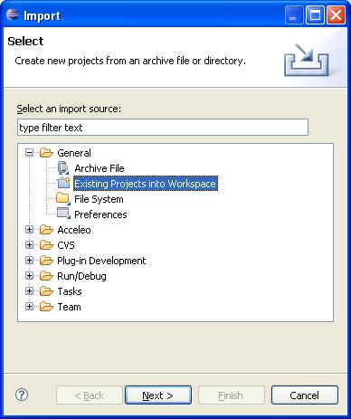
21 Figure 17: Install ModelicaML for Papyrus 2.8 Install OpenModelica Compiler Follow the instruction from to install OpenModelica compiler (OMC) that is used for simulating ModelicaML models. 2.9 Import an Example Projects - Download the example project from the ModelicaML website [11] - Go to File -> Import Existing Project into Workspace - Select the example project - Select the option copy projects into workspace 21

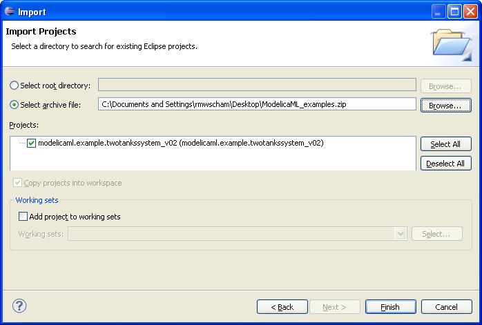
22 Figure 18: Import ModelicaML examples 22
23 References [1] Modelica Association. Modelica: A Unified Object-Oriented Language for Physical Systems Modeling: Language Specification Version 3.0, Sept [2] OMG. OMG Unified Modeling Language TM (OMG UML). Superstructure Version 2.2, February [3] OMG. OMG Systems Modeling Language (OMG SysML ), Version 1.1, November [4] Acceleo, Eclipse Plug-In. [5] Papyrus, [6] Schamai W.. Modelica Modeling Language (ModelicaML) A UML Profile for Modelica, Technical Report 2009:5, EADS IW, Germany, Linkoping University, Sweden, [7] The OpenModelica Project [8] Dymola (Dynamic Modeling Laboratory), Dynamism. [9] MathModelica, [10] Acceleo, Eclipse Plug-In. [11] ModelicaML website: 23
Towards Unified System Modeling and Simulation with ModelicaML: Modeling of Executable Behavior Using Graphical Notations
 Towards Unified System Modeling and Simulation with ModelicaML: Modeling of Executable Behavior Using Graphical Notations Wladimir Schamai 1, Peter Fritzson 2, Chris Paredis 3, Adrian Pop 2 1 EADS Innovation
Execution of UML State Machines Using Modelica
 Execution of UML State Machines Using Modelica Wladimir Schamai 1, Uwe Pohlmann 2, Peter Fritzson 3, Christiaan J.J. Paredis 4, Philipp Helle 1, Carsten Strobel 1 1 EADS Innovation Works, Germany 2 University
An Overview of the SysML-Modelica Transformation Specification
 An Overview of the SysML-Modelica Transformation Specification Christiaan J.J. Paredis 1, Yves Bernard 2, Roger M Burkhart 3. Hans-Peter de Koning 4, Sanford Friedenthal 5, Peter Fritzson 6, Nicolas F
UML 2.0 State Machines
 UML 2.0 State Machines Frederic.Mallet@unice.fr Université Nice Sophia Antipolis M1 Formalisms for the functional and temporal analysis With R. de Simone Objectives UML, OMG and MDA Main diagrams in UML
Towards Unified System Modeling with the ModelicaML UML Profile
 Towards Unified System Modeling with the ModelicaML UML Profile Adrian Pop, David Akhvlediani, Peter Fritzson Programming Environments Lab, Department of Computer and Information Science Linköping University,
On the link between Architectural Description Models and Modelica Analyses Models
 On the link between Architectural Description Models and Modelica Analyses Models Damien Chapon Guillaume Bouchez Airbus France 316 Route de Bayonne 31060 Toulouse {damien.chapon,guillaume.bouchez}@airbus.com
Institutionen för datavetenskap
 Institutionen för datavetenskap Department of Computer and Information Science Final thesis ModelicaML Graphical Modeling Environment Based on Eclipse MDT Papyrus by Imran Hakam LIU-IDA/LITH-EX-A 11/004
Unified Modeling Language 2
 Unified Modeling Language 2 State machines 109 History and predecessors 1950 s: Finite State Machines Huffmann, Mealy, Moore 1987: Harel Statecharts conditions hierarchical (and/or) states history states
AADL Graphical Editor Design
 AADL Graphical Editor Design Peter Feiler Software Engineering Institute phf@sei.cmu.edu Introduction An AADL specification is a set of component type and implementation declarations. They are organized
7 The proposed domain specific language: operational level
 7 The proposed domain specific language: operational level In our methodology, a scenario corresponds to the specification of concrete activities in the pervasive mobile game, including interactions among
Best Practices for Model-Based Systems Engineering
 Seminar / Workshop Best Practices for Model-Based Systems Engineering Hans-Peter Hoffmann, Ph.D. Chief Systems Methodologist, IBM Rational Software hoffmape@us.ibm.com Overview Successfully delivering
EXPRESSING REQUIREMENTS IN MODELICA
 EXPRESSING REQUIREMENTS IN MODELICA Lena Buffoni and Peter Fritzson Linköping University SE-581 83 Linköping Sweden ABSTRACT As cyber-physical systems grow increasingly complex, the need for methodologies
Analysis of the combined use of SCADE and UML 2.x models. Project description. Ramin Hedayati. Member of GRADUIERTENKOLLEG EINGEBETTETE SYSTEME
 Analysis of the combined use of SCADE and UML 2.x s Project description Ramin Hedayati Member of GRADUIERTENKOLLEG EINGEBETTETE SYSTEME 25.11.2007 GESy of combining both s Advantages and disadvatages of
Enterprise Architect. User Guide Series. SysML Models. Author: Sparx Systems. Date: 30/06/2017. Version: 1.0 CREATED WITH
 Enterprise Architect User Guide Series SysML Models Author: Sparx Systems Date: 30/06/2017 Version: 1.0 CREATED WITH Table of Contents Systems Engineering 3 Systems Modeling Language (SysML) 8 SysML Activity
UML PROFILING AND DSL
 UML PROFILING AND DSL version 17.0.1 user guide No Magic, Inc. 2011 All material contained herein is considered proprietary information owned by No Magic, Inc. and is not to be shared, copied, or reproduced
UML for Real-Time Overview
 Abstract UML for Real-Time Overview Andrew Lyons April 1998 This paper explains how the Unified Modeling Language (UML), and powerful modeling constructs originally developed for the modeling of complex
Model driven Engineering & Model driven Architecture
 Model driven Engineering & Model driven Architecture Prof. Dr. Mark van den Brand Software Engineering and Technology Faculteit Wiskunde en Informatica Technische Universiteit Eindhoven Model driven software
UML Profiles Radovan Cervenka
 Unified Modeling Language UML Profiles Radovan Cervenka UML Profiles The mechanisms that allow metaclasses from existing metamodels to be extended to adapt them for different purposes, e.g., to tailor
Ingegneria del Software Corso di Laurea in Informatica per il Management
 Ingegneria del Software Corso di Laurea in Informatica per il Management UML: State machine diagram Davide Rossi Dipartimento di Informatica Università di Bologna State machine A behavioral state machine
SCADE. SCADE Architect System Requirements Analysis EMBEDDED SOFTWARE
 EMBEDDED SOFTWARE SCADE SCADE Architect 19.2 SCADE Architect is part of the ANSYS Embedded Software family of products and solutions, which gives you a design environment for systems with high dependability
ITU-T Z.109. Specification and Description Language Unified modeling language profile for SDL-2010
 International Telecommunication Union ITU-T Z.109 TELECOMMUNICATION STANDARDIZATION SECTOR OF ITU (04/2012) SERIES Z: LANGUAGES AND GENERAL SOFTWARE ASPECTS FOR TELECOMMUNICATION SYSTEMS Formal description
IBM Rational Rhapsody Gateway Add On. Rhapsody Coupling Notes
 Rhapsody Coupling Notes Rhapsody IBM Rational Rhapsody Gateway Add On Rhapsody Coupling Notes License Agreement No part of this publication may be reproduced, transmitted, stored in a retrieval system,
OMG Systems Modeling Language Tutorial May, 2012
 OMG Systems Modeling Language Tutorial May, 2012 Giuseppe Scanniello Giuseppina Casalaro System Engineering Overview System Engineering (SE) is a discipline to deal with complex system realised through
IDERA ER/Studio Software Architect Evaluation Guide. Version 16.5/2016+ Published February 2017
 IDERA ER/Studio Software Architect Evaluation Guide Version 16.5/2016+ Published February 2017 2017 IDERA, Inc. All rights reserved. IDERA and the IDERA logo are trademarks or registered trademarks of
Modeling GAMs with SysML. Automatic GAMs code generation with Model-2-Text tools
 & Automatic GAMs code generation with Model-2-Text tools G. De Tommasi, R. Vitelli October 2011 Page 1 of 23 0. DOCUMENT INFORMATION 0.1 DOCUMENT HISTORY AND VERSION CONTROL REVISION DATE STATUS COMMENTS/MODIFICATIONS
Enterprise Architect Training Courses
 On-site training from as little as 135 per delegate per day! Enterprise Architect Training Courses Tassc trainers are expert practitioners in Enterprise Architect with over 10 years experience in object
Model Driven Development Unified Modeling Language (UML)
") Model Driven Development Unified Modeling Language (UML) An Overview UML UML is a modeling notation standardized by OMG (proposal 1997, ver.1.1 in 1998, ver. 2.0 in 2004) now in 2.4.1 mature based on notations
Model Driven Development Unified Modeling Language (UML) An Overview UML UML is a modeling notation standardized by OMG (proposal 1997, ver.1.1 in 1998, ver. 2.0 in 2004) now in 2.4.1 mature based on notations
News in RSA-RTE 10.0 updated for sprint Mattias Mohlin/Anders Ek, June 2016
 News in RSA-RTE 10.0 updated for sprint 2016.29 Mattias Mohlin/Anders Ek, June 2016 Overview of Improvements (1/3) Now based on Eclipse Mars (4.5.2) New installation scheme RSARTE is now installed as a
1 Overview. 1 Overview. Contents. 1.1 Table of Contents Table of Contents
 1 Overview Contents 1. 1.1 Table of Contents 1 Overview Papyrus is an environment for editing any kind of EMF model, particularly supporting UML 2 ( Unified Modeling Language (UML) version 2.4.1 ) and
News in RSA-RTE 10.1 updated for sprint Mattias Mohlin, November 2017
 News in RSA-RTE 10.1 updated for sprint 2017.46 Mattias Mohlin, November 2017 Overview Now based on Eclipse Neon.3 (4.6.3) Many general improvements since Eclipse Mars Contains everything from RSARTE 10
Institutionen för datavetenskap Department of Computer and Information Science
 Institutionen för datavetenskap Department of Computer and Information Science Final thesis Design and Implementation of the ModelicaML Code Generator Using Acceleo 3.X by Ibrahim Bumin Kara LIU-IDA/LITH-EX-A--15/012
SOFTWARE MODELING AND DESIGN. UML, Use Cases, Patterns, and. Software Architectures. Ki Cambridge UNIVERSITY PRESS. Hassan Gomaa
 SOFTWARE MODELING AND DESIGN UML, Use Cases, Patterns, and Software Architectures Hassan Gomaa George Mason University, Fairfax, Virginia Ki Cambridge UNIVERSITY PRESS Contents Preface P"U
Metaprogrammable Toolkit for Model-Integrated Computing
 Metaprogrammable Toolkit for Model-Integrated Computing Akos Ledeczi, Miklos Maroti, Gabor Karsai and Greg Nordstrom Institute for Software Integrated Systems Vanderbilt University Abstract Model-Integrated
OCL Support in MOF Repositories
 OCL Support in MOF Repositories Joachim Hoessler, Michael Soden Department of Computer Science Technical University Berlin hoessler@cs.tu-berlin.de, soden@cs.tu-berlin.de Abstract From metamodels that
Computation Independent Model (CIM): Platform Independent Model (PIM): Platform Specific Model (PSM): Implementation Specific Model (ISM):
: Platform Independent Model (PIM): Platform Specific Model (PSM): Implementation Specific Model (ISM):") viii Preface The software industry has evolved to tackle new approaches aligned with the Internet, object-orientation, distributed components and new platforms. However, the majority of the large information
viii Preface The software industry has evolved to tackle new approaches aligned with the Internet, object-orientation, distributed components and new platforms. However, the majority of the large information
Getting Started with Papyrus for RealTime v0.9
 1. Introduction This tutorial will show the creation of a simple model using Papyrus for RealTime version 0.9.0 (based on Eclipse Neon). As a precondition to going through this tutorial, you must have
Dominique Blouin Etienne Borde
 Dominique Blouin Etienne Borde dominique.blouin@telecom-paristech.fr etienne.borde@telecom-paristech.fr Institut Mines-Télécom Content Domain specific Languages in a Nutshell Overview of Eclipse Modeling
Institutionen för datavetenskap
 Institutionen för datavetenskap Department of Computer and Information Science Final thesis Validation of ModelicaML Models by Goutham Gatla LIU-IDA/LITH-EX-A 12/061 2012-11-22 Linköpings universitet SE-581
Model Driven Development of Component Centric Applications
 Model Driven Development of Component Centric Applications Andreas Heberle (entory AG), Rainer Neumann (PTV AG) Abstract. The development of applications has to be as efficient as possible. The Model Driven
Modeling the Evolution of Aspect Configurations using Model Transformations
 Modeling the Evolution of Aspect Configurations using Model Transformations Uwe Zdun, Mark Strembeck Institute of Information Systems, New Media Lab Vienna University of Economics, Austria {uwe.zdun mark.strembeck}@wu-wien.ac.at
Applying MDA Modeling to Development of Real-Time Software
 Applying MDA Modeling to Development of Real-Time Software Using a model-driven architecture approach to developing real-time systems offers developers enhanced communication of the requirements from domain
Transforming UML Collaborating Statecharts for Verification and Simulation
 Transforming UML Collaborating Statecharts for Verification and Simulation Patrick O. Bobbie, Yiming Ji, and Lusheng Liang School of Computing and Software Engineering Southern Polytechnic State University
EMF course - PACT. Etienne Borde
 EMF course - PACT Etienne Borde www.etienneborde.fr Objectives Collective software development requires to focus on integration. John develops functionality A; Mike develops functionality B How to ensure
A GrGen.NET solution of the Model Migration Case for the Transformation Tool Contest 2010
 A GrGen.NET solution of the Model Migration Case for the Transformation Tool Contest 2010 Sebastian Buchwald Edgar Jakumeit June 3, 2010 1 Introduction The challenge of the Model Migration Case [1] is
CAMEO SIMULATION TOOLKIT. version 1.0. user guide
 CAMEO SIMULATION TOOLKIT version 1.0 user guide No Magic, Inc. 2011 All material contained herein is considered proprietary information owned by No Magic, Inc. and is not to be shared, copied, or reproduced
News in RSA-RTE 10.1 updated for sprint Mattias Mohlin, January 2018
 News in RSA-RTE 10.1 updated for sprint 2018.03 Mattias Mohlin, January 2018 Overview Now based on Eclipse Neon.3 (4.6.3) Many general improvements since Eclipse Mars Contains everything from RSARTE 10
PisaTel Meeting Roma, 29 novembre 2007
 Istituto di Scienza e Tecnologie dell'informazione A. Faedo Software Engineering Laboratory Tool support for model driven development in practice Antonino Sabetta ISTI-CNR, Pisa PisaTel Meeting Roma, 29
CHAPTER 1. Topic: UML Overview. CHAPTER 1: Topic 1. Topic: UML Overview
 CHAPTER 1 Topic: UML Overview After studying this Chapter, students should be able to: Describe the goals of UML. Analyze the History of UML. Evaluate the use of UML in an area of interest. CHAPTER 1:
JOURNAL OF OBJECT TECHNOLOGY
 JOURNAL OF OBJECT TECHNOLOGY Online at http://www.jot.fm. Published by ETH Zurich, Chair of Software Engineering JOT, 2004 Vol. 3, No. 7, July-August 2004 UML 2 Activity and Action Models Part 5: Partitions
Software Service Engineering
 Software Service Engineering Lecture 4: Unified Modeling Language Doctor Guangyu Gao Some contents and notes selected from Fowler, M. UML Distilled, 3rd edition. Addison-Wesley Unified Modeling Language
A Model Driven Approach for Requirements Engineering of Industrial Automation Systems
 A Model Driven Approach for Requirements Engineering of Industrial Automation Systems Hongchao Ji 1 Oliver Lenord 1 Dieter Schramm 2 1 Bosch Rexroth AG, Germany {hongchao.ji, oliver.lenord}@boschrexroth.de
Compositional Model Based Software Development
 Compositional Model Based Software Development Prof. Dr. Bernhard Rumpe http://www.se-rwth.de/ Seite 2 Our Working Groups and Topics Automotive / Robotics Autonomous driving Functional architecture Variability
Using the VMware vcenter Orchestrator Client. vrealize Orchestrator 5.5.1
 Using the VMware vcenter Orchestrator Client vrealize Orchestrator 5.5.1 You can find the most up-to-date technical documentation on the VMware website at: https://docs.vmware.com/ If you have comments
IncQuery for MagicDraw Quick Start Guide
 IncQuery for MagicDraw Quick Start Guide v1.6.2, June 17, 2018 Table of Contents 1. Installation Guide............................................................. 1 2. Custom Query Evaluation......................................................
News in RSA-RTE 10.2 updated for sprint Mattias Mohlin, May 2018
 News in RSA-RTE 10.2 updated for sprint 2018.18 Mattias Mohlin, May 2018 Overview Now based on Eclipse Oxygen.3 (4.7.3) Contains everything from RSARTE 10.1 and also additional features and bug fixes See
SOFTWARE DESIGN COSC 4353 / Dr. Raj Singh
 SOFTWARE DESIGN COSC 4353 / 6353 Dr. Raj Singh UML - History 2 The Unified Modeling Language (UML) is a general purpose modeling language designed to provide a standard way to visualize the design of a
The etrice Eclipse Project Proposal
 The etrice Eclipse Project Proposal Dipl.-Ing. Thomas Schütz, Protos Software GmbH Eclipse Embedded Day 2010, Stuttgart Agenda Motivation Scope of etrice ROOM Language Codegenerators Middleware Realization
Metamodeling with Metamodels. Using. UML/MOF including OCL
 Metamodeling with Metamodels Using UML/MOF including OCL Introducing Metamodels (Wikipedia) A metamodel is a model of a model An instantiation of metamodel gives a model Metamodeling is the process of
WPS Workbench. user guide. "To help guide you through using the WPS user interface (Workbench) to create, edit and run programs"
 to create, edit and run programs") WPS Workbench user guide "To help guide you through using the WPS user interface (Workbench) to create, edit and run programs" Version: 3.1.7 Copyright 2002-2018 World Programming Limited www.worldprogramming.com
WPS Workbench user guide "To help guide you through using the WPS user interface (Workbench) to create, edit and run programs" Version: 3.1.7 Copyright 2002-2018 World Programming Limited www.worldprogramming.com
Using the VMware vrealize Orchestrator Client
 Using the VMware vrealize Orchestrator Client vrealize Orchestrator 7.0 This document supports the version of each product listed and supports all subsequent versions until the document is replaced by
Enterprise Architect. User Guide Series. Model Navigation
 Enterprise Architect User Guide Series Model Navigation How to navigate repositories? In Sparx Systems Enterprise Architect the Project Browser shows model structure. Model Searches and browsers locate
Integrated Modeling of CPS including Requirements: Open Source MBSE Tools Based on Modelica and UML
 Integrated Modeling of CPS including Requirements: Open Source MBSE Tools Based on Modelica and UML LCCC MBSE Workshop, Lund May 4, 2015 Peter Fritzson peter.fritzson@liu.se Vice Chairman of Modelica Association
RSARTE Icons. Mattias Mohlin Senior Software Architect IBM
 RSARTE Icons Mattias Mohlin Senior Software Architect IBM MODEL ELEMENTS...2 DIAGRAMS...3 VIRTUAL FOLDERS...3 FILES AND FOLDERS...4 OVERLAY ICONS...4 DIAGRAM DECORATOR ICONS...5 This document explains
... SysML version SNAPSHOT User Guide.... Eclipse
 ... SysML version 0.10.1-SNAPSHOT User Guide... Eclipse 2017-01-05 T a b l e o f C o n t e n t s i Table of Contents... 1. Table of Contents...........................................................
Software Architecture in Action. Flavio Oquendo, Jair C Leite, Thais Batista
 Software Architecture in Action Flavio Oquendo, Jair C Leite, Thais Batista Motivation 2 n In this book you can learn the main software architecture concepts and practices. n We use an architecture description
Topic 3 Unified Modeling Language UML. Objective: Student will use UML to represent relationshiops between objects, its structure and dynamics.
 Topic 3 Unified Modeling Language UML Objective: Student will use UML to represent relationshiops between objects, its structure and dynamics. Contents: 1. Structure diagrams 2. Behavior diagrams What
Metamodeling. Janos Sztipanovits ISIS, Vanderbilt University
 Metamodeling Janos ISIS, Vanderbilt University janos.sztipanovits@vanderbilt.edusztipanovits@vanderbilt edu Content Overview of Metamodeling Abstract Syntax Metamodeling Concepts Metamodeling languages
News in RSA-RTE CP1
 IBM Software Group News in RSA-RTE 8.5.1 CP1 Mattias Mohlin, April 2013 2013 IBM Corporation Build A C++ External Library TC can now generate the make file to use for building the library from a CDT project
News in RSA-RTE 10.1 updated for sprint Mattias Mohlin, July 2017
 News in RSA-RTE 10.1 updated for sprint 2017.28 Mattias Mohlin, July 2017 Overview Now based on Eclipse Neon.3 (4.6.3) Many general improvements since Eclipse Mars Contains everything from RSARTE 10 and
UNIT II. Syllabus. a. An Overview of the UML: Visualizing, Specifying, Constructing, Documenting
 UNIT II Syllabus Introduction to UML (08 Hrs, 16 Marks) a. An Overview of the UML: Visualizing, Specifying, Constructing, Documenting b. Background, UML Basics c. Introducing UML 2.0 A Conceptual Model
USING PAPYRUS IN A DESIGN SPACE EXPLORATION TOOLCHAIN CURRENT DEVELOPMENTS AT FLANDERS MAKE
 USING PAPYRUS IN A DESIGN SPACE EXPLORATION TOOLCHAIN CURRENT DEVELOPMENTS AT FLANDERS MAKE Who is Flanders Make? A Flemish research institute whose mission is to strengthen the long-term international
JOURNAL OF OBJECT TECHNOLOGY
 JOURNAL OF OBJECT TECHNOLOGY Online at http://www.jot.fm. Published by ETH Zurich, Chair of Software Engineering JOT, 2003 Vol. 2, No. 6, November-December 2003 UML 2 Activity and Action Models Part 3:
OMG Specifications for Enterprise Interoperability
 OMG Specifications for Enterprise Interoperability Brian Elvesæter* Arne-Jørgen Berre* *SINTEF ICT, P. O. Box 124 Blindern, N-0314 Oslo, Norway brian.elvesater@sintef.no arne.j.berre@sintef.no ABSTRACT:
UNIVERSITY OF OSLO Department of Informatics. Exploration of UML State Machine implementations in Java. Master thesis. Morten Olav Hansen
 UNIVERSITY OF OSLO Department of Informatics Exploration of UML State Machine implementations in Java Master thesis Morten Olav Hansen February 15, 2011 Contents 1 Introduction 8 1.1 Motivation...............................
An Extensible Open Source AADL Tool Environment (OSATE)
") An Extensible Open Source AADL Tool Environment (OSATE) Release 1.0 May 23, 2005 The SEI AADL Team Software Engineering Institute tools@aadl.info 1 Table of Content An Extensible Open Source AADL Tool
An Extensible Open Source AADL Tool Environment (OSATE) Release 1.0 May 23, 2005 The SEI AADL Team Software Engineering Institute tools@aadl.info 1 Table of Content An Extensible Open Source AADL Tool
1 Executive Overview The Benefits and Objectives of BPDM
 1 Executive Overview The Benefits and Objectives of BPDM This is an excerpt from the Final Submission BPDM document posted to OMG members on November 13 th 2006. The full version of the specification will
Contents Contents 1 Introduction Entity Types... 37
 1 Introduction...1 1.1 Functions of an Information System...1 1.1.1 The Memory Function...3 1.1.2 The Informative Function...4 1.1.3 The Active Function...6 1.1.4 Examples of Information Systems...7 1.2
Applying UML Modeling and MDA to Real-Time Software Development
 Michael Benkel Aonix GmbH www.aonix.de michael.benkel@aonix.de Applying UML Modeling and MDA to Real-Time Software Development The growing complexity of embedded real-time applications requires presentation
The Unified Modelling Language. Example Diagrams. Notation vs. Methodology. UML and Meta Modelling
 UML and Meta ling Topics: UML as an example visual notation The UML meta model and the concept of meta modelling Driven Architecture and model engineering The AndroMDA open source project Applying cognitive
with openarchitectureware
 Model-Driven Development with openarchitectureware Markus Völter voelter@acm.orgorg www.voelter.de Sven Efftinge sven@efftinge.de www.efftinge.de Bernd Kolb bernd@kolbware.de www.kolbware.de 2006-7 Völter,
Lab 1: Adding a Rhapsody Model to RMM
 Lab 1: Adding a Rhapsody Model to RMM Objectives After completing this lab, you will be able to: Create an RTC repository workspace and local sandbox Add a Rhapsody model to RMM Link a work item to a change
Deliverable D5.1.1 MAENAD Modeling Workbench
 Grant Agreement 224442 Model-based Analysis & Engineering of Novel Architectures for Dependable Electric Vehicles Report type Report name Deliverable D5.1.1 MAENAD Modeling Workbench Dissemination level
Report on How to Use ALF Action Language and fuml execution/debugging with Moka
 Report on How to Use ALF Action Language and fuml execution/debugging with Moka Coen 6312-Model Driven Software Engineering SAEED SHOARAYE NEJATI (40044525) Matin Maleki (40043676) Concordia University
INTRODUCING A MULTIVIEW SOFTWARE ARCHITECTURE PROCESS BY EXAMPLE Ahmad K heir 1, Hala Naja 1 and Mourad Oussalah 2
 INTRODUCING A MULTIVIEW SOFTWARE ARCHITECTURE PROCESS BY EXAMPLE Ahmad K heir 1, Hala Naja 1 and Mourad Oussalah 2 1 Faculty of Sciences, Lebanese University 2 LINA Laboratory, University of Nantes ABSTRACT:
CHESS Toolset User Guide
 Composition with Guarantees for High -integrity Embedded Software Components Assembly CHESS Toolset User Guide Table of Contents Table of Contents... 2 Introduction... 3 Tool Status... 3 Version 3.0...
Automating Model Composition for Design Verification
 Automating Model Composition for Design Verification Wladimir Schamai (Airbus Group Innovations) Lena Buffoni (Linköping University) Peter Fritzson (Linköping University) Daniel Bouskela (EDF) MODPROD
Analyzing the Product Line Adequacy of Existing Components
 Analyzing the Product Line Adequacy of Existing Components Jens Knodel and Dirk Muthig Fraunhofer Institute for Experimental Software Engineering (IESE), Fraunhofer-Platz 1, D-67663 Kaiserslautern, Germany
IBM Rational Rhapsody Gateway Add On. User Manual
 User Manual Rhapsody IBM Rational Rhapsody Gateway Add On User Manual License Agreement No part of this publication may be reproduced, transmitted, stored in a retrieval system, nor translated into any
UNIT-4 Behavioral Diagrams
 UNIT-4 Behavioral Diagrams P. P. Mahale Behavioral Diagrams Use Case Diagram high-level behaviors of the system, user goals, external entities: actors Sequence Diagram focus on time ordering of messages
Future Directions for SysML v2 INCOSE IW MBSE Workshop January 28, 2017
 Future Directions for SysML v2 INCOSE IW MBSE Workshop January 28, 2017 Sanford Friedenthal safriedenthal@gmail.com 1/30/2017 Agenda Background System Modeling Environment (SME) SysML v2 Requirements Approach
News in RSA-RTE 10.1 updated for sprint Mattias Mohlin, April 2017
 News in RSA-RTE 10.1 updated for sprint 2017.16 Mattias Mohlin, April 2017 Overview Now based on Eclipse Neon.3 (4.6.3) Many general improvements since Eclipse Mars Contains everything from RSARTE 10 and
PAPYRUS FUTURE. CEA Papyrus Team
 PAPYRUS FUTURE CEA ABSTRACT SYNTAX The definition of a DSML abstract syntax in Papyrus is done with the profile editor. It lets define abstract syntax constraints in OCL and Java. Ongoing: Façade [1] lets
Enterprise Architect. User Guide Series. SysML Models. Author: Sparx Systems Date: 26/07/2018 Version: 1.0 CREATED WITH
 Enterprise Architect User Guide Series SysML Models Author: Sparx Systems Date: 26/07/2018 Version: 1.0 CREATED WITH Table of Contents Systems Engineering 5 Parametric Diagram Modeling Assistant 13 Create
IBM Rational Rhapsody Gateway Add On. User Guide
 User Guide Rhapsody IBM Rational Rhapsody Gateway Add On User Guide License Agreement No part of this publication may be reproduced, transmitted, stored in a retrieval system, nor translated into any
Semantics-Based Integration of Embedded Systems Models
 Semantics-Based Integration of Embedded Systems Models Project András Balogh, OptixWare Research & Development Ltd. n 100021 Outline Embedded systems overview Overview of the GENESYS-INDEXYS approach Current
Activity Nets: A UML profile for modeling workflow and business processes
 Activity Nets: A UML profile for modeling workflow and business processes Author: Gregor v. Bochmann, SITE, University of Ottawa (August 27, 2000) 1. Introduction 1.1. Purpose of this document Workflow
OMOptim. OpenModelica Optimization Editor. User Manual. Version 0.9 for OpenModelica January This Description is Extracted
 OMOptim OpenModelica Optimization Editor User Manual Version 0.9 for OpenModelica 1.8.1 January 2012 This Description is Extracted from Chapter 7 of the OpenModelica 1.8.1 User's Guide Copyright by: Open
Towards Generating Domain-Specific Model Editors with Complex Editing Commands
 Towards Generating Domain-Specific Model Editors with Complex Editing Commands Gabriele Taentzer Technical University of Berlin Germany gabi@cs.tu-berlin.de May 10, 2006 Abstract Domain specific modeling
DVT Eclipse IDE. My First Verilog/SystemVerilog Project
 DVT Eclipse IDE My First Verilog/SystemVerilog Project 1 Switch to the DVT Perspective from menu Window > Open Perspective > Other... > DVT The DVT Perspective presents different Views (GUI components)
UNIT V *********************************************************************************************
 Syllabus: 1 UNIT V 5. Package Diagram, Component Diagram, Deployment Diagram (08 Hrs, 16 Marks) Package Diagram: a. Terms and Concepts Names, Owned Elements, Visibility, Importing and Exporting b. Common