UNIT-4 Behavioral Diagrams
|
|
|
- Wendy Johns
- 5 years ago
- Views:
Transcription
1 UNIT-4 Behavioral Diagrams P. P. Mahale
2
3 Behavioral Diagrams Use Case Diagram high-level behaviors of the system, user goals, external entities: actors Sequence Diagram focus on time ordering of messages Collaboration Diagram focus on structural organization of objects and messages State Chart Diagram event driven state changes of system Activity Diagram flow of control between activities
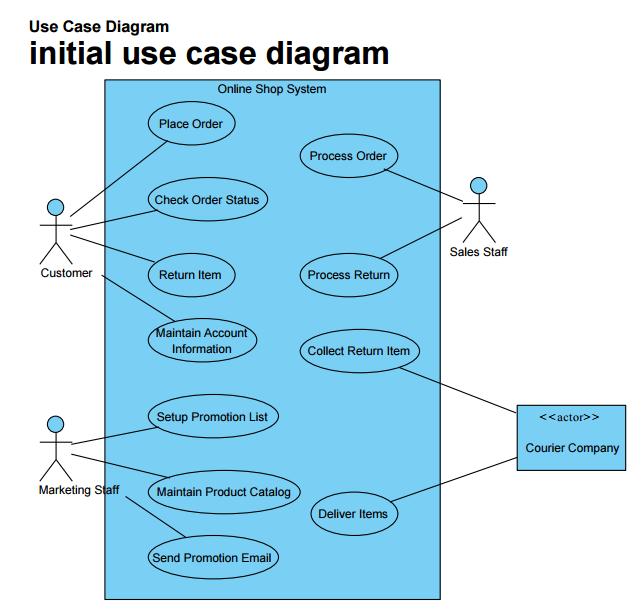
4 Use case Diagram A use case diagram is a diagram that shows a set of use cases and actors and their relationships. Common Properties A use case diagram is just a special kind of diagram and shares the same common properties as do all other diagrams a name and graphical contents that are a projection into a model.
5 Use case Diagram Contents Use case diagrams commonly contain Use cases Actors Dependency, generalization, and association relationships Common Uses 1. To model the context of a system 2. To model the requirements of a system
6 Terms and Concepts Use case Diagram A use case diagram is a diagram that shows a set of use cases and actors and their relationships. Names Every use case must have a name that distinguishes it from other use cases. A name is a textual string. Figure Simple and Path Names
7 Use case Diagram Use Cases and Actors An actor represents a coherent set of roles that users of use cases play when interacting with these use cases. Typically, an actor represents a role that a human, a hardware device, or even another system plays with a system. Figure : Actors
8
9 Use case Diagram Use Cases and Flow of Events A use case describes what a system does but it does not specify how it does it. You can specify the behavior of a use case by describing a flow of events in text clearly enough for an outsider to understand it easily. For example, in the context of an ATM system, you might describe the use case Validate User in the following way: Main flow of events: Exceptional flow of events:
10
11
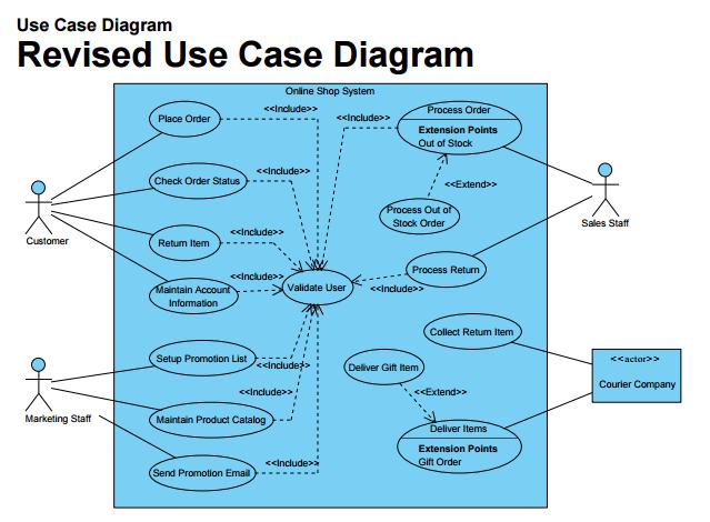
12 Use case Diagram Use Cases and Scenarios A scenario is a specific sequence of actions that illustrates behavior. Use Cases and Collaborations As Figure shows, you can explicitly specify the realization of a use case by a collaboration. Figure : Use Cases and Collaborations
13 Organizing Use Cases Use case Diagram You can organize use cases by grouping them in packages in the same manner in which you can organize classes. Figure : Generalization, Include, and Extend
14 Use case Diagram
15
16
17 Interaction Diagrams Sequence diagrams and collaboration diagrams both of which are called interaction diagrams Sequence Diagrams A sequence diagram emphasizes the time ordering of messages. Figure : Sequence Diagram
18 Interaction Diagrams Sequence & collaboration are call interaction diagram used for modeling dynamic aspect of system It represent interaction, consist of set of objects & their relationships including message 1. Sequence diagram is an interaction diagram that shows time ordering of messages 2. Collaboration diag. is an interaction diagram that shows structural organization of object that send & receive message Model particular flow of control of use case
19 Graphically sequence diagram is table that shows objects arranged in x- axis & messages ordered in increasing time along y-axis Graphically collaboration diagram is collection of vertices & arcs Common properties of interaction diagram : - Share common properties such as name & graphical content - Content of interaction diagram : 1. Object 2. Link 3. Messages - Also contains notes & constraints
20 1. Sequence diagram :- - Shows time ordering - Formed by placing objects that participate in interaction at top of diagram - Place object that initiate interaction at the left & increasingly more subordinate objects to right - Place message that these object send & receive along y-axis in order of increasing time from top to bottom - 2 feature that distinguish from collaboration 1. There is object life line: - It is vertical dashed line that represent existence of an object over a period of time - Object are aliened at top with their life line dawn from top to bottom
21
22 2. There is focus of control - It is tall, thin, rectangular that shows period of time in which an object perform an action - Top of rectangle is aliened with start of action, bottom with completion
23
24 2. Collaboration Diagram - It shows structural organization of object that participate in interaction - It formed by placing object that participate in interaction as vertices in graph - show link that connect these object as arc - Show message that object send & receive
25
26 Collaboration Diagrams Interaction Diagrams A collaboration diagram emphasizes the organization of the objects that participate in an interaction. Figure : Collaboration Diagram
27 Timing Diagrams Interaction Diagrams Timing diagrams are a special representation of interactions that focus on the specific timings of messages sent between objects. You can use timing diagrams to show detailed time constraints on messages or to show when changes occur within lifelines with respect to time. Timing diagrams are most often used with real-time or embedded systems.
28 Interaction Diagrams Figure : Simple timing diagram
29 Interaction Diagrams Figure : Timing diagram with tick marks
30 Interaction Diagrams Figure : Timing diagram with time constraints
31 Interaction Diagrams Figure : Timing diagram with multiple lifelines and messages
32 Interaction Diagrams Figure : Timing diagram using a simpler timeline notation
33 Communication diagrams In UML 2.0 communication diag. is a simplified version of UML 1.x collaboration diag. 4 type of interaction diag.: - Sequence diagram - Communication diagram - Interaction overview diagram - Timing diagram Model interaction between object Communication diag. represent combination of info. Taken from class, sequence, use case diag. describing both static & dynamic behavior of system It shows message flow between objects in OO application & also imply basic association between classes
34
35
36 State chart Diagram
37 State chart Diagram UML has two types of state machines: Behavioral state machines Show the behavior of model elements such as objects. A behavioral state machine represents a specific implementation of an element. Protocol state machines Show the behavior of a protocol. Protocol state machines show how participants may trigger changes in a protocol's state and the corresponding changes in the system (i.e. The new state of the protocol).
38 Behavioral State Machines You can model the behavior of the classifier using states, pseudostates, activities and transitions.
39
40 Protocol State Machines
41 States States model a specific moment in the behavior of a classifier. This moment in time is defined by some condition being true in the classifier. A state is shown as a rectangle with rounded corners. The name of the state is written inside the rectangle. Figure A simple state A state name may be placed outside of the rectangle in a tab notation when showing composite or submachine states Figure : A state with its name in a tab
42 Within the rectangle a state can be divided into compartments as needed. UML defines the following compartments: Figure : A state with compartments
43 UML defines three types of states: 1. Simple states Simplest of all states, they have no substates. All the example states used so far in this section are simple states. 2. Composite states Have one or more regions for substates. A composite state with two or more regions is called orthogonal. 3. Submachine states Semantically equivalent to composite states, submachine states have substates that are contained within a substate machine. Unlike composite states, submachine states are intended to group states, so you can reuse them.
44 Composite States Figure : A composite state with one region Figure: Composite state with composite icon
45

46 Regions A region is shown using a dashed line dividing the decomposition compartment. You may name each region by writing its name within the region's area. Figure shows a composite state with two regions.
47 Submachine state A submachine state is shown in the same rounded rectangle as any other state, except you show the name of the state, followed by a colon (:) followed by the name of the referenced submachine. Figure shows a submachine state.
48 Transitions A transition shows the relationship, or path, between two states or pseudostates. It represents the actual change in the configuration of a state machine as it heads from one state to the next. Transitions are shown as a line between two states, with an arrowhead pointing to the destination state.
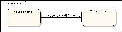
49 Transitions When the action or activity of a state completes, flow of control passes immediately to the next action or activity state. You specify this flow by using transitions to show the path from one action or activity state to the next action or activity state. In the UML, you represent a transition as a simple directed line, as Figure shows. Trigger less transitions may have guard conditions, meaning that such a transition will fire only if that condition is met;
50 trigger [guard] / effect where: Trigger Indicates what condition may cause this transition to occur. The trigger is typically the name of an event, though it may be more complex. Guard Is a constraint that is evaluated when an event is fired by the state machine to determine if the transition should be enabled. Guards should not have any side effects and must evaluate to a Boolean. Guards will always be evaluated before a transition is fired. Effect Specifies an activity that is executed when a transition happens. This activity can be written using operations, attributes, and links of the owning classifier as well as any parameters of the triggering event. An effect activity may explicitly generate events such as sending signals or invoking operations.
51
52
53
54
55
56 Transition types Compound transition: A representation of the change from one complete state machine configuration to another. High-level transition: A transition from a composite state. Internal transition: A transition between states within the same composite state. Completion transition: A transition from a state that has no explicit trigger. When a state finishes its do activities, a completion event is generated.
57 Signal Symbols Transitions may be shown in more detail using explicit icons to show signal sending, signal receipt, and effect activities. Figure A transition-oriented view showing a signal being received
58 Activities An activity represents some functionality that is executed by a system. Each activity has a label showing when the activity executes, and an optional activity expression. An activity is written as: label / activity expression You can write an activity expression using pseudo code: list.append(keystroke) ; print("*") or natural language: record keystroke and show password character UML reserves three activity labels: Entry: Triggers when a state is entered. Exit: Triggers when leaving a state. Do: Executes as long as a state is active.
59 Protocol State Machines Protocol state machines capture the behavior of a protocol, such as HTTP or a challenge response speak easy door. Protocol state machines differ from behavioral state machines in the following ways: entry, exit, and do activities can't be used. States can have invariants. Place invariants in square brackets under the state name.
60 The keyword protocol is placed in curly braces after the state machine name to indicate the state machine is a protocol state machine. Transitions in protocol state machines have a precondition, the trigger, and a post condition. The notation for a protocol transition is as follows: [precondition ] event / [postcondition ] Each transition is associated with zero or one operation on the owning classifier. Figure shows a simplified version of the Simple Mail Transport Protocol (SMTP) protocol.
61
62 Pseudostates Pseudostates are special types of states that represent specific behavior during transitions between regular states.
63
64

65 Event Processing Information within a state machine is conveyed via events. 1. Dispatch As events are triggered, they are added to an event pool. Once added to the event pool, events are sent out for processing by the state machine or are dispatched. The order of event dispatch and processing isn't specified by UML. This allows state machines to impose their own prioritization schemes on events if desired. 2. Deferred Events You can list events that should be deferred from dispatching while in a given state. You show a deferred event by listing the event, followed by a forward slash and the keyword defer within the state. Figure shows a state that defers the cancel event. If the cancel event does fire, it is held in the event pool until the state machine leaves this state.
66
67 Activity Diagrams
68 Terms and Concepts An activity diagram shows the flow from activity to activity. Common Properties An activity diagram is just a special kind of diagram and shares the same common properties as do all other diagrams a name and graphical contents that are a projection into a model. What distinguishes an interaction diagram from all other kinds of diagrams is its content. Contents : Activity states and action states Transitions Objects
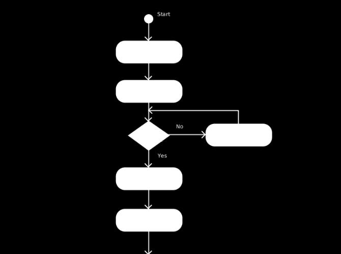
69 Action States and Activity States In the flow of control modeled by an activity diagram, things happen. You might evaluate some expression that sets the value of an attribute or that returns some value. Alternately, you might call an operation on an object, send a signal to an object, or even create or destroy an object. These executable, atomic computations are called action states because they are states of the system, each representing the execution of an action. Figure :Action States
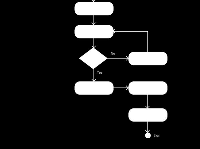
70 Branching You can include a branch, which specifies alternate paths taken based on some Boolean expression. As Figure shows, you represent a branch as a diamond. A branch may have one incoming transition and two or more outgoing ones. On each outgoing transition, you place a Boolean expression, which is evaluated only once on entering the branch
71 Forking and Joining When you are modeling workflows of business processes, you might encounter flows that are concurrent. In the UML, you use a synchronization bar to specify the forking and joining of these parallel flows of control. A synchronization bar is rendered as a thick horizontal or vertical line. For example, consider the concurrent flows involved in controlling an audioanimatronic device that mimics human speech and gestures.
72
73 As Figure shows, a fork represents the splitting of a single flow of control into two or more concurrent flows of control. A fork may have one incoming transition and two or more outgoing transitions, each of which represents an independent flow of control. Join represents the synchronization of two or more concurrent flows of control. A join may have two or more incoming transitions and one outgoing transition
74 Swimlanes Useful, especially when you are modeling workflows of business processes, to partition the activity states on an activity diagram into groups Each group representing the business organization responsible for those activities. In the UML, each group is called a swimlane because, visually, each group is divided from its neighbor by a vertical solid line. A swimlane specifies a flows of activities. Each swimlane has a name unique within its diagram
75
76 Object Flow Objects may be involved in the flow of control associated with an activity diagram As Figure shows, you can specify the things that are involved in an activity diagram by placing these objects in the diagram, connected using a dependency to the activity or transition that creates, destroys, or modifies them. This use of dependency relationships and objects is called an object flow because it represents the participation of an object in a flow of control.
77 In addition to showing the flow of an object through an activity diagram, you can also show how its role, state and attribute values change. As shown in the figure, you represent the state of an object by naming its state in brackets below the object's name. Similarly, you can represent the value of an object's attributes by rendering them in a compartment below the object's name.
78 Figure Object Flow
79
Interactions A link message
 Interactions An interaction is a behavior that is composed of a set of messages exchanged among a set of objects within a context to accomplish a purpose. A message specifies the communication between
Ingegneria del Software Corso di Laurea in Informatica per il Management
 Ingegneria del Software Corso di Laurea in Informatica per il Management UML: State machine diagram Davide Rossi Dipartimento di Informatica Università di Bologna State machine A behavioral state machine
State Machine Diagrams
 State Machine Diagrams Introduction A state machine diagram, models the dynamic aspects of the system by showing the flow of control from state to state for a particular class. 2 Introduction Whereas an
STATE MACHINES. Figure 1: State Machines
 STATE MACHINES Figure 1: State Machines state machine A state machine is a behavior that specifies the sequences of states an object goes through during its lifetime in response to events. Graphically,
Meltem Özturan
 Meltem Özturan www.mis.boun.edu.tr/ozturan/samd 1 2 Modeling System Requirements Object Oriented Approach to Requirements OOA considers an IS as a set of objects that work together to carry out the function.
UNIT-IV BASIC BEHAVIORAL MODELING-I
 UNIT-IV BASIC BEHAVIORAL MODELING-I CONTENTS 1. Interactions Terms and Concepts Modeling Techniques 2. Interaction Diagrams Terms and Concepts Modeling Techniques Interactions: Terms and Concepts: An interaction
UML- a Brief Look UML and the Process
 UML- a Brief Look UML grew out of great variety of ways Design and develop object-oriented models and designs By mid 1990s Number of credible approaches reduced to three Work further developed and refined
UML Fundamental. OutLine. NetFusion Tech. Co., Ltd. Jack Lee. Use-case diagram Class diagram Sequence diagram
 UML Fundamental NetFusion Tech. Co., Ltd. Jack Lee 2008/4/7 1 Use-case diagram Class diagram Sequence diagram OutLine Communication diagram State machine Activity diagram 2 1 What is UML? Unified Modeling
12 Tutorial on UML. TIMe TIMe Electronic Textbook
 TIMe TIMe Electronic Textbook 12 Tutorial on UML Introduction......................................................2.................................................3 Diagrams in UML..................................................3
Unified Modeling Language 2
 Unified Modeling Language 2 State machines 109 History and predecessors 1950 s: Finite State Machines Huffmann, Mealy, Moore 1987: Harel Statecharts conditions hierarchical (and/or) states history states
CS 370 REVIEW: UML Diagrams D R. M I C H A E L J. R E A L E F A L L
 CS 370 REVIEW: UML Diagrams D R. M I C H A E L J. R E A L E F A L L 2 0 1 5 Introduction UML Unified Modeling Language Very well recognized specification for modeling architectures, use cases, etc. UML
UML Diagrams MagicDraw UML Diagrams
 In software development, the diagram is the equivalent of a blueprint. To meet the various needs of many parties, we often need several different blueprints of the same system. Furthermore, every system
What is a Class Diagram? A diagram that shows a set of classes, interfaces, and collaborations and their relationships
 Class Diagram What is a Class Diagram? A diagram that shows a set of classes, interfaces, and collaborations and their relationships Why do we need Class Diagram? Focus on the conceptual and specification
What is a Class Diagram? Class Diagram. Why do we need Class Diagram? Class - Notation. Class - Semantic 04/11/51
 What is a Class Diagram? Class Diagram A diagram that shows a set of classes, interfaces, and collaborations and their relationships Why do we need Class Diagram? Focus on the conceptual and specification
MAHARASHTRA STATE BOARD OF TECHNICAL EDUCATION (Autonomous) (ISO/IEC Certified)
 (ISO/IEC Certified)") Subject Code: 17630 Model Answer Page No: 1 /32 Important Instructions to examiners: 1) The answers should be examined by keywords and not as word-to-word as given in the model answer scheme. 2) The model
Subject Code: 17630 Model Answer Page No: 1 /32 Important Instructions to examiners: 1) The answers should be examined by keywords and not as word-to-word as given in the model answer scheme. 2) The model
LABORATORY 1 REVISION
 UTCN Computer Science Department Software Design 2012/2013 LABORATORY 1 REVISION ================================================================== I. UML Revision This section focuses on reviewing the
MAHARASHTRA STATE BOARD OF TECHNICAL EDUCATION (Autonomous) (ISO/IEC Certified) MODEL ANSWER
 (ISO/IEC Certified) MODEL ANSWER") Important Instructions to examiners: 1) The answers should be examined by key words and not as word-to-word as given in the model answer scheme. 2) The model answer and the answer written by candidate
Important Instructions to examiners: 1) The answers should be examined by key words and not as word-to-word as given in the model answer scheme. 2) The model answer and the answer written by candidate
OMG Modeling Glossary B
 OMG Modeling Glossary B This glossary defines the terms that are used to describe the Unified Modeling Language (UML) and the Meta Object Facility (MOF). In addition to UML and MOF specific terminology,
INTRODUCTION TO UNIFIED MODELING MODEL (UML) & DFD. Slides by: Shree Jaswal
 & DFD. Slides by: Shree Jaswal") INTRODUCTION TO UNIFIED MODELING MODEL (UML) & DFD Slides by: Shree Jaswal What is UML? 2 It is a standard graphical language for modeling object oriented software. It was developed in mid 90 s by collaborative
INTRODUCTION TO UNIFIED MODELING MODEL (UML) & DFD Slides by: Shree Jaswal What is UML? 2 It is a standard graphical language for modeling object oriented software. It was developed in mid 90 s by collaborative
Sequence Diagrams. Massimo Felici. Massimo Felici Sequence Diagrams c
 Sequence Diagrams Massimo Felici What are Sequence Diagrams? Sequence Diagrams are interaction diagrams that detail how operations are carried out Interaction diagrams model important runtime interactions
UML REFERENCE SHEETS. 2013, 2014 Michael Marking; all rights reserved, including moral rights. Web site:
 UML Reference Sheets 2013, 2014 Michael Marking; all rights reserved, including moral rights. Web site: http://www.tatanka.com/ Revision Information This document was last revised 2014.03.02. The current
Lab Manual. Object Oriented Analysis And Design. TE(Computer) VI semester
 VI semester") Lab Manual Object Oriented Analysis And Design TE(Computer) VI semester Index Sr. No. Title of Programming Assignment Page No. 1 2 3 4 5 6 7 8 9 10 Study of Use Case Diagram Study of Activity Diagram Study
Lab Manual Object Oriented Analysis And Design TE(Computer) VI semester Index Sr. No. Title of Programming Assignment Page No. 1 2 3 4 5 6 7 8 9 10 Study of Use Case Diagram Study of Activity Diagram Study
MAHARASHTRA STATE BOARD OF TECHNICAL EDUCATION (Autonomous) (ISO/IEC Certified)
 (ISO/IEC Certified)") Important Instructions to examiners: 1) The answers should be examined by key words and not as word-to-word as given in the model answer scheme. 2) The model answer and the answer written by candidate
Important Instructions to examiners: 1) The answers should be examined by key words and not as word-to-word as given in the model answer scheme. 2) The model answer and the answer written by candidate
Enterprise Architect. User Guide Series. UML Models. Author: Sparx Systems. Date: 30/06/2017. Version: 1.0 CREATED WITH
 Enterprise Architect User Guide Series UML Models Author: Sparx Systems Date: 30/06/2017 Version: 1.0 CREATED WITH Table of Contents UML Models UML Diagrams UML Structural Models Class Diagram Composite
Interaction Modelling: Sequence Diagrams
 Interaction Modelling: Sequence Diagrams Fabrizio Maria Maggi Institute of Computer Science (these slides are derived from the book Object-oriented modeling and design with UML ) Interaction Modelling
Chapter 10. Object-Oriented Analysis and Modeling Using the UML. McGraw-Hill/Irwin
 Chapter 10 Object-Oriented Analysis and Modeling Using the UML McGraw-Hill/Irwin Copyright 2007 by The McGraw-Hill Companies, Inc. All rights reserved. Objectives 10-2 Define object modeling and explain
UNIT 5 - UML STATE DIAGRAMS AND MODELING
 UNIT 5 - UML STATE DIAGRAMS AND MODELING UML state diagrams and modeling - Operation contracts- Mapping design to code UML deployment and component diagrams UML state diagrams: State diagrams are used
Activity Diagram Written Date : September 02, 2016
 Written Date : September 02, 2016 s describe how activities are coordinated to provide a service which can be at different levels of abstraction. Typically, an event needs to be achieved by some operation,
Vidyalankar. T.Y. Diploma : Sem. VI [IF/CM] Object Oriented Modeling and Design Prelim Question Paper Solution
![Vidyalankar. T.Y. Diploma : Sem. VI [IF/CM] Object Oriented Modeling and Design Prelim Question Paper Solution](/thumbs/86/94007497.jpg "Vidyalankar. T.Y. Diploma : Sem. VI [IF/CM] Object Oriented Modeling and Design Prelim Question Paper Solution") T.Y. Diploma : Sem. VI [IF/CM] Object Oriented Modeling and Design Prelim Question Paper Solution Q.1(a) Attempt any THREE of the following [12] Q.1(a) (i) What is modeling? Also state its four features.
T.Y. Diploma : Sem. VI [IF/CM] Object Oriented Modeling and Design Prelim Question Paper Solution Q.1(a) Attempt any THREE of the following [12] Q.1(a) (i) What is modeling? Also state its four features.
APPENDIX M INTRODUCTION TO THE UML
 M INTRODUCTION TO THE UML This appendix, written only for those readers not familiar with the topic, provides a brief introduction, which cannot be considered as exhaustive, to the UML. The UML is a general-purpose
Object-Oriented Software Engineering Practical Software Development using UML and Java. Chapter 8: Modelling Interactions and Behaviour
 Object-Oriented Software Engineering Practical Software Development using UML and Java Chapter 8: Modelling Interactions and Behaviour 8.1 Interaction Diagrams Interaction diagrams are used to model the
UNIT V *********************************************************************************************
 Syllabus: 1 UNIT V 5. Package Diagram, Component Diagram, Deployment Diagram (08 Hrs, 16 Marks) Package Diagram: a. Terms and Concepts Names, Owned Elements, Visibility, Importing and Exporting b. Common
3. Business Process Diagrams
 BPMN Working Draft 3. Business Process Diagrams This section provides a summary of the BPMN graphical objects and their relationships. More details on the concepts will be provided in Business Process
Advanced Software Engineering
 Dev Bhoomi Institute Of Technology LABORATORY MANUAL PRACTICAL INSTRUCTION SHEET EXPERIMENT NO. ISSUE NO. : ISSUE DATE: REV. NO. : REV. DATE : PAGE: 1 LABORATORY Name & Code: Advanced Software Engineering
3. Business Process Diagram Concepts
 PN Working Draft 3. usiness Process Diagram oncepts This section provides a summary of the PN graphical objects and their relationships. ore details on the concepts will be provided in usiness Process
Software Service Engineering
 Software Service Engineering Lecture 4: Unified Modeling Language Doctor Guangyu Gao Some contents and notes selected from Fowler, M. UML Distilled, 3rd edition. Addison-Wesley Unified Modeling Language
Appendix D: Mapping BPMN to BPD Profile
 Appendix D: Mapping BPMN to BPD Profile Members of bpmi.org and the OMG are interested in the unification of the UML 2.0 and BPMN notation for the support of the business user. This draft mapping is in
visualstate Reference Guide
 COPYRIGHT NOTICE Copyright 2000 2014 IAR Systems AB. No part of this document may be reproduced without the prior written consent of IAR Systems. The software described in this document is furnished under
Lesson 11. W.C.Udwela Department of Mathematics & Computer Science
 Lesson 11 INTRODUCING UML W.C.Udwela Department of Mathematics & Computer Science Why we model? Central part of all the activities We build model to Communicate Visualize and control Better understand
Enterprise Architect - UML Dictionary
 Enterprise Architect is an intuitive, flexible and powerful UML analysis and design tool for building robust and maintainable software. This dictionary explains the way in which Enterprise Architect represents
Object-Oriented and Classical Software Engineering
 Slide 16.1 Object-Oriented and Classical Software Engineering Seventh Edition, WCB/McGraw-Hill, 2007 Stephen R. Schach srs@vuse.vanderbilt.edu CHAPTER 16 Slide 16.2 MORE ON UML 1 Chapter Overview Slide
Finite State Machines and Statecharts
 Finite State Machines and Statecharts Hassan Gomaa Dept of Information & Software Engineering George Mason University Reference: H. Gomaa, Chapter 10 - Designing Concurrent, Distributed, and Real-Time
Software Engineering. Page 1. Objectives. Object-Behavioural Modelling. Analysis = Process + Models. Case Study: Event Identification
 Software Engineering Object-Oriented Analysis (State and Interaction Diagrams) James Gain (jgain@cs.uct.ac.za) http://people.cs.uct.ac.za/~jgain 1. Show the object-behaviour design process Objectives 2.
Business Process Modeling. Version /10/2017
 Business Process Modeling Version 1.2.1-16/10/2017 Maurizio Morisio, Marco Torchiano, 2012-2017 3 BP Aspects Process flow Process modeling UML Activity Diagrams BPMN Information Conceptual modeling UML
Exercise Unit 2: Modeling Paradigms - RT-UML. UML: The Unified Modeling Language. Statecharts. RT-UML in AnyLogic
 Exercise Unit 2: Modeling Paradigms - RT-UML UML: The Unified Modeling Language Statecharts RT-UML in AnyLogic Simulation and Modeling I Modeling with RT-UML 1 RT-UML: UML Unified Modeling Language a mix
Stateflow Best Practices By Michael Burke
 Stateflow Best Practices By Michael Burke 2012 The MathWorks, Inc. 1 Topics Background Overview of terms Readability Stateflow hierarchy Modeling tips Basic rules: MAAB style guide 2 Background Objective
MAHARASHTRA STATE BOARD OF TECHNICAL EDUCATION (Autonomous) (ISO/IEC Certified) MODEL ANSWER
 (ISO/IEC Certified) MODEL ANSWER") Important Instructions to examiners: 1) The answers should be examined by key words and not as word-to-word as given in the model answer scheme. 2) The model answer and the answer written by candidate
Important Instructions to examiners: 1) The answers should be examined by key words and not as word-to-word as given in the model answer scheme. 2) The model answer and the answer written by candidate
Modeling with UML. (1) Use Case Diagram. (2) Class Diagram. (3) Interaction Diagram. (4) State Diagram
 Use Case Diagram. (2) Class Diagram. (3) Interaction Diagram. (4) State Diagram") Modeling with UML A language or notation intended for analyzing, describing and documenting all aspects of the object-oriented software system. UML uses graphical notations to express the design of software
Modeling with UML A language or notation intended for analyzing, describing and documenting all aspects of the object-oriented software system. UML uses graphical notations to express the design of software
user.book Page 45 Friday, April 8, :05 AM Part 2 BASIC STRUCTURAL MODELING
 user.book Page 45 Friday, April 8, 2005 10:05 AM Part 2 BASIC STRUCTURAL MODELING user.book Page 46 Friday, April 8, 2005 10:05 AM user.book Page 47 Friday, April 8, 2005 10:05 AM Chapter 4 CLASSES In
Object Oriented Design. Program Design. Analysis Phase. Part 2. Analysis Design Implementation. Functional Specification
 Object Oriented Design Part 2 Analysis Design Implementation Program Design Analysis Phase Functional Specification Completely defines tasks to be solved Free from internal contradictions Readable both
Object-Oriented Modeling. State Machine Diagram. Slides accompanying Version 1.0
 Object-Oriented Modeling State Machine Diagram Slides accompanying UML@Classroom Version 1.0 Business Informatics Group Institute of Software Technology and Interactive Systems Vienna University of Technology
Use Case Model. Static Structure. Diagram. Collaboration. Collaboration. Diagram. Collaboration. Diagram. Diagram. Activity. Diagram.
 !"# $%&' !" #" $%%&&& ! Static Structure Diagram Collaboration Collaboration Diagram Collaboration Diagram Diagram Activity Diagram CRC Card CRC Card UML defines a standard notation for object-oriented
UNIT-II Introduction to UML
 UNIT-II Introduction to UML - P. P. Mahale UML OVERVIEW OF UML :- We need a Modeling Language! We will use the Unified Modeling Language, UML), Provides a standard for artifacts produced during development
Oral Questions. Unit-1 Concepts. Oral Question/Assignment/Gate Question with Answer
 Unit-1 Concepts Oral Question/Assignment/Gate Question with Answer The Meta-Object Facility (MOF) is an Object Management Group (OMG) standard for model-driven engineering Object Management Group (OMG)
Models are used for several purposes. We believe that some of the most important are:
 Course: Objekt orientated programming, extending course Supervisor: Authors: Marc Mikael Karlsson, Sandberg Fredrik Fahlman and Martin Mileros Mälardalens Högskola, spring-2000 UML Contents 1. Introduction...
Basic Structural Modeling. Copyright Joey Paquet,
 Basic Structural Modeling Copyright Joey Paquet, 2000 1 Part I Classes Copyright Joey Paquet, 2000 2 Classes Description of a set of objects sharing the same attributes, operations and semantics Abstraction
Developing Shlaer-Mellor Models Using UML
 Developing Shlaer-Mellor Models Using UML Stephen J. Mellor Neil Lang Project Technology, Inc. 10940 Bigge Street San Leandro, California 94577 (510) 567-0255 http://www.projtech.com This position paper
HCM Modeling Elements. Creating a better understanding of the process model standards used within the MHR-BPS Process Modeling initiative.
 HCM Modeling Elements Creating a better understanding of the process model standards used within the MHR-BPS Process Modeling initiative. HCMS Modeling Element Process This presentation will: o o o o Present
Unified Modeling Language I.
 Unified Modeling Language I. Software engineering Szoftvertechnológia Dr. Balázs Simon BME, IIT Outline Software engineering Modeling Unified Modeling Language (UML) UML Diagrams: Use Case Diagram Activity
BASICS OF UML (PART-2)
") BASICS OF UML (PART-2) 1 USE CASE DIAGRAMS 2 USE CASE DIAGRAMS Use Case Model: a view of a system that emphasizes the behavior as it appears to outside users. A use case model partitions system functionality
BASICS OF UML (PART-2) 1 USE CASE DIAGRAMS 2 USE CASE DIAGRAMS Use Case Model: a view of a system that emphasizes the behavior as it appears to outside users. A use case model partitions system functionality
Software Design Methodologies and Testing. (Subject Code: ) (Class: BE Computer Engineering) 2012 Pattern
 (Class: BE Computer Engineering) 2012 Pattern") Software Design Methodologies and Testing (Subject Code: 410449) (Class: BE Computer Engineering) 2012 Pattern Objectives and outcomes Course Objectives To understand and apply different design methods
Software Design Methodologies and Testing (Subject Code: 410449) (Class: BE Computer Engineering) 2012 Pattern Objectives and outcomes Course Objectives To understand and apply different design methods
Business Process Model and Notation (BPMN)
") Business Process Model and Notation (BPMN) Daniel Brookshier, Distinguished Fellow, No Magic Inc. 1 BPMN Introduction n BPMN 2.0 is an international standard for business process modeling. n Developed
Business Process Model and Notation (BPMN) Daniel Brookshier, Distinguished Fellow, No Magic Inc. 1 BPMN Introduction n BPMN 2.0 is an international standard for business process modeling. n Developed
What s Next. INF 117 Project in Software Engineering. Lecture Notes -Spring Quarter, Michele Rousseau Set 6 System Architecture, UML
 What s Next INF 117 Project in Software Engineering Lecture Notes -Spring Quarter, 2008 Michele Rousseau Set 6 System Architecture, UML Set 6 2 Announcements kreqs should be complete Except minor changes
In This Lecture You Will Learn: Specifying Control. Statechart. Event, State and Transition
 In This Lecture You Will Learn: Specifying Control Lecture 11 How to identify requirements for control in an application How to model object life cycles using statecharts How to develop statechart diagrams
Modeling with Activity Diagram
 Modeling with Activity Diagram The following elements are available in a activity diagram. ActionState SubactivityState InitialState FinalState Synchronization Decision Flow Final Object Flow Signal Accept
CHAPTER 5 CO:-Sketch component diagram using basic notations 5.1 Component Diagram (4M) Sample Component Diagram 5.2 Deployment Diagram (8M)
 Sample Component Diagram 5.2 Deployment Diagram (8M)") CHAPTER 5 CO:-Sketch component diagram using basic notations 5.1 Component Diagram (4M) Sample Component Diagram 5.2 Deployment Diagram (8M) Sample Deployment diagram Component diagrams are different in
CHAPTER 5 CO:-Sketch component diagram using basic notations 5.1 Component Diagram (4M) Sample Component Diagram 5.2 Deployment Diagram (8M) Sample Deployment diagram Component diagrams are different in
Activities Radovan Cervenka
 Unified Modeling Language Activities Radovan Cervenka Activity Model Specification of an algorithmic behavior. Used to represent control flow and object flow models. Executing activity (of on object) is
UML 2.0 State Machines
 UML 2.0 State Machines Frederic.Mallet@unice.fr Université Nice Sophia Antipolis M1 Formalisms for the functional and temporal analysis With R. de Simone Objectives UML, OMG and MDA Main diagrams in UML
SEEM4570 System Design and Implementation. Lecture 10 UML
 SEEM4570 System Design and Implementation Lecture 10 UML Introduction In the previous lecture, we talked about software development life cycle in a conceptual level E.g. we need to write documents, diagrams,
BPMN Getting Started Guide
 Enterprise Studio BPMN Getting Started Guide 2017-09-21 Applies to: Enterprise Studio 3.0.0, Team Server 3.0.0 Table of contents 1 About modeling with BPMN 5 1.1 What is BPMN? 5 1.2 BPMN modeling 5 1.3
CA314 Object Oriented Analysis & Design - 7. File name: CA314_Section_07_Ver01 Author: L Tuohey No. of pages: 16
 CA314 Object Oriented Analysis & Design - 7 File name: CA314_Section_07_Ver01 Author: L Tuohey No. of pages: 16 Table of Contents 7. UML State & Activity Diagrams (see ref 1, Chap. 11, 12)...3 7.1 Introduction...3
Class diagrams. Modeling with UML Chapter 2, part 2. Class Diagrams: details. Class diagram for a simple watch
 Class diagrams Modeling with UML Chapter 2, part 2 CS 4354 Summer II 2015 Jill Seaman Used to describe the internal structure of the system. Also used to describe the application domain. They describe
Course "Softwaretechnik" Book Chapter 2 Modeling with UML
 Course "Softwaretechnik" Book Chapter 2 Modeling with UML Lutz Prechelt, Bernd Bruegge, Allen H. Dutoit Freie Universität Berlin, Institut für Informatik http://www.inf.fu-berlin.de/inst/ag-se/ Modeling,
Business Process Modeling. Version 25/10/2012
 Business Process Modeling Version 25/10/2012 Maurizio Morisio, Marco Torchiano, 2012, 2013 3 BP Aspects Process flow Process modeling UML Activity Diagrams BPMN Information Conceptual modeling UML Class
Data and Process Modelling
 Data and Process Modelling 8a. BPMN - Basic Modelling Marco Montali KRDB Research Centre for Knowledge and Data Faculty of Computer Science Free University of Bozen-Bolzano A.Y. 2014/2015 Marco Montali
Übungsfragen für den Test zum OMG Certified UML Professional (Intermediate) Download
 Download") Die Prüfung zum OCUP (UML Certified UML Professional) besteht aus einem computerbasierten Multiple- Choise-Test, dessen Testfragen aus einem Pool für jeden Kanidaten neu zusammengestellt werden. Die Fragen
Die Prüfung zum OCUP (UML Certified UML Professional) besteht aus einem computerbasierten Multiple- Choise-Test, dessen Testfragen aus einem Pool für jeden Kanidaten neu zusammengestellt werden. Die Fragen
Deriving Model-to-Code Transformation Rules at the Meta- Model Level
 Deriving Model-to-Code Transformation Rules at the Meta- Model Level Lei Liu Emanuel S. Grant Department of Computer Science University of North Dakota liu@cs.und.edu grante@cs.und.edu Abstract: The Unified
SEEM4570 System Design and Implementation Lecture 11 UML
 SEEM4570 System Design and Implementation Lecture 11 UML Introduction In the previous lecture, we talked about software development life cycle in a conceptual level E.g. we need to write documents, diagrams,
Statecharts 1.- INTRODUCTION 1.- INTRODUCTION
 Statecharts INDEX 1.- Introduction 2.- When to use Statecharts 3.- Basic components 4.- Connectors and compound transitions Mª Ángeles Martínez Ibáñez University of Bergen Selected topics in programming
Darshan Institute of Engineering & Technology for Diploma Studies
 REQUIREMENTS GATHERING AND ANALYSIS The analyst starts requirement gathering activity by collecting all information that could be useful to develop system. In practice it is very difficult to gather all
MSc programme (induction week) Department of Informatics INTRODUCTION TO UML
 Department of Informatics INTRODUCTION TO UML") MSc programme (induction week) Department of Informatics INTRODUCTION TO UML Some of this material is based on Bernd Bruegge and Allen H. Dutoit (2009) Object-Oriented Software Engineering: Using UML,
MSc programme (induction week) Department of Informatics INTRODUCTION TO UML Some of this material is based on Bernd Bruegge and Allen H. Dutoit (2009) Object-Oriented Software Engineering: Using UML,
Chapter 2: The Object-Oriented Design Process
 Chapter 2: The Object-Oriented Design Process In this chapter, we will learn the development of software based on object-oriented design methodology. Chapter Topics From Problem to Code The Object and
UML 2.0 UML 2.0. Scott Uk-Jin Lee. Division of Computer Science, College of Computing Hanyang University ERICA Campus
 UML 2.0 Division of Computer Science, College of Computing Hanyang University ERICA Campus Introduction to UML 2.0 UML Unified Modeling Language Visual language for specifying, constructing and documenting
EXTENDED DISTRIBUTED UML-BASED PROTOCOL SYNTHESIS METHOD
 EXTENDED DISTRIBUTED UML-BASED PROTOCOL SYNTHESIS METHOD Jehad Al Dallal Department of Information Science, Kuwait University, Kuwait ABSTRACT Synthesizing specifications for real time applications that
What is use case modeling? 10 - UML Overview. Use-Case diagrams CMPSCI520/620. Rick Adrion 2003 (except where noted) 1
 1") What is use case modeling? 10 - UML Overview use case model a view of a system that emphasizes the behavior as it appears to outside users. A use case model partitions system functionality into transactions
What is use case modeling? 10 - UML Overview use case model a view of a system that emphasizes the behavior as it appears to outside users. A use case model partitions system functionality into transactions
IS 0020 Program Design and Software Tools
 1 IS 0020 Program Design and Software Tools Unified Modeling Language Lecture 13 April 13, 2005 What is UML? 2 The Unified Modelling Language is a standard notation to model [object oriented] systems.
SOFTWARE DESIGN COSC 4353 / Dr. Raj Singh
 SOFTWARE DESIGN COSC 4353 / 6353 Dr. Raj Singh UML - History 2 The Unified Modeling Language (UML) is a general purpose modeling language designed to provide a standard way to visualize the design of a
Structured and Object Oriented Analysis and Design
 RAMRAO ADIK INSTITUTE OF TECHNOLOGY, NERUL Department of Computer Engineering Lab Manual Structured and Object Oriented Analysis and Design 2015-2016 List of Experiments Subject: Structured and object
Introduction to Software Engineering. 6. Modeling Behaviour
 Introduction to Software Engineering 6. Modeling Behaviour Roadmap > Use Case Diagrams > Sequence Diagrams > Collaboration (Communication) Diagrams > Activity Diagrams > Statechart Diagrams Nested statecharts
Activity Nets: A UML profile for modeling workflow and business processes
 Activity Nets: A UML profile for modeling workflow and business processes Author: Gregor v. Bochmann, SITE, University of Ottawa (August 27, 2000) 1. Introduction 1.1. Purpose of this document Workflow
Introduction To UML PART II State Diagrams
 Introduction To UML PART II State Diagrams The behavioral elements show how parts of a UML model change over time. As the system interacts with users and possibly with other systems, the objects that make
Today s Agenda UML. CompSci 280 S Introduction to Software Development. 1.Introduction UML Diagrams. Topics: Reading:
 CompSci 280 S2 2107 Introduction to Software Development Today s Agenda Topics: Introduction Activity Diagram Object interaction Sequence Diagram Reading: Booch G.,The Unified Modeling Language User Guide,
Introduction to Software Engineering. ECSE-321 Unit 9 Architectural Design Approaches
 Introduction to Software Engineering ECSE-321 Unit 9 Architectural Design Approaches Requirement Elicitation Analysis (Software Product Design) Architectural Design Detailed Design Architectural Design
Practical UML - A Hands-On Introduction for Developers
 Practical UML - A Hands-On Introduction for Developers By: Randy Miller (http://gp.codegear.com/authors/edit/661.aspx) Abstract: This tutorial provides a quick introduction to the Unified Modeling Language
Bonita Workflow. Development Guide BONITA WORKFLOW
 Bonita Workflow Development Guide BONITA WORKFLOW Bonita Workflow Development Guide BSOA Workflow v3.0 Software January 2007 Copyright Bull SAS Table of Contents Chapter 1. Overview... 11 1.1 Role of
Chapter No. 2 Class modeling CO:-Sketch Class,object models using fundamental relationships Contents 2.1 Object and Class Concepts (12M) Objects,
 Objects,") Chapter No. 2 Class modeling CO:-Sketch Class,object models using fundamental relationships Contents 2.1 Object and Class Concepts (12M) Objects, Classes, Class Diagrams Values and Attributes Operations
Chapter No. 2 Class modeling CO:-Sketch Class,object models using fundamental relationships Contents 2.1 Object and Class Concepts (12M) Objects, Classes, Class Diagrams Values and Attributes Operations
SOFTWARE ENGINEERING UML FUNDAMENTALS. Saulius Ragaišis.
 SOFTWARE ENGINEERING UML FUNDAMENTALS Saulius Ragaišis saulius.ragaisis@mif.vu.lt Information source Slides are prepared on the basis of Bernd Oestereich, Developing Software with UML: Object- Oriented
UML Start-Up Training UB1
 UML Start-Up Training UB1 Index History Overview Diagrams Use Case Diagram Sequence Diagram Activity Diagram Class Diagram UML This training course is designed with the intention to teach UML in not longer
Chapter 4. Capturing the Requirements. 4th Edition. Shari L. Pfleeger Joanne M. Atlee
 Chapter 4 Capturing the Requirements Shari L. Pfleeger Joanne M. Atlee 4th Edition It is important to have standard notations for modeling, documenting, and communicating decisions Modeling helps us to
UML Notation Guide 3. Contents. Part 1 - Background Introduction 3-5
 UML Notation Guide 3 This guide describes the notation for the visual representation of the Unified Modeling Language (UML). This notation document contains brief summaries of the semantics of UML constructs,