AADL Graphical Editor Design
|
|
|
- Dana Copeland
- 5 years ago
- Views:
Transcription
1 AADL Graphical Editor Design Peter Feiler Software Engineering Institute Introduction An AADL specification is a set of component type and implementation declarations. They are organized in packages. Thus, if you think of the hierarchy of an AADL specification you would expect to see nested packages and component type and implementation declarations in them. It shows nested packages and classes with methods inside them. I call this the library view. This is what the Eclipse Java environment does. This is also what the OSATE environment does. OSATE has been built through EMF and offers an EMF generated object editor. This editor is driven by the AADL meta model expressed in EMF Ecore and has had minimal additional tailoring. The EMF generated object editor also offers a navigational browser showing the library hierarchy. 1

2 At the same time you want to navigate the system instance hierarchy, i.e., when you open the top system and see the subsystems as boxes you want to navigate down through them to see their implementation, i.e., their subcomponents. I call this the instance view. I added such an instance view as a navigational capability to the EMF generated editor. You select a system implementation as the root of your system instance view. Given this root, the instance viewer recursive follows subcomponent declarations to their component implementations and shows their content. In OSATE you can also create an instance model explicitly by identifying the root system implementation. A hierarchy of component instance objects is then created by recursively getting the subcomponents and the subcomponents of their component implementation classifier. You can then open it in the EMF-generated object editor. In this case you navigate the actual instance model. Hierarchical Navigation and Graphical Views A number of systems support hierarchical navigation and graphical views of a layer at a time. These systems include MatLab, MetaH DoME, AcmeStudio, etc. 2
3 In this section I am showing you what we did in the System Verification Manager (SVM). The first figure shows you the navigational browser on the left. It navigates the instance hierarchy. As you select an item on the left you will see its content shown graphically on the right. In this case we selected the top-level system. It is shown as one consisting of two subsystems and how these are connected. You can navigate down the subsystem hierarchy using the navigational browser (MatLab supports this form of navigation) or by selecting a subsystem in the graphical view and clicking the down button (DoME and MatLab also support this form of navigation). In the next figure you see the content of sys2. Note that it shows the ports of sys2 along the edge of the layout (like MatLab and DoME). It shows the connections between the subcomponents and from the enclosing ports to the ports of the subcomponents. 3


4 The next two figures show that you can manipulate the model, i.e., add, change and remove elements of the model and their properties in both the graphical view and in the navigational view. As elements are added they are added once to the underlying model and both views are updated. You can even add elements to the model in only the navigational view with the graphical view closed. In that case there is an issue of synchronization in that the graphical must be updated to reflect changes to the model that have occurred while the graphical view was closed. 4

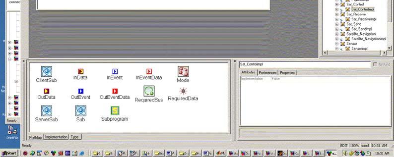
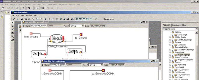
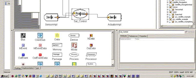
5 In SVM we store the layout information separate from the model, and we store the layout of each system element separately. When the graphical view is opened we have algorithms that update the graphical layout with the model changes. Graphical Nesting We can even consider showing multiple layers of the system in a single graphical view. This is illustrated through the next screen shots. They are from a prototype where the model is an Eclipse EMF generated model (as we have for AADL) and the editor is built with Eclipse GEF. You see the navigational hierarchy browser to the left of the figure. You also see the palette with all the modeling elements. You just drag them into the graphical view to create instances in our case the subcomponents, ports, and connections. The first figure shows a graphical view with 2 layers of nesting, i.e., the content of a system is shown inside its box. One of its systems has its content shown as well. The boxes are shown as having scrollable content, but the boxes could be scalable as well. The second figure shows a subsystem selected in the navigator and its content shown. In this case with only layer of in-place insertion. Note that the layout of the contained elements is the same as in the outer view, just scaled in size. If we offer this capability it may be desirable for the user to be able to control the depth of nesting. Most tools do not offer this capability. 5
6 6 6/10/2005

7 Implementation Issues Where to keep the graphical layout information We have an EMF generated model for AADL. This model is being presented visually through a set of providers that are attached to the model objects. For the object editor that comes with EMF those providers determine the icon and text label to be used (as well as help, the set of properties, etc. to be shown). The GEF takes a similar approach: it has a set of providers that determine what graphical object to draw as graphical representation of a model object. The actual graphical object (figure) drawing method is kept separate from the provider, i.e., the same method can be used by multiple providers. The providers can be stateless (singleton) or stateful. In case of a stateless a single provider is used for all objects of a given class. This is the default for which the generator produces code. You can also tell the generator to provide the provider code as stateful provider. Why is this interesting? In case of the graphical editor we need to maintain position and layout information about the model (in our case the AADL model). This can be done in one of three ways: 7
8 1) Add properties to the model itself about position information. This is what was done in the EMF-GEF workflow example. However this approach does not work well for several reasons: the XML model increases in size and tools not working with graphical presentation do not care about it; An AADL model object may be part of more than one graphical view (e.g., a port is part of an external view of a component and part of its implementation view, or we may want to show the system structure graphically by displaying multiple levels of nesting at any one time). 2) The position information could be kept as state in a stateful provider. This works except that we have to provide special methods to save such information persistently. 3) We define a separate of objects as graphical model objects. Their role is to contain the graphical layout information and a reference to the actual AADL model object. We can define these objects via EMF. By doing so we get the mechanisms for saving it in XML for free including the cross references to the AADL model XML files. I think the network example of the Redbook takes that approach. It is also the approach taken by plugins such as the Omondo plugin for graphically manipulating the EMF meta model. The disadvantage of this approach is that we have to keep the two representations synchronized. [This is the approach the USC student is using to build the graphical editor for OSATE that we have been waiting for and for whom this document was originally written.] (BTW. Here at CMU in the SVM project we also used this approach we provided a method that allowed the graphical view to update itself to the latest model structure, although the model structure may have changed independent of the layout structure.). Persistent storage of the layout information: It can either be stored in a single XML file for all layouts, or we can maintain a folder that contains the collection of layouts as separate XML files. Notice that in the graphical editor you view the system graphically one layer at a time (or a specified number of layers graphically nested). In addition we may have a tree navigator to move through the instance hierarchy quickly. This results in a number of layouts (or layout models if we go with option 3). Those are the ones that could be stored in separate files this is what we did in the SVM project. This way we can have multiple graphical views open at the same time and don t have to worry about coordinating access to the graphical objects and their persistent storage. In the above two examples the user directly manipulates an instance model without a notion of component library. We only have a predeclared set of component types that can be instantiated. AADL Component Libraries and Instance Models In AADL we have a predeclared set of component categories (thread, process, etc.). Using these categories users can define application specific component types and implementations that can be used in component implementations to instantiate subcomponents. AADL specifications are nothing else then a collection of component 8
9 type and implementation declarations, possibly organized into packages. In other words, they are libraries of component descriptions. When developing the AADL language it was decided that instantiation of a model is achieved through tools that there is no explicit language construct to define a model instance; different from MetaH where the application construct defines a model instance. For AADL it is expected that tools do provide instantiation support and OSATE does. You instantiate a model by selecting a system implementation as the root of your model instance. An instance model is then generated by OSATE and stored in the instance model representation for AADL. This instance model representation only exist in XML, not in textual AADL. In textual AADL you can develop an AADL model top-down or bottom-up, or as a mix of top-down and bottom-up. In pure bottom-up you first, declare the component types of the lowest level components. Then, you declare the next layer of components by declaring their component type and their component implementation. You elaborate the component implementation with subcomponents and reference the previously declare component classifiers. In a top-down scenario, you declare the top-level component type and implementation. You specify the subcomponents. You may name the subcomponent classifiers, but they are not declared yet resulting in an error message by the semantic checker. You then declare those component types and implementations. Alternatively, you do not specify the subcomponent classifier until it has been declared as a component type and component implementation. You declare the type and implementation, but without subcomponents, then complete the classifiers of the subcomponents in the enclosing implementation. In a mixed mode, you may have incompletely specified implementations, i.e., implementations without subcomponents or subcomponents without their classifiers. In the next section we explore how to support the concept of user-defined components in a graphical editing environment. We do so by examining how other systems handle this situation. Instance Views and Library Views Depending on the activity users want to operate in one view or the other, or even operate in a blended view in which the user is not aware of the distinction between a library of components and the specific model they are working on. I am going to illustrate some of the different approaches used by different systems. MetaH/DoME, Mathworks Matlab/Simulink, and other systems deal with similar models. Typically you find two views combined: a declarative view and an instance view. The declarative view represents the library of elements to be (re)used in the construction of models in MetaH/DoME called bookshelf, in Matlab library. For AADL this means seeing the collection of packages and the component type and implementation declarations in them. They are reusable in that you refer to them when creating subcomponents. 9
10 At the same time the user primarily wants to work in the instance view. This is what DoME and Simulink present as primary view. In DoME the user places an element from the pallet (e.g., a thread, or process). This results in the creation of a subcomponent. When you try to go inside it, DoME prompts you to select an existing element from the bookshelf (library) as its type or gives you the new choice. New means DoME automatically creates the type and implementation in the bookshelf. Once you opened the subcomponent (process or thread) you can place subcomponents inside it resulting in their placement in the component implementation. Note that if more than one subcomponent points to the same component implementation both will see that subcomponent. The DoME/MetaH Approach The DoME approach is to present primarily an instance view. The reason is that it seems natural and in many cases you will define systems with only one instance of a given type. The MetaH language provides support for this by requiring an explicit instance declaration as part of a MetaH model specification. This it the application <componenttype>.<componentimpl> on <hardwaretype>.<hardwareimpl> construct. It specifies the application root and the hardware root. The first figure shows the top level system (called application in MetaH) opened up. At that level you can only create two items a macro (AADL system with software components) and a system (an AADL system with only platform components). You create them by selecting the category from the left and clicking in the graphical area. This will create these two subcomponents with the respective category, but with no classifier. You change its default name by clicking on the name or opening a property inspector. 10

11 You can then add ports to the component by selecting a port category from the palette and placing it on the component (left or in and right for out). By doing so, behind your back a component type is created and associated with the subcomponent, and the ports are attached to it. The component type name is the same as the subcomponent name. A property inspector can be invoked on the port to edit name and other properties. You can then navigate down one of them by selecting it and clicking on the (green) down arrow. This will open up its content. As shown in the next figure DoME will prompt for that fact and ask whether you want to select from existing (i.e., previously defined) classifiers or create a new one. In this case there are no previous ones, so we will have DoME create the component type and implementation for us. It does so behind our back using the subcomponent name also as component type name and a default component implementation name. We are then placed inside the implementation. When inside the system you can add further subcomponents. You can also add ports to the subcomponents (as before) and connect the subcomponents through their ports by adding connections. When going inside a component the ports of its type are automatically shown on the left and right edge of the diagram. You can connect those ports to a port of one of the subcomponents. You can then go further down the hierarchy and fill out the system. This allows you to create model top-down. You can also proceed by not adding ports to the created components, but by navigating down. In this case the same dialog box comes up and you may select an existing type and implementation or create a new one. You can now select a previously declared classifier. It may have been declared as part of another 11
 shown in the next figure. Its browser lets you select its content according to category (top left).")
12 subcomponent, and this subcomponent is to be of the same type/implementation. Or you may have declared a component through the library view. DoME also has a library view (they call it shelf) shown in the next figure. Its browser lets you select its content according to category (top left). Given the category selection the component types are shown below. When you select one, you see its specification on the middle graphical view. You can add ports to it. On the right you see listed all the places (subcomponent declarations) that refer to the type. Below it you see the implementations listed. You can open the first (automatically created) implementation and add subcomponents the view is the graphical view that we already have seen in the instance navigation. You can also create additional implementations for the same type. The MatLab Approach MatLab also emphasizes the instance view. You create an empty model. You open a library palette. You drag things from the library palette onto the graphical view to create an instance of the block. The figure below shows the palette on the bottom left. It contains built-in building blocks and specialized blocks. Users can create reusable library blocks through the graphical view. You create a library model instead of a regular model. The library models can be added to the library palette and used from there by drag n drop. Or they used by opening the library model and dragging user-defined blocks from the graphical window of the file 12


13 containing the library blocks. In AADL terminology you would see process, thread, etc. in the palette, and the component types defined by the user in library files In MatLab you start with a model file. This represents a model instance. You navigate down the hierarchy both through a hierarchical navigator (not shown but it looks like the tree navigator of the EMF generated object editor) and by double clicking on a block that contains blocks. This results in its content being shown in a separate window or in-place. This is shown in the top left window and the bottom right. If the block you click on is actually a reference to a library block you are not aware that you are now inside a library block unless you want to make a change to it. If you want to make a change Matlab tells you that you are in a library block. You can then break the library link and make local modifications. It remembers that you broke the library link and lets you later reconnect to the library by moving your local change to the library or going back to the library version. You have to do extra work if you want to hold on to your change as a separate version in the library (it is up to you to copy it into the library file and then create the reference by dragging it back into the model). You can also go to the library itself by right clicking and invoking the goto library block command. The open library file with reusable blocks is shown as the top right window. 13
14 MatLab also supports configurable subsystem blocks. That is shown (not very well visually) in the top right window. The blue block actually represents the selection block (configurable subsystem in Matlab terms) which itself points to the other blocks with one as the default selection. If you have a reference to it in your model you get the default selection but you can change it to another variant. What does that mean in terms of AADL? Well, the configurable subsystem block represents a component type, the variants selectable via it represent component implementations. Creating a reference in a model (or inside one of the variants in the library) corresponds to creating subcomponents in a component implementation and specifying the classifier with the type and one or another implementation. The GME Approach The Generic Modeling Environment (GME) of Vanderbilt U. takes yet another approach. In July/Aug 2003 I created a quick prototype of AADL in it. The results of it are shown in the next two figures. GME handles certain things well. One is that it has a built-in notion of component types and component implementation. It understands that implementations can inherit the interface aspect from the type. It also gave me the idea of how to show the modes of AADL graphically modes are just sets that specify a mapping onto a set of subcomponents and connections. It allows you to select a mode and then all components and connections in the graphical view not part of the selected mode are grayed out. In the generated GME we automatically get a library view shown on the right in the figure below. We also have a graphical view and a palette. The palette only has the component categories shown at the bottom. With them you define the specific component types. Those are then shown in the hierarchical browser. From those types you create subtypes to represent implementations by dragging the type within the hierarchy navigator and holding down a key. If you then open the implementation in the graphical view you can then place things into it shown on the left. Typically you want to create subcomponents by dragging an implementation from the navigator and holding down another key to get the instance. You could also drag a category symbol from the palette, but there is no built-in operation to later refine it to a specific classifier. Many of the constraints as to whether something can be placed in a certain place can be expressed by an OCL-like notation although recently they seem to be moving away from that. The first figure shows a component type selected in the navigator, and a port added to it in the graphical view. The second figure shows the implementation of the top-level system, and by double clicking on one of the subcomponents the opened window (could also be in-place) of that systems content. In other words the graphical view allows us to navigate the instance hierarchy, while the navigator presents the library hierarchy. 14

15 15 6/10/2005
16 I created the satellite example using this editor. The frustrating part was that it did not provide an automatic way of creating the component type and implementation as I was trying to create the system top down. It also did not have support for turning a generic process into one with the type or implementation selected. Instead I had to define the types (and implementations) before I could use them in another implementation to create subcomponents, in other words develop the system bottom up. It was also difficult to see the system hierarchy in the library view. There was no view that sorted component types in the library according to the hierarchy or let you view the hierarchy for a selected implementation (as discussed earlier for the OSATE/EMF object editor). The ACME Studio Approach ACME Studio is based on ACME. ACME originally was intended to be an ADL interchange language. As such you can define a family or style to represent your ADL. I had done that for MetaH. As you load that style into ACME Studio you can then define your own graphical symbols for it and you have an editor for MetaH. That editor is shown in the figure below. It is now based on Eclipse. On the right you see a graphical view. You can also switch to a textual view of the same model. At the top left is a Type browser that lets you see collections of component types in a family, i.e., a library view into an AADL package. At the bottom left you have the outline view. It presents an Instance view. However, it makes visible some specific elements of ACME that are a reflection of the fact that it is a meta notation as well you have to create and see representations that themselves must contain systems to represent the concept of a component implementation. To the left of the graphical view you have the palette that shows both the generic categories (in this case the ACME primitives) and specific families [sometimes also called styles] (in this case the MetaH primitives). Users would define component types that in ACME terms are extensions of the MetaH primitives (that themselves are extensions of ACME primitives). The user defined component types can be defined as families and as such also made available in the palette. In other words, the family concept is on one hand used to introduce AADL as a domain specific language, on the other hand it can be used to organize user-defined components into libraries (AADL packages). Similarly, the extension concept on one hand has been used to introduce the AADL specific component categories, on the other hand it is used to introduce component types/implementations (as extensions of the categories), and AADL extends to component types and implementations. Thus, the hard part is for the user to figure out when they are working at what meta-level and when at the instance level. 16

17 17 6/10/2005
18 The AADL Approach to Library and Instance Views We will want both the declarative view (library) and the instance view. We want to pick up the good ideas from each of the systems shown before, but avoid their pitfalls. We can do that with a graphical layout view for components and their connectivity. This view shows the content of a selected component implementation or the component implementation classifier of a selected subcomponent or component instance. The selection occurs either in a navigational browser or in the graphical view. The difference is in the navigational browser (labeled as package explorer in the figures below). The navigational browser is opened on an AADL specification, i.e., a collection of package and component type/impl declarations. In this case we are in a library view. In this library view we can create component types by selecting the navigational root (anonymous namespace) or by selecting a package. The graphical view pane is empty or shows the content of the AADL spec or package. We create a component type by dragging component category icons from the palette into the graphical view. We can add ports from the palette. By default one implementation is added. We can add implementations by a command on the selected component type explicitly. This is shown in the figure below. 18

19 When a component implementation is selected in the navigational browser, its content is shown in the graphical view. It may be empty, may show the ports defined for its type, or may have subcomponents and connections included. In this case we can add subcomponents without classifiers by dragging the component category icon from the palette. Those subcomponents can later be refined by dropping a specific component type or implementation onto its symbol in the graphical view. An existing classifier may be selected as well and dropped into the graphical view. There are several options for doing so: Extend the palette to include collections (AADL packages) of user defined component type and implementations; Have an additional view that is similar to the library navigational browser for the purpose of selection and drag/drop. Reuse the library navigational browser for that role in this case we need to operate modal (mode buttons or holding special keys) to distinguish between navigating to a new component and selecting an item for inclusion/drag n drop. The library view with a selected implementation is shown in the figure below. In this figure the classifier selection mechanism is assumed to be modal on the package explorer. 19

20 These views are useful for creating components individually, top-down, bottom-up, or mixed. When navigating down in the graphical view we navigate to the component implementation of the selected subcomponent. A navigation stack allows us to walk back up the hierarchy (in quotes because it just walks back the navigation path). As discussed earlier, even when operating on an AADL specification we can offer a navigational instance view on this library for a selected component implementation. This can be done by selecting a component implementation in the navigational browser and switching to the instance view. This is shown in the next figure. In this view the user can see the system hierarchy as a tree in the navigational browser and navigate it either via the browser or via down in the graphical view. Finally, we can create an instance model and use the navigational browser on it in the left panel. Its view looks similar to the one above. The main difference is in the action taken when modifications are made. In other words, they may be local to that instance model and not affect other instance models. Managing and Propagating Change 20
21 Things get tricky when modifications are made. What does it mean when a subcomponent is added to an implementation? Is the intention to make it to the library entry or is it a modification to a specific model instance? NOTE: These issues are not really specific to providing a graphical editing front-end, but must be addressed in any kind of AADL environment that supports AADL models in multiple files, and the explicit generation and maintenance of instance models from AADL specifications. If the modified implementation is referenced by only one component instance this is not an issue. If it is referenced by only one subcomponent, then have to deal with the fact that we may have more than one instance model that has been created and they need to be updated. This is already being addressed in OSATE Release 1.0 where the instance model is regenerated if a component implementation used by an instance model has changed. If more than one reference exist to the component implementation we need to give the user a choice (as is done in MatLab). The user needs to indicate that they want a library change with appropriate change propagation, or they want a new variant. In the latter case, we create a new implementation with the reflected change and have the subcomponent point to it. If the change is to a component type or implementation in the anonymous name space only component declarations in the anonymous name can be affected. If it is to declarations in packages and other component declarations reference these packages then we need to propagate across packages. (OSATE 1.0 keeps packages in separate files and understands that declarations in AADL specs that are not in packages are in the anonymous namespace.) We also need to take into account the existence of team support when managing propagation of change. A user may be responsible for only those parts of a model that they check out of a version control system into their workspace. In other words, they may be responsible for only a subset of the instance models generated from components in an AADL package. Changes to the AADL package are then placed in the repository as a new version. Other instance models have been generated against the old version and are still consistent with it. Someone else will later determine when to upgrade the remaining instance models to the new version of a package. He same scenario applies if a package is modified and it is used by other packages. Either the original developer is made responsible for the collection of packages, or a subset, or only for making the change to the package itself. Again, other packages that depend on (make use of) this package will be against the old version. Upgrade to the new version can be performed either in a single change assignment (the original developer needs to deal with all dependent packages), or upgrading other packages is assigned to others separately. In essence we are reliving the process of evolving programs that have been modularized. 21
22 Editing AADL Properties AADL properties are interesting as they can be declared in one place in the model and apply to others. On one hand there is the inheritance of property values from types and implementations to their extensions, from types to implementations, implementations, to subcomponents, to instances. On the other hand there is the contained property association that allows a property value to be attached to a contained component and specify a value that refers to another component in the hierarchy. An example of its use that specification of bindings. OSATE has a property viewer that understands the inheritance of property values. In other words, it shows the property value, whether inherited or locally declared. Currently this is only a viewer, i.e., the values cannot be changed. However, the property value can be changed through the properties view. Additional property associations to overwrite inherited values can be created by placing them with the desired part of the object model. An appropriate way of extending an editing system to handle AADL properties is for the AADL property viewer to indicate whether a property is locally declared or inherited at least when the user wants to modify its value. The user should be able to click on the value and get it handed in a dialog in text form. When changed it is parsed and translated into the model representation. In case of a locally declared property association we would change the existing value to a new one. In the other case we want the user to be aware that they either want to overwrite an inherited value by the one they specify, or that they want to modify the inherited value in its original location. In the latter case we can offer a function to navigate to the original location of declaration. Thus, the user is aware as to how global a change they make. (OSATE 1.0 has such navigation capability to go from a subcomponent or port to the classifier associated with it, from connections to the ports they point to, form instance model elements to the elements in the declarative model they are derived from etc.) The latter change would affect other parts of the model that inherit the same value in particular instance models that cache property values in the instance model would need to be updated. 22
An Extensible Open Source AADL Tool Environment (OSATE)
") An Extensible Open Source AADL Tool Environment (OSATE) Release 1.0 May 23, 2005 The SEI AADL Team Software Engineering Institute tools@aadl.info 1 Table of Content An Extensible Open Source AADL Tool
An Extensible Open Source AADL Tool Environment (OSATE) Release 1.0 May 23, 2005 The SEI AADL Team Software Engineering Institute tools@aadl.info 1 Table of Content An Extensible Open Source AADL Tool
An Extensible Open Source AADL Tool Environment (OSATE)
") An Extensible Open Source AADL Tool Environment (OSATE) Release 0.3.0 Oct 5, 2004 The SEI AADL Team Software Engineering Institute tools@aadl.info 1 Table of Content An Extensible Open Source AADL Tool
An Extensible Open Source AADL Tool Environment (OSATE) Release 0.3.0 Oct 5, 2004 The SEI AADL Team Software Engineering Institute tools@aadl.info 1 Table of Content An Extensible Open Source AADL Tool
AADL Meta Model & XML/XMI
 AADL Meta Model & XML/XMI Peter Feiler Software Engineering Institute phf@sei.cmu.edu Meta Modeling Approach Declarative AADL Model AADL Instance Model Outline 2 XMI/XML Based Tool Interoperability Textual
Investigation of System Timing Concerns in Embedded Systems: Tool-based Analysis of AADL Models
 Investigation of System Timing Concerns in Embedded Systems: Tool-based Analysis of AADL Models Peter Feiler Software Engineering Institute phf@sei.cmu.edu 412-268-7790 2004 by Carnegie Mellon University
IDERA ER/Studio Software Architect Evaluation Guide. Version 16.5/2016+ Published February 2017
 IDERA ER/Studio Software Architect Evaluation Guide Version 16.5/2016+ Published February 2017 2017 IDERA, Inc. All rights reserved. IDERA and the IDERA logo are trademarks or registered trademarks of
Metamodeling. Janos Sztipanovits ISIS, Vanderbilt University
 Metamodeling Janos ISIS, Vanderbilt University janos.sztipanovits@vanderbilt.edusztipanovits@vanderbilt edu Content Overview of Metamodeling Abstract Syntax Metamodeling Concepts Metamodeling languages
Teiid Designer User Guide 7.5.0
 Teiid Designer User Guide 1 7.5.0 1. Introduction... 1 1.1. What is Teiid Designer?... 1 1.2. Why Use Teiid Designer?... 2 1.3. Metadata Overview... 2 1.3.1. What is Metadata... 2 1.3.2. Editing Metadata
EMF course - PACT. Etienne Borde
 EMF course - PACT Etienne Borde www.etienneborde.fr Objectives Collective software development requires to focus on integration. John develops functionality A; Mike develops functionality B How to ensure
Managing Content with AutoCAD DesignCenter
 Managing Content with AutoCAD DesignCenter In This Chapter 14 This chapter introduces AutoCAD DesignCenter. You can now locate and organize drawing data and insert blocks, layers, external references,
Comparing graphical DSL editors
 Comparing graphical DSL editors AToM 3 vs GMF & MetaEdit+ Nick Baetens Outline Introduction MetaEdit+ Specifications Workflow GMF Specifications Workflow Comparison 2 Introduction Commercial Written in
Plug-in Development for the Open Source AADL Tool Environment Part 3: Generation & External Models
 Plug-in Development for the Open Source AADL Tool Environment Part 3: Generation & External Models Peter Feiler / Aaron Greenhouse Software Engineering Institute (phf / aarong)@sei.cmu.edu 412-268- (7790
6.001 Notes: Section 8.1
 6.001 Notes: Section 8.1 Slide 8.1.1 In this lecture we are going to introduce a new data type, specifically to deal with symbols. This may sound a bit odd, but if you step back, you may realize that everything
A Quick Tour GETTING STARTED WHAT S IN THIS CHAPTER?
 1 A Quick Tour WHAT S IN THIS CHAPTER? Installing and getting started with Visual Studio 2012 Creating and running your fi rst application Debugging and deploying an application Ever since software has
Dominique Blouin Etienne Borde
 Dominique Blouin Etienne Borde dominique.blouin@telecom-paristech.fr etienne.borde@telecom-paristech.fr Institut Mines-Télécom Content Domain specific Languages in a Nutshell Overview of Eclipse Modeling
ArtOfTest Inc. Automation Design Canvas 2.0 Beta Quick-Start Guide
 Automation Design Canvas 2.0 Beta Quick-Start Guide Contents Creating and Running Your First Test... 3 Adding Quick Verification Steps... 10 Creating Advanced Test Verifications... 13 Creating a Data Driven
Architectural Design
 Architectural Design Topics i. Architectural design decisions ii. Architectural views iii. Architectural patterns iv. Application architectures Chapter 6 Architectural design 2 PART 1 ARCHITECTURAL DESIGN
UML Fundamental. OutLine. NetFusion Tech. Co., Ltd. Jack Lee. Use-case diagram Class diagram Sequence diagram
 UML Fundamental NetFusion Tech. Co., Ltd. Jack Lee 2008/4/7 1 Use-case diagram Class diagram Sequence diagram OutLine Communication diagram State machine Activity diagram 2 1 What is UML? Unified Modeling
Telerik Corp. Test Studio Standalone & Visual Studio Plug-In Quick-Start Guide
 Test Studio Standalone & Visual Studio Plug-In Quick-Start Guide Contents Create your First Test... 3 Standalone Web Test... 3 Standalone WPF Test... 6 Standalone Silverlight Test... 8 Visual Studio Plug-In
Topics in Object-Oriented Design Patterns
 Software design Topics in Object-Oriented Design Patterns Material mainly from the book Design Patterns by Erich Gamma, Richard Helm, Ralph Johnson and John Vlissides; slides originally by Spiros Mancoridis;
6.001 Notes: Section 6.1
 6.001 Notes: Section 6.1 Slide 6.1.1 When we first starting talking about Scheme expressions, you may recall we said that (almost) every Scheme expression had three components, a syntax (legal ways of
COMMUNITIES USER MANUAL. Satori Team
 COMMUNITIES USER MANUAL Satori Team Table of Contents Communities... 2 1. Introduction... 4 2. Roles and privileges.... 5 3. Process flow.... 6 4. Description... 8 a) Community page.... 9 b) Creating community
6.001 Notes: Section 1.1
 6.001 Notes: Section 1.1 Slide 1.1.1 This first thing we need to do is discuss the focus of 6.001. What is this course all about? This seems quite obvious -- this is a course about computer science. But
An Implementation of the Behavior Annex in the AADL-toolset Osate2
 2011 16th IEEE International Conference on Engineering of Complex Computer Systems An Implementation of the Behavior Annex in the AADL-toolset Osate2 Gilles Lasnier, Laurent Pautet Inst. TELECOM - TELECOM
Error Model Meta Model and Plug-in
 Error Model Meta Model and Plug-in Peter Feiler phf@sei.cmu.edu May 28, 2007 The error model plug-in implements the Error Model Annex language extension. It provides all the front-end components, i.e.,
1. Installing R4E 1. 1) Provision Software Sites 2. 2) Install Version Control System Features 3. 3) Install R4E feature 4. 4) Install Versions
 Provision Software Sites 2. 2) Install Version Control System Features 3. 3) Install R4E feature 4. 4) Install Versions") R4E Documentation 1. Installing R4E 1. 1) Provision Software Sites 2. 2) Install Version Control System Features 3. 3) Install R4E feature 4. 4) Install Versions Connectors 2. Getting Started 1. Overview
R4E Documentation 1. Installing R4E 1. 1) Provision Software Sites 2. 2) Install Version Control System Features 3. 3) Install R4E feature 4. 4) Install Versions Connectors 2. Getting Started 1. Overview
Function. Description
 Function Check In Get / Checkout Description Checking in a file uploads the file from the user s hard drive into the vault and creates a new file version with any changes to the file that have been saved.
Creating Universally Designed Word 2013 Documents - Quick Start Guide
 Creating Universally Designed Word 2013 Documents - Quick Start Guide Overview Creating accessible documents ones that work well with all sorts of technology can be a daunting task. The purpose of this
AADL v2.1 errata AADL meeting Sept 2014
 AADL v2.1 errata AADL meeting Sept 2014 Software Engineering Institute Carnegie Mellon University Pittsburgh, PA 15213 V2.1 Errata Additional applies to allowances Inconsistency in reference/applies to
Learning Objectives. Description. Your AU Expert(s) Trent Earley Behlen Mfg. Co. Shane Wemhoff Behlen Mfg. Co.
 Trent Earley Behlen Mfg. Co. Shane Wemhoff Behlen Mfg. Co.") PL17257 JavaScript and PLM: Empowering the User Trent Earley Behlen Mfg. Co. Shane Wemhoff Behlen Mfg. Co. Learning Objectives Using items and setting data in a Workspace Setting Data in Related Workspaces
PL17257 JavaScript and PLM: Empowering the User Trent Earley Behlen Mfg. Co. Shane Wemhoff Behlen Mfg. Co. Learning Objectives Using items and setting data in a Workspace Setting Data in Related Workspaces
Working with the RTF Generator
 Using EA Working with the RTF Generator by Dermot O Bryan All material Sparx Systems 2008 Sparx Systems 2008 Page 1 Trademarks Microsoft, Microsoft Word are trademarks or registered trademarks of the Microsoft
IBM TRIRIGA Application Platform Version 3 Release 4.2. Object Migration User Guide
 IBM TRIRIGA Application Platform Version 3 Release 4.2 Object Migration User Guide Note Before using this information and the product it supports, read the information in Notices on page 41. This edition
Moving to Altium Designer from Protel 99 SE. Contents
 Moving to Altium Designer from Protel 99 SE Contents Design Database Become a Design Workspace & Projects Importing a 99 SE Design Database Creating the Altium Designer Project(s) Manually Adding and Removing
Introduction to Autodesk VaultChapter1:
 Introduction to Autodesk VaultChapter1: Chapter 1 This chapter provides an overview of Autodesk Vault features and functionality. You learn how to use Autodesk Vault to manage engineering design data in
EDITING AN EXISTING REPORT
 Report Writing in NMU Cognos Administrative Reporting 1 This guide assumes that you have had basic report writing training for Cognos. It is simple guide for the new upgrade. Basic usage of report running
Chapter 1 GETTING STARTED. SYS-ED/ Computer Education Techniques, Inc.
 Chapter 1 GETTING STARTED SYS-ED/ Computer Education Techniques, Inc. Objectives You will learn: The IDE: Integrated Development Environment. MVC: Model-View-Controller Architecture. BC4J: Business Components
Creating Buttons and Pop-up Menus
 Using Fireworks CHAPTER 12 Creating Buttons and Pop-up Menus 12 In Macromedia Fireworks 8 you can create a variety of JavaScript buttons and CSS or JavaScript pop-up menus, even if you know nothing about
Bucknell University Digital Collections. LUNA Insight User Guide February 2006
 Bucknell University Digital Collections LUNA Insight User Guide February 2006 User Guide - Table of Contents Topic Page Number Installing Insight. 2-4 Connecting to Insight 5 Opening Collections. 6 Main
Compartment and Access
 Compartment and Access Page 1 Preface Using This Guide What's New? Getting Started Entering the Workbench Set Correct Working Units and Grid Saving Documents User Tasks Creating/Modifying Wall Systems
Teiid Designer User Guide 7.7.0
 Teiid Designer User Guide 1 7.7.0 1. Introduction... 1 1.1. What is Teiid Designer?... 1 1.2. Why Use Teiid Designer?... 2 1.3. Metadata Overview... 2 1.3.1. What is Metadata... 2 1.3.2. Editing Metadata
Dreamweaver is a full-featured Web application
 Create a Dreamweaver Site Dreamweaver is a full-featured Web application development tool. Dreamweaver s features not only assist you with creating and editing Web pages, but also with managing and maintaining
Mobile Application Workbench. SAP Mobile Platform 3.0 SP02
 SAP Mobile Platform 3.0 SP02 DOCUMENT ID: DC-01-0302-01 LAST REVISED: January 2014 Copyright 2014 by SAP AG or an SAP affiliate company. All rights reserved. No part of this publication may be reproduced
ModelicaML: Getting Started Issue April 2012
 ModelicaML: Getting Started Issue 1.6.5 13. April 2012 Wladimir Schamai EADS Innovation Works (Hamburg, Germany) Linkoping University (Linkoping, Sweden) Abstract: This document provides a short introduction
BEAWebLogic. Integration. Transforming Data Using XQuery Mapper
 BEAWebLogic Integration Transforming Data Using XQuery Mapper Version: 10.2 Document Revised: March 2008 Contents Introduction Overview of XQuery Mapper.............................................. 1-1
Tips and Techniques for Designing the Perfect Layout with SAS Visual Analytics
 SAS2166-2018 Tips and Techniques for Designing the Perfect Layout with SAS Visual Analytics Ryan Norris and Brian Young, SAS Institute Inc., Cary, NC ABSTRACT Do you want to create better reports but find
Part I. Integrated Development Environment. Chapter 2: The Solution Explorer, Toolbox, and Properties. Chapter 3: Options and Customizations
 Part I Integrated Development Environment Chapter 1: A Quick Tour Chapter 2: The Solution Explorer, Toolbox, and Properties Chapter 3: Options and Customizations Chapter 4: Workspace Control Chapter 5:
Unit 1: Working With Tables
 Unit 1: Working With Tables Unit Overview This unit covers the basics of working with Tables and the Table wizard. It does not include working with fields, which is covered in Units 3 and 4. It is divided
1 Overview. 1 Overview. Contents. 1.1 Table of Contents Table of Contents
 1 Overview Contents 1. 1.1 Table of Contents 1 Overview Papyrus is an environment for editing any kind of EMF model, particularly supporting UML 2 ( Unified Modeling Language (UML) version 2.4.1 ) and
(Refer Slide Time: 06:01)
") Data Structures and Algorithms Dr. Naveen Garg Department of Computer Science and Engineering Indian Institute of Technology, Delhi Lecture 28 Applications of DFS Today we are going to be talking about
Data Structures and Algorithms Dr. Naveen Garg Department of Computer Science and Engineering Indian Institute of Technology, Delhi Lecture 28 Applications of DFS Today we are going to be talking about
EVALUATION COPY. Unauthorized Reproduction or Distribution Prohibited SHAREPOINT 2016 POWER USER
 SHAREPOINT 2016 POWER USER SharePoint 2016 Power User (SHP2016.2 version 1.0.0) Copyright Information Copyright 2016 Webucator. All rights reserved. Accompanying Class Files This manual comes with accompanying
The Solution Your Legal Department Has Been Looking For
 Blog Post The Solution Your Legal Department Has Been Looking For Microsoft Outlook to be my DM Desktop In my experience every Legal Department has users who previously worked at a law firm, where they
Achieving Contentment with the AutoCAD Architecture Content Browser Douglas Bowers, AIA
 Achieving Contentment with the AutoCAD Architecture Content Browser Douglas Bowers, AIA AB110-3 If you have created AutoCAD Architecture (formerly ADT) object styles and want to know how to easily share
Single Menus No other menus will follow necessitating additional user choices
 57 UNIT-III STRUCTURES OF MENUS Single Menus No other menus will follow necessitating additional user choices Sequential Linear Menus Simultaneous Menus 58 Hierarchical Menus When many relationships exist
5/9/2014. Recall the design process. Lecture 1. Establishing the overall structureof a software system. Topics covered
 Topics covered Chapter 6 Architectural Design Architectural design decisions Architectural views Architectural patterns Application architectures Lecture 1 1 2 Software architecture The design process
Minsoo Ryu. College of Information and Communications Hanyang University.
 Software Reuse and Component-Based Software Engineering Minsoo Ryu College of Information and Communications Hanyang University msryu@hanyang.ac.kr Software Reuse Contents Components CBSE (Component-Based
Describing the architecture: Creating and Using Architectural Description Languages (ADLs): What are the attributes and R-forms?
: What are the attributes and R-forms?") Describing the architecture: Creating and Using Architectural Description Languages (ADLs): What are the attributes and R-forms? CIS 8690 Enterprise Architectures Duane Truex, 2013 Cognitive Map of 8090
Describing the architecture: Creating and Using Architectural Description Languages (ADLs): What are the attributes and R-forms? CIS 8690 Enterprise Architectures Duane Truex, 2013 Cognitive Map of 8090
Concept as a Generalization of Class and Principles of the Concept-Oriented Programming
 Computer Science Journal of Moldova, vol.13, no.3(39), 2005 Concept as a Generalization of Class and Principles of the Concept-Oriented Programming Alexandr Savinov Abstract In the paper we describe a
A QUICK OVERVIEW OF THE OMNeT++ IDE
 Introduction A QUICK OVERVIEW OF THE OMNeT++ IDE The OMNeT++ Integrated Development Environment is based on the Eclipse platform, and extends it with new editors, views, wizards, and additional functionality.
There are four (4) skills every Drupal editor needs to master:
 skills every Drupal editor needs to master:") There are four (4) skills every Drupal editor needs to master: 1. Create a New Page / Edit an existing page. This entails adding text and formatting the content properly. 2. Adding an image to a page.
There are four (4) skills every Drupal editor needs to master: 1. Create a New Page / Edit an existing page. This entails adding text and formatting the content properly. 2. Adding an image to a page.
Reuse MATLAB Functions and Simulink Models in UVM Environments with Automatic SystemVerilog DPI Component Generation
 Reuse MATLAB Functions and Simulink Models in UVM Environments with Automatic SystemVerilog DPI Component Generation by Tao Jia, HDL Verifier Development Lead, and Jack Erickson, HDL Product Marketing
WORKING IN TEAMS WITH CASECOMPLETE AND THE CASECOMPLETE PROJECT SHARING ADDIN. Contents
 WORKING IN TEAMS WITH CASECOMPLETE AND THE CASECOMPLETE PROJECT SHARING ADDIN Contents Working in Teams with CaseComplete... 2 Need an introduction to how version control works?... 2 Exclusive Checkout...
Exercise 1: Introduction to MapInfo
 Geog 578 Exercise 1: Introduction to MapInfo Page: 1/22 Geog 578: GIS Applications Exercise 1: Introduction to MapInfo Assigned on January 25 th, 2006 Due on February 1 st, 2006 Total Points: 10 0. Convention
Architectural Design
 Architectural Design Topics i. Architectural design decisions ii. Architectural views iii. Architectural patterns iv. Application architectures PART 1 ARCHITECTURAL DESIGN DECISIONS Recap on SDLC Phases
WPS Workbench. user guide. "To help guide you through using the WPS user interface (Workbench) to create, edit and run programs"
 to create, edit and run programs") WPS Workbench user guide "To help guide you through using the WPS user interface (Workbench) to create, edit and run programs" Version: 3.1.7 Copyright 2002-2018 World Programming Limited www.worldprogramming.com
WPS Workbench user guide "To help guide you through using the WPS user interface (Workbench) to create, edit and run programs" Version: 3.1.7 Copyright 2002-2018 World Programming Limited www.worldprogramming.com
Getting Started with Papyrus for RealTime v0.9
 1. Introduction This tutorial will show the creation of a simple model using Papyrus for RealTime version 0.9.0 (based on Eclipse Neon). As a precondition to going through this tutorial, you must have
Object-Oriented Design
 Object-Oriented Design Lecture 14: Design Workflow Department of Computer Engineering Sharif University of Technology 1 UP iterations and workflow Workflows Requirements Analysis Phases Inception Elaboration
A - 1. CS 494 Object-Oriented Analysis & Design. UML Class Models. Overview. Class Model Perspectives (cont d) Developing Class Models
 Developing Class Models") CS 494 Object-Oriented Analysis & Design UML Class Models Overview How class models are used? Perspectives Classes: attributes and operations Associations Multiplicity Generalization and Inheritance Aggregation
CS 494 Object-Oriented Analysis & Design UML Class Models Overview How class models are used? Perspectives Classes: attributes and operations Associations Multiplicity Generalization and Inheritance Aggregation
Architectural Blueprint
 IMPORTANT NOTICE TO STUDENTS These slides are NOT to be used as a replacement for student notes. These slides are sometimes vague and incomplete on purpose to spark a class discussion Architectural Blueprint
WORKING IN TEAMS WITH CASECOMPLETE AND SUBVERSION. Contents
 WORKING IN TEAMS WITH CASECOMPLETE AND SUBVERSION Contents Working in Teams with CaseComplete... 3 Need an introduction to how version control works?... 3 Exclusive Checkout... 4 Multiple Checkout... 4
Compartment and Access
 Compartment and Access Preface Using This Guide What's New? Getting Started Entering the Workbench Set Correct Working Units and Grid Saving Documents User Tasks Creating/Modifying Wall Systems Building
REPAST SIMPHONY SYSTEM DYNAMICS GETTING STARTED
 REPAST SIMPHONY SYSTEM DYNAMICS GETTING STARTED MARK BRAGEN 1. System Dynamics in Repast Simphony New to this release of Repast Simphony is support for developing System Dynamics models from scratch. This
The architecture of Eiffel software 3.1 OVERVIEW classes clusters systems
 3 Draft 5.02.00-0, 15 August 2005 (Santa Barbara). Extracted from ongoing work on future third edition of Eiffel: The Language. Copyright Bertrand Meyer 1986-2005. Access restricted to purchasers of the
Dreamweaver is a full-featured Web application
 Create a Dreamweaver Site Dreamweaver is a full-featured Web application development tool. Dreamweaver s features not only assist you with creating and editing Web pages, but also with managing and maintaining
Bonita Workflow. Development Guide BONITA WORKFLOW
 Bonita Workflow Development Guide BONITA WORKFLOW Bonita Workflow Development Guide BSOA Workflow v3.0 Software January 2007 Copyright Bull SAS Table of Contents Chapter 1. Overview... 11 1.1 Role of
SharePoint 2013 Power User
 SharePoint 2013 Power User Course 55028; 2 Days, Instructor-led Course Description This SharePoint 2013 Power User training class is designed for individuals who need to learn the fundamentals of managing
Display Systems International Software Demo Instructions
 Display Systems International Software Demo Instructions This demo guide has been re-written to better reflect the common features that people learning to use the DSI software are concerned with. This
Importing source database objects from a database
 Importing source database objects from a database We are now at the point where we can finally import our source database objects, source database objects. We ll walk through the process of importing from
COMP 250 Winter 2011 Reading: Java background January 5, 2011
 Almost all of you have taken COMP 202 or equivalent, so I am assuming that you are familiar with the basic techniques and definitions of Java covered in that course. Those of you who have not taken a COMP
MODULE 4.1: KEY FEATURES
 MODULE 4.1: KEY FEATURES Workbench Presentation XML Object resolution Descriptor (ORD) Objectives Describe the purpose of the NiagaraAX Workbench. Describe the purpose and benefits of the NiagaraAX Presentation
Query Language for AADLv2, Jérôme Hugues, ISAE Serban Gheorghe, Edgewater
 Query Language for AADLv2, Jérôme Hugues, ISAE Serban Gheorghe, Edgewater Outline 1. Discussion from previous meetings 2. Defining elements for a DSL, inputs from the meta model 3. Defining elements for
The Procedure Abstraction
 The Procedure Abstraction Procedure Abstraction Begins Chapter 6 in EAC The compiler must deal with interface between compile time and run time Most of the tricky issues arise in implementing procedures
Plug-in Development for the Open Source AADL Tool Environment Part 4: OSATE Infrastructure & Language Extensions
 Plug-in Development for the Open Source AADL Tool Environment Part 4: OSATE Infrastructure & Language Extensions Peter Feiler / Aaron Greenhouse/ Lutz Wrage Software Engineering Institute (phf / aarong/
SAP Disclosure Management Document Version: 10.0 SP SAP Taxonomy Designer
 SAP Disclosure Management Document Version: 10.0 SP08-2014-03-13 Table of Contents 1 What is the Taxonomy Designer?.... 4 1.1 Taxonomy Designer Features....4 2 Using the Taxonomy Designer Interface...5
IBM Forms V8.0 IBM Forms Classic - Forms Designer IBM Corporation
 IBM Forms V8.0 IBM Forms Classic - Forms Designer Agenda IBM Forms Designer Overview IBM Forms Designer Views IBM Forms Designer Features 2 IBM Forms 8.0 Designer What's New Mixed orientation printing
COMP 250 Winter stacks Feb. 2, 2016
 Stack ADT You are familiar with stacks in your everyday life. You can have a stack of books on a table. You can have a stack of plates on a shelf. In computer science, a stack is an abstract data type
News in RSA-RTE 10.2 updated for sprint Mattias Mohlin, May 2018
 News in RSA-RTE 10.2 updated for sprint 2018.18 Mattias Mohlin, May 2018 Overview Now based on Eclipse Oxygen.3 (4.7.3) Contains everything from RSARTE 10.1 and also additional features and bug fixes See
Software Architectures
 Software Architectures Richard N. Taylor Information and Computer Science University of California, Irvine Irvine, California 92697-3425 taylor@ics.uci.edu http://www.ics.uci.edu/~taylor +1-949-824-6429
Presentation of the AADL: Architecture Analysis and Design Language
 Presentation of the AADL: Architecture Analysis and Design Language Outline 1. AADL a quick overview 2. AADL key modeling constructs 1. AADL components 2. Properties 3. Component connection 3. AADL: tool
Java for Programmers Course (equivalent to SL 275) 36 Contact Hours
 36 Contact Hours") Java for Programmers Course (equivalent to SL 275) 36 Contact Hours Course Overview This course teaches programmers the skills necessary to create Java programming system applications and satisfies the
Java for Programmers Course (equivalent to SL 275) 36 Contact Hours Course Overview This course teaches programmers the skills necessary to create Java programming system applications and satisfies the
Programming ArchiTech
 Programming ArchiTech The intention of this document is to give a description of the way ArchiTech has been programmed, in order to make anyone who wants to take a look to the code easier to understand
Dominique Blouin Etienne Borde
 Dominique Blouin Etienne Borde SE206: Code Generation Techniques dominique.blouin@telecom-paristech.fr etienne.borde@telecom-paristech.fr Institut Mines-Télécom Content Introduction Domain specific Languages
Component Design. Systems Engineering BSc Course. Budapest University of Technology and Economics Department of Measurement and Information Systems
 Component Design Systems Engineering BSc Course Budapest University of Technology and Economics Department of Measurement and Information Systems Traceability Platform-based systems design Verification
UML PROFILING AND DSL
 UML PROFILING AND DSL version 17.0.1 user guide No Magic, Inc. 2011 All material contained herein is considered proprietary information owned by No Magic, Inc. and is not to be shared, copied, or reproduced
A Guide to Quark Author Web Edition 2015
 A Guide to Quark Author Web Edition 2015 CONTENTS Contents Getting Started...4 About Quark Author - Web Edition...4 Smart documents...4 Introduction to the Quark Author - Web Edition User Guide...4 Quark
Tutorial. Building Composite Applications for IBM Lotus Notes 8. For use with the IBM Lotus Notes 8 Beta 2 client
 Tutorial Building Composite Applications for IBM Lotus Notes 8 For use with the IBM Lotus Notes 8 Beta 2 client Building composite applications is a process that involves multiple procedures. This tutorial
Design Pattern What is a Design Pattern? Design Pattern Elements. Almas Ansari Page 1
 What is a Design Pattern? Each pattern Describes a problem which occurs over and over again in our environment,and then describes the core of the problem Novelists, playwrights and other writers rarely
Eclipse JWT Java Workflow Tooling. Workflow Editor (WE): Installation and Usage Tutorial
: Installation and Usage Tutorial") Eclipse JWT Java Workflow Tooling Title of this document Workflow Editor (WE): Installation and Usage Tutorial Document information last changes component version 13.02.2008 0.4.0 Document created by Florian
Eclipse JWT Java Workflow Tooling Title of this document Workflow Editor (WE): Installation and Usage Tutorial Document information last changes component version 13.02.2008 0.4.0 Document created by Florian
SCADE. SCADE Architect System Requirements Analysis EMBEDDED SOFTWARE
 EMBEDDED SOFTWARE SCADE SCADE Architect 19.2 SCADE Architect is part of the ANSYS Embedded Software family of products and solutions, which gives you a design environment for systems with high dependability
De La Salle University Information Technology Center. Microsoft Windows SharePoint Services and SharePoint Portal Server 2003
 De La Salle University Information Technology Center Microsoft Windows SharePoint Services and SharePoint Portal Server 2003 WEB DESIGNER / ADMINISTRATOR User s Guide 2 Table Of Contents I. What is Microsoft
Adobe Fireworks CS Essential Techniques
 Adobe Fireworks CS4 HOW-TOs 100 Essential Techniques Jim Babbage 140 64 Creating Graphic Symbols Resizing Symbols When you resize any bitmap to a smaller size, pixel information is discarded. This is normally
Lecture 13: Object orientation. Object oriented programming. Introduction. Object oriented programming. OO and ADT:s. Introduction
 Lecture 13: Object orientation Object oriented programming Introduction, types of OO languages Key concepts: Encapsulation, Inheritance, Dynamic binding & polymorphism Other design issues Smalltalk OO