Copyright. Getting Started with Arduino Wiring for Windows 10 IoT Core Agus Kurniawan 1st Edition, Copyright 2016 Agus Kurniawan
|
|
|
- Owen Conley
- 6 years ago
- Views:
Transcription

1
2 Copyright Getting Started with Arduino Wiring for Windows 10 IoT Core Agus Kurniawan 1st Edition, 2016 Copyright 2016 Agus Kurniawan ** Windows 10 IoT Core, Visual Studio and Logo are trademark and copyright from Microsoft ** Raspberry Pi is trademark and copyright from Raspberry Pi,
3 Table of Contents Copyright Preface 1. Setting Up Development Environment 1.1 Raspberry Pi Getting Hardware 1.3 Windows 10 for Raspberry Pi 1.4 Development Tools 1.5 Configuring Windows 10 IoT Core for Raspberry Pi 2 2. Digital I/O 2.1 Getting Started 2.2 Demo 1: Hello World: Blinking LED Wiring Writing Program Creating a Project Writing Codes Configuring Remote Machine Testing Debugging 2.3 Demo 2: LED and Pushbutton Wiring Writing Program
4 2.3.3 Configuring Remote Raspberry Pi Testing 3. Serial Communication 3.1 Serial Port on Windows 10 IoT Core 3.2 Demo Serial Communication 4. Analog I/O 4.1 Getting Started 5. Working with I2C/TWI Protocol 5.1 Getting Started 5.2 Demo: Sensor Device Based I2C Sensor Device Base I2C Writing Program Creating a Project Writing Codes Configuring Remote Machine Testing 6. Working with SPI Protocol 6.1 Getting Started 6.2 Demo: Hello SPI Hardware Configuration Writing Program Testing Source Code
5 Contact
6 Preface If you have experiences in Arduino development using Sketch program, now you can do porting your Arduino code to Raspberry Pi 2 with Windows 10 IoT Core. This book was written to help anyone who wants to get started with Arduino Wiring which is targeted to Windows 10 core for Raspberry Pi 2. It describes all the basic elements of the Arduino Wiring with step-by-step approach. Agus Kurniawan Microsoft MVP, Depok, January 2016
7 1. Setting Up Development Environment
. The Raspberry Pi 2 comes with a much more powerful processor ( four Cortex -A7 cores with up to 900 MHz) and more memory (1GB RAM).")
8 1.1 Raspberry Pi 2 The Raspberry Pi is a low cost, credit-card sized computer that plugs into a computer monitor or TV, and uses a standard keyboard and mouse (source: The Raspberry Pi 2 comes with a much more powerful processor ( four Cortex -A7 cores with up to 900 MHz) and more memory (1GB RAM). The following is technical specification of Raspberry Pi 2 device: ARM 7 Quad Core CPU 1GB RAM 900MHz Board Clock Speed 40 GPIO Pins 4 x USB Ports 4 Pole Stereo Output 1x HDMI Port 1x 0/100 Ethernet 1x Micro SD Card slot You can see Raspberry Pi 2 device with model B on the Figure below.
9 1.2 Getting Hardware How to get Raspberry Pi 2 device? Officially you can buy it from the official distributor RS, Element14, You also buy Raspberry Pi peripheral devices for instance, keyboard, mouse, HDMI cable, SD card, USB hub, etc. I tried to look for buying Raspberry Pi 2 device and found that there are another options to buy The Pi Hut, Sparkfun, EXP-Tech, Cooking-hack, Amazon, Ebay, You also can buy this board at your local electronics stores.

10 1.3 Windows 10 for Raspberry Pi Microsoft has announced that they release Windows 10 for Raspberry Pi 2, 2/. Now Microsoft already released Windows 10 preview for Raspberry Pi 2, In this book, we learn how to get started with Windows 10 IoT Core for Raspberry Pi 2 board. In this book, I suppose you have knowledge about Windows 10 IoT Core. I have written e-book, Getting Started with Windows 10 for Raspberry Pi 2, 2.aspx. Make sure you have deployed Windows 10 IoT Core build or later to work with Arduino Wiring development.
11 1.4 Development Tools In this book, I use Visual Studio 2015 with OS Windows 10 x64.

12 1.5 Configuring Windows 10 IoT Core for Raspberry Pi 2 To write a program for Arduino Wiring on Raspberry Pi 2 with Windows 10 IoT Core, you should configure your Windows 10 IoT Core in Direct Memory Mapped Driver. To configure that mode, open a browser and navigate to The default authentication is username: Administrator and password: p@ssw0rd. Select Devices. You should see Controller Driver configuration.
13 Change it to Direct Memory Mapped Driver. Then, click Update Driver.

14 After that, reboot Windows 10 IoT Core. Now your Raspberry Pi 2 with Windows 10 IoT Core is ready for developing.
15 2. Digital I/O This chapter explains how to work with networking in Raspberry Pi 2.
16 2.1 Getting Started In this chapter, we work with Digital I/O. In general, digitalread() and digitalwrite() work with Raspberry Pi. Let s start to create projects.
17 2.2 Demo 1: Hello World: Blinking LED In this section, we learn how to get started with Raspberry Pi programming on Windows 10 IoT Core. We build LED blinking application. We use 3 LEDs to illustrate our case Wiring In this section, we learn how to write data using GPIO on Raspberry Pi. We can use 3 LEDs to illustrate our case. Our LEDs are connected to GPIO pins: GPIO 13, GPIO 6, and GPIO 5. LED ground pin is connected to GPIO GND. The following is our demo wiring.

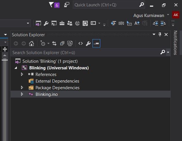
18 2.2.2 Writing Program In this section, we develop program to access Raspberry Pi GPIO using Visual Studio Creating a Project Firstly, we create a project. Open Visual Studio Then, you can create a new project. Select Visual C++-> Windows > Windows IoT Core. Choose Arduino Wiring Application for Windows IoT Core template. Fill LedBlinking on project name. If done, click OK button.

19 If you don t see this template, you can download and install it on a88ac4b01dec. Then, you can see Sketch program on Visual Studio 2015 code editor.
20
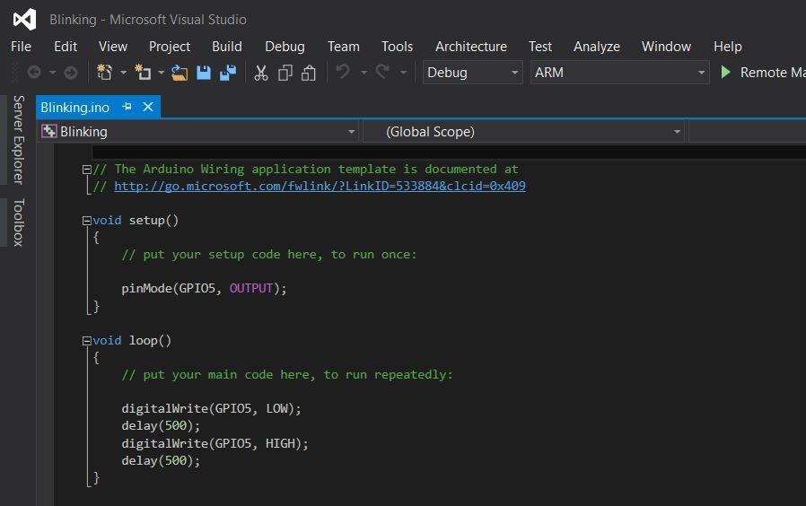
21 Writing Codes Now we can modify our code on Blinking.ino file. Please open that file and write this code. void setup() { pinmode(gpio13, OUTPUT); pinmode(gpio6, OUTPUT); pinmode(gpio5, OUTPUT); } void loop() { digitalwrite(gpio13, HIGH); digitalwrite(gpio6, LOW); digitalwrite(gpio5, LOW); delay(500); digitalwrite(gpio13, LOW); digitalwrite(gpio6, HIGH); digitalwrite(gpio5, LOW); delay(500); digitalwrite(gpio13, LOW); digitalwrite(gpio6, LOW); digitalwrite(gpio5, HIGH); delay(500); } Save this code Configuring Remote Machine You should change target is ARM and Remote Machine.

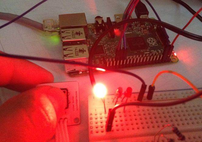
22 Then, open project properties. Select Debugging. Fill Raspberry Pi 2 hostname, such as minwinpc. Then, select Universal (Unencrypted Protocol) on Authentication Type. Save the configuration. Now you compile the program. Make sure you don t get any error on compiling Testing If your program doesn t get errors on compiling, then you can run this program. Click Remote Machine on Debug menu, see the Figure below.


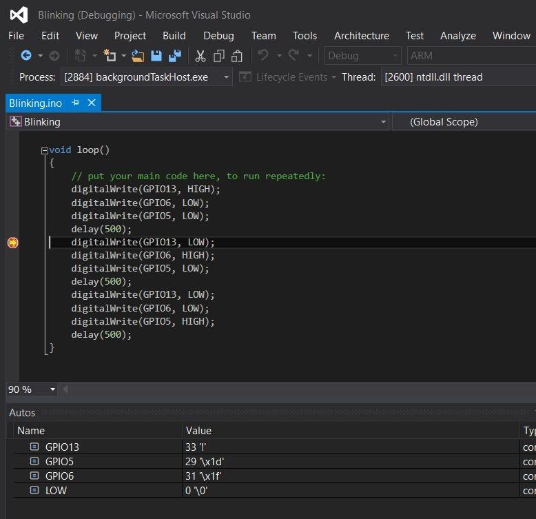
23 If success, you should see LEDs are blinking Debugging We can debug our program. Just set breakpoints on your code.

24 After that, you can run debug by click menu Debug. The debugger will stop on your breakpoints.
25

26 2.3 Demo 2: LED and Pushbutton We build a simple demo to illustrate I/O on Raspberry Pi GPIO. W need a pushbutton and LED. If you press pushbutton, LED will lighting. Otherwise, it will off Wiring Connect your LED into GPIO 13 and pushbutton on GPIO 6. The following is our wiring Writing Program Create a project, call PushLed, on Visual Studio Please follow instructions on section Write this code for PushLed.ino. void setup() { pinmode(gpio13, OUTPUT); pinmode(gpio6, INPUT); }

27 void loop() { int state = digitalread(gpio6); digitalwrite(gpio13, state); delay(500); } Configuring Remote Raspberry Pi We must configure our remote Raspberry Pi and project. Please follow instructions on section Testing Now you can deploy and execute program into Windows 10 IoT Core on Raspberry Pi 2 board. Press pushbutton to get a response from the program. After pressed, you should see the lighting LED.
28
29 3. Serial Communication In this chapter we implement serial port on Raspberry Pi using Arduino Wiring.
30 3.1 Serial Port on Windows 10 IoT Core Microsoft remove Serial object so we can t use Serial in our program now. Please check it on US/win10/ArduinoWiringPortingGuide.htm#port_serial. To send data to the program output, Microsoft provide Log(). We can see the message on Output window of Visual Studio 2015.
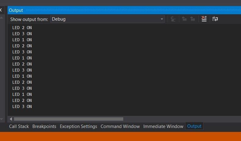
31 3.2 Demo Serial Communication For demo, I use a program from section 2.2. We add messages using Log() so we can monitor these message on Output window. Create Arduino Wiring project, called SerialDemo. See section Then, write this code on SerialDemo.ino. void setup() { pinmode(gpio13, OUTPUT); pinmode(gpio6, OUTPUT); pinmode(gpio5, OUTPUT); } void loop() { Log(L"LED 1 ON \n"); digitalwrite(gpio13, HIGH); digitalwrite(gpio6, LOW); digitalwrite(gpio5, LOW); delay(500); Log(L"LED 2 ON \n"); digitalwrite(gpio13, LOW); digitalwrite(gpio6, HIGH); digitalwrite(gpio5, LOW); delay(500); Log(L"LED 3 ON \n"); digitalwrite(gpio13, LOW); digitalwrite(gpio6, LOW); digitalwrite(gpio5, HIGH); delay(500); } Configure your project to Remote machine for Raspberry Pi. See section After running, you can see message on Output window from Visual Studio.
32
33 4. Analog I/O This chapter explains how to work with Analog I/O in Raspberry Pi 2.
34 4.1 Getting Started Unfortunately, Raspberry Pi 2 doesn t have analog I/O so technically we can t use analogread() and analogwrite() in our program. Alternatively, we can access Analog sensors via SPI and I2C. You can also use ICs such as MCP3008, which support for converting from analog to SPI or I2C. A sample of sensor module-based I2C can be read on chapter 5.
35 5. Working with I2C/TWI Protocol This chapter explains how to work with I2C on Raspberry Pi 2 board and write program to access I2C.
36 5.1 Getting Started The I2C (Inter-Integrated Circuit) bus was designed by Philips in the early 80s to allow easy communication between components which reside on the same circuit board. TWI stands for Two Wire Interface and for most marts this bus is identical to I²C. The name TWI was introduced by Atmel and other companies to avoid conflicts with trademark issues related to I²C. I2C bus consists of two wires, SDA (Serial Data Line) and SCL (Serial Clock Line). The following is I2C bus on Raspberry Pi 2 board. To connect device via I2C, you can do the following connection.
37 You should define which to be master and slave. We also can define 1 master and two slave devices. There are many devices which use I2C to communicate to other. The following is a list of sample device with I2C enabled: EEPROM IC with I2C support ADC/DAC with I2C support, for instance, Real Time Clock (RTC), LCD+Keypad module with I2C support, for instance, For testing, I used PCF8591 AD/DA Converter module with sensor and actuator devices. You can find it on the following online store: Amazon, Conversion/dp/B00BXX4UWC/ ebay, Dealextreme, Aliexpress, In addition, you can find this device on your local electronics store/online store.


38 This module has mini form model too, for instance, you can find it on Amazon, Development/dp/B00KM6X2OI/. This module use PCF8591 IC and you can read the datasheet on the following URLs. On Windows 10 IoT Core for Raspberry Pi 2, we can access I2C via Arduino Wiring
39 program.

40 5.2 Demo: Sensor Device Based I2C The objective of this section is to illustrate how to read data on I2C bus. We use PCF8591 AD/DA converter with sensor devices as I2C external source. You can read this module on this link, In our scenario, we will read three sensor devices in PCF8591 AD/DA modules via I2C. Let s start! Sensor Device Base I2C Now you can connect your PCF8591 AD/DA to Raspberry Pi 2 board. The following is demo wiring : Module SCL > Raspberry Pi 2 board SCL Module SDA > Raspberry Pi 2 board SDA Module VCC > Raspberry Pi 2 board +3.3V Module GND > Raspberry Pi 2 board GND The following is a sample of hardware implementation Writing Program
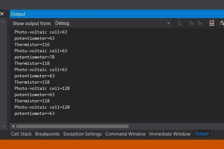
41 In this section, we build a program to access sensor via I2C port Creating a Project Create a new project on Visual Studio 2015, called SensorI2cDemo. Follow the instructions on section Writing Codes Now we modify our code on SensorI2CDemo.ino file. Please open that file and write this code. #include <Wire.h> #define PCF8591 (0x90 >> 1) // I2C bus address #define PCF8591_ADC_CH0 0x00 // thermistor #define PCF8591_ADC_CH1 0x01 // photo-voltaic cell #define PCF8591_ADC_CH2 0x02 #define PCF8591_ADC_CH3 0x03 // potentiometer ULONG ADC1, ADC2, ADC3; void setup() { // put your setup code here, to run once: Wire.begin(); } void loop() { // read thermistor Wire.beginTransmission(PCF8591); Wire.write((byte)PCF8591_ADC_CH0); Wire.endTransmission(); delay(500); Wire.requestFrom(PCF8591, 2); ADC1 = Wire.read(); ADC1 = Wire.read(); Log(L"Thermistor=%d \n", ADC1); // read photo-voltaic cell Wire.beginTransmission(PCF8591); Wire.write(PCF8591_ADC_CH1); Wire.endTransmission(); delay(500); Wire.requestFrom(PCF8591, 2);
42 ADC2 = Wire.read(); ADC2 = Wire.read(); Log(L"Photo-voltaic cell=%d \n", ADC2); // potentiometer Wire.beginTransmission(PCF8591); Wire.write(PCF8591_ADC_CH3); Wire.endTransmission(); delay(500); Wire.requestFrom(PCF8591, 2); ADC3 = Wire.read(); ADC3 = Wire.read(); Log(L"potentiometer=%d \n", ADC3); } delay(1000); You can see that we obtain sensor data from the second byte from sensor device. Save this code Configuring Remote Machine Please configure your remote machine and project based on instruction from section Testing Now you can compile and upload the program to the board in debugging mode. The following is a sample output on debug output
43
44 6. Working with SPI Protocol This chapter explains how to work SPI on Raspberry Pi 2 board and how to access SPI using Arduino Wiring.
45 6.1 Getting Started The Serial Peripheral Interface (SPI) is a communication bus that is used to interface one or more slave peripheral integrated circuits (ICs) to a single master SPI device; usually a microcontroller or microprocessor of some sort. Raspberry Pi 2 has two SPI ports. SPI in Raspberry can be defined on the following pins: SPI0: SPI1: MOSI (GPIO 19) MISO (GPIO 21) SCLK (GPIO 23) CS0 (GPIO 24) CS1 (GPIO 26) MOSI (GPIO 38) MISO (GPIO 35) SCLK (GPIO 40) CS0 (GPIO 11) You can see these pins on the Raspberry Pi GPIO pins, shown in Figure below.

46 Raspberry Pi works as SPI Master. If you want to connect to SPI Slave Devices, you can connect with the following configuration. (image source:
47

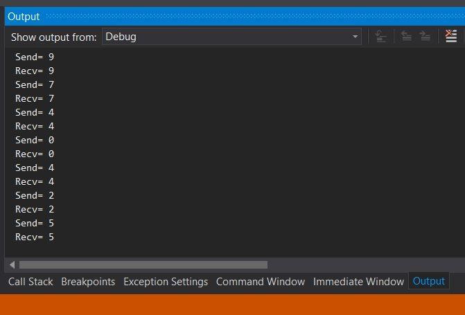
48 6.2 Demo: Hello SPI The objective of the demo is to get started how to work with SPI on Raspberry Pi 2 board using Arduino Wiring. In this scenario, we apply SPI loopback. The following is our scenario: Send one byte data to SPI0 Receive one byte from SPI0 Because we build SPI loopback, we will receive what we sent. Let s start Hardware Configuration Hardware configuration is easy. You just connect MOSI and MISO pins with each other. In this demo, I used SPI0 on Raspberry Pi 2 board so I connect MOSI (GPIO 19) pin to MISO (GPIO 21) pin through a jumper cable. The following is a sample of hardware configuration.
49 6.2.2 Writing Program Create a new project using Visual Studio 2015, called SPILoopback. Please read section Then, modify *.ino file with the following code. #include <SPI.h> ULONG senddata, recvdata; // source: // ULONG randomdigit() { unsigned long t = micros(); byte r = (t % 10) + 1; for (byte i = 1; i <= 4; i++) { t /= 10; r *= ((t % 10) + 1); r %= 11; } return (r - 1); } void setup() { SPI.begin(); } void loop() { senddata = randomdigit(); recvdata = SPI.transfer(sendData); } Log(L"Send= %d \n", senddata); Log(L"Recv= %d \n", recvdata); delay(800); Save this code. Try to configure your project and remote machine based on section Testing Compile and upload your program to remote Raspberry Pi 2 board. You should see sent and received data on Output console. A sample output can be seen in Figure below.
50
51 Source Code Source code can be downloaded on
52 Contact If you have question related to this book, please contact me at My blog:
Embedded Workshop 10/28/15 Rusty Cain
 2 IC Embedded Workshop 10/28/15 Rusty Cain Set up for Workshop: Please Sign in on Sheet. Please include your email. While you are waiting for the Workshop to begin 1. Make sure you are connected to the
Raspberry Pi. Hans-Petter Halvorsen, M.Sc.
 Raspberry Pi Hans-Petter Halvorsen, M.Sc. Raspberry Pi https://www.raspberrypi.org https://dev.windows.com/iot Hans-Petter Halvorsen, M.Sc. Raspberry Pi - Overview The Raspberry Pi 2 is a low cost, credit-card
Microcontrollers and Interfacing
 Microcontrollers and Interfacing Week 10 Serial communication with devices: Serial Peripheral Interconnect (SPI) and Inter-Integrated Circuit (I 2 C) protocols College of Information Science and Engineering
ARDUINO YÚN MINI Code: A000108
 ARDUINO YÚN MINI Code: A000108 The Arduino Yún Mini is a compact version of the Arduino YUN OVERVIEW: Arduino Yún Mini is a breadboard PCB developed with ATmega 32u4 MCU and QCA MIPS 24K SoC CPU operating
1.6inch SPI Module user manual
 1.6inch SPI Module user manual www.lcdwiki.com 1 / 10 Rev1.0 Product Description The 1.6 module is tested using the ESP8266MOD D1 Mini development board, Both the test program and the dependent libraries
ARDUINO YÚN Code: A000008
 ARDUINO YÚN Code: A000008 Arduino YÚN is the perfect board to use when designing connected devices and, more in general, Internet of Things projects. It combines the power of Linux with the ease of use
keyestudio Keyestudio MEGA 2560 R3 Board
 Keyestudio MEGA 2560 R3 Board Introduction: Keyestudio Mega 2560 R3 is a microcontroller board based on the ATMEGA2560-16AU, fully compatible with ARDUINO MEGA 2560 REV3. It has 54 digital input/output
I2C interface Tutorial
 UG108: Praxis II January 2013 Asian Institute of Technology Undergraduate Program Handout: I2C interface Instructor: Chaiyaporn Silawatchananai, Matthew N. Dailey I2C interface Tutorial Introduction: In
Digital Circuits Part 2 - Communication
 Introductory Medical Device Prototyping Digital Circuits Part 2 - Communication, http://saliterman.umn.edu/ Department of Biomedical Engineering, University of Minnesota Topics Microcontrollers Memory
ARDUINO PRIMO. Code: A000135
 ARDUINO PRIMO Code: A000135 Primo combines the processing power from the Nordic nrf52 processor, an Espressif ESP8266 for WiFi, as well as several onboard sensors and a battery charger. The nrf52 includes
ADC to I 2 C. Data Sheet. 10 Channel Analog to Digital Converter. with output via I 2 C
 Data Sheet 10 Channel Analog to Digital Converter with output via I 2 C Introduction Many microcontroller projects involve the use of sensors like Accelerometers, Gyroscopes, Temperature, Compass, Barometric,
ARDUINO INDUSTRIAL 1 01 Code: A000126
 ARDUINO INDUSTRIAL 1 01 Code: A000126 The Industrial 101 is a small form-factor YUN designed for product integration. OVERVIEW: Arduino Industrial 101 is an Evaluation board for Arduino 101 LGA module.
Arduino Prof. Dr. Magdy M. Abdelhameed
 Course Code: MDP 454, Course Name:, Second Semester 2014 Arduino What is Arduino? Microcontroller Platform Okay but what s a Microcontroller? Tiny, self-contained computers in an IC Often contain peripherals
LinkSprite Technologies,.Inc. pcduino V2
 1 2 Contents Board Overview...3 System Features...4 Single-Board Computer Configuration...5 Pin Assignments...7 Single-Board Computer Setup...9 Required Hardware...9 Optional Hardware...9 Adjusting Screen
Getting Started Guide XC9010 Raspberry Pi Starter Kit
 Getting Started Guide XC9010 Raspberry Pi Starter Kit The Raspberry Pi has been designed as a computer that anyone can use. If you want to get started with a Raspberry Pi, but don t know where to start,
How to Use an Arduino
 How to Use an Arduino By Vivian Law Introduction The first microcontroller, TMS-1802-NC, was built in 1971 by Texas Instruments. It owed its existence to the innovation and versatility of silicon and the
ArduCAM-M-2MP ESP8266 Evaluation Kit User Guide. Rev 1.1, March 2017
 ArduCAM-M-2MP ESP8266 Evaluation Kit User Guide Rev 1.1, March 2017 Table of Contents 1 Introduction... 2 2 Kit Content... 2 3 Features... 2 4 Pin Definition... 3 5 Wiring Diagram... 4 6 Getting Started
Parallel Data Transfer. Suppose you need to transfer data from one HCS12 to another. How can you do this?
 Introduction the Serial Communications Huang Sections 9.2, 10.2, 11.2 SCI Block User Guide SPI Block User Guide IIC Block User Guide o Parallel vs Serial Communication o Synchronous and Asynchronous Serial
pcduino V3B XC4350 User Manual
 pcduino V3B XC4350 User Manual 1 User Manual Contents Board Overview...2 System Features...3 Single-Board Computer Configuration......3 Pin Assignments...4 Single-Board Computer Setup...6 Required Hardware...6
ARDUINO LEONARDO ETH Code: A000022
 ARDUINO LEONARDO ETH Code: A000022 All the fun of a Leonardo, plus an Ethernet port to extend your project to the IoT world. You can control sensors and actuators via the internet as a client or server.
Introduction to Microcontrollers
 Introduction to Microcontrollers June 2017 Scott A. Theis W2LW Rev 5 ( 0 8 / 0 2 / 2 0 1 7 ) What s it all about How to get started What are some of the common controller options General introduction to
Nano RK And Zigduino. wnfa ta course hikaru4
 Nano RK And Zigduino wnfa ta course hikaru4 Today's outline Zigduino v.s. Firefly Atmel processor and the program chip I/O Interface on the board Atmega128rfa1, FTDI chip... GPIO, ADC, UART, SPI, I2C...
Introduction the Serial Communications Parallel Communications Parallel Communications with Handshaking Serial Communications
 Introduction the Serial Communications Parallel Communications Parallel Communications with Handshaking Serial Communications o Asynchronous Serial (SCI, RS-232) o Synchronous Serial (SPI, IIC) The MC9S12
Prototyping Module Datasheet
 Prototyping Module Datasheet Part Numbers: MPROTO100 rev 002 Zenseio LLC Updated: September 2016 Table of Contents Table of Contents Functional description PROTOTYPING MODULE OVERVIEW FEATURES BLOCK DIAGRAM
Arduino Uno R3 INTRODUCTION
 Arduino Uno R3 INTRODUCTION Arduino is used for building different types of electronic circuits easily using of both a physical programmable circuit board usually microcontroller and piece of code running
w w w. b a s e t r a i n i n g i n s t i t u t e. c o
 Disclaimer: Some of the images and most of the data in this presentation are collected from various sources in the internet. If you notice any copyright issues or mistakes, please let me know by mailing
ARDUINO BOARD LINE UP
 Technical Specifications Pinout Diagrams Technical Comparison Board Name Processor Operating/Input Voltage CPU Speed Analog In/Out Digital IO/PWM USB UART 101 Intel Curie 3.3 V/ 7-12V 32MHz 6/0 14/4 Regular
Raspberry Pi - I/O Interfaces
 ECE 1160/2160 Embedded Systems Design Raspberry Pi - I/O Interfaces Wei Gao ECE 1160/2160 Embedded Systems Design 1 I/O Interfaces Parallel I/O and Serial I/O Parallel I/O: multiple input/output simultaneously
参考資料. LinkSprite.com. pcduino V2
 pcduino V2 1 Contents Board Overview...3 System Features...4 Single-Board Computer Configuration......5 Pin Assignments...7 Single-Board Computer Setup......9 Required Hardware......9 Optional Hardware......9
Lab 01 Arduino 程式設計實驗. Essential Arduino Programming and Digital Signal Process
 Lab 01 Arduino 程式設計實驗 Essential Arduino Programming and Digital Signal Process Arduino Arduino is an open-source electronics prototyping platform based on flexible, easy-to-use hardware and software. It's
AN10428 UART-SPI Gateway for Philips SPI slave bridges
 UART-SPI Gateway for Philips SPI slave bridges Rev. 01 7 March 2006 Application note Document information Info Keywords Abstract Content UART-SPI Gateway, UART to SPI, RS-232 to SPI The UART-SPI Gateway
ARDUINO LEONARDO WITH HEADERS Code: A000057
 ARDUINO LEONARDO WITH HEADERS Code: A000057 Similar to an Arduino UNO, can be recognized by computer as a mouse or keyboard. The Arduino Leonardo is a microcontroller board based on the ATmega32u4 (datasheet).
Compute Module IO Board Plus User Manual
 Compute Module IO Board Plus User Manual OVERVIEWS This is an Expansion board of Compute Module 3 and Compute Module 3 Lite. It is compatible with Compute Module IO Board V3 from Raspberry Pi Foundation,
Exen Mini. Setup Guide - V1. nerdonic.com
 nerdonic. Exen Mini Setup Guide - V1 01 Exen Mini - Pinout SWCLK SWDIO RESET 3.3V GND POWER LED SWD HEADER PROGRAMMABLE LED 8 / PA06 3.3-20V INPUT REGULATED TO 3.3V 3.3-20V 3.3V INPUT OR REGULATED 3.3V
Cooking with Team 279
 Cooking with Team 279 Intro to the Raspberry Pi FIRST Team 279 Tech Fusion http://team279.com - https://twitter.com/team_279 Author: Michael Lehman What is a System on a Chip? From Wikipedia: A system
Embedded distributed/parallel computing hardware for high school students
 Embedded distributed/parallel computing hardware for high school students Hannes Haljaste Institute of Computer Science University of Tartu gamexh@ut.ee Abstract This paper focuses on embedded distributed/parallel
Microcontrollers and Interfacing week 10 exercises
 1 SERIAL PERIPHERAL INTERFACE (SPI) HARDWARE Microcontrollers and Interfacing week 10 exercises 1 Serial Peripheral Interface (SPI) hardware Complex devices (persistent memory and flash memory cards, D/A
SPI (Serial & Peripheral Interface)
") SPI (Serial & Peripheral Interface) What is SPI SPI is a high-speed, full-duplex bus that uses a minimum of 3 wires to exchange data. The popularity of this bus rose when SD cards (and its variants ie:
SPI (Serial & Peripheral Interface) What is SPI SPI is a high-speed, full-duplex bus that uses a minimum of 3 wires to exchange data. The popularity of this bus rose when SD cards (and its variants ie:
ARDUINO M0 PRO Code: A000111
 ARDUINO M0 PRO Code: A000111 The Arduino M0 Pro is an Arduino M0 with a step by step debugger With the new Arduino M0 Pro board, the more creative individual will have the potential to create one s most
EDJE PROJECT. The Software Foundation for IoT Devices. https://projects.eclipse.org/projects/iot.edje. IS2T S.A All rights reserved.
 EDJE PROJECT The Software Foundation for IoT Devices https://projects.eclipse.org/projects/iot.edje IS2T S.A. 2016. All rights reserved. PRESENTER Jérôme Leroux Development and Innovation Manager at MicroEJ
Design and development of embedded systems for the Internet of Things (IoT) Fabio Angeletti Fabrizio Gattuso
 Fabio Angeletti Fabrizio Gattuso") Design and development of embedded systems for the Internet of Things (IoT) Fabio Angeletti Fabrizio Gattuso Microcontroller It is essentially a small computer on a chip Like any computer, it has memory,
Design and development of embedded systems for the Internet of Things (IoT) Fabio Angeletti Fabrizio Gattuso Microcontroller It is essentially a small computer on a chip Like any computer, it has memory,
Lesson 6 Intel Galileo and Edison Prototype Development Platforms. Chapter-8 L06: "Internet of Things ", Raj Kamal, Publs.: McGraw-Hill Education
 Lesson 6 Intel Galileo and Edison Prototype Development Platforms 1 Intel Galileo Gen 2 Boards Based on the Intel Pentium architecture Includes features of single threaded, single core and 400 MHz constant
ARDUINO MEGA ADK REV3 Code: A000069
 ARDUINO MEGA ADK REV3 Code: A000069 OVERVIEW The Arduino MEGA ADK is a microcontroller board based on the ATmega2560. It has a USB host interface to connect with Android based phones, based on the MAX3421e
ArduCAM-M-5MP Camera Shield
 ArduCAM-M-5MP Camera Shield 5MP SPI Camera User Guide Rev 1.0, Mar 2015 Table of Contents 1 Introduction... 2 2 Application... 2 3 Features... 3 4 Key Specifications... 3 5 Pin Definition... 3 6 Block
USB-to-I2C. Ultra Hardware User s Manual.
 USB-to-I2C Ultra Hardware User s Manual https://www.i2ctools.com/ Information provided in this document is solely for use with the USB-to-I2C Ultra product from SB Solutions, Inc. SB Solutions, Inc. reserves
The industrial technology is rapidly moving towards ARM based solutions. Keeping this in mind, we are providing a Embedded ARM Training Suite.
 EMBEDDED ARM TRAINING SUITE ARM SUITE INCLUDES ARM 7 TRAINER KIT COMPILER AND DEBUGGER THROUGH JTAG INTERFACE PROJECT DEVELOPMENT SOLUTION FOR ARM 7 e-linux LAB FOR ARM 9 TRAINING PROGRAM INTRODUCTION
Sten-SLATE ESP. Accelerometer and I2C Bus
 Sten-SLATE ESP Accelerometer and I2C Bus Stensat Group LLC, Copyright 2016 I2C Bus I2C stands for Inter-Integrated Circuit. It is a serial type interface requiring only two signals, a clock signal and
Arduino ADK Rev.3 Board A000069
 Arduino ADK Rev.3 Board A000069 Overview The Arduino ADK is a microcontroller board based on the ATmega2560 (datasheet). It has a USB host interface to connect with Android based phones, based on the MAX3421e
Sanguino TSB. Introduction: Features:
 Sanguino TSB Introduction: Atmega644 is being used as CNC machine driver for a while. In 2012, Kristian Sloth Lauszus from Denmark developed a hardware add-on of Atmega644 for the popular Arduino IDE and
PARALLEL COMMUNICATIONS
 Parallel Data Transfer Suppose you need to transfer data from one HCS12 to another. How can you do this? You could connect PORTA of the sending computer (set up as an output port) to PORTA of the receiving
Microcontroller basics
 FYS3240 PC-based instrumentation and microcontrollers Microcontroller basics Spring 2017 Lecture #4 Bekkeng, 30.01.2017 Lab: AVR Studio Microcontrollers can be programmed using Assembly or C language In
Embedded Systems and Software. Serial Interconnect Buses I 2 C (SMB) and SPI
 and SPI") Embedded Systems and Software Serial Interconnect Buses I 2 C (SMB) and SPI I2C, SPI, etc. Slide 1 Provide low-cost i.e., low wire/pin count connection between IC devices There are many of serial bus standards
Embedded Systems and Software Serial Interconnect Buses I 2 C (SMB) and SPI I2C, SPI, etc. Slide 1 Provide low-cost i.e., low wire/pin count connection between IC devices There are many of serial bus standards
or between microcontrollers)
") : Communication Interfaces in Embedded Systems (e.g., to interface with sensors and actuators or between microcontrollers) Spring 2016 : Communication Interfaces in Embedded Systems Spring (e.g., 2016
: Communication Interfaces in Embedded Systems (e.g., to interface with sensors and actuators or between microcontrollers) Spring 2016 : Communication Interfaces in Embedded Systems Spring (e.g., 2016
USB-to-I2C. Professional Hardware User s Manual.
 USB-to-I2C Professional Hardware User s Manual https://www.i2ctools.com/ Information provided in this document is solely for use with the USB-to-I2C Professional product from SB Solutions, Inc. SB Solutions,
Win-I2CUSB Hardware User s Manual
 Win-I2CUSB Hardware User s Manual http://www.demoboard.com Information provided in this document is solely for use with the Win-I2CUSB product from The Boardshop. The Boardshop and SB Solutions, Inc. reserve
ARDUINO MICRO WITHOUT HEADERS Code: A000093
 ARDUINO MICRO WITHOUT HEADERS Code: A000093 Arduino Micro is the smallest board of the family, easy to integrate it in everyday objects to make them interactive. The Micro is based on the ATmega32U4 microcontroller
ArduCAM CC3200 UNO board
 ArduCAM CC3200 UNO board User Guide Rev 1.2, Mar 2017 Table of Contents 1 Introduction... 2 2 Features... 3 3 Pin Definition... 4 4 Getting Started CC3200 with Energia... 5 4.1 Out of the Box Test... 5
Laboratory 5 Communication Interfaces
 Laboratory 5 Communication Interfaces Embedded electronics refers to the interconnection of circuits (micro-processors or other integrated circuits) with the goal of creating a unified system. In order
Serial Peripheral Interface. What is it? Basic SPI. Capabilities. Protocol. Pros and Cons. Uses
 Serial Peripheral Interface What is it? Basic SPI Capabilities Protocol Serial Peripheral Interface http://upload.wikimedia.org/wikipedia/commons/thumb/e/ed/ SPI_single_slave.svg/350px-SPI_single_slave.svg.png
Intel Galileo gen 2 Board
 Intel Galileo gen 2 Board The Arduino Intel Galileo board is a microcontroller board based on the Intel Quark SoC X1000, a 32- bit Intel Pentium -class system on a chip (SoC). It is the first board based
Introduction the Serial Communications Huang Sections 9.2, 10.2 SCI Block User Guide SPI Block User Guide
 Introduction the Serial Communications Huang Sections 9.2,.2 SCI Block User Guide SPI Block User Guide Parallel Data Transfer Suppose you need to transfer data from one HCS2 to another. How can you do
3.3V regulator. JA H-bridge. Doc: page 1 of 7
 Digilent Cerebot Board Reference Manual Revision: 11/17/2005 www.digilentinc.com 215 E Main Suite D Pullman, WA 99163 (509) 334 6306 Voice and Fax Overview The Digilent Cerebot Board is a useful tool for
KNJN I2C bus development boards
 KNJN I2C bus development boards 2005, 2006, 2007, 2008 fpga4fun.com & KNJN LLC http://www.knjn.com/ Document last revision on January 1, 2008 R12 KNJN I2C bus development boards Page 1 Table of Contents
Ultratronics v1.0 DATASHEET
 Ultratronics v1.0 DATASHEET Author Bart Meijer Date November 21 st, 2017 Document version 1.2 Ultratronics Datasheet Reprapworld.com 1 PRODUCT OVERVIEW Ultratronics is the latest development in 3D printer
Part Number: PCB-STM32-F4B1 (unpopulated PCB with Discovery module sockets, no other parts) STM32-F4B1 (assembled board, not presently available)
 STM32-F4B1 (assembled board, not presently available)") PCB-STM32-F4B1 Development baseboard for the STMicro Discovery-F4 module (STMicro part# STM32F4DISCOVERY) PCB Rev 1.00 shown. PCB Rev 1.20 has on-board RS232 drivers. Part Number: PCB-STM32-F4B1 (unpopulated
PCB-STM32-F4B1 Development baseboard for the STMicro Discovery-F4 module (STMicro part# STM32F4DISCOVERY) PCB Rev 1.00 shown. PCB Rev 1.20 has on-board RS232 drivers. Part Number: PCB-STM32-F4B1 (unpopulated
USER GUIDE EDBG. Description
 USER GUIDE EDBG Description The Atmel Embedded Debugger (EDBG) is an onboard debugger for integration into development kits with Atmel MCUs. In addition to programming and debugging support through Atmel
ESPino - Specifications
 ESPino - Specifications Summary Microcontroller ESP8266 (32-bit RISC) WiFi 802.11 (station, access point, P2P) Operating Voltage 3.3V Input Voltage 4.4-15V Digital I/O Pins 9 Analog Input Pins 1 (10-bit
Overview of the Raspberry Pi Models 3B & 2B
 Overview of the Raspberry Pi Models 3B & 2B (Let's look at the hardware!) Rick Commo, K7LOG Max Vaughan, KF7MAX What's really different between the original 2B and the 3B? Parameter Architecture CPU
Arduino Uno. Arduino Uno R3 Front. Arduino Uno R2 Front
 Arduino Uno Arduino Uno R3 Front Arduino Uno R2 Front Arduino Uno SMD Arduino Uno R3 Back Arduino Uno Front Arduino Uno Back Overview The Arduino Uno is a microcontroller board based on the ATmega328 (datasheet).
Raspberry Pi Expansion Module User Manual
 Raspberry Pi Expansion Module User Manual 52PI-RPI-AD/DA Maximum Power at Minimum Size Raspberry Pi AD/DA Expansion Module User Manual - 1 - Contact Us Raspberry Pi Geek Forum admin@52pi.net Version:1.0
MicroBolt. Microcomputer/Controller Featuring the Philips LPC2106 FEATURES
 Microcomputer/Controller Featuring the Philips LPC2106 FEATURES Powerful 60 MHz, 32-bit ARM processing core. Pin compatible with 24 pin Stamp-like controllers. Small size complete computer/controller with
Bus & Signal Processing
 Prototyping Electronic Devices Class 12 Bus & Signal Processing Deqing Sun, Peiqi Su ITP, Fall, 2018 What is bus 2 Differences between Bus and Cab? 3 Differences between Bus and Cab Bus is capable to carry
The Digital Revolution
 Raspberry Pi A Learning Experience (For me!) Charlie Rothrock K3SR The Digital Revolution Geewhiz Statistics -Digital is changing the world -Tech companies are ~10+% of US employment and the fastest wage
A Low Cost Internet of Things Network for Contamination Detection in Drinking Water Systems Using Raspberry Pi
 A Low Cost Internet of Things Network for Contamination Detection in Drinking Water Systems Using Raspberry Pi Syeda Madeeha Anam 1, M Devender 2 1 M.Tech Scholar, Sudheer Reddy College of Engineering
High-Precision AD/DA Board User Manual
 High-Precision AD/DA Board User Manual Overview There's no AD/DA function on the Raspberry Pi GPIO interface, this may troubled you in the Pi development. However, it won't be a problem anymore. The High-Precision
Low-Cost Microcontrollers
 Low-Cost Microcontrollers Examples and Applications for Embedded Systems João Carlos Martins joao.martins@ipbeja.pt Engineering Dept 1st Workshop on Applied Signal Processing IPBeja 15th May 2014 Outline
Universität Dortmund. IO and Peripheral Interfaces
 IO and Peripheral Interfaces Microcontroller System Architecture Each MCU (micro-controller unit) is characterized by: Microprocessor 8,16,32 bit architecture Usually simple in-order microarchitecture,
Doc: page 1 of 6
 Nanocon Reference Manual Revision: February 9, 2009 Note: This document applies to REV A-B of the board. 215 E Main Suite D Pullman, WA 99163 (509) 334 6306 Voice and Fax Overview The Nanocon board is
KNJN I2C bus development boards
 KNJN I2C bus development boards 2005, 2006, 2007, 2008 KNJN LLC http://www.knjn.com/ Document last revision on December 5, 2008 R22 KNJN I2C bus development boards Page 1 Table of Contents 1 The I2C bus...4
ARDUINO UNO REV3 Code: A000066
 ARDUINO UNO REV3 Code: A000066 The UNO is the best board to get started with electronics and coding. If this is your first experience tinkering with the platform, the UNO is the most robust board you can
Alessandra de Vitis. Arduino
 Alessandra de Vitis Arduino Arduino types Alessandra de Vitis 2 Interfacing Interfacing represents the link between devices that operate with different physical quantities. Interface board or simply or
Distributed Real- Time Control Systems
 Distributed Real- Time Control Systems Lecture 2 Embedded Systems Basics A. Bernardino, C. Silvestre, IST- ACSDC 1 What are embedded systems? Small computers to efficiently address specific purposes, e.g.
Arduino Programming. Arduino UNO & Innoesys Educational Shield
 Arduino Programming Arduino UNO & Innoesys Educational Shield www.devobox.com Electronic Components & Prototyping Tools 79 Leandrou, 10443, Athens +30 210 51 55 513, info@devobox.com ARDUINO UNO... 3 INNOESYS
HZX N03 Bluetooth 4.0 Low Energy Module Datasheet
 HZX-51822-16N03 Bluetooth 4.0 Low Energy Module Datasheet SHEN ZHEN HUAZHIXIN TECHNOLOGY LTD 2017.7 NAME : Bluetooth 4.0 Low Energy Module MODEL NO. : HZX-51822-16N03 VERSION : V1.0 1.Revision History
Introduction to Arduino
 Introduction to Arduino Paco Abad May 20 th, 2011 WGM #21 Outline What is Arduino? Where to start Types Shields Alternatives Know your board Installing and using the IDE Digital output Serial communication
COOKING WITH TEAM 279
 COOKING WITH TEAM 279 ANALOG SIGNALS WITH MCP3002/MCP3008 ADC The RPi does not have analog input pins. To read analog signals, and Analog to Digital Converter (ADC) should be used. The MCP3002 and MCP3008
Exen Mini. Setup Guide - V2. nerdonic.com
 nerdonic. Exen Mini Setup Guide - V2 01 Setup Guide - Changelog V2 - Added common PC connection and Unknown Device fixes 02 SWCLK SWDIO RESET 3.3V GND Exen Mini - Pinout POWER LED SWD HEADER PROGRAMMABLE
Hands on Experience with AVR32
 Hands on Experience with AVR32 By: Mazhar Hussain mazhar.hussain @miun.se Muhammad Amir Yousaf 1 Tutorial Overview Introduction to AT32UC3A0512 (µ-controller) µ-controller Sensors Display Peripherals AVR
Distributed Real- Time Control Systems
 Distributed Real- Time Control Systems Lecture 4 Embedded Systems Communica:ons A. Bernardino, C. Silvestre, IST- ACSDC 1 Interfaces I/O Digital I/O Analog Input PWM Serial SPI TWI A. Bernardino, C. Silvestre,
ECE471: Embedded Systems Homework 7 SPI, A/D and Temperature Probe. Due: Friday, 2 November 2018, 10:00am
 ECE471: Embedded Systems Homework 7 SPI, A/D and Temperature Probe Due: Friday, 2 November 2018, 10:00am 1. You may work in groups of two on this homework. You will need an MCP3008 SPI A/D converter as
Electronics Single Board Computers
 Electronics Single Board Computers Wilfrid Laurier University November 23, 2016 Single Board Computers Single Board Computers As electronic devices get smaller and more sophisticated, they often contain
Various power connectors. 3.3V regulator. 64K Flash (Internal) 2K EEPROM (Internal) 4K SRAM (Internal) JA Mem Adr/ Data. Doc: page 1 of 9
 2K EEPROM (Internal) 4K SRAM (Internal) JA Mem Adr/ Data. Doc: page 1 of 9") Cerebot II Board Reference Manual Revision: September 14, 2007 Note: This document applies to REV B of the board. www.digilentinc.com 215 E Main Suite D Pullman, WA 99163 (509) 334 6306 Voice and Fax Overview
Cerebot II Board Reference Manual Revision: September 14, 2007 Note: This document applies to REV B of the board. www.digilentinc.com 215 E Main Suite D Pullman, WA 99163 (509) 334 6306 Voice and Fax Overview
Lecture 25 March 23, 2012 Introduction to Serial Communications
 Lecture 25 March 23, 2012 Introduction to Serial Communications Parallel Communications Parallel Communications with Handshaking Serial Communications Asynchronous Serial (e.g., SCI, RS-232) Synchronous
EasyPIC5 Development System
 EasyPIC5 Development System Part No.: MPMICRO-PIC-Devel- EasyPIC5 Overview EasyPIC5 is a development system that supports over 120 8-, 14-, 18-, 20-, 28- and 40-pin PIC MCUs. EasyPIC5 allows PIC microcontrollers
LIS3DH Hookup Guide. Introduction. SparkFun Triple Axis Accelerometer Breakout - LIS3DH SEN Required Materials
 Page 1 of 15 LIS3DH Hookup Guide Introduction The LIS3DH is a triple axis accelerometer you can use to add translation detection to your project. It would be classified as a 3DoF, or 3 Degrees of Freedom.
User's Manual Rev. 1. Freescale Semiconductor Inc. TWRS08UNIVUM
 TWR-S08UNIV User's Manual Rev. 1 Freescale Semiconductor Inc. TWRS08UNIVUM Table of Contents 1. TWR-S08UNIV and TWR-S08DC Overview... 4 1.1 Contents... 5 1.2 Features... 5 2. Getting Started... 7 2.1 Reference
XNUCLEO-F030R8, Improved STM32 NUCLEO Board
 XNUCLEO-F030R8, Improved STM32 NUCLEO Board STM32 Development Board, Supports Arduino, Compatible with NUCLEO-F030R8 XNUCLEO-F030R8 Features Compatible with NUCLEO-F030R8, onboard Cortex-M0 microcontroller
Raspberry Pi board. EB080
 Raspberry Pi board www.matrixmultimedia.com EB080 Contents About this document 3 Board layout 3 General information 4 Circuit description 4 Circuit diagram 5 2 Copyright Matrix Multimedia Ltd. About this
Getting to know the Arduino IDE
 Getting to know the Arduino IDE I ve heard about Arduino, what the heck is it? Arduino is a development environment Combination of hardware and software Hardware based on Atmel AVR processors Software
Wireless Sensor Networks. FireFly 2.2 Datasheet
 2.2 Datasheet July 6, 2010 This page intentionally left blank. Contents 1. INTRODUCTION...1 Features...1 Applications...2 2. BLOCK DIAGRAM...3 3. HARDWARE CONNECTIONS...4 Power...5 Header 1 ( UARTS, I2C,