DESCRIPTION OF DIGIBUS CONTROLLER SWITCHBOARD PROGRAM (Art.94CD)
|
|
|
- Shawn Albert Stanley
- 5 years ago
- Views:
Transcription
1 GENERAL DESCRIPTION: DESCRIPTION OF DIGIBUS CONTROLLER SWITCHBOARD PROGRAM (Art.94CD) DIGIBUS CONTROLLER software allows a PC (equipped with a suitable interface) to be used as a switchboard for ELVOX Digibus System installations. With this system connected in a Digibus installation all the main operations available with a normal switchboard are possible, plus a series of functions optimised thanks to the processing capabilities of the PC. The main functions available using the switchboard program are: 1) Direct and conference call to any number from the keypad in the centre of the screen. 2) Facility to create a database of users (telephone directory) with number, name, surname, building and other personal data. Facility to call any user direct from database. 3) Facility for database sorting and searching (by surname, number, building). 4) When a number is dialed on the keypad, the display simultaneously shows the name of the corresponding person. When a call is received it is simultaneously linked to the corresponding name from the database. 5) Facility to record each operation (call, activation, etc.) executed from and towards the switchboard. The data are displayed in a dedicated window and simultaneously saved to files (daily or monthly) that can be stored and analysed at any time. 6) Storage of calls and service requests in a dedicated buffer memory. Audible/optical alerts active until all calls have been processed. 7) Possibility of activating locks and auxiliary functions (F1, F2) on the entire installation. 8) Facility to test each connected interphone (without disturbing the user) and check that it is functioning correctly. 9) Facility to save an interactive map of the installation. Facility to access and call users in all buildings directly from the map in graphic mode using exclusively the mouse. Used also to retrieve descriptive text concerning each building on the map. 10) System completely configurable, including ringing tones, record modes, and items to be recorded. Facility to program operating modes of pending calls memory (i.e. calls to be served by calling back the user or cancelling individual calls). 1

2 STARTING SCREEN: ON LINE HELP: 2
3 The Digibus Controller program features 2 simple help modes, which can be used at any time: 1) Screen tips for each button: mousing over (~1 sec) each button (or active object) on the screen causes a short descriptive text of the functions associated with the object to be displayed. 2) All the main pages have a HELP button : When pressed, a box appears on the screen with a brief description of the purpose of the page and all the main objects on it (N.B.: for long descriptions move the cursor to the right to view the part that is not visible). To hide the descriptive text box press the HELP button again. EXIT BUTTON: To close the program always use this button (in this way all the files and the serial channel are closed correctly). BACK BUTTON: The back button appears when a submenu is accessed. Pressing the back button restores the previous page. PRELIMINARY OPERATIONS (AND CONFIGURATIONS): The following steps must be carried out before operating the switchboard: - 1 ) SOFTWARE INSTALLATION: see appendix A - 2) SPECIAL INTERFACE CONNECTION: see appendix B. NB: if the interface is not connected the software operates normally but calls have no effect on the system. - 3) CREATION OF THE USERS DATABASE: For the system to reach its full potential, data of users to be called from the switchboard must be entered in the database. This can be done later (and also gradually); however, until the relevant user information has been entered the corresponding users cannot be called directly from the telephone directory and the corresponding names cannot be recognised by the software when a call is received. The main data to insert are the interphone number (i.e. the Digibus number assigned to the interphone), surname, name and building number (to allow selections of users located in a specific building). The additional data, although not strictly necessary, are used for special information and future implementations. For data entry methods see the TELEPHONIC LIST section. - 4) CREATION OF THE SYSTEM MAP: (optional). From the switchboard it is possible to view the system map, identify the position of the buildings, retrieve the relative descriptive text and select (and call) the users in the building selected using the mouse. To create the map the appropriate procedure must be carried out (see SYSTEM MAP section) whereby all the graphic objects on the screen are defined together with the building mnemonic data. 3
: The following parameters must be configured from this screen: - SYSTEM DIGIT")
4 - 5) SETUP MENU: several basic parameters for the operation of the program must be configured in the setup menu. To do this press the SETUP button at the bottom right of the screen to display the following screen (CONFIGURATION PANEL): The following parameters must be configured from this screen: - SYSTEM DIGIT N (top left): Select 4 or 8 digits depending on the type of system. Use on 8 digit systems is recommended since with 4 digits (older systems) several functions will not be available. - N COM PC: this is the serial port to which the serial interface is connected (take care to avoid conflict on the PC with other peripheral devices). - CONVERSATION TIME: maximum duration of conversation from system (in seconds). After this interval the communication is interrupted, freeing communications on the engaged entrance panels. 4
5 - N OF CALL REPEATS (N Call Repeat): Number of repeats of an alert sound signal after receipt of a call. The sound will be repeated at regular intervals according to the setting in the Time Repetition box. - SOUND FILE ASSOCIATION: To select sound files (.wav extension) to associate with specific events. These are: MEMO CALL: sound played when each call is received (or other command that you wish to record in the pending calls memory). REPEAT MEMO: sound that will be repeated after a call for the set number of times and at the set interval. This is the sound that reminds the operator that the call is pending CALL FROM SWITCH: sound played each time a call is made from the switchboard PRESS KEYBOARD: optional keypad tone associated with each key press (must be very brief to avoid slowing keyboard acquisition rate) - DIGIBUS NUMBER KEYBOARD SWITCH: Digibus number associated with the switchboard (to identify switchboard unequivocally). - PREFIX NUMBER FOR ENTRANCE PANELS: prefix number (first 2 digits) set on the entrance panels. This number is used only to discriminate between calls from an entrance panel or from an interphone. If you press Set Preferential Number button to display the following screen: In this screen is possible select seven numbers of 7 preferential entrance panels on which you wish to activate the lock in rapid mode (or additional functions F1 and F2). Another seven numbers of 7 auxiliary digital device permit activation (with F3, F6, F7 function) of load not localized near entrance panels (with ART. 170/D). 5
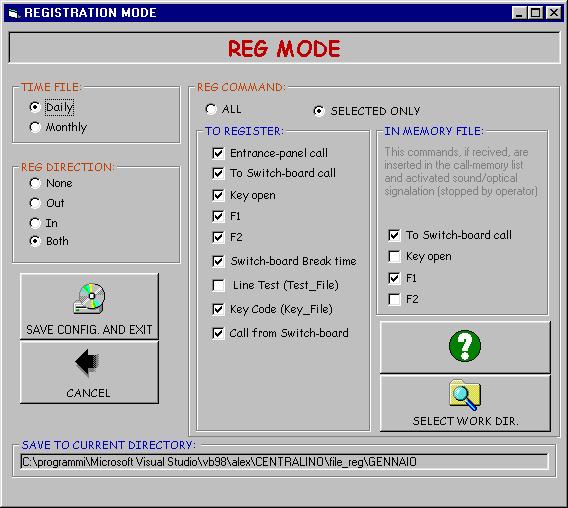
6 To activate all these functions simply press the buttons at the left of the main switchboard screen. For the methods of use see section ACTIVATION OF LOCKS OR FUNCTION KEYS FROM THE SWITCHBOARD. - 6) SETTING RECORDING MODES: When the SET REG button on the bottom right is pressed, the following menu (REG MODE) appears, wherein you can define everything you wish to record, both in a permanent file (on the hard disk) and in the switchboard's Pending Calls Memory. This menu allows you to decide what to record to file (for storage and subsequent review at a later date) and what to record in the Pending Calls Memory. It is useful to remember the difference between these two memories: PENDING CALLS MEMORY: several specific commands (Call from User to Switchboard, F1, F2, Key) can, if so desired, trigger an audible/optical signal when received; the signal persists until the switchboard operator calls back the internal number that made the call. In this case, these commands are displayed in a specific memory that can be displayed on the PENDING CALLS MEMORY page, from which they can be transferred to the call display with a single mouse click so that they can be called back (simultaneously clearing them from the buffer, since they have been attended to). N.B.: the items can be removed from the buffer without calling them back by selecting them with the mouse and pressing the delete button (bottom right, beneath the table). FILE STORAGE MEMORY: allows traffic to be recorded permanently on file. You can record practically every command in transit on the switchboard (practically everything transmitted on line 1 (digital) to which the switchboard is connected). Recorded traffic can comprise inbound calls to the switchboard (the most typical case), outbound calls, or also traffic in both directions (useful for recording also operations performed by the switchboard operator). For the convenience of the switchboard operator, the commands recorded to file are simultaneously displayed in the RECENT TRAFFIC page. It must be remembered however, that this page only holds a buffer of the most recent communications and also that it can be deleted at any time with the delete button at the bottom of the screen. The commands that can be recorded in this archive are as follows (check the box in the relative column): 1) Entrance panel call (to the switchboard) 2) Call to switchboard (typically from an interphone) 3) Key open 4) Function F1 5) Function F2 6) Switchboard On / Off events (to check interruptions in switchboard availability) 7) Line Test (of the interphones) 8) Key Code 9) Outbound traffic from switchboard (i.e. operations performed by the switchboard operator) 6
7 7

8 USERS DATABASE (TELEPHONIC LIST): The switchboard administrates user services (incoming calls, outgoing calls, etc.) by means of a users database. To access this list press the TELEPHONIC LIST button at any time [icon2 = FOLDER WITH PEOPLE] at top right. A directory (headed TELEPHONIC LIST ) will now be displayed showing all users in the memory, with their interphone number, surname, name, building number and other secondary data. 8
. Pressing the ANALYSIS button beneath the table opens the USERS ADVANCED MANAGEMENT window.")
9 Left clicking the mouse on a name automatically copies it together with the number onto the call display allowing the user to be called back just by pressing the call button (conference or test if necessary). Pressing the ANALYSIS button beneath the table opens the USERS ADVANCED MANAGEMENT window. In practice, this action calls a series of buttons that serve to search by name (also partial) or number, or sort data by name, number, or building number. The same window contains a button to open the dialogue box for entering user data (see figure below). Note that users' data CANNOT be edited directly in the display table. This dialogue box serves to edit user data (selecting the user with the cursors and then changing the data in the entry fields), add new users (ADD button) or delete existing ones (ERASE button). To navigate through the database use the 4 navigation buttons (first, previous, next, last) or use the name or number search buttons (for rapid navigation). 9

10 PENDING CALLS MEMORY DISPLAY: This is the typical display mode. This page displays only calls (from interphones) that have been received and not answered and are therefore pending service (i.e. call-back). For a better understanding of the operation of this page the following section contains an analysis of the procedure initiated on reception of a call: PROCEDURE ON RECEPTION OF A CALL (or other command for which the memory is set): - When a command is received, the software checks whether or not it is to be stored in the memory. Usually the only commands that are stored in the memory and that activate this procedure are calls from an INTERPHONE. The procedure can, however, be activated also following reception of the F1, F2 or Key commands (see the Recording Mode dialogue box). 10
11 - If the command is to be stored in the memory, it is saved in the Pending Calls Memory and an audible signal is activated simultaneously (the sound played is the one selected with the Memo Call parameter in the Setup dialogue box) as well as an optical signal (the red CALL panel flashes at the bottom left of the screen). - If the switchboard operator fails to call back the calling interphone immediately, a second sound is played at specific intervals and for the number of times desired, to remind the operator that the user must be called back (see N.Repetition Call, Time Repetition and the Repeat Memo sound file, again in the Recording Mode dialogue box). - To SUSPEND THE SIGNALS the switchboard operator can use the mouse to select the user to be called back from the pending calls memory, (the name and the number are then copied onto the call display) and perform the following 2 operations to cancel the request from the memory: - 1) Call the user by pressing the call button. This operation serves to delete the call from the calls queue. 2) Press the deletion button to cancel the call from the calling queue without calling the user back (at the operator's responsibility and discretion). In both cases, if there is more than one pending calls, the procedure must be repeated to delete each pending internal number. The list of calls is rearranged starting from the last call received. Note that if there is more than one call from the same user, only the most recent one is stored in the memory. 11
12 RECENT TRAFFIC DISPLAY: To display recent traffic (i.e. traffic as it arrives) simply press the RECENT TRAFFIC button [icon1 = SHEET with PAPER CLIP] at the top right of the screen. A list (headed RECENT TRAFFIC ) will now appear showing all users in the memory complete with phone number, surname, name, type of command transmitted and time of recording. Left clicking on a name automatically copies it together with the number onto the call display allowing the user to be called back just by pressing the call button (conference or test if necessary). Pressing the deletion button serves to delete the displayed traffic from the page (N.B.: this operation has no effect on traffic recorded in the permanent file). The traffic displayed in this dialog box depends on how the recording modes have been set (see REG MODE dialogue box). The HIDE button on the right beneath the table (visible in all contexts) reveals the underlying screen in which all Digibus commands that have transited through the switchboard are recorded (without any filter). This display has no practical use for the switchboard operator, but it makes it possible to analyse commands in transit for technical checking of the system (e.g. to check whether a command transmitted by an interphone effectively reaches its destination). Pressing the HIDE button again restores normal display mode. 12

13 STORED TRAFFIC DISPLAY: Traffic previously recorded and stored in specific files on the hard disk (in the specified working directory) can be displayed and analysed at any time. To display stored traffic simply press the STORED TRAFFIC button [icon4 = FILE CONTAINER] at the top right of the screen. A dialogue box will appear (see below) that allows you to browse the PC hard disk (always starting from the working directory) to select the file you intend to display. Note that there are two possible file types (extension.dat) depending on how the recording mode has been set: - Daily: new file created every day. The filename is a mnemonic of the recording date ( = year 2002, month 12, date 18). - Monthly: file created every month. The name is similar to the previous one, but in this case the day of the month is not specified. The first type of file is recommended in the case of heavy traffic throughout the day (to avoid the creation of excessively large files). It is also good practice to limit data stored in a single directory by exploiting the facility to change the recording directory, e.g. dividing recordings according to the year and the month in the relative subdirectory. 13
14 Once the file to be displayed is selected, press the CONFIRM button and the display will return to the start screen which will now show a list of recorded traffic (headed by the file date) complete with the direction of the command (TX=Transmitted, RX=Received, LC=Local Commands), operator number (interphone), type of command and time of recording. Select a name with the mouse to copy the number onto the call display together with the associated user name. Note that the files are compressed when recorded on the disk (i.e. without name, surname and command description). The description is associated at the moment of loading (and therefore requires some time) while the name is displayed only after selecting the relative line with the mouse. The traffic displayed in this dialog box always depends on how the recording modes have been set (see SET MODE dialogue box). 14

15 SYSTEM MAP: An interactive system map can be linked to the switchboard to aid the retrieval of information about the installation or the buildings, and to provide the facility to analyse or call back all users located in a specific building in the installation. The map can be called up pressing the MAP button at the bottom left of the opening menu. Before it can function, the map must be configured. This calls for several simple preliminary operations, namely assigning the map image (a graphic file showing the installation map) and creating links between sensitive points of the map (i.e. points that respond to a mouse click) and the relative data in the database. To define (or edit) the settings of the graphic map on this page there is a MAP MODIFY button at the bottom right of the screen, which can be pressed to enable map editing mode by displaying a drop-down EDIT MENU at the top left of the screen. The following map figure shows some objects that are only displayed during configuration of the map (the drop-down menu described above, the active sensitive zones [squares], etc.). 15
16 If you wish to use the map, after having activated the modify map menu perform the following steps: 1) Upload the background graphic file (with CHANGE MAP FILE). When this option is selected from the above menu you are prompted to specify the name of the graphic file to be used. This file must have been previously copied into the directory where the program is installed. The file must have a standard graphic file extension (.bmp,.jpg,.gif or.wmf) and, irrespective of the original image size, it will be zoomed to fill the entire screen area (N.B.: very large size images are not recommended or the building dimensions will be reduced excessively). 2) Create the sensitive zones on the screen. When you select the ADD NEW ZONE option you will be prompted to enter the following data: - BUILDING NUMBER: this is the number associated with the analogous building-number in the user database. The users present in the zone will be selected on the basis of this number. - BRIEF DESCRIPTION: this is the description that appears when you mouse over the active zone (typically the name of the building or entrance panel and the Digibus prefix number) - ADDITIONAL INFORMATION: additional information that you wish to associate with the zone (contact names for information, repairs etc.). These data can be displayed by clicking on the zone with the mouse. - You are now prompted to specify the starting position of the active zone (top left corner). Click with the mouse on the desired position. - Now drag the mouse to extend the selection rectangle until it includes the required area. Click again to confirm the zone. - The building location point is now displayed (yellow dot). Position it on the building in the required place and click again to confirm. - Repeat the operation for all active zones (note that it is not possible to tile or otherwise superimpose active zones). The map is now functional and the associations are activated in accordance with the settings in the user database. 16
.")
17 MAIN KEYPAD DESCRIPTION The keypad is displayed in the central area of the screen. The keypad serves to make calls and originate other functions towards any number (the keypad is always operational, even without the database). - When a call is made, the call button (HAND HOLDING TELEPHONE) changes colour (purple) until the end of the conversation. Also the CONFERENCE or INTERPHONE TEST buttons change to purple while these functions are in progress. - When the RESET button is pressed all communications are interrupted (N.B.: the conversation is terminated in any case after the conversation time set at the initial stage in the switchboard SETUP menu has elapsed). - To test an interphone (without disturbing the user), dial the number on the display and then press the INTERPHONE TEST (SPANNER) button and wait for the reply message (which will confirm the interphone status (free or engaged) if it replies correctly or signal failure to reply if the test is unsuccessful). N.B.: the test is unable to check operation of the voice circuit. ACTIVATION OF LOCKS OR FUNCTION KEYS FROM THE SWITCHBOARD: 17
18 From the start screen you can activate any lock connected to a Digibus object (Entrance panel, distributor, etc.) in the system. You can also activate any auxiliary function of the system (F1, F2) or extension auxiliary function F3, F6, F7. To execute this procedure there is a panel of specific buttons on at the left of the screen (see figure alongside) that serve to activate locks or auxiliary functions rapidly. When one of the first 6 buttons is pressed, is activate an add set of buttons providing easy access to the required function. For example, when the KEY LOCKS button is pressed, is activate (at the left) the following subset of buttons: In practice, pressing one of the first 7 buttons causes immediate activation of one of the 7 (preferential) locks previously programmed in the setup menu (see Setup dialogue box ). At the left of these buttons there are display the mnemonic name of the device (e.g. the name of the street in which it is located). Button 7 ( N DIGIBUS ) allows any other lock of the system to be activated. In this case however you will be prompted to enter the Digibus code of the object to be activated. When is pressing one of this button, after selected activation, is automatically closed the activation subset buttons. 18
19 F1, F2, F3, F6, F7 work in exactly the same way. In this case a different sub-set of buttons will appear with the same type of operation as in the case of the lock buttons, but with reference to the selected function (F1.. F7 ). NB: F3, F6, F7 send command activation to another 7 Digibus number. In this mode is possible activate auxiliary relays Digibus controlled (170/D) for permit activation not localized on entrancepanel device. Example of F2 and F7 shown in the next 2 figure (see the different set of activator). In the ACTIVATE set buttons with the LOCAL button is possible activation and deactivation of the local relay (in the out 2 of ART.94CI ). When relay is ON the colour button is purple. In the ACTIVATE set buttons with the SMS button is possible send a sort message to a Digibus device (for example if you send a message to e numerical entrance panel, it show the message in the display). This possibility is, principally, for future use. The option required digit of the message to send and the destination Digibus number (see figure). 19
20 APPENDICES A) SOFTWARE INSTALLATION: Digibus Controller uses the classic installation procedure for software under Windows. To install the program run SETUP.EXE and follow the instructions on the screen. Once the program has been installed, it can be run by launching "CENTRALINO.EXE". However, before launching this file for the first time you should run the file mdac_typ.exe, located in the program installation directory, and, when so prompted, confirm complete installation. Now restart the PC and launch Centralino.exe. B) SPECIAL INTERFACE CONNECTION: The DIGIBUS PC interface (ART. 94CI) serves to interconnect the Digibus system and the PC. The interface performs two basic functions: 1) It decouples the PC from the Digibus network by means of an optical interface (to avoid the risk of damage to the PC) 2) It adapts the levels of the PC's serial port (RS232) to the Digibus system (and interfaces the PC's TX and RX lines with the single RX-TX line of the Digibus system) The interface is connected (using a classic serial extension lead) to the selected serial port of the PC (you can choose between COM1 and COM2 in the SETUP menu) and, by means of the two dedicated leads, to lines 4-(GND) and 1-(DIGITAL) of the DIGIBUS bus. If connected correctly, the green LED on the interface lights up (signalling the presence of the digital signal on the Digibus system). The red transmission LED flashes briefly during transmission if the system is functioning correctly. N.B.: DIGIBUS leads 1 and 4 can be connected to the interface even when the system is operating. N.B. (2): Switchboard voice circuit line 3 must be connected to a local interphone. The software can automatically activate and deactivate the interphone if this latter is connected to the interface on the special optional connector. DIGITAL INTERFACE TO PC CONNECTION DIAGRAM 20
 and to avoid the switchboard from intruding on")
21 CONNECTING THE INTERFACE WITH VOICE CIRCUIT CONTROL: With 94CI interface the PC can control operation of the voice circuit and the enabled of local monitor. Control of the voice circuit serves to avoid the line remaining engaged when the interphone handset is repositioned incorrectly (no call release) and to avoid the switchboard from intruding on communications in progress from parallel entrance panels. The connection from Digibus system is showed below. With this interface is also possible activation and deactivation of relay 2 (in fig) by botton in the Digibus Controlled main panel. With this relay is possible a quickly control of the load connected (es: a local light or lock). C) SPECIAL BUTTONS (NOT NORMALLY NECESSARY): There are several special buttons on the opening menu of the DIGIBUS CONTROLLER program that are not associated with any practical function during normal operation. These are: Left side of screen (from the top): CAL-TAR / CAL.CIT : normally set to Cal-Tar. If switched to Cal-Tar (by checking this option) the switchboard emulates the operation of an interphone. At this point sending a call corresponds to a call from an interphone (without activating the relative interphone). This function serves exclusively to test the effect of an interphone call (to test the system). 21
22 A.TEST (Auto Test): When pressed the relative yellow indicator starts flashing. Auto Test serves to transmit a cyclic series of commands in order to test the system repeatedly. This function must never be activated during normal operation. Press the button again to suspend any test in progress DEBUG : Exclusively for technical use. If active (Red indicator illuminated) the hidden display ( HIDE ) displays the Digibus frame in clear mode. COMMAND : Exclusively for technical use. This button serves to transmit special commands (for use by technical personnel with a knowledge of the Digibus protocol) to any device in the system. This function is protected by a password (improper use can damage the system) At bottom right of screen: HIDE : See RECENT TRAFFIC DISPLAY section. 22
23 CONTENTS GENERAL DESCRIPTION START SCREEN PRELIMINARY OPERATIONS (AND CONFIGURATIONS) - SETUP MENU - RECORDING MODE MENU USERS DATABASE (TELEPHONIC LIST) PENDING CALLS MEMORY DISPLAY - PROCEDURE ON RECEPTION OF A CALL RECENT TRAFFIC DISPLAY STORED TRAFFIC DISPLAY SYSTEM MAP MAIN KEYPAD DESCRIPTION ACTIVATION OF LOCKS OR FUNCTION KEYS FROM THE SWITCHBOARD APPENDICES A) SOFTWARE INSTALLATION B) SPECIAL INTERFACE CONNECTION C) SPECIAL BUTTONS (NOT NORMALLY NECESSARY) Page 1 Page 2 Page 3 Page 4 Page 5 Page 7 Page 9 Page 9 Page 11 Page 12 Page 14 Page 16 Page 17 Page 19 Page 19 Page 19 Page 20 23
Enterprise Edge 2.0 Voice Messaging Set Up and Operation Guide
 Enterprise Edge 2.0 Voice Messaging Set Up and Operation Guide www.nortelnetworks.com 2000 Nortel Networks Contents Chapter 1 Introduction 13 About Enterprise Edge Voice Messaging 13 Basic Enterprise Edge
TiSecurityPolyx user manual
 Version 1.0 06/08 - CT TiSecurityPolyx user manual Software for the configuration of the 3485 Burglar Alarm Unit CONTENTS 1. Hardware and Software requirements 4 2. Installation 4 3. Basic concepts 8
Voic Plus User Guide
 Voicemail Plus User Guide Version: 2.0_CA Revised: 25 September 2007 Notices Copyright 2007 Vonage. All rights reserved. No part of this documentation may be reproduced in any form or by any means or used
MULTIFUNCTION DEVICE: Type 6949
 MULTIFUNCTION DEVICE TECHNICAL SPECIFICATIONS is a programmable multifunction device for use with DIGIBUS systems. The device solves specific requirements in DIGIBUS systems. can be used as: Converter
Nortel IP Phone 1120E/1140E User Guide (CICM).
.") Nortel IP Phone 1120E/1140E User Guide (CICM). Overview Nortel IP Phone 1120E/1140E brings voice and data to the desktop by connecting directly to a Local Area Network (LAN) through an Ethernet connection.
Nortel IP Phone 1120E/1140E User Guide (CICM). Overview Nortel IP Phone 1120E/1140E brings voice and data to the desktop by connecting directly to a Local Area Network (LAN) through an Ethernet connection.
Set T8 Operating Instructions
 Hicom 300 Set T8 Operating Instructions Programme 2nd Transfer Transfer Return Transfer Call Forward Park Call Pickup Loudspeaker 1 2 3 4 5 6 + 7 8 9 - * 0 # Hicom 300 Digital User Guide Index Introduction...
samwin 5.1 R3 User Manual
 samwin 5.1 R3 User Manual Version 1.0 Last Modified September 17, 2012 Contents 1 Introduction... 3 2 Using the samwin contact center suite Operator Console... 4 2.1 Basic Information about Control...
Infinite Voice MobileOffice
 User Guide (iphone Version) Infinite Voice MobileOffice August 2016 Table of Contents 1. MobileOffice Overview... 2 2. Download MobileOffice App... 2 3. Login to your account... 3 4. Auto configure Mobility...
Telstra IP Telephony - Telstra IP Video Phone Feature Guide
 1. The Touch screen Your phone has a touch-sensitive screen. To access features or obtain information, tap the menu items, arrow keys, soft keys (the keys along the bottom of the touch screen) and field
Instructions for SAP CCtr. How to use SAP Contact Center phone system
 Instructions for SAP CCtr How to use SAP Contact Center phone system How to start the program 1. Open Internet Explorer browser. Type http://[sap Contact Center Website].ipcallcenters.eu into the address
Impact Attendant for Windows PC Attendant Console User s Guide For The DXP, DXP Plus and FX Series Digital Communications Systems
 Impact Attendant for Windows Impact Attendant for Windows PC Attendant Console User s Guide For The DXP, DXP Plus and FX Series Digital Communications Systems Comdial strives to design the features in
POWER VISION INSTRUCTION MANUAL
 NETWORK ANALYSIS SOFTWARE POWER VISION INSTRUCTION MANUAL (M98135801-03-11B) CIRCUTOR S.A. INDEX 1.- POWER VISION SOFTWARE INSTALLATION... 4 2.- INTRODUCTION TO POWER VISION... 12 3.- COMMUNICATIONS...
Centralized monitoring software Monas-NET
 Communications for security Centralized monitoring software Monas-NET (Version 1.56) User guide Content 1. Application of the programme MONAS-NET 3 2. Security of the programme 3 3. Programme components
Stat-VU Version 3.2 User s Guide
 Stat-VU Version 3.2 User s Guide Part. No. 40310-03 540 North Commercial Street Manchester, NH 03101-1146 Tel. 603-645-1616 Support 603-606-5278 Fax 603-645-1424 Web www.ip-acd.com REVISION HISTORY 06/13/97
Enterprise Edge 2.0 Personal Call Manager User Guide
 Enterprise Edge 2.0 Personal Call Manager User Guide www.nortelnetworks.com 2000 Nortel Networks P0911958 Issue 01 Contents Enterprise Edge Personal Call Manager 9 Using a handsfree telephone with Enterprise
Allworx Call Assistant 2.1 Quick Reference Guide
 Allworx Call Assistant 2.1 Quick Reference Guide -PAGE INTENTIONALLY LEFT BLANK- Table of Contents 1 Introduction... 2 2 Logging In... 3 3 Views... 4 3.1 My Calls View... 5 3.2 Switchboard View... 6 3.3
VOIP²ALL SERIES. 4 Channel Gateway User Guide. Version 5.38
 VOIP²ALL SERIES 4 Channel Gateway User Guide Version 5.38 Contents CONTENTS 1. INTRODUCTION TO THE VOIP²ALL GATEWAY... 4 1.1. The VoIP²ALL Gateway Solution Overview... 4 1.2. About this Manual... 5 1.3.
InformationTechnology
 dvanced Calling Features The Polycom VVX 501 is the supported handset for the University's digital voice-over-ip telephone service. The VVX 501 integrates with the University's Skype for Business unified
Scannex Collector Manual
 Scannex Collector Manual Thursday, 28 th August 2008 Issue 3 Document History Issue Date Comments 01 08-Oct-2004 Initial Release. 02 19-Nov-2004 General update. 03 28-Aug-2008 Update for ip.buffer Copyright
Enterprise Call Recorder ECR Station Viewer
 Enterprise Call Recorder ECR Station Viewer User Guide Algo ECR Version 2.3 Document #:ECR-SV-02 sales@algosolutions.com support@algosolutions.com www.algosolutions.com About this Manual This User Guide
ATL20 ATL30 Automatic transfer switch controller
 I 194 GB 07 07 ATL20 ATL30 Automatic transfer switch controller REMOTE CONTROL SOFTWARE MANUAL Summary Introduction... 2 Minimum resources of the PC... 2 Installation... 2 Activation of the PC-ATL connection...
Anonymous Call Rejection
 Contents Anonymous Call Rejection 4 Call Block 5 Call Forward 6-7 Call Return 8 Call Waiting 9 Caller ID 10-11 Do Not Disturb 12 Find Me 13 Selective Call Forwarding 14 Speed Dial 15 Three-Way Calling
DCN Synoptic Microphone Control. Software User Manual en LBB 3571
 DCN en LBB 3571 GENERAL CONTENTS Chapter 1-1.1 About 1.2 What is a synoptic layout? 1.3 Controlling microphones Chapter 2 - Getting Started 2.1 Starting 2.2 Using Help Chapter 3 - Preparing for a Conference
AT&T Phone For Business User Guide
 AT&T Phone For Business User Guide Table of Contents Welcome Welcome/Contact and Support...3 AT&T Phone for Business Accessing AT&T Phone for Business... 3-6 How to Register...4 Account Overview Voicemail
HGC SUPERHUB HOSTED EXCHANGE
 HGC SUPERHUB HOSTED EXCHANGE EMAIL OUTLOOK WEB APP (OWA) 2010 USER GUIDE V2013.6 HGC Superhub Hosted Email OWA User Guide @ 2014 HGC. All right reserved. Table of Contents 1. Get Started... 4 1.1 Log into
MagicInfo VideoWall Author
 MagicInfo VideoWall Author MagicInfo VideoWall Author User Guide MagicInfo VideoWall Author is a program designed to construct a VideoWall layout and create VideoWall content by adding various elements
Client Setup (.NET, Internet Explorer)
") Powered By: Version 2.0 Created December, 2008 .NET & Internet Explorer Setup Client Setup (.NET, Internet Explorer) The WebTMS application itself is a windows executable program. In order to run WebTMS,
Powered By: Version 2.0 Created December, 2008 .NET & Internet Explorer Setup Client Setup (.NET, Internet Explorer) The WebTMS application itself is a windows executable program. In order to run WebTMS,
Windows, Windows 95 and Windows NT are trademarks of Microsoft Corporation.
 PhoneMaster Desktop Call Control User s Guide Version 2.4 Information furnished by NetPhone, Inc. is believed to be accurate and reliable. However, no responsibility is assumed by NetPhone, Inc. for its
Toolbar User Guide. Release 17.0
 Toolbar User Guide Release 17.0 2012 by Cox Communications. All rights reserved. No part of this document may be reproduced or transmitted in any form or by any means, electronic, mechanical, photocopying,
Avaya IP Office Phone Manual
 Avaya IP Office Phone Manual Contents 1 PHONES... 3 1.1 Overview of the 5402... 3 1.2 Overview of the 5410... 5 1.3 Overview of the 5420... 7 1.4 Overview of the 1403 / 1603... 9 1.5 Overview of the 1408
TOF-Watch SX Monitor
 TOF-Watch SX Monitor User manual Version 1.2 Organon (Ireland) Ltd. Drynam Road Swords Co. Dublin Ireland Contents General information... 3 Getting started... 3 File Window... 7 File Menu... 10 File Open
GUARD1 PLUS Documentation. Version TimeKeeping Systems, Inc. GUARD1 PLUS and THE PIPE are registered trademarks
 GUARD1 PLUS Documentation Version 3.02 2000-2005 TimeKeeping Systems, Inc. GUARD1 PLUS and THE PIPE are registered trademarks i of TimeKeeping Systems, Inc. Table of Contents Welcome to Guard1 Plus...
DIGITAL PHONE USER GUIDE
 DIGITAL PHONE USER GUIDE 1.800.952.1001 (NH/ME) 1.800.633.8578 (PA) 1.877.959.4862 (MD) 1.877.952.4863 (VA) Atlanticbb.com All Rights Reserved The use, disclosure, modification, transfer or transmittal
Allworx User s Guide (Release x)
") Allworx User s Guide (Release 6.8.1.x) -PAGE INTENTIONALLY LEFT BLANK- Table of Contents 1 VOICEMAIL...1 1.1 ACCESSING YOUR MESSAGE CENTER INBOX...1 1.2 LISTENING TO YOUR VOICEMAIL...2 1.3 SENDING VOICEMAIL
Allworx User s Guide (Release 6.8.1.x) -PAGE INTENTIONALLY LEFT BLANK- Table of Contents 1 VOICEMAIL...1 1.1 ACCESSING YOUR MESSAGE CENTER INBOX...1 1.2 LISTENING TO YOUR VOICEMAIL...2 1.3 SENDING VOICEMAIL
For Users on Resilient 3300 ICP Systems 3. Don't cradle the handset! 3 Protect your hearing 4 Angle the phone for easier viewing 4
 USER GUIDE 3300 ICP - 7.0 Contents ABOUT YOUR PHONE 1 For Users on Resilient 3300 ICP Systems 3 TIPS FOR YOUR COMFORT AND SAFETY 3 Don't cradle the handset! 3 Protect your hearing 4 Angle the phone for
Enterprise Edge ATA 2 User Guide
 Enterprise Edge ATA 2 User Guide 1-800-4 NORTEL www.nortelnetworks.com 1999 Nortel Networks P0908546 Issue 01 Contents About Enterprise Edge ATA 2 5 What does Enterprise Edge ATA 2 do? 5 Feature List
Allworx Call Assistant 2.4 Quick Reference Guide
 Allworx Call Assistant 2.4 Quick Reference Guide No part of this publication may be reproduced, stored in a retrieval system, or transmitted, in any form or by any means, electronic, mechanical, photocopy,
Call Centres (ACD) Manual
 Manual") Call Centres (ACD) Manual Description Use the Call Centre ACD feature if you want to allow a Site to distribute incoming calls to multiple Users from a single central phone number. TelephoneSystems.Cloud
Call Centres (ACD) Manual Description Use the Call Centre ACD feature if you want to allow a Site to distribute incoming calls to multiple Users from a single central phone number. TelephoneSystems.Cloud
Phone Settings 26 Ringer Volume 26. Basic Calling Features 13 Help Online Services 43
 1 Congratulations on purchasing your new VTech product. Before using this telephone, please read the Important safety instructions on page 89 of this manual. The information contained in this manual is
Telstra Smart Systems. OXO408A Operator s User Guide
 OXO408A Operator s User Guide Page left intentionally blank Ed.02 Page 2 of 50 Introducing your new handset. Thank you for choosing an Alcatel-Lucent telephone system. The operator handset you have been
Uvoice Call Assistant 2.5 Quick Reference Guide
 Uvoice Call Assistant 2.5 Quick Reference Guide No part of this publication may be reproduced, stored in a retrieval system, or transmitted, in any form or by any means, electronic, mechanical, photocopy,
User Instruction Manual DRC-32 Radio Controller Selcall and TETRA
 User Instruction Manual DRC-32 Radio Controller Selcall and TETRA A.W. Communication Systems Ltd. Crook Barn The Crook Roweltown Carlisle, Cumbria England. Tel: +44 (0) 1697 748777 Fax: +44 (0) 1697 748778
7. Directories 7.1. Making Calls Using Directories 7.2. Using the Personal Directory 7.3. Contact Search 7.4. Custom Directories
 Unity Desktop User Guide Help Menu 1. Introducing Unity 2. Initial Login and Setup 3. Getting Started 3.1. Resizing Unity 3.2. Maximising and Minimising 3.2.1. Using Unity From the System Tray 4. Call
Briefing Session Guide. Sending Message Basics.
 22 Briefing Session Guide Portal Briefing Session Administrators Guide: Part How one: To How do I series Sending Message Basics. Page - 2 - of 31 Administrator Basics Part 1 Sending Message Basics Contents
NEAXMail AD -64 VOICE/UNIFIED MESSAGING SYSTEM. User Guide
 NEAXMail AD -64 VOICE/UNIFIED MESSAGING SYSTEM User Guide 2002-2003 Active Voice LLC All rights reserved. First edition 2003. NEAXMail is a trademark of NEC America, Inc. 1 for Yes, 2 for No, PhoneBASIC,
VOICE MAIL USER GUIDE
 VOICE MAIL USER GUIDE VOICE MAIL USER GUIDE NEVER MISS A MESSAGE NEVER MISS A MESSAGE Table Of Contents How to Use Your Voice Mail 2 Setting Up Your Account 4 Collecting Your Messages 5 Sending Messages
DCN Simultaneous Interpretation. Software User Manual en LBB 3572
 DCN en LBB 3572 GENERAL CONTENTS Chapter 1-1.1 About 1.2 Interpretation procedures Chapter 2 - Getting Started 2.1 Starting 2.2 Using Help Chapter 3 - Preparing for a Conference 3.1 The interpretation
Interaction Client & Fax
 Interaction Client & Fax Written by: Education and Training Team Customer Services Management Division of Information Technology July 2009 Version 1 Interaction Client at CSU Contents Interaction Client
Solutions Reference Guide. IP TalkSM. Voic & Navigator Web Portal
 IP Talk SM Solutions Reference Guide IP TalkSM Voicemail & Navigator Web Portal Table of Contents Voicemail Accessing Your Voicemail................... 1 Voicemail Main Menu........................ 2
Centralised monitoring software. (version v2.35) Program installation and configuration
 Program installation and configuration") Centralised monitoring software (version v2.35) Program installation and configuration The purpose of the document This document describes the installation and configuration process of program package
Centralised monitoring software (version v2.35) Program installation and configuration The purpose of the document This document describes the installation and configuration process of program package
Hosted PBX Administrator Guide
 Hosted PBX Administrator Guide Table of Contents 1 INTRODUCTION... 1-1 1.1 PURPOSE OF THIS GUIDE... 1-1 1.2 OTHER GUIDES... 1-1 2 COMMPORTAL BUSINESS GROUP ADMINISTRATOR (BG ADMIN)... 2-1 2.1 ACCESSING
votacall unity agent quick user guide contents 1 P a g e
 votacall unity agent quick user guide contents 1 Ini al Setup... 3 1.1 Call Center Login Details... 4 2 Unity Agent Interface Overview...5 3 Main Interface Elements...6 3.1 ACD State Bu ons... 6 3.2 Call
Bogen Commander. Software Instruction Manual Model MCPCI. P.O. Box 575 Ramsey NJ Tel Fax: Web:
 Bogen Commander Software Instruction Manual Model MCPCI P.O. Box 575 Ramsey NJ 07446 Tel. 201-934-8500 Fax: 201-934-9832 Web: www.bogen.com 2000 Bogen Communications, Inc. All rights reserved. Printed
V-CUBE Sales & Support. User Manual
 V-CUBE Sales & Support User Manual V-cube, Inc. 2013/12/20 This document is the user manual for V-CUBE Sales & Support. 2013 V-cube, Inc. All Rights Reserved. Revision history Revision date Details 2013/12/20
ENTERPRISE SUBSCRIBER GUIDE
 ENTERPRISE SUBSCRIBER GUIDE Enterprise Subscriber Guide 880 Montclair Road Suite 400 Birmingham, AL 353 www. TABLE OF CONTENTS Table of Contents Introduction...6 Logging In...6 Navigation Bar, Sub-Menu
exchange Call Center Agent Guide
 exchange Call Center Agent Guide Version 4.6 NBX System Release 6.5 http://www.3com.com Part Number: 900-0419-01 Published April 2009 3Com Corporation, 350 Campus Drive, Marlborough MA 01752-3064 Copyright
MOU&BUPC. programmation units. Operating instructions and warnings. Istruzioni ed avvertenze per l uso
 programmation units MOU&BUPC Operating instructions and warnings Istruzioni ed avvertenze per l uso Instructions et recommandations pour l utilisation Anweisungen und Hinweise für die Bedienung Instrucciones
Cisco Unified Personal Communicator Release 8.5
 Frequently Asked Questions Cisco Unified Personal Communicator Release 8.5 FAQs 2 Basics 2 Setup 3 Availability 5 Contacts 8 Chat 10 Calls 18 Conference Calls 25 Voicemail 26 Web Meetings 27 Troubleshooting
DOWNLOAD KIT CYCLOCOMPUTER INTRODUCTION. Download unit & Download Software [e-train Data Ver.3] for Windows 98/ME/2000/XP
![DOWNLOAD KIT CYCLOCOMPUTER INTRODUCTION. Download unit & Download Software [e-train Data Ver.3] for Windows 98/ME/2000/XP](/thumbs/78/78392561.jpg "DOWNLOAD KIT CYCLOCOMPUTER INTRODUCTION. Download unit & Download Software [e-train Data Ver.3] for Windows 98/ME/2000/XP") CYCLOCOMPUTER Download unit & Download Software [e-train Data Ver.3] for Windows 98/ME/2000/XP 0365510 (ENG) 3 INTRODUCTION The CC-TR100 Download Kit contains the software e-train Data TM Ver. 3 and the
CYCLOCOMPUTER Download unit & Download Software [e-train Data Ver.3] for Windows 98/ME/2000/XP 0365510 (ENG) 3 INTRODUCTION The CC-TR100 Download Kit contains the software e-train Data TM Ver. 3 and the
MYINBOX YOUR ONLINE MESSAGING CENTRE USER GUIDE Issue March 30, 2009
 MYINBOX YOUR ONLINE MESSAGING CENTRE USER GUIDE Issue 1.1.0 - March 30, 2009 1 CONTENTS 1 INTRODUCTION TO MYINBOX... 4 1.1 OVERVIEW... 4 1.2 ADDITIONAL FEATURES... 5 1.3 NAVIGATING MYINBOX... 6 2 EMAIL
MiVoice 6920 IP phone with MiVoice 5000
 Poste A6863i Systèmes de communications A5000 MiVoice 6920 IP phone with MiVoice 5000 AMT/PUD/TR/0149/0/2/EN 08/2017 User s Guide Contents Description of the terminal........................... 1 Description
Advanced Calling Features
 Click HERE to return to the Home Page. Advanced Calling Features General Information Advanced Calling Services work only on calls made within the Advanced Calling Serving area. These services are not available
Guide to using your CISCO IP 6961 phone at Imperial College London
 Cisco IP Phone 6961 Cisco IP 6961 Phone Screen 1. Header Displays date, time and extension number 2. Extension details and other phone information - During a call, displays detai ls for the active line.
CORTELCO 2700 Single-Line / Multi-Feature Set. Instruction Manual
 CORTELCO 2700 Single-Line / Multi-Feature Set Instruction Manual 1 Table of Contents Why VoiceManager SM with Cortelco Phones?... 2 Cortelco 2700 Set Features... 3 Telephone Set Part Identification...
USER GUIDE. Choice Business/Business Plus Business Voice Services
 USER GUIDE Choice Business/Business Plus Business Voice Services Welcome Thank you for ordering one of our CenturyLink Choice Business packages that combines your phone line and your choice of features.
2757 VoIP Phone Users Guide
 2757 VoIP Phone Users Guide Rev. 1.0 Table of Contents 1 Introduction... 5 1.1 Package Contents... 5 1.2 Features... 5 1.3 Basic Setup... 6 2 Network Setup... 8 2.1 Static IP Address... 8 2-2 PPPoE...11
EU Driver s Hours Rules covered by Digifobpro. Table of contents
 EU Driver s Hours Rules covered by Digifobpro Digifobpro provides analysis of Driver Cards both in it s Quick View and Driver Card - Download features ( see Digifobpro Functions page 4). There follows
Digital Telephone User Guide
 Digital Telephone User Guide 1 P. O. Box 99, Conway, AR 72033 (501) 450-6000 ConwayCorp.com * Feature Access Codes *11 Broadworks Anywhere (pulling call to alternate phone) *62 Access Voicemail *72 Call
GUARD1 PLUS Manual Version 2.8
 GUARD1 PLUS Manual Version 2.8 2002 TimeKeeping Systems, Inc. GUARD1 PLUS and THE PIPE are registered trademarks of TimeKeeping Systems, Inc. Table of Contents GUARD1 PLUS... 1 Introduction How to get
C L O U D V O I C E B U S I N E S S P O R T A L
 C L O U D V O I C E B U S I N E S S P O R T A L S I T E F E A T U R E S G U I D E V E R S I O N 2. 0 Contents Introduction... 8 Overview... 8 Audience... 8 Account Codes... 9 Description... 9 Description
User's Guide. Voice Messaging and Fax Software. FaxTalk Communicator SETM
 User's Guide Voice Messaging and Fax Software FaxTalk Communicator SETM FaxTalk Communicator SE for Windows Version 4.7 Telephone Consumer Protection Act of 1991 "It shall be unlawful for any person within
Logging Into the Web Portal
 V0610 Logging Into the Web Portal Open your Web browser application. In the address field, enter the external WebPortal address, https://lightpathvoice.com Click Go. In the Phone Number field, enter your
Getting Started 3. Using this Guide 3 Connecting Your Phone 4
 Table of Contents Getting Started 3 Using this Guide 3 Connecting Your Phone 4 Adjusting the Footstand / Handset Rest 5 Signing In to Your Phone 5 Choosing the Proper Headset 5 An Overview of Your Phone
MiCloud Office. Android guide. Copyright Mitel Communications AB
 Table of Contents MiCloud Office Android guide Copyright 2009-2015 Mitel Communications AB 1. MiCloud Office Overview... 1 1.1. Supported Phones... 1 2. To get started with MiCloud Office... 2 3. Starting
Digivu Quick Start Guide. Digivu User Instructions
 Digivu Quick Start Guide Digivu User Instructions Page - 2 Digivu User Instructions Page - 3 Table of contents Quick Start Guide 2 Digivu Functions 6 Connecting to a Vehicle Unit 6 Digivu Internal Memory
DRC-1 User Instruction Manual to software version 3.6.
 DRC-1 User Instruction Manual to software version 3.6. A.W. Communication Systems Ltd. Crook Barn The Crook Roweltown Carlisle, Cumbria England. Tel: +44 (0) 1697 748777 Fax: +44 (0) 1697 748778 email:
ntouch for Mac User Guide for Apple OS X Version 3.0 Table of Contents Introducing ntouch for Mac... 2 Quick App Overview... 3
 ntouch for Mac for Apple OS X User Guide Version 3.0 Table of Contents Introducing ntouch for Mac... 2 Quick App Overview... 3 Make and Receive Calls... 10 Use 1-Line Voice Carry Over... 18 Send Deaf SignMail...
EN USER MANUAL. Mini ViP Monitor Art. 6722W, Art. 6742W
 EN USER MANUAL Mini ViP Monitor Art. 6722W, Art. 6742W Warning Intended use This Comelit product was designed for use in the creation of audio and video communication systems in residential, commercial
AUGUST CommPortal GUIDE
 AUGUST 2018 CommPortal GUIDE 2 AirePBX CommPortal Guide Table of Contents 1 Introduction...4 1.1 About This Manual...4 2 CommPortal Overview...5 2.1 Interface overview...5 2.2 Browser and Operating System
Software Features. Software Features
 Allworx Software Features Software Features Allworx Advanced options for improved communications. Allworx provides a wide range of software feature options to help your business increase its productivity,
IP Centrex User Guide Release 2.1
 IP Centrex User Guide Release 2.1 2014 by Cox Communications. All rights reserved. No part of this document may be reproduced or transmitted in any form or by any means, electronic, mechanical, photocopying,
Useful Handset Applications Calendar
 Useful Handset Applications............................. -2 Calendar............................................ -3 Viewing Calendar........................................ -3 Opening Calendar.......................................
IS2000. Administrative Operator s Guide. AOG-101 (07/2005) Software Version 7.45
 Software Version 7.45") IS2000 Administrative Operator s Guide www.imron.com AOG-101 (07/2005) Software Version 7.45 Table of Contents INTRODUCTION...6 Overview...6 GENERAL INFORMATION...6 Logging On...7 Logging Off...9 Event
IS2000 Administrative Operator s Guide www.imron.com AOG-101 (07/2005) Software Version 7.45 Table of Contents INTRODUCTION...6 Overview...6 GENERAL INFORMATION...6 Logging On...7 Logging Off...9 Event
Smart Operator USER GUIDE
 Smart Operator USER GUIDE SAMSUNG DCS 400si SYSTEM January 2001 Samsung Telecommunications America, reserves the right without prior notice to revise information in this guide for any reason. Samsung Telecommunications
BUSINESS LINE COMMPORTAL GUIDE
 wowforbusiness.com BUSINESS LINE COMMPORTAL GUIDE WOW! Business BCSE.U.1505.O Business Line CommPortal Guide Table of Contents Getting Started...3 Dashboard...4 Messages and Calls...5 Messages...5 Missed
VOICE MAIL VOICE MAIL USER GUIDE USER GUIDE NEVER MISS A MESSAGE NEVER MISS A MESSAGE. windstream.com
 VOICE MAIL USER GUIDE VOICE MAIL USER GUIDE NEVER MISS A MESSAGE NEVER MISS A MESSAGE windstream.com 1.877.481.9463 Windstream is a registered service mark of Windstream Corporation. 2009 Windstream Corporation
Frequently Asked Questions
 Frequently Asked Questions Frequently Asked Questions for Cisco Unified Personal Communicator 8.6 and Voice and Video Firmware 8.6 for Cisco Virtualization Experience Client 6215 FAQs 2 Basics 3 Setup
Meridian 1 Meridian 1 Attendant PC Software User Guide
 Meridian 1 Meridian 1 Attendant PC Software User Guide Document Number: P0891256 Document Release: Standard 2.00 Date: February 1999 Year Publish FCC TM 1997, 1999 All rights reserved Printed in the United
Calling Overview Advanced Features Voice Call Video Call Call Logs Speed Dialing
 Overview... -2 Voice Call... - Making Voice Calls... - International Calls... - Answering Voice Calls... -4 Recording the Other Party s Voice... -4 Answering Machine... -4 Playing Messages... -5 Video
INTUITION 1000 ADMINISTRATION
 INTUITION 1000 ADMINISTRATION INTUITION 1000 ADMINISTRATION Page! of! 1 35 Version 1 September 2006 INTUITION 1000 ADMINISTRATION Intuition 1000 Administration Training Guide Datapulse Technical Service
M I T E L N E T W O R K S
 M I T E L N E T W O R K S 5005 IP Phone USER GUIDE 3300 ICP - 7.0 Contents ABOUT THE 5005 IP PHONE 1 Telephone Status Indicators 2 Line Keys 3 Tips for Your Comfort and Safety 3 For Users on Resilient
Managing your PBX- Administrator
 Managing your PBX- Administrator ACCESSING YOUR PBX ACCOUNT Navigate to https://voip.ancero.com/ and log in to the Ancero Utility VoIP portal account. If you would like your web browser to keep you logged
The CONFIGURATOR. User Guide. Web-site: Tel: Fax:
 Web-site: www.remmon.com Tel: 972-4-6065815 Email: remmon@remmon.com Fax: 972-4-6065819 The CONFIGURATOR User Guide 2005 Remmon Ltd. All rights reserved Version 1.0 i Web-site: www.remmon.com Tel: 972-4-6065815
PCS 60 User Manual. Version 3.2. April 2009 Part No. DOC-MN-PCS60-00
 Version 3.2 April 2009 Part No. DOC-MN-PCS60-00 Document No. 005 Version No. V3.2/0409/4 Copyright SpliceCom Ltd SpliceCom Ltd The Hall Business Centre, Berry Lane Chorleywood, Herts WD3 5EX Tel: 01923
ShoreTel Communicator for IBM Sametime User Guide. Release 3.0
 ShoreTel Communicator for IBM Sametime User Guide Release 3.0 Legal Notices Document and Software Copyrights Copyright 2007-2014 by ilink Kommunikationssysteme GmbH, Berlin, Germany. All rights reserved.
Getting Started Guide for the VSX Series
 product pic here Getting Started Guide for the VSX Series Version 8.7 July 2007 Edition 3725-21286-010/A Trademark Information Polycom, the Polycom logo design, SoundStation VTX 1000, and ViewStation are
votacall unity supervisor
 votacall unity supervisor quick user guide contents 1 Ini al Setup... 3 1.1 Call Center Login Details... 4 2 Unity Supervisor Interface Overview...5 2.1 ACD State Bu ons... 5 2.2 Call Control... 6 2.3
Today we ll be demonstrating Clarity's web portal where you can access all the features of Clarity s Phone System.
 Title: Introduction to Clarity Voice Phone Service Portal Hello and welcome to Clarity s Support Portal training. At Clarity Voice, we want to help you use your phones to make more sales and improve your
Voic to (including Voic )
") table of contents 2 Step 1 Initializing your Voicemail Step 2 Configuring rapid access to your message 2 6 7 What you will find in the Call Feature Manager Call Feature Manager by Internet and by phone
table of contents 2 Step 1 Initializing your Voicemail Step 2 Configuring rapid access to your message 2 6 7 What you will find in the Call Feature Manager Call Feature Manager by Internet and by phone
Digital Voice Services Residential User Guide
 Digital Voice Services Residential User Guide 2 P a g e * Feature Access Codes *11 Broadworks Anywhere (pulling call to alternate phone) *62 Access Voicemail *72 Call Forwarding Always Activation *73 Call