Mitsubishi Industrial Robot
|
|
|
- Ada Leonard
- 5 years ago
- Views:
Transcription
1 Mitsubishi Industrial Robot CR750/CRn-700 Series R56TB/R57TB Instruction Manual BFP-A8684-F
2 Safety Precautions Always read the following precautions and the separate "Safety Manual" before starting use of the robot to learn the required measures to be taken. CAUTION CAUTION WARNING CAUTION WARNING CAUTION CAUTION CAUTION
3 The points of the precautions given in the separate "Safety Manual" are given below. Refer to the actual "Safety Manual" for details. CAUTION CAUTION CAUTION CAUTION CAUTION CAUTION WARNING WARNING CAUTION WARNING CAUTION CAUTION CAUTION CAUTION WARNING
4 CAUTION CAUTION WARNING 8
5 Revision History Date of print Specifications No. Revision details BFP-A8684-* First release BFP-A8684-A Corresponds to the version Add a SQ Direct Function. - Add a Skip function in the Step operation. - Add a Home position Return function. - Add a display of hand IO state on the hand operation screen. - Add WORK jog operation and Work coordinate parameter screen. - Delete T/B exit, T/B reboot and T/B initialize functions. - Spell correction BFP-A8684-B Corresponds to the version Add a stopping the program of all task-slots function. - Change Zone to User definition area - Add a switching base coordinate Function. - Add a Temp. in RC output parameter BFP-A8684-C Corresponds to the version Add the Electric Hand function. - Add the Multi-Hand function BFP-A8684-D Corresponds to the version Add the Operation Panel function. - Add the security function of the robot controller (Setup the password). - Add the I/O unit monitor. - Add the force control function. - Add the collision avoidance ON/OFF function in Jog operation screen. - Added the Encoder temp in the display of Load BFP-A8684-E Corresponds to the version Add the table method to the Electric Hand operation screen. - Add Electric hand table screen. - Change Electric hand teach screen. - Add Mode switch judgment/speed reference button in Force control feature screen. - Add the function Tool automatic calculation BFP-A8684-F Corresponds to the version Add the parameter editor screens. - Add the update function. - Add buzzer sound muting.
6
7 Contents page 1. Before use The check of the package Connection with controller Installing The T/B Removing the T/B Specification Specifications Construction Basic operation method Operating method of R56TB Selection of items on touch panel Display of context menu Operation of menu panel 6 6. Language setting 7 7. Guidance RC time setting Robot serial setting Origin data setting Setting a target robot for using multi-mechanism control 9 9. JOG operation Speed setting Jog mode Switching Tool Data Switching Base Coordinates JOINT jog operation XYZ jog operation TOOL jog operation axis XYZ jog operation Cylinder jog operation Work jog operation Jog operation with wheel Force control function Collision avoidance ON/OFF Aligning the Hand Opening/Closing the Hands Operation of the Electric Hand Operation of the Normal Hand Return to the Home position USB memory stick Plug-in the USB memory stick Unplug the USB memory stick Program edit Edit of program i
8 Contents page Open an edit display (new creation) Open an edit display (read of the existing program) Save (robot controller) Save (USB memory) Close the edit screen Add the command line Delete the command line Undo the edited contents Cut, Copy and Paste Renumber Automatic numbering Search Replace Jump Editing the position variable Registering the current position data Edit of position data Addition of position data Deletion of position data Confirming the position data (Position jump) Find Editiong the position for SQ Direct Function Registering the current position data for SQ Direct Function Edit of position data for SQ Direct Function Addition of position data for SQ Direct Function Initialization of position data for SQ Direct Function Confirming the position data for SQ Direct Function (Position jump ) Saving the position data for SQ Direct Function to USB Copy position data for SQ Direct Function from controller to USB Copy position data for SQ Direct Function from USB to controller Edit of position data for SQ Direct Function in the USB memory Debugging Starting the step operation Step operation Step forward Step Backward Continuous Execution Skip Step forward in another slot Step jump Program reset Setting and deleting breakpoints Program management Starting Program list Copy Move Delete Protect Rename Compare Select program Backup/Restore Starting Backup (Robot -> USB memory) Restore (USB memory -> Robot) ii
9 Contents Power Reset of the Robot Controller Monitor 92 page Starting Outline of each function and starting methods Outline of each function Each monitor function Robot movement monitor Slot run state Program monitor Movement State Error Signal monitor General-purpose signal Named signal Stop signal Register I/O unit monitor Operation monitor Operating hours Production information Additional board information Servo monitor Position (ABS) Speed Current Load Power Maintenance Origin data Origin data input The others (Mechanical stopper, TOOL, ABS, User origin method) Initialize Setting the controller s date and time Erase all programs in the controller Initialize the battery remaining time Serial number Serial Number setting Save serial number to file Write serial number in a file to the controller Releasing the brakes Preparation for releasing the brakes Releasing the brake of one axis Releasing the brakes of two of more axes Maintenance Forecast Start Forecast (Battery) Forecast (Grease) Forecast (Belt) Setup Reset Others Guidance Security function of the robot controller (Password Setup) Register the Password Change the Password Delete the Password Tool automtic calculation Specifications iii
10 Contents page Start Flow of oerations Parameter editor Starting Downloading the parameter list (Robot controller -> T/B) Changing the parameters Parameter menu Motion limit JOG Hand Hand Multi-Hand Tool Multi-Hand Base Electric hand table Electric hand point Electric hand Weight and size (Work) Weight and size (Hand) TOOL parameter Slot table Output signal reset pattern Dedicated input / output signals assignment General General Data Jog Hand Warm up Start (each slot) Stop (each slot) Servo ON / OFF (each robot) Machine lock (each robot) RS User-defined area Free plane limit Home position Program language Robot additional axis Collision detection Warm-up operation Movement Command User error Ethernet Multiple CPU CC-Link PROFIBUS I/O unit Work coordinate Force control parameters Force sensor Force control mode Force control characteristics Force log Real-time external control command User definition parameter Find Power Reset of the Robot Controller iv
11 Contents 18. System option 183 page Display Update T/B Language of T/B IP address of T/B User definition screen User definition Editor Adding the new page Edit of existing page Copy of page Deletion of page Page edit of "User definition screen" Button Lamp Variable Program execution content Program name Execution line number of program Current position data (the XYZ coordinate system) Current position data (the joint coordinate system) Label Save and end of editing user definition screen Edit of existing parts Copy/movement of parts Deletion of parts Change of page name Edit of ruled line Drawing the ruled line Erasing the ruled line Import / Export of page Import of page (Reading from USB memory) Export of page(save to USB memory) Operation of user definition screen Mechanism of screen update Operation panel Starting Display Program select Note) The program selection cannot be done while executing the program Override UP/DOWN Servo ON/OFF Start automatic operation Stop Reset Cycle stop v
12
13 1. Before use Since this teaching pendant R57TB/R56TB (T/B) carries GUI, you can use it easily by operating the touch panel. The operation method of T/B in the instructions manual of the separate volume is indicated based on R33TB/R32TB. Please refer to this book, when using R57TB/R56TB. In this book, the operation of the program edit etc. is explained by the example of MELFA-BASIC V program. When using MELFA-BASIC IV, please read the command and line No. in a different way and use this book The check of the package Please check if all items shown below are included in the package. - Teaching-pendant body R57TB/R56TB (With touch stylus and connection cable) - INSTRUCTION MANUAL BFP-A8684 * Please contact the branch office or the agency if there is some shortage in the package. 1

14 2. Connection with controller Installing and removing the T/B,with turning off the controller power. If T/B is Installed and removed in the state of control source ON,emergency stop alarm will be occurred. If you use the robot wherein T/B is removed,install the dummy connector of attachment for the product instead of T/B. Take out and insert the dummy connector with the connector itself. CAUTION Please do not pull the cable of T/B strongly or do not bend it too much. It becomes the breaking of a wire of the cable and the cause of breakage of the connector. Please installing and removing so that stress does not start the cable with the connector itself Installing The T/B Explain the installation method of T/B below. 1) Check that the POWER (power supply) switch of the robot controller is OFF. 2) Connects T/B connector to the robot controller. Use as the upper surface the lock lever shown in Fig. 3-1, and push in until there is sound. Fig. 3-1 : Installing and removing the T/B The installation of T/B is finished Removing the T/B Explain the removing method of T/B below. Check that the POWER (power supply) switch of the robot controller is OFF. Raise the lock lever up in the connector upper part, and pull up the connector. Please install the dummy connector, if you use the robot, without connecting T/B. The removing of T/B is finished CAUTION The content under the edit does not be preserved when you detach T/B while editing the program. The edit of the user definition screen is also similar. (The user definition screen can be used since this software Ver.2.2.) 2
15 3. Specification 3.1. Specifications Items Specifications Remarks Outline dimensions 252(W) x 240(H) x 114(D) (refer to outline drawing) Mass Approx. 1,250g The cable is not included. Connection method Interface Connection with controller and round connector Cable length 7m RS-422 For connection with Ethernet 10BASE-T robot controller USB host (USB memory sticks) Note1) Display method 6.5 TFT (640x480 pixels) with backlighting. Resistive touch screen, to be operated with finger or stylus. Note1) The following list gives an overview about the tested USB memory sticks and their manufacturers. 1) Kingston Data Traveler: Manufacturer: Kingston Type: USB 2.0 memory stick Memory sizes: 128 MB - 1GB 2) Transcend Jet Flash: Manufacturer: Transcend Type: USB 2.0 memory stick Memory sizes: 128 MB - 1GB Notice) USB memory sticks from other manufacturers is not guaranteed. CAUTION Use in the environment with a lot of dust and oil mists, etc. causes the trouble. Please do not use or keep in such a place. CAUTION The use of USB memory stick of larger capacity than 1G byte causes defective behavior. Please do not use it. 3
 TEACH button This changeover switch is used to enable or disable the T/B key operations. The lamp (white) lights up during enabling state. 2) Wheel Move the cursor to select the menu and so on.")
 Power supply LED, T/B enable LED POWER LED lights up during supplying the power supply. TB ENABLE LED lights up during enabling state.")
16 3.2. Construction 8) 9) 10 11) ) 12) 13) 7) 6) 1) 2) 3) 4) 5) 14) 15) 16) 23) ) 17) 18) 19) 20) 21) 22) ) TEACH button This changeover switch is used to enable or disable the T/B key operations. The lamp (white) lights up during enabling state. 2) Wheel Move the cursor to select the menu and so on. 3) Emergency stop button This stops the robot in an emergency state. The servo turns OFF. Turn to the right to cancel. 4) Touch stylus (Integrated in housing) The pen which operates the touch panel. 5) Power supply LED, T/B enable LED POWER LED lights up during supplying the power supply. TB ENABLE LED lights up during enabling state. 6) Touch panel Tap to operate with the stylus pen and the screen is displayed. 7) USB connecter Plug-in the USB memory stick. 8) STOP button This stops the robot immediately. The servo does not turn OFF. 9) SERVO button This turns ON the servo power simultaneously with the enable switch. The LED (green) lights during servo ON. 10) RESET button This key resets an error state that has occurred. 11) CAUTION button If this button is pushed in jog operation, the limit switch can be canceled. Moreover, push this button, when releasing the brake. 12) HOME button Return the robot to the Home position that set beforehand. This function is available with Ver.2.3 or later of this software. 13) OVRD button This scrolls override up or down. 14) HAND button Display the screen of hand operation. 15) JOG button Display the screen of jog operation. 16) +/- button This button operates corresponding to the selected operation. 17) EXE button Move the robot, such as hand alignment. 18) MENU button Display the menu screen. 19) RETURN button Close each operation screen. 20) Arrow button Move the cursor. 21) OK button Fix each screen operation. 22 CANCEL button Cancel each screen operation. 23) Multi grip handle Holds the T/B. 24) Enable switch When the TERACH button 2) is enabled, and this switch is released or pressed with force, the servo will turn OFF. Press this switch lightly when carrying out functions with the servo ON, such as jog operations. If emergency stop or servo OFF have been applied, and the servo is OFF, the servo will not turn ON even when this switch is pressed. In this case, carry out the servo ON operation again. 4


17 4. Basic operation method The basic operating method of R56TB is shown Operating method of R56TB As shown in the figure, holds with one hand and operate the enable switch by finger, and operate the screen and button by another hand. Since the screen is the touch panel, operate it with a touch stylus Selection of items on touch panel After tap the space of left row, drag quickly. Tap the space Drag 4.3. Display of context menu The context menu is displayed when tapping at long time. Tap at long time 5
 (Left: RS-422, Right: Ethernet, Blue: connecting, Red: disconnected).")
 at the right of the T/B screen is tapped, the menu panel (<e>) will be displayed, and you can do operating easily by tapping each menu button.")
18 5. Operation of menu panel If the control power of the controller is turned on, the splash window () will be displayed on the screen of T/B and the initial screen (<b>) will be displayed on it in the about 15 seconds. You can confirm the connecting state between the T/B and the controller (<c>) (Left: RS-422, Right: Ethernet, Blue: connecting, Red: disconnected). If the color of right is red in connecting CRnQ controller, set the IP address of T/B refer to chapter If the [MENU] button (<d>) at the right of the T/B screen is tapped, the menu panel (<e>) will be displayed, and you can do operating easily by tapping each menu button. At this time, there are the function which T/B can operate also in the invalid state, and the function which needs the enable state. Finishing of operation taps the button (Ex. [Exit] (<f>) etc.) corresponding to finishing in each operation screen, or taps the [RETURN] button (<g>) at the lower right of the T/B screen. And the keyboard is displayed when the [KEY] (<h>) is tapped on each screen and the hoped character can be input. Details are explained in the paragraph of the operation of each screen. <i> is shown if you make the buzzer sound of the T/B mute (Change TBBZR parameter of the controller 1 to 0). The operation for enabling T/B is shown below. (1) Set the controller [MODE] switch to "MANUAL". (2) Push in the [TEACH] switch of T/B and change into the enable state. When the enable state, the lamp (white) of the [TEACH] switch and LED (green) of TB ENABLE light up. <e> <c> <i> <b> <h> <d> <g> - User definition screen is supported by version 2.2 or later of this software. - SQ Direct screen is supported by version 2.3 or later of this software. - Operation panel screen is supported by version 3.0 or later of this software. - <i> is supported by version 3.2 or later of this software and version R3r/S3r or later of the controller. <f> Advice The screen of T/B is the tap panel. Screen operation taps and operates the icon currently displayed, the button, the radio button, etc. with the attached stylus pen. Moreover, there is also the function to push and operate the mechanical button. 6
19 6. Language setting At the time of the first power supply on, the language setting screen is displayed. Please select the language to make it display on the T/B screen. Please tap [OK] Key. Japanese display: Japanese English display: English 7. Guidance Guidance screen is displayed for the basic setting such as the origin setting at the controller started for the first time. There are three following functions in this screen. (1) RC time setting (2) Robot serial setting (3) Origin data setting 7.1. RC time setting Set the time of controller. The controller can be set time when the [RC time setting] button is tapped. The date that the controller is maintaining now is displayed in the right of the button. 7
![7.2. Robot serial setting Set the serial number of the robot arm. Tap [Robot serial setting] button and display the setting screen of serial number. Tap [Edit] button and display the setting screen.](/docs-images/92/108480221/images/20-0.jpg "Input the serial number which has been described to the plaque of the robot. Tap [Enter] button, then Tap [Write] button.")
20 7.2. Robot serial setting Set the serial number of the robot arm. Tap [Robot serial setting] button and display the setting screen of serial number. Tap [Edit] button and display the setting screen. Input the serial number which has been described to the plaque of the robot. Tap [Enter] button, then Tap [Write] button. After the confirmation dialog is displayed, the serial number of the robot arm is set Origin data setting Set the robot origin by input the origin data. Tap the [Edit] button to input origin data. The origin data to be input is noted in the origin data sheet enclosed with the arm, or on the origin data history table attached to the back side of the shoulder cover.. Please refer to the separate manual "INSTRUCTION MANUAL / ROBOT ARM SETUP & MAINTENANCE" for details. When the [Write] button is tapped, origin data is written in the controller. And setting the origin is completed. Tap the [Save to file] button, origin data can be saved in a specified file. Tap the [Read from file] button, origin data can be set from the file where the origin data is saved. 8

21 8. Setting a target robot for using multi-mechanism control When using the multi-mechanism control, please select a target robot at the Select robot combo box. The robot selected here becomes the object of the following operations and monitors. - Servo ON/OFF - JOG operation - Hand operation - Direct execution - Position jump - Releasing the brakes - Setting the origin - Various monitor functions CAUTION About the target robot of the step operation The robot which moves when the step operation is executed is the same as the robot which moves when the program is executed by the automatic operating, regardless of the selection of robot at the combo box. When the GETM command is executed, the robot selected by the GETM command moves in the execution of the robot operation commands after that. * Multi-mechanism control is the function to control up to two (excluding the standard robots) robots (user mechanism) driven by servo motors, besides the standard robots. For more information, please refer to the separate manual "ADDITIONAL AXIS INTERFACE". 9
22 9. JOG operation 9.1. Speed setting Push [OVRD (Upper arrow)] or [OVRD (Lower arrow)] button () of T/B, and change operation speed. LOW HIGH 3% - 5% - 10% - 30% - 50% - 70% - 100% The changed speed is displayed on STATUS NUMBER of the controller, and on the combo box in the screen lower left of T/B. (<b>) Selection of this combo box can also do the setup of speed. LOW and HIGH are fixed-dimension feed. (The STATUS NUMBER display of the controller is 3%). Even if it continues pressing the button at the time of the fixed-dimension feed, the robot moves only the fixed amount. The amount of movement depends on the individual robot. <b> Advice Even set to the top speed, the speed of jog feeding is reduced for safety. (250mm/s max) The highest movement speed and amount of fixed-dimension feed at teaching mode can be set by parameter: JOGJSP, JOGPSP, and JOGMAX. 10
23 9.2. Jog mode There are JOINT, XYZ, TOOL, 3-axis XYZ, Cylinder and the WORK in jog mode. Push the [JOG] button () of T/B, the JOG operation screen will be displayed. The jog mode is changed in order of JOINT->XYZ->TOOL->3-axis XYZ->Cylinder->WORK, each time the button is pushed. The current jog mode is displayed in the combo box. (<b>) Jog mode can be selected from this combo box. Please refer to separate manual: "ROBOT ARM SETUP & MAINTENANCE," which provides more detailed explanations. Note) WORK jog mode is available with Ver.2.3 or later of this software. Moreover the version of connected controller is limited. Please refer to the 9.10 Work jog operation or Work coordinate for details. <b> Joint jog mode XYZ jog mode TOOL jog mode 3-axis jog mode Cylinder jog mode WORK jog mode 11
24 9.3. Switching Tool Data Beforehand the tool data setting as MEXTL1 MEXTL*(It is different depending on the specification of the robot controller connected) can be selected. If tool data not change, this operation is not necessary. Tool data can be selected also from combo box. () The tool which can be selected is different depending on the software version of the robot controller connected. Version of this software Table 9-1 The Tool which can be selected by each version The Tool which can be seleced TOOL0 to TOOL4 TOOL0=MEXTL Version 2.4 TOOL1=MEXTL1 or earlier TOOL2=MEXTL2 TOOL3=MEXTL3 TOOL4=MEXTL4 Version 2.5 or later It is different depending on the specification of the robot controller connected. TOOL0=MEXTL TOOL1=MEXTL1 TOOL2=MEXTL2 TOOL3=MEXTL3 TOOL4=MEXTL4 TOOL5=MEXTL5 : TOOL16=MEXTL16 CAUTION When the robot moves with changing tool data, the tool data needs to be changed by setting tool number into the M_TOOL. To move the robot to the position where teaching was performed while switching tool data (MEXTL* parameters) during the automatic operation of the program, substitute the M_TOOL variable by a tool number when needed, and operate the robot by switching tool data. Exercise caution as the robot moves to an unexpected direction if the tool data during teaching does not match the tool number during operation. CAUTION To move the robot while switching tool data during the step operation of the program, exercise caution as the robot moves to an unexpected direction if the tool data at the time of teaching does not match the tool number during step operation. 12

25 9.4. Switching Base Coordinates The base coordinates are switched. The base coordinates used from the combo box in the upper-right corner of the screen this time are selected. This function is available with Ver.2.4 or later of this software. Moreover, the software version of the controller which can use this function is as follows. Controller CR750-D/CRnD-700 CR750-Q/CRnQ-700 S/W Ver. of the controller Ver.S1 or later Ver.R1 or later The content of the display is as follows. Display Content BASE The state where base conversion data is directly specified by the program BASE0 The state of a system initial value(p_nbase) BASE1~8 The state where the base coordinates number is specified If controller's version is older than the above-mentioned version, the switch combo box of the base coordinates is not displayed. In case that controller's version is newer than the above-mentioned version In case that controller's version is older than the above-mentioned version 13
26 9.5. JOINT jog operation Push the [TEACH] switch and enable the T/B. The LED (white) lights up. Press the [JOG] button () of T/B and display the JOG operation screen. Select jog mode (JOINT). <b> <e> <c> Enable switch <d> Servo switch Jogging movement is in the servo power supply ON state, and execute jog feeding by pushing the button of each axis (<b>), continuing pushing the enable switch of T/B. (<c>) By pushing in the enable switch still more strongly during jog feeding, or detaching, the servo power supply can be turned off and can stop the robot. The servo will turn ON when the [SERVO] button (<d>) pressed, in the condition that the enable switch is pushed. When the servo turns on, LED (green) of the [SERVO] button lights up. If the button corresponding to the axis to move is pushed, only while pushing, the robot will move. If it finishes, tap the [Close] button (<e>) of the T/B screen and close the JOG operation screen. Advice The enable switch is in two right and left on the back of T/B. The servo-on state will be maintained if keeping pushing one of the enable switches. 14
27 9.6. XYZ jog operation Push the [TEACH] switch and enable the T/B. The LED (white) lights up. Push the [JOG] button () of T/B and display the JOG operation screen. Select jog mode (XYZ). <b> <e> <c> Enable switch <d> Servo switch Jogging movement is in the servo power supply ON state, and execute jog feeding by pushing the button of each axis (<b>), continuing pushing the enable switch of T/B. (<c>) By pushing in the enable switch still more strongly during jog feeding, or detaching, the servo power supply can be turned off and can stop the robot. The servo will turn ON when the [SERVO] button (<d>) pushed, in the condition that the enable switch is pushed. When the servo turns on, LED (green) of the [SERVO] button lights up. If the button corresponding to the axis to move is pushed, only while pushing, the robot will move. If it finishes, tap the [Close] button (<e>) of the T/B screen and close the JOG operation screen. Advice The enable switch is in two right and left on the back of T/B. The servo-on state will be maintained if keeping pushing one of the enable switches. 15
28 9.7. TOOL jog operation Push the [TEACH] switch and enable the T/B. The LED (white) lights up. Push the [JOG] button () of T/B and display the JOG operation screen. Select jog mode (TOOL). <b> <e> <c> Enable switch <d> Servo switch Jogging movement is in the servo power supply ON state, and execute jog feeding by pushing the button of each axis (<b>), continuing pushing the enable switch of T/B. (<c>) By pushing in the enable switch still more strongly during jog feeding, or detaching, the servo power supply can be turned off and can stop the robot. The servo will turn ON when the [SERVO] button (<d>) pushed, in the condition that the enable switch is pushed. When the servo turns on, LED (green) of the [SERVO] button lights up. If the button corresponding to the axis to move is pushed, only while pushing, the robot will move. If it finishes, tap the [Close] button (<e>) of the T/B screen and close the JOG operation screen. Advice The enable switch is in two right and left on the back of T/B. The servo-on state will be maintained if keeping pushing one of the enable switches. 16
29 axis XYZ jog operation Push the [TEACH] switch and enable the T/B. The LED (white) lights up. Push the [JOG] button () of T/B and display the JOG operation screen. Select jog mode (3-axis XYZ). <b> <e> <c> Enable switch <d> Servo switch Jogging movement is in the servo power supply ON state, and execute jog feeding by pushing the button of each axis (<b>), continuing pushing the enable switch of T/B. (<c>) By pushing in the enable switch still more strongly during jog feeding, or detaching, the servo power supply can be turned off and can stop the robot. The servo will turn ON when the [SERVO] button (<d>) pushed, in the condition that the enable switch is pushed. When the servo turns on, LED (green) of the [SERVO] button lights up. If the button corresponding to the axis to move is pushed, only while pushing, the robot will move. If it finishes, tap the [Close] button (<e>) of the T/B screen and close the JOG operation screen. Advice The enable switch is in two right and left on the back of T/B. The servo-on state will be maintained if keeping pushing one of the enable switches. 17
30 9.9. Cylinder jog operation Push the [TEACH] switch and enable the T/B. The LED (white) lights up. Push the [JOG] button () of T/B and display the JOG operation screen. Select jog mode (Cylinder). <b> <e> <c> Enable switch <d> Servo switch Jogging movement is in the servo power supply ON state, and execute jog feeding by pushing the button of each axis (<b>), continuing pushing the enable switch of T/B. (<c>) By pushing in the enable switch still more strongly during jog feeding, or detaching, the servo power supply can be turned off and can stop the robot. The servo will turn ON when the [SERVO] button (<d>) pushed, in the condition that the enable switch is pushed. When the servo turns on, LED (green) of the [SERVO] button lights up. If the button corresponding to the axis to move is pushed, only while pushing, the robot will move. If it finishes, tap the [Close] button (<e>) of the T/B screen and close the JOG operation screen. Advice The enable switch is in two right and left on the back of T/B. The servo-on state will be maintained if keeping pushing one of the enable switches. 18
31 9.10. Work jog operation Push the [TEACH] switch and enable the T/B. The LED (white) lights up. Push the [JOG] button () of T/B and display the JOG operation screen. Select jog mode (WORK). By the WORK jog operation, the robot can be moved along the work coordinate that set beforehand. The WORK jog function is available with Ver.2.3 or later of this software. Moreover, the software version of the controller which can use this function is as follows. Controller CR750-D/CRnD-700 CR750-Q/CRnQ-700 S/W Ver. of the controller Ver.P8 or later Ver.N8 or later <b> <f> <e> <c> Enable switch <d> Servo switch Jogging movement is in the servo power supply ON state, and execute jog feeding by pushing the button of each axis (<b>), continuing pushing the enable switch of T/B. (<c>) By pushing in the enable switch still more strongly during jog feeding, or detaching, the servo power supply can be turned off and can stop the robot. The servo will turn ON when the [SERVO] button (<d>) pushed, in the condition that the enable switch is pushed. When the servo turns on, LED (green) of the [SERVO] button lights up. The work coordinate of the target for operation can be switched by combo box (<f>) on the JOG operation screen. If the button corresponding to the axis to move is pushed, only while pushing, the robot will move. If it finishes, tap the [Close] button (<e>) of the T/B screen and close the JOG operation screen. Advice The enable switch is in two right and left on the back of T/B. The servo-on state will be maintained if keeping pushing one of the enable switches. 19
 Wheel-jog mode is released at the following time. - Release the target axis for the operation.")
32 9.11. Jog operation with wheel While setting the operation speed to fixed-dimension feed High or Low, it is possible to operate by even rotating the wheel, in addition to the usual jog operation done with [+] and the [-] key. (This function is available with R56TB Ver.2.1 or later.) Wheel-jog mode is released at the following time. - Release the target axis for the operation. - Change the jog mode. - Change the operation speed to besides fixed-dimension feed High or Low. - Disable the T/B. WARNING The operation speed of the robot might exceed 250mm/s. In the jog operation with the wheel, the instruction in the jog is sent continuously when the wheel is rotated. Please note the movement of the robot enough. Especially, because the amount of operation of fixed-dimension feed is large in Jog mode which operates the joint axis, the speed in the flange plane of the robot might exceed 250mm/s. Feed amount when jog speed can be set by the first element of parameter JOGJSP (Inching H) and the second element (Inching L). Please set each below factory setting value and use it. Operate according to the following procedures. 1. Push the [JOG] button (<b>) of T/B and display the JOG operation screen. Select the jog mode. And Set the operation speed to High or Low. <b> 20

33 2. Tap a part of axis name<c> of axis to operate on the JOG operation screen, the axis becomes the target axis for the operation. If the target axis is set, it becomes Wheel-jog mode. And the Wheel-mark<d> is displayed. If tapping other axis name, the target axis changes into that axis. Moreover, if tapping axis name of current target again, it is released. <d> <c> 3. Turn the servo on, and rotate the wheel with pushing the enable switch of T/B. The target axis for the operation is moved in fixed-dimension feed. Right rotation : Direction of + Left rotation : Direction of - 21
![9.12. Force control function If the force control function is can be used, [F] bottom is displayed in the Jog operation screen. Tap [F] bottom,[force control screen]<b> is displayed.](/docs-images/92/108480221/images/34-0.jpg "The force control function is available with Ver.3.0 or later of this software. Moreover, the software version of the controller which can use this function is as follows.")
34 9.12. Force control function If the force control function is can be used, [F] bottom is displayed in the Jog operation screen. Tap [F] bottom,[force control screen]<b> is displayed. The force control function is available with Ver.3.0 or later of this software. Moreover, the software version of the controller which can use this function is as follows. Controller CR750-D/CRnD-700 CR750-Q/CRnQ-700 S/W Ver. of the controller Ver.R3 or later Ver.S3 or later This screen has these functions ( Specification of sense of force control ON/OFF, Confirmation of present state, Monitoring of force control sensor ). Refer to the manual: "Force control" for details on the operation. <b> 22
35 9.13. Collision avoidance ON/OFF If the collision avoidance function is can be used, [CAV] combo box is displayed in the Jog operation screen. Select [CAV] combo box ON/OFF, The collision avoidance function when Jog is operated can be turned ON/OFF. The collision avoidance function is available with Ver.3.0 or later of this software. Moreover, the software version of the controller which can use this function is as follows. Controller S/W Ver. of the controller CR750-D - CR750-Q Ver.S3 or later 23
36 9.14. Aligning the Hand The posture of the hand attached to the robot can be aligned in units of 90 degrees. This feature moves the robot to the position where the A, B and C components of the current position are set at the closest values in units of 90 degrees. If the tool coordinates are specified by the TOOL instruction or parameters, the hand is aligned at the specified tool coordinates. If the tool coordinates are not specified, the hand is aligned at the center of the mechanical interface. Push the [HAND] button () of T/B and display the hand operation screen. Electric Hand operation screen Normal Hand operation screen <d> <c> <b> <e> [Switch button] <c> <b> * The Electric Hand operation screen is different with wit versions of this software. For details, refer to Operation of the Electric Hand. When aligning the hand, the servo power supply is in ON state, and in the condition that the enable switch of T/B continues being pushed. By pushing in the enable switch still more strongly during hand alignment, or detaching, the servo power supply can be turned off and can stop the robot. In the condition that the enable switch of T/B is pushed, if the [EXE] button (<b>) of T/B is pushed, only while pushing, the robot will move toward the alignment position. During movement, LED (green) of the [START] switch of the controller lights up, and if alignment is completed, the light will be put out. If it finishes, tap the [Close] button (<c>) of the T/B screen and close the hand operation screen. The IN-900 and OUT-900, which show the state of hand I/O signals, are displayed from Ver.2.3 or later of this software. The operation of the Electric Hand and the switch button are available from this software version 2.5 or later. Advice The enable switch is in two right and left on the back of T/B. The servo-on state will be maintained if keeping pushing one of the enable switches. 24
37 9.15. Opening/Closing the Hands Push the [HAND] button () of T/B and display the hand operation screen. In this software version 2.5 or later, the Electric Hand screen is displayed when the robot has the Electric Hand. The Electric Hand operation screen and the Normal Hand operation screen can be switched by the button <b> in the hand operation lower right of the screen. Electric Hand operation screen Normal Hand operation screen <b> [Switch button] * The Electric Hand operation screen is different with wit versions of this software. For details, refer to Operation of the Electric Hand. 25

38 Operation of the Electric Hand The Electric Hand operation function can be used this software Version 2.5 or later. And the software version of the controller which you can use is as follows. Controller CR750-D/CRnD-700 CR750-Q/CRnQ-700 Software version of the controller Version S2a or later Version R2a or later The electric hand table method can be used this software Version 3.1 or later. And the software version of the controller which you can use is as follows. Controller CR750-D/CRnD-700 CR750-Q/CRnQ-700 Software version of the controller Version S3e or later Version R3e or later (1) In the case of using version 3.0 or earlier <c> <f> <g> <e> <d> <b> 26
39 (2) In the case of using version 3.1 or later Specify the point method Specify the table method <h> [Switch checkbox] <i> <c> <i> <c> <f> <f> <g> <g> <e> <d> <b> <e> <d> <b> Push the [HAND] button () of T/B and display the Electric Hand operation screen. When the Normal Hand operation screen is displayed, the Electric Hand operation screen can be displayed by tapping the lower right [Electric] key <b> of the screen. The Normal Hand operation screen can be displayed by tapping the [Normal] key <e> in the Electric-Hand operation screen. The current hand state is displayed on the hand operation screen. The Electric Hand can be operated by pushing [+] button or [-] button corresponding to hand operation. Please refer to Table 9-3 The operation of the Electric Hand and the explanation of the functions. for detail. In this software version 3.1 or later, when the [Specify table] checkbox (<h>) is set the tick mark (for true), the operation mode is switched. And a comment corresponding to the selected table # or point # is displayed (<i>). The condition of operating the Electric Hand is as follows. Table 9-2 The condition of operating the Electric Hand The conditions in the robot controller The conditions in the Electric Hand (1) Not operating (2) Not emergency stop (3) Stop is not input (4) The T/B key operations is enable. * It is possible to operate regardless of pushing the enable switch button. * It is possible to operate while the H-level error or L-level error is occurring (The electric hand error is excluded). (1) Connect with the robot. (2) The model selection is finished. (3) Moving to the origin point is completed. (excluding while moving to the origin point.) (4) The electric hand error (L814*/L815*/L816*) do not occur. (5) The Electric Hand is not operating. If it finishes, tap the [Close] button (<d>) of the T/B screen and close the hand operation screen. 27
40 Table 9-3 The operation of the Electric Hand and the explanation of the functions. Operation Explanation Open The hand is opened. (Only while holding down the button.) The same operation as time when the EHOpen instruction was executed is done based on a set value of the "Speed" and "Force". Close The hand is closed. (Only while holding down the button.) The same operation as time when the EHClose instruction was executed is done based on a set value of the "Speed" and "Force". Operation The hand is moved by the table method. (Only while holding down the button.) The same operation as time when the EHTble instruction was executed is done based on a set value of the Table #. Move The hand is moved. (Only while holding down the button.) The same operation as time when the EHMov instruction was executed is done based on a set value of the "Speed" and "Point #.". Hold The hand holding operation is executed. (Only while holding down the button.) The same operation as time when the EHHold instruction was executed is done based on a set value of the "Speed", Force and "Point #". Origin The moving to the origin point is executed. (Only while holding down the button.) The same operation as time when the EHOrg instruction was executed is done. Hand Servo Off The servo power of the Electric Hand is turned off. As a result, it is possible to move the hand manually and teach directly. Note) When the value of speed or force (grip force) is set that is smaller than the smallest setting value of the operated hand, the hand moves at the smallest setting value. CAUTION It is possible to turn off the servo power supply of the Electric Hand only by the Hand Servo Off operation of T/B. It is possible to turn off the servo power supply of the Electric Hand only by the Hand Servo Off operation of T/B. In the following cases, the power supply of the electric hand is not turned off. - When the robot is stopped in an emergency state. - When the high-level error of the robot occurs. - When the servo power supply of the robot is turned off. The servo power supply of the Electric Hand is turned on automatically when the operation instruction is executed. The explanation of "CURRENT POS "<f> is as follows. Distance from the origin point. Percentage of distance from the center. Center of the Electric Hand. 28
41 The explanation of HAND <g> is as follows. Status Table 9-4 The explanation of the state of the Electric Hand. Explanation (*1) (*2) Ready Preparation is completed. During the preparation. Servo Servo ON Servo OFF Origin Moving to the origin point is Moving to the origin point is not completed. completed. Busy Operating. Stopping InPos Reached to the target position. Unreached to the target position. Hold Holding the works. Not holding the works. Zone The hand is in the zone specified by EHOpen instruction or EHClose instruction. The hand is not in the zone specified by EHOpen instruction or EHClose instruction. (*1) In this software version 3.1 or later, the background color of the status becomes aqua. (*2) In this software version 3.1 or later, the background color of the status becomes black. 29
42 Operation of the Normal Hand Push the [HAND] button () of T/B and display the hand operation screen. When the Electric Hand operation screen is displayed, the Normal Hand operation screen can be displayed by tapping the lower right [Normal] key <f> of the screen. The Electric Hand operation screen is available from this software version 2.5 or later. The current hand opening-and-closing state is displayed on the hand operation screen. Although the first screen displays even the hand numbers 1-6, if the [Change] button (<b>) of the screen is tapped, the hand numbers 7 and 8 will be displayed. If the [+] button (<c>) corresponding to the hand number is pushed, the correspondence hand will open, and if the [-] button (<c>) is pushed, it will close. <b> <c> <e> <f> <d> The state of hand I/O signal is displayed from Ver.2.3 or later of this software. <e> Moreover, when the multi hand tool is connected with the robot by using remote Input/Output signals, the signal numbers are displayed as follows. Kind of the hand signals Content of display Normal Hand IN-900 to 907 (Input signals 900 to 907) ON : 1 is displayed and the background OUT-900 to 907 (Output signals 900 to 907) color becomes red. Multi-Hand IN-716 to 731 (Input signals 716 to 731) OFF : 0 is displayed and the background OUT-716 to 723 (Output signals 716 to 723) color becomes white. If it finishes, tap the [Close] button (<d>) of the T/B screen and close the hand operation screen. 30


43 9.16. Return to the Home position Return the robot to the Home position that set beforehand. The robot is initiated a joint interpolation movement to the position set by the parameter "JSAFE". The speed is determined by the override setting. This function is available with Ver.2.3or later of this software. CAUTION Only when MELFA-BASIC V or MELFA-BASIC IV is set to the robot program language used, the Home position return function can be used. The Home position return function cannot be used by the MOVEMASTER command. Please refer to Home position of the parameter for the setting of the safe position. The Home position return is operated according to the following procedures. (1) Set the MODE changeover switch to MANUAL. (2) Push the [TEACH] switch () of T/B, and confirm that the [TEACH] switch and the [TB ENABLE] lamps light. (3) Select the model of the operated robot. When the multi-mechanism control is used, select the model of the operated robot by the combobox of the model selection in the upper part of the screen. If the multi-mechanism control is not used, you don t have to select the model. (4) The [JOG] button (<b >) is pushed, and the JOG operation screen is displayed. (5) In the condition that the enable switch is pushed, press the [SERVO] button (<c>) of T/B, and the servo of robot is turned ON. Please confirm the [SERVO] lamp lights. (6) In the condition that the enable switch is pushed, press the [HOME] button (<d>) of T/B. When the enable switch or the [HOME] button is detached, the robot stops. <c> <b> <d> 31

44 10. USB memory stick USB memory stick Note) The operation method is the same although the photograph shown below differs from the actual product slightly Plug-in the USB memory stick CAUTION Never unplug the USB memory stick during accessing (read / write operations). It causes the failure. Please shut the cover surely after unplugging the USB memory stick. Otherwise the foreign body enters the connector, and it causes the malfunction. *This picture is sample. The USB memory stick will be detected immediately and will be shown as Hard Disk. 32

45 10.2. Unplug the USB memory stick CAUTION Never unplug the USB memory stick during accessing (read / write operations). It causes the failure. Please shut the cover surely after unplugging the USB memory stick. Otherwise the foreign body enters the connector, and it causes the malfunction. *This picture is sample. 33
46 11. Program edit Edit of program Open an edit display (new creation) 1) Tap the [MENU] button () of a T/B screen and display menu panel. Initial screen Menu panel 2) [Program] button (<b>) is tapped and a program list is displayed. At this time, if it creates newly to a robot controller, the [Robot] radio button (<c>) is checked. If it creates newly to a USB memory, the [USB] radio button (<c>) is checked. Menu panel Program list <b> <c> 3) [New] button (<d>) is tapped and a keyboard is displayed. Program list Keyboard <d> 34
![4) If a program name is inputted by the keyboard of a screen and the [Enter] key (<e>) is tapped, a command edit screen will be displayed.](/docs-images/92/108480221/images/47-1.jpg "The inputted character is displayed on \"Program\" Keyboard Command edit screen <e> (Creates to the robot controller) Command edit screen (Creates to the USB memory) Advice The buttons displayed differ")
47 4) If a program name is inputted by the keyboard of a screen and the [Enter] key (<e>) is tapped, a command edit screen will be displayed. The inputted character is displayed on "Program" Keyboard Command edit screen <e> (Creates to the robot controller) Command edit screen (Creates to the USB memory) Advice The buttons displayed differ by the case where the edit screen targets the robot controller and the case where the edit screen targets the USB memory. The functions, which can be executed, also differ. The edit screens include the command editing screen and the position editing screen. The command editing screen will be displayed first. If the [XYZ] [XYZ Global ] [Joint] or [Joint Global ] button is tapped, the display will be changed to the position edit screen. And, if the [Command] button is tapped, the display will be changed to the command editing screen. 35
48 Open an edit display (read of the existing program) 1) Tap the [MENU] button () of a T/B screen and display menu panel. Initial screen Menu panel 2) [Program] button (<b>) is tapped and a program list is displayed. At this time, if it creates newly to a robot controller, the [Robot] radio button (<c>) is checked. If it creates newly to a USB memory, the [USB] radio button (<c>) is checked. Menu panel Program list <c> <b> 36
49 3) Select the program to read <d> and tap the [Open] button. (<e>) The command edit screen is displayed. Even if it double taps the program to read <d>, the command edit screen is displayed. <d> Command edit screen <e> (Reads from the robot controller) Command edit screen (Reads from the USB memory) Advice The buttons displayed differ by the case where the edit screen targets the robot controller and the case where the edit screen targets the USB memory. The functions, which can be executed, also differ. 37
![11.1.3. Save (robot controller) Tap the [Save & Close] button () of the edit screen.](/docs-images/92/108480221/images/50-2.jpg "During the save, the screen is displayed during communication, (<b>) and if it completes, it will return to the program list<c>.")
50 Save (robot controller) Tap the [Save & Close] button () of the edit screen. During the save, the screen is displayed during communication, (<b>) and if it completes, it will return to the program list<c>. <c> <b> Advice The buttons displayed differ by the case where the edit screen targets the robot controller and the case where the edit screen targets the USB memory. The functions, which can be executed, also differ. The save of the program can be executed even in the command editing screen or the position editing screen. 38
51 Save (USB memory) Tap the [Save] button () of the edit screen. Since the confirmation screen is displayed, the [Yes] button (<b>) is tapped if it saves. The [No] button (<b>) is tapped if it does not save. During the save, if the sandglass is displayed and it completes, it will return to the original edit screen. <b> Advice The buttons displayed differ by the case where the edit screen targets the robot controller and the case where the edit screen targets the USB memory. The functions, which can be executed, also differ. The save of the program can be executed even in the command editing screen or the position editing screen. 39
![11.1.5. Close the edit screen Tap the [RETURN] button () at the lower right of the T/B screen. It returns to the program list display<b>.](/docs-images/92/108480221/images/52-1.jpg "<b> At this time, if the command and the position variable are edited and save operation is not performed, display the message of the confirmation. If saved... [Yes] If not saved.")
52 Close the edit screen Tap the [RETURN] button () at the lower right of the T/B screen. It returns to the program list display<b>. <b> At this time, if the command and the position variable are edited and save operation is not performed, display the message of the confirmation. If saved... [Yes] If not saved... [No] If it returns to the edit screen. [Cancel] Tap each button. Advice The If the buttons [MENU] displayed button at differ the by lower the case right where of the the T/B edit screen screen is tapped targets the with robot the edit controller, screen and displayed, the case it where can also the edit progress screen to targets each menu the USB directly. memory. The functions, which can be executed, also differ. To return to the program list, tap the [RETURN] button. The partial writing of the position variable is not available. 40
 Taps of the [Add] button () of the command edit screen will display the keyboard. 2) Input the line of code from the keyboard and tap the [Enter] key.")
53 Add the command line Operation of adding the line of code to new or the existing program in the command edit screen is shown. 1) Taps of the [Add] button () of the command edit screen will display the keyboard. 2) Input the line of code from the keyboard and tap the [Enter] key. (<b>) The inputted line of code is added in order of the row number. When the [Cancel] key (<f>) is tapped, the keyboard is closed. <b> <f> If it corrects the inputted character, delete by the [Back Space] key. (<c>) Move the cursor to the right side of the character mistaken by the cursor key of [<-] and [->] (<d>), and tap the [Back Space] key. If the [Clear] key (<e>) of the keyboard is tapped, package erasure can be carried out and the inputted character can be inputted again. Moreover, a tap of the [Cancel] key (<f>) will stop input operation. <c> <d> <e> <f> Advice The keyboard is displayed even if it double taps the parts where the line is not selected, such as the right end on the program list. And, if the keyboard covers the program list and does not appear, the keyboard is shifted rightward, the program list is displayed and the [KEY] button is tapped, the small keyboard will be displayed and the input of the line of code can be done also from here. 41

 <b> <b> 2) Tap the [Delete] button (<b>), the selected line of code or the position variable")

54 Delete the command line Operation of deleting the line of code or the position variable is shown. 1) Select the line to delete or the position variable. Two or more lines can be selected. () <b> <b> 2) Tap the [Delete] button (<b>), the selected line of code or the position variable will be deleted. It becomes the error when it is going to delete the position variable currently used by the line of code while editing the program of the robot controller. Push the [RESET] button of T/B. Since the message of confirmation is displayed, tap the [OK] button. (<c>) <c> 42
55 Undo the edited contents When editing the command line of the program in the USB memory, the editing operation can be returned to the last state only once. If the [Menu] button of the command edit screen is tapped and "Undo" () is tapped after the mistaken operation, the operation done last time will return. If "3 Mov J1" has been deleted incorrectly. "3 Mov J1" is return. Advice Only last one operation is valid to undo. All cannot be returned if two or more operations have been mistaken. In this case, it is necessary to finish program edit, without saving and to do over edit from the start. To prevent such a situation, we recommend you to copy the program before edit beforehand and to reserve separately. 43
 2) Tap the [Menu] button of the command edit screen, and if it move, tap the \"Cut (Line).\" (<b>) or if it copies, tap the \"Copy\".")
56 Cut, Copy and Paste The specified line of code can be cut, past or copy. 1) Select the line to cut or copy. Two or more lines can be selected. () 2) Tap the [Menu] button of the command edit screen, and if it move, tap the "Cut (Line)." (<b>) or if it copies, tap the "Copy". <b> 3) Select just before the line of paste (<c>), tap the [Menu] button of the command edit screen, and tap "Past". (<d>) <c> <d> 44
![4) The screen which confirms the putting part in the destination of the movement or the copy is displayed. Select ahead or after of the line <b> for pasting, and tap [OK] key <c>.](/docs-images/92/108480221/images/57-1.jpg "And the command line is added to the selected part <d> <b> <c> <d> 5) When MELFA-BASIC IV is used, the screen which confirms the line number and the line interval at the copy destination is displayed.")
![Please change the line number if necessary in the keyboard screen displayed by tapping [edit] key <b>. Please set the first line number for the newly moved or copied to Line# to paste to:.](/docs-images/92/108480221/images/57-3.jpg "The line interval (at the movement or the copy of two or more lines) is set. <c> The cursor of both input boxes moves with [Tab], [<<], and the [>>] key.")
57 4) The screen which confirms the putting part in the destination of the movement or the copy is displayed. Select ahead or after of the line <b> for pasting, and tap [OK] key <c>. And the command line is added to the selected part <d> <b> <c> <d> 5) When MELFA-BASIC IV is used, the screen which confirms the line number and the line interval at the copy destination is displayed. Please change the line number if necessary in the keyboard screen displayed by tapping [edit] key <b>. Please set the first line number for the newly moved or copied to Line# to paste to:. The line interval (at the movement or the copy of two or more lines) is set. <c> The cursor of both input boxes moves with [Tab], [<<], and the [>>] key. <d> When input ends, tap the [OK] key<e> of the keyboard. <c> <e> <b> <d> 45
![6) It returns to the Paste lines screen. Tap [OK] button<h> if the setup is completed, [Edit] button<f> for setting up again, [Cancel] button<i> for stop pasting.](/docs-images/92/108480221/images/58-1.jpg "<f> <h> <i> CAUTION If the new line number of past replace (copy place) has already existed, the existing line of code is overwritten.")
58 6) It returns to the Paste lines screen. Tap [OK] button<h> if the setup is completed, [Edit] button<f> for setting up again, [Cancel] button<i> for stop pasting. <f> <h> <i> CAUTION If the new line number of past replace (copy place) has already existed, the existing line of code is overwritten. Moreover, if the existing row number does not exist, the existing line of code and the new line of code will be mixed. Please check securely the new row number when pasting, and the line pitch. Especially if pasting two or more lines, please be careful. The program list can be looked as shifting the keyboard (ten key). At the time of the mistaken place, if it is immediately after, it can return to the origin. Moreover, we recommend you to copy the original program beforehand and to reserve separately. 46
59 Renumber The renumbering function can only be used with MELFA-BASIC IV. The row number of the existing program can be reassigned. When the program is changed several times and the margin has been lost to the line pitch, it can utilize effectively. All lines of code and the range can be specified. 1) Tap the [Menu] button of the command edit screen and tap the "Renumber". () The setting screen will be displayed. 2) Checks the radio button of "All" (<b>) if all lines are renumbered. Checks the radio button of "Range designation" (<b>) if the line of the specification range is renumbered. And specify the target range by the start row number inputted into "Start line#", also the end row number inputted into "End line#". The input operates the keyboard (ten key) which taps the [Edit] button (<c>) and is displayed. Taps the [OK] key (<d>) of the keyboard (ten key) if input is completed. <b> <d> <c> 3) Input the start row number after renumbering into "New start line#", and also input the line pitch into "New line pitch." The input operates the keyboard (ten key) which taps the [Edit] button (<e>) and is displayed. Taps the [OK] key (<f>) of the keyboard (ten key) if input is completed. <f> <e> 47
![4) Renumber will be executed if you tap the [OK] button (<h>) of setting screen. <h> If the object range is specified, display the message that the row number after the renumber has already existed.](/docs-images/92/108480221/images/60-2.jpg "In this case, the renumber is not executed. Tap the [OK] button. (<i>) <i> Advice Even if row number not existing is specified to the range, it executes within the limits.")
60 4) Renumber will be executed if you tap the [OK] button (<h>) of setting screen. <h> If the object range is specified, display the message that the row number after the renumber has already existed. In this case, the renumber is not executed. Tap the [OK] button. (<i>) <i> Advice Even if row number not existing is specified to the range, it executes within the limits can also be specified as "End line#" to execute to the last line of the program. 48
61 Automatic numbering When MELFA-BASIC IV is used, the line number can be generated by the automatic operation in the command edit screen. This function automatically displays the next line number each time the edit command dialog is displayed. The start line No. and line pitch can be designated with the setting dialog. 1) The setting dialog will appear when "Auto Number setting" () is selected under the [Menu] button of the command edit screen. 2) Input start Line number into "Start line#" and Line pitch into "Line pitch". Inputs from the keyboard which taps the [Edit] button (<b>) and is displayed. <c> <d> <b> 3) Preparation will be completion, if the input is completed, the [OK] key (<c>) of the keyboard (ten key) will be tapped and the [OK] button (<d>) of the setting screen of the automatic row number will be tapped. After this, the row number is set up automatically when [Add] button (<e>) is tapped. (<f>) When creating the program newly, display the start row number set up by above-mentioned "2)." Display the next of the last row number during the existing program edit. <f> <e> 49

![1) Taps the [Menu] button and select the "Find" () of the command edit screen, the setting screen will be displayed.](/docs-images/92/108480221/images/62-2.jpg "The line of code selected beforehand is inputted into \"Find what\" as a specification character string.")
62 Search If the program of the USB memory is being edited, the specification character string can be searched with command edit. It can be specified whether the capital letter/small letter is differentiated or not. 1) Taps the [Menu] button and select the "Find" () of the command edit screen, the setting screen will be displayed. The line of code selected beforehand is inputted into "Find what" as a specification character string. 2) The input of the character string to search, taps the [Edit] button (<b>), and keyboard displayed is used. The inputted character is displayed on "Find what". (<c>) Tap the [Enter] key (<d>) of the keyboard to finish the input. <c> <b> <d> 3) Tap the [Find next] button (<e>) to start search of the character string. If the specified character string is found, indicate the line by the highlight. <e> 50
 Display the message, if the character string is not found. Taps the [OK] button. (<h>) <f> <g> <h> 4) Tap the [Close] button (<i>) to finish.")
63 If the "Match case" (<f>) is checked at this time, the capital letter and the small letter will be differentiated. Moreover, the search direction can be specified with checking Up/Down. (<g>) Display the message, if the character string is not found. Taps the [OK] button. (<h>) <f> <g> <h> 4) Tap the [Close] button (<i>) to finish. <i> Advice The row number is also the target of search. If it edits the line of code, please close the specified screen of the search string. The function to replace the character string is shown in "13) Replace." 51

64 Replace If the program of the USB memory is being edited, the specification character string can be replaced by command edit. It can be specified whether the capital letter/small letter is differentiated or not. 1) Taps the [Menu] button and select the "Replace" () of the command edit screen, the setting screen will be displayed. The line of code selected beforehand is inputted into "Find what" as a specification character string. 2) The input of the character string to search or replace, taps the [Edit] button (<b>), and uses the keyboard that displayed. The character strings of searching are specified as "Find what", and of replacement are specified as "Replace with". (<c>) The cursor is movable by the [Up]/[Down] key (<d>) of the keyboard. Tap the [Enter] key (<e>) of the keyboard to finish the input. <c> <e> <b> <f> <d> 3) If each button of the replacement character string specified screen is tapped, it will operate as follows. (<f>) [Find next]button... Search of the character string [Replace]button... Replace the one place and search the next. [Replace all]button... Replace all the searched character strings. [Close]button... Finish. Close the screen. If the "Match case" is checked at this time, the capital letter and the small letter will be differentiated. CAUTION When executing replacement, the message of confirmation does not display. The character strings of the line selected will be replaced, if you tap the [Replace] button. All character strings to the last of program will be replaced, if you tap the [Replace all] button. Please check that the specified character string is correct before executing replacement. 52
![Display the message, if the character string to search is not found. Tap the [OK] button. (<g>) <g> 4) Tap the [Close] button (<h>) to finish. <h> Advice Only last one operation is valid to undo.](/docs-images/92/108480221/images/65-2.jpg "All cannot be returned if two or more operations have been mistaken. In this case, it is necessary to finish program edit, without saving and to do over edit from the start.")
65 Display the message, if the character string to search is not found. Tap the [OK] button. (<g>) <g> 4) Tap the [Close] button (<h>) to finish. <h> Advice Only last one operation is valid to undo. All cannot be returned if two or more operations have been mistaken. In this case, it is necessary to finish program edit, without saving and to do over edit from the start. To prevent such a situation, we recommend you to copy the program before edit beforehand and to reserve separately. 53
![11.1.14. Jump The program jumps to the designated label or line number. To carry out jumping, tap the [Jump] button. 1) Tap the "Jump" button () of the command edit screen.](/docs-images/92/108480221/images/66-1.jpg "The setting screen will be displayed. 2) To input the label or line number, tap the [Edit] button (<b>), and uses the keyboard that displayed.")
66 Jump The program jumps to the designated label or line number. To carry out jumping, tap the [Jump] button. 1) Tap the "Jump" button () of the command edit screen. The setting screen will be displayed. 2) To input the label or line number, tap the [Edit] button (<b>), and uses the keyboard that displayed. Tap the [Enter] key (<c>) of the keyboard to finish the input. <b> <c> 3) Tap the [OK] button (<d>) to jump to the specified line or label. <d> 54
67 If the specified row number does not exist, jump to the near place. Display the error message, if the specified label does not exist. Tap the [OK] button (<e>), close the error message window, and try again. <e> 55
![11.2. Editing the position variable Edit the position on the position edit screen. Push the [XYZ], [XYZ (Global)], [Joint], or [Joint (Global)] button. () The position editing screen will appear.](/docs-images/92/108480221/images/68-0.jpg "(Position type variable) [XYZ]...Position type variable [XYZ (Global)]...Position type variable (System variable) [Joint]...Joint type variable [Joint (Global)].")
68 11.2. Editing the position variable Edit the position on the position edit screen. Push the [XYZ], [XYZ (Global)], [Joint], or [Joint (Global)] button. () The position editing screen will appear. (Position type variable) [XYZ]...Position type variable [XYZ (Global)]...Position type variable (System variable) [Joint]...Joint type variable [Joint (Global)]...Joint type variable (System variable) Registering the current position data The procedure of registering the robot's current position is shown. 1) By jog operation, move the robot to the teaching position beforehand. 2) Select the variable of teaching and tap the [Teach] button (<b>). The current position can be taught. If you want to teach after confirming the current position data, tap the [Edit] button () and display the data edit screen. <b> 56
69 3) If the [Get current position] button (<c>) of the data edit screen is pushed, will take in the robot's current coordinate value. <c> 4) Tap the [OK] button (<d>) and register the data. <d> 57
 Select the variable of editing and tap the [Edit] button.")
![() The data edit screen is displayed. 2) Tap the [Edit value] button.](/docs-images/92/108480221/images/70-1.jpg "(<b>) The data input screen is displayed.")
70 Edit of position data The procedure of direct input of the numerical value is shown. 1) Select the variable of editing and tap the [Edit] button. () The data edit screen is displayed. 2) Tap the [Edit value] button. (<b>) The data input screen is displayed. <b> 3) The data is inputted into each coordinate value, tap the [OK] key (<c>), and finish the data input. <c> <d> <e> 58
![4) The structure flag can be edited by the [Edit FLG1] button.](/docs-images/92/108480221/images/71-1.jpg "(<d>) The multi-rotation flag can be edited by the [Edit FLG2] button.")
![(<e>) Tap the [OK] button, (<f>) will fix the data.](/docs-images/92/108480221/images/71-2.jpg "<f> 5) The [OK] button (<g>) will be tapped if edit of all the data is")
71 4) The structure flag can be edited by the [Edit FLG1] button. (<d>) The multi-rotation flag can be edited by the [Edit FLG2] button. (<e>) Tap the [OK] button, (<f>) will fix the data. <f> 5) The [OK] button (<g>) will be tapped if edit of all the data is completed. The position variable data is registered. <f> <g> 59
![11.2.3. Addition of position data Although the position variable used by the command line is displayed on the screen, it can add newly. 1) Tap the [Add] button.](/docs-images/92/108480221/images/72-1.jpg "() The position edit screen is displayed. 2) The [Edit] button (<b>) is tapped and input the variable name from the keyboard displayed, and tap the [Enter] button (<c>) to fix it.")
72 Addition of position data Although the position variable used by the command line is displayed on the screen, it can add newly. 1) Tap the [Add] button. () The position edit screen is displayed. 2) The [Edit] button (<b>) is tapped and input the variable name from the keyboard displayed, and tap the [Enter] button (<c>) to fix it. <b> <c> 3) Input the each coordinate value, the structure flag and multi-rotation data. One method is taking the current position of robot. And another method is direct input of the numerical value. If you wish to take the current position of robot, refer to "(1) Registering the current position data." If you wish to input the numerical value, refer to "(2) Edit of position data." 60
 The selected position variable is deleted. The position variable currently used by the command line cannot be deleted. The error occurs.")
73 Deletion of position data The procedure of deletion of position data is shown. The variable currently used by the command line cannot be deleted. Select the variable of deleting and tap the [Delete] button. () The selected position variable is deleted. The position variable currently used by the command line cannot be deleted. The error occurs. Push the [RESET] button (<b>) to cancel the error. <b> 61
 By jog operation, move the robot to the safe position beforehand.")
![2) Select the target position variable and tap the [Pos. jump] button. () The confirmation screen is displayed.](/docs-images/92/108480221/images/74-1.jpg "Please tap [Cancel] key (<e >) when discontinuing it.")
![<e> 3) The servo will turn ON when the [SERVO] button (<b>) pushed, in the condition that the enable switch (<c>) is pushed.](/docs-images/92/108480221/images/74-3.jpg "When the servo turns on, LED (green) of the [SERVO] button lights up.")
![4) Only while the enable switch is pushed and the [EXE] button (<d>) is pushed, the robot will move.](/docs-images/92/108480221/images/74-5.jpg "LED (green) of the [START] switch of the controller lights up during movement.")
74 Confirming the position data (Position jump) The robot can be moved to the teaching position and the position can be checked. The interpolation method is the current jog mode. 1) By jog operation, move the robot to the safe position beforehand. 2) Select the target position variable and tap the [Pos. jump] button. () The confirmation screen is displayed. Please tap [Cancel] key (<e >) when discontinuing it. <e> 3) The servo will turn ON when the [SERVO] button (<b>) pushed, in the condition that the enable switch (<c>) is pushed. When the servo turns on, LED (green) of the [SERVO] button lights up. 4) Only while the enable switch is pushed and the [EXE] button (<d>) is pushed, the robot will move. LED (green) of the [START] switch of the controller lights up during movement. <c> <b> <d> CAUTION By jog operation, move the robot to the safe position beforehand and do this movement. Failure to do so could lead to interference with the work piece or peripheral devices. The key is separated to stop the robot or the enable switch is separated or it strongly pushes it. 62
![11.2.6. Find The procedure of finding the position data is shown. 1) Tap the [Find] button. () The variable name input screen is displayed.](/docs-images/92/108480221/images/75-1.jpg "2) Tap the [Edit] button. (<b>) The string input screen is displayed.")
75 Find The procedure of finding the position data is shown. 1) Tap the [Find] button. () The variable name input screen is displayed. 2) Tap the [Edit] button. (<b>) The string input screen is displayed. <b> 3) The variable name to find is inputted, tap the [Enter] button (<c>), and finish the string input. <c> 63
76 4) Tap the [OK] button. (<d>) The variable to find is displayed. <d> Editiong the position for SQ Direct Function The SQ Direct Function (PLC Direct Function) is available with Ver.2.3 or later of this software. And this function is available with Ver.P8 or later of CRnQ-700 series controller software. However, the setting of controller s parameter is needed to use this function. The position data that can be used is only the Position type variable. And the position No. is special, 1 to 999, and 999 points are always prepared. These variables are treated as external variable P_DM(1) to P_DM(999) in the controller. Moreover, the name of the file for SQ Direct Function is fixed as *SQ Direct in the controller. 1) When T/B is connected to the controller which can be used the SQ Direct Function, the [SQ Direct] button is displayed in the Menu panel. 2) Tap the [SQ Direct] button () of the Menu, the [SQ Direct position edit] screen is displayed. And the 999 points of position data, 1 to 999, in the controller which can use the SQ Direct Function are displayed in the list. 64

77 CAUTION In the SQ Direct Function, the position data that can be used is only the Position type variable. 65
78 Registering the current position data for SQ Direct Function The procedure of registering the robot's current position is shown. 1) By jog operation, move the robot to the teaching position beforehand. 2) Select the position data to teach () and tap the [Teach] button (<b>). The current position can be taught. In the same time, the position data is written to the controller. When you want to teach after confirming the current position data, tap the [Edit] button (<c>) and display the data edit screen (<d>). 3) When the [Get current position] button (<e>) of the data edit screen is pushed, the robot's current coordinate value will be taken in. 4) Tap the [OK] button (<f>) and register the edited position data to the controller. <d> <e> <c> <b> <f> CAUTION When the [Teach] button of the SQ Direct position edit screen or the [OK] button of the data edit screen is tapped, the position data of the selected position data is written to the controller. 66
![11.3.2. Edit of position data for SQ Direct Function The procedure of direct input of the numerical value is shown. 1) Select the position data to edit () and tap the [Edit] button (<b>).](/docs-images/92/108480221/images/79-0.jpg "The data edit screen is displayed. (<c>) 2) Tap the [Edit value] button (<d>). The data input screen is displayed.")
79 Edit of position data for SQ Direct Function The procedure of direct input of the numerical value is shown. 1) Select the position data to edit () and tap the [Edit] button (<b>). The data edit screen is displayed. (<c>) 2) Tap the [Edit value] button (<d>). The data input screen is displayed. (<e>) 3) The data is inputted into each coordinate value, tap the [OK] key (<f>), and finish the data input. 4) The structure flag can be edited by the [Edit FLG1] button (<g>). The multi-rotation flag can be edited by the [Edit FLG2] button (<h>). 5) Tap the [OK] button (<i>) if edit of all the data is completed. The selected position data is registered to the controller. <c> <d> <b> <e> <f> <g> <h> <i> CAUTION When the [OK] button of the data edit screen is tapped, the selected position data is written to the controller. 67
 Tap the [Add] button (). The position edit screen is displayed.")
80 Addition of position data for SQ Direct Function The 999 points of position data, 1 to 999, in the controller which can use the SQ Direct Function are displayed in the list. When position data other than selected one is edited, use the [Add] button of the SQ Direct position edit screen. 1) Tap the [Add] button (). The position edit screen is displayed.(<b>) 2) The [Edit] button (<c>) is tapped and input the position No. from the keyboard (<d>) displayed, and tap the [OK] key (<e>) to fix it. 3) Input the each coordinate value, the structure flag and multi-rotation data. One method is taking the current position of robot. And another method is direct input of the numerical value. If you wish to take the current position of robot, refer to " Registering the current position data for SQ Direct Function". If you wish to input the numerical value, refer to " Edit of position data for SQ Direct Function". <b> <c> <d> <e> CAUTION When the [OK] button of the data edit screen is tapped, the position data of the selected position variable is written to the controller. 68
81 Initialization of position data for SQ Direct Function Select the position data to initialize (), and tap the [Delete] button (<b>). The confirmation message is shown up, after that tap the [Yes] button. The values of selected position data are initialized. <b> CAUTION When the [Yes] button of the confirmation message is tapped, the position data of the selected position variable are initialized (cleared) in the controller Confirming the position data for SQ Direct Function (Position jump ) The robot can be moved to the teaching position and the position can be checked. Please refer to Confirming the position data (Position jump) for detail operation Saving the position data for SQ Direct Function to USB Position data for SQ Direct Function cannot be saved to the USB memory from the SQ Direct position edit screen of controller. Tap the [Program list] button, display the Program list screen and use the copy function. Please refer to Copy position data for SQ Direct Function from controller to USB for details. 69

![1) Select the [Robot] in the Program list screen, select the *SQ Direct () in the list, and tap the [Copy/Move] button (<b>). The Copy/Move screen will appear.](/docs-images/92/108480221/images/82-1.jpg "2) Confirm that *SQ Direct is selected in the [Source] list, select the [USB] (<c>) as the destination and tap the [Copy] button (<d>). 3) Setting for copy screen will appear.")
![The position data for SQ Direct Function needs to change its file name to copy. Tap the [Edit] button, and input the saved file name.](/docs-images/92/108480221/images/82-2.jpg "(<e>) Tap the [OK] button (<f>), the position data for SQ Direct Function is saved on the USB memory as a file.")
82 Copy position data for SQ Direct Function from controller to USB Since this software Ver.2.3, *SQ Direct is displayed in the top of the program list when connecting with controller which can use the SQ Direct Function. 1) Select the [Robot] in the Program list screen, select the *SQ Direct () in the list, and tap the [Copy/Move] button (<b>). The Copy/Move screen will appear. 2) Confirm that *SQ Direct is selected in the [Source] list, select the [USB] (<c>) as the destination and tap the [Copy] button (<d>). 3) Setting for copy screen will appear. The position data for SQ Direct Function needs to change its file name to copy. Tap the [Edit] button, and input the saved file name. (<e>) Tap the [OK] button (<f>), the position data for SQ Direct Function is saved on the USB memory as a file. 1) <b> 2) <c> 3) <e> <f> <d> CAUTION Do not write-protect the USB memory when you do the operation as write to it. Even if it seems to have been able to write it without the error occurring by the operation copy and delete etc., when write-protection of USB memory is released, all operation is canceled. And an empty (size 0) file might be generated. The position data for SQ Direct Function in the controller cannot move to the USB memory. Only copy operation is available. 70
 Select the [USB] in the Program list screen, select the file of position data for SQ Direct Function () in the list, and tap the")
83 Copy position data for SQ Direct Function from USB to controller 1) Select the [USB] in the Program list screen, select the file of position data for SQ Direct Function () in the list, and tap the [Copy/Move] button (<b>). The Copy/Move screen will appear. The files of position data for SQ Direct Function are saved as extension sdp. By using the [File type] (<c>), only the files of position data for SQ Direct Function can be displayed. 2) Confirm that the file of position data for SQ Direct Function in USB memory is selected in the [Source] list, select the [Robot] (<d>) as the destination and tap the [Copy] button (<e>). 3) Setting for copy screen will appear. Tap the [OK] button (<f>), the position data for SQ Direct Function in the USB memory is saved on the controller. 1) <b> <c> 2) <d> 3) <f> <e> CAUTION The position data for SQ Direct Function in the USB memory cannot move to the controller. Please copy to the controller and delete the file in the USB memory. 71
 Select the [USB] in the Program list screen, select the file of position data for SQ Direct Function edited () in the list, and tap")
84 Edit of position data for SQ Direct Function in the USB memory 1) Select the [USB] in the Program list screen, select the file of position data for SQ Direct Function edited () in the list, and tap the [Open] button (<b>). 2) The SQ Direct position edit screen is displayed. The procedure of editing position data for SQ Direct Function is the same as case of editing in the controller. Please refer to Registering the current position data for SQ Direct Function, Edit of position data for SQ Direct Function, Addition of position data for SQ Direct Function and Initialization of position data for SQ Direct Function for detail. 3) Tap the [Save] button (<c>) if edit is completed. And the file in the USB memory is overwritten. <b> <c> CAUTION Do not write-protect the USB memory when you do the operation as write to it. Even if it seems to have been able to write it without the error occurring by the operation copy and delete etc., when write-protection of USB memory is released, all operation is canceled. And an empty (size 0) file might be generated. CAUTION Please tap the [Save] button after changing (edit, add, delete, and teach) the position data for Sequencer Direct function in the USB memory. In the case of the position data for Sequencer Direct function in the controller, the value in the controller is changed when the value is changed by each operation; edit, add, delete and teach. But otherwise in the case in the USB memory, please execute the save operation by the [Save] button after value changed by edit, add, delete and teach. When the screen is switched without saving, the changed value is not written in the file. 72

 in these windows, and the Debugging window will appear at the right of T/B as follows.")
85 12. Debugging Debugging refers to testing that the created program operates correctly, and to correcting errors if an abnormality is found. These can be carried out by using the T/B's debugging function. Always carry out debugging after creating a robot program, and confirm that the program runs without error Starting the step operation The Debugging window is shown from the Edit command window (editing in the robot controller) or the Program monitor window. Tap the Debug button () in these windows, and the Debugging window will appear at the right of T/B as follows. When operating it, push the sheet-key + key corresponding to the position of this window. Program monitor window Edit command window (Note) SKIP function is supported by Ver.2.3 or later of this software. 73

86 12.2. Step operation "Step operation" executes the program line by line. The operation speed is slow, and the robot stops after each line, so the program and operation position can be confirmed. During execution, the lamp on the controller's [START] switch will light. Push the [TEACH] switch () of T/B, confirm that the [TEACH] switch and the [TB ENABLE] lamps light, and execute the step operation. <b> Perform the operations which moves the robot while pushing lightly on the enable switch of the T/B after the servo has been turned on. CAUTION Take special care to the robot movements during operation. If any abnormality occurs, such as interference with the peripheral devices, release the + key or enable switch, or press the enable switch with force and stop the robot. Immediately stopping the robot during operation * Press the [EMG. STOP] (emergency stop) switch. The servo will turn OFF, and the moving robot will immediately stop. To resume operation, reset the error, turn the servo ON, and start step operation. * Release or forcibly push the "enable" switch. The servo will turn OFF, and the moving robot will immediately stop. Error 2000 will occur. To resume operation, reset the error, lightly push the "enable" switch, press the SERVO key to turn ON the servo, and then start step operation. * Release the + key. The step execution will be stopped. The servo will not turn OFF. To resume operation, press the + key Step forward Push continually the sheet-key + key corresponding to the STEP FORWD. The program is run one line at a time in the forward direction. The program is run in line order from the head or the designated line. If the + button is released during this step, the running one line is stopped Step Backward Push continually the sheet-key + key corresponding to the STEP BACKWD. The line of a program that has been stopped with step forward or normal operation is returned one line at a time and executed. This can be used only for the interpolation commands. Note that only up to 4 lines can be returned. If the + button is released during this step, the running one line is stopped. 74
87 Continuous Execution Push continually the sheet-key + key corresponding to the FORWD. This executes the program continuously from the current line Skip This function is available with Ver.2.3 or later of this software. Push the sheet-key + key corresponding to the SKIP, and the executing line of the program that has been selected now can be put forward by one line without run. Moreover, push the sheet-key - key, and the executing line of the program that has been selected now can be put backward by one line The skip function is available even if the Enable switch is not pushed or the servo is OFF. Even if the + key or the - key is kept pushing, it is not possible to skip continuously. Anything doesn t operate even if the - key of the SKIP is pushed at the top of the program. Similarly, anything doesn t operate even if the + key of the SKIP is pushed at the end of the program. When the step operation is executed after skip, the step execution is restart from the selected line. 75
 2. Tap the Debug button. (<b>) 3. The Debugging window will appear, so operate the step forward / backward for the selected slot. <b> 12.2.6.")
88 Step forward in another slot When checking a multitask program, use with the Program monitor window, it is possible to do step operation in another slot. 1. In the Program monitor, select the slot with task slot. () 2. Tap the Debug button. (<b>) 3. The Debugging window will appear, so operate the step forward / backward for the selected slot. <b> Step jump It is possible to change the start line. 1. Push the sheet-key + key corresponding to the JUMP, the Line# window will appear. 2. Set the line number and tap the OK button. () 3. The start line is changed. However, an undefined error or similar will occur if lines for initialization of variables, etc. are skipped Program reset It is possible to reset the program. Push the sheet-key + corresponding to the Program RESET. The start line is changed to top of the program. 76


 Set a Breakpoint The breakpoint is set according to the following procedure. 1) Select the command line where breakpoint is set, then tap on [menu] button, and tap on [Set a Breakpoint] <b>.")
89 12.4. Setting and deleting breakpoints You can set breakpoints in the Command editing screen when editing the program in the Robot controller. If you set a breakpoint, you can stop the program at the line while executing the Continuous execution. After stops, you can execute the program continuously. This function corresponds to the R56TB Ver.2.1 or later. Breakpoints can be set up to 128. Moreover, when the program is quitted, every breakpoint is deleted. There are the following two types of breakpoints. Permanent breakpoint : After stopping, the breakpoint keeps being set. One-time breakpoint : After stopping, the breakpoint is automatically deleted at the same time as stopping.. CAUTION Breakpoints can only be used with MELFA-BASIC V. (1) Set a Breakpoint The breakpoint is set according to the following procedure. 1) Select the command line where breakpoint is set, then tap on [menu] button, and tap on [Set a Breakpoint] <b>. <b> 2) The breakpoint setting screen is displayed. Select the type of breakpoint to set, and then tap the [OK] button. The breakpoint is set at the specified command line. 3) " " is displayed at the left of command lines at which breakpoints are set. (2) Delete a Breakpoint To delete a breakpoint, select the command line with the breakpoint to be deleted, then tap on "Delete a breakpoint" of [menu] button. To delete all the breakpoints set in this program, tap on Delete all Breakpoints of [menu] button. 77
90 13. Program management The program files can be copied, moved, deleted, protected, renamed and the contents compared Starting Select the Program from the menu, and program list shown below appears. Since this software Ver.2.3, *SQ Direct is displayed in the top of the program list when connecting with controller which can use the SQ Direct Function. This is the file which position data for SQ Direct Function is saved. The position data for SQ Direct Function can be edited / operated by operating the file *SQ Direct. CAUTION The targets of any operations in this function are the Robot program files. CAUTION Do not write-protect the USB memory when you do the operation as write to it. Even if it seems to have been able to write it without the error occurring by the operation copy and delete etc., when write-protection of USB memory is released, all operation is canceled. And an empty (size 0) file might be generated. 78
91 CAUTION There are some restrictions of operating the files for SQ Direct Function. Proprieties of operation are as follows. The name of the file for SQ Direct Function is fixed as *SQ Direct in the controller. In the USB memory, the file name can be set free. However, the extension is sdp. o : Can be operated. x : Cannot be operated Proprieties of operation Function In the controller In the USB memory New x x Open o o Delete x o Protect x x Rename x o Compare o o Select x x Function Controller -> Controller Proprieties x Remarks Copy Controller -> USB USB -> Controller o o It s only possible to copy with rename. Selected multiple files cannot be copied. The file name in the controller is fixed as *SQ Direct. Selected multiple files cannot be copied. USB -> USB o Controller -> Controller x Move Controller -> USB USB -> Controller x x USB -> USB o The moving to another folder is possible. 79


92 13.2. Program list The lists of the program files are displayed. For programs in the robot controller, the "Name", "Size", "Date", "Time", as well as the "Protect information", "No. of lines", "No. of position variables", "Latest cycle time", "Average cycle time", "Operation time", "No. of cycles" and "Comment are displayed. Release the selection in the list. Execute buttons (Note) Program select function of the Program list is available with Ver.2.3 or later of this software. * As for the program files in the USB memory and in the controller, when even the contents are the same, the program sizes are different. Select USB, and tap on the Browse button () and select folder, and the folder in the USB memory can be shown. 80

93 13.3. Copy The program files are copied. Copying of the entire program file or only the command statements or only the position variables is possible. Tap the [Copy / Move] button on "Program list window", and Copy / Move window will appear. 1) Select the program files to copy from the Source list, and designate the destination (robot or folder in the USB memory) at the Destination to copy to. The multiple program files can be selected at the same time, but for copying with changing its name, only ONE program must be selected. 2) Tap the [Copy] button (), and Setting for copy window will appear. 3) Set the condition of the copy, and tap the [OK] button. (<b>) (Note1) <b> (Ver.2.1 or earlier) (Ver.2.2 or later) (Note 1) Copy of [PRG Ext. Position] is supported by version 2.2 or later of this software. 81
94 13.4. Move The program files can be moved. Tap the [Copy / Move] button on "Program list window", and Copy / Move window will appear. 1) Select the program files to move from the Source list, and designate the destination (robot or folder in the USB memory) at the Destination to move to. The multiple program files can be selected at the same time. 2) Tap the [Move] button. () Delete The program files can be deleted. 1) Select the program files to delete from the list. The multiple program files can be selected at the same time. 2) Tap the [Delete] button on "Program list window". CAUTION Note that once the program files are deleted, they cannot be recovered. 82
 Select the program files to be protected from the lists.")
![The multiple program files can be selected at the same time. 2) Tap the [Protect] button on "Program list window", and Setting for protect window will appear.](/docs-images/92/108480221/images/95-1.jpg "3) Set the condition of the protect, and tap the [OK] button. () 13.7. Rename A program file name is renamed.")
95 13.6. Protect The program files in the robot controller can be protected. The entire program file can be protected, or just the command statements or position variables can be protected. 1) Select the program files to be protected from the lists. The multiple program files can be selected at the same time. 2) Tap the [Protect] button on "Program list window", and Setting for protect window will appear. 3) Set the condition of the protect, and tap the [OK] button. () Rename A program file name is renamed. 1) Select the name of the only one program file to be renamed from the list. 2) Tap the [Rename] button on "Program list window", and Rename window will appear. 3) Set the new file name, and the tap the [Enter] button. () 83

![Tap the [Compare] button on "Program list window", and Compare window will appear.](/docs-images/92/108480221/images/96-1.jpg "1) Select the program files to be compared from the left and right lists.")
![2) Tap the [Compare] button (), and Setting for compare window will appear.](/docs-images/92/108480221/images/96-2.jpg "3) Set the condition of the compare, and tap the [OK] button.")
96 13.8. Compare The program files can be compared. Compare of only the command statements or only the position variables is possible. Tap the [Compare] button on "Program list window", and Compare window will appear. 1) Select the program files to be compared from the left and right lists. 2) Tap the [Compare] button (), and Setting for compare window will appear. 3) Set the condition of the compare, and tap the [OK] button. (<b>) 4) The Compare result window will appear. 5) It ends tapping the [Close] button. <b> <c> 84
97 CAUTION The method of comparing position variables is changed since this software Ver.2.3. When comparing the programs by Ver.2.2 or before of this software, position variables were judged different if the expression of value of each elements are different as follows. Since Ver.2.3, it is changed to judge the same position variable when the value of each element of a position variable is coincides. No Example of variable of object of comparison P1=(1.00,2.00,3.00,4.00,5.00,6.00)(7,0) P1=(1.000,2.000,3.000,4.000,5.000,6.000)(7,0) P1=(1.00,2.00,3.00,4.00,5.00,6.00)(7,0) P1=(+1.00,+2.00,+3.00,+4.00,+5.00,+6.00)(7,0) P1=(1.00,2.00,3.00,4.00,5.00,6.00)(7,0) P1=(1.00, 2.00, 3.00, 4.00, 5.00, 6.00)(7, 0) 85
98 13.9. Select program Even the controller which the operation panel is not installed can select the program from this T/B. This function is available with Ver.2.3 or later of this software. 1) If the operation panel is installed on the controller, set the controller [MODE] switch to "AUTOMATIC". 2) Make the T/B enable. (Push the [TEACH] switch of T/B, and confirm that the [TEACH] switch and the [TB ENABLE] lamps light.) 3) Select the program used for automatic operation from the program list. () 4) Tap the [Select] button. (<b>) The confirmation message will be displayed. Tap the [Yes] and the state of the program can be operated automatically. <b> 86
 Restore (USB memory -> Robot) Saves the backup data on the robot controller to the USB memory. Transfers the backup data saved on the USB memory to the robot controller.")
![14.1. Starting Select [Backup/Restore] from the menu. The following "Backup/Restore" window appears.](/docs-images/92/108480221/images/99-1.jpg "CAUTION Precautions when executing a backup/restore operation during the replacement of a controller (CPU) that supports Maintenance Forecast When executing a backup/restore operation during the")
99 14. Backup/Restore The information on the robot controller can be backed up to the USB memory, or the backup information saved on the USB memory can be restored to the robot controller. Backup (Robot -> USB memory) Restore (USB memory -> Robot) Saves the backup data on the robot controller to the USB memory. Transfers the backup data saved on the USB memory to the robot controller Starting Select [Backup/Restore] from the menu. The following "Backup/Restore" window appears. CAUTION Precautions when executing a backup/restore operation during the replacement of a controller (CPU) that supports Maintenance Forecast When executing a backup/restore operation during the replacement of a controller (CPU) that supports Maintenance Forecast, also perform the backup/restore operation using the Maintenance Forecast tool. After a backup operation is performed on a controller that supports Maintenance Forecast, the following message is displayed. 87
![14.2. Backup (Robot -> USB memory) Save the information on the robot controller to a file on the USB memory. Tap the [Backup] button. The following window appears.](/docs-images/92/108480221/images/100-0.jpg "<< Backup >> All Files : Saves all files (robot program, parameter files, etc.) in the robot controller into the designated folder. Program : Saves the robot program file into the designated folder.")
100 14.2. Backup (Robot -> USB memory) Save the information on the robot controller to a file on the USB memory. Tap the [Backup] button. The following window appears. << Backup >> All Files : Saves all files (robot program, parameter files, etc.) in the robot controller into the designated folder. Program : Saves the robot program file into the designated folder. Parameter Files : Saves the parameter files into the designated folder. System Program : Saves the system base program file into the designated folder. Note that this Save (Robot -> USB memory) is intended to back up the robot controller, so the program cannot be edited using the program editing tool. [Parameter List Files] This is used to edit the parameter information saved by backup in offline mode of RT ToolBox, and is not required for backup. If this is not checked, the time required to save all files will be shortened. BKUP.SYS and MECHA.SYS files are automatically created in the designated folder. These files contain the saved mechanical information of the robot controller and describe the save format. If these files are deleted or overwritten, please note that offline data editing and data transfer to the robot controller cannot be performed. Precaution for Backup When backing up the values of the robot (system) status variables and the values of the program external variables, reset the power to the robot controller first, and then perform a backup operation. 88
![14.3. Restore (USB memory -> Robot) The backup data saved in the USB memory is transmitted to the robot controller. Tap the [Restore] button. The following window appears.](/docs-images/92/108480221/images/101-0.jpg "<< Restore >> All Files : Transfers all files (except BKUP.SYS and MECHA.SYS) in the designated folder to the robot controller after all information in the robot controller is cleared (initialized).")
101 14.3. Restore (USB memory -> Robot) The backup data saved in the USB memory is transmitted to the robot controller. Tap the [Restore] button. The following window appears. << Restore >> All Files : Transfers all files (except BKUP.SYS and MECHA.SYS) in the designated folder to the robot controller after all information in the robot controller is cleared (initialized). Program : Transfers the robot program file in the designated folder to the robot controller. Parameter Files : Transfers the parameter file in the designated folder to the robot controller. System program : Transfers the system base program file in the designated folder to the robot controller. [Change robot origin data] Valid only when [All Files] or [Parameter Files] is selected under [Backup]. If checked : Replaces the origin information in the robot controller with the contents of the mechanical parameter file to be transferred. If not checked : Loads the origin information from the robot controller, transfers the information in the designated folder, and then returns the origin information that has been loaded to the robot controller. Check ON Check OFF Restore files Parameters(B) < リストア前 > Origin data(b) Restore files Parameters(B) < リストア前 > Origin data(b) parameters for position repair (B) parameters for position repair (B) <before restore> <after restore> <before restore> <after restore> controller controller controller controller Parameters(A) Parameters(B) Parameters(A) Parameters(B) Origin data(a) Origin data(b) Origin data(a) Origin data(a) parameters for position repair (A) parameters for position repair (B) parameters for position repair (A) parameters for position repair (A) An initial value will be used if the file to be restored does not have any revision parameter for position repair. Transfers a backed up file as is. The origin data is replaced. A backed up file is transferred. However, as for the origin data and the parameters for recovering positions, the information inside the controller is retained. 89
![[Change robot arm serial number] Valid only when [All Files] or [Parameter Files] is selected under [Backup].](/docs-images/92/108480221/images/102-0.jpg "If checked : Replaces serial number of the robot arm in the robot controller with the contents of the mechanical parameter file to be transferred. If not checked : A backed up file is transferred.")
102 [Change robot arm serial number] Valid only when [All Files] or [Parameter Files] is selected under [Backup]. If checked : Replaces serial number of the robot arm in the robot controller with the contents of the mechanical parameter file to be transferred. If not checked : A backed up file is transferred. However, the serial number of the robot arm is retained the information inside the controller. If communication is cancelled during a series of restore processing, please note that the origin data may have been changed. CAUTION Precaution for Restore When a program is running or the ALWAYS program is set up If a batch restoration or a program restoration is executed when the program is being started, the program will automatically be stopped. At this time, if there is an error in the controller, the program in operation cannot be stopped, and the message shown on the below will be displayed. Although a restoration process can be executed even in such a case, the program currently selected or the program that is started by ALWAYS cannot be re-written. If it is possible to remove the cause of the error, reset the error and execute the restoration process again. 90

103 14.4. Power Reset of the Robot Controller To make the restored information effective, it is necessary to power on the robot controller again. If connecting to the CRnD-700 series controller, the power reset of the robot controller can be performed from the T/B. If connecting to the CRnQ-700 series controller, please reset the power by switch of the robot controller. After restoring, the power reset conformation screen appears. To immediately reset the power, select [Yes]. 91

104 15. Monitor With the monitor, all of the information in the currently connected robot controller can be constantly displayed Starting Select the "Monitor" from the Menu. The "Monitor menu" shown below will appear. After selecting the robot you wan to monitor, tap an item. The monitor window for selected robot appears. 92
105 15.2. Outline of each function and starting methods Outline of each function Each monitor function is explained briefly in this section. The monitor functions are largely classified into the following three groups. 1. Robot movement monitor... Items related to robot movement are monitored. 2. Signal monitor Items related to the state of the signal is monitored. 3. Operation monitor...items related to the robot's operation are monitored. 4. Servo monitor...the robot's servo system information is monitored. Robot movement monitor Signal monitor Operation monitor Monitor name Slot run state Program monitor Movement State Error General-purpose signal Named signal Stop signal Register I/O unit monitor Operating hours Production information Additional board information Explanation The operation state of each slot can be confirmed. The program execution line set for each slot, the contents of the variable used in the program, and the robot current position, etc., can be confirmed. The current position information and hand open/close state of each connected mechanism can be confirmed. The currently occurring error can be confirmed. The history of the errors that have occurred can be confirmed. The state of the signal input from an external device to the robot controller / output from the robot controller to an external device can be confirmed. The status can be checked by naming the status of the dedicated I/O signal that has been set in the robot controller, as well as each bit or within the range of 32 bits of the general-purpose signal. The signals are set via parameter setting (Parameter editor). The stop signal input into the robot controller can be confirmed. The input registers in the CC-Link function can be monitored and pseudo-input, and the output registers in the CC-Link function can be monitored and forcibly output. The XY devices of I/O unit can be monitored. The robot operation time (power ON, etc.) can be confirmed. The operating time of the program in the robot controller and the No. of program cycles can be confirmed. Information on the option card mounted on the robot controller can be referred to. Servo monitor Servo monitor position, speed, current, load, power The servo system information can be monitored. 93

106 15.3. Each monitor function Each monitor function is explained in this section Robot movement monitor Slot run state The state of the slots in the robot controller can be monitored. The No. of displayed slots is determined with the parameters. It is possible to stop all slots for which the start condition is "ALWAYS" by tapping [Stop All Program] button with Version 2.4 or later of software. It is necessary to stop all slots to edit the program for which the start condition is "ALWAYS". 94
 Program monitor [Watch] : The constant display window for the variables used in the running program is displayed.")
107 Program monitor Information of the running program can be monitored. 1) Program monitor [Watch] : The constant display window for the variables used in the running program is displayed. [Debug] : The Debugging window will appear at the right of T/B. For debugging, please refer to the 12 Debugging. 95

108 2) Watch monitor With the watch monitor, the variables to be constantly displayed can be selected. When the [Watch] button on "Program monitor window" is tapped on, the watch monitor window and a window for selecting the variables to be displayed will appear. <b> <c> <d> [Select variable] The watched variable can be selected from the variable list used by the program. <b> When [Select value] button (<b>) is tapped, the following screen is displayed. [Add] button (<e>) is tapped after the variable watched on this screen is selected, and the variable monitored to "Displayed variables" is selected. If all the variables to wish are selected, tap the [OK] button. (<f>) The variable, which is not displayed here can be specified by the [Add variable] button. () When the [Update] button (<f>) is tapped, the variable of the program loaded into the task slot is acquired again. <e> <g> <f> 96
![[Add Variable] The variables to be monitored can be designated.](/docs-images/92/108480221/images/109-0.jpg "Input the variable in Variable Name, select the variable type, and then tap on the [OK] button.")
![(<h>) <h> [Change value] The value of the variable being watched now is changed.](/docs-images/92/108480221/images/109-1.jpg "Variable identifier to which <d> the value is changed is double tapped or [Change value] button (<d>) is tapped while selected.")

109 [Add Variable] The variables to be monitored can be designated. Input the variable in Variable Name, select the variable type, and then tap on the [OK] button. (<h>) <h> [Change value] The value of the variable being watched now is changed. Variable identifier to which <d> the value is changed is double tapped or [Change value] button (<d>) is tapped while selected. Variable value change window is displayed. CAUTION Please note that the movement of the robot might change by the change enough when you change the value. When the variable name is selected and the [Change value] button (<d>) is tapped on, the window for making changes will appear. <i> (Location) <i> (Integer, Float, String) Please tap [OK] button (<i>) after changing the value. However, please note that the movement of the robot might change by the change enough when you change the value. 97
![[Delete variable] The value of the variable being watched now is changed. Variable identifier to which <c> the value is changed is tapped double or [Change] button is tapped while selected.](/docs-images/92/108480221/images/110-0.jpg "Variable value change window is displayed.")
110 [Delete variable] The value of the variable being watched now is changed. Variable identifier to which <c> the value is changed is tapped double or [Change] button is tapped while selected. Variable value change window is displayed. About the hexadecimal number display The variable displayed with "Watch monitor" and "Change value of variable" can be switched to the hexadecimal number / the decimal number. Please select the type, which wants to be displayed with "View" on each screen. Please refer to the following for the variable, which can be displayed by the hexadecimal number. Integer The displayed variable can be switched to the hexadecimal number/the decimal number. Float When it is 0 below the decimal point, it is possible to switch to the hexadecimal number/the decimal number. However, the value is the one within the range of String The hexadecimal number is not displayed. Location The hexadecimal number is not displayed. As for the value displayed by the hexadecimal number, &H is added to the head of the value Movement State With the operation confirmation, the robot's movement range, current position and hand open / close state, etc., can be confirmed. 98

 Currently occurring errors Detailed information (cause and")

111 Error The errors currently occurring in the robot controller are displayed. 1) Currently occurring errors Detailed information (cause and recovery) of the occurring error can be confirmed. The history of the errors that have occurred in the past can be referred to. The Error history can be confirmed for each level. The Error history window is displayed. 99

112 2) Error history The history of errors that have occurred in the past can be referred to. This display is not shown at all times. Detailed information can be confirmed. Error history is preserved in the text file. 100


113 Signal monitor General-purpose signal The status of the input / output signals can be monitored. <b> <c> When the [Pseudo-input] button is tapped on, the robot controller will enter the "pseudo-input mode, and the following window will appear. CAUTION To cancel the pseudo-input mode, the robot controller power must be turned ON again. 101
 Change the head signal No. and the number of signals to display to be monitored.")
114 1) General-purpose signal monitor With the general-purpose signal monitor, monitoring can be carried out by designating the head signal No. and number of signals to display. Please tap the [Monitor setting] button. (<b>) Change the head signal No. and the number of signals to display to be monitored. 2) Pseudo-input In the pseudo-input mode, the state input from the following window is interpreted as the input signal instead of the robot controller general-purpose input signals. Tap on the [Pseudo input] button. () <d> <e> i) First the signal to be pseudo-input signal is read. 16 signals can be set simultaneously. Input the head No. of the signal to be read, and then tap on the "Set" button. ii) The input state of the 16 signals is displayed with the designated signal at the head. Set the pseudo-input state, and then tap on the [Bit Pseudo-Input] button. (<d>) iii) 16 signals from the No. designated as the head can be forcibly output as a hexadecimal. Input the hexadecimal value, and then tap on the [Port Pseudo-Input] button. (<e>) The pseudo-input mode is canceled when this button is closed. 102
115 3) Forced output The robot controller's general-purpose signals can be forcibly output. Tap on the [Forced output] button. (<c>) A window for forcibly outputting the signal will appear. <f> <g> i) First, read out the signal to be forcibly output. 16 signals can be output simultaneously. Input the head No. of the signal to be read, and then tap on the "Set" button. ii) The output state of the 16 signals is displayed with the designated signal at the head. Set the output state, and then tap on the [Bit Forced Output] button. (<f>) iii) 16 signals from the No. designated as the head can be forcibly output as a hexadecimal. Input the hexadecimal value, and then tap on the [Port Forced Output] button. (<g>) CAUTION - The signal Nos. assigned (used) with the dedicated output signal cannot be forcibly output. - Forced output is possible in the [TEACH], [AUTO (OP)] and [AUTO (EXT.)] states, but if even one program is running, output is not possible. (Excluding the ALWAYS program.) 103

. The dedicated signals can neither be edited not deleted. Use the Parameter setting to set these signals.")
116 Named signal The status can be checked by naming the status of the dedicated I/O signal that has been set in the robot controller, as well as each bit or within the range of 32 bits of the general-purpose signal. The signal file in the robot controller is loaded at startup. If, however, it is not found, the previously used file is loaded. The signals are set via parameter setting (Parameter editor). The dedicated signals can neither be edited not deleted. Use the Parameter setting to set these signals. <b> <c> <d> <e> <f> [Add] / [Edit] / [Delete] <b> <c> <g> <h> The I/O signals you want to monitor can be added or edited. Enter the range of the signals you want to monitor in the Start # and End # boxes, and name it. If the signal you want to monitor is one bit, enter only the start No. For multiple bits, enter the numbers so that the start No. is smaller than the end No. (If reversed, an error will occur.) Binary, decimal or hexadecimal notation can be selected as the display method. For decimal notation, signed display using the most significant bit as a signed bit can also be performed. Once the entry is finished, tap the [Add] / [Change] button. (<g>/<h>) If the [Add] button (<g>) is tapped when a signal name is being selected, it is inserted to the selected line. If a signal name is not being selected, it is added at the end of the list. You can delete unwanted signal names from the list by selecting them and tapping the [Delete] button. (<c>) 104
![[Load] / [Save] / [Delete signal file in robot] <d> <e> <f> The edited result can be saved on or loaded to a personal computer or robot controller.](/docs-images/92/108480221/images/117-0.jpg "Specify the save destination / load destination and tap the [OK] button. If the save destination is a personal computer, a file name can be specified.")
117 [Load] / [Save] / [Delete signal file in robot] <d> <e> <f> The edited result can be saved on or loaded to a personal computer or robot controller. Specify the save destination / load destination and tap the [OK] button. If the save destination is a personal computer, a file name can be specified. However, if the save destination is a robot controller, the result will be overwritten on the previous information. The file can be deleted with the [Delete signal file in robot] button. (<f>) Stop signal The state of the stop signal (stop, emergency stop) input into the robot controller can be referred to. 105
 <c> The output registers are forcibly output.")
118 Register This screen cannot be referred to if the CC-Link option card is not mounted on the robot controller. The values of the CC-Link function input registers can be monitored. The input registers are pseudo-input. <b> The register to be monitored can be changed. (For example, monitoring of only No is possible.) <c> The output registers are forcibly output. 1) Monitor setting The register to be monitored can be changed. Please tap the [Monitor setting] button. (<b>) Caution When a large amount of information is monitored, the communication size with the robot controller will increase, and it may take time to update the information. It is recommended to monitor only the required registers with the monitor setting. 106
 First, read out the registers to be pseudo-input. Up to 16 sequential registers can be set simultaneously. Input the head No.")
119 2) Pseudo-input With the pseudo-input mode, the values input from the following window will be interpreted as the input register values instead of the registers input from an external source. <d> <e> i) First, read out the registers to be pseudo-input. Up to 16 sequential registers can be set simultaneously. Input the head No. of the register to be read and the number of registers to read, and then tap on the [Set] button. (<d>) ii) The values of the designated number of registers will appear with the designated register at the head. iii) Set the register value, and tap on the [INPUT] button. (<e>) The pseudo-input mode is canceled when this window is closed. 3) Forced output The registers can be forcibly output. <f> <g> i) First, read out the registers to be forcibly output. Up to 16 sequential registers can be output simultaneously. Input the head No. of the register to be read and the number of registers to read, and then tap on the [Set] button. (<f>) ii) The designated number of registers will appear with the designated register at the head. iii) Set the register value, and tap on the [OUTPUT] button. (<g>) 107


120 I/O unit monitor The XY device variables of I/O unit can be monitored. The status of input signals are displayed on the upper table, and the status of output signals are displayed on the lower table. The signal values can display a 16-bit integer with a mark, or 32-bit integer with a mark by the decimal number or the hexadecimal number. The signals to display can set up the continuous range freely with [Monitor setting]. This function can be used with Version R3 or later of CR750-Q/CRnQ-700 robot controllers and Version 3.0 or later of this software. (1) Monitor setting Tap the [Monitor setting] button. The setting screen of PLC I/O unit monitor is displayed. Set the starting number of each device and set the number of lines to display. And, set the data size in display singles and the display method. After setting, tap the [OK] button. 108

121 Operation monitor Operating hours The robot operating time, and battery usage time, etc., can be confirmed. The connected robot and it's servo ON time can be confirmed Production information The latest cycle, operation time, No. of cycles and average cycle time for each program in the robot controller can be confirmed. The production information is not constantly displayed. Tap on the [Refresh] button () as necessary. 109

122 Additional board information Information on the option card mounted on the robot controller can be confirmed. Note that this screen cannot be referred to if robot controller is not provided with a slot for mounting the option card. 110

123 Servo monitor The servo system is monitored. When the [Reset] button is tapped of each screen, the maximum value and the minimum value of all monitoring servo information of position, speed, current, load and power are reset by the batch Position (ABS) Data concerning the position of each axis motor can be monitored. The following data can be monitored. Position feedback Current motor rotation position is displayed by the pulse value of the encoder. Position in 1 rotation Present position in one rotation of the encoder is displayed. (It is not displayed in the CR750/700 series controller. It always becomes 0.) Fdt command The amount of the change of the position command between the control cycles is shown. (It is not displayed in the CR750/700 series controller. It always becomes 0.) Position droop The amount of deflection at the motor rotation position to a position command is shown. Max. position droop The maximum value of position droop after robot controller s power supply is turned on is displayed. When the [Reset] button on the screen is tapped, this value is reset in 0. Position command The command of the motor rotation position for the servo is displayed by the pulse value. 111

124 Speed The following data concerting the rotational speed of each axis motor can be monitored. Speed feedback A present motor speed is displayed by the unit of rpm. Speed MAX. The maximum value of the speed feedback after robot controller s power supply is turned on is displayed. When the [Reset] button on the screen is tapped, this value is reset in 0. Speed command The command of the motor speed is displayed by the unit of rpm. 112
![15.3.4.3. Current Data concerning the current value of each axis motor can be monitored. The displayed data changes by tapping the [Current1] button () and the [Current2] button (<b>) on the screen.](/docs-images/92/108480221/images/125-0.jpg "The following data can be monitored in the [Current1]. Current cmd The current command of the motor is displayed. Max.")
125 Current Data concerning the current value of each axis motor can be monitored. The displayed data changes by tapping the [Current1] button () and the [Current2] button (<b>) on the screen. The following data can be monitored in the [Current1]. Current cmd The current command of the motor is displayed. Max. current cmd1 The maximum value of the current command after robot controller s power supply is turned on is displayed. When the [Reset] button on the screen is tapped, this value is reset in 0. Max. current cmd2 The maximum value of the current command for the last 2 seconds is displayed. The following data can be monitored in the [Current2]. Current feedback A present value of the motor current is displayed. Tolerable cmd-/+ The limitation value of the minus side and the plus side of the current command set to the motor is displayed. RMS current Present RMS value of the motor current is displayed. Current1 <b> 113

126 Current2 114

127 Load The load state of each axis motor and the temperature of the encoder (Only the robot that corresponds to the function of the encoder temperature) can be monitored. The following data can be monitored. Axis load level A preset load ratio of each motor is displayed as an alarm level. The overload error occurs when this value reaches 100%. Max. axis load level The maximum value of the axis load level after robot controller s power supply is turned on is displayed. When the [Reset] button on the screen is tapped, this value is reset in 0. Encoder temperature is not displayed with the software before version 3.0. Moreover, the software version of the controller which can use this function is as follows. Controller CR750-D/CRnD-700 CR750-Q/CRnQ-700 S/W Ver. of the controller Ver.S3 or later Ver.R3 or later When the encoder of all axes doesn't correspond to the temperature function, it is not displayed. 115
 The maximum value of the motor power voltage in servo ON is displayed. When the [Reset] button on the screen is tapped, this value is reset in 0.")
128 Power The following data concerning robot controller s main circuit power supply can be monitored. Motor power voltage A present power-supply voltage value is displayed. Motor power voltage (MAX) The maximum value of the motor power voltage in servo ON is displayed. When the [Reset] button on the screen is tapped, this value is reset in 0. Motor power voltage (MIN) The minimum value of the motor power voltage in servo ON is displayed. When the [Reset] button on the screen is tapped, this value is reset in 0. Regeneration level The regenerative current value of each axis is displayed as an alarm level. The excessive regeneration error occurs when this value reaches 100%. 116
129 16. Maintenance There are functions of concerning the system construction of the robot in "Maintenance" menu. Maintenance menu is shown by following operation. Version Menu Maintenance menu Origin data The origin is set so that the robot can be used with a high accuracy. After purchasing the robot, always carry out this step before starting work. The origin must be reset if the combination of robot and controller being used is changed or if the motor is changed causing an encoder area. Refer to the separate manual: "Robot arm setup & maintenance" for details on the operation. 117

 Edit origin data If origin data is changed, tap [Edit] button () and shown the")
 Write origin data to the controller Tap [Write] button () and tap [Yes] button (<b>) on")
130 Origin data input The origin data to be input is noted in the origin data sheet enclosed with the robot arm, or on the origin data history table attached to the back side of the robot arm cover. DJNT value is used by the position repair tool in RT ToolBox. (1) Edit origin data If origin data is changed, tap [Edit] button () and shown the following window. (2) Write origin data to the controller Tap [Write] button () and tap [Yes] button (<b>) on the confirmation dialog, and the current origin data is written to the controller. <b> 118
![(3) Save to file, Read from file in T/B Tap [Save to file] button (), the current origin data is saved into the designated file.](/docs-images/92/108480221/images/131-0.jpg "Tap [Read from file] button (<b>), the origin data in the designated file is loaded. <b> 16.1.2.")
131 (3) Save to file, Read from file in T/B Tap [Save to file] button (), the current origin data is saved into the designated file. Tap [Read from file] button (<b>), the origin data in the designated file is loaded. <b> The others (Mechanical stopper, TOOL, ABS, User origin method) These origins set way is shown almost the same screen, and do the same operation. In the following, explain Mechanical stopper as an example. (1) Select the axes for origin setting Tap the axis string (ex. J1, J2, ), and the selection is switched. 119


![Tap [Release the brakes] button (), the Release the brakes screen is displayed. See chapter 16.4 Releasing the brakes.](/docs-images/92/108480221/images/132-3.jpg "Refer to the separate manual: \"Robot arm setup & maintenance\" for the direction axis is moved.")
132 (2) Display of method of setting origin position The method of origin position set last time is displayed. This function corresponds to the R56TB Ver.2.1 or later. Tool ABS User origin method Mechanical stopper Green Light blue Yellow Red (3) Release the brakes If you need move axis with brake by the hand, please release the break and work by two people. Tap [Release the brakes] button (), the Release the brakes screen is displayed. See chapter 16.4 Releasing the brakes. Refer to the separate manual: "Robot arm setup & maintenance" for the direction axis is moved. (4) Execute the origin setting Tap [Set origin] button () and tap [Yes] button (<b>) on the confirmation dialog, and the origin of selected axes is set at the current robot position. <b> 120
.")
133 16.2. Initialize Initialize has four functions. 1. Setting the controller s date and time. 2. Erase all programs in the controller. 3. Initialize the battery remaining time. 4. Set a serial number Setting the controller s date and time Tap the [Set time] button (). Set the present date and time, and tap the [OK] button. < > < > 121
![16.2.2. Erase all programs in the controller To delete all programs, follow the procedure below. (1) Tap the [Initialize] button of program. (2) Tap the [Edit] button<b> of the confirmation screen.](/docs-images/92/108480221/images/134-0.jpg "(3) Input \"YES\" with the keyboard, and tap the [Enter] key. (4) Tap the [OK] button<c> of the confirmation screen. All programs in the robot controller are deleted by operating the above-mentioned.")
![< > < > < > 16.2.3. Initialize the battery remaining time To initialize the battery remaining time, follow the procedure below. (1) Tap the [Initialize] button of battery remaining time".](/docs-images/92/108480221/images/134-1.jpg "(2) Tap the [Edit] button<b> of the confirmation screen. (3) Input \"YES\" with the keyboard, and tap the [Enter] key. (4) Tap the [OK] button<c> of the confirmation screen.")
134 Erase all programs in the controller To delete all programs, follow the procedure below. (1) Tap the [Initialize] button of program. (2) Tap the [Edit] button<b> of the confirmation screen. (3) Input "YES" with the keyboard, and tap the [Enter] key. (4) Tap the [OK] button<c> of the confirmation screen. All programs in the robot controller are deleted by operating the above-mentioned. < > < > < > Initialize the battery remaining time To initialize the battery remaining time, follow the procedure below. (1) Tap the [Initialize] button of battery remaining time". (2) Tap the [Edit] button<b> of the confirmation screen. (3) Input "YES" with the keyboard, and tap the [Enter] key. (4) Tap the [OK] button<c> of the confirmation screen. The battery remaining time is initialized by operating the above-mentioned. <c> <b> 122
135 16.3. Serial number The serial number of the robot arm is set Each mechanism can be set. The serial number of the robot arm has been put on the back of the body of the robot base Serial Number setting (1) Tap on [Set] button <a > of the Serial number. 123
![(2) Tap on [Edit] button of the serial number setting.](/docs-images/92/108480221/images/136-0.jpg "Input the serial number from the displayed keyboard.")
![After the serial number is input, tap on [Enter] key of the keyboard.](/docs-images/92/108480221/images/136-1.jpg "(3) Tap on [Write] button to write into the controller.")
136 (2) Tap on [Edit] button of the serial number setting. Input the serial number from the displayed keyboard. After the serial number is input, tap on [Enter] key of the keyboard. (3) Tap on [Write] button to write into the controller. After writing, last updated date and time is updated. Setting serial number ends above. 124
137 Save serial number to file (1) Tap on [Save to file] button of the serial number setting. (2) When [Save] button is tapped specifying the file name, serial number is saved in a specified file. Save serial number to file ends above Write serial number in a file to the controller (1) Tap on [Read from file] button of the serial number setting. (2) When [Open] button is tapped specifying the file name, serial number is read from a specified file. (3) Tap on [Write] button to write serial number into the controller. Write serial number in a file ends above. 125

138 16.4. Releasing the brakes This function releases the servomotor brakes when the servo is OFF. This function is used to directly move the robot arm by hand, etc. CAUTION Due to the robot configuration, when the brakes are released, the robot arm will drop with its own weight depending on the released axis. Always assign an operator other than the T/B operator to prevent the arm from dropping. This operation must be carried out with the T/B operator giving signals. 126

![The MODE switch is set to MANUAL. 2. [TEACH] button is set to ON. 3.](/docs-images/92/108480221/images/139-2.jpg "Push the enable switch. 4. Press the CAUTION button.")
139 Preparation for releasing the brakes Before releasing the brakes, it is necessary to do the following operation. 1. The MODE switch is set to MANUAL. 2. [TEACH] button is set to ON. 3. Push the enable switch. 4. Press the CAUTION button. Another person supports the Robot arm which releases brake. 127


 operation. 1. Select axes to release the brakes. 2.")
140 Releasing the brake of one axis For releasing the brake of one axis, press [+] button of J1~J6 after doing (1) operation. The brake is released only while the button is being pressed Releasing the brakes of two of more axes For releasing the brakes of two or more axes, do following operation after doing (1) operation. 1. Select axes to release the brakes. 2. Press [EXE] button. The brake is released only while the button is being pressed. If [Close] button to the brake release screen is tapped, the brake release operation is ended. 128

141 16.5. Maintenance Forecast In Maintenance Forecast, the parts replacement (grease replenishment, battery and belt replacements) times can be checked from the up-do-date operating data collected inside the controller. CAUTION The results of calculations in Maintenance Forecast merely show reference values. Please execute the daily inspection and the periodic inspection to prevent the breakdown beforehand, and to secure safety Start Tap [Maintenance Forecast] button on Maintenance menu. The Maintenance Forecast window appears. Maintenace menu Maintenance Forecast Forecast (Battery) When the information for Maintenance Forecast has been loaded from the controller, the following window appears. If the battery remaining time has reached (Remaining time) < [The remainder days until presumed maintenance time] on the Setup screen) x (24 - [Operation time of a day]), the hours and bar graphs are displayed in orange. (The battery replacement time is calculated during the time when the controller s power is not on.) When the [Refresh] button is tapped on in upper-right corner of the window, the information about the maintenance is acquired again from the controller. 129
142 Forecast (Grease) When [Grease] is seen in Item, the "hours until grease replenishment time" can be checked for each axis. If the hours until replenishment time has reached (Hours until replenishment time) < ([The remainder days until presumed maintenance time] on the Setup screen) x ([Operation time of a day]), the hours and bar graphs are displayed in orange. The display unit setting can be switched between time and day. If day is selected in the display unit setting, the display will show the number of days in operation based on the operating hours per day. When the [Refresh] button () is tapped on in upper-right corner of the window, the information about the maintenance is acquired again from the controller. 130
143 Forecast (Belt) When [Belt] is seen in Item, the "hours until belt replacement time" can be checked for each axis. If the hours until belt replacement time has reached (Hours until belt replacement time) < ([The remainder days until presumed maintenance time] on the Setup screen) x ([Operation time of a day]), the hours and bar graphs are displayed in orange. The display unit setting can be switched between time and day. If day is selected in the display unit setting, the display will show the number of days in operation based on the operating hours per day. When the [Refresh] button () is tapped on in upper-right corner of the window, the information about the maintenance is acquired again from the controller. 131
 is tapped after setting each item, the setting values are written into the controller.")
144 Setup Tap the Setup button. Here, the timing to collect the information for Maintenance Forecast, the notification method and other items can be set up. When the [Write Parameters] button () is tapped after setting each item, the setting values are written into the controller. All items other than the signal numbers of dedicated outputs take effect after they are written into the controller. If a dedicated output signal has been changed, it is necessary to power on the controller again. For more information about the setup items, see Tab. Setup Screen CAUTION Information needed to Maintenance Forecast is not accumulated while the Maintenance forecast is being invalidly set. Factory preset value is invalidity. When the Maintenance Forecast is invalidated, information of Maintenance Forecast is not accumulated. When switched effectively from invalidity again, the reservoir of information is continued from the last value. If you have invalidated the Maintenance Forecast for a long term, the correct maintenance times cannot be calculated. Reservoir of information Maintenance Forecast Effective invalidity time Information is accumulated. 132
145 Tab. Setup Screen Item (1) Maintenance Forecast is made effective. (2) Collection level of information (3) The interval of the forecast Explanation If this is checked, the Maintenance Forecast function takes effect. *If a checkmark is removed, the collection of the information for Maintenance Forecast stops, and the correct maintenance times cannot be calculated. Five levels can be specified to collect the information about the maintenance. *As an information collection level gets higher, the accuracy of the maintenance improves, but it affects the tact time more. Specify the interval to notify the maintenance time. Factory preset value Check ON 1 (Recommend ed) 6 hours How to inform When the grease replenishment, belt replacement and other maintenance times have reached, they can be notified by generating a warning or outputting a dedicated signal. As for the battery replacement time, one of warnings, C7500, C7510 and C7520, is generated, regardless of whether or not [Warning] under [How to inform] is checked. A warning to be generated varies depending on each situation. (4) Warning If this item is checked, the maintenance time is notified as a warning. The warning numbers are listed as follows: Grease : C753* (* is the axis No.) Belt : C754* (* is the axis No.) (5) Output Signal If this item is checked, signal numbers can be entered. If this item is checked and a signal number is entered correctly, the maintenance time is notified using the output of the designated signal. (6) Assumption operation Enter an estimated robot operation hours per day. time of a day (7) The remainder days until presumed maintenance time Specify the number of days remaining until presumed maintenance time to be used as a reference to notify the maintenance time. Check ON Check OFF 16 hours 14 days Memo Methods for resetting the alarm and alarm signal output As a method of notifying the replacement time of each part, an alarm (C753* and C754* (* represents the axis number)), or a dedicated output signal (M*PTEXC (* represents the robot number)) will be output. If both are set up as the notification methods, executing the error reset operation will reset the alarm and end the signal output. If the alarm method is disabled and only the output of the dedicated output signal is selected as the notification method, pushing the reset button on the front side of the controller will not end the signal output. In this case, push the [RESET] key on the teaching pendant or enter the error reset signal (ERRRESET) to end the signal output. Notification method setting Output Warning Signal Notification method Methods to reset the notification (alarm or dedicated signal output) [RESET] key on the front of the controller [ERROR RESET] key on the T/B External error reset signal Alarm Will reset the alarm Will reset the alarm Will reset the alarm Alarm and dedicated signal output Dedicated signal output Will reset the alarm and the dedicated signal output Will not reset the dedicated signal output Will reset the alarm and the dedicated signal output Will ENABLE reset the dedicated signal output Will reset the alarm and the dedicated signal output Will ENABLE reset the dedicated signal output 133

146 Reset When axes were exchanged or replenished by generating warning of the Maintenance forecast function to urge the battery exchange, the grease replenishment, and the belt exchange, the axes which executes the exchange and replenishment should reset information accumulate among controllers. The information (about battery, grease and belt) for Maintenance Forecast kept in the controller can be reset. Types of resets Explanation Note At the time of battery It is used when an alarm urging to replace the exchange batteries (C7500, C7510 or C7520) occurs and the batteries have been replaced. Be sure to reset the battery remaining time after At the time of grease replenishment At the time of belt exchange a battery has been replaced. When an alarm urging to perform periodic inspections and replenish grease (alarm numbers in the 7530s) occurs, replenish the grease and reset the replenished axis. When an alarm urging to perform periodic inspections and to replace the belt when it is damaged (alarm numbers in the 7540s) occurs, replace the belt and reset the axis for which the belt is replaced. Axes are reset in units of joint axes. Multiple joint axes can be reset at the same time. Axes are reset in units of joint axes. Multiple joint axes can be reset at the same time. 134
![When the [Log] button is tapped in the upper-right corner of the window, the previous reset date/time and reset count can be checked. However, the battery reset count is not displayed.](/docs-images/92/108480221/images/147-1.jpg "If no reset has not made previously, ----/--/-- --:--:-- is displayed. 16.5.7. Others The information for Maintenance Forecast kept in the controller can be backed up and/or restored.")
147 When the [Log] button is tapped in the upper-right corner of the window, the previous reset date/time and reset count can be checked. However, the battery reset count is not displayed. If no reset has not made previously, ----/--/-- --:--:-- is displayed Others The information for Maintenance Forecast kept in the controller can be backed up and/or restored. CAUTION The backup and restore operations are performed when the controller (CPU) is replaced. When the controller (CPU) is replaced, perform both backup and restore operations in a batch using the Backup/Restore tool. Also, be sure to back up the information for Maintenance Forecast before replacement, and restore the backed up information after replacement. Please Backup/Restore between controllers of the same version. When the version is different, the error might occur. After the controller (CPU) has been replaced, if the information for Maintenance Forecast is not restored, or it is restored after a substantial time has elapsed since the time of backup, please note that the reliability of Maintenance Forecast will be degraded. 135

148 16.6. Guidance The guidance screen to do a basic setting to set the origin data to during start the controller first time is displayed. In this screen, the following three functions are provided. For more information, please refer to the "7 Guidance". (1) RC time setting (2) Robot serial setting (3) Origin data setting 136

149 16.7. Security function of the robot controller (Password Setup) It is possible to forbid accessing the robot programs, parameters and files in the robot controller. The security function can be achieved by setting the password to the robot controller. This function can be used with Version 3.0 or later of this software. And the software version of the robot controller which can be used is as follows. Controller CR750-D/CRnD-700 CR750-Q/CRnQ-700 S/W Ver. of the controller Ver.S3 or later Ver.R3 or later The function that the password can be set is as follows. It is possible to setup the password to access of the program, parameters, and files individually. The factory default setting of "Password Setup" is off. Table Function that access is limited. Type Limited functions Remarks Program Writing the programs. Reading the programs. Copying the programs. Renaming the programs. Deleting the programs. Writing the position data for SQ Direct. Reading the position data for SQ Direct. Deletion of all robot programs. Parameter Writing the parameters. It is possible to read the parameters from the robot controller. Position repair function. It is not possible to write the revision parameter created by Position repair function in the robot controller. Restore the origin data. Restoring the program information Program information is correctly restored though < Write the task slot# > error is displayed when program information is restored before this software version 1.8 or earlier. File Backup Restore Position repair function Tap [Password Setup] button () on Maintenance menu. The Password Setup window appears. Maintenace menu Password Setup < > When the security function has been turned on in the controller, the mark of the item to which access is forbidden. for example: is displayed in the left of the button 137

 Number ( from 0 to 9 ) Alphabet (from A to Z, and from a to z)")
150 Register the Password The password is registered to the robot controller. Tap the "Register/Change" button of the item to which register the password in "Password Setup" screen. After inputting the password in the "Register/Change Password" screen, tap the [OK] button. The input password is displayed by "*". Please input the password by 8 characters or more, and 32 characters or less. The character that can be used is as follows. Tabl Character that can be used by password Character that can be used by password (8 characters or more, and 32 characters or less) Number ( from 0 to 9 ) Alphabet (from A to Z, and from a to z) (Notes)The capital letter and the small letter of the alphabet are distinguished. Figure Register Password Caution Please note the management of the password enough. It becomes impossible to release the security function of the robot controller when the password is forgotten. Please note the management of the password enough. 138
151 Change the Password The password being set in the controller is changed. Tap the "Register/Change" button of the item to which change the password in "Password Setup" screen. After inputting a password set now and a new password in the "Register/Change Password" screen, tap [OK] button. Figure Change Password When the password is changed by "All" button, it is necessary to register the same password to all items. 139

152 Delete the Password The password being set in the controller is deleted. Tap the "Delete" button of the item to which delete the password in "Password Setup" screen. password set now in the "Delete Password" screen, tap [OK] button. After inputting a Figure Delete Password When the password is delete by "All" button, it is necessary to register the same password to all items. 140
 is set up. This function can be used with Version 2.20W or later of this software. Refer to Table 16-1 Supported Robot Controllers and Models.")

153 16.8. Tool automtic calculation With the Tool automatic calculation, the tool length is calculated automatically by teaching a same position by 3 to 8 points to the robot that is attaching an actual tool, and the value of a tool parameter (MEXTL) is set up. This function can be used with Version 2.20W or later of this software. Refer to Table 16-1 Supported Robot Controllers and Models. Teach a same position by 3 to 8 points to the robot that is attaching a tool Specifications The robot models and robot controller versions with which the Tool automatic calculation can be used are as follows. Table 16-1 Supported Robot Controllers and Models No. Robot model CR750/700 series Robot Controller CRn-500 series Robot Controller 1 Vertical 6-axis robot Version R3e/S3e or later 2 Vertical 5-axis robot not use not use 3 Horizontal 4-axis robot Version R3e/S3e or later Start Tap the [Tool automatic calculation] button () on Maintenance menu. The Tool automatic calculation window appears. Maintenace menu Tool automatic calculation < > 141
 Re-teaching Work Procedure Move")
 Enter checks to the check box of the line used to calculation")
 becomes effective) Write the")
154 Flow of oerations Select the tool number for setting () Re-teaching Work Procedure Move the robot to the auxiliary point Select the line of Auxiliary point (<b>) Teach selection line (<c>) Enter checks to the check box of the line used to calculation (<b>) (After teaching, the check box is updated) Repeat as necessary (When a value is set to Calculated tool coordinate, a [Write] button (<f>) becomes effective) Write the tool coordinate to robot controller (<f>) <b> <c> <d> <e> <f> Select the tool number (). 142
155 Move the robot which is attaching a tool. After selecting the line of Auxiliary point list (<b>), tap a [Teach selection line] button (<c>). Teach a same position by 3 to 8 points with different posture. (When the [Pos. jump] button (<d>) is tapped, the robot can be moved to the selected position and the teaching point can be checked. For the precautions, refer to Confirming the position data (Position jump).) When a value is set to Calculated tool coordinate, a [Write] button (<f>) becomes effective. When the [Write] button (<f>) is tapped, the values of a tool parameter (MEXTL) are written to the robot controller. When a [Error information] button (<e>) is tapped, it is possible to check the gap from a teaching point. Caution Teach the position with greatly different posture of the robot. If the teaching points look like each other, the tool coordinate might be not computable. (e.g. when only A axis is different) 143
156 17. Parameter editor The parameter editor can be used to reference and rewrite the parameter information set in the robot controller Starting Select the Parameter from the menu, and parameter editor shown below appears. 144
 When the parameter list can be read from the robot controller or when the [Read] button () is tapped on \"Parameter window\" of T/B.")
157 17.2. Downloading the parameter list (Robot controller -> T/B) The message to confirm whether to download the parameter list when the parameter edit is started might be displayed. This message will be appeared in the following cases. (1) When the parameter list can be read from the robot controller or when the [Read] button () is tapped on "Parameter window" of T/B. (2) When there is no parameter list information in the T/B. (3) When the parameter list used in the robot controller is newer than the parameter list already stored in the T/B. * Although it will takes few minutes to download the parameter list information, using the latest parameter information is recommended. If the parameter list information is not read out correctly, the following type of window will appear. 145
![17.3. Changing the parameters Select a parameter displayed in the list, or input the parameter name and then tap on the [Read] button () on "Parameter window".](/docs-images/92/108480221/images/158-0.jpg "The designated parameter information in the robot controller will be appeared.")
158 17.3. Changing the parameters Select a parameter displayed in the list, or input the parameter name and then tap on the [Read] button () on "Parameter window". The designated parameter information in the robot controller will be appeared. <b> After confirming the parameter, the parameter information in the robot controller can be rewritten by tapping on the [Write] button. (<b>) CAUTION Use upper case letters when naming the programs in alphabetic characters. Lower case alphabetic characters can be used in this parameter setting. Use upper case letters when naming the programs in alphabetic characters for the parameters of the base program (PRGUSR) or slot table (SLT*), etc. All of the program names within the robot controller will be expressed in upper case letters. If lower case letters are used, the programs will not be properly recognized. CAUTION To validate the rewritten parameter information in the robot controller, the robot controller power must be turned ON again. Caution Operating Modes of the Robot Controller When Writing Parameters Parameters can be written only in Teach mode. 146
 on \"Parameter window\". (1) The T/B version is before 3.2 (2) The T/B version is after 3.")
![2 or later The parameter menu is changed by increasing the parameter menu item. (Note) [WORK coordinate parameter] is available with Ver.2.3 or later of this software.](/docs-images/92/108480221/images/159-1.jpg "[I/O unit] and [Force control] are available with Ver.3.0 or later of this software. Moreover, there is a restriction of the software version of the controller which can use this function.")
159 17.4. Parameter menu With this tool, parameter panels grouped as windows for each function are prepared. Select the name of the parameter to be referred to with the [Parameter menu] button () on "Parameter window". (1) The T/B version is before 3.2 (2) The T/B version is after 3.2 or later The parameter menu is changed by increasing the parameter menu item. (Note) [WORK coordinate parameter] is available with Ver.2.3 or later of this software. [I/O unit] and [Force control] are available with Ver.3.0 or later of this software. Moreover, there is a restriction of the software version of the controller which can use this function. Please refer to each screen explanation for details. CAUTION The program language (MELFA-BASIC IV / MOVEMASTER command) to be used by the controller can be changed with the "Program language" window. Note that the robot models that can use the MOVEMASTER commands are limited. Refer to the Standard Specifications for the model in use to confirm whether the commands can be used. 147


160 Motion limit Set the operating range of the robot JOG Set the speeds of joint jog and XYZ jog. Memo Override specifies maximum speed. Maximum speed can be suppressed by reducing the value. 148

161 Hand You can set the parameters of the hands which connected to the robot. " Multi-Hand Tool, Multi-Hand Base, Electric hand point, Electric hand can be used with Version 2.5 or later of this software Electric hand table can be used with Version 3.1 or later of this software Hand Set the type of the hand (single solenoid/double solenoid, etc.) and work holding/non-holding when HOPEN* (open hand) and HCLOSE* (close hand) are executed. The IO-Macro is a function for a special usage. The customer who is using this function must refer to the setting method described in special specifications etc. individually submitted. 149

162 Multi-Hand Tool Selects the Hand Base of the Multi-Hand, set the offset value, set the offset value of each hand to the selected Hand Base. The Multi-Hand Tool can be connected to the robot with remote Input/Output signals or parallel Input/Output signals. When the robot and the controller connected to this software correspond to the function of the 'Multi-Hand', the item concerning the Multi-Hand are displayed in the parameter menu. The robot and the software version of the controller which can use the Multi-Hand Tool are as follows. Table 17-1 Robot that can use the Multi-Hand Tool Connection method Robot Remote Parallel Notes Input/Output Input/Output RV-2SQ/2SD series Not use RV-3SQ/3SD series 5-axis robot cannot use this parameter. RV-6SQ/6SD series RV-12SQ/12SD series Not use : By using the standard remote Input/Output, : By using the special remote Input/Output : By using the air hand interface Table 17-2 Robot controller that can use the Multi-Hand Tool Controller S/W Ver. of the controller CR750-D/CRnD-700 Ver.S2a or later CR750-Q/CRnQ-700 Ver.R2a or later This function is available from this software Ver.2.5 or later. This position (vector) is set as the offset. Hand adaptor +X axis +Z axis +Z axis Mounting center of Hand 3 Hand 3 Hand 2 Mounting center of Hand 2 Mounting center of Hand 1 Reference surface Hand +Y axis Reference surface Mounting center of Hand 4 Hand 4 Hand 1 Setting of offset Hand base 150


163 Multi-Hand Base Set the type name of the hand base for the Multi Hand and the Normal coordinates value of each hand. When the robot and the controller connected to this software correspond to the function of the 'Multi-Hand', the item concerning the Multi-Hand are displayed in the parameter menu. Please refer to Table 17-1 Robot that can use the Multi-Hand Tool, Table 17-2 Robot controller that can use the Multi-Hand Tool for the controller and the robot which can set the parameters about the Multi-Hand. This function is available from this software Ver.2.5 or later. The Center of the mechanical interface Mounting center of Hand 3 Mounting center of Hand 2 Mounting center of Hand 1 Mounting center of Hand 4 Setting of standard coordinates 151


![R3e or later When the [Set] button is tapped after selecting the target electric hand and table list, the Electric hand table setting screen is displayed.](/docs-images/92/108480221/images/164-2.jpg "Tap the [OK] button after setting up the contents of the table. The table list of electric hands is updated.")
164 Electric hand table Set parameters about the table method of the electric hand. This function is available from this software version 3.1 or later. And the controller which can set the parameters about the electric hand table is as follows. Table 17-3 Robot controller which can set the parameters about the electric hand table Controller S/W Ver. of the controller CR750-D/CRnD-700 Ver.S3e or later CR750-Q/CRnQ-700 Ver.R3e or later When the [Set] button is tapped after selecting the target electric hand and table list, the Electric hand table setting screen is displayed. Tap the [OK] button after setting up the contents of the table. The table list of electric hands is updated. After you change the parameter value, you can rewrite the parameter in the controller by tapping the [Write] button. When the [Teach] button on the Electric hand table setting screen is tapped, the target Electric hand teach screen is displayed. 152

165 Electric hand point Teach the positions of the electric hand. This function is available from this software version 2.5 or later. parameters about the electric hand is as follows. And the controller which can set the Table 17-4 Robot controller which can set the parameters about the electric hand Controller S/W Ver. of the controller CR750-D/CRnD-700 Ver.S2a or later CR750-Q/CRnQ-700 Ver.R2a or later The Electric hand teach screen is different with versions of this software. (1) In the case of using version 3.1 or later When the [Get current position] button is tapped, the current position of the electric hand is set to the point number which was selected. When the [Set] button is tapped after selecting the number in the list, Electric hand teach setting screen is displayed. Tap the [OK] button after setting up the value of a position and comment on this screen. The Electric hand teach screen is updated. The controller which can set comments is as follows. Table 17-5 Robot controller which can set the comment parameters about the electric hand teach Controller S/W Ver. of the controller CR750-D/CRnD-700 Ver.S3e or later CR750-Q/CRnQ-700 Ver.R3e or later After you change the parameter value, you can rewrite the parameter in the controller by tapping the [Write] button. (2) In the case of using version 3.0 or earlier You can use the [Get current position] button by setting the tick mark (for true) in the checkbox of the electric hand number. The current position of the Electric Hand is set to selected position number of the Electric Hand by tapping the [Get current position] button. All checkbox are set white space (for false) by tapping the [Release all] button. 153


166 Electric hand Selects the type of the electric hand and set the parameters. This function is available from this software Ver.2.5 or later. And, please refer to Table 17-4 Robot controller which can set the parameters about the electric hand for the controller which can set the parameters about the electric hand. The selected electric hand parameters are initialized by tapping the [Initialize] button. 154
 Set the hand conditions. HNDDAT0 might not be able to set according to the kind of the connected robot. In that case, the row of HNDDAT0 cannot be input.")
167 Weight and size (Work) Set the work conditions. WRKDAT0 might not be able to set according to the kind of the connected robot. In that case, the row of WRKDAT0 cannot be input Weight and size (Hand) Set the hand conditions. HNDDAT0 might not be able to set according to the kind of the connected robot. In that case, the row of HNDDAT0 cannot be input. 155

168 TOOL parameter Set the standard tool coordinates and standard base coordinates. When the robot that connects this software corresponds to the Multi-Hand, it is possible to select "Tool 5" or later. This function is available from this software Ver.2.5 or later. The Multi-Hand function is available with the robot controller's software version S2a/R2a or later. The switch of the tools is displayed in version 2.5 or later of this software. 156


169 Slot table Set the operating conditions of each task slot during multi-task operation. Select the task slot number you are changing and tap the [Set...] button. () When the modification window appears, set the program name, operating conditions, startup conditions and task priority, and then tap [Write] button. (<b>) <b> 157

![input (OUTRESET). Set a signal number, and then select one from [OFF] / [ON] / [Hold].](/docs-images/92/108480221/images/170-1.jpg "The value of the signal having the specified number displayed in the list changes.")
170 Output signal reset pattern Set the operation when resetting the general-purpose output signals such as the CLR instruction and dedicated input (OUTRESET). Set a signal number, and then select one from [OFF] / [ON] / [Hold]. The value of the signal having the specified number displayed in the list changes. <b> Also, selecting a signal group (for example, "0-31") and then tapping the [Set...] button () changes 32 signals at once. After confirming the signal number and settings of each signal, tap the [Write] button (<b>) on the keyboard. 158


171 Dedicated input / output signals assignment Assign signal numbers to functions in order to perform the remote operations to execute and stop robot programs, and display/operate the execution progress information and servo power supply status, etc General General 2 159


172 Data Temp. in RC output req and During output Temp in RC parameter is available with Ver.2.4 or later of this software. Moreover, the software version of the controller which can use this parameter is as follows. Controller CR750-D/CRnD-700 CR750-Q/CRnQ-700 S/W Ver. of the controller Ver.S1c or later Ver.R1c or later Jog 160


173 Hand Warm up 161
 162")
174 Start (each slot) Stop (each slot) 162


175 Servo ON / OFF (each robot) Machine lock (each robot) 163

 17.4.11.")
176 RS-232 Set up the communication environment of the RS-232C interface located at the front of the robot controller. (Only CRnD-750 Controller) User-defined area Specify the area (rectangular) defined by two Cartesian coordinate points. 164


177 Free plane limit Set the overrun limit used on free planes Home position Set the position of the escape point. 165


178 Program language Set the program language. CAUTION The program language (MELFA-BASIC IV / MOVEMASTER command) to be used by the controller can be changed with the "Program language" window. Note that the robot models that can use the MOVEMASTER commands are limited. Refer to the Standard Specifications for the model in use to confirm whether the commands can be used Robot additional axis You can set information related to addition axes of robots. This function can be used with Version 3.2 or later of this software. You can read Additional Axis data saved in the file by tapping the [Read from file] button. You can save Additional Axis parameter to the file by tapping the [Save to file] button. Select the additional axis information to be edited and double tap or tap [Set...]. The screen for setting information for the additional axis is displayed. 166
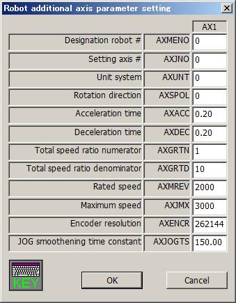
179 167


180 Collision detection You can set information related to the robot's collision detection functions. This function can be used with Version 3.2 or later of this software Warm-up operation You can set information related to the robot's warm-up function. This function can be used with Version 3.2 or later of this software. 168


181 Movement You can set information related to the optimum acceleration/deceleration for robot operation and set compliance errors. The information that can be set concerning movement parameters depends on the robot controller connected. This function can be used with Version 3.2 or later of this software. The controller version which can use this function is as follows. Maximum acceleration/deceleration correction ratio Compliance error function settings Optimum acceleration/deceleration setting Direction of gravity CR750/700 series Can be used with all versions CRn-500 series J2 or later H6 or later G1 or later H4 or later Command You can set parameters related to robot programs. This function can be used with Version 3.2 or later of this software. 169


182 User error You can set the message, cause, and recovery method for user errors set with a program. This function can be used with Version 3.2 or later of this software. Double tap the error number from the list or tap [Set...] button. The "User Error" edit screen is displayed. Double tap Tap Input the error number, error message, cause, and recovery method, then tap the [OK] button. The user errors input to the list are displayed. At this time, input an error number from "9000" "9200". Please note that the list display is not sorted by error number. 170

![If you select [MELFA-3D Vision] or [Network Vision Sensor (2D)] at [Auto configuration], the default value corresponding to each device is set](/docs-images/92/108480221/images/183-1.jpg "to items below [Mode].")
183 Ethernet You can set robot controller Ethernet information. This function can be used with Version 3.2 or later of this software. Select the device to edit and double tap. A screen is displayed for setting a variety of device information. If you select [MELFA-3D Vision] or [Network Vision Sensor (2D)] at [Auto configuration], the default value corresponding to each device is set to items below [Mode]. CAUTION Using a CRn-500 series robot controller When using Ethernet with a CRn-500 series robot controller, the "Ethernet interface" option is required. 171

184 Multiple CPU You can set the parameters related to the Multiple CPU to use the CR750-Q/CRnQ-700 series robot controller. These parameters can be set when you are connected to CR750-Q/CRnQ-700 series robot controller. This function can be used with Version 3.2 or later of this software. You can check the number of points input and range of total by tapping the [Check] button. Please refer to the manual of Universal model QCPU (QCPU User s Manual (Multiple CPU System)) for details of Multiple CPU setting. 172

185 CC-Link Set the information of CC-Link in the robot controller. This function can be used with Version 3.2 or later of this software. CAUTION This function can only be used with a CRn-500 series or CRnD-700 series robot controller. Also, this function cannot be used with CRnQ-700 series robot controller. If you use CRnQ-700 series robot controller, please set it with the software of the PLC. You can reset the error of the CC-Link interface card by tapping the [Err. Cancel] button. After that the same error doesn't occur. It is valid while the power supply of the Robot Controller is ON. When the power supply is turned OFF, the error comes to occur. 173

186 PROFIBUS Set the information of PROFIBUS in the robot controller. This function can be used with Version 3.2 or later of this software. CAUTION This function can only be used with a CRn-500 series or CRnD-700 series robot controller. Also, this function cannot be used with CRnQ-700 series robot controller. If you use CRnQ-700 series robot controller, please set it with the software of the PLC. You can reset the error of the PROFIBUS interface card by tapping the [Err. Cancel] button. After that the same error doesn't occur. It is valid while the power supply of the Robot Controller is ON. When the power supply is turned OFF, the error comes to occur. 174

187 I/O unit You can set information related to the I/O unit of the PLC. Set parameters while connected to the robot controller. This function can be used with Version 3.0 or later of this software. Moreover, the software version of the controller which can use this parameter is as follows. Controller S/W Ver. of the controller CR750-D/CRnD CR750-Q/CRnQ-700 Ver.R3 or later When a unit number in [Unit #] is specified, the parameter of the specified unit number is displayed in the PLC I/O unit. In the [IO sharing when using Multiple CPUs], it is set up whether XY signals read or they don t read After you change the parameter values, you can rewrite the parameters in the robot controller by tapping the [Write] button. 175

188 Work coordinate Work coordinate parameter defines coordinates used with the WORK jog. 8 work coordinates can be defined. The WORK jog function is available with Ver.2.3 or later of this software. Moreover, the software version of the controller which can use this function is as follows. Controller CR750-D/CRnD-700 CR750-Q/CRnQ-700 S/W Ver. of the controller Ver.P8 or later Ver.N8 or later The work coordinate is defined by 3 points; Origin WO, +X WX, and +Y WY. 176

189 Force control parameters You can set parameters of force control in robot controllers. The force control function can be used with Version 3.0 or later of this software. For details of these parameters, refer to the user s manual of the force control function. Controller CR750-D/CRnD-700 CR750-Q/CRnQ-700 S/W Ver. of the controller Ver.S3 or later Ver.R3 or later Force sensor Set the parameters, [Assign sensors], [Sensor coordinates], [Place / Angle], [Filter time constant], [Restriction], and [Tolerance level] which are used by the force control function. After you change the parameter values, you can rewrite the parameters in the robot controller by tapping the [Write] button. 177

![function. After you change the parameter values, you can rewrite the parameters in the robot controller by tapping the [Write] button. .3.](/docs-images/92/108480221/images/190-1.jpg "Force control characteristics Set the parameters, [Gain], [Instruction], and [Detection] which are used by the control feature of force control function.")
190 Force control mode Set the parameters, [Coordinate system], [Control mode of axes], [Stiffness coefficients], and [Dumping coefficients] which are used by the control mode of force control function. After you change the parameter values, you can rewrite the parameters in the robot controller by tapping the [Write] button Force control characteristics Set the parameters, [Gain], [Instruction], and [Detection] which are used by the control feature of force control function. The Mode switch judgment/speed reference button is displayed in this software 3.1 or later. The controller which can set the parameters [Mode switch judgment] and [Speed reference] is as follows. Table 17-6 Robot controller which can set the parameters [Mode switch judgment] and [Speed reference] Controller S/W Ver. of the controller CR750-D/CRnD-700 Ver.S3g or later CR750-Q/CRnQ-700 Ver.R3g or later (1) In the case of using version 3.0 or earlier 178

![parameters in the robot controller by tapping the [Write] button. 17.](/docs-images/92/108480221/images/191-1.jpg "4.27.4. Force log Set the parameters, [Configuration] and [FTP")
![setting] which are used by the force control function.](/docs-images/92/108480221/images/191-2.jpg "After you change the parameter values, you can rewrite the parameters")
191 (2) In the case of using version 3.1 or later After you change the parameter values, you can rewrite the parameters in the robot controller by tapping the [Write] button Force log Set the parameters, [Configuration] and [FTP setting] which are used by the force control function. After you change the parameter values, you can rewrite the parameters in the robot controller by tapping the [Write] button. 179

192 Real-time external control command Set the information of the Real-time external control (MXT). This function can be used with Version 3.2 or later of this software. 180
 It is possible to create the different definition files up to 10.")
193 User definition parameter In the User definition parameter window, it is possible to edit the parameters, which prepared by the definition files, at the one window. Create the definition files beforehand in PC, and copy the files to T/B. File name Paramxx.TXT (xx = 01 to 10) It is possible to create the different definition files up to 10. Folder in T/B to copy to / IPSM / MELFA / UserDef Please make the UserDef folder by yourself. Format of the parameter definition The 1st line : ; (semicolon) + title string The 2nd line (Example) ;Ethernet parameter NETIP; NETMSK; NETPORT; CPRCE11; COMDEV; NETMODE; NETHSTIP; MXTCOM1; MXTTOUT; : parameter name + ; (semicolon) One parameter name is written on one line, and these can be arrayed up to 10 line. 181
194 17.5. Find Strings can be found from the parameter list being displayed. Tap the [Find word] button, and enter the string you want to find in the find string field, and tap [Search] button. () The specified string is found from the current cursor position in the parameter list to the direction specified Power Reset of the Robot Controller To make modified parameters effective, it is necessary to power on the robot controller again. The power reset of the robot controller can be performed from T/B. After setting parameters, the power reset confirmation screen appears. To immediately reset the power, select [Yes]. () To set more parameters, set all the necessary parameters first, and then select [Yes]. (<b>) <b> 182

 Set the screen name when T/B is started to Top screen. 2) Set T/B brightness to Brightness.")
195 18. System option System option has system property setting functions. System option is shown by following operation. Version Menu System option Display On Display, set the screen name when T/B is started and T/B brightness. The operation is as follows. 1) Set the screen name when T/B is started to Top screen. 2) Set T/B brightness to Brightness. 3) Tap [Write] button. () User definition screen is supported by version 2.2 or later of this software. 183


196 18.2. Update T/B Update the T/B software. This function can be used with Version 3.2 or later of this software. Prepare the new version of the T/B software and the Update tool. Tap [Update] button. You can update the T/B software. Download the update data (compressed file). Copy the files which are decompressed of update data to root folder of the USB memory (ex. If USB memory s drive letter is D, copy them to D:/ ). Connect the USB memory to the T/B. Download the update data Compressed data (ZIP) Download MITSUBISHI FA Decompress Copy Update data 184
![After you tap button, you can see the screen as follows. Check the caution, and tap [OK] button, you can see the screen as follows.](/docs-images/92/108480221/images/197-1.jpg "Check the versions before and after update and cautions, and tap [Start] button, start update. CAUTION Please do not turn off the controller during update. If do that, the T/B may be broken.")
197 After you tap button, you can see the screen as follows. Check the caution, and tap [OK] button, you can see the screen as follows. Check the versions before and after update and cautions, and tap [Start] button, start update. CAUTION Please do not turn off the controller during update. If do that, the T/B may be broken. CAUTION Please do not remove a USB memory during update. If do that, the T/B may be broken. 185
![18.3. Language of T/B You can change the language of the T/B. Select the language () and tap [Write] button. 18.4. IP address of T/B You can set the IP address of the T/B. Tap [Setting] button ().](/docs-images/92/108480221/images/198-0.jpg "After you tap [Setting] button (), you can see the screen as follows. You can set IP address, Subnet Mask, and Default gateway.")
198 18.3. Language of T/B You can change the language of the T/B. Select the language () and tap [Write] button IP address of T/B You can set the IP address of the T/B. Tap [Setting] button (). After you tap [Setting] button (), you can see the screen as follows. You can set IP address, Subnet Mask, and Default gateway. If the T/B connect to the CRnQ controller, set the IP address with different only host address of the controller s IP address. You can confirm the controller s IP address by Ethernet parameter screen (refer to chapter 0). 186
199 19. User definition screen User definition screen is supported by version 2.2 or later of this software. You can make the customized screen by arranging the parts such as the button and the lamp that synchronize with the I/O signal. You can make two or more pages of definition screens. This screen can be used by the following usages. - This screen is used as an operation monitor. - When the state of T/B is enabling, the peripheral devices such as conveyers is made to work by the button on the screen. Parts that can be displayed on the user definition screen are as follows. List 19-1 List of parts Parts Explanation 1 Button The signal can be output from the robot controller by tapping the button. The signal can be output only in T/B Enabling state. 2 Lamp The lamp can be turning on/off by the state of the I/O signal. 3 Robot Variable The value of the specified variable can be displayed. information Exe lines The executing program lines can be displayed. Program name The executing program name can be displayed. Exe line num. The executing line number of the program can be displayed. Cur pos Current positional data of the XYZ coordinate system can be displayed. Cur jnt Current positional data of the joint coordinate system can be displayed. 4 Label The character string can be displayed. 187
 Tap the [MENU] button () of a T/B screen and display menu panel. (2) Tap the [Option] button (<b>) in the menu. The System option is displayed.")
200 19.1. User definition Editor It is necessary to make the User definition screen beforehand to use it. The User definition screen is edited on the system information screen. (1) Tap the [MENU] button () of a T/B screen and display menu panel. (2) Tap the [Option] button (<b>) in the menu. The System option is displayed. (3) You can edit by "User definition screen"(<c>) of "System option" window. <b> (Note) User definition screen is supported by version 2.2 or later of this software. <c> <8> <2> <9> <10> <11> <1> <6> <7> <3> <4> <5> Please refer to List 19-2 Explanation of user definition List 19-2 Explanation of user definition screen for the explanation. 188

201 List 19-2 Explanation of user definition screen Name Explanation <1> List The list of registered "User definition screen" is displayed. "User definition screen" is displayed in order as displayed here. <2> [Edit] Existing "User definition screen" is edited. <3> [Add] "User definition screen" is newly added. <4> [Copy] "User definition screen" is copied. <5> [Delete] "User definition screen" is deleted. <6> "User definition screen" that has been selected is moved to above. <7> "User definition screen" that has been selected is moved to below. <8> [Import] "User definition screen" preserved in USB memory is imported. <9> [Export] Selected "User definition screen" is exported in USB memory. <10> [Select all] "User definition screen" displayed in the list are all selected. <11> [Clear] A present selection is released Adding the new page. To make the new page of "User definition screen", tap [Add] button (). User definition screen window is displayed. Please refer to Page edit of "User definition screen" for the method of editing the page. 189
202 Edit of existing page To edit an existing User definition screen, tap [Edit] button () on the window after selecting the user definition screen edited from the list. The edit display of selected "User definition screen" is displayed. Please refer to Page edit of "User definition screen" for the method of editing the page. 190
203 Copy of page You can copy "User definition screen". To make the copy of existing "User definition screen", tap [Copy] button (<b>) after selecting the user definition screen from the list (). The copy of the selected user definition screen is made (<c>). The name of the copied user definition screen becomes "<Origin Name> copy ". <b> <c> Deletion of page To delete the existing "User definition screen", tap [Delete] button (<b>) after selecting the user definition screen from the list (). After the deletion confirmation message is displayed, tap the [Yes] button. <b> CAUTION Note that once "User definition screen" are deleted, they cannot be recovered. 191
204 Page edit of "User definition screen" The grid line () is displayed in the edit display of the user definition screen. Each part can be registered with the block unit (<b>) delimited in this grid line. <b> <1> <2> <3> <4> <1> Name : Page name is set. The name can be input by [Edit] button. <2> Line : The ruled line is drawn on "User definition screen". <3> Save : The content of the edit is preserved. <4> Close : The edit display is closed. When it closes without preserving, the attention message is displayed. 192
 After \"Select item\" window is displayed, tap [Button] button (<b>). (3) Set the button name, button size and the kind of button on \"Create button\" windows.")
205 Button (1) Tap the position (block) in which the button is made (). Left side of the button is arranged in this position. (2) After "Select item" window is displayed, tap [Button] button (<b>). (3) Set the button name, button size and the kind of button on "Create button" windows. (4) The movement of when the button is tapped is set by [Set] button (<c>). The set content is displayed in "Movement setting" (<d>). (5) After the setting is completed, tap [OK] button (<e>). <b> <1> <2> <3> <d> <c> <4> <e> <1> Name : The name of the button is set. The button name can be input by [Button name edit] button. The button name can be displayed by two lines by checking "2 lines". <2> Size : The width of the button can be set. The width of the button that can be set is 1/2/3. <3> Button type : The kind of the button can be set. Alternate When the button is tapped once, the button keeps ON state. And when the button is tapped again, it returns to OFF state. The signal output is kept too. Momentary The button keeps ON state while it is being pushed. 193
206 <4> Movement setting : The condition and the signal output operation when the button ON can be set. The condition can be selected as follows. Please set the signal number etc. when you make the signal state the condition. When the button is ON or OFF, the condition is judged. - Unconditionally - State of the specified Input signal - State of the specified output signal The signal output operation can be selected as follows. Please set the signal number etc. when you output the signal. - Done nothing - Output the specified output signal Operation setting can be set up to two. Two operation settings operate individually by using each condition. Moreover, when High and Low are set to output to the same signal, and both conditions become true, the Condition2 is given priority. If the operation is set signal output, when the button is OFF, the signal is output in the state opposite High/Low state at the time of ON. Example of setting the movement of button For example: The button that output signal number 20 to High when input signal number 20 is High. (1) A default value of Button operating condition window is shown in a right picture. (2) Set the condition of operation. Tap <d>, and select the signal type. When things except "Unconditionally" are selected, the input area of signal number and the combo box to select the state are displayed. Now, select "input signal". <d> 194
![(3) Tap [Signal No.] button (<e>), and input "20" to signal number (<f>). Tap the state of the signal (<g>), and select "High". Now, select "Input signal".](/docs-images/92/108480221/images/207-0.jpg "<f> <g> <e> (4) Select \"High\" as signal operation of when tapping on a button (<h>). <h> (5) The input area of output signal number is displayed. Tap [Signal No.")
207 (3) Tap [Signal No.] button (<e>), and input "20" to signal number (<f>). Tap the state of the signal (<g>), and select "High". Now, select "Input signal". <f> <g> <e> (4) Select "High" as signal operation of when tapping on a button (<h>). <h> (5) The input area of output signal number is displayed. Tap [Signal No.] button (<j>), and input "20" to the signal number (<i>). (6) After the setting is completed, tap [OK] button (<k>). <i> <j> <k> 195
![19.1.5.2. Lamp (1) Tap the position (block) in which the lamp is made (). The lamp is arranged at this position. (2) After Select item window is displayed, tap [Lamp] button (<b>).](/docs-images/92/108480221/images/208-0.jpg "(3) Select the lighting color of the lamp on Create lamp window.")
![(4) Tap [On/Off condition] button (<c>), and set the lighting condition and the turning off condition on "The lamp on/off condition window. Signal number can be set by [Signal No.] button (<e>).](/docs-images/92/108480221/images/208-2.jpg "After setting the lighting condition and the turning off condition, tap [OK] button (<f>). The set content is displayed (<d>) in the right of the [On/Off condition] button.")
208 Lamp (1) Tap the position (block) in which the lamp is made (). The lamp is arranged at this position. (2) After Select item window is displayed, tap [Lamp] button (<b>). (3) Select the lighting color of the lamp on Create lamp window. (4) Tap [On/Off condition] button (<c>), and set the lighting condition and the turning off condition on "The lamp on/off condition window. Signal number can be set by [Signal No.] button (<e>). After setting the lighting condition and the turning off condition, tap [OK] button (<f>). The set content is displayed (<d>) in the right of the [On/Off condition] button. (5) After setting the lamp color and lighting condition and the turning off condition, tap [OK] button (<g>). <b> <1> <2> <d> <c> <g> <e> <f> <1> Lamp color : The lighting color of the lamp can be selected. <2> Setting : The condition of turning on / turning off the lamp can be set. If only one condition is set, the lamp is operated like the other condition is set the opposite High/Low state to the same signal number. Moreover, when both the ON condition and the OFF condition are true, the ON condition is given priority. 196
209 Example of setting lamp ON/OFF For example: Lamp that is turned on when the input signal number 20 is High, and is turned off when the input signal number 20 is Low. (1) A default value of The Lamp on/off condition window is shown in a right picture. (2) Set On condition. Tap <h>, and Select the signal type. Now, select input signal. <h> (3) Tap [Signal No.] button (<j>), and set 20 to signal number (<i>). <i> <j> (4) Select "High" (<k>), as a state of signal to light the lamp. <k> (5) Similarly, set the condition for turning off the lamp, and tap [OK] button (<l>). <l> 197
 After \"Select item\" window is displayed, tap [Robot information] button (<b>). (3) Select \"variable\" (<c>) as the type on Create robot information window.")
![(4) After setting the information of the variable, tap [OK] button (<e>). <b> <c> <1> <2> <3> <4> <d> <5> <6> <7> <e> <1> Size : Set the width of box in which the variable is displayed.](/docs-images/92/108480221/images/210-2.jpg "The value from 1 to 16 can be set. <2> Slot : Select task slot number for which the variable is used. The range of slot number that can be set is different according to the system that uses it.")
210 Variable The value of the specified variable is displayed. (1) Tap the position (block) in which the variable is displayed (). Left side of the variable is arranged in this position. (2) After "Select item" window is displayed, tap [Robot information] button (<b>). (3) Select "variable" (<c>) as the type on Create robot information window. (4) After setting the information of the variable, tap [OK] button (<e>). <b> <c> <1> <2> <3> <4> <d> <5> <6> <7> <e> <1> Size : Set the width of box in which the variable is displayed. The value from 1 to 16 can be set. <2> Slot : Select task slot number for which the variable is used. The range of slot number that can be set is different according to the system that uses it. <3> Name : Set the variable name. Robot Status Variable also can be set. The name is input by [Edit] button (<d>). <4> Variable type : Select the variable type. <5> Edit : Select the edit permission of the variable. When set Enable, while displaying this screen, you can change the value of this variable by tapping this parts and displaying the input value screen. (Only at T/B state is enabling.) <6> Arrangement : Select the position in which the variable is arranged. <7> Color : Select the background color of the area where the variable is displayed. 198
 Tap the position (block) in which the content of the program is displayed (). Left side of the content of the program is arranged in this position.")
![(2) After "Select item" window is displayed, tap [Robot information] button (<b>). (3) Select "Exe line" (<c>) as the type on Create robot information window.](/docs-images/92/108480221/images/211-3.jpg "(4) After setting the information on the content of the program, tap [OK] button (<d>).")
211 Program execution content The content of the program being executed is displayed. The amount of 7 lines, the execution line, upper 3 lines and lower 3 lines, are displayed. (1) Tap the position (block) in which the content of the program is displayed (). Left side of the content of the program is arranged in this position. (2) After "Select item" window is displayed, tap [Robot information] button (<b>). (3) Select "Exe line" (<c>) as the type on Create robot information window. (4) After setting the information on the content of the program, tap [OK] button (<d>). <b> <c> <1> <2> When User definition screen is shown <3> <d> <1> Size : Set the width of box in which the content of program is displayed. The value from 1 to 16 can be set. <2> Slot : Select task slot number for which the program is executed. The range of slot number that can be set is different according to the system that uses it. <3> Color : Select the background color of the area where the content of program is displayed. 199
 After \"Select item\" window is displayed, tap [Robot information] button (<b>). (3) Select \"Program name\" (<c>) as the type on Create robot information window.")
212 Program name The name of program being executed is displayed. (1) Tap the position (block) in which program name is displayed (). Left side of the box is arranged in this position. (2) After "Select item" window is displayed, tap [Robot information] button (<b>). (3) Select "Program name" (<c>) as the type on Create robot information window. (4) After setting the information of program name, tap [OK] button (<d>). <b> <c> <1> <2> When User definition screen is shown <3> <4> <d> <1> Size : Set the width of box in which program name is displayed. The value from 1 to 16 can be set. <2> Slot : Select task slot number for which the program is executed. The range of slot number that can be set is different according to the system that uses it. <3> Arrangement : Select the position in which the program name is arranged. <4> Color : Select the background color of the area where the program name is displayed. 200
 After \"Select item\" window is displayed, tap [Robot information] button (<b>).")
213 Execution line number of program The line number of program being executed is displayed. (1) Tap the position (block) in which execution line number is displayed (). Left side of the box is arranged in this position. (2) After "Select item" window is displayed, tap [Robot information] button (<b>). (3) Select "Exe line num" (<c>) as the type on Create robot information window. (4) After setting the information of execution line number, tap [OK] button (<d>). <b> <c> <1> <2> When User definition screen is shown <3> <4> <d> <1> Size : Set the width of box in which execution line number is displayed. The value from 1 to 16 can be set. <2> Slot : Select task slot number for which the program is executed. The range of slot number that can be set is different according to the system that uses it. <3> Arrangement : Select the position in which execution line number is arranged. <4> Color : Select the background color of the area where execution line number is displayed. 201
 all together, please use Variable type and set the Robot Status Variable P_CURR. Please refer to 19.1.5.")
 After \"Select item\" window is displayed, tap [Robot information] button (<b>). (3) Select \"Cur pos\" (<c>) as the type on Create robot information window.")
![(4) After setting the information of the current position data (the XYZ coordinate system), tap [OK] button (<d>).](/docs-images/92/108480221/images/214-3.jpg "<b> <c> <1> <2> <3> When User definition screen is shown <4> <5> <d> <1> Size : Set the width of box in which the current position data (the XYZ coordinate system) is displayed.")
214 Current position data (the XYZ coordinate system) The current position data of robot is displayed with each XYZ coordinate system type axis. If you want to display the current position data (the XYZ coordinate system) all together, please use Variable type and set the Robot Status Variable P_CURR. Please refer to Variable" for details. (1) Tap the position (block) in which the current position data is displayed (). Left side of the box is arranged in this position. (2) After "Select item" window is displayed, tap [Robot information] button (<b>). (3) Select "Cur pos" (<c>) as the type on Create robot information window. (4) After setting the information of the current position data (the XYZ coordinate system), tap [OK] button (<d>). <b> <c> <1> <2> <3> When User definition screen is shown <4> <5> <d> <1> Size : Set the width of box in which the current position data (the XYZ coordinate system) is displayed. The value from 1 to 16 can be set. <2> axis : Select the displayed axis of the current position data (the XYZ coordinate system). <3> Robot # : Select the robot number which displays the current position data. <4> Arrangement : Select the position in which the current position data (the XYZ coordinate system) is arranged. <5> Color : Select the background color of the area where the current position data (the XYZ coordinate system) is displayed. 202
 all together, please use \"Variable\" type and set the Robot Status Variable \"J_CURR\". Please refer to \"19.1.5.")
 After \"Select item\" window is displayed, tap [Robot information] button (<b>). (3) Select \"Cur jnt\" (<c>) as the type on Create robot information window.")
215 Current position data (the joint coordinate system) The current position data of robot is displayed with each joint coordinate system axis. If you want to display the current position data (the joint coordinate system) all together, please use "Variable" type and set the Robot Status Variable "J_CURR". Please refer to " Variable" for details. (1) Tap the position (block) in which the current position data is displayed (). Left side of the box is arranged in this position. (2) After "Select item" window is displayed, tap [Robot information] button (<b>). (3) Select "Cur jnt" (<c>) as the type on Create robot information window. (4) After setting the information of the current position data (the joint coordinate system), tap [OK] button (<d>). <b> <c> <1> <2> <3> When User definition screen is shown <4> <5> <d> <1> Size : Set the width of box in which the current position data (the joint coordinate system) is displayed. The value from 1 to 16 can be set. <2> axis : Select the displayed axis of the current position data (the joint coordinate system). <3> Robot # : Select the robot number which displays the current position data. <4> Arrangement : Select the position in which the current position data (the joint coordinate system) is arranged. <5> Color : Select the background color of the area where the current position data (the joint coordinate system) is displayed. 203
 Tap the position (block) in which the label is made ().")
 After \"Select item\" window is displayed, tap [Label] button")
 After setting the label on Create label window, tap [OK]")
216 Label The label can be displayed at the specified position. (1) Tap the position (block) in which the label is made (). The label is arranged in this position. (2) After "Select item" window is displayed, tap [Label] button (<b>). (3) After setting the label on Create label window, tap [OK] button (<c>). The label name is set by [Label name edit] button (<d>). <b> <d> <c> 204
217 Save and end of editing user definition screen After the editing of user definition screen is completed, tap [Save] button (). To end the edit, tap [Close] button (<b>). <b> 205
 After \"Edit menu\" window is displayed, Tap [Edit] button (<b>). (3) The edit displays of selected parts are displayed.")
218 Edit of existing parts Edit of existing parts is as follows: (1) Tap a part which is edited (). (2) After "Edit menu" window is displayed, Tap [Edit] button (<b>). (3) The edit displays of selected parts are displayed. After changing contents, tap [OK] button (<c>). <b> <c> 206
![19.1.7. Copy/movement of parts Parts can be copied or be moved. (1) Tap the part to copy, and select it (). (2) After "Edit menu" window is displayed, tap [Copy] button (<b>).](/docs-images/92/108480221/images/219-1.jpg "When parts are moved, tap [Move] button. (3) Tap the position(block) where the part is copied onto (moved to).")
219 Copy/movement of parts Parts can be copied or be moved. (1) Tap the part to copy, and select it (). (2) After "Edit menu" window is displayed, tap [Copy] button (<b>). When parts are moved, tap [Move] button. (3) Tap the position(block) where the part is copied onto (moved to). At this time, the current position(block) of part is red, and the position(block) where the part is copied onto is green. Tap [Yes] button (<d>) on the confirmation message. <b> <c> <d> 207
![19.1.8. Deletion of parts Parts can be deleted. (1) Tap the part to delete, and select it (). (2) After "Edit menu" window is displayed, tap [Delete] button (<b>).](/docs-images/92/108480221/images/220-1.jpg "(3) Tap [Yes] button on the confirmation message. <b> 19.1.9. Change of page name Page name can be changed in [Edit] button () under the left of the window.")
220 Deletion of parts Parts can be deleted. (1) Tap the part to delete, and select it (). (2) After "Edit menu" window is displayed, tap [Delete] button (<b>). (3) Tap [Yes] button on the confirmation message. <b> Change of page name Page name can be changed in [Edit] button () under the left of the window. Caution When page name that has already been registered is input, it becomes an error. 208
![19.1.10. Edit of ruled line The ruled line can be drawn on the user definition screen. 19.1.10.1. Drawing the ruled line (1) Tap [Line] button () on the window.](/docs-images/92/108480221/images/221-1.jpg "(2) The button ( [Top],[Bottom],[Left],[Right] ) (<b>) for the ruled line is displayed in the right of [Line] button.")
![These buttons to draw the ruled line disappear when [Line] button (<c>) is tapped again. <c> <b> (3) Select the kind of ruled line (<d>).](/docs-images/92/108480221/images/221-2.jpg "Only one kind of the ruled line can be selected. <d> (4) Tap the block (<e>) where the ruled line is drawn.")
221 Edit of ruled line The ruled line can be drawn on the user definition screen Drawing the ruled line (1) Tap [Line] button () on the window. (2) The button ( [Top],[Bottom],[Left],[Right] ) (<b>) for the ruled line is displayed in the right of [Line] button. These buttons to draw the ruled line disappear when [Line] button (<c>) is tapped again. <c> <b> (3) Select the kind of ruled line (<d>). Only one kind of the ruled line can be selected. <d> (4) Tap the block (<e>) where the ruled line is drawn. The ruled line of the specified position on the selected block can be drawn. <e> <f> (5) After editing the ruled line, tap [Line] button (<f>) again. 209
![19.1.10.2. Erasing the ruled line (1) Tap [Line] button () on the window.](/docs-images/92/108480221/images/222-1.jpg "(2) The button ( [Top],[Bottom],[Left],[Right] ) (<b>) for the ruled line is displayed in the right of [Line] button.")
![These buttons to draw the ruled line disappear when [Line] button (<c>) is tapped again. <c> <b> (3) Select the kind of ruled line (<d>).](/docs-images/92/108480221/images/222-2.jpg "Only one kind of the ruled line can be selected. <d> (4) Tap the block (<e>) where the ruled line is erased.")
222 Erasing the ruled line (1) Tap [Line] button () on the window. (2) The button ( [Top],[Bottom],[Left],[Right] ) (<b>) for the ruled line is displayed in the right of [Line] button. These buttons to draw the ruled line disappear when [Line] button (<c>) is tapped again. <c> <b> (3) Select the kind of ruled line (<d>). Only one kind of the ruled line can be selected. <d> (4) Tap the block (<e>) where the ruled line is erased. The ruled line of the specified position on the selected block can be erased. <e> <f> (5) After editing the ruled line, tap [Line] button (<f>) again. 210

![.1.11.1. Import of page (Reading from USB memory) (1) Install the USB memory. (2) Tap [Import] button (). (3) Select the import file in USB memory on "Open" window, and tap [open] button.](/docs-images/92/108480221/images/223-1.jpg "(4) The selected user definition screen is added to the list.")
223 Import / Export of page The made user definition screen can be saved in USB memory or can be read from USB memory. Import : The user definition screen specified from USB memory is read. Export : The specified user definition screen is saved in USB memory. When [Import] button or [Export] button is tapped with USB memory not installed, the error is displayed Import of page (Reading from USB memory) (1) Install the USB memory. (2) Tap [Import] button (). (3) Select the import file in USB memory on "Open" window, and tap [open] button. (4) The selected user definition screen is added to the list. If the user definition screen of the same name has already been registered in the list, "import" is added to the name of the user definition screen Export of page(save to USB memory) (1) Install the USB memory. (2) Select the user definition screen to export (). If [Select all] button (<c>) was tapped, all the user definition screens can be selected. (3) Tap [Export] button (<b>). (4) Save it applying the file name on the screen for saving. <b <c> 211
![19.2. Operation of user definition screen The user definition screen can be displayed by the following operations. (1) Tap the [MENU] button () of a T/B screen and display menu panel.](/docs-images/92/108480221/images/224-1.jpg "(2) Tap the [User Definition] button (<b>) in the menu. (3) The user definition screen is displayed. <b> (Note) User definition screen is supported by version 2.2 or later of this software.")
224 19.2. Operation of user definition screen The user definition screen can be displayed by the following operations. (1) Tap the [MENU] button () of a T/B screen and display menu panel. (2) Tap the [User Definition] button (<b>) in the menu. (3) The user definition screen is displayed. <b> (Note) User definition screen is supported by version 2.2 or later of this software. <1> <2> <3> <4> <1> User definition screen : The registered user definition screen is displayed. On this screen, you can change the value of the variable parts set value edit Enable by tapping this parts and displaying the input value screen. (Only at T/B state is enabling.) <2> Page name : The name of the user definition screen is displayed. : The page is switched. <3> <4> CAUTION The signal can be output only in the T/B enabling state when the button is tapped. Enable the T/B state when the signal is outputted by the button which registered on the user definition screen. Please note that the signal cannot be output in the T/B disabling state. The state of the signal can be seen to regardless of the state of T/B. 212
225 Mechanism of screen update It takes 0.5 seconds or less to update the state of the lamp and robot information, and the update which cannot have been updated during that time is done after 0.5 seconds. For example, it becomes the following if there are 15 information items to update, and 10 items can be dealt by every 0.5 seconds. Get robot information (10 items) 0.5 sec. 0.5 sec. Get robot information (5 items) 0.25 sec. 0.5 sec. While getting robot information, the signal is not outputted by tap or tap the button. (1) The signal output by the button tapped or tapped is delayed 0.5 seconds or less. (2) When parts increase, the update interval of the lamp and robot information becomes longer. 213

 Tap the [MENU] button () of a T/B screen and display menu panel. (2) Tap the [Operation panel] button (<b>) in the menu. (3) The Operation panel screen is displayed.")
226 20. Operation panel The Operation panel is a screen prepared for the controller with whom the operation panel is not equipped. This screen has functions equal with controller's operation panel. This screen can be started by selecting the program. This screen is possible to use it even in "AUTOMATIC" and "MANUAL" mode. Operation panel is not displayed with the software before version 3.0. Moreover, the software version of the controller which can use this function is as follows Starting Controller CR750-D/CRnD-700 CR750-Q/CRnQ-700 S/W Ver. of the controller Ver.S3 or later Ver.R3 or later (1) Tap the [MENU] button () of a T/B screen and display menu panel. (2) Tap the [Operation panel] button (<b>) in the menu. (3) The Operation panel screen is displayed. (4) T/B Enable lamp (<c>) blinks at the "AUTOMATIC" mode. <b> <c> <d> <d> <d> Even if the operation screen is displayed, sheet key (<d>) can be used so far. 214

227 CAUTION When using it in the MANUAL mode - Push the TEACH button. (Change to the enabling state.) - Press this switch lightly when carrying out functions with the servo ON. The servo power cuts if an enable switch of T/B is opened while the robot is working and the robot stops. - The robot works below the speed limit of JOG. - The running program is immediately stopped, and the moving robot is decelerated to a stop when the JOG operation or the electric hand operation is done. After it stops, JOG operation and an electric hand can be operated usually Display <b> <e> <c> <d> The state of the slot 1(), the controller s operation mode (<b>), the controller s temperature (<c>) and the robot override (<d>) in the robot controller can be monitored. When lamp (<e>) of the button is lit or has blinked, the following state is shown. Button name Lighting Blinking Servo On The servo power on - Servo Off The servo power off - Start The controller is operating - Stop The controller is stopping. - Reset - The alarm is being generated as a controller. Cycle Stop - The controller is cycle stop. 215
![20.3. Program select The robot program can be selected at slot 1. (1) Tap the [Select] button ().](/docs-images/92/108480221/images/228-0.jpg "(2) [Select] dialog (<b>) is displayed.")
![(3) Select the program and Tap the [Select] button (<c>) (4) Since the confirmation screen is displayed,](/docs-images/92/108480221/images/228-1.jpg "the [Yes] button (<e>) is tapped.")
, and it raises it with [UP] button (<b>).")
228 20.3. Program select The robot program can be selected at slot 1. (1) Tap the [Select] button (). (2) [Select] dialog (<b>) is displayed. (3) Select the program and Tap the [Select] button (<c>) (4) Since the confirmation screen is displayed, the [Yes] button (<e>) is tapped. <a <b> <c> <d> <e> Note) The program selection cannot be done while executing the program Override UP/DOWN Override is lowered with [DOWN] button (), and it raises it with [UP] button (<b>). Upper and lower width in the operation panel screen is ten. Please note that upper and lower width is different with [ ] and [ ] of the sheet key of T/B. <b> 216
![20.5. Servo ON/OFF Tap the [Servo On] button (), the servo power is turned on. Tap the [Servo Off] button (<b>),the servo power is turned off. <b> 20.6.](/docs-images/92/108480221/images/229-0.jpg "Start automatic operation Tap the [Start] button (), the Caution dialog (<b>) is displayed. An automatic driving begins when [OK] button (<c>) is tapped after safety is confirmed.")
229 20.5. Servo ON/OFF Tap the [Servo On] button (), the servo power is turned on. Tap the [Servo Off] button (<b>),the servo power is turned off. <b> Start automatic operation Tap the [Start] button (), the Caution dialog (<b>) is displayed. An automatic driving begins when [OK] button (<c>) is tapped after safety is confirmed. <b> <c> CAUTION It is necessary to note that the robot works at a usual speed at the "AUTOMATIC" mode Stop Tap the [Stop] button (), the running program is immediately stopped, and the moving robot is decelerated to a stop. The servo power is hold turning on. 217
![20.8. Reset The [Reset] button () can be reset the controller s error. This also resets the program's halted state and resets the program.](/docs-images/92/108480221/images/230-0.jpg "At program reset Tap the [Reset] button (), the confirmation message box (<b>) is displayed. Tap the [Yes] button (<c>), the program is reset. <b> <c> 20.9.")
230 20.8. Reset The [Reset] button () can be reset the controller s error. This also resets the program's halted state and resets the program. At program reset Tap the [Reset] button (), the confirmation message box (<b>) is displayed. Tap the [Yes] button (<c>), the program is reset. <b> <c> Cycle stop If the [Cycle Stop] button () is tapped during the continuous operation, the program will stop after one cycle. The lamp (<b>) blinks during the cycle stop. It returns to a continuous operation when the [Cycle Stop] button (<a >) is tapped again during cycle stop. <b> 218
Mitsubishi Industrial Robot
 Mitsubishi Industrial Robot CRn-500 Series RT ToolBox Robot Total Engineering Support Software Instruction Manual (3A-01C-WINE/3A-02C-WINE) BFP-A8090-J Revision History Date of print Specifications No.
Product specification Articulated robot
 Product specification Articulated robot IRB 1600-5/1.2 IRB 1600-5/1.45 IRB 1600-7/1.2 IRB 1600-7/1.45 M2004 1 Description 1.1.1 Introduction Manipulator axes Axis 3 - Axis 4 + Axis 5 - + + - + - Axis 6
MISUMI SUPPORT SOFTWARE. RS-Manager. User s Manual C1 / C21 / C22 / P1 EXWM KE114. Ver. 2.00
 MISUMI SUPPORT SOFTWARE RS-Manager User s Manual C1 / C21 / C22 / P1 Ver. 2.00 EXWM14200 KE114 CONTENTS RS-Manager User s Manual Before getting started 1 1. About RS-Manager 2 2. Installing and uninstalling
USER MANUAL. TL400B Fingerprint Lock with Voice Guide Feature. Version: 1.1 Date: Jul. 2017
 USER MANUAL TL400B Fingerprint Lock with Voice Guide Feature Version: 1.1 Date: Jul. 2017 1 Content Read Before Use 1 Safety Caution 1 Structure 2 Basic Function 3 User Introduction 3 Operation and Voice
FD CONTROLLER INSTRUCTION MANUAL BASIC OPERATIONS MANUAL
 1302, TFDEN-002-006, 001 FD CONTROLLER INSTRUCTION MANUAL BASIC OPERATIONS MANUAL 6th edition Before attempting to operate the robot, please read through this operating manual carefully, and comply with
MITSUBISHI Mitsubishi Industrial Robot
 MITSUBISHI Mitsubishi Industrial Robot CRn-500 series INSTRUCTION MANUAL ADDITIONAL AXIS INTERFACE BFP-A8107-D Supplemental Instruction About the power supply synchronization with the robot controller.
Studuino Programming Environment Manual
 Studuino Programming Environment Manual Ver 0.9.7 Jun. 02, 204 This manual explains the Studuino Programming Environment and how to use it. As the Studuino Programming Environment develops, this manual
MELDASMAGIC MMI OPERATION MANUAL (FOR L/G) BNP-B2194 (ENG)
 BNP-B2194 (ENG)") MELDASMAGIC MMI OPERATION MANUAL (FOR L/G) BNP-B2194 (ENG) MELDASMAGIC is a registered trademark of Mitsubishi Electric Corporation. Microsoft and Windows are registered trademarks of Microsoft Corporation.
MELDASMAGIC MMI OPERATION MANUAL (FOR L/G) BNP-B2194 (ENG) MELDASMAGIC is a registered trademark of Mitsubishi Electric Corporation. Microsoft and Windows are registered trademarks of Microsoft Corporation.
XA-PA4 PC-Software XA-PA4. PC Software for XA-A Series Controllers. User s Manual. Rev SUS Corporation - 1 -
 XA-PA4 PC Software for XA-A Series Controllers User s Manual Rev 2.50-1 - XA-PA4 License Agreement Thank you for choosing XA-PA4. The following agreement must be agreed to use Software program, XA-PA4,
Data editing software EZED3
 HL-17149 Data editing software EZED3 OPERATING MANUAL Thank you for purchasing an Oriental Motor product. This Operating Manual describes product handling procedures and safety precautions. Please read
Connection Guide FANUC CORPORATION
 Machine Automation Controller NJ-series EtherCAT(R) Connection Guide FANUC CORPORATION R-30iB Robot Controller P605-E1-01 About Intellectual Property Rights and Trademarks Microsoft product screen shots
Spray hand manipulator control system
 Spray hand manipulator control system V3.0 VERSION Shenzhen Huacheng Industrial Control Co.,Ltd. CATALOGUE 1 SYSTEM CONFIGURATION AND INSTALLATION... 4 1.1 BASIC CONFIGURATION...4 1.2 SYSTEM INSTALLATION...
Software Manual. Version: H BENCHTOP ROBOT SOFTWARE USER GUIDE Version H
 Software Manual Version: H6.1.1.292 BENCHTOP ROBOT SOFTWARE USER GUIDE Version H6.1.1.293 Software Manual Table of Contents SECTION 1: INTRODUCTION... 5 1.1 Introduction...6 1.2 Safety...6 1.3 New Features...6
Battery Charging The tablet has a built-in rechargeable Li-polymer battery.
 Attention: This handbook contains important security measures and the correct use of the product information, in order to avoid accidents. Pls make sure to reading the manual carefully before use the device.
Standard specifications RS007LFF60
 Standard specifications RS007LFF60 December 05, 2017 KAWASAKI HEAVY INDUSTRIES, LTD. ROBOT DIVISION Materials and specifications are subject to change without notice. Specification : (Arm): (Controller):
Specifications. What s Inside The box
 Tablet of Contents Specifications.1 What s inside the box 1 Tablet Parts 2 Getting started...2 Connecting to the Internet..6 Task Bar..8 Install and Uninstall 9 Camera.10 HDMI.11 Trouble Shooting 11 Warranty..13
GAT Handheld Coder Pro+ User Manual
 GAT Handheld Coder Pro+ User Manual Rev 1.2 READ INSTRUCTION CAREFULLY BEFORE USE IF YOU HAVE ANY QUESTIONS ABOUT THE USE OF THIS DEVICE, CONTACT YOUR BIMMER RETROFIT REPRESENTATIVE BEFORE USE HANDHELD
DriveWizard Plus Instruction Manual
 DriveWizard Plus Instruction Manual To properly use the product, read this manual thoroughly. MANUAL NO. TOEP C730600 20C Table of Contents Safety Symbols and Markings...4 Manual Overview...5 Related Manuals...5
MEXE02. Support software OPERATING MANUAL
 HM-60131-5 Support software MEXE02 OPERATING MANUAL This manual describes the MEXE02 Ver. 3.10 and later. The screens and operation procedures in the MEXE02 Ver. 3.10 and later differ from those in versions
1. Introduction P Package Contents 1.
 1 Contents 1. Introduction ------------------------------------------------------------------------------- P. 3-5 1.1 Package Contents 1.2 Tablet Overview 2. Using the Tablet for the first time ---------------------------------------------------
HP Notebook PCs - Keyboard and TouchPad or ClickPad Guided Troubleshooter
 HP Notebook PCs - Keyboard and TouchPad or ClickPad Guided Troubleshooter This document applies to HP notebook computers. The keyboard, TouchPad, or ClickPad on your laptop is not working as expected:
RobovieMaker2 User Guide
 dedicated software for small CPU board VSRC003 RobovieMaker2 User Guide ATR Vstone Co., Ltd. Contents 1.Welcome-------------------------------------------------------------------------------5 1-1.Overview--------------------------------------------------------------------------------------5
2 1.1 Safety using methods Definition of warning symbols Standard accessories Installation...
 Table of Contents 1 Satety precautions... 2 1.1 Safety using methods...2 1.2 Definition of warning symbols...2 2 Standard accessories......6 3 Installation... 7 3.2 Leg frame... 7 3.3 Installation and
EQUIPMENT OPERATION MANUAL
 EQUIPMENT OPERATION MANUAL Loctite S440 Series SCARA Robots Book 2 of 4: Quick Start A Company FOR SAFE USE Safety Notes Read the following Warnings and Cautions thoroughly for the safe use of the Scara
Introduction. Summary. Otasuke GP-EX! Introduction Summary. Intro-21. Development Environment Intro-4. Procedures of Creating New Screen
 Introduction Summary Summary Intro-1 Development Environment Intro-4 Procedures of Creating New Screen Intro-5 Main Window Intro-6 Tips for man-hours reduction ~Full use of Work Space~ Intro-10 Simulation
Command Reference Manual
 YAMAHA NETWORK BOARD Command Reference Manual ENGLISH E E105-Ver. 1.0 Introduction Thank you for purchasing the PROFIBUS compatible module. This PROFIBUS compatible module is an option module that allows
How to Update NN3D to v2.07 (Combo Update) MFDBB
 MFDBB") How to Update NN3D to v2.07 (Combo Update) MFDBB 1. NN3D v2.07 Update Introduction MFDBB The combo update for the MFDBB requires a USB Jump Drive (USB flash memory stick). Additionally, a USB KEYBOARD
How to Update NN3D to v2.07 (Combo Update) MFDBB 1. NN3D v2.07 Update Introduction MFDBB The combo update for the MFDBB requires a USB Jump Drive (USB flash memory stick). Additionally, a USB KEYBOARD
Robot Controller RC700-A Option Teach Pendant TP3
 Rev.7 Robot Controller RC700-A Option Teach Pendant TP3 EM179F3507F ii Robot Controller RC700-A Option Teach Pendant TP3 Rev.7 Robot Controller RC700-A Option Teach Pendant TP3 Rev.7 Copyright 2015-2017
GTWIN 1.1 CONTROL TECHNOLOGY CORPORATION. GTWIN 2.8 Quick Start. MGT Panel & GTWIN Quick Start Guide
 GTWIN 1.1 CONTROL TECHNOLOGY CORPORATION GTWIN 2.8 Quick Start MGT Panel & GTWIN Quick Start Guide CONTROL TECHNOLOGY CORPORATION MGT Panel & GTWIN Quick Start Guide Copyright 2004-2007 Control Technology
Standard specifications BA006LFE01C01
 Standard specifications BA006LF01C01 ###### 1st dition : August 30, 2016 KAWASAKI HAVY INDUSTRIS, LTD. ROBOT DIVISION Materials and specifications are subject to change without notice. Specification :
EW SERIES SUPPORT SOFTWARE (FOR EW2C-H-NP, EW2C-H-CC) OWNER'S MANUAL (Ver. 1.0)
 OWNER'S MANUAL (Ver. 1.0)") X435178 Ver1.0 EW SERIES SUPPORT SOFTWARE (FOR EW2C-H-NP, EW2C-H-CC) OWNER'S MANUAL (Ver. 1.0) Contents 1. Software 1-1 Overview 2 1-2 System Requirements 2 2. Before You Begin 2-1 Preparation 3 2-2 Connecting
X435178 Ver1.0 EW SERIES SUPPORT SOFTWARE (FOR EW2C-H-NP, EW2C-H-CC) OWNER'S MANUAL (Ver. 1.0) Contents 1. Software 1-1 Overview 2 1-2 System Requirements 2 2. Before You Begin 2-1 Preparation 3 2-2 Connecting
CONTENTS INTRODUCTION... 2 GENERAL DESCRIPTION...
 CONTENTS INTRODUCTION... 2 GENERAL DESCRIPTION... 4 General View... 4 Turn the Device On/Off... 5 Navigate the Device... 6 Set the Target Language... 9 Address to a Male or Female... 10 Pronounce a Phrase
INSTRUCTION MANUAL OPERATION MANUAL PROGRAMMING MANUAL UNI-HOST MANUAL GAIN SETUP MANUAL ALARM CODE MANUAL. Robostar Robot Controller Manual
 Robostar Robot Controller Manual ROBOSTAR ROBOT N1 Series UNI-HOST MANUAL INSTRUCTION MANUAL OPERATION MANUAL PROGRAMMING MANUAL UNI-HOST MANUAL GAIN SETUP MANUAL ALARM CODE MANUAL www.robostar.co.kr Robostar
FAPT PICTURE & FPAssist
 FAPT PICTURE & FPAssist For Windows OPERATOR S MANUAL No part of this manual may be reproduced in any form. All specifications and designs are subject to change without notice. In this manual we have tried
TOSVERT VF-S15. My function-s setting Tool PCL001Z. Instruction Manual
 TOSVERT VF-S15 My function-s setting Tool PCL001Z Instruction Manual NOTICE 1. Read this manual before installing or operating. Keep this instruction manual on hand of the end user, and make use of this
Controller setting kit Software (ACT Controller)
") No.JXC -OMU0010 PRODUCT NAME Controller setting kit Software (ACT Controller) MODEL/ Series JXC-W2 series Contents 1. Safety Instructions... 2 2. Product Outline... 4 3. Operation explanation... 5 3.1
No.JXC -OMU0010 PRODUCT NAME Controller setting kit Software (ACT Controller) MODEL/ Series JXC-W2 series Contents 1. Safety Instructions... 2 2. Product Outline... 4 3. Operation explanation... 5 3.1
EQUIPMENT OPERATION MANUAL
 EQUIPMENT OPERATION MANUAL Loctite 200, 300, and 400 Series Benchtop Robots Book 1 of 4: A Company FOR SAFE USE Safety Notes Read the following Warnings and Cautions thoroughly for the safe use of the
3700 SERIES USER MANUAL
 SAFETY GUIDE This manual contains the precautions necessary to ensure your personal safety as well as for protection for the products and the connected equipment. These precautions are highlighted with
PFXGP4501TADC. Pro-face Xycom GP4000 PFXGP4501TADC
 PFXGP4501TADC http://www.axcontrol.com/automation/pro-face/gp-4000/pfxgp4501tadc Pro-face Xycom GP4000 PFXGP4501TADC Pro-face Xycom GP-450xT GP450xT Touch Screen Operator Interface 10.4 TFT Analog Color
Using the Android teach-pad
 with ROBWIN 7 and ROBOFORTH II v15/16 Components The components of the system are: 7 inch hand-held tablet Android software (apk or app ) already loaded. Bluetooth adaptor Serial port on rear of controller
Operation Manual (B) KVR-2418 (24L) Fanuc OiMD CNC. KENT INDUSTRIAL (USA) INC Edinger Ave., Tustin, CA 92780
 KVR-2418 (24L) Fanuc OiMD CNC. KENT INDUSTRIAL (USA) INC Edinger Ave., Tustin, CA 92780") Operation Manual (B) KVR-2418 (24L) Fanuc OiMD CNC KENT INDUSTRIAL (USA) INC. 1231 Edinger Ave., Tustin, CA 92780 Tel: (714) 258-8526 Fax: (714) 258-8530 Internet: WWW.KENTUSA.COM KENT USA THE WAY TO AFFORDABLE
Operation Manual (B) KVR-2418 (24L) Fanuc OiMD CNC KENT INDUSTRIAL (USA) INC. 1231 Edinger Ave., Tustin, CA 92780 Tel: (714) 258-8526 Fax: (714) 258-8530 Internet: WWW.KENTUSA.COM KENT USA THE WAY TO AFFORDABLE
Machine Controller MP900/MP2000 Series New Ladder Editor USER'S MANUAL
 YASKAWA Machine Controller MP900/MP2000 Series New Ladder Editor USER'S MANUAL YASKAWA MANUAL NO. SIEZ-C887-13.2B Copyright 2001 YASKAWA ELECTRIC CORPORATION All rights reserved. No part of this publication
PLCMDVR54 DASH CAM. Rearview Backup and Driving HD Camera Record Kit 1080p Night Vision Cam Video Recording System
 PLCDVR54 DASH CA Rearview Backup and Driving HD Camera Record Kit 1080p Night Vision Cam Video Recording System CONTENTS 1 (1) BASIC PARAETERS... 2 (2)... 3 1 DVR POWER ON/OFF...4 2 DRIVING RECORD FUNCTION...4
Instruction Manual for Teaching Device
 Shenzhen Han`s Motor S&T Co.,Ltd Instruction Manual for Teaching Device V 3.3 2017-07-19 Directory 1 Introduction... 1 2 Installation instruction...1 2.1 DCS and teaching device installation... 1 3 Software
Computer Basics Written by Brian O'Rooney. Copyright 2000 Nanaimo Literacy Association All rights reserved
 Written by Brian O'Rooney Copyright 2000 Nanaimo Literacy Association All rights reserved Windows is a registered trademark of Microsoft Corporation. This product/publication includes images from WordPerfect
There are 18 types of errors as follows. Simulator Interpreter Parser Motor control Servo Vision Calibration
 8. Troubleshooting 8.1 Error Code Table Events Events Warnings Controller Main Operator Panel Teach Pendant PC There are 18 types of errors as follows. Simulator Interpreter Parser Motor control Servo
Be sure to read the attached "TO ENSURE SAFE AND CORRECT USE" prior to use. Otherwise, it may cause an unexpected accident or fire.
 CE6000 SERIES CUTTING PLOTTER SETUP MANUAL MANUAL NO.CE6000-UM-8M4 Preface Thank you for choosing this product. Carefully keep this manual in a handy location for quick reference as necessity prior to
M2500 Engine Controller Configuration Manual
 M2500 Engine Controller Configuration Manual Revision: 08-04-2011 Page 1 Contents 1 Preface... 4 2 Configuration from front panel... 5 2.1 Engine Controller Configuration... 6 2.1.1 RPM settings... 6 2.1.2
& Technical Specifications
 User Manual & Technical Specifications User manual Contents Pidion BM-170 Technical specifications... 2 Micro Rolltalk basic package... 3 Micro Rolltalk functions and buttons... 3 Preparing Micro Rolltalk...
Handbook. CLIÉ handheld basic operations. Exchanging and updating files/data using the HotSync operation. Entering text on your CLIÉ.
 A-BU6-100-11 (1) CLIÉ handheld basic operations Exchanging and updating files/data using the HotSync operation Entering text on your CLIÉ handheld Customizing your CLIÉ handheld (Preferences) Exchanging
Studuino Programming Environment Manual
 Studuino Programming Environment Manual Created 04//0 Revised 07/0/3 Version History Date Content 04//0 First version 07/0/6 Updated for new Studuino website 07/03/8 Revised with added features for Windows
MITSUBISHI ELECTRIC CORPORATION
 MITSUBISHI Changes for the Better Mitsubishi Electric Corporation Industrial MELFA Technical News Robot BFPA60790215E* January 2018 Subject: Precautions of replacement from RH6SDH to RH6FRHD Applicable
Webster Release Notes Rev. A, March 1, 2008
 Webster Release Notes Rev. A, March 1, 2008 Overview This document contains release notes for PolyVision s Webster. Webster Software version 3.6 supports one of the most technologically advanced whiteboard
MRZJW3- SETUP154E. General-Purpose AC Servo Servo Configuration Software MODEL INSTALLATION GUIDE
 General-Purpose AC Servo Servo Configuration Software MODEL MRZJW3- SETUP154E INSTALLATION GUIDE Thank you for choosing the Mitsubishi general-purpose AC servo Servo Configuration Software. To optimize
Robot Controller RC700 / RC90 Option Teach Pendant TP1
 Rev.5 Robot Controller RC700 / RC90 Option Teach Pendant TP1 EM16XP3305F ii Robot Controller RC700 / RC90 Option Teach Pendant TP1 Rev.5 Robot Controller RC700 / RC90 Option Teach Pendant TP1 Rev.5 Copyright
Press the PEN HOME key to move the pen(s) to the outside of the chart. The pen(s) is automatically raised off the chart.
 to the outside of the chart. The pen(s) is automatically raised off the chart.") DICKSON GETTING STARTED 7-day chart rotation 0 to 100 o F KT8P0/2/3 & KT856 Remote Sensing Temperature Recorder QUICK START 1. Remove the protective pen cap(s). 2. Connect Probe(s): a. KT8P0/2/3: Make
DICKSON GETTING STARTED 7-day chart rotation 0 to 100 o F KT8P0/2/3 & KT856 Remote Sensing Temperature Recorder QUICK START 1. Remove the protective pen cap(s). 2. Connect Probe(s): a. KT8P0/2/3: Make
1. Introduction P Package Contents 1.
 1 Contents 1. Introduction ------------------------------------------------------------------------------- P. 3-5 1.1 Package Contents 1.2 Tablet Overview 2. Using the Tablet for the first time ---------------------------------------------------
X-SEL Serial Communication Protocol Specification (Format B)
") X-SEL Serial Communication Protocol Specification (Format B) [Applicable Models] X-SEL-J/K Main Application V0.99 X-SEL-JX/KX Main Application V0.42 TT Main Application V0.18 X-SEL-P/Q Main Application
X-SEL Serial Communication Protocol Specification (Format B) [Applicable Models] X-SEL-J/K Main Application V0.99 X-SEL-JX/KX Main Application V0.42 TT Main Application V0.18 X-SEL-P/Q Main Application
LOREX CLIENT 3.0 SOFTWARE MANUAL IRMS Integrated Remote Management Software
 LOREX CLIENT 3.0 SOFTWARE MANUAL IRMS Integrated Remote Management Software Instruction Manual English Version 2.0 Copyright 2007 Lorex Technology Inc. www.lorexcctv.com Table of Contents Overview... -
EVOBOOK 2. User s Manual.
 EVOBOOK 2 User s Manual www.evolio.ro 0 User s Manual Content Page Introduction.... 2 Parts and Controls.... 3 Getting Started...... 6 Turning On/Off EvoBook2. 6 Charging EvoBook2... 6 Inserting SD card....
User's Guide. For CarChip and CarChip E/X 8210 & 8220
 User's Guide TM For CarChip and CarChip E/X 8210 & 8220 Product Number: 8210, 8220 Davis Instruments Part Number: 7395.064 DriveRight CarChip User s Manual Rev A (January 2, 2003) Davis Instruments Corp.,
TA0139 USER MANUAL ARDUINO 2 WHEEL DRIVE WIRELESS BLUETOOTH ROBOT KIT
 TA0139 USER MANUAL ARDUINO 2 WHEEL DRIVE WIRELESS BLUETOOTH ROBOT KIT I Contents Overview TA0139... 1 Getting started: Arduino 2 Wheel Drive Wireless Bluetooth Robot Kit using Arduino UNO... 1 2.1. What
Hybrid DVR Quick Start Guide
 Hybrid DVR Quick Start Guide Thank you for purchasing our product. If there is any question or request, please do not hesitate to contact dealer. This manual is applicable to most Hybrid DVR models. DVR
Tablet PC. Android 5.1 User Manual
 Tablet PC Android 5.1 User Manual Tablet of Contents Specifications. What s inside the box Tablet Parts Getting started... How to use TF card How to connect to PC Connection to Internet.. Camera. Trouble
User Manual. User Program(GUI) Function
 Function") User Manual User Program(GUI) Function - Table of Contents - 1. Installation and Connection of the Program... 4 1.1 Installation Environment of PC... 4 1.2 User Program(GUI) Installation Method... 4 1.3
User Manual User Program(GUI) Function - Table of Contents - 1. Installation and Connection of the Program... 4 1.1 Installation Environment of PC... 4 1.2 User Program(GUI) Installation Method... 4 1.3
MELFA Technical News BFP-A E-A
 MITSUBISHI Changes for the Better Title Mitsubishi Electric Applicable models Industrial Precautions for Replacing RH20SDH/20SQH with RH20FHD/Q RH20SDH,RH20SQH RH20FHD, RH20FHQ Robots MELFA Technical News
2015/09/24. M-Touch
 M-Touch 2.00.12 VERSION HISTORY (> 1.00) Graphics Maps: by means of Graphic Maps it s possible to display the alarm zones simply by tapping icons on the map shown on keypad screen. It s very simple to
JANOME SCARA/GANTRY ROBOT. JS/JSG Series. JANOME DESKTOP ROBOT JR2000N Series. Operation Manual. <PC Operation>
 JANOME SCARA/GANTRY ROBOT JS/JSG Series JANOME DESKTOP ROBOT JR2000N Series Operation Manual Thank you for purchasing the Janome Robot. *Read this manual thoroughly in order to properly use this robot.
YAMAHA Robot Controller. MRCH/QRCH/QRCX Series UNIT OWNER'S MANUAL
 YAMAHA Robot Controller MRCH/QRCH/QRCX Series UNIT OWNER'S MANUAL Safety Precautions (Always read before starting use) Always read this manual, the robot controller instruction manual and programming manual
MANUAL PELITT MINI 1
 MANUAL PELITT MINI 1 TABLE OF CONTENTS 1. Warnings 3 2. Getting Started 3 3. Your Phone 4 4. File Manager 4 5. Phone book 4 6. Fun&Games 4 7. Call center 4 8. Messaging 4 9. Multimedia 5 10. Organizer
Introduction to Computers By Jennifer King, YA and Marketing Librarian, Great Bend Public Library
 Introduction to Computers By Jennifer King, YA and Marketing Librarian, Great Bend Public Library Welcome and Introduction To better understand how to use computers, this course will teach you some basic
BEAT 2.0 USER MANUAL
 BEAT 2.0 USER MANUAL FCC ID: 2ADLJBEAT20 The device complies with part 15 of the FCC Rules. Operation is subject to the following two conditions: (1) This device may not cause harmful interference, and
DX200 OPTIONS MECHATROLINK-II COMMUNICATION FUNCTION INSTRUCTIONS
 DX200 OPTIONS MECHATROLINK-II COMMUNICATION FUNCTION INSTRUCTIONS (FOR MP2110-ET3 MADE BY YASKAWA ELECTRIC CORPORATION ) Upon receipt of the product and prior to initial operation, read these instructions
LME Software Block Quick Reference 1. Common Palette
 LME Software Block Quick Reference Common Palette Move Block Use this block to set your robot to go forwards or backwards in a straight line or to turn by following a curve. Define how far your robot will
WHAT TO DO IF THE SERVO SYSTEM REPORTS FAILURES.
 WHAT TO DO IF THE SERVO SYSTEM REPORTS FAILURES. 1. Try a hard reset on the system, shut the computer down and turn the main power switch off for 30 seconds, turn the main power back on and run the mango
Date 18/05/17. Operation and maintenance instructions for driver configurator QSet
 Operation and maintenance instructions 28 1. General recommendations The recommendations regarding safe use in this document should be observed at all times. Some hazards can only be associated with the
QL-1110NWB. Applications for Use with Computers. Applications for Use with Mobile Devices. Quick Setup Guide (English) NOTE
 NOTE") D00ZC6001 QL-1110NWB Quick Setup Guide (English) Thank you for purchasing the QL-1110NWB Label Printer! Read the Product Safety Guide first, then read this Quick Setup Guide for the correct setup procedure.
D00ZC6001 QL-1110NWB Quick Setup Guide (English) Thank you for purchasing the QL-1110NWB Label Printer! Read the Product Safety Guide first, then read this Quick Setup Guide for the correct setup procedure.
DX200 OPTIONS INSTRUCTIONS
 DX200 OPTIONS INSTRUCTIONS FOR ARM INTERFERE CHECK FUNCTION Upon receipt of the product and prior to initial operation, read these instructions thoroughly, and retain for future reference. MOTOMAN INSTRUCTIONS
Engineering Tool for PC SDWP001 Operating Manual
 Inverter HF-520/HF-X20 Series SF-520 Series Engineering Tool for PC SDWP001 Operating Manual 1 Manual No. DM2308E-1 Table of Contents Safety Symbols and Markings...4 Safety Notes and Instructions...4 Manual
JXC-W1 (JXC#3 Series)
") Product Name Controller Setting Software (For 4-axis Step Motor Controller) MODEL/ Series/ Product Number JXC-W1 (JXC#3 Series) Contents 1. Safety Instructions... 3 2. Product Specifications... 5 2.1 Features
Product Name Controller Setting Software (For 4-axis Step Motor Controller) MODEL/ Series/ Product Number JXC-W1 (JXC#3 Series) Contents 1. Safety Instructions... 3 2. Product Specifications... 5 2.1 Features
User Manual. pdoc Pro Client for Windows. Version 2.1. Last Update: March 20, Copyright 2018 Topaz Systems Inc. All rights reserved.
 User Manual pdoc Pro Client for Windows Version 2.1 Last Update: March 20, 2018 Copyright 2018 Topaz Systems Inc. All rights reserved. For Topaz Systems, Inc. trademarks and patents, visit www.topazsystems.com/legal.
Network Video Recorder Quick Operation Guide
 Network Video Recorder Quick Operation Guide UD.6L0202B1351A01 TABLE OF CONTENTS NVR Pre-Installation... 2 NVR Installation... 2 Hard Disk Installation... 2 Front Panels... 6 DS-9500NI-ST/RT Front Panel...
About this manual. Notices for use
 4SK606 Contents About this manual...1 Notices for use...1 Know the product...2 Using the Original Dash Cam 2...3 Charging...3 Inserting the microsd card...4 Powering ON/OFF the Dash Cam...4 Installing
Safety Instructions. Product information
 Safety Instructions Do not disassemble, or drop the camera from high altitude. Do not expose the camera to high temperatures and avoid contact with water and other liquid substances. After long time using,
Conveyor System Utilizing Safety Observation Function
 Conveyor System Utilizing Safety Observation Function [System Configuration] GOT Q06UDEHCPU Q172DSCPU QY40P Q173DSXY Axis 1 Axis 2 No.2 Conveyor axis No.1 Conveyor axis [Mitsubishi solution] Motion CPU:
* IMPORTANT * REGISTERING YOUR MACHINE
 * IMPORTANT * REGISTERING YOUR MACHINE Thank you for your purchase of the Keyline 994 Laser. Before continuing with machine setup and use, please complete the following; COMPLETE PRODUCT REGISTRATION FORM
Contents Using the 4SK909 Twister
 Contents About this manual... 1 Notices for use... 1 Know the product... 2 Using the 4SK909 Twister... 3 Charging... 3 Inserting the TF memory card... 4 Powering ON/OFF the Dash Cam... 4 Installing in-vehicle
PhotoScanner. User Guide
 User Guide Contents 1. Introduction 1. Features 2. Safety 3. Product Specifications 4. Package Contents 5. Product Description 6. Settings 7. Settings 8. Settings 9. Settings 10. Settings 11. Using the
Overview 1. Foreword 2. Warnings
 Overview 1. Foreword Thank you for choosing our product. Please read this manual carefully before using the product. Specifications and software updates may be subject to change without notice. Some pictures
Mitsubishi Simple Motion Module MELSEC-Q Series QD77MS4
 Mitsubishi Simple Motion Module MELSEC-Q Series QD77MS4 Sample Screen Manual Mitsubishi Electric Corporation Using the Samples The sample screen data and files such as the instruction manual can be used
TS-X/TS-P. Features. 1 Main operation patterns
 Single axis Positioner / Robot positioner Dedicated I/O point tracing TS series are positioner type controllers that only performs point trace. No program is needed. Operation is simple. After setting
DT800 Lane Timer Manual
 DT800 Lane Timer Manual Features: 1) 8000 Memories 2) Built-in PRINTER 3) Up to10 Lane Buttons 4) PC Upload Function 5) 12/ 24Hr User-selectable Clock 6) 4-Digit Bib Number 7) 4-Digit Place Counter 8)
Downloaded from manuals search engine
 INDEX 1. DVR Features...1 2. Layout 2.1 Front Panel...1 2.2 Rear Panel...2 2.3 Remote Control...2 3. Installation 3.1 Installing the Hard Drive...3 3.2 Connecting Camera and Monitor...3 3.3 Connecting
SANYO DENKI Servo Amplifier SANMOTION R and Pro-face AGP-3****-CA1M/LT Connection Procedure. Instruction Manual. Version1.0 (
 SANYO DENKI Servo Amplifier SANMOTION R and Pro-face AGP-3****-CA1M/LT Connection Procedure Instruction Manual Version1.0 (2009.2.25) Table of Contents 1 Applicable devices... 1 2 Installation of GP-Pro
QUICK START GUIDE. Setting up your AccuDate XL for use with the Jolt App
 QUICK START GUIDE Setting up your AccuDate XL for use with the Jolt App ACCUDATE XL QUICK START GUIDE Welcome....1 Package Contents Review.... 2 Setting Up Your AccuDate XL... 3 Powering Up and Shutting
Features & Specifications V
 Features & Specifications V18.0919 KEEP THE IRON. UPGRADE YOUR MACHINE. A Turnkey Solution to easily replace your Fadal Control Utilize your existing AC/DC servo components and wiring Replace your old
Mitsubishi Motion Controller CPU MELSEC-Q Series Q173DCPU. Sample Screen Manual. Mitsubishi Electric Corporation
 Mitsubishi Motion Controller CPU MELSEC-Q Series Q173DCPU Sample Screen Manual Mitsubishi Electric Corporation Using the Samples The sample screen data and files such as the instruction manual can be used
GPS+CAMTM. User Manual VS55020
 VS55020 GPS+CAMTM User Manual Congratulations on purchasing the Vision System. This innovative product integrates the functions of a front view car video recorder, a rear view monitoring system, and GPS
Slide the switch to On and the player will be powered on in 1 second. The player will prompt "Welcome" and then enter the main interface.
 NMV-179X For the correct use and good performance of the player, the user must fully understand the manual as well as strictly follow the instructions provided. Avoid high temperature (above 35 C) or
IN5132/IN5142/IN5134/IN5134a IN5144/IN5144a/IN5135/IN5145 User's Manual (detailed) Instant Stack Guide
 Instant Stack Guide") Projector IN5132/IN5142/IN5134/IN5134a IN5144/IN5144a/IN5135/IN5145 User's Manual (detailed) Instant Stack Guide Thank you for purchasing this product. Features This projector can be used in conjunction
Projector IN5132/IN5142/IN5134/IN5134a IN5144/IN5144a/IN5135/IN5145 User's Manual (detailed) Instant Stack Guide Thank you for purchasing this product. Features This projector can be used in conjunction