Deseo KNX Manual. Deseo KNX. Manual. basalte bvba hundelgemsesteenweg 1a 9820 merelbeke belgium. 1 / 65 v basalte
|
|
|
- Annis McKenzie
- 5 years ago
- Views:
Transcription
1 Deseo KNX basalte bvba hundelgemsesteenweg 1a 9820 merelbeke belgium 1 / 65 v basalte
2 Table of contents: 1. Introduction Installation Identifying the parts Front view of the electronics Rear view of the electronics Front cover General Navigation Navigation controls Navigation structure Multitouch Screen standby Menu pages Start page Time Date Temperature Variable text Fixed text Scenes Lights Switched light page Dimmed light page Motors Short / long press behaviour Short press behaviour Temperature Temperature mode page Temperature setpoint page Ventilation page Music Music source page Music on/off / 65 v basalte
3 4.6.3 Music preset page Music volume page Volume page with no feedback Volume page with slider (0-100) Volume page with slider (0-255) Volume page with 14-byte object Playing page Info General functions Displayed text Touch sensor calibration Cleaning object State polling Internal thermostat Functions (heating/cooling) Modes and automatic mode selection Presence object Window object Setpoint Temperature control method point control method PI control Temperature control output PWM Continuous Configuration of parameters General Multitouch Text for up and down Temperature sensor Menu s Scenes Lights Motors Temperature / 65 v basalte
4 Thermostat Music Info Version Appendix: Characters main menu font (blue) Characters submenu font (white) Characters information font (small white/orange) List with communication objects / 65 v basalte
5 1. Introduction Deseo is designed to control all the different functions in one single room in a very simple and intuitive way, through the integrated 1.7 oled display. With one single touch, it is possible to operate any lighting circuit, control different scenes, operate the central music system, control the sunscreens, or operate the heating, air conditioning and ventilation using the built-in thermostat. The innovative tactile technology, typical for basalte products, allows all these functions with extreme ease of use in a sleek and refined design. 5 / 65 v basalte
6 2. Installation Use a standard European back box with screws to mount the Deseo switch. The distance between the screws must be 60mm. The screws must be installed vertically. Using screws that are too big might hinder the mounting of the Deseo front cover onto the Deseo switch. When mounted, the Deseo front cover should hide the Deseo switch completely. If not, the connection to the Deseo front cover might not work properly, which will result in a reduced sensitivity of the switch! When fixing the screws, do not apply too much force since this will deform the plastic surrounding opening F. Doing so might hinder the installation of the Deseo front cover onto the Deseo switch! The minimal depth required for the Deseo switch KNX is 24mm. Additional depth should be reserved for connecting the device. Connect the 29V of the switch with a DC power supply between 18V and 36V. Each device has a power consumption of 20mA in standby mode, with a peak of 50mA (1.2 Watt). Please take into account that the power consumption at start-up can be higher. Make sure that the power supply is well grounded and correctly dimensioned! Prefer an over-dimensioned power supply, please reserve 2W for each device. Make sure that the temperature sensor is on the bottom side of the switch. Before installing the front cover, shut down the power supply of the switch. The device can be powered up after the installation of the front cover. Make sure that the power is down for at least 30 seconds to allow correct calibration. The small opening in the front cover is specially made for the temperature sensor. Make sure that the opening is at the bottom side of the switch. 6 / 65 v basalte
7 2.1 Identifying the parts Front view of the electronics A B C D E F G H I J 1.7 OLED-display Touch sensor up Touch sensor down Touch sensor left Touch sensor right Opening to screw the device into the wall box Guide for the Deseo front cover Temperature sensor Led left Led right B A I D J E C H G F 7 / 65 v basalte
8 2.1.2 Rear view of the electronics K L M N Programming button Programming led External power supply KNX connector K L 29V KNX M N Front cover O P Q R S T Display Touch sensor up Touch sensor down Touch sensor left Touch sensor right Opening temperature sensor P O R S T Q 8 / 65 v basalte

9 3. General The Deseo device has 4 touch sensitive areas which are used to navigate through the menus. The display shows only what will be controlled. All the pages and texts can be modified using ETS. Note: This manual is accurate starting from build number Navigation Navigation controls UP LEFT RIGHT DOWN Deseo has four touch sensitive fields: The UP, DOWN, LEFT and RIGHT buttons. Any touch surface can be used to wake the display. This will show the first active page. Normally this is the start page, if the start page is not active, the first main menu item will be displayed. If there is only one main menu item enabled, the first page of this menu will be displayed. Use the UP and DOWN buttons to browse through the main menus. At the desired main menu, use the RIGHT button to browse through the menu items. Use the LEFT button to go back to the main menu. Touching the LEFT sensor from the main menu will force the display to return to the start screen. If the start screen is disabled, the first active main menu item will be shown. Please refer to Navigation structure. At the desired function menu item, use the UP and DOWN button to control the current function. Labels at the top and bottom of the screen will provide more information about the current function of the UP and DOWN button. The white led s on the left and right sides indicate whether or not the LEFT and RIGHT button are enabled. The text on the start screen and the main menus are displayed in a blue font. The text on the function pages is displayed in a white font. 9 / 65 v basalte
10 Touching the upper and lower surface of the device simultaneously will trigger the multitouch event. Please refer to Multitouch. After some time, the display will go into standby-mode. Please refer to 3.2 Screen standby. 10 / 65 v basalte
11 3.1.2 Navigation structure Start screen Main menu Function menu Start page Scenes 1 Object 1 Scene 1 Object 2 Scene 1 Object 3 Scene 1 Object 4 Scene 1 Object 5 Scene 1 Object 6 Scene 1 Scenes 2 Object 1 Scene 2 Object 2 Scene 2 Object 3 Scene 2 Object 4 Scene 2 Object 5 Scene 2 Object 6 Scene 2 Lights 1 Object 1 Light 1 Object 2 Light 2 Object 3 Light 3 Object 4 Light 4 Object 5 Light 5 Object 6 Light 6 Lights 2 Object 1 Light 7 Object 2 Light 8 Object 3 Light 9 Object 4 Light 10 Object 5 Light 11 Object 6 Light 12 Motors 1 Object 1 Motor 1 Object 2 Motor 2 Object 3 Motor 3 Object 4 Motor 4 Object 5 Motor 5 Object 6 Motor 6 Motors 2 Object 1 Motor 7 Object 2 Motor 8 Object 3 Motor 9 Object 4 Motor 10 Object 5 Motor 11 Object 6 Motor 12 Temperature Mode Setpoint Ventilation Music Source Preset Volume Now playing Info Object 1 Info 1 Object 2 Info 2 Object 3 Info 3 Object 4 Info 4 Object 5 Info 5 Object 6 Info 6 11 / 65 v basalte
12 3.1.3 Multitouch A multitouch event occurs when the user simultaneously touches the upper and lower surfaces of the device. This function allows the user to trigger an action without browsing the menus. Typically, the multitouch is used to switch on and off the lights when a person enters or leaves the room. The installer can set text fields which are displayed shortly when multitouch occurs. The multitouch logic can also be triggered by a communication object (communication object 200). This action will not be shown on the display of the Deseo, it will only trigger its functionality. To control the multitouch, the device has to know the feedback of the lights. For this, there are 8 communication objects (communication objects 8-15) to couple the feedback of the lights controlled by the multitouch. When one or more feedback objects are active (1), the multitouch will send the off command. When all feedback objects are inactive (0), the multitouch will send the on command. 3.2 Screen standby To reduce power consumption and prolong display life, the display shuts down after a prolonged time of inactivity. This time can be configured with ETS. The device automatically wakes up when one or more buttons are touched or when the screen wake object is activated (if enabled). After 60 seconds, the display always goes back to the start screen. It only turns off after the timeout. If the timeout is shorter than one minute, the display will switch off, but touching a surface during this minute will show the last active screen. 12 / 65 v basalte
13 4. Menu pages 4.1 Start page The start page is the main entry, shown when the device wakes up. The page can display a variety of useful elements like time, date, text, temperature. In ETS, a predefined combination of elements can be set: Time and date Time and temperature Time and variable text Fixed text and temperature Fixed text and variable text Remark: If this page is disabled, the first page shown will be the first active menu page Time The device contains an internal clock that can be set with the according communication object (communication object 185). The time format can be set either in 12h or 24h notation. Accuracy is however limited. The time should be updated on a regular base and after each restart of the device with the according communication object. After restarting, the Deseo will show the time 9: Date The date can be set in various date formats (dd-mm-yyyy), (mm-dd-yyyy) and (yyyy-mm-dd). This date can be set with the according communication object (communication object 186). The date should be updated on a regular base and after each restart of the device with the according communication object. After restarting, the Deseo will show the date 31/12/ Temperature The device contains an internal temperature sensor. If an external sensor is used, the weighting of the internal and external values can be set in order to calculate the current actual value. The displayed temperature is limited between 0 C and 99.9 C or 0 F and 150 F. The temperature units ( C or F) can be configured Variable text The page can display variable text, coming from a 14-byte communication object. When the imported text does not fit on the display, the last characters are discarded. 13 / 65 v basalte
14 4.1.5 Fixed text A fixed text line can be added to the start page. The text can be entered in ETS. A maximum of 9 characters can be displayed. If the text does not fit on the display, the last characters are discarded. 14 / 65 v basalte
15 4.2 Scenes There are 2 scene pages, with up to 6 scenes per page. For every page there is one communication object. A scene page allows a user to recall a scene, saved in an actuator or another external memory location. It consists of a scene name and a square indicator at the bottom of the screen. When the down button is pressed, the scene is recalled and a white line appears under the scene label for 2 seconds. When scene save is enabled, the user can save the current light settings in the selected scene using the up button. If the button is pressed for at least 3 seconds, a save label appears at the top of the screen and the settings are saved. Each scene optionally contains a blocking function allowing the user to block certain external functions while a scene is active. The blocking object is sent out simultaneously with the scene number. This can be used for example to block a motion detector. 15 / 65 v basalte
16 4.3 Lights There are 2 light pages of 6 light objects each. Each light object can be switched or dimmed Switched light page The switched light page shows the name of the corresponding light circuit, an on label at the top and an off label at the bottom, defining the function of the buttons. It allows the user to switch on and off light circuits using a single 1-bit communication object. A line underneath the light label gives a visual indication of the status of the circuit. When the up button is pressed, the light is switched on and a white line appears under the lights label. Every time the button is pressed the on command will be sent, even if the light was already on. When the down button is pressed, the light is switched off and the white line disappears under the lights label. Every time the button is pressed, the off command will be sent, even if the light was already off. When feedback data is received, the indicator will be updated Dimmed light page A dimmed light page shows the name of the corresponding light circuit, a slider, an up label at the top and a down label at the bottom, defining the function of the buttons. It allows the user to switch on and off light circuits using a 1-bit communication object and to dim the circuit using a 4- bit communication object. It offers a visual indication of the status of the circuit using a 1 byte communication object. When the up button is pressed shortly (less than 1 second), the light is switched on using a 1-bit communication object. The slider increases to maximum. When the down button is pressed shortly (less than 1 second), the light is switched off using a 1- bit communication object. The slider decreases to minimum. When the up button is pressed longer than 1 second, the light dims up using a 4-bit communication object. The slider increases as long as the button is pressed. When the down button is pressed longer than 1 second, the light dims down using a 4-bit communication object. The slider decreases as long as the button is pressed. If a value is sent to the light n value feedback (input), the slider is updated with this value. Feedback values can be either 0-100% or For an intuitive look and feel, the ramp time of the slider has to be equal to the ramp time of the dimmer. This ramp time of the slider can be set into the parameters of the device. Remark: The feedback will not be updated while the slider is moving. 16 / 65 v basalte
17 4.4 Motors There are 2 motor pages with 6 motor objects each. A motor page allows the user to control blinds, shutters, curtains, etc. The page consist of a label with the name of the selected motor and an open label at the top and a close label at the bottom of the screen, defining the function of the buttons. Each motor page has a set of four 1-bit communication objects: Up short Up long Down short Down long For ease of use, 2 types of behaviour can be set: Short / long press behaviour Short press behaviour Short / long press behaviour This setting is the most straightforward. When a button is pressed shortly, the corresponding shortpress object is activated. The motor will be activated for a short period, allowing moving in steps. When a button is pressed longer than 2 seconds, the corresponding longpress object is activated. The motor will be activated until the motor reaches the end position Short press behaviour This setting is more convenient for controlling curtains and screens. It does not require the use of long and short presses. When a button is pressed, the corresponding longpress object is activated. A second press within the activation time of the motor will issue a shortpress, stopping the motor. For the correct operation of this function, the time required to open the curtain or blind fully, has to be defined in ETS. 17 / 65 v basalte
18 4.5 Temperature The temperature control includes 3 main items: Temperature mode page Setpoint page Ventilation page Temperature mode page The mode page allows the user to set the mode of the thermostat function. The user can choose mode Comfort, Standby and Economy. A 4 th mode Building protection cannot be chosen by the user but will be activated when the thermostat s functions are inhibited due to an external event (e.g. an open window) When the up button is pressed, the mode is set to a higher setting. When the highest setting is reached, the square indicator on the top of the screen disappears and the up button is disabled. When the down button is pressed, the mode switches to a lower setting. When the lowest setting is reached, the square indicator on the bottom of the screen disappears and the down button is disabled. For each mode there is a 1-bit communication object. The mode is also available through a 1-byte communication object, where the value represents the mode: 1: Comfort 2: Standby 3: Economy 4: Building protection Any input on the input communication objects overwrites the current mode setting. When a 0 to 1 transition is received on a 1-bit object, or an appropriate value on the 1-byte object, the mode state is overwritten and the screen is updated. 18 / 65 v basalte

19 4.5.2 Temperature setpoint page When the up or down button is pressed, the setpoint increases/decreases in steps of 0.5 C (1 F) or to the nearest 0.5 C (1 F) step in case it is send external. When the up or down key is held for longer than 1.5 seconds, the setpoint will increase/decrease every 0.5 seconds until the button is released. When the upper limit is reached, the + sign on the top of the display disappears and the upper button is disabled. When the lower limit is reached, the - sign on the bottom of the display disappears and the lower button is disabled. The temperature setpoint limits are set in the ETS temperature menu. The output functionality depends on the setting of the thermostat (internal / external mode). External mode When the external mode is selected, the thermostat will be controlled by an external logic. Deseo will only send its setpoint (communication object 96: Setpoint comfort Output) as set on the display. Every update will trigger an update on the communication object. By receiving an update on the setpoint (communication object 95: Setpoint comfort Input), sent by another device, the Deseo will overwrite the internal setpoint and the screen will be updated, even if the temperature setpoint is beyond the upper or lower limit. Remark: When a value is sent to the setpoint (input) communication object, the Deseo will not send a new actual setpoint (output) on the bus because this will occur an infinitive loop. Internal mode When the internal mode is activated, the functionality of the thermostat is regulated by the Deseo. There are 4 different types of thermostat regulations: Heating Cooling Heating/Cooling (manual) Heating/Cooling (automatic) A symbol for heating or cooling is displayed to indicate the current heating/cooling mode. In 2 state and PWM mode, the symbol will be brighter when the heating/cooling output is activated. In the internal mode, there are 2 communication objects which reflect the setpoint, an actual setpoint and a comfort setpoint. The comfort setpoint is the setpoint in the comfort mode. The actual setpoint is the setpoint value depending on the current mode (comfort/standby/economy). 19 / 65 v basalte
20 At reception of an update on the input setpoint (communication object 95), sent by another device, the Deseo will overwrite the internal setpoint and the screen will be updated, even if the temperature setpoint is beyond the upper or lower limit. The value is comfort based and will be recalculated using the current mode and temperature offsets between the modes. Remark: When a value is sent to the setpoint (input) communication object, the Deseo will send a new actual setpoint (output) on the bus. For more information about the internal thermostat, refer to 6. Internal thermostat Ventilation page The ventilation can be configured with 2 states (High, Low) or with 3 states (High, Mid, Low) When the up button is pressed, the ventilation state is set to a higher setting. When the highest setting is reached, the square indicator on the top of the screen disappears and the up button is disabled. When the down button is pressed, the ventilation state is set to a lower setting. When the lowest setting is reached, the square indicator on the bottom of the screen disappears and the down button is disabled. The output (communication object ) is only updated when the modified ventilation state is stable for 1.5 seconds or when the ventilation page is left. In that case, any active state will become inactive first and the new state will be activated 0.5 seconds later. When a 0 to 1 transition is received on any ventilation feedback object, the ventilation state is overwritten and the screen is updated. 20 / 65 v basalte
21 4.6 Music To control the music, the user can control the source, preset and the volume. There is also an additional page that shows the now playing information. Additionally, next and previous controls can be shown on this page Music source page When the up button is pressed, the next music source is selected. When the highest setting is reached, the square indicator on the top of the screen disappears and the up button is disabled. If the music was off, the first source will be selected and the music system will be switched on. When the down button is pressed, the previous music source is selected. When the lowest setting is exceeded, the music is turned off, the square indicator on the bottom of the screen disappears and the down button is disabled. A source is selected if the source is on the display for 1.5 seconds, or when the source page is left. When a source is selected, the corresponding communication object will send the numeric value corresponding to that source. In addition, the selection of a source will send a 1-bit communication object. Furthermore, a 1-bit communication feedback object can show if the music is on or off. Any appropriate value on the corresponding communication object of the source feedback will select the relevant source and update the screen Music on/off The method used for switching the music system on and off can be configured using ETS. Off = 0, on = 1 This setting is the most straightforward and sends a high level on the music on/off communication object for switching on and a low level for switching off the music. Off = 0, on = 1, when off send source 1 second later This setting is equal to the previous but will additionally send the source number 1 second after the on command, allowing the sound system to power up. Off = 1 This setting sends a high level for the music system to switch off. Remarks: When a 1 is received on the music on/off feedback communication object, the last active source is activated and the music on command is issued. When a 0 is received, the source feedback will be set to off, and if any sound related screen is active, the screen will return to the start page. 21 / 65 v basalte
22 4.6.3 Music preset page When presets are enabled, this page allows the user to set the preset for the selected source. The up and down key are used to navigate through the list of presets. When the last preset is exceeded, the first preset is presented again, forming an infinite loop. A preset is selected if the preset is on the display for 1.5 seconds, or when the preset page is left. When a preset is selected, the corresponding communication object will send the corresponding selected numeric value. When preset feedback is disabled, each time the preset page is entered, there is no preset selected and the preset title is displayed. The previous preset value will not be overwritten as long as no new preset is selected. When preset feedback is enabled, the preset value is preserved on re-entry of the preset menu. When an appropriate value is received on the corresponding communication object, the preset will be updated to the corresponding settings, and the screen will be updated. 22 / 65 v basalte
23 4.6.4 Music volume page To control the volume of the system, there are 4 possible ways: Volume page with no feedback Volume page with slider (0-100) Volume page with slider (0-255) Volume page with 14-byte object Remark: This page cannot be disabled Volume page with no feedback This type of page, which requires no feedback, consists of a volume label with adjustable text and two icons that represent the up and down buttons. When the upper button is pressed, the 4-bit communication object (communication object 150) sends the increase command (0x9) as long as the button is touched. When the button is released, the break command (0x0) is sent. Another option is a 1-bit communication object (communication object 148) which is active as long as the button is pressed. When the lower button is pressed, the 4-bit communication object (communication object 150) sends the decrease command (0x1) as long as the button is touched. When the button is released, the break command (0x0) is sent. Another option is a 1-bit communication object (communication object 149) which is active as long as the button remains pressed Volume page with slider (0-100) This type of page generates the same output as the page without feedback. In addition, the page shows a slider which is sliding up while the up button is pressed and sliding down while the down button is pressed. When a feedback value is received on the corresponding communication object (communication object 151), the slider is updated with this value. A value of 100 represents a full slider. Any value greater than 100 results in a full slider. For an intuitive look and feel, the ramp time of the slider has to be equal to the ramp time of the sound system. Remark: The feedback will not be updated while the slider is moving Volume page with slider (0-255) This type of page generates the same output as the volume page without feedback. In addition, the page shows a slider which goes up while the up button is pressed and down as long as the down button is pressed. When a feedback value is received on the corresponding communication object (communication object 151), the slider is updated with this value. A value of 255 represents a full slider. 23 / 65 v basalte
24 For an intuitive look and feel, the ramp time of the slider has to be equal to the ramp time of the sound system. Remark: The feedback will not be updated while the slider is moving. 24 / 65 v basalte
, the displayed text will be updated with this value. 4.6.")
25 Volume page with 14-byte object This type of page generates the same output as the volume page without feedback. In addition, the page shows a text element. When a feedback value is received on the corresponding communication object (communication object 152), the displayed text will be updated with this value Playing page This type of page allows the user to read extra information about the track played by the sound system. It contains a title, 1 or 2 information lines and optional controls to change to the next or previous track. The title is a string that can be defined in ETS for each source. The information lines for track title and artist can be provided by a set of eight 14-byte communication objects, 2 for each possible source (communication object 153 to 160). When a text value is received on one of the two available communication objects for that page, the information lines will be updated. The controls, which are optional, allow the user to start the next or the previous track for the current source. The output mode for the controls can be set in ETS. The next or previous command can be issued with two 1-bit communication objects (communication object 189/190/192/193/195/196/198/199), or through one 8-bit communication object (communication object 188/191/194/197). In that case, a command value for both commands needs to be set in ETS. When controls are enabled, the playing page will show a previous and next icon at the top and bottom of the screen. 25 / 65 v basalte
26 4.7 Info The info page can display useful information which is available on the bus in many formats. The information is read only. The page consists of a name and a value, optionally with units. The values can be 1-bit, 1-byte, 2-bytes or 14-byte data. For each page, a respective communication object is available. For 1-bit data, a label for false and a label for true can be configured. For numeric data, a variety of units are available. If the text does not fit on the display, the last characters are discarded. This is why there are 2 font sizes, small and large. In case there is not much information to show, the large font can be selected. When it is necessary to display more text, the small font can be selected. Using the info screen pointer, an info page can be displayed without browsing through the menu. To use this feature, write a value (1 to 6) to the communication object to show page 1-6. This feature is especially useful for high priority messages like alarms. To avoid that the device goes into standby after timeout, it is possible to cyclically write to the menu pointer object to keep the screen awake. 26 / 65 v basalte
27 5. General functions Displayed text All the text fields of the device can be defined within ETS. When an invalid character is filled in, the device will replace this character by a point (.). If the device expects a text value input but it is empty, it will show 3 points ( ) Touch sensor calibration The touch sensors need calibration to compensate for environment changes. At start-up, this calibration is performed automatically. Internal drift compensation will track slow variations. Quick changes in the environment (installation or removal of front cover) will necessitate recalibration. In most cases automatic recalibration is performed without user intervention. When manual recalibration is required, the user can force this by touching one or more buttons for 20 seconds. The device will restart and calibration is performed. Another option is to use a communication object to trigger the recalibration. While calibrating, the software build number will be shown on the display. Remark: Do not touch the front cover during recalibration because this can lead to insensitive sensors! Cleaning object The cleaning object allows the user to clean the surface of the device without activating the touch buttons. As long as there is a 1 on the corresponding communication object, the screen shows the Basalte logo and the buttons are disabled. To release the screen, write value 0 to the communication object. After the release, the display returns to the start-up screen State polling At start-up, Deseo polls all relevant communication objects for their status. To reduce bus load, only 1 state is requested per second. All irrelevant communication objects are skipped. 27 / 65 v basalte


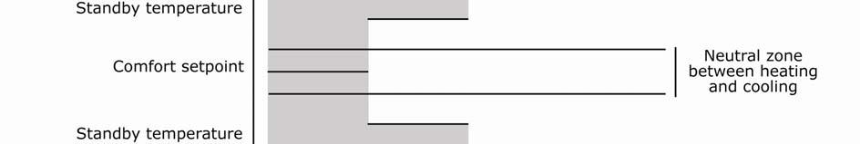
28 6. Internal thermostat 6.1 Functions (heating/cooling) The internal room temperature controller can control the temperature of 1 room. The device supports 4 operating options: Heating Cooling Heating and cooling manual Heating and cooling automatic In automatic and manual mode, the actual mode is indicated with an icon in the temperature setpoint page. In manual mode, the function is controlled by a communication object In Automatic mode, the function is automatically set by the controller. Heating mode is activated if the temperature falls below comfort setpoint neutral zone / 2. Cooling mode is activated if the temperature rises above comfort setpoint + neutral zone / 2. This neutral zone can be set between 2 and / 65 v basalte
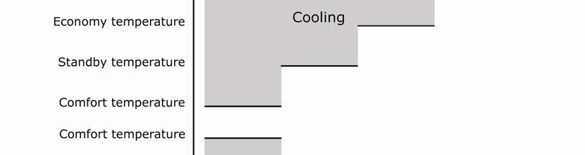
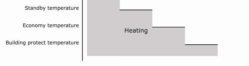
29 6.2 Modes In each option, the controller can work in 4 modes. Each mode has a setpoint assigned to it. Comfort: To be activated when people are present in the room. The temperature is set to a comfortable value. This value is a reference for the calculation of all other setpoint values. Standby: To be activated when the room is not in use. The temperature is set to a standby value which allows energy saving. Economy: To be activated when a room is not in use for a longer period (e.g. at night). The temperature is set to a low value. Building protection: When a window is opened, normal operation is suspended. The temperature is kept between critical values, preventing freezing and/or overheating. Only the first 3 modes can be selected by the user. Protection is a mode that will automatically be activated when a window is opened (if enabled) and automatic mode selection The normal operating modes: comfort, standby and economy can be selected using the mode menu or by the according communication objects. If enabled, the mode can be overridden to protect if a window is open. The mode can also be automatically defined using a presence object Presence object The presence object allows the user to automatically switch to the appropriate mode, depending on the presence in a room. When the presence object is active, the mode is set to comfort. When the presence object is inactive, the mode changes to standby or economy, depending on the settings Window object When the window object is enabled, normal operation of the thermostat is suspended if the object is active. The mode automatically changes to Protect. The user cannot override this setting and can no longer manually set other temperature related parameters. If a temperature related screen was active, the active screen is left and the start screen appears. In Building protect mode, only frost protection and/or overheating protection are active, keeping room temperature between critical values. If the window object returns to low, the thermostat resumes normal operation with the previously active settings. The window object can be configured to be activated on high or low. 29 / 65 v basalte


30 6.3 Setpoint For each function there is a setpoint assigned to each mode. The function heating and cooling automatic share the same setpoint for heating comfort and cooling comfort. The function heating and cooling manual has 2 different setpoint values, one for heating comfort and one for cooling comfort. The setpoint for standby and economy mode are derived from the comfort setpoint. This deviation, called an offset, for standby and economy can be set into the parameters of ETS. This deviation is kept constant against the changes to the comfort setpoint. The setpoint for building protect is a fixed setpoint for the heating and cooling mode. When external logic is used, there is only 1 setpoint, not linked to mode or function. When the up or down button is pressed, the setpoint increases/decreases in steps of 0.5 C or 1 F or to the nearest 0.5 C of 1 F step. When the up or down key is held for longer than 1.5 seconds, the setpoint will increase/decrease every 0.5 seconds. 30 / 65 v basalte


31 31 / 65 v basalte
32 6.4 Temperature control method point control method This is a very simple controller method, suitable for slow responding cooling and heating systems. It addresses the actuator with 1 bit output variable. No proportional value is calculated. This type of method results is a significant temperature fluctuation. For heating: When the temperature rises above the setpoint, the actuator is deactivated. When the temperature falls below setpoint hysteresis, the actuator is activated. The hysteresis is a value that can be set between 10 and 60. For cooling: When the temperature falls below above the setpoint, the actuator is deactivated. When the temperature rises below setpoint + hysteresis, the actuator is activated. The hysteresis is a value that can be set between 10 and PI control PI control is a feedback control method that combines proportional and integral actions. The proportional action provides smooth control without overshoot or oscillation. This action s output is proportional to the temperature deviation. When the temperature deviation is equal to the proportional band, the output is 100%. The integral action s output is proportional to the time over which the deviation occurred. This action output reaches the same level as the proportional action after a specified time: the reset time. The integral action automatically corrects offset, created by the proportional action. To avoid windup, the I-action is limited. The proportional band and reset time are adjustable in ETS. 32 / 65 v basalte
33 6.5 Temperature control output In case of a 2-point controller, there is a single 1-bit output for the actuator. No parameterization is required. In case of a PI controller, the controller output type can be set to PWM or Continuous PWM A PWM output uses a single 1 bit output. By adjusting the pulse / pause ratio, averaged over time, it behaves like a proportional output. Output values smaller than 10% are discarded and values exceeding 90% result in pulse / pause ratio of 100%. In this regard, please keep in mind that the valve needs a certain time to open or close. The time to open or close the valve should be at least 10% of the cycle time. The PWM period (duration of 1 pulse + 1 pause) can be parameterized. When the PWM output is 0%, only the falling edge is sent every cycle. When the PWM output is 100%, only the rising edge is sent every cycle Continuous A continuous output uses a 1-byte unsigned output and directly reflects the proportional output of the PI controller. The output value is updated every 20 seconds or when de value is changed by more than 5%. 33 / 65 v basalte
 Cleaning object This parameter allows to enable/disable the touch sensors with a communication object.")
34 7. Configuration of parameters 7.1 General Parameter Timeout for display to switch off in sec Description This parameter sets the time that the display will remain active after the last use. Range: seconds (default: 30 seconds) Cleaning object This parameter allows to enable/disable the touch sensors with a communication object. Disable (default) Enable 0: cleaning object 34 / 65 v basalte
35 Screen wake object This parameter allows waking the screen with an external communication object. Enable Disable (default) 1: screen wake Behaviour: The display becomes active when 0 to 1 transition is received on the according communication object. This is a similar behaviour of touching a touch sensor when the device is into standby. Calibration object This parameter allows calibrating the device with an external communication object. Enable Disable (default) 2: calibration Behaviour: The touch sensors of the device start to calibrate on a rising edge of the communication object. While calibrating, the display shows the status of the calibration process and the software build number into the device. Start-up screen This parameter allows to define the start screen text Disable (default) Time (24h) + temperature Time (12h) + temperature Time (24h) + date (dd.mm.yyyy) Time (24h) + date (mm.dd.yyyy) Time (24h) + date (yyyy.mm.dd) Time (12h) + date (mm.dd.yyyy) Time (12h) + date (dd.mm.yyyy) Time (12h) + date (yyyy.mm.dd) Text + temperature (fixed text + temperature) Time (24h) + 14 byte object (time + variable text) Time (12h) + 14 byte object (time + variable text) Text + 14 byte object (fixed text + variable text) 185: time 186: date 187: start screen (text input) Temperature format This parameter allows changing the temperature format Display all temperature in C (default) Display all temperature in F 35 / 65 v basalte
36 7.1.1 Multitouch Parameter Multitouch function Description This parameter enables or disables the multitouch function. To achieve a toggle function, the status of the light circuits in the room can be fed back to the status feedback objects. Enable Disable (default) 8-15: multitouch status feedback n (input) Behaviour: When one or more feedback objects are active, the multitouch will send the off command. When all feedback objects are inactive, the multitouch will send the on command. Mode This parameter sets the mode of text which has to be displayed when a multitouch occurs. No text display Text display (default) Text on Text off Output This parameter sets the displayed text for the on command of the multitouch (default: room on). This parameter sets the displayed text for the off command of the multitouch (default: room off). This parameter defines the on and off command of the multitouch. 1 bit on/off(default) Scene on / scene off Scene on / all off Remark: Scene numbers between 1 and 64 4: multitouch - on/off (output) 5: multitouch - scene number (output) 6: multitouch - all off (output) Scene number on This parameter defines the scene number for scene on. Value between 1 and 64 Scene number off This parameter defines the scene number for scene off. Value between 1 and / 65 v basalte
37 Scene blocking object This parameter enables or disables the additional scene blocking object corresponding with the multitouch output. Blocking (default) No blocking 7: multitouch - blocking object (output) Behaviour: The blocking object is set to 1 as long as the scene is active. Multitouch external trigger object This parameter enables or disables the multitouch external trigger object. Enable (default) Disable 200: multitouch - external trigger (input) Behaviour: This function makes it possible to trigger the multitouch command from an external device, for example from a Sentido. The rising edge of the communication object triggers the multitouch command Text for up and down Parameter Scene save Switch object up Switch object down Dim object up Dim object down Motor object up Motor object down Description This parameter sets the text displayed when saving a scene. This parameter sets the text displayed as up command on a light switching page. This parameter sets the text displayed as down command on a light switching page. This parameter sets the text displayed as up command on a light dimming page. This parameter sets the text displayed as down command on a light dimming page. This parameter sets the text displayed as up command on a motor page. This parameter sets the text displayed as down command on a motor page. 37 / 65 v basalte
38 7.1.3 Temperature sensor Parameter Compensation for int. temperature sensor Description This parameter makes it possible to compensate the measured temperature. From -5 C to +5 C with steps of 0.5 C Behaviour: The temperature shown on the device or set on the bus, is the compensated temperature. Send internal temperature value ( C) With this parameter, it is possible to enable or disable to send the temperature on the bus. When enabled, there are 2 ways to send the temperature on the bus, cyclic by time or when on a change of the temperature. Disable (default) Cyclic Delta temp 92: temperature - internal value (output) Remark: Please consider a delay of about 20 minutes until you have the correct value. After 20 minutes you can compare the measured value with a measurement in the room with a digital temperature sensor to get the compensation value. Use int./ ext. temperature sensor With this parameter it is possible to set the way of measuring the temperature. The device can use the internal temperature sensor or an external temperature sensor from another device. It is also possible to combine the internal and external temperature sensor. (This can be used e.g. to measure the average temperature of the Deseo and another device) Internal sensor (default) 80% internal sensor + 20% external sensor 60% internal sensor + 20% external sensor 50% internal sensor + 20% external sensor 40% internal sensor + 20% external sensor 20% internal sensor + 20% external sensor external sensor 92: temperature - internal value (output) 94: temperature - external sensor (input) 38 / 65 v basalte
 16: Scene 1 - scene number (output) 18: Scene 1 - blocking object(output) Scenes 2 This parameter enables or disables the Scenes 2 pages.")
39 7.2 Menu s Parameter General Scenes 1 Description On the page with menus, it is possible to enable or disable each menu page. This parameter enables or disables the Scenes 1 pages. Enable Disable (default) 16: Scene 1 - scene number (output) 18: Scene 1 - blocking object(output) Scenes 2 This parameter enables or disables the Scenes 2 pages. Enable Disable (default) 17: Scene 2 - scene number (output) 19: Scene 2 - blocking object (output) 39 / 65 v basalte
40 Lights 1 This parameter enables or disables the Lights 1 pages. Enable Disable (default) Lights 2 This parameter enables or disables the Lights 2 pages. Enable Disable (default) Motors 1 This parameter enables or disables the Motors 1 pages. Enable Disable (default) Motors 2 This parameter enables or disables the Motors 2 pages. Enable Disable (default) Temperature This parameter enables or disables the Temperature pages. Enable Disable (default) Music This parameter enables or disables the Music pages. Enable Disable (default) Info This parameter enables or disables the Info pages. Enable Disable (default) Behaviour: These info pages only can show the data but cannot control anything. 40 / 65 v basalte

41 7.2.1 Scenes Parameter Text scenes n Object n scene n Description The name of the main menu items of this page can be set with this parameter. This parameter enables or disables the scene object. It is possible to control 2x 6 scenes. For each main menu item there are 6 scenes. These 6 scenes use the same communication object. 16: Scene 1 - scene number (output) 17: Scene 2 - scene number (output) 18: Scene 1 - blocking object (output) 19: Scene 2 - blocking object (output) Text Scene nr This parameter sets the displayed text for each scene object. The scene number that has to be sent for the selected scene can be set with this parameter. Value between 1 and / 65 v basalte
42 Save This parameter enables or disables the scene save function. Save No save Behaviour: If this function is enabled, the scene will be saved if the user presses the upper touch sensor for at least 3 seconds. Blocking object This parameter enables or disables the blocking object. Doesn t influence blocking object Set blocking object = 1 (default) Set blocking object = 0 18: scene 1 - blocking object (output) 19: Scene 2 - blocking object (output) Behaviour: The blocking object is sent out simultaneously with the scene number. 42 / 65 v basalte

43 7.2.2 Lights Parameter Text lights n Object n light n Description The name of the main menu items of this page can be set with this parameter. This parameter enables or disables the light objects. It is possible to control 12 different light objects. Each light object can be switching or dimming. Disable Switching Dimming (feedback 0-100) Dimming (feedback 0-255) 20-31: light n on/off (output) 32-43: light n status feedback (input) 44-55: light n dim up/down (output) 56-67: light n value feedback (input) Text This parameter sets the displayed text for each light object. 43 / 65 v basalte
44 Ramp time from 0 to 100% This parameter sets the time that the slider needs to go from the minimum to the maximum (off too completely on). This parameter is only available when the light object is dimmed. From 2 sec to 10 sec with steps of 0.5 sec (default 4 sec) 44 / 65 v basalte
 80-91: motor n open/close step (output) Text Time from open to close (sec): This parameter sets the")
45 7.2.3 Motors Parameter Text motors n Object n motor n Description The name of the main menu items of this page can be set with this parameter. This parameter enables or disables the motor objects. Disable Short / long press behaviour Short press behaviour 68-79: motor n open/close (output) 80-91: motor n open/close step (output) Text Time from open to close (sec): This parameter sets the displayed text for each motor object. This parameter sets the time that the motor needs to go from the minimum to the maximum. This parameter is only available when the option short press behaviour is selected. Value between 10 and 240 seconds (default 60) 45 / 65 v basalte
 100: thermostat mode comfort (input) 101: thermostat mode standby (input) 102: thermostat mode economy (input) 103: thermostat mode protected (input) 104:")
46 7.2.4 Temperature Parameter Text temp Mode page Description The name of the main menu items of this page can be set with this parameter. This parameter enables or disables the mode page. Enable Disable 99: thermostat mode (input) 100: thermostat mode comfort (input) 101: thermostat mode standby (input) 102: thermostat mode economy (input) 103: thermostat mode protected (input) 104: thermostat mode (output) 105: thermostat mode comfort (output) 106: thermostat mode standby (output) 107: thermostat mode economy (output) 108: thermostat mode protected (output) 46 / 65 v basalte
47 Setpoint page This parameter enables or disables the setpoint page. Enable Disable 95: thermostat setpoint (comfort) (input) 96: thermostat setpoint (comfort) (output) 97: thermostat actual setpoint (output) Ventilation page This parameter enables or disables the ventilation page. Enable Disable 121: ventilation mode high (output) 122: ventilation mode mid (output) 123: ventilation mode low (output) 124: ventilation mode high (input) 125: ventilation mode mid (input) 126: ventilation mode low (input) 47 / 65 v basalte
 95: thermostat setpoint (comfort)(input) 96: thermostat setpoint (comfort)(output) 97: thermostat actual setpoint")
48 Thermostat Parameter Internal / external thermostat Description This parameter sets the type of logic to control the thermostat (internal or external logic). Use internal thermostat Use external thermostat 93: thermostat setpoint (input) 95: thermostat setpoint (comfort)(input) 96: thermostat setpoint (comfort)(output) 97: thermostat actual setpoint (output) 99: thermostat mode (input) 100: thermostat mode - comfort (input) 101: thermostat mode - standby (input) 102: thermostat mode - economy (input) 103: thermostat mode - protected (input) Default setpoint ( C) This parameter sets the value of the default setpoint. This setpoint is used at start-up value for the heating/cooling page. Remark: When the device restarts the default setpoint will be back this value. The device does not save the last value. 48 / 65 v basalte
49 Heating / cooling This parameter sets the type of the thermostat. Heating Cooling Heating and cooling (manual) Heating and cooling (automatic) 110: thermostat cooling/heating mode (input) 111: thermostat heating mode (output) 112: thermostat cooling mode (output) 113: thermostat heating active (output) 114: thermostat cooling active (output) Neutral zone heating/cooling (x1k) Use presence object This parameter sets the neutral zone for heating/cooling. Value between 2 and 6 This parameter enables or disables the presence object. Disable Switch between comfort and standby Switch between comfort and economy Communication object: 98: thermostat presence object (input) Behaviour: The presence object allows the user to automatically switch to the appropriate mode, depending on the presence in a room. Use window object (switch to building protect mode) This parameter enables or disables the window object. Disable Open =1 Open = 0 Communication object: 109: thermostat window open (input) Behaviour: On receiving a 1 on this communication object, the heating will go into the building protection mode. 49 / 65 v basalte
 This parameter sets the offset for the standby setpoint towards the comfort setpoint into degrees Kelvin.")
50 Heating Parameter Comfort default setpoint ( C) Description This parameter sets the default comfort setpoint. Value between 16 and 26 Standby offset towards Comfort (-K) This parameter sets the offset for the standby setpoint towards the comfort setpoint into degrees Kelvin. Value between 1 and 6 Economy offset towards Comfort (-K) This parameter sets the offset for the economy setpoint towards the comfort setpoint into degrees Kelvin. Value between 1 and 6 Building protect setpoint ( C) This parameter sets the offset for the building protect setpoint towards the comfort setpoint into degrees Kelvin. Value between 5 and 10 Control method This parameter sets the type of control method for the heating. 2 point control PI control 50 / 65 v basalte
51 Hysteresis (x 0.1 K) This parameter sets the hysteresis value into degrees Kelvin. Value between 10 and 60 Control type This parameter sets the type of control system for the heating system. Continuous (1 byte) PWM (1 bit) 115: thermostat heating 2 point (output) 116: thermostat heating PWM (output) 117: thermostat heating continuous (output) PWM cycle time (min) This parameter sets the time for the PWM cycle into minutes. Value between 5 and 40 Control parameters This parameter sets the type for the heating system. Warm water (5K 150min) Floor heating (5K 240min) Electric heating (4K 100min) Blow convector (4K 90min) A/C split (4K 90min) Customised parameters Proportional band (x0.1 K) This parameter sets the band in which the output is proportional to the deviation between the actual temperature and the setpoint value. Value between 10 and 50 Integral time (min) This parameter sets the time required to obtain the same output variable as for the proportional action when using only an integral action. Value between 5 and / 65 v basalte
 This parameter sets the offset for the standby setpoint towards the comfort setpoint into degrees Kelvin.")
52 Cooling Parameter Comfort default setpoint ( C) Description This parameter sets the default comfort setpoint. Value between 16 and 26 Standby offset towards Comfort (+K) This parameter sets the offset for the standby setpoint towards the comfort setpoint into degrees Kelvin. Value between 1 and 6 Economy offset towards Comfort (+K) This parameter sets the offset for the economy setpoint towards the comfort setpoint into degrees Kelvin. Value between 1 and 6 Building protect setpoint ( C) This parameter sets the offset for the building protect setpoint towards the comfort setpoint into degrees Kelvin. Value between 30 and 45 Control method This parameter sets the type of control method for the cooling. 2 point control PI control 52 / 65 v basalte
53 Hysteresis (x 0.1 K) This parameter sets the hysteresis value into degrees Kelvin. Value between 10 and 60 Control type This parameter sets the type of control system for the cooling system. Continuous (1 byte) PWM (1 bit) 118: thermostat cooling 2 point (output) 119: thermostat cooling PWM (output) 120: thermostat cooling continuous (output) PWM cycle time (min) This parameter sets the time for the PWM cycle into minutes. Value between 5 and 40 Control parameters This parameter sets the type for the cooling system. Cooling ceiling (5K 240min) A/C split (4K 90min) Customised parameters Proportional band (x0.1 K) This parameter sets the band in which the output is proportional to the deviation between the actual temperature and the setpoint value. Value between 10 and 50 Integral time (min) This parameter sets the time required to obtain the same output variable as for the proportional action when using only an integral action. Value between 5 and / 65 v basalte

54 7.2.5 Music Parameter Text music Music on/off Description The name of the main menu items of this page can be set with this parameter. This parameter sets the command to turn the music system on and off. Off=0, on=1 (default) Off=0, on=1, when off send source 1 second later Off=1 127: music -on/off (output) 128: music -off (output) 129: music -on/off feedback (input) 130: music -source value (output) 131:music -source value feedback (input) : music - source x feedback (input) 148: music -volume up (output) 149: music - volume down (output) 150:music - volume up/down (output) : music source x playing text line x (output) Text off The displayed text for turning off the music can be set with this parameter (default: off). 54 / 65 v basalte
55 Text Volume Communication object type for volume The displayed text for the volume control can be set with this parameter (default: volume). This parameter defines the data type for volume control. The volume can be controlled by a 4-bit communication object or by 2 different 1-bit communication objects. Use 4-bit communication object (default) Use two 1-bit communication objects (up/down) 148: music -volume up (output) 149: music - volume down (output) 150:music - volume up/down (output) Volume feedback This parameter sets the feedback type of the volume system. No feedback Feedback with slider (1 byte 0-100) Feedback with slider (1byte 0-255) Feedback with 14 byte object 151: music - volume feedback (input) 152: music - volume feedback (input) Behaviour: Communication object 151 needs a 1 byte value to fill the slider on the screen. Communication object 152 needs a 14 byte value where the music system can send his value to. This value will be displayed. Ramp time from 0 to 100% This parameter sets the time that the slider needs to go from minimum to maximum (off too completely on). This is only available if the option feedback with slider is selected. From 3 sec to 12 sec with steps of 0.5 sec (default 5 sec) 151: music - volume feedback (input) Behaviour: The feedback value fills the slider. Source n This parameter enables or disables the source. Enable Disable : music - source n (output) Text source n This parameter sets the displayed text for the source. 55 / 65 v basalte
56 1 byte value This parameter sets the value that the music system will send when this source is selected. Value between 0 and 255 (default 1) Behaviour: This object will send a value between 0 and 255 to control the sources. Preset control page This parameter enables or disables the preset pages. Enable Disable (default) : music source n preset (output) Preset feedback object This parameter enables or disables the preset feedback object to update the preset into the Deseo. Enable Disable : music source n preset feedback (input) Behaviour: This object receives a value between 0 and 255 which correspond with the preset numbers of the selected source. Text preset n This parameter sets the displayed text for each preset. Behaviour: When nothing filled out in the text field, the preset will be disabled. Preset n (1 byte value) This parameter sets the value for the according preset. Value between 0 and 255 (default 1) Behaviour: This object will send a value between 0 and 255 to control the presets for the selected preset. 56 / 65 v basalte
57 Playing page This parameter enables or disables the playing page and defines the type how the information will be displayed. Disable 1 text line (14 byte) 2 text lines (14 bytes) 2 text lines (14 byte) + control (1 bit) 2 text lines (14 byte) + control (1 byte) 188/191/194/197: music source x command (output) 189/192/195/198: music source x previous track (output) 190/193/196/199: music source x next track (output) Text playing Previous command (1 byte value) This parameter sets the title of the playing page. This parameter sets the value for the previous command. Only available when the option 2 text lines (14 bytes) + control (1 byte) is selected into the Playing page parameter. Value between 0 and 255 Next command (1 byte value) This parameter sets the value for the next command. Only available when the option 2 text lines (14 bytes) + control (1 byte) is selected into the Playing page parameter. Value between 0 and / 65 v basalte

58 7.2.6 Info Parameter Text info Object n info n Description The name of the main menu items of this page can be set with this parameter. This parameter enables or disables the info object and defines his type. Disable 1 bit 1 byte value byte value 0-100% 1 byte value slider (0-100) 1 byte value slider (0-255) 2 byte value ( ) 2 byte value temperature 2 byte value lux 2 byte value m/s 2 byte value ppm 2 byte kw 14 byte text (large font) 14 byte text (small font) : Info x 1 bit object : Info x 1 byte object : Info x 2 byte object : Info x 15 byte object 58 / 65 v basalte
59 Info screen pointer object This parameter enables or disables the info screen pointer object. Enable Disable (default) 3: Menu Pointer - page number (input) Behaviour: With this parameter, the Deseo jumps direct to the requested page. The page number must be between 1 and 6. These numbers correspond with the info object number. Remark: This feature is only available when the info pages are enabled 59 / 65 v basalte

60 7.3 Version This page gives some more information about the application file that is used. Text Deseo KNX app Description This is the version of the application In this case: v1.3 ETS application build This is the build number of the application In this case: Product code The product code for the Deseo KNX In this case: The website from basalte 60 / 65 v basalte
Din Rail Universal Module 8 inputs / 8 outputs IO88E01KNX
 Din Rail Universal Module 8 inputs / 8 outputs IO88E01KNX Product Handbook Product Description: Din Rail Universal 8 in / 8 out Module Order Code: IO88E01KNX Document Version: 1.1 Date: 22/07/2011 1/64
Introduction of Configure Software for 3.5'' Touch Panel
 Introduction of Configure Software for 3.5'' Touch Panel 1. Brief Introduction This Configure Software is used with the 3.5'' Touch Panel. After setting group address of different devices in ETS users
Use of the application program. Contents overview. GAMMA instabus Application program description. August 2012
 Use of the application program Product family: Heating, Air conditioning, Ventilation Product type: Controller Manufacturer: Siemens Name Room Temperature Controller UP 237K Design: DELTA i-system Color
Technical Documentation Intensity
 Intensity Status: Draft Firmware Version : v1.4 Hardware Version : Intensity Snr. 140505 / 140203 Order Number: INTXXX Technical Details: Power Supply Maximum Power Consumption Bus Power Consumption Fan-In
FANCOIL CONTROLLER UNIT TC17B01KNX. Product Handbook
 FANCOIL CONTROLLER UNIT TC17B01KNX Product Handbook Product: TC17B01KNX Description: FANCOIL CONTROLLER UNIT Document Version: 1.2 Date: 09/09/2016 1/37 INDEX 1. General Introduction... 4 2. Product and
Din Rail 4 Output Module BO04A01KNX
 Din Rail 4 Output Module BO04A01KNX Product Handbook Product Description: Din Rail 4 Output Module Order Code: BO04A01KNX Document Version: 1.1 Date: 28/01/2014 1/45 INDEX 1. General Introduction... 4
Application program: description and examples
 F a n C o i l U n i t C o n t r o l l e r F a n C o i l 4 9 5 5 1 Application program: description and examples Woertz AG Electrotechnical accessories, installation systems Hofackerstrasse 47, P.O. Box
Room controller LS 990 / LS plus Stainless Steel / Aluminium
 Room controller LS 990 / LS plus Stainless Steel / Aluminium 1 RCDES 2021 RCDES 2022 RCDES 2023 RCDES 2024 RCDES 2044 2 Ref.-No. KNX room controller display ETS-product family: Heating, ventilation, A/C
Application description. KNX Push-button module 1gang. KNX Push-button module 2gang
 Application description KNX Push-button module 1/2gang Electrical/mechanical data: see the operating instructions for the product Order number Product designation Application programme TP product Radio
Tebis application software
 5 Tebis application software SXB322AU V 1.x 2 inputs / 2-output module LED SXB344AU V 1.x 4 inputs / 4-output module LED Product reference Product designation TXB322AU TXB344AU Embedded module: 2 inputs
SWISS GARDE 360 HOKUSPOKUS KNX/KLR APPLICATION DESCRIPTION
 SWISS GARDE 360 HOKUSPOKUS KNX/KLR APPLICATION DESCRIPTION MODEL TYPE NO. SG HOKUSPOKUS KNX/KLR 25010 Program version 2.7 2012 M. Züblin AG Neue Winterthurerstrasse 30, 8304 Wallisellen, Switzerland The
Glass sensors 35. Supplementary products 39
 Understatement is an art, and the makes it perfect. Up to eight functions are concealed under a pure surface that is practically flush with the wall, and can be custom-labelled on request. A single touch
Rev KNX Technical Reference Manual ABB i-bus KNX. KNX Sensors
 0073-1-7704 Rev. 01 04.2011 KNX Technical Reference Manual ABB i-bus KNX KNX Sensors KNX Technical Reference Manual ABB i-bus KNX 1 Quick-Start-Guide Additional key Set value minus (1) Set value plus (2)
Use of the application program. Table of Contents. GAMMA instabus Application program description. April B0 CO Room Control Unit
 Use of the application program Product family: Product type: Manufacturer: Displays Display and operating units Siemens AG Name Room control unit UP 227 DELTA i-system Order no.: Table of Contents 5WG1
Application description
 Manufacturer Berker Motion detector Application description KNX motion detector module comfort 1.10m KNX motion detector module comfort 2.20m ETS KNX motion detector module comfort 1.10m ETS KNX motion
Application description. Motion detector KNX- BCU
 Application description Motion detector KNX-BCU Electrical/mechanical data: see the operating instructions for the product Order number Product designation Application programme TP product Radio product
Application description. KNX push-button 1gang. KNX push-button 2gang. KNX push-button 3gang. KNX push-button 4gang. Page 1/51
 Application description KNX push-button 1, 2, 3 and 4gang Electrical/mechanical data: see the operating instructions for the product Order number Product designation Application programme TP product Radio
eelecta & new products
 eelecta & new products Home and Building Evolution Eelectron - Via Magenta 77/22, I-20017 Rho (MI), Italy Eric Ducros eric.ducros@eelectron.com +39 02.9316681 www.eelectron.com info@eelectron.com www.eelectron.com
Product documentation
 Product documentation Universal push-button module with integrated BCU, 1-gang Universal push-button module with integrated BCU, 2-gang Universal push-button module with integrated BCU, 3-gang Universal
FCU-4 FAN COIL CONTROLLER
 FCU-4 FAN COIL CONTROLLER BACnet Enabled Description The FCU-4 is designed to provide complete control of fan coil units. The FCU-4 incorporates all the inputs and outputs to ensure that this advanced
Din Rail 8 Input / 8 Output Module
 Din Rail 8 Input / 8 Output Module IO88B02KNX Product Handbook Product: Din Rail 8 Input / 8 Output Module Order Code: IO88B02KNX 1/32 INDEX 1. General Introduction... 3 2. Product and functional overview...
You, in an homy and environmental world
 You, in an homy and environmental world www.eelectron.com Building and Home Evolution 24/03/11 1 What s this? www.eelectron.com Building and Home Evolution 24/03/11 2 NOT A SWITCH You, in an homy and environmental
Functional description. Use of the application program. GAMMA instabus Application program description. June C0 Sensor Switch
 Use of the application program Functional description Product family: Product type: Manufacturer: Push button Push button, 1 4 fold Siemens The touch sensors have one, two or four vertically arranged pairs
Push-buttons 18. Light scenes push-buttons 21. Push-buttons with thermostat 22. Labelling ields 24
 A wide array of alternative materials and colours have been added to the convenient variety of KNX functionality of the. Frameless KNX push-button with full-material rockers (glass, stainless steel and
PRESENCE DETECTOR, CONSTANT LIGHT CONTROLLER PD00D01KNX. Product Handbook
 PRESENCE DETECTOR, CONSTANT LIGHT CONTROLLER PD00D01KNX Product Handbook Product: PD00D01KNX Description: PRESENCE DETECTOR, CONSTANT CONTROLLER Document Version: 1.3 Date: 03/10/2017 Tribunale di Mila
½ Caution! Introduction. Blind.switch 5701/1.0
 Blind.switch 5701/1.0 Introduction General information This software application enables you to program blind/switch actuators using manual mode (referred to below as actuator), control blind and roller
Product documentation
 Product documentation KNX Room controller display compact module ALBRECHT JUNG GMBH & CO. KG Volmestraße 1 D-58579 Schalksmühle Telefon: +49.23 55.8 06-0 Telefax: +49.23 55.8 06-1 89 E-mail: mail.info@jung.de
Use of the application program
 Use of the application program Product family: Product type: Manufacturer: Name: Order no.: Name: Order no.: Name: Order no.: Name: Order no.: Name: Order no.: Name: Order no.: Name: Order no.: Name: Order
KNX temperature control panel
 Cat No(s): LN4691KNX H4691KNX CONTENT Page 1. Use...2 2. Description...................................................................................................................... 2 3. Technical
Connections, displays and operating elements. Hand 1 / / 4
 GB Blind actuator REG-K/4x24/6 with manual mode Operating instructions Hand Connections, displays and operating elements I H 1 2 1 2 1 2 1 2 Hand 3 4 3 4 3 4 3 4 B A C D E ½ CAUTION The blind actuator
Application description
 Hersteller Berker Taster ETS Multifunktions-Tastsensor 1-4fach Application description 1-fold KNX multifunctional push-button 2-fold KNX multifunctional push-button 3-fold KNX multifunctional push-button
FCU-4 FAN COIL CONTROLLER
 FCU-4 FAN COIL CONTROLLER BACnet Enabled Description The FCU-4 is designed to provide complete control of fan coil units. The FCU-4 incorporates all the inputs and outputs to ensure that this advanced
KNX function and configuration
 2 KNX function and configuration Introduction A presence detector monitors the detection zone for occupancy, and causes one or more actions to be executed when a person enters the detection area. In their
Use of the application program
 Use of the application program Product family: Product type: Manufacturer: Display Display units Siemens AG Name: Contouch Room Controller UP 204 Order no.: 5WG1 204-2AB11, titanium white, 5WG1 204-2AB21,
EASY application description KNX room thermostat/room controller. Application description
 Application description Electrical/mechanical data: see the operating instructions for the product Order number Product designation Application programme TP product Radio product 8044 01 00 KNX thermostat
RCF-230CTD. Room controller for fan-coil applications with outputs for two thermal or one 3-position actuator or function for an electric heater
 revision 03 2012 RCF-230CTD Room controller for fan-coil applications with outputs for two thermal or one 3-position actuator or function for an electric heater RCF-230CTD is a room controller intended
MTN MTN
 KNX KNX Multitouch Pro Multitouch with RTCU 1920/1.1 Application description This document describes the software application 1920/1.1. The software application is designed to program the KNX Multitouch
Technical Manual MDT LED Controller
 Stand 5/2017 Technical Manual MDT LED Controller AKD 0424V.01 AKD 0324V.01 AKD 0224V.01 AKD 0424VR.01 1 Content 1 Content... 2 2 Overview... 4 2.1 Overview Devices... 4 2.2 Structure & Handling... 5 2.3
Model: Available in : Sapphire Black and Glacier White
 1 Model: Available in : Sapphire Black and Glacier White 1 Table of Contents Product Image 1 Locking/Unlocking the SmartStat 20 23 Table of Contents 2 Standby/Away Mode Mode 21 24 What is a Programmable
Colour Touch Panel 3.5
 Guangzhou Video-star Electronics Industrial Co., Ltd K-BUS R Colour Touch Panel 3.5 User manual-ver. 1.2 CHTF-35/01.1 CHTF-35/01.2.21 CHTF-35/01.2.22 CHTF-35/01.2.24 KNX/EIB Intelligent Installation Systems
B.IQ push button comfort 1-4gang, Flush-mounted (Up) x, x, x, x
 x, x, x, x") The B.IQ push-button comfort is plugged onto a flushmounted bus coupling unit (flush-mounted BCU). The push-buttons of the device can be programmed for the following functions: switching, dimming, blind/shutter
The B.IQ push-button comfort is plugged onto a flushmounted bus coupling unit (flush-mounted BCU). The push-buttons of the device can be programmed for the following functions: switching, dimming, blind/shutter
Product and function description
 GAMMA instabus The following display and operating functions can be configured: switching, switching with forced control, dimming, sun protection control, recall and save scenes, sending and displaying
GVS K-BUS R KNX/EIB Push Button Sensor Contents 1. Summary
 Guangzhou Video-star Electronics Industrial Co., Ltd K-BUS R Push Button Sensor User manual-ver. 1.1 CHKP-01/01.1.xx CHKP-02/01.1.xx CHKP-03/01.1.xx KNX/EIB Intelligent Installation Systems GVS K-BUS R
Installation Instructions
 Dual EIB bus coupler Order no.: 1246 651, 1246 661, 1246 671 rmation The Gira SmartSensor is a product of the Instabus KNX/EIB System and complies with KNX/EIBA directives. The functions of the device
Use of the application program
 Use of the application program Product family: Product type: Manufacturer: Display Display units Siemens AG Name: Contouch Room Controller UP 204 Order no.: 5WG1 204-2AB11, titanium white, 5WG1 204-2AB21,
KNX/EIB Intelligent Installation Systems
 K-BUS R Shutter Actuator, 4fold User manual-ver. 1 AWBS-04/00.1 KNX/EIB Intelligent Installation Systems Conents 1. General ---------------------------------------------------------------------------------------------------------------------
Model: Available in : Sapphire Black and Glacier White
 Model: Available in : Sapphire Black and Glacier White 1 Table of Contents Product Image 1 Locking/Unlocking the SmartStat 20 Table of Contents 2 Standby/Away Mode 21 What is a Programmable Room Thermostat?
DIN RAIL 12/8/4 OUTPUT MODULE. BOxxB01KNX. Product Handbook
 DIN RAIL 12/8/4 OUTPUT MODULE BOxxB01KNX Product Handbook Product: BOxxB01KNX -BO12B01KNX -BO08B01KNX -BO04B01KNX Description: DIN RAIL 12/8/4 OUTPUT MODULE Document Version: 1.2 Date: 07/07/2015 1/16
HLS34 Modbus FCU/VAV Controllers installation instructions
 HLS34 Modbus FCU/VAV Controllers installation instructions The HLS34 is specifically designed for individual room temperature and zone control applications. The controllers have built-in RS-485 channel
Home automation should be simple and add comfort to the complexity of the modern home.
 Home automation should be simple and add comfort to the complexity of the modern home. Home automation systems are often designed from a technical point of view, while we believe that one should be able
Please enter the identity code of your device here!
 Operating Instructions DULCOMETER D2C Part 2: Adjustment and Operation, Measured Variables ph/orp ProMinent D2C2-001-pH/ORP-GB ph/orp 7.20 ph 750 mv DULCOMETER STOP START ph/orp 7.20 ph 750 mv DULCOMETER
STRA-17 Room controller. Installation and maintenance manual. Content
 Content Installation preparations... Wiring diagram...3 Display handling...5 Technical data...6 Configuration...7 Operating modes...7 Controller modes...7 Activation operating modes...7 Control states...8
EAE KNX Room Control Unit Product Manual RCUXXYY
 EAE KNX Room Control Unit Product Manual RCUXXYY RCU2018 RCU2016 RCU1212 RCU0808 RCU2000 RCU2000 RCU1200 RCU0800 Note: RCUXXYY where XX denotes the number of outputs and YY number of inputs. Index 1 General...
RCF-230CD. Communicating room thermostat for fan-coil applications with on/off outputs
 revision 11 2013 RCF-230CD Communicating room thermostat for fan-coil applications with on/off outputs RCF-230CD intended to control heating and/or cooling in 2- or 4-pipe installations. Setpoint and fan
K-BUS Shutter Actuator. User manual-ver. 1
 Guangzhou Video-Star Eletronnics Co.,Ltd. K-BUS Shutter Actuator User manual-ver. 1 AWBS-04/00.1 Intelligent Installation Systems http://www.video-star.com.cn Conents 1. General ---------------------------------------------------------------------------------------------------------------------
application software
 application software application software RF input product Electrical / Mechanical characteristics: see product user manual Product reference Product designation TP device RF devices 8565 52 xx 8565 62
instabus EIB System Actuator
 Product name: 4-channel blind/shutter actuator with manual control, 230 V Design: Modular rail-mounting device Item no.: 1048 00 ETS search path: shutter / shutter / shutter/blind actuator 4-gang 230V
The output variables can be force-controlled from a coordinating control system.
 Produktname: 4-channel analog actuator Bauform: rail-mounted device Artikel-Nr.: 1022 00 ETS-Suchpfad: Gira Giersiepen / Output / Analog output 4fach / Analog actuator 4fach Scope of application: The analog
Product documentation
 Product documentation Rotary sensor ALBRECHT JUNG GMBH & CO. KG Volmestraße 1 58579 Schalksmühle Telefon: +49.23 55.8 06-0 Telefax: +49.23 55.8 06-2 04 kundencenter@jung.de www.jung.de Service Center Kupferstr.
Product and Application Description
 Technical Product - Information Product and Application Description The room temperature controller UP 237K and UP 252K are available in the following colors, matching the design of the wall switch design
Please enter the identity code of your device here!
 Operating Instructions DULCOMETER D2C Part 2: Adjustment and Operation, Measured Variables ph/ ProMinent D2C2-001-pH/-GB ph/cl 2 7.00 ph 0.45 ppm DULCOMETER STOP START ph/cl 2 7.00 ph 0.45 ppm DULCOMETER
MeTa for Premium, Standard and Starter versions
 Manual and Configuration MeTa for Premium, Standard and Starter versions Enertex Bayern GmbH Ebermannstädter Straße 8-91301 Forchheim - Deutschland - mail@enertex.de Seite 2 von 48 Note The content of
Operation and installation manual KNX IO 511 (1O2I) Application. 1. Installation and Connection
 Application. 1. Installation and Connection") EN Operation and installation manual KNX IO 511 (1O2I) (Art. # 5232) Switching actuator with 1 output and 2 binary inputs A. KNX Programming mode The KNX programming mode is activated/deactivated either
EN Operation and installation manual KNX IO 511 (1O2I) (Art. # 5232) Switching actuator with 1 output and 2 binary inputs A. KNX Programming mode The KNX programming mode is activated/deactivated either
Universal dim actuator 1gang RMD Universal dim actuator 2gang RMD Universal dim actuator 4gang RMD
 KNX Product documentation Universal dim actuator 1gang RMD Universal dim actuator 2gang RMD Universal dim actuator 4gang RMD Issue: 19.12.2012 Page 1 of 153 KNX Product documentation Contents 1 Product
Building Control GAMMA instabus
 The worldwide standard for home and building control Building Control GAMMA instabus siemens.com/gamma The comprehensive GAMMA instabus product portfolio comprises intelligent devices and is your key to
Omni. User Manual. Economic Self-Tune PID Temperature Controller. Omni 96. Omni 72 72X72. Omni ~ 265 V AC SUPPLY
 Omni Economic Self-Tune PID Temperature Controller Omni 7 Omni 4 6 5 4 3 1 7X7 7 1 11 5 ~ 65 V AC SUPPLY Omni 6 CONTENTS 1. PANEL MOUNTING & ELECTRICAL CONNECTIONS 1. FRONT PANEL : LAYOUT AND OPERATION
INSTALLATION MANUAL for the Application ihc-mirf
 INSTALLATION MANUAL for the Application ihc-mirf Contents Introduction 3 Installing the application on a mobile phone 3 Settings 4 Control 12 Introduction The applications ihc-mirf (for mobile phones with
/ 2CKA001473B KNX Technical Reference Manual ABB i-bus KNX. Room temperature controller with display 6108/18-500
 1473-1-8913 / 2CKA001473B8913 23.03.2016 KNX Technical Reference Manual ABB i-bus KNX Room temperature controller with display 6108/18-500 Table of contents Table of contents 1 s on the instruction manual...
Appendix C: HVAC PRO Modules
 FANs 637.5, 1637.5 Appendix Section Issue Date 0400 APPLICATION NOTE Appendix C: HVAC PRO Modules HVAC PRO Modules...3 Introduction...*3 Key Concepts...*4 ABS VALUE... 6 ADD... 6 ANALOG OUTPUT... 6 AND...
7-day room temperature controller
 s 2 205 7-day room temperature controller Heating or cooling applications REV24.. Mains-independent, battery-operated room temperature controller featuring user-friendly operation, easy-to-read display
KNX 2-channel Dimmer module EK-GA1-TP
 KNX 2-channel Dimmer module EK-GA1-TP Contents 1 Scope of the document... 4 2 Product description... 5 3 Switching, display and connection elements... 6 4 Configuration... 7 5 Commissioning... 7 6 Function
EAE KNX Switch Actuator
 EAE KNX Switch Actuator Order Number: 48002 Content 1 General... 2 2 Device Technology... 3 2.1 Connection Diagram... 3 2.2 Technical Data... 4 3 Communication Object Table... 5 4 Parameters... 6 4.1 Main
Webinar KNX Sensors commercial Buildings
 JUNE 2017 Webinar KNX Sensors commercial Buildings BU EPBP GPG Building Automation Carolina Bachenheimer-Schaefer, Thorsten Reibel, Jürgen Schilder & Ilija Zivadinovic Global Application and Solution Team
Pre-programmed room controller with display and communication
 revision 10 2017 RC-C3DOC Pre-programmed room controller with display and communication RC-C3DOC is a complete pre-programmed room controller from the Regio Midi series intended to control heating, cooling
Weekday / weekend room temperature controller
 s 2 203 Weekday / weekend room temperature controller Heating applications REV17.. Mains-independent, battery-operated room temperature controller featuring user-friendly operation, easy-to-read display
Model: Touchpad (TFT) Model: TFT
 Model: TFT") Model: Touchpad (TFT) Model: TFT 1 Model: Touchpad TFT Table of Contents Set-Up Product Image Table of Contents Installation Procedure Initial Setup Setting the Clock LCD Display My System Locking the
Model: Touchpad (TFT) Model: TFT 1 Model: Touchpad TFT Table of Contents Set-Up Product Image Table of Contents Installation Procedure Initial Setup Setting the Clock LCD Display My System Locking the
RCF-230CAD. Communicating room controller for fan-coil applications with two analogue V DC outputs
 revision 01 2015 RCF-230CAD Communicating room controller for fan-coil applications with two analogue 0...10 V DC outputs RCF-230CAD intended to control heating and/or cooling in 2- or 4-pipe installations.
Mini Light Controller
 PX144 Mini Light Controller MANUAL R CONTENTS 1. General description... 1 2. Safety conditions... 1 3. Connection diagram... 2 4. Software Installation... 3 5. Controllers' PC software... 5 5.1. The connection
1. Function 1. System M multi-function push-button, 4- gang, with room temperature control unit. Table of Contents
 Chapter 3:Push-buttons/PLNTECrt. no.6232../6236..version 03/053.6Multi-function with room temperature control unit System M multi-function push-button, 2- gang, with room temperature control unit Lighting
User Manual Digi-Sense 12-Channel Benchtop Data Logging Thermocouple Thermometer
 User Manual Digi-Sense 12-Channel Benchtop Data Logging Thermocouple Thermometer Model: 92000-01 THE STANDARD IN PRECISION MEASUREMENT Table of Contents Introduction... 3 Unpacking... 3 Initial Setup...3
A1 A2 A3 A4 A5 A6 A7 A8 A9 A10 A11 A12 A13 A14 A15 A16 Controls:
 Product name: Switching actuator 16fold / blind/shutter actuator 8fold Design: DIN rail mounting device Item no.: 1029 00 ETS search path: Gira Giersiepen / output / Binary output mix / switching act.
Home Manager System Model TS40B Wall Display Operating Instructions
 4700 Lang Avenue McClellan, CA 95652 1.800.BEUTLER www.beutler.com Home Manager System Provides control for Heating and Air Conditioning Zoning Option SmartVent Option Security System Interface Option
Tebis TX100 Configurator Tebis remote control functions Electrical / Mechanical characteristics: see product user's instructions
 Tebis TX100 Configurator Tebis remote control functions Electrical / Mechanical characteristics: see product user's instructions Product reference Product designation TX100 version TU402 2E radio remote
Weekday / weekend room temperature controller
 s 2 203 Weekday / weekend room temperature controller Heating applications REV17.. Mains-independent, battery-operated room temperature controller featuring user-friendly operation, easy-to-read display
EMO valve drive. 1. Function 1. Table of Contents. 2. Installation
 Chapter 13: Devices for single room heating 13.2 Valve drives EMO valve drive Art. no. 639119 EMO valve drive EMO valve drivechapter 13:Devices for single room heatingart. no.639119as at 08/0213.2Valve
Use of the application program
 Use of the application program Product family: Product type: Manufacturer: Name: Order no.: Output Controller Siemens UP 255/11 brightness controller or AP 255/12 brightness controller 5WG1 255-4AB11 or
Communicative controller for VAV systems
 FCR015 Communicative controller for VAV systems Summary FCR015 is a communicative controller for heating and cooling panels and a VAV (variable air volume) damper. It measures temperature and CO 2 concentration
TAC Xenta 121-FC Programmable Fan Coil Application
 TAC Vista TAC Xenta 121-FC Programmable Fan Coil Application TAC Xenta 121-FC is an easily programmable controller intended for both 2-pipe and 4-pipe applications, with or without re-heat. It can be configured
UC102 basic version with display and knob UC102BL version with display, knob and backlight UC102DK version without knob and display
 UC102 Communicative heating controller Summary UC102 is a communicative room heating controller with two inputs and one PWM output for control of a radiator or electrical heater. It can work autonomously,
R7426A TEMPERATURE CONTROLLER WITHOUT REAL-TIME CLOCK. MicroniK 200. Order Numbers
 MicroniK 200 Fig. 1. Temperature controller GENERAL The R7426A temperature controller covers all space, air or water flow temperature applications within the selectable control range of 0...50 C (LOw range)
Technical Manual MDT Push Buttons
 09/2013 Technical Manual MDT Push Buttons KNX RF+ RF TA55xx 2-fold/4-fold/6-fold/8-fold 2-fold/4-fold/6-fold/8-fold with actuator 1 MDT technologies GmbH,Geschäftsbereich Gebäudeautomation Tel.: +49-2263-880
RCF-230CAD. Room controller with communication for fancoil applications with two analogue V DC outputs
 revision 04 2016 RCF-230CAD Room controller with communication for fancoil applications with two analogue 0...10 V DC outputs Intended to control heating and/or cooling in 2- or 4-pipe installations. Setpoint
Quick Start Installation and User Manual
 1 Quick Start Installation and User Manual Contents 1. Overview 2. Technical Specifications 3. Installation Mounting Electrical Installation Clamp Installation Wiring Diagrams 4. Installation Settings
Water-protected surface-mounted push-button bus coupler Order No , , ,
 KNX Product documentation Issue: 14.10.2014 629x2y2z Water-protected surface-mounted push-button bus coupler Contents KNX Product documentation 1 Product definition... 3 1.1 Product catalogue... 3 1.2...
ExactLogic BACnet Communicating Zone Damper EXL01710 Sequence Datasheet
 ExactLogic BACnet Communicating Zone Damper EXL01710 Sequence Datasheet DataSheet ev 1.12.302/4.3 October 27, 2014 Operating Sequence Standard Occupied During normal occupied operation the display will
Technical Manual MDT Glass push buttons
 6/2014 Technical Manual MDT Glass push buttons BE GT0/GTT 4-fold/ 8-fold without Temperature sensor 4-fold/ 8-fold with Temperature sensor 1 Tel.: +49-2263-880 Fax: +49-2263-4588 E-Mail:knx@mdt.de www.mdt.de
7-day room temperature controller
 s 2 208 7-day room temperature controller Heating applications REV34.. Mains-independent, battery-operated room temperature controller featuring user-friendly operation, easy-to-read display and large
KNX Technical Manual Busch-Presence detector KNX / Busch-Watchdog Sky KNX
 2CKA001473B8667 23.02.2017 KNX Technical Manual Busch-Presence detector KNX / Busch-Watchdog Sky KNX Busch-Presence detector mini KNX 6131/20-xxx Busch-Presence detector mini, premium, KNX 6131/21-xxx
Technical Manual. KNX/DALI ACTUATOR 1x8 channels Art /70100
 KNX/DALI ACTUATOR 1x8 channels Art. 1630.04140/70100 DATEC ELECTRONIC AG Hochbergerstrasse 60C 4057 Basel Tel. +41 61 633 22 25, Fax. +41 61 633 22 27 www.datec.ch, support@datec.ch Because of continuous
USER S MANUAL. DAS-G01 The Power of Tomorrow
 USER S MANUAL DAS-G01 The Power of Tomorrow Richmond Heights 2018 0 USER S MANUAL DAS-G01 The Power of Tomorrow Richmond Heights 2018 Page 1 USER'S MANUAL TABLE OF CONTENTS Page # 1.0 GENERAL INFORMATION...