Skill Tester ST05 User Manual. Ver.2.0 EN SKILL TESTER ST05. Page 2 / 60
|
|
|
- Erin Williams
- 5 years ago
- Views:
Transcription

1 USER MANUAL


2 SKILL TESTER ST05 Page 2 / 60
3 Contents 1. Introduction... 5 SAFETY MEASURES AND PRECAUTIONS General Description Skill Tester ST Display Description The splash-proof keypad The splash-proof keypad Using the keys Top View Bottom View Rear View Bundle Power supply adapter Battery adapter [TC8-6] Lighter power supply adapter [TC8-5] SKILL ORGANIZER Suite for PC Diagnostic Harness Kit EOBD standard cable [TC8-7] EOBD F360 Modena/Spider cable[tc8-8/b] Tester-ISO Cable [TC8-3] Procedures Switching on and off Tester operation check Tester PC connection Tester vehicle connection Installation of SKILL ORGANIZER suite Updating the Skill Tester ST05 software Tester software updating: SKILL ORGANIZER Tester software updating: CF memory card Downloading data from tester to PC Operation...24 MAIN MENU DIAGNOSIS MENU UPDATE TESTER/COMMUNICATION MENU USB communication update...27 In case of errors refer to chapter 6. Error display Updating with COMPACT FLASH Updating with COMPACT FLASH...29 Page 3 / 60
4 3.3 SETUP TESTER MENU BUZZER MENU CONTRAST MENU SET LANGUAGE MENU INFORMATION MENU DIAGNOSIS Environment FAULTS Environment ERASE FAULTS ENVIRONMENT PARAMETERS ENVIRONMENT ACTIVATION ENVIRONMENT ACQUISITION ENVIRONMENT Parameter Selection/Modify Parameter Config Load Parameter Config Save START Recording START Watcher INFORMATION ENVIRONMENT Diagnostic example Error display Compact Flash No ECU initialisation or loss of diagnostics connection...49 Page 4 / 60
5 1. Introduction SAFETY MEASURES AND PRECAUTIONS Before supplying power to, switching on or connecting the Skill Tester ST05 diagnostic tester, read this chapter carefully. It contains useful instructions for preventing injury to operators or damage to the tester itself. CAUTION: Repair and maintenance procedures must be carried out by qualified technical personnel only! In order to prevent fire risks, overloads or electric shocks, breakdowns of internal circuitry or operator injury, follow the instructions given below regarding the power supply and use of the equipment. Skill Tester ST05 Power Supply 1. Only use the power supply cables provided with the special kit, or ones with equivalent technical, functional and safety specifications. 2. Do not supply power to the tester at a voltage higher than that indicated in the User Manual and on the label attached to the AC/DC transformer. The input lines to the tester replicate the same specifications. 3. Do not use the tester without its chassis or cover (protective plastic box). Instructions for use and environments at risk 1. Do not use the tester in wet or damp environments; avoid the tester and the electric connections coming into contact with any type of liquid. 2. Do not use the tester in environments at risk of explosion. If for any reason you suspect that the tester is defective, switch off the device, remove all power supplies and connections with the vehicle (if present) and report the fault to the Technical Support Service. Page 5 / 60
6 Restrictions. The reproduction, communication, and use of this document or its contents are to be taken as prohibited without the express written authorisation of TBD. All rights reserved. Modification of this document (whether in electronic or paper form), even if authorised, invalidates the guarantees specified below. Guarantees. The product may offer functions that are not described in this documentation. TBD is not obliged to maintain these functions in new versions of the product nor to guarantee support for them. Checks have been carried out to verify that the contents of this document correspond to the product described herein. Despite this, the existence of inconsistencies cannot be completely ruled out; TBD does not therefore guarantee the complete correspondence and completeness of the information provided herein. The information contained in this document is periodically reviewed and new editions are issued if necessary. Editions. This document may be modified without notice. The modifications may lead to a reissue or revision of the document. Reissuing involves the complete replacement of the document. Revision involves replacements/additions/cancellation of pages of the document. Note. MS-Windows Registered trademark of the Microsoft Corporation. General information. The information contained in this document is only applicable to the products indicated on the title page. It is possible that not all of the functions performed by the product are described in this documentation; in such cases TBD is not obliged to guarantee these functions nor to maintain them in future versions. Purpose. This document contains the information required for installation, use and maintenance of the product described on the title page. Users. This document contains information relating to TBD. Page 6 / 60
7 Use of the document. The document is subdivided into chapters, each of which describes a well-defined product feature. Notification of problems. For any problems which may arise while consulting this document, please contact TBD. Page 7 / 60

8 1.1 General Description Skill Tester ST05 The Skill Diagnosis Tester is an electronic device for running diagnosis programs on the electronic control units (ECU) on board modern vehicles. The Skill Tester is a palmtop device equipped with a monochrome LCD 320x240 display and a keypad; it is equipped with: 1 RS232C serial line, 6 ISO9141 vehicle standard serial lines, 1 standard SAEJ1850 line, 2 CAN lines for interfacing with the ECU. An additional signal is reserved for the purpose of A/D acquisition (50khz), depending on the application software The Skill Tester ST05 can be connected to any Personal Computer (equipped with USB 1.0 connectivity or higher) by means of the USB cable [TCT-2] provided. The tester (target peripheral device) can interface with the PC via the specially provided SKILL ORGANIZER software for software updating and downloading of data: for further information refer to Chapter 2.6 Updating the Skill Tester ST05 software and 2.7 Downloading data from tester to PC. As well as the USB port, the Skill Tester ST05 is equipped with an expansion slot for CF (Compact Flash) to use for connecting physical memory cards (CF) or Wireless network cards (WiFi IEEE ). Page 8 / 60
9 1.2 Display Description In the various menu windows you can always identify specific areas which contain menu instructions, information or selectable items. The line in the top part of the screen identifies the name of the current menu or the application that is running Figure 1 (menu ECU) The various items described in the paragraphs below can be seen in each row. Page 2 / 60

10 1.3 The splash-proof keypad Figure 2 (keypad) Figure 3 shows the splash-proof front panel of the Skill Tester (display and keypad). Holding down the UP, DOWN and TAB keys automatically repeats the respective command. Refer to the chapter concerning precautionary measures for using the tester. Page 3 / 60

11 1.3.1 Using the keys ARROWS and TAB KEYS Note that the UP, DOWN (and TAB) keys feature continuous scrolling; therefore, holding the key down scrolls through the list of options and starts again from the beginning when the end of the row or column is reached. This feature is not available on other keys in order to avoid inadvertently jumping from one menu to the next. ENTER KEY As a standard rule, this key confirms the option selected from among those displayed and thus accesses the next screen, while the UP and DOWN keys scroll through the options available. In the errors or parameters environments detailed information are shown by pressing ENTER Key. ESC KEY By pressing this key the previous (higher level) menu (if there is one) is displayed. NOTE: in the hierarchical tree of the menus, the MAIN MENU is level 0, and so there are no levels before it! Page 4 / 60
.")
12 1.4 Top View Two connectors are positioned on the top part of the tester: Figure 3 (top view) The first connector (female, square, with 2 green leds) is the LAN connection used for connecting the tester to the network (used during development and functional testing in the laboratory). The 25-way female connector is the Main Diagnostics Connector: the diagnosis lines, the power supply line and the serial buses are gathered together here. Page 5 / 60
 The connector is the USB link (target) for")
 or Wireless network cards (WiFi IEEE 802.11).")
13 1.5 Bottom View A connector and a slot are located on the bottom, protected by a cover: Figure 4 (bottom view) The connector is the USB link (target) for connection to the PC, whereas the expansion slot is CF format and can be used to host physical memory expansions (CF) or Wireless network cards (WiFi IEEE ). Page 6 / 60

14 1.6 Rear View The start switch is positioned on the back of the tester, in a protected area. Figure 5 (rear view) Page 7 / 60
15 1.7 Bundle The Skill Tester ST05 bundle, contained in the plastic case with separators, includes the following equipment: Skill Tester ST05 Diagnostic Tester CD containing SKILL ORGANIZER suite and User Manual Kit of vehicle connection cables Kit for tester power supply (on vehicle and from electric mains) AC/DC transformer for electric mains power supply (the power supply cable for the transformer itself is not provided) Hard copy of User Manual Power supply adapter The Skill Tester runs off 8 to 16 V DC, either from the battery of the vehicle being tested or from the mains power adapter provided. The power cable can be connected in 3 different ways. Figure 6 (AC/DC power supply) The power supply is universal type (110V-220V 50Hz-60Hz). The cable itself can be replaced. Follow the precautions for connecting to the tester and to the electric power mains and normal precautions for using electric equipment. Page 8 / 60
16 Battery adapter [TC8-6] Figure 7 (battery adapter) The adapter allows you to connect directly to the terminals (+ and -) of a 12VDC battery. Take great care to avoid short circuits on the power supply terminals and periodically check the battery charge value Lighter power supply adapter [TC8-5] Figure 8 (Lighter adapter) Connect the plug of the cable to the cigarette lighter socket in the vehicle. Check that the power supply is also present with the key in the OFF position (Power supply +30) to avoid accidentally switching off the tester. Page 9 / 60

17 1.7.2 SKILL ORGANIZER Suite for PC The Skill Tester ST05 is equipped with basic applications and software for interface with the ECUs of the vehicles. A suite is provided to install on any PC which has Microsoft Windows operating system and USB 1.0 connectivity or higher. This suite is used to update the diagnostic software on the tester and to download the data acquired during diagnosis. Figure 9 (skill organizer) Page 10 / 60
18 1.7.3 Diagnostic Harness Kit The Tester is provided with a set of diagnosis connections to the cars, with OBD socket or 3-way Packard connector. This section gives an overview of the cables supplied as standard with the Skill Tester EOBD standard cable [TC8-7] Figure 10 (EOBD standard) Use this connection cable for any car with a standard EOBD socket EOBD F360 Modena/Spider cable[tc8-8/b] Figure 11 (EOBD Ferrari 360) Use this connection cable for Ferrari 360 model only CAUTION: use on standard EOBD vehicles could alter the vehicle s serial and diagnostic communication! Page 11 / 60
19 Tester-ISO Cable [TC8-3] Figure 12 (tester-iso) This cable allows you to supply power to the tester by means of the special cables provided (ref. Ch Power supply adapter) and to connect the ECU on which the diagnostics session is to be carried out on the 2 ISO communication lines (ISO-1 line is the default). To make diagnosis on the car easier you can use one of the two extension cables [TC8-4] provided. Page 12 / 60
20 2. Procedures 2.1 Switching on and off Switching on Once the means of supplying power to the tester has been identified (via vehicle battery, 220V electric mains or via the cigarette lighter), using the appropriate cable in the kit provided (ref. Ch Power supply adapter), turn the start switch positioned on the back of the tester to position 1 (see Figure 5 (rear view)). The tester will verify that the display is working (horizontal lines may appear or pixels may switch on randomly). The switching on procedure is completed when the window in Figure 17 (MAIN MENU)) appears. Switching off The tester can be switched off at any time by turning the switch to the 0 position. In case of errors refer to Chapter Tester operation check While the tester is switching on (ref. Ch. 2.1 Switching on and off), it will perform an auto-check phase, displaying the window in Figure 13 (tester boot window). Page 13 / 60
21 Figure 13 (tester boot window) At the end of this check the window in Figure 17 (MAIN MENU) will appear: from here the operator can navigate through the menus available using the keypad (ref. Ch. 1.3 The splash-proof keypad) and perform all of the operations required for the diagnosis (ref. Sec. 2. Procedures). 2.3 Tester PC connection To connect the tester to the PC you can use the USB cable provided [TCT-2]. CAUTION: the SKILL ORGANIZER software provided must be used to perform data management and updating operations. Software and hardware installation procedures, updating procedures and data management procedures are described in the relevant chapters. In case of errors refer to Chapter Tester vehicle connection TC8-7 Page 14 / 60
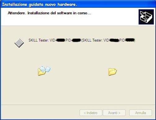
22 Connect the DB-25M connector (25-way male) to the tester and the EOBD socket to the vehicle: you can now switch on the tester (ref. Ch. 2.1 Switching on and off) and perform vehicle diagnosis. TC8-8/B Connect the DB-25M connector (25-way male) to the tester and the EOBD socket to the vehicle: you can now switch on the tester (ref. Ch. 2.1 Switching on and off) and perform vehicle diagnosis. TC8-3 Connect the DB-25M connector (25-way male) to the tester, connect the 2-way male connector to the power supply socket and the ISO lines to the diagnosis connector of the ECU involved in the diagnosis. In case of errors refer to Chapter Installation of SKILL ORGANIZER suite 1. Insert the CD provided with the Skill Tester ST05 into the PC s CD/DVD reader 2. Follow the steps of the guided installation through to the end (ref. Figure 14 (end of SKILL ORGANIZER installation)) Page 15 / 60
 the new peripheral device detected notification will appear and the guided hardware installation procedure will")
23 Figure 14 (end of SKILL ORGANIZER installation) 3. Switch on the Skill Tester ST05 using the AC/DC power supply unit and connect the tester to the PC using the USB cable 4. In the task bar (on the bottom right of the PC screen, where the Windows clock is) the new peripheral device detected notification will appear and the guided hardware installation procedure will start. Figure 15 (detection of new hardware) Page 16 / 60

 key.")
24 5. Follow the instructions in the guided hardware installation procedure, selecting the items shown by the green dots in the figures and pressing the NEXT ( AVANTI ) key. Page 17 / 60

25 Page 18 / 60

26 Figure 16 (hardware installation steps) At the end (software correctly installed and tester configured) you can proceed with the subsequent steps for updating and downloading data. In case of errors refer to Chapter Updating the Skill Tester ST05 software To update the diagnosis software on the tester two operational procedures can be followed: via the specially configured CF or via USB (using the SKILL ORGANIZER suite). Follow the procedure described below to set the tester to update mode: Page 19 / 60
27 Switch on the Skill Tester ST05 using the AC/DC power supply unit. From the MAIN MENU select the item UPDATE TESTER/COMMUNICATION. Figure 17 (MAIN MENU) At this stage follow the instructions according to the type of update (using the SUITE on the PC or the CF memory card). In case of errors refer to Chapter Tester software updating: SKILL ORGANIZER TESTER 1. Select the item UPDATE TESTER/COMMUNICATION Figure 18 (UPDATE TESTER/COMMUNICATION menu) Page 20 / 60
28 The following window will appear: Figure 19 (WAITING FOR PC) 2. Connect the tester to the PC using the USB cable. PC 1. Run the SKILL ORGANIZER application 2. Press the Update Skill Tester key 3. Select the file with the extension.update that you want to install 4. Press the OPEN ( APRI ) key and wait until the end of the automatic procedure. At the end the correct installation information message will appear and the tester will automatically restart. In case of errors refer to Chapter 6. Page 21 / 60
29 2.6.2 Tester software updating: CF memory card From the MAIN MENU select the item AUTOMATIC UPDATE WITH CARD and follow the instructions. Refer to Ch Updating with COMPACT FLASH. In case of errors refer to Chapter Downloading data from tester to PC Having saved the data on the tester (ref. Ch. 4.5 ACQUISITION ENVIRONMENT) you can download the saved data to the PC using the SKILL ORGANIZER suite. Run the SKILL ORGANIZER application using the special icon. From the Recorded/Freeze Management menu you will enter the environment shown in Figure 20 (Recorded/Freeze Management) Page 22 / 60
 Press the Select ALL key to select all of the acquisitions on the tester Press the Deselect ALL key to deselect all of the acquisitions on the tester Press")
30 Figure 20 (Recorded/Freeze Management) The list on the left List Data Skill contains the acquisitions present on the tester The list on the right List Data PC contains the acquisitions previously downloaded (therefore present on the PC) Press the Select ALL key to select all of the acquisitions on the tester Press the Deselect ALL key to deselect all of the acquisitions on the tester Press the >> key to copy the acquisitions selected from the tester to the PC Press the Erase key to erase the selected acquisitions Press the View key to view the selected acquisition Press the Exit key to exit the environment In case of errors refer to Chapter 6. Page 23 / 60
. When switched on (ref. Ch. 2.1 Switching on and off), the Base Software is loaded, which carries out an internal self-diagnosis and checks the vehicle configuration files contained in the tester.")
31 3. Operation MAIN MENU The software developed for the Skill Tester ST05 contains all of the vehicle diagnosis functions, the USB serial communication protocols for connection with the PC and the updating functions (ref. Ch. 2.6 Updating the Skill Tester ST05 software). When switched on (ref. Ch. 2.1 Switching on and off), the Base Software is loaded, which carries out an internal self-diagnosis and checks the vehicle configuration files contained in the tester. At the end of this check it will be possible to interact with the tester using the items in the menu shown in Figure 17 (MAIN MENU). You can restart the tester at any time using the start button (ref. Ch. 2.1 Switching on and off). Page 24 / 60
32 3.1 DIAGNOSIS MENU Select "DIAGNOSIS" and press ENTER to enter the menu which enables the user to select which car or program to run, for diagnosis execution. Depending on how many and which programs have been downloaded, the screen is as shown in fig. 22 NOTE: the number of MANUFACTURERS, MODELS AND SYSTEMS depend on the level of tester updating (ref. Ch 2.6 Updating the Skill Tester ST05 software). (Figure 21 (DIAGNOSIS, step 1)). Figure 21 (DIAGNOSIS, step 1) NOTE: The SCANTOOL environment does not contain any car to test but it is a general purpose environment for diagnosis on powertrain OBD ECU s. Page 25 / 60


33 To load a program into the memory and run it, select it (UP and DOWN keys) and press ENTER. The screen shown in fig. 23 appears and the selected software is run.. Figure 22 (DIAGNOSIS, step 2) This list shows the car models present on the tester: select the car required and press the ENTER key to confirm. The menu in fig. 24 will appear. Figure 23 (DIAGNOSIS, step 3) Page 26 / 60
34 The car specific executable systems will be displayed: select the ECU and press the ENTER key to confirm, then follow the instructions on the tester. 3.2 UPDATE TESTER/COMMUNICATION MENU Select the UPDATE TESTER/COMMUNICATION item from the MAIN MENU and press the ENTER key to access the items for updating the software on the tester. NOTE: as well as the basic application (internal management) the software also contains all the packages for the individual ECUs USB communication update Select "USB COMMUNICATION" to enter the Update menu. (Fig.25) The Skill Tester will automatically be set up for USB-computer communication Figure 24 (UPDATE) Page 27 / 60
35 Select "UPDATE TESTER " to enter the data management mode which requires the PC diagnosis suite (Skill Organizer) (fig ). At any time, press ESC to return to the main menu. Once on the PC Link menu, you can run the Update option; For all updating operations refer to Ch. 2.6 Updating the Skill Tester ST05 software. NOTE: in this case the software deletes any previously downloaded diagnosis program to avoid problems with the previously downloaded program release (correct execution is confirmed by a long BEEP). In case of errors refer to chapter 6. Error display Page 28 / 60
. Select the AUTOMATIC UPDATE WITH CARD item from the menu (Figure 25 (AUTOMATIC UPDATE WITH CARD menu)): the tester will automatically start the update.")
36 3.2.2 Updating with COMPACT FLASH CAUTION: before selecting the relevant item in the menu, make sure that the memory card (CF) containing the updates is correctly inserted in the special slot (ref. Ch. 1.5 Bottom view). Select the AUTOMATIC UPDATE WITH CARD item from the menu (Figure 25 (AUTOMATIC UPDATE WITH CARD menu)): the tester will automatically start the update. At the end of installation the tester restarts automatically and it will be possible to use the new functions installed. Figure 25 (AUTOMATIC UPDATE WITH CARD menu) Figure 26 (UPDATING SYSTEM ) In case of errors refer to chapter 6. Error display Page 29 / 60

37 3.3 SETUP TESTER MENU This Section allows the tester configuration to be changed. Any choice is only validated by pressing the ENTER key NOTE: the change will be set until a new set-up request by the user. Figure 27 (TESTER SET-UP menu) Page 30 / 60
38 3.3.1 BUZZER MENU Select the "BUZZER" option and press OK to enter the menu which sets the buzzer options (beep/no beep when the keys are pressed). The screen is as shown in fig. 28. Figure 28 (BUZZER menu) To activate/deactivate beeping when the keys are pressed, select the option you require (with UP and DOWN keys) and press OK. The setting is stored and retained even when the Tester is switched off and on again. Page 31 / 60
39 3.3.2 CONTRAST MENU Highlight the " CONTRAST" option and press OK to enter the contrast management menu display. The screen is as shown in fig. 29 Figure 29 (CONTRAST menu) Set the contrast level by selecting Contrast Increase or Contrast Decrease and pressing OK. The change takes effect immediately and you can confirm the setting by selecting Contrast Store and pressing OK; to exit without saving and return to the previous setting, just press ESC. Stored settings will be retained even when the Tester is switched off and on again SET LANGUAGE MENU Under development Select "SET LANGUAGE" and press OK to enter the menu which sets the language in which the screens are displayed. To set the display language, select the language required and press ENTER. The setting is stored and retained even when the Tester is switched off and on again. Page 32 / 60


40 3.4 INFORMATION MENU This section shows the information regarding the tester Software and hardware release. It is strongly recommended to use this information when reporting any HW or SW problem. Figure 30 (INFORMATION menu) Page 33 / 60
41 4. DIAGNOSIS Environment 4.1 FAULTS Environment The Faults environment downloads and displays the operating errors stored on the ECU. All possible errors are divided into pages. A circle to the right of an error in the column at the bottom indicates a current error. If many errors are present, use UP and DOWN or TAB to select pages and ESC to return to the main menu. (ref. Ch. 1.3 The splash-proof keypad). If no errors are displayed then no error has occurred or is present at the present time. Page 34 / 60
42 Figure 31 (NO ERROR) When errors are present you can select the highlighted fault using ENTER key. It displays the selected error with detailed information available. (error type, environment conditions, etc.) Note: The information depend on the car system NOTE: refer to the technical documentation related to the vehicle model for test and repair procedures! 4.2 ERASE FAULTS ENVIRONMENT Following confirmation the selection of this environment, the tester will proceed with erasing the errors on the ECU selected: follow the guided instructions to complete the procedure. Page 35 / 60
43 4.3 PARAMETERS ENVIRONMENT The PARAMETERS environment allows you to dynamically display (in real time) the parameters that the ECU uses to manage its system. Each parameter is associated with its own Unit of Measurement (in brackets ( ) ) and, on the right-hand side of the screen, the value sent back by the ECU. As an indication, in the top part of the screen, we have the name of the menu ECU PARAMETER LIST, the progressive number of the selected parameter and the total number of parameters. Page 36 / 60
44 Use the UP and DOWN keys to scroll through one parameter at a time, the TAB key to scroll through the pages, the ENTER key to display the details of the selected parameter and the ESC key to exit the menu. In case of loss of diagnostics communication refer to Chapter 6. By default the tester periodically tries to re-establish the connection: if the connection is restored the menu for the selected ECU will be shown. 4.4 ACTIVATION ENVIRONMENT The Activation environment allows the user to actuate the transducers controlled by the ECU. Within the Activation environment is a submenu with the various available actuations. Select the option required in the usual way (UP/DOWN to select, ENTER to confirm, ESC to return to the previous menu). After selecting a given actuation, the user is guided through the available procedures by a series of menus (example: Start Engine), and is asked to confirm commands sent to the ECU (example: Delete Errors). Finally, the user sends the diagnostics command to the ECU and the message RUNNING DIAGNOSIS is displayed. The user can interrupt the diagnosis by pressing ESC, or continue until the ECU terminates the procedure, either correctly or because an Page 37 / 60

45 actuation error occurs (a message appears to indicate which of these is the case). All diagnostic programs have similar interfaces to the one described above. 4.5 ACQUISITION ENVIRONMENT The Acquisition environment allows the user to select any parameter controlled by the ECU and record data on files. These data files are stored on the disk tester memory to be used later in off-line mode. Using the SKILL ORGANIZER, they will be downloaded onto the PC for analysis and printing. Within the Acquisition environment there is a submenu with various parameters available. Select the option required in the usual way (UP/DOWN to select, ENTER to confirm, ESC to return to the previous menu). Page 38 / 60
46 In order to save the files on the tester a vehicle serial number is required, and it will be used to name files connected to other information (timestamp). Figure 32 (ACQUISITION) Parameter Selection/Modify This allows you to select the parameters that you want to store from the list available: highlight a parameter using the UP and DOWN keys and press the ENTER key to mark it (an asterisk * will appear to the left of the parameter). Page 39 / 60
. 4.5.")

47 Figure 33 (No parameters Selected) Figure 34 (Parameters selected) To remove the flag press the ENTER key again (the asterisk * to the left of the parameter will disappear) Parameter Config Load This allows you to load a configuration (list of selected parameters) that has been saved previously. The configurations present on the tester will be listed: highlight the configuration required and press the ENTER key to confirm it. Page 40 / 60
 Figurea 36 (Parameters configuration list) 4.5.")
48 Figure 35 (saved configuration list) Figurea 36 (Parameters configuration list) Parameter Config Save It allows you to save a selected parameter list configuration. Page 41 / 60
 By selecting this menu item the tester will start the log (saving data to physical memory) of the selected parameters. 4.5.")
49 Figure 37 (storage confirmation) If no parameter has been selected this error message will be displayed START Recording Figure 38 (Storage error) By selecting this menu item the tester will start the log (saving data to physical memory) of the selected parameters START Watcher By selecting this menu item the tester will start the trace (screen display) of the selected parameters. Page 42 / 60
50 4.6 INFORMATION ENVIRONMENT This allows you to display information regarding the selected ECU (manufacturers identifiers). immagine Figure 39 Page 43 / 60
51 5. Diagnostic example This chapter describes the operation of a generic diagnosis program, since all diagnosis programs follow the broad outline of the procedure described below. When it starts running, the diagnosis program displays the Skill Tester logo. Following the DIAGNOSIS MENU instructions, we can identify the car model and the system to test. Press any key to display a screen which gives the name of the program and a set of data downloaded to check the ECU (assuming it to be connected, switched on and operating). This screen is displayed for a few seconds, unless the user presses a key. On our example we select a FERRARI 360 MODENA MOTRONIC. Once selected follow the tester s instructions. 1. Select the diagnostic ISO line required. NOTE: The ISO-1 line is considered as the default line (ref. Ch Tester-ISO Cable [TC8-3]) Figure 40 (ISO identification) Page 44 / 60
52 To use the 2 ISO line press ESC key and the following menu will appear:. Figure 41 (ISO 1 / 2) Having selected the ISO line, proceed with the following steps. 2. Insert the VSN (Vehicle Serial Number: Chassis Number or V.I.N.). Inserting this number is useful for the diagnostics session but not indispensable (press the ENTER key to avoid inserting any data): inserting of this data is necessary to perform parameter acquisition (the name of the acquisition file is given by this information). Figure 42 (VEHICLE SERIAL NUMBER) Page 45 / 60
53 3. ECU identification and initialisation In this step the tester will identify the ECU selected (in our case MOTRONIC): in the case of double ECU the menu below will appear. Select the ECU required and press the ENTER key. Figure 43 (ECU LH / RH) The tester will now start the diagnostics initialisation procedure. Figure 44 (TURN KEY ON) Page 46 / 60
 will appear.")
54 Figure 45 (INIT ECU) Figure 46 (INIT OK) Once the ECU has correctly initialised the window in Figure 47 (LOADING ) will appear. Figure 47 (LOADING ) Page 47 / 60
55 In case of errors refer to Chapter 6. Once the module for the selected ECU has been loaded you can proceed with the diagnostic analysis by selecting the appropriate item from the menu. Page 48 / 60
56 6. Error display 6.1 Compact Flash In case of errors (Compact Flash card not correctly inserted or does not contain the updating software) the following error window will appear: Figure 48 (CARD NOT FOUND) Insert the memory card in the correct slot and check that its contents are reliable and correctly configured. 6.2 No ECU initialisation or loss of diagnostics connection Any attempt to connect the tester to an ECU on the vehicle is always indicated by the following message window. Page 49 / 60
57 If there is no communication from the ECU or it is lost during a connection one of the following possible error windows will appear. Figure 49 (ECU TIMEOUT) Figure 50 (INIT KO) Page 50 / 60
58 Check that the connectors are correctly engaged Check that the vehicle conditions are correct (key in ON position, battery voltage OK, etc ) Check for any malfunctions of the vehicle s electric system (circuit open on diagnostic line, ECU not powered, etc ) Try to reactivate the communication by pressing the ENTER key Page 51 / 60
59 Index of Figures Figure 1 (menu ECU)... 2 Figure 2 (keypad)... 3 Figure 3 (top view)... 5 Figure 4 (bottom view)... 6 Figure 5 (rear view)... 7 Figure 6 (AC/DC power supply)... 8 Figure 7 (battery adapter)... 9 Figure 8 (Lighter adapter)... 9 Figure 9 (skill organizer) Figure 10 (EOBD standard) Figure 11 (EOBD Ferrari 360) Figure 12 (tester-iso) Figure 13 (tester boot window) Figure 14 (end of SKILL ORGANIZER installation) Figure 15 (detection of new hardware) Figure 16 (hardware installation steps) Figure 17 (MAIN MENU) Figure 18 (UPDATE TESTER/COMMUNICATION menu) Figure 19 (WAITING FOR PC) Figure 20 (Recorded/Freeze Management) Figure 21 (DIAGNOSIS, step 1) Figure 22 (DIAGNOSIS, step 2) Figure 23 (DIAGNOSIS, step 3) Figure 24 (UPDATE) Figure 25 (AUTOMATIC UPDATE WITH CARD menu) Figure 26 (UPDATING SYSTEM ) Figure 27 (TESTER SET-UP menu) Figure 28 (BUZZER menu) Figure 29 (CONTRAST menu) Figure 30 (INFORMATION menu) Figure 31 (NO ERROR) Figure 32 (ACQUISITION) Figure 33 (No parameters Selected) Figure 34 (Parameters selected) Figure 35 (saved configuration list) Figurea 36 (Parameters configuration list) Page 52 / 60
60 Figure 37 (storage confirmation) Figure 38 (Storage error) Figure Figure 40 (ISO identification) Figure 41 (ISO 1 / 2) Figure 42 (VEHICLE SERIAL NUMBER) Figure 43 (ECU LH / RH) Figure 44 (TURN KEY ON) Figure 45 (INIT ECU) Figure 46 (INIT OK) Figure 47 (LOADING ) Figure 48 (CARD NOT FOUND) Figure 49 (ECU TIMEOUT) Figure 50 (INIT KO) Page 53 / 60
SD3 DIAGNOSTICS SYSTEM USER MANUAL
 SD3 DIAGNOSTICS SYSTEM USER MANUAL Contents PRECAUTIONS AND SAFETY MEASURES... 4 Dataplate and warranty... 5 Warranty... 5 1. General information... 6 1.1 Minimum system requirements... 7 1.2 Suitcase
Instructions Manual. Page 1. BRT-12 Battery Replacement Tool
 Instructions Manual Page 1 Contents INTRODUCTION... 3 Safety Information... 3 Product Details:... 3 DISPLAY AND KEYPAD... 4 USER INTERFACE... 5 FIRST TIME USE... 6 OPTIONS MENU... 7 Main Menu screen...
General Notice Introduction Functional Description Product Troubleshooting Driver Setup...
 Table of Contents General Notice... 1 Introduction... 2 Functional Description... 4 Product Troubleshooting... 7 Driver Setup... 8 Firmware Update... 10 Warranty and Service... 12 General Notice The Bluetooth
99 Washington Street Melrose, MA Phone Toll Free Visit us at
 99 Washington Street Melrose, MA 02176 Phone 781-665-1400 Toll Free 1-800-517-8431 Visit us at www.testequipmentdepot.com Table of Contents 1. General Safety Requirements... 1 2. Safety Terms and Symbols...
Table of contents. Owner's Manual
 Table of contents 1 Owner's Manual Introduction is designed to program Dorman MULTi-FIT TPMS Sensors. Sensor Cradle LCD Display Indicators Keypad USB Connector Keypad Functions Keypad Summary Power On
Magnetek Material Handling IMPULSE LINK 4.1 Basic Instruction Manual
 Magnetek Material Handling IMPULSE LINK 4.1 Basic Instruction Manual February 2006 Part Number: 140-10350 Copyright 2006 Magnetek Material Handling 2005 MAGNETEK MATERIAL HANDLING All rights reserved.
FHD Driving Recorder E272S/S272W. Quick Start Guide
 FHD Driving Recorder E272S/S272W Quick Start Guide 400-8401-030 www.polaroidcarcam.com 1 Introduction 1.1 Package Contents The package contains the following items. In case there is any missing or damaged
Model P4017 Single Channel USB Oscilloscope. Quick Start Guide
 Model P4017 Single Channel USB Oscilloscope Quick Start Guide General Warranty BNC warrants that the product will be free from defects in materials and workmanship for 3 years from the date of purchase
NIDEC-SHIMPO INSTRUMENTS
 TTR Torque Tool Tester Operation Manual NIDEC-SHIMPO INSTRUMENTS 1) Overloading the transducer does not only damage the transducer but may break the transducer head and could result in injury! 2) Torque
X-431 Volkswagen Diagnosis. Table of Contents INTRODUCTION...1
 Table of Contents INTRODUCTION...1 FEATURES...1 Advanced...1 Open...1 Integrative...1 Flexible...1 HARDWARE CONFIGURATION...2 PORTS AND INDICATORS...3 PRINTER OPERATION...4 Mounting Paper...4 Printing
Mini DVR Module U S E R M A N U A L
 Mini DVR Module U S E R M A N U A L Contents 1. SAFETY PRECAUTIONS... 1 2. FEATURES... 2 3. PACKAGE CONTENT... 3 4. MINI DVR MODULE... 4 4.1 About the Mini DVR Module... 4 4.2 Mini DVR Module Layout...
Table of Contents. 1.Introduction... P.2. 2.Product Tour... P Operating Instructions... P Important Notes... P.10
 Table of Contents 1.Introduction... P.2 1-1.Basic Configuration 1-2.Product Features 2.Product Tour... P.3 2-1.Front Bezel 2-2.Top Bezel 2-3.Rear and Left Side 2-4.Slot Adaptor Usage 2-5.Battery Pack Box
Codian IP VCR IP VCR 2200 Series
 Codian IP VCR IP VCR 2200 Series Getting Started Codian IP VCR IP VCR 2200 Series Getting Started Copyright Codian 2006. All rights reserved. This Getting Started Guide may not be copied, photocopied,
UniPRO Gbis. User Guide issue 2. UniPRO Gbis Iss 1. User Guide
 UniPRO Gbis 123800 issue 2 UniPRO Gbis -0-123800 Iss 1 Copyright Notice The information contained in this document is the property of IDEAL INDUSTRIES Ltd. and is supplied without liability for errors
Table of Contents. 3.1 Front/Rear Panel and User Interface Front Panel Rear Panel User Interface...
 General Warranty OWON warrants that the product will be free from defects in materials and workmanship for a period of 2 years (1 year for accessories) from the date of purchase of the product by the original
Multi-Loader. User manual 06/ BBV48778
 Multi-Loader User manual 06/2009 BBV48778 www.schneider-electric.com Contents Important information 4 Before you begin 5 Documentation structure 6 Setup procedure 7 Introduction 8 Receipt of the Multi-Loader
Frequency Analysis Option (FAO) Manual. Table of Contents
 Manual. Table of Contents") Table of Contents 1. Introduction... 2 2. Installing the FAO Option... 2 3. Connecting to a Power Circuit... 3 4. Setting Up the Data Setup (PS4500 only)... 5 5. Capturing High Frequency Data... 6 6. Getting
Table of Contents 1. Introduction... 2 2. Installing the FAO Option... 2 3. Connecting to a Power Circuit... 3 4. Setting Up the Data Setup (PS4500 only)... 5 5. Capturing High Frequency Data... 6 6. Getting
Note: The following screenshots may not match the texts shown on the screen of your cars.
 MMI update programming for vehicles equipped with MMI High (MMI2G), e.g. A8 (4E), A6 (4F), Q7 (4L), A5 (8T) and A4 (8K) via the on-board CD drive with feedback documentation via Software Versions Management
TABLE OF CONTENTS TABLE OF CONTENTS... 1 MANUAL REVISION HISTORY... 2 IMPORTANT SAFETY NOTICE...
 TABLE OF CONTENTS TABLE OF CONTENTS... 1 MANUAL REVISION HISTORY... 2 IMPORTANT SAFETY NOTICE... 3 1.0 General Information... 5 1.1 System Components... 5 1.2 Specifications... 5 1.2.1 Torque Ranges...
NISSAN ECU FLASH REPROGRAMMER FOR WINDOWS (Ver. 1.00) INSTRUCTION MANUAL
 INSTRUCTION MANUAL") NISSAN ECU FLASH REPROGRAMMER FOR WINDOWS (Ver. 1.00) INSTRUCTION MANUAL !! NOTE and CAUTION!! Thank you for purchasing the TECHTOM Flash Reprogrammer. Please read and follow the instructions carefully
NISSAN ECU FLASH REPROGRAMMER FOR WINDOWS (Ver. 1.00) INSTRUCTION MANUAL !! NOTE and CAUTION!! Thank you for purchasing the TECHTOM Flash Reprogrammer. Please read and follow the instructions carefully
IDEAL INDUSTRIES INC. TECHNICAL MANUAL MODEL:
 IDEAL INDUSTRIES INC. TECHNICAL MANUAL MODEL: 61-795 The Service Information provides the following: Precautions and safety information Specifications Performance test procedure Calibration and calibration
Economy Single Channel Output DC Power Supply
 Economy Single Channel Output DC Power Supply User Manual www.owon.com.cn Feb. 2019 edition V1.1.0 Copyright LILLIPUT Company. All rights reserved. The LILLIPUT's products are under the protection of the
8806 Series. 15 Multi-functional Touch Panel PC. Quick Reference Guide
 8806 Series 15 Multi-functional Touch Panel PC Quick Reference Guide 1st Ed 10 July, 2009 8806 Contents 1. Getting Started...3 1.1 Safety Precautions...3 1.2 Packing List...3 1.3 System Specifications...4
EasyDiag User s Manual. Issued:
 Issued:2013-11-11 Precautions on operating vehicle s ECU Do not disconnect the vehicle inner consume when the ignition switch is on, so as to avoid the sensors or the ECU damage. Do not place the magnetic
EATON 5S 850/1200/1600
 www.eaton.com EATON 5S 850/1200/1600 Installation and user manual Packaging EATON 5S 1 2 3 5 Caution! l Before installing the Eaton 5S, read the booklet 3 containing the safety instructions to be respected.
iq DIGITAL PICTURE FRAME iq Digital Picture Frame DPF701SB USER GUIDE
 iq Digital Picture Frame DPF701SB USER GUIDE 1 Table of Contents Important Safety Precautions... 3 Cleaning the LCD Screen... 3 Cleaning the Digital Picture Frame... 3 Introduction... 4 What s in the Box...
VDI Pro Voltage & Dry Contact Interface Installation and programming Guide MODEL VDI MK2
 VDI Pro Voltage & Dry Contact Interface Installation and programming Guide MODEL VDI MK2 1 of 18 PREFACE Important Installation Information It is the purchasers responsibility to determine the suitability
Emerson Network Power provides customers with technical support. Users may contact the nearest Emerson local sales office or service center.
 Liebert PSA iton User Manual Version: V2.8 Revision date: November 14, 2005 Emerson Network Power provides customers with technical support. Users may contact the nearest Emerson local sales office or
Frequency Analysis Option (FAO) Manual. Table of Contents
 Manual. Table of Contents") Table of Contents 1. Introduction... 2 2. Installing the FAO Option... 2 3. Connecting to a Power Circuit... 3 4. Capturing High Frequency Data... 4 5. Getting the Frequency Analysis Data out of PowerSight...
Table of Contents 1. Introduction... 2 2. Installing the FAO Option... 2 3. Connecting to a Power Circuit... 3 4. Capturing High Frequency Data... 4 5. Getting the Frequency Analysis Data out of PowerSight...
AerMonitor AM Aer Monitor User's Manual. Version-0.1
 AerMonitor AM-1015 Aer Monitor User's Manual Version-0.1 AerMonitor AM-1015 Copyright Notice This document is copyrighted, 2013. All rights are reserved. Firich Enterprise Co., Ltd reserves the right to
This manual describes the installation, setup and operation of this equipment in details.
 About This Manual This manual describes the installation, setup and operation of this equipment in details. Please read it carefully to make sure you can operate the multiplexer correctly. Important Avoid
CALOG CALOG - LC DISPLAY. Loadcell Display. English Users Manual. Rev. 1.10
 CALOG C A L I B R AT O R S CALOG - LC DISPLAY Loadcell Display English Users Manual Rev. 1.10 Table of Contents! Contents! 1.0 Introduction...2! 2.0 Getting Started...2! 2.1 Keypad...2! 2.2 Display...2!
CyberView User Manual
 CyberView User Manual RKP215-801 RKP217-801 RKP215-1601 RKP217-1601 2U Rackmount LCD monitor Keyboard drawer with KVM switch Version 2.0 20 March 2004 Table of Contents 1.0 General... 3 1.1 Unit Introduction...
EasyDiag Series. User s Manual (V ) Issued Date:
 Issued Date:") EasyDiag Series User s Manual (V1.00.001) Issued Date: 2014-08-15 Note: This user s manual applies to EasyDiag Series (EasyDiag and EasyDiag Plus) and is subject to change without prior written notice.
EasyDiag Series User s Manual (V1.00.001) Issued Date: 2014-08-15 Note: This user s manual applies to EasyDiag Series (EasyDiag and EasyDiag Plus) and is subject to change without prior written notice.
UC-7400 Plus Hardware User s Manual
 Fourth Edition, April 2009 www.moxa.com/product 2009 Moxa Inc. All rights reserved. Reproduction without permission is prohibited. The hardware described in this manual is furnished under a license agreement
TIME SERVER NETSILON. Quick start.
 TIME SERVER NETSILON Quick start This document refers to the following products: 907,900 NETSILON 7 (100-240 VAC) 907,901 NETSILON 7 (18-36 VDC) 907,902 NETSILON 7 (100-240 VAC + 18-36 VDC) www.bodet-time.com
Powergate³ User. Instruction manual and user s guide
 Powergate³ User Instruction manual and user s guide This manual explains features and provides basic information about how to set up and operate the Powergate³ User, including instructions on how to install
ThinkCentre Hardware Installation and Replacement Guide. Machine Types 6062, 6065, 6071, 6076, 6089, 7103, 9011, 9014, 9071, 9089, 9162, 9182, 9303
 ThinkCentre Hardware Installation and Replacement Guide Machine Types 6062, 6065, 6071, 6076, 6089, 7103, 9011, 9014, 9071, 9089, 9162, 9182, 9303 ThinkCentre Hardware Installation and Replacement Guide
Abrites Commander for BMW vehicles
 Abritus 72 Ltd Date: 06-July-2011 Abrites Commander for BMW vehicles User Manual Beta Version Version: 3.0 issued by: Abritus 72 Ltd ABRITES COMMANDER FOR BMW V8.0 Document number 1/20100512 Date: 06-July-2011
ISTA User instructions for the BMW Online Service System for BMW Service and MINI Service (OSS)
") ISTA User instructions for the BMW Online Service System for BMW Service and MINI Service (OSS) Release 1.0 Technical documentation and diagnosis BMW Group Page 2 Contents 1 Introduction......... 4 1.1
ISTA User instructions for the BMW Online Service System for BMW Service and MINI Service (OSS) Release 1.0 Technical documentation and diagnosis BMW Group Page 2 Contents 1 Introduction......... 4 1.1
Instruction Manual. 9 Dual Screen Portable DVD Player - BPDVD99
 Instruction Manual 9 Dual Screen Portable DVD Player - BPDVD99 CONTENTS General Safety 4 Product Overview 7 Remote Control 9 Getting Started 10 Setup 11 Troubleshooting 12 Specifications 12 Support 16
GCI-5K INSTALLATION AND OPERATOR S MANUAL
 GCI-5K INSTALLATION AND OPERATOR S MANUAL Grid-tied inverter for wind Ningbo Ginlong Technologies 1 INTRODUCTION 2 SAFETY GUIDELINES AND WARNINGS 3 INSTALLATION 3.1 Selecting a location for the inverter
Instruction Manual. 14 Portable DVD Player - BPDVD14
 Instruction Manual 14 Portable DVD Player - BPDVD14 CONTENTS General Safety 4 Product Overview 7 Remote Control 9 Getting Started 10 Setup 11 Troubleshooting 13 Specifications 13 Support 16 GENERAL SAFETY
SLIMLINE DASH CAM Audio & Video Recorder
 SLIMLINE DASH CAM Audio & Video Recorder 1 EK142CAM INSTRUCTION MANUAL PLEASE READ ALL INSTRUCTIONS CAREFULLY AND RETAIN FOR FUTURE USE Getting Started Remove the Car Digital Video Recorder from the box.
Rack Mount LCD KVM Assembly. Installer/User Guide
 Rack Mount LCD KVM Assembly Installer/User Guide Rack Mount LCD KVM Assembly Installer/User Guide Avocent, the Avocent logo and The Power of Being There are registered trademarks of Avocent Corporation
Model: KB1700. Programmable Keypad. 17 Programmable Keys USER MANUAL
 Model: KB1700 Programmable Keypad 17 Programmable Keys USER MANUAL NOTICE The manufacturer of the POS programmable keypad makes no representations or warranties, either expressed or implied, by or with
User s Manual June 2007
 TM USER S MANUAL User s Manual June 2007 Trademarks Snap-on, Sun, SOLUS, and Scanner are trademarks of Snap-on Incorporated, registered in the United States and other countries. All other marks are trademarks
SDP:01. Scania Diagnos & Programmer 3. en-gb. User instructions Applies from SDP Issue 19. Scania CV AB 2014, Sweden
 SDP:01 Issue 19 en-gb Scania Diagnos & Programmer 3 User instructions Applies from SDP3 2.18 Scania CV AB 2014, Sweden Introduction... 3 General... 3 System requirements and ancillary equipment... 4 System
Manual. Dimmer DMD-12-2
 Manual Dimmer DMD-12-2 Table of contents 1. Safety instructions... 3 1.1. For safe and efficient operation... 3 2. Overview... 5 2.1. Front view... 5 2.2. Rear view... 6 2.3. Termination... 6 3. Operating
Trademark. Cadex C5100 BatteryStore v1.5 User Guide
 v1.5 Trademark C5100 BatteryStore is a trademark of Cadex Electronics Inc. All other trademarks or registered trademarks mentioned herein are the property of their respective owners. Copyright Notice Copyright
Model 7705 Control Module
 www.keithley.com Model 7705 Control Module User s Guide PA-696 Rev. D / October 2006 A G R E A T E R M E A S U R E O F C O N F I D E N C E Safety Precautions The following safety precautions should be
Introduction Product Overview Product Features:
 USER GUIDE HDDVR186 Introduction Thank you for purchasing the Gator Digital Video Recorder 186. This product is designed to provide high quality recording of your trips for security and evidence in the
RVU - Update Programming For Catalytic Converter System (IC)
") 26 07 01 May 11, 2007 2010066/3 Supersedes Technical Service Bulletin Group 26 number 05-03 dated July 20, 2005 due to addition of Saga warranty data, change in VIN range, and reformatting RVU - Update
26 07 01 May 11, 2007 2010066/3 Supersedes Technical Service Bulletin Group 26 number 05-03 dated July 20, 2005 due to addition of Saga warranty data, change in VIN range, and reformatting RVU - Update
OVERVIEW: This bulletin involves flash reprogramming the audio amplifier with revised software ( AN).
.") NUMBER: 08-033-04 GROUP: Electrical DATE: October 15, 2004 This bulletin is supplied as technical information only and is not an authorization for repair. No part of this publication may be reproduced,
NUMBER: 08-033-04 GROUP: Electrical DATE: October 15, 2004 This bulletin is supplied as technical information only and is not an authorization for repair. No part of this publication may be reproduced,
Voca safety instructions
 Voca Voca safety instructions 1. Read these instructions All the safety and operating instructions should be read before this product is operated. 2. Keep these instructions The safety and operating instructions
unit 0 introduction The following instructions should always be strictly followed:
 introduction Hw installation Sw installation Sw interface acceptance ECU diagnosis programming active diagnosis engine test electrical diagram guide to diagnosis eltracscope Bluetooth Device sw automatic
AEROTRAK PORTABLE AIRBORNE PARTICLE COUNTER MODEL 9310/9350/9510/9550/9500 QUICK START GUIDE
 AEROTRAK PORTABLE AIRBORNE PARTICLE COUNTER MODEL 9310/9350/9510/9550/9500 QUICK START GUIDE Thank you for purchasing a TSI AeroTrak Portable Airborne Particle Counter (particle counter). This guide will
Industrial Worksite Outdoor Rechargeable Bluetooth Speaker with FM radio and USB/SD Flash Drive PWPBT250 INSTRUCTION MANU
 Industrial Worksite Outdoor Rechargeable Bluetooth Speaker with FM radio and USB/SD Flash Drive PWPBT250 INSTRUCTION MANU IMPORTANT SAFETY INSTRUCTIONS: 1. Read the instructions. All uses guidelines must
Troubleshooter Quick Reference Guide
 Troubleshooter Quick Reference Guide March 2008 EAZ0025B29B Rev. C Trademarks Acknowledgement Snap-on, Scanner, and Fast-Track are trademarks of Snap-on Incorporated. All other marks are trademarks of
LevelOne. KVM-0115/KVM / 17-inch LCD KVM Rack Console. User Manual. Version
 LevelOne KVM-0115/KVM-0117 15 / 17-inch LCD KVM Rack Console User Manual Version 1.0-1305 1 SAFETY INSTRUCTIONS 1. Please read these safety instructions carefully. 2. Please keep this User Manual for later
12/2013. Installation Guide & User Manual
 12/2013 Installation Guide & User Manual ABOUT THIS MANUAL This manual has been written to help you understand all the functions and capabilities of the Yamaha Snowmobile Diagnostic Tool in order to gain
User Manual AIMB-C200. Economical Embedded Chassis for Mini-ITX Motherboard
 User Manual AIMB-C200 Economical Embedded Chassis for Mini-ITX Motherboard Copyright The documentation and the software included with this product are copyrighted 2010 by Advantech Co., Ltd. All rights
Deviser Part No.: TC500-DL Deviser Instruments, Inc. All rights reserved.
 TC500 Ethernet Cabling Certifier Operation Manual Version 1.13 Deviser Part No.: TC500-DL Deviser Instruments, Inc. All rights reserved. Warranty This instrument is guaranteed for a period of 2 years
VTRAK E-Class/J-Class Quick Start Guide
 VTRAK E-Class/J-Class Quick Start Guide Version.0 Firmware 3.9 008 Promise Technology, Inc. All Rights Reserved. VTrak Quick Start Guide About This Guide This Quick Start Guide shows you how to install
Owner s Manual Havis Docking Station For Getac F110 Rugged Tablet
 Owner s Manual Havis Docking Station For Getac F110 Rugged Tablet Related Products Havis offers a wide variety of accessory products specifically for use with the DS-GTC-210 Series Docking Station. For
Release Date: September 4, 2014
 MV1DU User s Guide Release Date: September 4, 2014 Use of the MV1DU Diagnostic System requires an active license agreement or MV-1 Dealer Agreement. For information on obtaining a license, please email
Service Technical Resources MUT-III. (Multi-Use Tester-III*) Quick Reference Guide
 Quick Reference Guide") Service Technical Resources MUT-III (Multi-Use Tester-III*) Quick Reference Guide *Cart not included May, 2003 INTENDED USAGE OF MUT-III MUT-II role after MUT-III Launch MUT-III is an essential special
Service Technical Resources MUT-III (Multi-Use Tester-III*) Quick Reference Guide *Cart not included May, 2003 INTENDED USAGE OF MUT-III MUT-II role after MUT-III Launch MUT-III is an essential special
CPU-02 Module (Model: JAPMC - CP2210)
") CPU Module for MP2200 Machine Controller CPU-02 Module (Model: JAPMC - CP2210) Guide for Connections and Operations 1.1 How to Connect the CPU-02 Module - - - - - - - - - - - - - - - - - - - 2 1.1.1 Connecting
CPU Module for MP2200 Machine Controller CPU-02 Module (Model: JAPMC - CP2210) Guide for Connections and Operations 1.1 How to Connect the CPU-02 Module - - - - - - - - - - - - - - - - - - - 2 1.1.1 Connecting
M.U.T.-III Owner s Manual
 MITSUBISHI MOTORS M.U.T.-III Owner s Manual Multi Use Tester < Ver. 7.0 > Heart-Beat Motors MITSUBISHI MOTORS M.U.T.-III Owner's Manual Foreword This manual explains M.U.T.-III: functions, operating procedures,
User Guide DMX TESTER
 User Guide DMX TESTER Document Release Aug. 2006 Revision A Warranty Leviton Manufacturing Co Inc. warrants this control console to be free of material and workmanship defects for a period of two years
LevelOne KVM User Manual. 17 Modularized KVM Console V
 LevelOne KVM-0217 17 Modularized KVM Console User Manual V1.0.0-0708 SAFETY INSTRUCTIONS 1. Please read these safety instructions carefully. 2. Please keep this User Manual for later reference. 3. Please
Software Guide Compaq Tablet PC TC1000 Series
 b Software Guide Compaq Tablet PC TC1000 Series Document Part Number: 280125-001 November 2002 This guide explains how to manage power and passwords; use the Q Menu and the Desktop Profile Manager, Setup,
SATA II HDD Canister KISS DA 435 Quick Reference Guide
 SATA II HDD Canister KISS DA 435 Quick Reference Guide If it s embedded, it s Kontron 1. Table of Contents SATA II HDD Canister KISS DA 435 1. Table of Contents 1. Table of Contents... 1 2. Important Information...
USER GUIDE. 3 Channel DC Current Datalogger Model SD900
 USER GUIDE 3 Channel DC Current Datalogger Model SD900 Table of Contents 1. INTRODUCTION 3 2. DESCRIPTIONS 4 3. OPERATION 5 Power 5 Connecting Current Cables 5 Datalogging 5 Time/Date/Sample Rate Check
INTRODUCTION SAFETY INSTRUCTION FEATURES
 INTRODUCTION Thank you for your purchasing our newest Caller ID phone with phonebook function. This manual is designed to familiarize you with this phone. To get the maximum use from your new phone, we
Disclaimer. Safety Precautions and Warnings. icarsoft English User s Manual
 2015-02-06 V1.00.00 Note: This manual applies to icarsoft 2nd generation serial products and CR Plus and is subject to change without prior written notice. In addition, all instructions and illustrations
EMC VNXe. Replacing a link control card in a 12-slot disk-array enclosure REV 02. July, 2015
 EMC VNXe Replacing a link control card in a 12-slot disk-array enclosure 302-000-216 REV 02 July, 2015 This document describes how to replace a link control card (LCC) in a 12-slot disk-array enclosure
GDS - Basic Operation. Ver
 GDS - Basic Operation Ver. 04. 06. 2010 Recovery Procedure GDS - Basic Operation Module: A 02-001-1 (p.01) Recovering the GDS Software WARNING When reinstallation procedure is performed, the contents of
Precautions. sure the diagnostic socket on your vehicle export 11V~36V voltage. HD The HD900 work in 11V~36V voltage, please make
 Declaration HD900 1. This manual is designed for the usage of HD900. No part of this manual can be reproduced, stored in a retrieval system or transmitted, in any form or by any means (electronic, mechanical,
HPE Intelligent Power Distribution Unit Installation Instructions
 HPE Intelligent Power Distribution Unit Installation Instructions Important safety information For important safety, environmental, and regulatory information, see Safety and Compliance Information for
HP LaserJet MFP Analog Fax Accessory 300. Supplemental Information
 HP LaserJet MFP Analog Fax Accessory 300 Supplemental Information HP LaserJet MFP Analog Fax Accessory 300 Supplemental Information Copyright Information 2005 Copyright Hewlett-Packard Development Company,
Universal AC Power Source + AC Power Analyzer
 User's Guide Universal AC Power Source + AC Power Analyzer Model 380820 Introduction Congratulations on your purchase of the Extech Model 380820. This Universal AC Power Source and AC Power Analyzer can
DVI EDID Reader / Writer
 DVI EDID Reader / Writer Model #: C-EDID-RW 2010 Avenview Inc. All rights reserved. The contents of this document are provided in connection with Avenview Inc. ( Avenview ) products. Avenview makes no
TABLE OF CONTENTS TABLE OF CONTENTS... 1 IMPORTANT SAFETY NOTICE...
 TABLE OF CONTENTS TABLE OF CONTENTS... 1 IMPORTANT SAFETY NOTICE... 2 1.0 General Information... 3 1.1 System Components... 3 1.2 Specifications... 3 1.2.1 Torque Ranges... 3 1.2.2 Electrical Specifications...
MC-12 Software Installation Instructions
 MC-12 DOCUMENTATION CONVENTIONS This document contains software installation instructions for the MC-12/MC-12 Balanced. Refer to the MC-12 User Guide for general safety, installation, and operating instructions.
IMPORTANT NOTICES... Inside Front Cover. Safety Information Introduction... 1
 IMPORTANT NOTICES 1 855 855 Contents IMPORTANT NOTICES... Inside Front Cover Safety Information... 5 1. Introduction... 1 1.1. Product Overview... 1 1.2. Component Descriptions... 1 1.2.1. MaxiDAS Scan
EXPRESS. Users Guide. Version 3.5
 EXPRESS Users Guide Version 3.5 Table of Contents 1 System Overview... 3 2 System Requirements... 3 3 Contents in ECMTUNE System Box... 3 4 Installation Information... 4 5 Registration Information... 7
AX3000 Platine Terminal Ethernet TCP/IP
 AX3000 Platine Terminal Ethernet TCP/IP Model 75E Installation Guide January 003 - Ref: I75EE0303-1 Model AX3000/M75E The reproduction of this material, in part or whole, is strictly prohibited. For additional
Temposonics Magnetostrictive Linear Position Sensors
 Temposonics Magnetostrictive Linear Position Sensors TempoLink Smart Assistant I AM V THE NEW GENERATION Table of contents 1. Introduction...3 2. Safety instructions...4 2.1 Intended use...4 2.2 Foreseeable
AK-C6A In Car Dash Camera. Instruction Manual Model Ref: MM347
 AK-C6A 20032017 In Car Dash Camera Instruction Manual Model Ref: MM347 Introduction Thank you for choosing this In Car Dash Camera. This product is manufactured to the highest standards of performance
Introduction to the Autologic Vehicle Diagnostic Tool
 Introduction to the Autologic Vehicle Diagnostic Tool User Instructions Version 4.0 Issued April 2012 For the latest version of this document see www.autologic.com Ltd has made every effort to make sure
Fujitsu Stylistic ST4000 Series TABLET DOCK USER S GUIDE
 Fujitsu Stylistic ST4000 Series TABLET DOCK USER S GUIDE DECLARATION OF CONFORMITY according to FCC Part 15 Responsible Party Name: Fujitsu PC Corporation Address: 5200 Patrick Henry Drive Santa Clara,
SAFETY PRECAUTIONS AND WARNINGS...
 Table of Contents 1. SAFETY PRECAUTIONS AND WARNINGS... 1 2. TOOL INFORMATION... 2 2.1 TOOL DESCRIPTION... 2 2.2 SPECIFICATIONS... 3 2.3 ACCESSORIES INCLUDED... 3 2.4 ICONS... 4 2.5 KEYBOARD... 4 2.6 BATTERY
Taurus Super-S3 LCM. Dual-Bay RAID Storage Enclosure for two 3.5-inch Serial ATA Hard Drives. User Manual March 31, 2014 v1.2
 Dual-Bay RAID Storage Enclosure for two 3.5-inch Serial ATA Hard Drives User Manual March 31, 2014 v1.2 www.inxtron.com EN Table of Contents Table of Contents 1 Introduction... 1 1.1 Technical Specifications...
User Manual - KVM Rear Kit Version
 dedicated KVM switch and rackmount screen technology User Manual - KVM Rear Kit Version for LCD Console Drawer PS/2 DB-15 KVM - 801 back Designed and manufactured by Austin Hughes 751 Legal Information
QUICK SETUP GUIDE PMC-1000, PMC-1001, PMM-1000, PMB PM Series Power Meter. Safety Information. Equipment Maintenance and Service.
 PM Series Power Meter QUICK SETUP GUIDE PMC-1000, PMC-1001, PMM-1000, PMB-1960 Safety Information DANGER! HAZARD OF ELECTRIC SHOCK, EXPLOSION, OR ARC FLASH Follow safe electrical work practices. See NFPA
User Manual. Programming & SCN-Coding of Emission Related Control Units with Pass-Thru Programming System SAEJ2534. Version 0.7.
 User Manual Programming & SCN-Coding of Emission Related Control Units with Pass-Thru Programming System SAEJ2534 Version 0.7. 1/28 Table of Content 1. General Introduction on Pass Thru SAEj2534 Compliant
ISTA User's Manual Release 2.x Technical Documentation and Diagnosis
 ISTA User's Manual Release 2.x Technical Documentation and Diagnosis BMW Group Page 2 Contents 1 Introduction...5 1.1 Explanation of the symbols used...5 1.2 Important security instructions...5 1.3 Chapter
General Warranty. For more details, please refer to the user manual, it can be downloaded at
 General Warranty OWON warrants that the product will be free from defects in materials and workmanship for a period of 1 year from the date of purchase of the product by the original purchaser from the
HP Notebook PCs - Keyboard and TouchPad or ClickPad Guided Troubleshooter
 HP Notebook PCs - Keyboard and TouchPad or ClickPad Guided Troubleshooter This document applies to HP notebook computers. The keyboard, TouchPad, or ClickPad on your laptop is not working as expected: