994 LASER QUICK GUIDE
|
|
|
- Dominick Foster
- 5 years ago
- Views:
Transcription


1 994 LASER Quick-Start Guide CONTENTS Machine set-up & password entry Jaw calibration Cut by code & decode How to replace the cutter & change the tracer Short form instructions Replacemente parts list IMPORTANT Please read the following instructions carefully as improper use can damage the machine and may avoid the warranty 994 LASER QUICK GUIDE Keyline S.p.A. 1

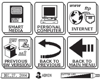
2 1. Initial Setup Cable Connection and Powering Machine Mobile users: you must use a pure sine wave inverter with 1100 watts (or greater) to power the machine or machine motor will not work properly. Do not install jaw until instructed on page 2 of this guide. 1. Attach the 9-pin connector cable to the LOWER port on the back of the console AND to the back of the machine. SECURE WITH ATTACHED SCREWS! 2. Attach power cord to back of machine and plug into a properly grounded outlet. 3. Make sure the ON/OFF switch above the power cord is to the ON position. 4. Rotate the Emergency Stop button towards the back of the machine until it releases outward. 5. The machine will now begin to start-up. This process takes a few seconds. Proceed with Password Entry. Powering Machine OFF 1. Select BACK TO MAIN MENU from any screen 2. Select: EXIT 3. Select: OFF 4. Screen will display NOW YOU CAN TURN OFF THE MACHINE. 5. Press the Emergency Stop Button to turn OFF the machine. 2 Keyline S.p.A. 994 LASER QUICK GUIDE


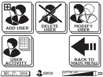
3 2. Password Entry Touch Screen: For best results use a non- metallic stylus such as a plastic tip end of a pen, tip of brush handle, etc. 1. Type in Master Password: Press: ENTER 2. Press: YES* 3. Your Laser 994 is now ready for use *If YES is selected the following should occur: The default password should be changed by the assigned Administrator for continued security of the Machine. If the password is not changed, anyone can access the secured screens using the default password. The new Master password should be documented and stored in a safe place in case the password is forgotten. The Master (Administrator) Password permits access to all screens. All other USER passwords will not have access to secure screens. At least one additional new password should be assigned for USERS other than the Administrator. To add additional USERS see page 36 in your machine manual. 994 LASER QUICK GUIDE Keyline S.p.A. 3
4 IMPORTANT COMPLETE JAW SETUP Before using the machine to cut any keys, please SETU P ALL TH E JAW S using the template (silver template with the key ring on one end) found in the black accessory case. Follow the directions on page 4 of this guide. This adjustment is necessary due to fluctuations and changes that have occurred during shipping. Failure to follow this procedure correctly may cause damage to the tracer, cutter, and/or jaw and may result in voiding any warranty. If you have any questions on these procedures, please contact Keyline USA Technical Support: Monday-Friday between 8am-5pm EST at: CUTTER LIFE & KEY MATERIAL Cutting steel keys is not recommended with the 994. Cutter life will be drastically reduced and/or cutter damage may occur. In addition, the 994 cannot cut or decode any type of plastic key. 4 Keyline S.p.A. 994 LASER QUICK GUIDE
.")
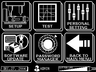
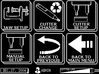
5 3. Jaw Setup Procedure 1. Select: Setup/Test 2. Select: Setup 3. Select: Jaw Setup 4. Select: Desired Jaw (use DOWN arrow to select other jaws). Press: Enter Install Jaw to far left of carriage until it stops. CLAMP TIGHT WITH RED JAW LEVER. 5. Insert the SILVER TEMPLATE (metal bar with key ring in accessory kit). Hold blank FLAT in jaw & press in and down while tightening. Press: YES to calibrate jaw 6. SETUP OK Record Setup numbers then do a second Jaw Setup (starting from Step 1). Compare the Setup numbers to first set. If they are within +/- 2 of original numbers, Jaw Setup is complete. Remove silver template. Press: OK (If not, run third Jaw Setup and compare 2nd & 3rd setup numbers.) 994 LASER QUICK GUIDE Keyline S.p.A. 5

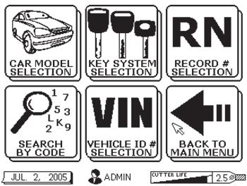
6 4. How to Cut by Code If Required, Enter Your Password 1. Select: Key Search 5. Verify key code is correct. Press: ENTER. 2. Select: Car Model Selection, then enter the Make, Model & Year when prompted. Press: ENTER. Note: If desired vehicle is not displayed in the Model selection, touch the down arrow to view additional vehicles with similar code series. 3. Select: Cut by Code when prompted 6. Key blank reference screen. Press: ENTER. 7. Follow screen prompts. Insert correct Jaw and clamp tight. Insert key blank Press in and down on blank while clamping. Press: YES. 4. Enter Desired Key Code Press: Enter 8. Follow onscreen prompts until cutting is complete. 6 Keyline S.p.A. 994 LASER QUICK GUIDE


7 5. How to Cut by DECode Decode Metal Keys Only! Do Not Decode Plastic Keys! 1. Select: Key Search 2. Select: Car Model Selection, 4. If desired Model is not displayed Touch: Down Arrow to view additional vehicles with similar codes. Select: Desired MODEL Press: ENTER 3. If desired Make is not displayed Touch: Down Arrow to view additional vehicles with similar codes. Select: Desired Make Press: ENTER 5. If desired Year is not displayed Touch: Down Arrow to view additional vehicles with similar codes. Select: Desired YEAR RANGE Press: ENTER 6. Select: CUT BY DECODE CONTINUE 994 LASER QUICK GUIDE Keyline S.p.A. 7


8 5. How to Cut by DECode 7. Insert Jaw and clamp tight. Insert ORIGINAL key blank- press down on blank while clamping jaw tight. Press: YES Decoding In Process 8. Verify Decoded Key. Make sure Key Code is displayed. Press: ENTER 10. Remove ORIGINAL key. Insert new key blank- press down On blank while clamping jaw tight. Press: YES 9. Key blank reference list is displayed. Press: ENTER 11. BRUSH OFF ALL CHIPS - Turn key over and press down on blank while clamping jaw tight. Press: YES 8 Keyline S.p.A. 994 LASER QUICK GUIDE


9 6. How to to Replace the Cutter Select: SETUP TEST Select: SETUP Select: CUTTER CHANGE 1. Insert RED rod through hole in top of machine 2. Rotate rod until it drops into position 3. Press down to lock onto cutter 4. Rotate until arrow on RED rod points left (9 o clock position) 5. Insert LONG T-wrench into black collar on left side of cutter guard 6. Loosen 3 turns. Leave wrench in place 7. Remove RED rod with cutter attached 8. DO NOT INSTALL NEW CUTTER AT THIS TIME!!! 9. Press: CONTINUE DO NOT INSTALL CUTTER Press CONTINUE 10. Insert new cutter on RED rod. Pressing in until It clicks 11. Insert RED rod with new cutter through hole in the top of the machine. 12. Rotate until cutter RESTS LIGHTLY on the SILVER DOT on the jaw 13. Tighten setscrew with the Long T-wrench 14. Remove T-wrench and RED rod. Press: YES Reset Cutter Counter? Press: YES (only if cutter is brand new) 994 LASER QUICK GUIDE Keyline S.p.A. 9
10 7. How to Change the Tracer 1 1. Use small 2.5mm T-wrench to loosen tracer setscrew. 2. Insert into hole in right side of shield. 3. Unscrew 1/2 turn. 4. Pull out tracer. 5. You may use pliers to remove tracer if it is bent or broken Install new tracer as far is it will go up - you cannot go too far. 2. Be sure flat side of tracer is to the right to allow the setscrew to seat properly. 3. Tighten setscrew. DO NOT OVER TIGHTEN! 4. SEE JAW SETUP INSTRUCTIONS ON PAGE Keyline S.p.A. 994 LASER QUICK GUIDE


11 Short Form Instructions For Technical Support call LASER QUICK GUIDE Keyline S.p.A. 11
12 Laser 994 Replacement Parts List Description Universal 2.5mm cutter Tracer High Security 1.5mm cutter Edge Cut Tracer Edge Cut Magnetic Tip Stop for use with F Jaw Plunger Tool Honda test blanks (5pk) Cutter setup blanks (5pk) Jaw calibration template Red A Jaw Gray B Jaw Green C Jaw Blue D Jaw Fan Filter Infiniti Adaptor Lexus 80K Adaptor Ducati/Aprilia/Guzzi Adaptor 3mm T-wrench (Long) 2.5mm T-wrench (Short) Automatic Vacuum Attachment Part Number B3320 B3310 B3403 B3404 B3405 B3315 B3353 B3319 B3354 B3311 B3312 B3313 B3314 B3326 B3352 B3379 AV08 B3316 B3317 B Keyline S.p.A. 994 LASER QUICK GUIDE
BD Laser User Guide * IMPORTANT * PLEASE READ THE FOLLOWING INSTRUCTIONS CAREFULLY AS IMPROPER USE MAY DAMAGE THE MACHINE AND VOID THE WARRANTY.
 BD Laser User Guide * IMPORTANT * PLEASE READ THE FOLLOWING INSTRUCTIONS CAREFULLY AS IMPROPER USE MAY DAMAGE THE MACHINE AND VOID THE WARRANTY. BD Laser arrives ready to use with jaws and cutters preinstalled.
* IMPORTANT * REGISTERING YOUR MACHINE
 * IMPORTANT * REGISTERING YOUR MACHINE Thank you for your purchase of the Keyline 994 Laser. Before continuing with machine setup and use, please complete the following; COMPLETE PRODUCT REGISTRATION FORM
Triax A/T QUICK START GUIDE
 Triax A/T QUICK GUIDE Please read all instructions carefully before operating your Triax A/T Key Machine. 1. Preparation A. First remove the Triax A/T machine from its cardboard box and pallet. The machine
Nov. 07, 2013 p. 5 - changed the B axis unit value to from Changed by Randy per Frank s request.
 Correction notes Nov. 07, 2013 p. 5 - changed the B axis unit value to 45.1389 from 40.0000. Changed by Randy per Frank s request. Jan. 22, 2018 p. 5 - changed the B axis unit value and corresponding picture
User Guide Instruction Manual
 User Guide Instruction Manual Please wear Safety Glasses at all times while operating this machine. DO NOT attempt to lubricate the machine. Clean only with a brush and or vacuum. Shield must be lowered
Replacement Instructions
 imac G5 Inverter, 20-inch Replacement Instructions Follow the instructions in this document carefully. Failure to follow these instructions could damage your equipment and void its warranty. Note: Online
If you are missing any of the following items, please contact Stanton Video immediately (602)
") RIGHT ANGLE FOCUS Jan 03 If you are missing any of the following items, please contact Stanton Video immediately (602) 493-9505 1. Right Angle Focus Servo 2. Servo End Cap 3. Lens Gears (32 pitch, 48 pitch,.6
RIGHT ANGLE FOCUS Jan 03 If you are missing any of the following items, please contact Stanton Video immediately (602) 493-9505 1. Right Angle Focus Servo 2. Servo End Cap 3. Lens Gears (32 pitch, 48 pitch,.6
Installing 6 Indexer: PRS Standard Tools
 888-680-4466 ShopBotTools.com Installing 6 Indexer: PRS Standard Tools Copyright 2016 ShopBot Tools, Inc. page 1 Copyright 2016 ShopBot Tools, Inc. page 2 Table of Contents Overview...5 Installing the
Removal and Installation8
 8 Screw Types 8-4 Top Cover Assembly 8-5 Left Hand Cover 8-6 Right Hand Cover 8-10 Front Panel Assembly 8-14 Left Rear Cover 8-15 Right Rear Cover 8-16 Extension Cover (60" Model only) 8-17 Media Lever
3 Indexer Installation For PRSalpha Tools
 888-680-4466 ShopBotTools.com 3 Indexer Installation For PRSalpha Tools Copyright 2016 ShopBot Tools, Inc. page 1 Copyright 2016 ShopBot Tools, Inc. page 2 Table of Contents General Safety and Precautions...5
To connect the AC adapter:
 Replacing the AC Adapter Replacing the AC Adapter 3 Plug the power cord into a wall outlet. The power indicator turns on. To connect the AC adapter: Connect the power cord to the AC adapter. Power indicator
5. Tools. Blue SHARK 123SHARK
 5. Tools 5.1 Edit DSD Presets 5.2 Machine Adjustments 5.3 Custom DSDs 5.4 DSD Specific Adjustments 5.4.1 Cut Styles 5.5 Decode 5.6 Special Function 5.7 Security 31 5.1 Edit DSD Presets The Tools section
JLTX Lever and Joystick Replacement Instructions
 JLTX Lever and Joystick Replacement Instructions WARNING THE INCORRECT INSTALLATION OF A LEVER OR JOYSTICK CAN CAUSE AN EQUIPMENT MALFUNCTION FAILURE TO FOLLOW THIS PROCEDURE CAREFULLY COULD RESULT IN
Ioline CrystalPress. Quick Start Guide
 Ioline CrystalPress Quick Start Guide The Quick Start Guide is intended to help a new user of the Ioline CrystalPress get everything setup and running quickly. Please note that there are important notices,
MCH WIRE HARNESS WITH QUICK DISCONNECT REPLACEMENT Initial Release 1/31/2013
 1. Table of Contents 1. Table of Contents Page 1 2. Remove Failed MCH-103.2 Page 1 3. Install MCH-103.2 to MCH-102NW Page 2 4. Install NC3FX-HD to MCH-103.2 Page 3 5. Install MCH-103.2 Battery Terminal
Operating manual D434731XA. vers. 2.0
 Operating manual D434731XA vers. 2.0 (c) 2008 SILCA S.p.A. - Vittorio Veneto This manual is written by SILCA S.p.A. All rights reserved. No part of this publication may be reproduced or used in any form
FuturaPRO. Electronic Key Cutting Machine
 FuturaPRO Electronic Key Cutting Machine FuturaPRO The Next Generation The Ultimate Electronic Key Cutting Experience The original Futura electronic key cutting machine was the first machine on the market
Megatouch FORCE Monitor Chassis Board Replacement
 Megatouch FORCE Monitor Chassis Board Replacement Visit the Merit Industries, Inc. Web site http://www.meritind.com merit industries, inc. PM0337-01 Rev C Table of Contents FORCE Classic Monitor Chassis
Smart Multivariable Transmitter (SMV 3000) Electronics Module Replacement Kit Instruction
 Electronics Module Replacement Kit Instruction") Smart Multivariable Transmitter (SMV 3000) Electronics Module Replacement Kit Instruction Electronics Module (Part number 51404208 503, -513) Document Form: 34-SM-33-01 Effective: 09-01 Supersedes: 34-SM-33-01,
Smart Multivariable Transmitter (SMV 3000) Electronics Module Replacement Kit Instruction Electronics Module (Part number 51404208 503, -513) Document Form: 34-SM-33-01 Effective: 09-01 Supersedes: 34-SM-33-01,
Tools required: 1. 10mm combination wrench 2. 10mm socket, 6 + extension, and ratchet. 3. Torque Wrench ( in. lbs.) (11-18 ft. lbs.
 (11-18 ft. lbs.") This tutorial will show you how to replace your weak factory Relay Lever Driver (1J0-711-256) with an upgraded Grüvenparts Cable Transmission Short Shift Kit. This procedure will only take about 5 minutes
This tutorial will show you how to replace your weak factory Relay Lever Driver (1J0-711-256) with an upgraded Grüvenparts Cable Transmission Short Shift Kit. This procedure will only take about 5 minutes
OPERATING INSTRUCTIONS:
 List OPERATING INSTRUCTIONS: Preparation For Installation, Product Identification Charging The Batteries ing And Adjusting The Lift Mounting Head s Brackets Mounting Clamps And Quick-Locking Arms Installation
Tactical Weather Station Set-Up Guide 1
 Tactical Weather Station Set-Up Guide 1 This is a generic overview of a portable WEATHERPAK 3 meter tripod set-up. Your system may not include all of the components listed, or may have different components.
Dell Edge Gateway. Service Manual Series
 Dell Edge Gateway 5000 Series Service Manual Computer Model: Dell Edge Gateway 5000/5100 Regulatory Model: N01G/N02G Regulatory Type: N01G001/N02G001 Notes, cautions, and warnings NOTE: A NOTE indicates
Tower to Rack and Rack to Tower System Conversion Guide
 Tower to Rack and Rack to Tower System Conversion Guide HP Workstation zx6000 HP Server rx2600 Manufacturing Part Number : A7857-90017 Edition E0802 Copyright 2002 Hewlett-Packard Company. Legal Notices
ATTENTION: OBSERVE PRECAUTIONS FOR HANDLING ESD-SENSITIVE DEVICES
 Hard Drive Removal IMPORTANT NOTE: If you are replacing a PATA hard drive with a SATA hard drive, please see PATA to SATA Hard Drive Conversion. Hard Drive Identification: To determine whether your hard
E1135C PDU and Pod Upgrade Procedure
 E4030-90010 Rev. B 12/2003 In this Document... Tools Needed, 2 Contents of the Upgrade Kits, 2 Installation Procedures, 4 Verifying the Power Option of the New PDU, 4 Removing the PDU from the Support
Ioline 300/350HF System
 Quick Start Guide Ioline 300/350HF System User Notice Trademarks Ioline is a trademark of Ioline Corporation. Other product names, logos, designs, titles, words or phrases mentioned within this publication
Instructions for installing your QuiltCam on your Gammill quilt machine.
 Instructions for installing your QuiltCam on your Gammill quilt machine. The items include with your QuiltCam Items included in all packages: QuiltCam Control Box, See Figure 1 Power Supply, Figure 2 Video
Nanoject III. Programmable Nanoliter Injector INSTRUCTION MANUAL
 Nanoject III Programmable Nanoliter Injector INSTRUCTION MANUAL 3-000-207 MADE LABORATORY EQUIPMENT E21997 IN USA Rules for Safe Operation For indoor use only. Never operate unit in an explosive atmosphere.
Installation Instructions
 Installation Instructions Ecast EQ to AMI hardware conversion KIT #26683701 This kit is for use in Ecast EQ jukeboxes. Tools Required #2 Phillips screw driver, #1 Phillips screw driver, Small flat blade
Vertiv Local Rack Access 18.5" LED LCD Console
 Vertiv Local Rack Access 18.5" LED LCD Console With Integrated Keyboard, Touchpad and Dual USB 2.0 Ports Installer/User Guide Technical Support Site If you encounter any installation or operational issues
Setup Guide. Confirming the Installation Space. Installation space (W x D x H) 70.5 x 66.3 x 61.5 inches (1790 x 1684 x 1560 mm) 23.
 70.5 x 66.3 x 61.5 inches (1790 x 1684 x 1560 mm) 23.") Introductory Information Setup Guide ENGLISH Read this manual before attempting to operate the printer. Keep this manual in a handy location for future reference. Caution Instructions in this Setup Guide
Introductory Information Setup Guide ENGLISH Read this manual before attempting to operate the printer. Keep this manual in a handy location for future reference. Caution Instructions in this Setup Guide
ASSET LGA1366 Top-side Probe
 ASSET LGA1366 Top-side Probe (Manual version 1.1) For gaining test access to the debug port of Intel processors that are designed for use in LGA1366 Sockets (Socket B). These include the Intel Core i7
AM-700, AM-707, AM-710, AM-711, AM-712, AM-714, AM-715, AM-716
 This manual has been prepared for the owners and operators of the ARMEDICA AM-700 Series Parallel Bars and contains installation instructions, precautionary instructions and maintenance procedures for
KM-4800w. Installation Guide
 KM-4800w Installation Guide TABLE OF CONTENTS page 1 Installation Requirements 2 2 Unpacking 3 2. 1 Unpacking 3 2. 2 Confirmation of Accessories 5 3 Leveling the Machine 7 4 Setup of the Roll Deck 9 5
BTU 4 & Sensors. Installation and Operation Manual
 BTU 4 & Sensors Installation and Operation Manual Table of Contents Introduction... 1 Sensors... 1 BTO Outdoor Sensor... 1 BTI Indoor Sensor... 2 BTS Stack Sensor... 2 Installation... 3 BTU 4 Burk Temperature
Validator Update Instructions for Rowe BC1200 $1 - $20
 Validator Update Instructions for Rowe BC1200 $1 - $20 Kit Overview The purpose of the kit is to replace the Rowe BA50 transport and stacker with a 120 volt Mars validator with a compact mask. The kit
TIMETRAX SYNC PoE DIGITAL CLOCK Installation Instructions
 Installation Instructions OVERVIEW Thank you for choosing a TimeTrax Sync PoE Clock System. The TimeTrax PoE Clock System is capable of receiving both its time and power from a cost-effective and reliable
Use flat head screws for the out side of chassis and pan head screw for inside of chassis.
 These are instructions are guidelines in building a Storage Pod. 2-a Use flat head screws for the out side of chassis and pan head screw for inside of chassis. 1. Take the main chassis and check the chassis
to alter products designs s, dimensions or info to im mprove
 the products quality.headquarters, with express exclusion of any other court. Matrix Evo the products quality.headquarters, with express exclusion of any other court. Matrix Evo Matrix Evo is a key-cutting
Speed. Copyright by Silca S.p.A All Rights Reserved. the products quality.
 www.silca.biz Speed New, fast, compact, precise and userfriendly, Speed is perfect for key cutters who have just entered the key duplication business, but also for experienced Duplicating Centres that
Marina HDMI Install Instructions
 www.smartdesks.com 800 770 7042 The Marina HDMI media sharing product uses 4 HDMI share cables, and a digital switcher to change between HDMI in4 power outlets, and 4 USB charging ports. Other features
CONTENTS. Application Guide ADA Auto Raster TM Pen Configuration Guide for EGX- 400/600. October 19, 2015
 ADA Auto Raster TM Pen Configuration Guide for EGX- 400/600 October 19, 2015 CONTENTS OVERVIEW GLOSSARY REQUIRED EQUIPMENT & ACCESSORIES o EGX-400/600 CONTENTS o AUTO RASTER TM ADA KIT CONTENTS o OTHER
Field Update Guide. for Raven Viper Pro
 Field Update Guide for Raven Viper Pro Introduction The field update kit (P/N 117-0171-467) is designed to allow the Raven Viper Pro to utilize the automatic power down feature without returning the console
Cutter Option Installation Instructions
 This kit includes the parts and documentation necessary to install the cutter option on the Zebra XiII, XiIII, and XiIIIPlus-Series printers. NOTE: The Cutter Option is not available for the 96XiIII. Adding
Keysight N9030A Signal Analyzer Option BBA Analog Baseband IQ Inputs Retrofit Kit
 Keysight N9030A Signal Analyzer Option BBA Analog Baseband IQ Inputs Retrofit Kit Notice: This document contains references to Agilent. Please note that Agilent s Test and Measurement business has become
CAMERA ASSEMBLY. Removal/Replacement of the Camera Box Assembly APR-CA. Install Camera Assembly. Remove Camera Assembly
 CAMERA ASSEMBLY Removal/Replacement of the Camera Box Assembly APR-CA REQUIRED TOOLS: 9/64 hex key Small flat-tip screwdriver Remove Camera Assembly camera 1. Locate the camera assembly underneath the
INSTALLATION INSTRUCTIONS
 2015 F-150 8 MyTouch factory display 360º Vision System (Kit # AVMS-3618) DUE TO THE COMPLEXITY OF THIS KIT PROFESSIONAL INSTALLATION IS REQUIRED CALIBRATION KIT IS REQUIRED FOR FINAL PROGRAMMING -Must
Original instructions D446068XA vers. 3.0
 FLAT STEEL Operating Manual Original instructions D446068XA vers. 3.0 EN (c) 2016 SILCA S.p.A. - Vittorio Veneto This manual is written by SILCA S.p.A. All rights reserved. No part of this publication
Marina HDMI Install Instructions
 10 Mountain View Drive Shelton, CT 06484 P:800.521.3175 F:203.924.6687 www.electri-cable.com 1 The Marina HDMI media sharing product uses 4 HDMI share cables, and a digital switcher to change between HDMI
Basketball Shot Clock Set LX2180 Manual
 Basketball Shot Clock Set LX2180 Manual 72 Industrial Boulevard Wrightsville, GA 31096 Phone: (800) 445-7843 Fax: (800) 864-0212 www.electro-mech.com LX2180 Revision 5 February 8, 2013 Table of Contents
Keysight Technologies N9020B MXA Signal Analyzer
 Keysight Technologies N9020B MXA Signal Analyzer Analog Baseband IQ Inputs (Option BBA) Upgrade Kit Notice: This document contains references to Agilent. Please note that Agilent s Test and Measurement
SECURITY MODULE UPGRADE
 SECURITY MODULE UPGRADE TRAVERSE TDN 07103-00232 February 27, 2014 Corporate Headquarters 21405 B Street Long Beach, MS 39560 Phone: (800) 259-6672 Fax: (228) 868-9445 COPYRIGHT NOTICE 2014 Triton. All
*520886* IntelliTouch Pool & Spa Control System MobileTouch Wireless Controller. User s and Installation Guide. P/N Rev A
 pool/spa control system IntelliTouch Pool & Spa Control System MobileTouch Wireless Controller User s and Installation Guide P/N 520886 - Rev A *520886* i MobileTouch Wireless Controller kit contents The
HP Pavilion dv7-6c90us Cooling fan Replacement
 HP Pavilion dv7-6c90us Cooling fan Replacement This guide will walk you through the process of replacing the cooling fan in an HP Pavilion dv7 laptop. Written By: Angelina Clayton ifixit CC BY-NC-SA www.ifixit.com
ABM International, Inc. Lightning Stitch Checklist 9/13/2013
 ABM International, Inc. Lightning Stitch Checklist 9/13/2013 1) Piggy backed board assembly (1) Piggy back board assembly tested? Yes No 24v passed XB passed XA passed YB passed YA passed SAFE passed S/S
Gateway Profile 4 service guide
 Gateway Profile 4 service guide Customizing Troubleshooting Contents Replacing Components in Your Gateway Profile 4.................. 1 About this guide.....................................................
A note about our online installation instructions:
 A note about our online installation instructions: Most Modern Fan Co. products have been in our assortment for several years or longer. As we continually work to improve product performance and user experience,
Nikon Focus Drive Manual
 Nikon Focus Drive Manual PRIOR SCIENTIFIC INC., 80 RESERVOIR PARK DRIVE, ROCKLAND, MA 02370-1062 TELEPHONE 781-878-8442 FAX 781-878-8736 WWW.PRIOR.COM Table of Contents Safety Information...1 Unpacking
INSTALLATION INSTRUCTIONS
 Accessory Application Publication No. INSTALLATION INSTRUCTIONS AUDIO UNIT P/N 08A70-MJN-A00 CTX1300/D MII 14925 Issue Date April 2014 PARTS LIST (11) (8) (2) TOOLS AND SUPPLIES REQUIRED Socket (10 mm)
M5 and M10 Routers Power Supply and Power Cord Component Replacement Instructions
 M5 and M10 Routers Power Supply and Power Cord Component Replacement Instructions Part No. 530-003244-01 Revision 1 27 July 2000 This document describes how to remove and replace the AC and DC power supplies,
Survival Laser SL-005PB Laser Parts Bundle Assembly & Operation Instructions
 Survival Laser SL-005PB Laser Parts Bundle Assembly & Operation Instructions WARNING: READ ALL INSTRUCTIONS AND THE ENCLOSED SAFETY PRECAUTIONS BEFORE ASSEMBLY AND USE Assemble and use these parts ONLY
MerCruiser Scan Tool
 MerCruiser Scan Tool 2005 Software Installation Guide Version 4.9 Software Support Includes: 2001-06 MerCruiser PCM-555 / ECM-555 EFI 2004-06 MerCruiser DTS support 2006 Volvo Penta EGC EFI 1992-06 GM
Computer Assembly (Installing Mother Board & CPU)
") Computer Assembly (Installing Mother Board & CPU) IT@SCHOOL HARDWARE TEAM Biju Thiruvananthapuram Sree Kumar Kottarakkara Shamsudeen Attingal Pradeep Mattara Wandoor Pre-Installation Precaution Mother
Computer Assembly (Installing Mother Board & CPU) IT@SCHOOL HARDWARE TEAM Biju Thiruvananthapuram Sree Kumar Kottarakkara Shamsudeen Attingal Pradeep Mattara Wandoor Pre-Installation Precaution Mother
ITL 950C. THE ITL 950C COMPUTER KEY MACHINE Operations Manual
 ITL 950C QRS BCD KLM THE ITL 950C COMPUTER KEY MACHINE Operations Manual ITL 950C Operating Manual TABLE OF CONTENTS INTRODUCTION PAGE * Table of contents 1 * Specifications 2 * Key Functions 3 OPERATION
TOYOTA SIENNA Dual Headrest Video
 TOYOTA SIENNA 2011- Dual Headrest Video Part Number: 00016-08130; Bisque 00016-08135; Gray 00016-08140; Dark Charcoal Code: EH5 Conflicts: Color Applicability/ Trim Level: Kit Contents: Item # Qty. Component
BreezeMAX Wi² and BreezeACCESS Wi² Quick Installation Guide
 This Quick Installation Guide is intended for experienced installers. For more information refer to the relevant sections in the BreezeMAX Wi² and BreezeACCESS Wi² System Manual. Wi² Package Content Check
INSTRUCTIONS FOR THE INSTALLATION OF THE INFINITY "L" DISPLAY HOOD (INTO PREVIOUSLY INSTALLED INFINITY "L" SYSTEMS)
") Doc. 6001025 Rev B INSTRUCTIONS FOR THE INSTALLATION OF THE INFINITY "L" DISPLAY HOOD (INTO PREVIOUSLY INSTALLED INFINITY "L" SYSTEMS) Rev. B Doc. 6001025 Page 1 of 13 IMPORTANT NOTICE This document covers
Doc. 6001025 Rev B INSTRUCTIONS FOR THE INSTALLATION OF THE INFINITY "L" DISPLAY HOOD (INTO PREVIOUSLY INSTALLED INFINITY "L" SYSTEMS) Rev. B Doc. 6001025 Page 1 of 13 IMPORTANT NOTICE This document covers
Table of Contents. Unpacking and Inspection Setup Loading the Media Mount the Printer on the Wall... 16
 WPL25/WHC25 Table of Contents Unpacking and Inspection... 1 Setup... 5 Loading the Media... 6 Mount the Printer on the Wall... 16 LED and Button Functions... 17 Troubleshooting... 18 Unpacking and Inspection
SERVICE BULLETIN No. 9. For CAREpoint EMS Workstation
 SERVICE BULLETIN No. 9 For CAREpoint EMS Workstation Title: Swapping the Touch Screen Monitor for PT 1710MX (EETI) Please read the following instructions before proceeding. Priority: Service Reference:
Z-Truck (Vertical Moving) Z-truck Flag. Y-Truck (Horizontal Moving) FIGURE 1: VIEW OF THE Z-TRUCK. Flexshaft Assembly
 Z-truck Flag. Y-Truck (Horizontal Moving) FIGURE 1: VIEW OF THE Z-TRUCK. Flexshaft Assembly") Replacing the LCD Cable To remove and replace the LCD Cable you will need the following tools: #2 Phillips screwdriver (magnetic tip preferred) Socket wrench with 10mm socket Removing the Side Panel 1.
Replacing the LCD Cable To remove and replace the LCD Cable you will need the following tools: #2 Phillips screwdriver (magnetic tip preferred) Socket wrench with 10mm socket Removing the Side Panel 1.
Installation Guide. Retrofit Kit for USB Ready Intraoral Systems
 Installation Guide Retrofit Kit for USB Ready Intraoral Systems Table of Contents Wall-Mount Retrofit Kit... 2 Introduction... 2 Connecting the Articulating and Horizontal Arm Cables... 2 Installing the
QUICK START GUIDE. Aleratec 1:15 DVD/CD Tower Publisher SLS. Part No
 QUICK START GUIDE Aleratec 1:15 DVD/CD Tower Publisher SLS Part No. 260178 Welcome! Congratulations on your purchase of an Aleratec 1:15 DVD/CD Tower Publisher SLS, considered by industry experts to be
UC199 UC199 Japan Operating Manual Original Instructions D441737XA vers. 2.0
 Japan Operating Manual Original Instructions D441737XA vers. 2.0 EN (c) 2012 SILCA S.p.a. Vittorio Veneto This manual has been drawn up by SILCA S.p.a. All rights reserved. No part of this publication
Serial ATA Hot Swap Drive Cage Upgrade Kit for: Intel Server Chassis SC5200 Intel Server Chassis SC5250-E
 Serial ATA Hot Swap Drive Cage Upgrade Kit for: Intel Server Chassis SC5200 Intel Server Chassis SC5250-E A Guide for Technically Qualified Assemblers of Intel Identified Subassemblies/Products Order Number:
Maintaining the Cisco Internet Router
 CHAPTER 5 Maintaining the Cisco 12404 Internet Router Overview This chapter contains safety at the field replaceable unit (FRU) level, removal and replacement instructions for FRUs and procedures to troubleshoot
OPTIONAL Universal Loader D708097ZB D736245ZB
 OPTIONAL Universal Loader D708097ZB D736245ZB Automatic feeder Alimentatore automatico Automatisches Zuführmagazin Chargeur automatique Alimentador automático Alimentador automático Automatische toevoereenheid
Installation Instructions
 Second Kit for the GrandSTAR Jukebox Kit #26694913 Purpose: These instructions outline the procedures to install a second 1000W into the GrandSTAR jukebox with the AV controller (shown) or the 4 Channel
TIVO UPGRADE INSTRUCTIONS (c) , Adberg Consulting LLC. All rights reserved.
 , Adberg Consulting LLC. All rights reserved.") TIVO UPGRADE INSTRUCTIONS (c) 2001-2003, Adberg Consulting LLC. All rights reserved. Instructions for Series 1 DirecTV/TiVo GXCEBOT TWO-DRIVE REPLACE upgrade Color instructions are also available at http://www.weaknees.com/upgrade_instructions.php
TIVO UPGRADE INSTRUCTIONS (c) 2001-2003, Adberg Consulting LLC. All rights reserved. Instructions for Series 1 DirecTV/TiVo GXCEBOT TWO-DRIVE REPLACE upgrade Color instructions are also available at http://www.weaknees.com/upgrade_instructions.php
User s Guide. HP Vectra VL 5/xxx
 User s Guide HP Vectra VL 5/xxx Notice The information contained in this document is subject to change without notice. Hewlett-Packard makes no warranty of any kind with regard to this material, including,
Dell Inspiron XPS and Inspiron 9100 Service Manual
 Dell Inspiron XPS and Inspiron 9100 Service Manual Dell Inspiron XPS and Inspiron 9100 Service Manual Before You Begin Memory Module, Mini PCI Card, and Devices System Components Subwoofer Bluetooth Card
Copyright by Silca S.p.A All Rights Reserved. products quality.
 Futura Pro is the only electronic key cutting machine able to duplicate all types of residential and automotive keys (flat, cruciform, laser and dimple keys). * Keys cut with specific optional accessories.
Instructions for SVC-KIT-0020
 Kaleidescape, Inc. July 22, 2010 Instructions for SVC-KIT-0020 Title Time to complete 1U Server Power Supply Replacement 1 hour Procedure to complete Locate Parts and Tools Service Kit Parts Power supply
19 Rackmount Cases A3211. Enrich Your Product Line and Build Your Brand Awareness
 19 Rackmount Cases A3211 Enrich Your Product Line and Build Your Brand Awareness 0303-00283 USER S MANUAL Table of Contents 1. Introduction. 1 2. Standard parts. 2 2-1 Disassembly of the Top Cover...2
Tim Hortons EI30 Ethernet Interface Circuit Board
 Tim Hortons EI30 Ethernet Interface Circuit Board INSTALLATION INSTRUCTIONS Replacing the Precidia Unit with the HME EI30 Thank you for purchasing the EI30 Ethernet Interface. The EI30 enables the System
HOW TO REPLACE A PARKER INVERTER DRIVE WITH A YASKAWA V1000 INVERTER DRIVE
 HOW TO REPLACE A PARKER INVERTER DRIVE WITH A YASKAWA V1000 INVERTER DRIVE Important: Please read this document in its entirety before removing the Parker VFD drive and installing the Yaskawa V1000 drive.
N3150 Installation and Setup Instructions
 IBM System Storage N350 Installation and Setup Instructions Covering the N350 model GC27-426-0 Notices Mail comments to: IBM Corporation Attention Department GZW 9000 South Rita Road Tucson, AZ 85744-000
Section. Service & Maintenance. - Core & Hard Disk Drive (HDD) - Amplifier - Monitor - UPS - Dollar Bill Acceptor - Fan Filter G - 1
 - Amplifier - Monitor - UPS - Dollar Bill Acceptor - Fan Filter G - 1") Section G Service & Maintenance - Core & Hard Disk Drive (HDD) - Amplifier - Monitor - UPS - Dollar Bill Acceptor - Fan Filter G - 1 Core Removal Core & HDD 1. Open the door. 2. Perform shutdown procedure.
Section G Service & Maintenance - Core & Hard Disk Drive (HDD) - Amplifier - Monitor - UPS - Dollar Bill Acceptor - Fan Filter G - 1 Core Removal Core & HDD 1. Open the door. 2. Perform shutdown procedure.
Owner s Manual For S600 Models
 Owner s Manual For S600 Models Important Product Information The serial number of your new Ghostwriter signature machine is located on the back panel. For future convenience, please record the information
What s in the Box? REAR VIEW SAFETY
 TM 1 What s in the Box? 1 Full HD Color Infra-red Weather Proof Camera 1 Full HD 7" TFT LCD Color Monitor w/monitor Mount 1 Power Harness 1 66 Camera Cable 1 Power Connection Wire 1 Screw Kit for installation
Components. Tools for Setup. Installation Outline
 VANTAGE PRO AND VANTAGE PRO PLUS Fan-Aspirated ISS Retrofit Kit Installation Instructions Estimated Time Required: 60 Minutes These instructions describe how to install the Vantage Pro Fan-Aspirated Integrated
970 Serials Lights. Multi-Function Lights System FEATURES SPECIFICATION
 970 Serials Lights Multi-Function Lights System FEATURES Suitable for Marine & Vehicle Easy to install & Easily relearning Remote Unit Wide Range Rotation movement. Dual Function Control with Wire Control
W205-N RVC NTV-KIT703
 3950 NW 120 th Ave, Coral Springs, FL 33065 TEL 561-955-9770 FAX 561-955-9760 www.nav-tv.com info@nav-tv.com W205-N RVC NTV-KIT703 Overview The W205-N RVC Kit interfaces a backup camera input (with active
Royal RVV-500 (B) Retrofit Kit
 Retrofit Kit") Optipay BV/RC/CC into a Non-Fascia Vending Machine This document contains information for installing and configuring the JCM Optipay DBV-01 Bill Validator, RC-10 Bill Recycler and A-66 Coin Changer into
Optipay BV/RC/CC into a Non-Fascia Vending Machine This document contains information for installing and configuring the JCM Optipay DBV-01 Bill Validator, RC-10 Bill Recycler and A-66 Coin Changer into
INSTALLATION INSTRUCTIONS
 Accessory Application Publication No. INSTALLATION INSTRUCTIONS (DCT TYPE) P/N 08E84-MKC-A00 GL1800D/DA Honda Dealer: Please give a copy of these instructions to your customer. MII 16426 Issue Date January
Installation, Usage and Maintenance Guide for Kit 1
 Installation, Usage and Maintenance Guide for Kit 1 July 2013 WARNING Read this document before installing or using Data East/Sega Speaker Light Mod by Pinballtoppers Improper installation, improper use,
ColorMaxLP Label Roll Rewinder
 ColorMaxLP Label Roll Rewinder 5/2017 INSTALLATION/OPERATOR MANUAL Included: Rewinder Base plate Power supply Power Cord Thumb screws Assembly instructions 1. Install base plate Lift front of printer and
NightStar. Installation, Operation, & Maintenance Instructions M /04/2016
 Installation, Operation, & Maintenance Instructions M500.140 03/04/2016 NightStar STORAGE and HANDLING The NightStar Indicator meets or exceeds all applicable specifications when shipped from the factory.
Hard Drive user manual
 Hard Drive Docking Kit user manual Models 451147 & 451154 Model 451147 Model 451154 MAN-451147/451154-UM-0408-01 introduction Thank you for purchasing the MANHATTAN Hard Drive Docking Kit, Model 451147
FLEXBOX. Installation Guide
 FLEXBOX Installation Guide FLEXBOX 1 Important Safety Instructions WEIGHT LIMIT MAXIMUM WEIGHT 50 LBS. THE STRUCTURE TO WHICH THE BOX IS MOUNTED (CEIL- ING, WALL, TABLE, POLE) MUST BE ABLE TO SUPPORT FIVE