Introduction to Simulink. The Use of Mathematic Simulations in Electrical Engineering
|
|
|
- Cordelia Blake
- 5 years ago
- Views:
Transcription

1 Introduction to Simulink The Use of Mathematic Simulations in Electrical Engineering
2 Lecture Outline 1) Introduction to Simulink 2) Modelling of dynamics systems 2
3 Simulink Tool for modeling, simulating, analyzing dynamics systems Graphical block diagramming tool and block libraries Interaction with Matlab environment - scripting Has integrated solvers Can integrate blocks with C code Subject number 3

4 Simulink Start From Matlab IDE use Simulink icon Subject number 4
5 Simulink Start Type simulink to Command window Subject number 5

6 Library browser Quick search for block with particular name Available Toolboxes in your instalation Most used blocks Available Libraries with blocks Subject number 6
7 Library browser Simulink Library Browser contain blocks that you may use Blocks are organized into Block libraries according to similar functions as: Continuous, Discreet Integrator, Transfer function, Transport delay Math Summ, Add, Product, etc. Sources Ramp, Constant, Step, etc. Sinks Scope, Data to file, etc. Subject number 7
8 Continuous blocks Here are commonly used blocks in Continuous Block Library 4 Integrator State Space Transfer function Transport delay Here are some common used Math Operations Blocks: Subject number 8
9 Math blocks Here are commonly used blocks in Math Block Library Here are some common used Math Operations Blocks: Add Gain Product Sum Here are some common used Signal Routing Blocks: Subject number 9
10 Signal routing blocks Here are commonly used blocks in Signal routing Block Library Here are some common used Signal Routing Blocks: Mux Demux Here are some common used Sinks Blocks: Subject number 10
11 Sinks blocks Here are commonly used blocks in Sinks Block Library Here are some common used Sinks Blocks: Scope XY Graph Here are some common used Sources Blocks: Subject number 11
12 Sources blocks Here are commonly used blocks in Sources Block Library Here are some common used Sources Blocks: Step Ramp Random noise Tutorial: Introduction to Simulink Constatnt Subject number 12


13 New model Click here to create new model This window will appear Subject number 13
14 New model window Open Library browser Simulation Configuration Run/Stop simulation Simulation time Model hierarchy MODEL AREA Selected solver Subject number 14

15 New model window MODEL AREA Drag & drop blocks here Subject number 15
16 Wiring techniques Block can be wired by mouse from input to output Inputs are on LEFT side of the block Outputs are on RIGHT side of the block Input Output When holding the mouse over input or output the cursor will change to crosshair Holding the left mouse button, will drag wires from input to output Subject number 16
17 Wiring techniques Automatic Block connection Select source block hold Ctrl key and left click on destination block Connection from wire to another block hold Ctrl key while left clicking on the wire and then dragging wire to desired block Subject number 17
18 TASK 1 Put block of Sine Wave and Scope into model and try different connection modes, like in picture below Subject number 18

19 Block information To get detailed information about different blocks, use built in HELP system Subject number 19
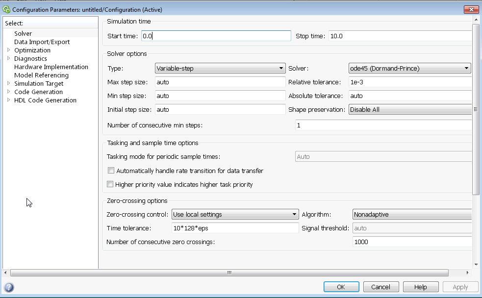
 Fixed/Variable step Tolerance (error) of simulated result Subject number 20")
20 Simulation configuration Simulation -> Model Configuration Parameters Ctrl + E Icon You can set Start/Stop time Kind of solver will be used (ode45, ode23,...) Fixed/Variable step Tolerance (error) of simulated result Subject number 20

21 Simulation configuration Subject number 21

22 Example Integrator with initial value Create simple model of integrator with initial condition Put following blocs into model Subject number 22


23 Example Integrator with initial value Configure integrator block Double click on it and select Initial condition source = external Subject number 23
24 Example Integrator with initial value Configure constant block Run the simulation Ctrl + T See the result double click on scope Subject number 24

25 Example sine wave Create following diagram Subject number 25

26 Example sine wave Configure integrator to have internal initial condition -1 Subject number 26

27 Example sine wave Run the simulation Ctrl + T See the result double click on scope Subject number 27
28 Example sine wave 2 Create following diagram Subject number 28

29 Example sine wave 2 Double click on Gain block and set the Gain to 3:1:10 In this way the vector signal will be created Subject number 29
30 Example sine wave 2 Run the simulation Ctrl + T See the result double click on scope Subject number 30

31 Useful Tricks Sometimes it is good to see dimension of the signal Display -> Signals&Ports -> Wide Nonscalar Lines, Signal Dimensions Subject number 31

32 Useful Tricks The model then look like this You can put your comment into model by double click You can change the block label Subject number 32
33 Useful Tricks You can flip the blocks by Ctrl + I You can rotate the blocks by Ctrl + R Or from the context menu Subject number 33
34 Useful Tricks In context menu (Right click on the block) You can HIDE the name of the block Change the color Subject number 34

35 Data driven modeling You can use Simulink with the Matlab Variables in Matlab can be used to specify data parameters in your model Prepare this model Subject number 35
36 Data driven modeling Configure the scope to have 3 inputs double click on scope select Number of axes 3 Subject number 36


37 Data driven modeling Configure the Zero-Order-Hold blocks Subject number 37

38 Useful Tricks Sometimes it is good to see that wires have different sample times Display -> Sample Time -> Colors Subject number 38

39 Data driven modeling Into Matlab Comand window write >> Ts = 0.5 Run the simulation Ctrl + T Subject number 39
40 Simulation commands All data can be set in m-file The simulation can be executed from m-file by comand Take the model from previous example and create following code in m-file %Simulation settings t_stop = 15; %[s] options = simset('solver','ode45'); %Start the simulation sim('sinecw',t_stop,options) Subject number 40
41 Example Mass Spring Damper System In this example we will create mass-spring-damper model in Simulink and execute it from m-file The system can be mathematically described by following equation where t is simulation time, F(t) is force applied to the system, c is damping of the spring and k is stiffness of the spring, m is mass, x(t) is actual position, its first derivative correspond to velocity and second derivative to acceleration of the mass Goal is to simulate position of the mass with respect to time Subject number 41
42 Example Mass Spring Damper System Subject number 42
43 Example Mass Spring Damper System The position can be calculated by integration of velocity and velocity can be calculated by integration of acceleration When the acting force is known the acceleration can be calculated according to second Newton s Law Force = Mass x Acceleration So the final equation is Subject number 43
44 Example Mass Spring Damper System Model in Simulink Instead of hard coding values into blocks it is useful to put them externally to a m-file. x_init dxdt_init m c k t_step_f F_beg F_step Subject number 44
45 Example Mass Spring Damper System m-file content x_init = 4; %[m] init position dxdt_init = 0; %[m/s] init speed m = 20; %[kg] mass c = 4; %[N/(m/s)] damping k = 2; %[N/m] stiffness t_step_f = 50;%[s] F_beg = 0; %[Nm] F_step = 4; %[Nm] %Simulation settings t_stop = 100; %[s] Ts = t_stop/1000; %[s] options = simset('solver','ode5','fixedstep',ts); %Start the simulation sim('msdmodel',t_stop,options); Subject number 45
46 Example Mass Spring Damper System Model Subject number 46
47 Example Mass Spring Damper System Results Subject number 47
48 Example Mass Spring Damper System Try to simulate mass-spring-damper model for different values of initial and end conditions Insert labels into model Use comments in m-file Subject number 48
49 Parameter Transfer Between Blocks Connections between blocks from outputs to inputs Drag from output to input or Click on first block, hold Ctrl and click on second block Subject number 49
50 Parameter Transfer Between Blocks Goto From blocks Pair of blocks that acts as connection For better orientation in complicated models In library Simulink - Signal Routing Pair is created by the same Goto Tag (Con1 in the picture) double click to change it or right click Block parameters Subject number 50
51 Subsystems Wraps blocks so they are not visible in current level of view Blocks are represented only by input and output ports Serves for better orientation in a complicated model Subject number 51

52 Subsystems Subject number 52

53 Subsystems - Creation Select blocks Right click Create Subsystem from Selection or Drag and drop Subsystem from library Simulink Ports and Subsystems Subsystem To look inside or change Subsystem, double click on it Subject number 53

54 Inside the Subsystem Connectivity with outer space is done by: Inports Outports These corresponds with inputs and outputs of the Subsystem block Can be renamed by clicking on its caption Subject number 54

55 Masking the Subsystem Mask of the subsystem simplifies the input of parameters in the Subsystem (e.g. constants, gains) Prompt message is shown when double clicking on Subsystem -> user does not have to search for the parameters in the subsystem itself Subject number 55

56 Creation of a Mask Right click on Subsystem Mask Create Mask or Select Subsystem and press Ctrl + M Mask Editor window is then shown Subject number 56

57 Creation of a Mask Click on Parameters & Dialog Subject number 57
 and Name Name represents the parameter value in the model Subject number")
58 Creation of a Mask Click on Parameters & Dialog Drag Edit icon from Controls panel into Parameters folder in Dialog box New line is created fill in Promp text (will be shown to user) and Name Name represents the parameter value in the model Subject number 58
 to Name that has been used in Mask Editor (here g0 ) Subject number")
59 Creation of a Mask Edit the value of the desired block (by double clicking on it) to Name that has been used in Mask Editor (here g0 ) Subject number 59
 can be entered")

60 Creation of a Mask After double clicking on Subsystem, prompt message is shown where value of the parameter(s) can be entered After execution, model calculates with entered value Default value can be set in Property editor panel in Mask editor Subject number 60

61 Masking the Subsystem Subsystem structure can be now edited by right click Mask Look Under Mask or By left click and Ctrl + U Subject number 61
62 Atomic Subsystems Normal subsystems have only visual impact on the model (better orientation for user), however blocks inside it are counted in order as without subsystem Order in which individual blocks are evaluated can be shown through menu Display Block Sorted Execution Order Subject number 62
63 Atomic Subsystems Format y:x x execution order y identification number of atomic subsystem (0 for main system) Execution order can be changed right click on block Parameters Priority the lower number, the higher priority Right click in free space of model Update Diagram (Ctrl + D) for order recalculation Normal subsystem does not affect this order Atomic subsystem does Subject number 63
64 Atomic Subsystems We might want to have the subsystem as closed unit with firm border in cases: System, with lockdown (system that can freeze ) System with response called by event (e.g. pulse counter increments value on every rising edge) Subject number 64

 and tick Treat as atomic")
65 Atomic Subsystems - Creation Drag Atomic Subsystem from Simulink Ports & Subsystems library Right click on normal Subsystem Block Parameters (Subsystem) and tick Treat as atomic unit Subject number 65


66 Atomic Subsystems Visually distinguished by bold border Execution order changed Subject number 66
 Enabled Subsystem from Ports & Subsystems or Enable block into normal subsystem Subject")
67 Enabled Subsystem Enabled subsystem works only if Enable input is in logical 1 By logical 0, the output maintains last value ( freezes ) Enabled Subsystem from Ports & Subsystems or Enable block into normal subsystem Subject number 67

68 Triggered Subsystem Makes one step based on external event (trigger) Triggered Subsystem from Ports & Subsystems or Trigger block into normal subsystem Can respond to rising or trailing edge or both To set this, double click on trigger block inside the subsystem, change parameter Trigger type Subject number 68

69 Triggered Subsystem This example transfers the value from input to output at the moment of rising edge It maintains this value on its output till next rising edge Subject number 69
70 Other Types of Subsystems Enabled and Triggered Subsystem Combination of those two For Iterator Subsystem Conducts given number of cycles within one simulation step While Iterator Subsystem Within one simulation step, it conducts cycle till the condition is fulfilled It behaves similarly as calling function from Matlab Can use only blocks without states or discrete with sampling period -1 Subject number 70
71 Action Subsystems Consist of pairs of block: condition and action If and else Condition defined in If block (double click to edit) If, else, elseif supported Multiple inputs are possible (double click to edit) Outputs for control of Action blocks Subject number 71

72 Action Subsystems Action subsystems are active when their respective action signal (if {}, else {} ) are active Pulse generator 0 1 Condition if (u1 > 0.5) Action on else: gain two times Subject number 72
73 Action Subsystems Outputs of action should be connected by Merge block (from Simulink Signal Routing library) Merge propagates the active input (from multiple inputs) If more inputs are active at the same time, it propagates the last one counted Subject number 73
74 Other Types of Subsystems Switch Case and Switch Action Subsystem As the above mentioned Action Subsystem, but this one is for switch case command For Each Subsystem For repeating same algorithm with single elements or subfields of input signal Code Reuse Subsystem Code inside is translated only once Subject number 74
75 End Thank You for Your Attention Subject number 75
Introduction to Simulink
 University College of Southeast Norway Introduction to Simulink Hans-Petter Halvorsen, 2016.11.01 http://home.hit.no/~hansha Preface Simulink, developed by The MathWorks, is a commercial tool for modeling,
Experiment 6 SIMULINK
 Experiment 6 SIMULINK Simulink Introduction to simulink SIMULINK is an interactive environment for modeling, analyzing, and simulating a wide variety of dynamic systems. SIMULINK provides a graphical user
MATLAB Examples. Simulink. Hans-Petter Halvorsen, M.Sc.
 MATLAB Examples Simulink Hans-Petter Halvorsen, M.Sc. What is Simulink? Simulink is an add-on to MATLAB. You need to have MATLAB in order to use Simulink Simulink is used for Simulation of dynamic models
Objectives. Simulink Basics
 Simulink Basics This material exempt per Department of Commerce license exception TSU Objectives After completing this module, you will be able to: Describe Simulink environment List some of the commonly
Session 3 Introduction to SIMULINK
 Session 3 Introduction to SIMULINK Brian Daku Department of Electrical Engineering University of Saskatchewan email: daku@engr.usask.ca EE 290 Brian Daku Outline This section covers some basic concepts
Experiment 8 SIMULINK
 Experiment 8 SIMULINK Simulink Introduction to simulink SIMULINK is an interactive environment for modeling, analyzing, and simulating a wide variety of dynamic systems. SIMULINK provides a graphical user
Introduction to Matlab Simulink. Control Systems
 Introduction to Matlab Simulink & their application in Control Systems ENTC 462 - Spring 2007 Introduction Simulink (Simulation and Link) is an extension of MATLAB by Mathworks Inc. It works with MATLAB
Example: Modeling a Cruise Control System in Simulink
 Example: Modeling a Cruise Control System in Simulink Physical setup and system equations Building the model Open-loop response Extracting the Model Implementing PI control Closed-loop response Physical
SIMULINK A Tutorial by Tom Nguyen
 Introduction SIMULINK A Tutorial by Tom Nguyen Simulink (Simulation and Link) is an extension of MATLAB by Mathworks Inc. It works with MATLAB to offer modeling, simulating, and analyzing of dynamical
[ MATLAB ] [ Resources ] PART TWO: SIMULINK
![[ MATLAB ] [ Resources ] PART TWO: SIMULINK](/thumbs/82/85270175.jpg "[ MATLAB ] [ Resources ] PART TWO: SIMULINK") Página 1 de 15 [ MATLAB ] [ Resources ] PART TWO: SIMULINK Contents Introduction Getting Started Handling of Blocks and Lines Annotations Some Examples NOTE: This tutorial is based on Simulink Version
Página 1 de 15 [ MATLAB ] [ Resources ] PART TWO: SIMULINK Contents Introduction Getting Started Handling of Blocks and Lines Annotations Some Examples NOTE: This tutorial is based on Simulink Version
Modeling Mechanical System using SIMULINK
 Modeling Mechanical System using SIMULINK Mechanical System We will consider a toy train consisting of an engine and a car as shown in Figure. Assuming that the train only travels in one direction, we
MATLAB AND SIMULINK. Modeling Dynamic Systems J. ABELL
 MATLAB AND SIMULINK Modeling Dynamic Systems J. ABELL Modeling Dynamic Systems Creating a Model Create an Empty Model Create a Model Template Populate a Model Copy Blocks to Your Model Browse Block Libraries
Mathematical Modelling Using SimScape (Mechanical Systems)
") Experiment Three Mathematical Modelling Using SimScape (Mechanical Systems) Control Systems Laboratory Dr. Zaer Abo Hammour Dr. Zaer Abo Hammour Control Systems Laboratory 1. Translational Mechanical System
Experiment Three Mathematical Modelling Using SimScape (Mechanical Systems) Control Systems Laboratory Dr. Zaer Abo Hammour Dr. Zaer Abo Hammour Control Systems Laboratory 1. Translational Mechanical System
Tutorial: Getting Started with the LabVIEW Simulation Module
 Tutorial: Getting Started with the LabVIEW Simulation Module - LabVIEW 8.5 Simulati... Page 1 of 10 Cart Help Search You are here: NI Home > Support > Product Reference > Manuals > LabVIEW 8.5 Simulation
SIGNALS AND LINEAR SYSTEMS LABORATORY EELE
 The Islamic University of Gaza Faculty of Engineering Electrical Engineering Department SIGNALS AND LINEAR SYSTEMS LABORATORY EELE 3110 Experiment (5): Simulink Prepared by: Eng. Mohammed S. Abuwarda Eng.
SIMULINK Tutorial. Select File-New-Model from the menu bar of this window. The following window should now appear.
 SIMULINK Tutorial Simulink is a block-orientated program that allows the simulation of dynamic systems in a block diagram format whether they are linear or nonlinear, in continuous or discrete forms. To
BME 5742 Bio-Systems Modeling and Control
 BME 5742 Bio-Systems Modeling and Control Lecture 4 Simulink Tutorial 1: Simulation of the Malthusian and Logistic Models Model Set Up, Scope Set Up Dr. Zvi Roth (FAU) 1 Getting started In the MATLAB command
INTRODUCTION TO MATLAB, SIMULINK, AND THE COMMUNICATION TOOLBOX
 INTRODUCTION TO MATLAB, SIMULINK, AND THE COMMUNICATION TOOLBOX 1) Objective The objective of this lab is to review how to access Matlab, Simulink, and the Communications Toolbox, and to become familiar
Introduction to Simulink
 Introduction to Simulink by Vinay S. K. Guntu 4310 Feedback Control Systems 1 Simulink Basics Tutorial Simulink is a graphical extension to MATLAB for modeling and simulation of systems. Advantages 1)
Experiment 3. Getting Start with Simulink
 Experiment 3 Getting Start with Simulink Objectives : By the end of this experiment, the student should be able to: 1. Build and simulate simple system model using Simulink 2. Use Simulink test and measurement
Lecture 10: Simulink. What is Simulink?
 Lecture 10: Simulink Dr. Mohammed Hawa Electrical Engineering Department University of Jordan EE201: Computer Applications. See Textbook Chapter 10. What is Simulink? Simulink is a tool for modeling, simulating
Computer Aided Design (CAD) Lecture 10. Introduction to Simulink (3) Dr.Eng. Basem ElHalawany
 Lecture 10. Introduction to Simulink (3) Dr.Eng. Basem ElHalawany") Computer Aided Design (CAD) Lecture 10 Introduction to Simulink (3) Dr.Eng. Basem ElHalawany Schedule (Updated 28-10) Topics Estimated Duration (# Lectures) Introduction 1 Introduction to Matlab Environment
Computer Aided Design (CAD) Lecture 10 Introduction to Simulink (3) Dr.Eng. Basem ElHalawany Schedule (Updated 28-10) Topics Estimated Duration (# Lectures) Introduction 1 Introduction to Matlab Environment
Simulink Basics Tutorial
 Simulink Basics Tutorial Simulink is a graphical extension to MATLAB for modeling and simulation of systems. One of the main advantages of Simulink is the ability to model a nonlinear system, which a transfer
Tutorial 17 Workflow Graphical User Interface Figure 1
 Tutorial 17 Getting Started with Modelica Objective This tutorial gives an introduction to, explaining the first steps from opening existing models and packages to modeling including result interpretation.
ME422 Mechanical Control Systems Matlab/Simulink Hints and Tips
 Cal Poly San Luis Obispo Mechanical Engineering ME Mechanical Control Systems Matlab/Simulink Hints and Tips Ridgely/Owen, last update Jan Building A Model The way in which we construct models for analyzing
SIMULINK FOR BEGINNERS:
 1 SIMULINK FOR BEGINNERS: To begin your SIMULINK session open first MATLAB ICON by clicking mouse twice and then type»simulink You will now see the Simulink block library. 2 Browse through block libraries.
ibob ADC Tutorial CASPER Reference Design
 ibob ADC Tutorial Author: Griffin Foster April 14, 2009 (v1.0) Hardware Platforms Used: ibob, iadc FPGA Clock Rate: 100 MHz Sampling Rate: 400 MHz Software Environment: TinySH This tutorial walks through
MATLAB AND MODELSIM LINKING
 MATLAB AND MODELSIM LINKING DR.S.S.Limaye Introduction: MATLAB is powerful software package for mathematical simulation, especially when signals are represented in an abstract i.e. mathematical form. When
Introduction to Simulink
 Introduction to Simulink There are several computer packages for finding solutions of differential equations, such as Maple, Mathematica, Maxima, MATLAB, etc. These systems provide both symbolic and numeric
UNIVERSITI TEKNIKAL MALAYSIA MELAKA FAKULTI KEJURUTERAAN ELEKTRONIK DAN KEJURUTERAAN KOMPUTER
 UNIVERSITI TEKNIKAL MALAYSIA MELAKA FAKULTI KEJURUTERAAN ELEKTRONIK DAN KEJURUTERAAN KOMPUTER FAKULTI KEJURUTERAAN ELEKTRONIK DAN KEJURUTERAAN KOMPUTER BENC 2113 DENC ECADD 2532 ECADD LAB SESSION 6/7 LAB
Process Automation CHEM-E7140
 Process Automation CHEM-E7140 Tutorial 3: An introduction to Simulink 1 Contents 1 Simulink: a brief introduction...2 A. Getting started...2 B. Modeling dynamic models...3 C. Creating a new model...4 D.
Embedded Systems. Problem 1: Getting started with STATEFLOW. Starting STATEFLOW
 Prof. Bernd Finkbeiner, Ph.D. Winter term 2008/2009 Dipl.-Inf. Rüdiger Ehlers Problem Set 2 Dipl.-Inf.Hans-Jörg Peter Due: Thursday,6 th November 2008 Michael Gerke, B.Sc. Embedded Systems STATEFLOW is
Starting Excel application
 MICROSOFT EXCEL 1 2 Microsoft Excel: is a special office program used to apply mathematical operations according to reading a cell automatically, just click on it. It is called electronic tables Starting
2 SIMULATING A MODEL Simulink Tutorial
 2 SIMULATING A MODEL Simulink Tutorial 1 Introduction Simulation of dynamic systems has been proven to be immensely useful in system modeling and controller design. Simulink R is a add-on to MATLAB which
Importing Models from Physical Modeling. Tools Using the FMI Standard
 Importing Models from Physical Modeling Tools Using the FMI Standard Overview The objective of this tutorial is to demonstrate the workflow for the integration of FMUs in DYNA4. The following use case
Tutorial - Exporting Models to Simulink
 Tutorial - Exporting Models to Simulink Introduction The Matlab and Simulink tools are widely used for modeling and simulation, especially the fields of control and system engineering. This tutorial will
ES205 Analysis and Design of Engineering Systems: Lab 1: An Introductory Tutorial: Getting Started with SIMULINK
 ES05 Analyi and Deign of Engineering Sytem: Lab : An Introductory Tutorial: Getting Started with SIMULINK What i SIMULINK? SIMULINK i a oftware package for modeling, imulating, and analyzing dynamic ytem.
Tutorials Tutorial 5 - TypeDesigner
 Tutorials Tutorial 5 - TypeDesigner Objective The software includes a helpful tool for creating, or extending element types - the TypeDesigner. In this tutorial we guide you step by step into the work
Rotary Motion Servo Plant: SRV02. Rotary Experiment #00: QuaRC Integration. Using SRV02 with QuaRC. Student Manual
 Rotary Motion Servo Plant: SRV02 Rotary Experiment #00: QuaRC Integration Using SRV02 with QuaRC Student Manual SRV02 QuaRC Integration Instructor Manual Table of Contents 1. INTRODUCTION...1 2. PREREQUISITES...1
the Simulation of Dynamics Using Simulink
 INTRODUCTION TO the Simulation of Dynamics Using Simulink Michael A. Gray CRC Press Taylor & Francis Croup Boca Raton London New York CRC Press is an imprint of the Taylor & Francis Group an informa business
2. Motion Analysis - Sim-Mechanics
 2 Motion Analysis - Sim-Mechanics Figure 1 - The RR manipulator frames The following table tabulates the summary of different types of analysis that is performed for the RR manipulator introduced in the
Engine with Propeller Tutorial (Professional)
") Engine with Propeller Tutorial (Professional) Copyright 2017 FunctionBay, Inc. All rights reserved. User and training documentation from FunctionBay, Inc. is subjected to the copyright laws of the Republic
Engine with Propeller Tutorial (Professional) Copyright 2017 FunctionBay, Inc. All rights reserved. User and training documentation from FunctionBay, Inc. is subjected to the copyright laws of the Republic
Assignment 2 in Simulation of Telesystems Laboratory exercise: Introduction to Simulink and Communications Blockset
 Mid Sweden University Revised: 2013-11-12 Magnus Eriksson Assignment 2 in Simulation of Telesystems Laboratory exercise: Introduction to Simulink and Communications Blockset You are expected to conclude
Inlichtingenblad, matlab- en simulink handleiding en practicumopgaven IWS
 Inlichtingenblad, matlab- en simulink handleiding en practicumopgaven IWS 4 SIMULINK 4 Simulink 4 Quick introduction General information Simulink is an etension of Matlab software for simulating dynamic
What is Simulink. >>simulink
 MATLAB Simulink What is Simulink Simulink is an input/output device GUI block diagram simulator. Simulink contains a Library Editor of tools from which we can build input/output devices and continuous
University College of Southeast Norway. Control and Simulation. in LabVIEW. Hans-Petter Halvorsen,
 University College of Southeast Norway Control and Simulation Hans-Petter Halvorsen, 2016.10.28 in LabVIEW http://home.hit.no/~hansha Preface This document explains the basic concepts of using LabVIEW
ELEC ENG 4CL4 CONTROL SYSTEM DESIGN
 ELEC ENG 4CL4 CONTROL SYSTEM DESIGN Lab #1: MATLAB/Simulink simulation of continuous casting Objectives: To gain experience in simulating a control system (controller + plant) within MATLAB/Simulink. To
Tutorial 3: Using the Waveform Viewer Introduces the basics of using the waveform viewer. Read Tutorial SIMPLIS Tutorials SIMPLIS provide a range of t
 Tutorials Introductory Tutorials These tutorials are designed to give new users a basic understanding of how to use SIMetrix and SIMetrix/SIMPLIS. Tutorial 1: Getting Started Guides you through getting
Small rectangles (and sometimes squares like this
 Lab exercise 1: Introduction to LabView LabView is software for the real time acquisition, processing and visualization of measured data. A LabView program is called a Virtual Instrument (VI) because it,
Lecture 5 Modeling Connections
 Lecture 5 Modeling Connections 16.0 Release Introduction to ANSYS Mechanical 1 2015 ANSYS, Inc. February 27, 2015 Chapter Overview In this chapter, we will extend the discussion of contact control begun
Introduction to Simulink
 Introduction to Simulink Mikael Manngård Process Control Laboratory, Åbo Akademi University February 27, 2014 Simulink is an extension to MATLAB that is used for modeling and simulation of dynamic systems.
Basic Data Acquisition with LabVIEW
 Basic Data Acquisition with LabVIEW INTRODUCTION This tutorial introduces the creation of LabView Virtual Instruments (VI s), in several individual lessons. These lessons create a simple sine wave signal,
DSP Builder User Guide
 DSP Builder User Guide 101 Innovation Drive San Jose, CA 95134 www.altera.com Software Version: 7.2 SP1 Document Date: December 2007 Copyright 2007 Altera Corporation. All rights reserved. Altera, The
Simulink Basics Tutorial
 1 of 20 1/11/2011 5:45 PM Starting Simulink Model Files Basic Elements Running Simulations Building Systems Simulink Basics Tutorial Simulink is a graphical extension to MATLAB for modeling and simulation
Tutorial 1 Getting Started
 by Tutorial 1 Getting Started Objective The following tutorial is a step-by-step introduction to the basics of SimulationX. You will first get an overview of the graphical user interface (GUI) with the
Systems & Control Lab.-Manual
 German University in Cairo - GUC Information Engineering and Technology Electronics, Communications, & Networks Systems & Control Lab.-Manual (3) A brief overview of: By: Eng. Moustafa Adly ON-OFF control
Modeling an Impulse in Simulink
 INTRODUCTION Often a dynamic system is subject to an impulsive load, such as a blow from a hammer. It is important to be able to model such systems to understand what the response will be. This tutorial
UNIVERSITI TEKNIKAL MALAYSIA MELAKA FAKULTI KEJURUTERAAN ELEKTRONIK DAN KEJURUTERAAN KOMPUTER
 UNIVERSITI TEKNIKAL MALAYSIA MELAKA FAKULTI KEJURUTERAAN ELEKTRONIK DAN KEJURUTERAAN KOMPUTER FAKULTI KEJURUTERAAN ELEKTRONIK DAN KEJURUTERAAN KOMPUTER BENC 2113 DENC ECADD 2532 ECADD LAB SESSION 6/7 LAB
Introduction to MATLAB
 Introduction to MATLAB Introduction MATLAB is an interactive package for numerical analysis, matrix computation, control system design, and linear system analysis and design available on most CAEN platforms
Introduction to ANSYS Mechanical
 Lecture 6 Modeling Connections 15.0 Release Introduction to ANSYS Mechanical 1 2012 ANSYS, Inc. February 12, 2014 Chapter Overview In this chapter, we will extend the discussion of contact control begun
S206E Lecture 13, 5/22/2016, Grasshopper Math and Logic Rules
 S206E057 -- Lecture 13, 5/22/2016, Grasshopper Math and Logic Rules Copyright 2016, Chiu-Shui Chan. All Rights Reserved. Interface of Math and Logic Functions 1. Basic mathematic operations: For example,
Experiment 1: Introduction to Labview 8.0 (tbc 1/7/2007, 1/13/2009,1/13/2011)
") Experiment 1: Introduction to Labview 8.0 (tbc 1/7/2007, 1/13/2009,1/13/2011) Objective: To learn how to build virtual instrument panels in Labview 8.0 Tasks: 1. Build the Labview VI shown in the tutorial
Experiment 1: Introduction to Labview 8.0 (tbc 1/7/2007, 1/13/2009,1/13/2011) Objective: To learn how to build virtual instrument panels in Labview 8.0 Tasks: 1. Build the Labview VI shown in the tutorial
MapleSim User's Guide
 MapleSim User's Guide Copyright Maplesoft, a division of Waterloo Maple Inc. 2001-2009 MapleSim User's Guide Copyright Maplesoft, MapleSim, and Maple are all trademarks of Waterloo Maple Inc. Maplesoft,
GIMP WEB 2.0 BADGES. GIMP is all about IT (Images and Text) OPEN GIMP
 OPEN GIMP") GIMP WEB 2.0 BADGES and Badges: Circle with Flap Completed Project WEB 2.0 BADGES: CIRCLE WITH FLAP GIMP is all about IT (Images and Text) OPEN GIMP Step 1: To begin a new GIMP project, from the Menu Bar,
GIMP WEB 2.0 BADGES and Badges: Circle with Flap Completed Project WEB 2.0 BADGES: CIRCLE WITH FLAP GIMP is all about IT (Images and Text) OPEN GIMP Step 1: To begin a new GIMP project, from the Menu Bar,
UNIT 5. Simulink. 1. Introduction
 UNIT 5 Simulink 1. Introduction... 1 2. Simulink... 2 2.1 Starting Simulink... 2 2.2 Model building... 3 2.3 Simulation parameters and Scope block... 5 2.4 Subsystems and masks... 11 2.5 S Functions...
This knowledge was gained partially through trial and error, but largely thanks to the help of the folks at CASPER.
 CICADA Note #6 CASPER Tool-flow Development Notes Brandon Rumberg, Patrick Brandt NRAO Green Bank 8/9/07 This document is meant to compile some of the things about using the CASPER tool-flow that we didn't
Introduction to Electronics Workbench
 Introduction to Electronics Workbench Electronics Workbench (EWB) is a design tool that provides you with all the components and instruments to create board-level designs on your PC. The user interface
University College of Southeast Norway MATLAB. Part III: Simulink and Advanced Topics. Hans-Petter Halvorsen,
 University College of Southeast Norway MATLAB Part III: Simulink and Advanced Topics Hans-Petter Halvorsen, 2017.06.19 http://www.halvorsen.blog Preface Copyright You cannot distribute or copy this document
Setup Examples. NetArrays Project Program Development
 Setup Examples NetArrays Project Program Development NetArrays Project Program Development Example 2005, 2007, 2008, 2009 RTP Corporation Not for reproduction in any printed or electronic media without
Ansys Designer RF Training Lecture 2: Introduction to the Designer GUI
 Ansys Designer RF Solutions for RF/Microwave Component and System Design 7. 0 Release Ansys Designer RF Training Lecture 2: Introduction to the Designer GUI Ansoft Designer Desktop Menu bar Toolbars Schematic
Graphical User Interface. GUI in MATLAB. Eng. Banan Ahmad Allaqta
 raphical ser nterface in MATLAB Eng. Banan Ahmad Allaqta What is? A graphical user interface () is a graphical display in one or more windows containing controls, called components, that enable a user
What s New in Simulink Release R2016a and R2016b
 What s New in Simulink Release R2016a and R2016b Mark Walker 2015 The MathWorks, Inc. 1 What s New in Simulink R2016a/b 2 What s New in Simulink R2016a/b 3 Our Objectives with Simulink R2016b Provide immediate
DOING MORE WITH EXCEL: MICROSOFT OFFICE 2013
 DOING MORE WITH EXCEL: MICROSOFT OFFICE 2013 GETTING STARTED PAGE 02 Prerequisites What You Will Learn MORE TASKS IN MICROSOFT EXCEL PAGE 03 Cutting, Copying, and Pasting Data Basic Formulas Filling Data
AADL Graphical Editor Design
 AADL Graphical Editor Design Peter Feiler Software Engineering Institute phf@sei.cmu.edu Introduction An AADL specification is a set of component type and implementation declarations. They are organized
MODELING IN SCILAB: PAY ATTENTION TO THE RIGHT
 powered by MODELING IN SCILAB: PAY ATTENTION TO THE RIGHT APPROACH PART 2 In this tutorial we show how to model a physical system described by ODE using Xcos environment. The same model solution is also
Automotive Data Dictionary
 ADD V3.7 Visual Information Technologies GmbH Automotive Data Dictionary What s new in Version 3.7? October 29 th 2008 ADD Contact email: add@visu-it.de Internet: http://www.visu-it.de/add Copyright 2008
A Comprehensive Look at Foxtrot s Action Library
 FOXTROT ACTIONS Foxtrot RPA s Smart Technology will always present the user with the Actions that are relevant to the target. A Comprehensive Look at Foxtrot s Action Library Add Sheet Arrange Workbooks
Working with the RTF Generator
 Using EA Working with the RTF Generator by Dermot O Bryan All material Sparx Systems 2008 Sparx Systems 2008 Page 1 Trademarks Microsoft, Microsoft Word are trademarks or registered trademarks of the Microsoft
Microsoft Excel 2013: Excel Basics June 2014
 Microsoft Excel 2013: Excel Basics June 2014 Description Excel is a powerful spreadsheet program. Please note that in this class we will use Excel 2010 or 2013. Learn how to create spreadsheets, enter
How to Build a Simple Stateflow Model. Jim Freudenberg University of Michigan EECS 461: Embedded Control Systems
 How to Build a Simple Stateflow Model Jim Freudenberg University of Michigan EECS 461: Embedded Control Systems IntroducFon This set of slides will show you how build a simple model using Simulink and
Microsoft Excel 2007
 Microsoft Excel 2007 1 Excel is Microsoft s Spreadsheet program. Spreadsheets are often used as a method of displaying and manipulating groups of data in an effective manner. It was originally created
CECOS University Department of Electrical Engineering. Wave Propagation and Antennas LAB # 1
 CECOS University Department of Electrical Engineering Wave Propagation and Antennas LAB # 1 Introduction to HFSS 3D Modeling, Properties, Commands & Attributes Lab Instructor: Amjad Iqbal 1. What is HFSS?
Introduction to the MATLAB SIMULINK Program
 Introduction to the MATLAB SIMULINK Program Adapted from similar document by Dept. of Chemical Engineering, UC - Santa Barbara MATLAB, which stands for MATrix LABoratory, is a technical computing environment
What s New in MATLAB and Simulink The MathWorks, Inc. 1
 What s New in MATLAB Simulink 2015 The MathWorks, Inc. 1 Engineers scientists 2 Engineers scientists Develop algorithms Analyze data write MATLAB code. 3 Engineers scientists deploy algorithms applications
1 Ctrl + X Cut the selected item. 2 Ctrl + C (or Ctrl + Insert) Copy the selected item. 3 Ctrl + V (or Shift + Insert) Paste the selected item
 Copy the selected item. 3 Ctrl + V (or Shift + Insert) Paste the selected item") Tips and Tricks Recorder Actions Library XPath Syntax Hotkeys Windows Hotkeys General Keyboard Shortcuts Windows Explorer Shortcuts Command Prompt Shortcuts Dialog Box Keyboard Shortcuts Excel Hotkeys
Tips and Tricks Recorder Actions Library XPath Syntax Hotkeys Windows Hotkeys General Keyboard Shortcuts Windows Explorer Shortcuts Command Prompt Shortcuts Dialog Box Keyboard Shortcuts Excel Hotkeys
Workbench Tutorial Flow Over an Airfoil, Page 1 ANSYS Workbench Tutorial Flow Over an Airfoil
 Workbench Tutorial Flow Over an Airfoil, Page 1 ANSYS Workbench Tutorial Flow Over an Airfoil Authors: Scott Richards, Keith Martin, and John M. Cimbala, Penn State University Latest revision: 17 January
An Introduction to Using Simulink
 An Introduction to Using Simulink COURSE NOTES Eric Peasley, Department of Engineering Science, University of Oxford Adapted and updated by Dr I. F. Mear using MATLAB 2017b and MATLAB 2018b version 5.0,
How to Make Graphs with Excel 2007
 Appendix A How to Make Graphs with Excel 2007 A.1 Introduction This is a quick-and-dirty tutorial to teach you the basics of graph creation and formatting in Microsoft Excel. Many of the tasks that you
Quick Start Training Guide
 Quick Start Training Guide Table of Contents 1 INTRODUCTION TO MAPLESIM... 5 1.1 USER INTERFACE... 5 2 WORKING WITH A SAMPLE MODEL... 7 2.1 RUNNING A SIMULATION... 7 2.2 GRAPHICAL OUTPUT... 7 2.3 3D VISUALIZATION...
Word 2016 Advanced. North American Edition SAMPLE
 Word 2016 Advanced Word 2016 Advanced North American Edition WORD 2016 ADVANCED Page 2 2015 Cheltenham Group Pty. Ltd. All trademarks acknowledged. E&OE. No part of this document may be copied without
Appendix A. HINTS WHEN USING EXCEL w
 Appendix A HINTS WHEN USING EXCEL w This appendix provides hints when using Microsoft Excel. Appendix A includes general features that are useful in all the applications solved with Excel in this book.
FMI Kit for Simulink version by Dassault Systèmes
 FMI Kit for Simulink version 2.4.0 by Dassault Systèmes April 2017 The information in this document is subject to change without notice. Copyright 1992-2017 by Dassault Systèmes AB. All rights reserved.
Interpreting Data in IX1D v 3 A Tutorial
 Interpreting Data in IX1D v 3 A Tutorial Version 1.0 2006 Interpex Limited All rights reserved Select a Sounding from the Map Display using the Mouse If you right-click on the sounding, there are more
SolidWorks Motion Study Tutorial
 SolidWorks Motion Study Tutorial By: Mohamed Hakeem Mohamed Nizar Mechanical Engineering Student- May 2015 South Dakota School of Mines & Technology August 2013 Getting Started This tutorial is for you
Corel Ventura 8 Introduction
 Corel Ventura 8 Introduction Training Manual A! ANZAI 1998 Anzai! Inc. Corel Ventura 8 Introduction Table of Contents Section 1, Introduction...1 What Is Corel Ventura?...2 Course Objectives...3 How to
A Guide to Processing Photos into 3D Models Using Agisoft PhotoScan
 A Guide to Processing Photos into 3D Models Using Agisoft PhotoScan Samantha T. Porter University of Minnesota, Twin Cities Fall 2015 Index 1) Automatically masking a black background / Importing Images.
Compressible Flow in a Nozzle
 SPC 407 Supersonic & Hypersonic Fluid Dynamics Ansys Fluent Tutorial 1 Compressible Flow in a Nozzle Ahmed M Nagib Elmekawy, PhD, P.E. Problem Specification Consider air flowing at high-speed through a
Lab 2 Modeling from an observed response
 Lab 2 Modeling from an observed response Agenda Time Item 5 min Lab introduction The big picture of system modeling in the time domain 5 min The SEE, to quantify the goodness of fit 5 min Demonstration
Excel Select a template category in the Office.com Templates section. 5. Click the Download button.
 Microsoft QUICK Excel 2010 Source Getting Started The Excel Window u v w z Creating a New Blank Workbook 2. Select New in the left pane. 3. Select the Blank workbook template in the Available Templates
ProMoT Step by Step for Reaction Models in Process Engineering A Tutorial
 ProMoT Step by Step for Reaction Models in Process Engineering A Tutorial Martin Ginkel, Sebastian Mirschel, Katrin Kolczyk August 19, 2011 http://www.mpi-magdeburg.mpg.de/projects/promot/ promot@mpi-magdeburg.mpg.de