Abaqus CAE Tutorial 6: Contact Problem
|
|
|
- Alberta Butler
- 6 years ago
- Views:
Transcription
 is modeled by displacing the upper portion by a prescribed amount and investigating the resulting contact region and")
1 ENGI 7706/7934: Finite Element Analysis Abaqus CAE Tutorial 6: Contact Problem Problem Description In this problem, a segment of an electrical contact switch (steel) is modeled by displacing the upper portion by a prescribed amount and investigating the resulting contact region and stress.
 3.")
. a. Note: The right vertical edge of the switch does not need to be drawn.")
2 Analysis Steps 1. Start Abaqus and choose to create a new model database 2. In the model tree double click on the Parts node (or right click on parts and select Create) 3. In the Create Part dialog box (shown above) name the part and a. Select 3D b. Select Deformable c. Select Shell d. Select Extrusion e. Set approximate size = 50 f. Click Continue 4. Create the geometry shown below (not discussed here). a. Note: The right vertical edge of the switch does not need to be drawn. b. Click Done c. Set Depth = 2 d. Click OK


3 5. To aid in mesh refinement and assigning contact surfaces, we want to partition the lower half of the switch. a. In the toolbox area click on the Partition Face: Sketch icon. b. Select the lower half of the switch and click Done c. Select the right edge of the lower half of the switch. d. In the toolbar, click on the Iso View icon. i. Note: If the View toolbar is not visible go to the menu View Toolbars Views e. In the toolbox area click on the Project Edges icon. f. Select the highest edge of the top half of the switch as shown. Click Done twice. g. Click Done to accept partition geometry.

")
4 6. Double click on the Materials node in the model tree a. Name the new material and give it a description b. Click on the Mechanical tab Elasticity Elastic c. Define Young s Modulus and the Poisson s Ratio (use SI (mm) units) d. Click OK


5 7. Double click on the Sections node in the model tree a. Name the section ShellProperties and select Shell for the category and Homogeneous for the type b. Click Continue c. Select the material created above (Steel) and set the thickness to 0.15 d. Click OK 8. Expand the Parts node in the model tree, expand the node of the part just created, and double click on Section Assignments a. Select the entire geometry in the viewport and press Done in the prompt area b. Select the section created above (ShellProperties) c. Specify shell offset if necessary d. Click OK


6 e. In the menu bar select Assign Element Normal f. Select the lower half of the switch, click Done g. The purple faces of the contact areas should now be facing each other. i. Note: The geometry may start with the purple faces up, in which case you will have to flip the orientation of the top surface. The end goal is that you have the purple faces of the two contacting surfaces facing each other. 9. Expand the Assembly node in the model tree and then double click on Instances a. Select Dependent for the instance type b. Click OK


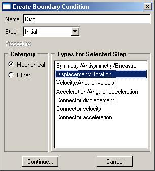
7 10. Double click on the Steps node in the model tree a. Name the step, set the procedure to General, select Static, General, and click Continue b. Accept the default settings, click OK 11. Double click on the BCs node in the model tree a. Name the boundary conditioned Fixed and select Symmetry/Antisymmetry/Encastre for the type


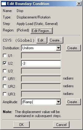
8 b. Select the right edge of both halves of the switch and click Done c. Select ENCASTRE for the boundary condition and click OK 12. Double click on the BCs node in the model tree a. Name the boundary conditioned Disp and select Displacement/Rotation for the type b. Select the top edge of the triangular portion of the geometry c. Set the y displacement to 3, click OK
9


10 13. Double click on the Interaction Properties node in the model tree a. Name the interaction properties and select Contact for the type, click Continue b. On the Mechanical tab Select Tangential Behavior i. Set the friction formulation to Frictionless c. On the Mechanical tab Select Normal Behavior i. Because the surfaces do not start in contact, change the constraint enforcement method to Penalty d. Click OK 14. Double click on the Interactions node in the model tree a. Name the interaction, select Surface to surface contact, and click continue b. For the master surface select the lower portion of the geometry at the free end and click done


11 i. While applying the fixed displacement, the nodes at the tip of the upper portion of the geometry will make contact at an unknown location on the lower surface ii. Nodes on the slave surface cannot penetrate the surface formed by the element faces on the master surface c. Select the color of the surface corresponding to the top surface d. For the slave surface, set the slave type to Surface e. Select the upper portion of the geometry at the free end and click done f. Select the color of the surface corresponding to the bottom surface g. Change the contact interaction properties to the one created above (if not already done) h. Click OK


12 15. In the model tree double click on Mesh for the Switch part, and in the toolbox area click on the Assign Element Type icon a. Select all of the geometry b. Select Standard for element type c. Select Linear for geometric order d. Select Shell for family e. Note that the name of the element (S4R) and its description are given below the element controls f. Select OK


13 16. In the toolbox area click on the Assign Mesh Controls icon a. Select all of the geometry b. Change the element shape to Quad c. Change the technique to Structured 17. In the toolbox area click on the Seed Edges icon a. Select the two fixed edges, click Done b. Select By number c. Set Bias to None d. Under Sizing Controls enter 8 elements, Click OK


14 18. In the toolbox area ensure the Seed Edges icon is still selected a. Select the edges indicated below b. Set Method to By Size and Bias to Double c. Set Minimum size to 0.25 and Maximum size to 1, click OK 19. In the toolbox area ensure the Seed Edges icon is still selected a. Select the remaining edges indicated below b. Set Method to By Size and Bias to None c. Set Approximate element size to 0.25, click OK


15 20. In the toolbox area click on the Mesh Part icon a. Click Yes 21. In the model tree double click on the Job node a. Name the job switch b. Give the job a description, click Continue c. Accept defaults, click OK
 Mises stress overlaid with the undeformed geometry a.")

16 22. In the model tree right click on the submitted and successfully completed job, and select Results 23. Display the deformed contour of the (Von) Mises stress overlaid with the undeformed geometry a. In the toolbox area click on the following icons i. Plot Contours on Deformed Shape ii. Allow Multiple Plot States iii. Plot Undeformed Shape 24. In the toolbox area click on the Common Plot Options icon a. Set the Deformation Scale Factor to 1 b. Click OK
 b.")
17 25. To change the output being displayed, in the menu bar click on Results Field Output a. Select the contact pressure at surface nodes (CPRESS) b. Click OK
Abaqus/CAE Axisymmetric Tutorial (Version 2016)
") Abaqus/CAE Axisymmetric Tutorial (Version 2016) Problem Description A round bar with tapered diameter has a total load of 1000 N applied to its top face. The bottom of the bar is completely fixed. Determine
Abaqus/CAE Axisymmetric Tutorial (Version 2016) Problem Description A round bar with tapered diameter has a total load of 1000 N applied to its top face. The bottom of the bar is completely fixed. Determine
Analysis Steps 1. Start Abaqus and choose to create a new model database
 Source: Online tutorials for ABAQUS Problem Description The two dimensional bridge structure, which consists of steel T sections (b=0.25, h=0.25, I=0.125, t f =t w =0.05), is simply supported at its lower
Abaqus/CAE (ver. 6.10) Stringer Tutorial
 Stringer Tutorial") Abaqus/CAE (ver. 6.10) Stringer Tutorial Problem Description A table made of steel tubing with a solid steel top and shelf is loaded with an oblique impulse load. Determine the transient response of the
Abaqus/CAE (ver. 6.10) Stringer Tutorial Problem Description A table made of steel tubing with a solid steel top and shelf is loaded with an oblique impulse load. Determine the transient response of the
Abaqus/CAE (ver. 6.9) Vibrations Tutorial
 Vibrations Tutorial") Abaqus/CAE (ver. 6.9) Vibrations Tutorial Problem Description The two dimensional bridge structure, which consists of steel T sections, is simply supported at its lower corners. Determine the first 10
Abaqus/CAE (ver. 6.9) Vibrations Tutorial Problem Description The two dimensional bridge structure, which consists of steel T sections, is simply supported at its lower corners. Determine the first 10
Appendix B: Creating and Analyzing a Simple Model in Abaqus/CAE
 Getting Started with Abaqus: Interactive Edition Appendix B: Creating and Analyzing a Simple Model in Abaqus/CAE The following section is a basic tutorial for the experienced Abaqus user. It leads you
Abaqus/CAE (ver. 6.12) Vibrations Tutorial
 Vibrations Tutorial") Abaqus/CAE (ver. 6.12) Vibrations Tutorial Problem Description The two dimensional bridge structure, which consists of steel T sections, is simply supported at its lower corners. Determine the first 10
Abaqus/CAE (ver. 6.12) Vibrations Tutorial Problem Description The two dimensional bridge structure, which consists of steel T sections, is simply supported at its lower corners. Determine the first 10
Creating and Analyzing a Simple Model in Abaqus/CAE
 Appendix B: Creating and Analyzing a Simple Model in Abaqus/CAE The following section is a basic tutorial for the experienced Abaqus user. It leads you through the Abaqus/CAE modeling process by visiting
Abaqus/CAE Heat Transfer Tutorial
 Abaqus/CAE Heat Transfer Tutorial Problem Description The thin L shaped steel part shown above (lengths in meters) is exposed to a temperature of 20 o C on the two surfaces of the inner corner, and 120
ABAQUS/CAE Workshops
 ABAQUS/CAE Workshops University of Birmingham ABAQUS Training 27 th / 28 th October 2009 Workshop 1a: Create 3D Part Type: abaqus cae at the command prompt or select abaqus V6.9-1 from the start menu.
Abaqus CAE Tutorial 1: 2D Plane Truss
 ENGI 7706/7934: Finite Element Analysis Abaqus CAE Tutorial 1: 2D Plane Truss Lab TA: Xiaotong Huo EN 3029B xh0381@mun.ca Download link for Abaqus student edition: http://academy.3ds.com/software/simulia/abaqus-student-edition/
CE366/ME380 Finite Elements in Applied Mechanics I Fall 2007
 CE366/ME380 Finite Elements in Applied Mechanics I Fall 2007 FE Project 1: 2D Plane Stress Analysis of acantilever Beam (Due date =TBD) Figure 1 shows a cantilever beam that is subjected to a concentrated
Abaqus/CAE (ver. 6.11) Nonlinear Buckling Tutorial
 Nonlinear Buckling Tutorial") Abaqus/CAE (ver. 6.11) Nonlinear Buckling Tutorial Problem Description This is the NAFEMS 1 proposed benchmark (Lee s frame buckling) problem. The applied load is based on the normalized (EI/L 2 ) value
Abaqus/CAE (ver. 6.11) Nonlinear Buckling Tutorial Problem Description This is the NAFEMS 1 proposed benchmark (Lee s frame buckling) problem. The applied load is based on the normalized (EI/L 2 ) value
Fully-Coupled Thermo-Mechanical Analysis
 Fully-Coupled Thermo-Mechanical Analysis Type of solver: ABAQUS CAE/Standard Adapted from: ABAQUS Example Problems Manual Extrusion of a Cylindrical Aluminium Bar with Frictional Heat Generation Problem
Workshop 15. Single Pass Rolling of a Thick Plate
 Introduction Workshop 15 Single Pass Rolling of a Thick Plate Rolling is a basic manufacturing technique used to transform preformed shapes into a form suitable for further processing. The rolling process
FINITE ELEMENT ANALYSIS OF A PLANAR TRUSS
 Problem Description: FINITE ELEMENT ANALYSIS OF A PLANAR TRUSS Instructor: Professor James Sherwood Revised: Dimitri Soteropoulos Programs Utilized: Abaqus/CAE 6.11-2 This tutorial explains how to build
Torsional-lateral buckling large displacement analysis with a simple beam using Abaqus 6.10
 Torsional-lateral buckling large displacement analysis with a simple beam using Abaqus 6.10 This document contains an Abaqus tutorial for performing a buckling analysis using the finite element program
Installation Guide. Beginners guide to structural analysis
 Installation Guide To install Abaqus, students at the School of Civil Engineering, Sohngaardsholmsvej 57, should log on to \\studserver, whereas the staff at the Department of Civil Engineering should
Sliding Split Tube Telescope
 LESSON 15 Sliding Split Tube Telescope Objectives: Shell-to-shell contact -accounting for shell thickness. Creating boundary conditions and loads by way of rigid surfaces. Simulate large displacements,
EN1740 Computer Aided Visualization and Design Spring /26/2012 Brian C. P. Burke
 EN1740 Computer Aided Visualization and Design Spring 2012 4/26/2012 Brian C. P. Burke Last time: More motion analysis with Pro/E Tonight: Introduction to external analysis products ABAQUS External Analysis
ME Optimization of a Frame
 ME 475 - Optimization of a Frame Analysis Problem Statement: The following problem will be analyzed using Abaqus. 4 7 7 5,000 N 5,000 N 0,000 N 6 6 4 3 5 5 4 4 3 3 Figure. Full frame geometry and loading
This tutorial will take you all the steps required to set up and run a basic simulation using ABAQUS/CAE and visualize the results;
 ENGN 1750: Advanced Mechanics of Solids ABAQUS TUTORIAL School of Engineering Brown University This tutorial will take you all the steps required to set up and run a basic simulation using ABAQUS/CAE and
Multi-Step Analysis of a Cantilever Beam
 LESSON 4 Multi-Step Analysis of a Cantilever Beam LEGEND 75000. 50000. 25000. 0. -25000. -50000. -75000. 0. 3.50 7.00 10.5 14.0 17.5 21.0 Objectives: Demonstrate multi-step analysis set up in MSC/Advanced_FEA.
This tutorial will take you all the steps required to import files into ABAQUS from SolidWorks
 ENGN 1750: Advanced Mechanics of Solids ABAQUS CAD INTERFACE TUTORIAL School of Engineering Brown University This tutorial will take you all the steps required to import files into ABAQUS from SolidWorks
Manual for Computational Exercises
 Manual for the computational exercise in TMM4160 Fracture Mechanics Page 1 of 32 TMM4160 Fracture Mechanics Manual for Computational Exercises Version 3.0 Zhiliang Zhang Dept. of Structural Engineering
Manual for Abaqus CAE Topology Optimization
 Abaqus CAE access: Manual for Abaqus CAE Topology Optimization 1. Open Exceed ondemand Client -> login and pass 2FA 2. Select Desktop_Mode_Full_Screen (or other user preferred resolution) for XConfig and
Exercise 1. 3-Point Bending Using the Static Structural Module of. Ansys Workbench 14.0
 Exercise 1 3-Point Bending Using the Static Structural Module of Contents Ansys Workbench 14.0 Learn how to...1 Given...2 Questions...2 Taking advantage of symmetries...2 A. Getting started...3 A.1 Choose
ABAQUS for CATIA V5 Tutorials
 ABAQUS for CATIA V5 Tutorials AFC V2.5 Nader G. Zamani University of Windsor Shuvra Das University of Detroit Mercy SDC PUBLICATIONS Schroff Development Corporation www.schroff.com ABAQUS for CATIA V5,
Linear Bifurcation Buckling Analysis of Thin Plate
 LESSON 13a Linear Bifurcation Buckling Analysis of Thin Plate Objectives: Construct a quarter model of a simply supported plate. Place an edge load on the plate. Run an Advanced FEA bifurcation buckling
FINITE ELEMENT ANALYSIS OF A PLANAR TRUSS
 FINITE ELEMENT ANALYSIS OF A PLANAR TRUSS Instructor: Professor James Sherwood Revised: Michael Schraiber, Dimitri Soteropoulos Programs Utilized: HyperMesh Desktop v12.0, OptiStruct, HyperView This tutorial
CHAPTER 8 FINITE ELEMENT ANALYSIS
 If you have any questions about this tutorial, feel free to contact Wenjin Tao (w.tao@mst.edu). CHAPTER 8 FINITE ELEMENT ANALYSIS Finite Element Analysis (FEA) is a practical application of the Finite
Stiffened Plate With Pressure Loading
 Supplementary Exercise - 3 Stiffened Plate With Pressure Loading Objective: geometry and 1/4 symmetry finite element model. beam elements using shell element edges. MSC.Patran 301 Exercise Workbook Supp3-1
Figure E3-1 A plane struss structure under applied loading. Start MARC Designer. From the main menu, select STATIC STRESS ANALYSIS.
 Example 3 Static Stress Analysis on a Plane Truss Structure Problem Statement: In this exercise, you will use MARC Designer software to carry out a static stress analysis on a simple plane truss structure,
Chapter 2. Structural Tutorial
 Chapter 2. Structural Tutorial Tutorials> Chapter 2. Structural Tutorial Static Analysis of a Corner Bracket Problem Specification Problem Description Build Geometry Define Materials Generate Mesh Apply
file://c:\documents and Settings\sala\Configuración local\temp\~hha54f.htm
 Página 1 de 26 Tutorials Chapter 2. Structural Tutorial 2.1. Static Analysis of a Corner Bracket 2.1.1. Problem Specification Applicable ANSYS Products: Level of Difficulty: Interactive Time Required:
Revised Sheet Metal Simulation, J.E. Akin, Rice University
 Revised Sheet Metal Simulation, J.E. Akin, Rice University A SolidWorks simulation tutorial is just intended to illustrate where to find various icons that you would need in a real engineering analysis.
Sliding Block LESSON 26. Objectives: Demonstrate the use of Contact LBCs in a simple exercise.
 LESSON 26 Sliding Block 5 Objectives: Demonstrate the use of Contact LBCs in a simple exercise. Present method for monitoring a non-linear analysis progress. 26-1 26-2 LESSON 26 Sliding Block Model Description:
1.992, 2.993, 3.04, 10.94, , Introduction to Modeling and Simulation Prof. F.-J. Ulm Spring FE Modeling Example Using ADINA
 1.992, 2.993, 3.04, 10.94, 18.996, 22.091 Introduction to Modeling and Simulation Prof. F.-J. Ulm Spring 2002 FE Modeling Example Using ADINA H Hgρ w ργ H = B = 10 m g = 9.81 m/s 2 ρ = 2400 kg/m 3 ρ w
FEA BENDING, TORSION, TENSION, and SHEAR TUTORIAL in CATIA
 1 FEA BENDING, TORSION, TENSION, and SHEAR TUTORIAL in CATIA This tutorial shows the basics of a solid bending, torsional, tension, and shear FEA (Finite Elemental Analysis) model in CATIA. Torsion - page
Exercise 1. 3-Point Bending Using the GUI and the Bottom-up-Method
 Exercise 1 3-Point Bending Using the GUI and the Bottom-up-Method Contents Learn how to... 1 Given... 2 Questions... 2 Taking advantage of symmetries... 2 A. Preprocessor (Setting up the Model)... 3 A.1
ES 128: Computer Assignment #4. Due in class on Monday, 12 April 2010
 ES 128: Computer Assignment #4 Due in class on Monday, 12 April 2010 Task 1. Study an elastic-plastic indentation problem. This problem combines plasticity with contact mechanics and has many rich aspects.
FINITE ELEMENT ANALYSIS OF A PLANAR TRUSS
 FINITE ELEMENT ANALYSIS OF A PLANAR TRUSS Instructor: Professor James Sherwood Revised: Michael Schraiber, Dimitri Soteropoulos, Sanjay Nainani Programs Utilized: HyperMesh Desktop v2017.2, OptiStruct,
Introduction to MSC.Patran
 Exercise 1 Introduction to MSC.Patran Objectives: Create geometry for a Beam. Add Loads and Boundary Conditions. Review analysis results. MSC.Patran 301 Exercise Workbook - Release 9.0 1-1 1-2 MSC.Patran
Learning Module 8 Shape Optimization
 Learning Module 8 Shape Optimization What is a Learning Module? Title Page Guide A Learning Module (LM) is a structured, concise, and self-sufficient learning resource. An LM provides the learner with
Abaqus 6.9SE Handout
 MANE 4240/ CIVL 4240: Introduction to Finite Elements Abaqus 6.9SE Handout Professor Suvranu De Department of Mechanical, Aerospace and Nuclear Engineering Rensselaer Polytechnic Institute Table of Contents
ME 475 FEA of a Composite Panel
 ME 475 FEA of a Composite Panel Objectives: To determine the deflection and stress state of a composite panel subjected to asymmetric loading. Introduction: Composite laminates are composed of thin layers
Tutorial 23: Sloshing in a tank modelled using SPH as an example
 Tutorial 23: Sloshing in a tank modelled using SPH as an example This tutorial gives a basic introduction to SPH modelling in Abaqus CAE. The tutorial will take you through a basic model of g forces acting
ANSYS Workbench Guide
 ANSYS Workbench Guide Introduction This document serves as a step-by-step guide for conducting a Finite Element Analysis (FEA) using ANSYS Workbench. It will cover the use of the simulation package through
A plate with a hole is subjected to tension as shown: z p = 25.0 N/mm 2
 Problem description A plate with a hole is subjected to tension as shown: z p = 25.0 N/mm 2 56 y All lengths in mm. Thickness =1mm E = 7.0 10 4 N/mm = 0.25 10 20 This is the same problem as problem 2.
The Essence of Result Post- Processing
 APPENDIX E The Essence of Result Post- Processing Objectives: Manually create the geometry for the tension coupon using the given dimensions then apply finite elements. Manually define material and element
ME Optimization of a Truss
 ME 475 - Optimization of a Truss Analysis Problem Statement: The following problem will be analyzed using Abaqus and optimized using HEEDS. 4 5 8 2 11 3 10 6 9 1 7 12 6 m 300 kn 300 kn 22 m 35 m Figure
Module 1.7W: Point Loading of a 3D Cantilever Beam
 Module 1.7W: Point Loading of a 3D Cantilever Beam Table of Contents Page Number Problem Description 2 Theory 2 Workbench Analysis System 4 Engineering Data 5 Geometry 6 Model 11 Setup 13 Solution 14 Results
A pipe bend is subjected to a concentrated force as shown: y All dimensions in inches. Material is stainless steel.
 Problem description A pipe bend is subjected to a concentrated force as shown: y 15 12 P 9 Displacement gauge Cross-section: 0.432 18 x 6.625 All dimensions in inches. Material is stainless steel. E =
Linear Static Analysis of a Simply-Supported Stiffened Plate
 WORKSHOP 7 Linear Static Analysis of a Simply-Supported Stiffened Plate Objectives: Create a geometric representation of a stiffened plate. Use the geometry model to define an analysis model comprised
STEPS BY STEPS FOR THREE-DIMENSIONAL ANALYSIS USING ABAQUS STEADY-STATE HEAT TRANSFER ANALYSIS
 UNIVERSITI MALAYSIA PERLIS FACULTY OF ENGINEERING TECHNOLOGY DEPARTMENT OF MECHANICAL ENGINEERING TECHNOLOGY PDT348 FINITE ELEMENT ANALYSIS Semester II 2017/2018 STEPS BY STEPS FOR THREE-DIMENSIONAL ANALYSIS
3. Preprocessing of ABAQUS/CAE
 3.1 Create new model database 3. Preprocessing of ABAQUS/CAE A finite element analysis in ABAQUS/CAE starts from create new model database in the toolbar. Then save it with a name user defined. To build
Lateral Loading of Suction Pile in 3D
 Lateral Loading of Suction Pile in 3D Buoy Chain Sea Bed Suction Pile Integrated Solver Optimized for the next generation 64-bit platform Finite Element Solutions for Geotechnical Engineering 00 Overview
MANE 4240/ CIVL 4240: Introduction to Finite Elements. Abaqus v6.7 Handout
 MANE 4240/ CIVL 4240: Introduction to Finite Elements Abaqus v6.7 Handout Professor Suvranu De Department of Mechanical, Aerospace and Nuclear Engineering Rensselaer Polytechnic Institute Table of Contents
Prescribed Deformations
 u Prescribed Deformations Outline 1 Description 2 Finite Element Model 2.1 Geometry Definition 2.2 Properties 2.3 Boundary Conditions 2.3.1 Constraints 2.3.2 Prescribed Deformation 2.4 Loads 2.4.1 Dead
SETTLEMENT OF A CIRCULAR FOOTING ON SAND
 1 SETTLEMENT OF A CIRCULAR FOOTING ON SAND In this chapter a first application is considered, namely the settlement of a circular foundation footing on sand. This is the first step in becoming familiar
RD-1070: Analysis of an Axi-symmetric Structure using RADIOSS
 RADIOSS, MotionSolve, and OptiStruct RD-1070: Analysis of an Axi-symmetric Structure using RADIOSS In this tutorial, you will learn the method of modeling an axi- symmetry problem in RADIOSS. The figure
ABAQUS/CAE Tutorial: Large Deformation Analysis of Beam-Plate in Bending
 H. Kim 2004 1 ABAQUS/CAE Tutorial: Large Deformation Analysis of Beam-Plate in Bending Hyonny Kim September 28, 2004 In this tutorial, you ll learn how to: Create a 3D model using shell elements. Conduct
Quarter Symmetry Tank Stress (Draft 4 Oct 24 06)
") Quarter Symmetry Tank Stress (Draft 4 Oct 24 06) Introduction You need to carry out the stress analysis of an outdoor water tank. Since it has quarter symmetry you start by building only one-fourth of
Quarter Symmetry Tank Stress (Draft 4 Oct 24 06) Introduction You need to carry out the stress analysis of an outdoor water tank. Since it has quarter symmetry you start by building only one-fourth of
ANSYS 5.6 Tutorials Lecture # 2 - Static Structural Analysis
 R50 ANSYS 5.6 Tutorials Lecture # 2 - Static Structural Analysis Example 1 Static Analysis of a Bracket 1. Problem Description: The objective of the problem is to demonstrate the basic ANSYS procedures
ANSYS AIM Tutorial Structural Analysis of a Plate with Hole
 ANSYS AIM Tutorial Structural Analysis of a Plate with Hole Author(s): Sebastian Vecchi, ANSYS Created using ANSYS AIM 18.1 Problem Specification Pre-Analysis & Start Up Analytical vs. Numerical Approaches
ME 442. Marc/Mentat-2011 Tutorial-1
 ME 442 Overview Marc/Mentat-2011 Tutorial-1 The purpose of this tutorial is to introduce the new user to the MSC/MARC/MENTAT finite element program. It should take about one hour to complete. The MARC/MENTAT
Plasticity Bending Machine Tutorial (FFlex)
") Plasticity Bending Machine Tutorial (FFlex) Copyright 2018 FunctionBay, Inc. All rights reserved. User and training documentation from FunctionBay, Inc. is subjected to the copyright laws of the Republic
Plasticity Bending Machine Tutorial (FFlex) Copyright 2018 FunctionBay, Inc. All rights reserved. User and training documentation from FunctionBay, Inc. is subjected to the copyright laws of the Republic
Modelling Flat Spring Performance Using FEA
 Modelling Flat Spring Performance Using FEA Blessing O Fatola, Patrick Keogh and Ben Hicks Department of Mechanical Engineering, University of Corresponding author bf223@bath.ac.uk Abstract. This paper
300 N All lengths in meters. Step load applied at time 0.0. The beam is initially undeformed and at rest.
 Problem description In this problem, we subject the beam structure of problem 1 to an impact load as shown. 300 N 0.02 0.02 1 All lengths in meters. Step load applied at time 0.0. E = 2.07 10 11 N/m 2
Visit the following websites to learn more about this book:
 Visit the following websites to learn more about this book: 6 Introduction to Finite Element Simulation Historically, finite element modeling tools were only capable of solving the simplest engineering
Introduction to ANSYS LS-DYNA
 Lecture 12 Introduction to ANSYS LS-DYNA Extension 14.5 Release Introduction to ANSYS LS-DYNA 2012 ANSYS, Inc. November 8, 2012 1 Release 14.5 What is ANSYS LS-DYNA Extension ANSYS LS-DYNA in Workbench
Course in ANSYS. Example0153. ANSYS Computational Mechanics, AAU, Esbjerg
 Course in Example0153 Example Offshore structure F Objective: Display the deflection figure and von Mises stress distribution Tasks: Import geometry from IGES. Display the deflection figure? Display the
Restarting a Linear Static Analysis of a Simply- Supported Stiffened Plate
 WORKSHOP 15 Restarting a Linear Static Analysis of a Simply- Supported Stiffened Plate Objectives: Submit a job to MSC.Nastran for analysis and save the restart files. (SCR = NO) Perform a restart on a
Finite Element Course ANSYS Mechanical Tutorial Tutorial 3 Cantilever Beam
 Problem Specification Finite Element Course ANSYS Mechanical Tutorial Tutorial 3 Cantilever Beam Consider the beam in the figure below. It is clamped on the left side and has a point force of 8kN acting
2: Static analysis of a plate
 2: Static analysis of a plate Topics covered Project description Using SolidWorks Simulation interface Linear static analysis with solid elements Finding reaction forces Controlling discretization errors
Analysis of Detroit Seismic Joint System
 Analysis of Detroit Seismic Joint System for EMSEAL Corporation Prepared by Haig Saadetian, P.Eng. Senior Consultant ROI Engineering Inc. 50 Ronson Drive, Suite 120 Toronto ON M9W 1B3 26-April-2009 1 Contents
Overview of ABAQUS II. Working with Geometry in ABAQUS III. Working with models Created Outside ABAQUS IV. Material and Section Properties
 ABAQUS TRAINING I. Overview of ABAQUS II. Working with Geometry in ABAQUS III. Working with models Created Outside ABAQUS IV. Material and Section Properties V. Assemblies in ABAQUS VI. Steps, Output,
Linear and Nonlinear Analysis of a Cantilever Beam
 LESSON 1 Linear and Nonlinear Analysis of a Cantilever Beam P L Objectives: Create a beam database to be used for the specified subsequent exercises. Compare small vs. large displacement analysis. Linear
DYNAMIC ANALYSIS OF A GENERATOR ON AN ELASTIC FOUNDATION
 DYNAMIC ANALYSIS OF A GENERATOR ON AN ELASTIC FOUNDATION 7 DYNAMIC ANALYSIS OF A GENERATOR ON AN ELASTIC FOUNDATION In this tutorial the influence of a vibrating source on its surrounding soil is studied.
Post-Buckling Analysis of a Thin Plate
 LESSON 13b Post-Buckling Analysis of a Thin Plate Objectives: Construct a thin plate (with slight imperfection) Place an axial load on the plate. Run an Advanced FEA nonlinear static analysis in order
Example 24 Spring-back
 Example 24 Spring-back Summary The spring-back simulation of sheet metal bent into a hat-shape is studied. The problem is one of the famous tests from the Numisheet 93. As spring-back is generally a quasi-static
Finite Element Analysis Using Pro/Engineer
 Appendix A Finite Element Analysis Using Pro/Engineer A.1 INTRODUCTION Pro/ENGINEER is a three-dimensional product design tool that promotes practices in design while ensuring compliance with industry
Exercise 1: 3-Pt Bending using ANSYS Workbench
 Exercise 1: 3-Pt Bending using ANSYS Workbench Contents Starting and Configuring ANSYS Workbench... 2 1. Starting Windows on the MAC... 2 2. Login into Windows... 2 3. Start ANSYS Workbench... 2 4. Configuring
Tutorial. How to use the Visualization module
 Page i Preface The purpose of this tutorial aims to describe certain visualization techniques in BRIGADE/Plus to facilitate and improve the users post-processing procedure. Page ii Contents 1. OVERVIEW...
FE analyses of Pin on Disc tests to analyze hybrid CVT behavior
 FE analyses of Pin on Disc tests to analyze hybrid CVT behavior H.M.A. Smetsers 499341 Report number DCT 27.12 29 January 26 Supervisors: dr. P.A. Veenhuizen Eindhoven University of Technology Department
300 N All lengths in meters. Step load applied at time 0.0.
 Problem description In this problem, we subject the beam structure of problem 1 to an impact load as shown. 300 N 0.02 0.02 1 All lengths in meters. Step load applied at time 0.0. E = 2.07 10 11 N/m 2
3D Finite Element Software for Cracks. Version 3.2. Benchmarks and Validation
 3D Finite Element Software for Cracks Version 3.2 Benchmarks and Validation October 217 1965 57 th Court North, Suite 1 Boulder, CO 831 Main: (33) 415-1475 www.questintegrity.com http://www.questintegrity.com/software-products/feacrack
SDC. Engineering Analysis with COSMOSWorks. Paul M. Kurowski Ph.D., P.Eng. SolidWorks 2003 / COSMOSWorks 2003
 Engineering Analysis with COSMOSWorks SolidWorks 2003 / COSMOSWorks 2003 Paul M. Kurowski Ph.D., P.Eng. SDC PUBLICATIONS Design Generator, Inc. Schroff Development Corporation www.schroff.com www.schroff-europe.com
Contact Analysis. Learn how to: define surface contact solve a contact analysis display contact results. I-DEAS Tutorials: Simulation Projects
 Contact Analysis I-DEAS Tutorials: Simulation Projects This tutorial shows how to analyze surface contact. The electrical flash contacts in a 35mm camera will be modeled to calculate the contact forces.
Problem description. It is desired to analyze the cracked body shown using a 3D finite element mesh: Top view. 50 radius. Material properties:
 Problem description It is desired to analyze the cracked body shown using a 3D finite element mesh: Top view 30 50 radius 30 Material properties: 5 2 E = 2.07 10 N/mm = 0.29 All dimensions in mm Crack
Tutorial. Spring Foundation
 Page i Preface This tutorial provides an example on how to model a spring foundation using BRIGADE/Plus. Page ii Contents 1 OVERVIEW... 1 2 GEOMETRY... 1 3 MATERIAL AND SECTION PROPERTIES... 2 4 STEP DEFINITION...
Defining shell thicknesses Plotting 5 and 6 DOF nodes Plotting shell thicknesses Plotting results on the top, midsurface and bottom of the shell
 Problem description A shell corner is analyzed first for its static response due to a concentrated load, then for its natural frequencies and mode shapes. In the static analysis, we will demonstrate the
Modal Analysis of a Steel Frame
 Modal Analysis of a Steel Frame Name: Sushanth Kumareshwar Panchaxrimath Department: Mechanical Engineering Course: Powertrain NVH of Electrified Vehicles Date: 11/26/2016 SUMMARY A dynamic modal analysis
PTC Newsletter January 14th, 2002
 PTC Email Newsletter January 14th, 2002 PTC Product Focus: Pro/MECHANICA (Structure) Tip of the Week: Creating and using Rigid Connections Upcoming Events and Training Class Schedules PTC Product Focus:
Aufgabe 1: Dreipunktbiegung mit ANSYS Workbench
 Aufgabe 1: Dreipunktbiegung mit ANSYS Workbench Contents Beam under 3-Pt Bending [Balken unter 3-Pkt-Biegung]... 2 Taking advantage of symmetries... 3 Starting and Configuring ANSYS Workbench... 4 A. Pre-Processing:
Linear Buckling Analysis of a Plate
 Workshop 9 Linear Buckling Analysis of a Plate Objectives Create a geometric representation of a plate. Apply a compression load to two apposite sides of the plate. Run a linear buckling analysis. 9-1
FOUNDATION IN OVERCONSOLIDATED CLAY
 1 FOUNDATION IN OVERCONSOLIDATED CLAY In this chapter a first application of PLAXIS 3D is considered, namely the settlement of a foundation in clay. This is the first step in becoming familiar with the
Exercise 2: Bike Frame Analysis
 Exercise 2: Bike Frame Analysis This exercise will analyze a new, innovative mountain bike frame design under structural loads. The objective is to determine the maximum stresses in the frame due to the
Load Lug Model EXERCISE 6. Objective: Write a function to apply the loads and element properties to the finite element mesh of the lug.
 EXERCISE 6 Load Lug Model Objective: Write a function to apply the loads and element properties to the finite element mesh of the lug. PATRAN 304 Exercise Workbook 6-1 6-2 PATRAN 304 Exercise Workbook
Exercise 2: Bike Frame Analysis
 Exercise 2: Bike Frame Analysis This exercise will analyze a new, innovative mountain bike frame design under structural loads. The objective is to determine the maximum stresses in the frame due to the
Validation Report: Additional Data Mapping to Structural Analysis Packages
 Autodesk Moldflow Structural Alliance 2012 Validation Report: Additional Data Mapping to Structural Analysis Packages Mapping process-induced stress data from Autodesk Moldflow Insight Dual Domain and