JACQUARD CONTROLLER - JC5
|
|
|
- Roger Warner
- 6 years ago
- Views:
Transcription

1 JACQUARD CONTROLLER - JC5 INSTRUCTION MANUAL Stäubli Faverges 2000 F N - 04/02/2004 JC5 - English (Translation)
2 DOCUMENT REVISIONS - F A: Original version of document, applicable as from version F J of the software. - F B: Renumbering of document. - F C: Version applicable as from version F K of the software. - F D: Version applicable as from version F M of the software. - F F: Version applicable as from version F P of the software. - F G: Version applicable as from version F Q of the software. - F H: Version applicable as from version F R of the software. - F J: Version applicable as from version F C of the software. - F K: Version applicable as from version F G of the software. - F L: Update designed to accomodate Micron 3. - F M: Version applicable as from version F R of the software. - F N: Version applicable as from version F T of the software. STÄUBLI reserves the copyrights of the drawings and appendices contained in this document. This document cannot be copied, reproduced, translated into other languages, disclosed or rendered accessible to third parties without the prior written authorization of STÄUBLI. 2/166 F N JC5
3 CONTENTS 1 - Before starting-up Working safety on the JC General presentation The different elements The different components of the JC Composition of the front panel Using the touch screen Description of the surrounding keys The floppy disk Formatting a floppy disk Diskette information Description of the main screen and basic functions The main screen Description of the main screen The different fields Selection of one or more files Selecting the file type Changing the weaving design Consult the characteristics of a jc5 pattern The different functions of the JC Notions introduced by the JC Notion of hooking / hooking plan JC5 designs Weaving programs Automatic numbering files (option F ) Weaving list Notion of import/export filter Notion of interlacing Filename restrictions Starting-up Installation of the cardan shaft Connections Connection of optical fibre cables Wiring to the mains Supply voltage Emergency shutdown Remote control JC5 configuration Changing language and date Configuration of the Jacquard machine Weaving machine configuration Adaptation configuration Serial link / network configuration User interface configuration Back-up / restore of configuration Weaving in progress JC5 F N 3/166
4 6.1 - Structure Description Modify/edit a design Parameters Edit a design Modifying a design Special editors (options) Converting a design Colour composition Weaving machine parameters Design management Import a file Creating an import filter Zones Ranges Creating another range in the first zone Creating a new zone Modify an import filter Delete Export a design Copy/rename/delete a design file Reading designs on the network server Weaving program Structure of the function Create/modify a weaving program Edit/create a new group Delete a weaving program Automatic numbering file (option F ) Function structure Create/modify an automatic numbering file Weaving list Add an element to the list Delete an element Swap two elements Close weaving Weaving change Validate Cancel Close Maintenance of the JC5 controller Creating a design test Temperature measurement in the Jacquard machine Testing the JC System disk Version /166 F N JC5
5 13 - Jacquard maintenance program Maintenance program history record Utilities Terminal Server terminal File management Calculator Spy Security Choice of security level Create a key floppy disk Modify screen security Return to factory locking configuration List of JC5 display messages List of normal activity codes List of error codes JC5 F N 5/166
6 6/166 F N JC5
7 1 - BEFORE STARTING-UP The purpose of this manual is to permit the weaving personnel to use the Jacquard controller in a logical way. This manual provides a sequence of operations for the users. Its instructions must be followed to the letter as must the order in which they have been written WORKING SAFETY ON THE JC5 Operations on the JC5 must conform to the safety rules in force in the country concerned. These operations must only be carried out by authorised and skilled persons. All the adjustment, verification and maintenance operations mentioned in this manual must be carried out when the weaving machine is stopped. The qualified operator must cut off all power to the weaving machine before carrying out any operation on the JC5. He must ensure that the machine cannot start inadvertently. People operating on the electronics of the JC5 must be equipped with antistatic bracelets. To do this the spare boards are delivered with disposable bracelets. CAUTION If problems occur when the Jacquard controller is in operation and no solution is provided in this manual, or if you require further information, please contact the STÄUBLI after sales service. NOTE This manual is not a contractual document and STÄUBLI reserves the right to modify it without notice. STÄUBLI cannot be held responsible for omissions of a technical nature or in the writing of this manual, nor for accidental damage or that following poor understanding of its contents. JC5 F N 7/166
8 1 A1 A2 A3 A4 A5 A6 8/166 F N JC5
9 2 - GENERAL PRESENTATION The Jacquard machine controller must be installed near the weaving machine so that it can be accessed easily by the weaving personnel during the different operations. The function of the controller is to replace the cylinder and perforated paper of a traditional Jacquard machine. The controller manages, prepares and transmits the designs to the hook control card located inside the Jacquard machines. It also dialogues with the weaving machine and with a central computer in the case of machines hooked up in a network THE DIFFERENT ELEMENTS The controller is composed of the following elements: - A CPU microprocessor card for controlling all the operations, by using appropriate software. - A power supply that provides +5, +12, +24 Volts for the different cards and peripherals. - A hard disk of at least 2 Gigabytes (10 million picks in 1536 format) for storing an unlimited number of designs. CAUTION STÄUBLI can in no way be held responsible for losses of information that may occur on the controller's main memory or on a floppy disk. - A universal 3"1/2 floppy disk drive (JC3, JC4, CGS) with a capacity of 1.44 Mb (8,700 picks in 1344 format) for reading or saving patterns on floppy disk. The maximum number of files per floppy disk is 224 in DOS format), 136 in JC4 format, 36 in CGS format and 1 in JC3 format. - A touch screen and 6 programmable function keys, for dialogue with the operator. - An input/output card and a adaptation card that can be varied according to the weaving machine. It permits the electric control of the weft selector and associated functions. - On option is an ETHERNET network coupling card for dialogue with a central computer. JC5 F N 9/166
10 1 2 3 A 2 A1 A2 A3 A4 A5 A DEF F B PUC C 16 LOM - 8E F LOM - 16S - NPN F LOM - 16S - PNP F LOM - 8E F LOM - 4R F FOP FOP F F NET 14 BAL F /166 F N JC5
11 THE DIFFERENT COMPONENTS OF THE JC5 Drawing A: Overall view 1 JC5 Controller stand, 2 JC5 height adjustment system, x 480 liquid crystal screen, 4 Touch screen, 5 Alphanumeric display for error messages concerning the controller. The interpretation of these messages is given at the end of this manual. 6 Disk drive cover. Drawing B: View of the CPU board 7 Liquid crystal screen interface, 8 Hard disk of at least 2 Gigabytes, 9 Disk driver, 10 CPU card. Drawing C: View of the power supply board 11 Weaving machine adaptation card, 12 Optical fiber connector, 13 Network board (optional), 14 Power supply board, 15 Input voltage 33 volts, 16 Batteries. JC5 F N 11/166

12 /166 F N JC5
13 2.2 - COMPOSITION OF THE FRONT PANEL The front panel of the JC5 is composed of a touch screen (6) and surrounded by several keys (1, 2, 3 and 4) USING THE TOUCH SCREEN The screen that equips the JC5 is tactile, i.e. it is touch sensitive. This is a userfriendly feature since you simply press the desired icon or text to activate it. However, you must take care to press on the screen without sliding your finger from one zone to another. To prevent permanent display from leaving definitive marks on the screen, the latter changes status after five minutes without handling: the screen goes black and the lamp (5) at the top right flashes. Touching the slab (i.e. the zone constituting the screen and the keys surrounding it) restores the image to the screen, but it is not taken into account by the JC5. Only the following commands are. CAUTION You must use the pen supplied by STÄUBLI with the JC5 for pressing on the touch screen DESCRIPTION OF THE SURROUNDING KEYS Crossed touch screen (1) This permits switching off touch screen mode (e.g., when cleaning the screen). - Pressing this key causes the lamp (5) to light. The touch slab is then deactivated and no further operation is possible on the screen. - Deactivate this function by pressing this key again. Contrast adjustment (2) - Press - or + to darken or lighten the screen. Horizontal and vertical arrows (3) - These keys move the cursor within a list. Keys A1 A6 (4) These keys are associated with a pre-programmed function (see configuration for modifications). - Factory configuration: A1: Import of a JC4 design from a floppy disk. A2: Import of a JC4 design from a floppy disk and weaving it. A3: Non-assigned key. A4: Non-assigned key. A5: Archiving spy files. A6: Non-assigned key. The keys can be associated with other functions according to user needs (see chapter "User interface configuration"). JC5 F N 13/166
14 Reading and writing possible window closed Reading possible writing impossible window open 14/166 F N JC5
15 2.3 - THE FLOPPY DISK This information medium must correspond to the following specifications: Type 3.5 D.S. HD (double sided, high density) Format 3.5 inches Capacity 1.44 Megabytes CAUTION Double sided, double density (D.S., D.D.) floppy disks are incompatible. We recommend making backup copies of all designs. STÄUBLI can in no way be held responsible for any loss of information that may occur in the controller's main memory or on a floppy disk. STÄUBLI recommends the following floppy disks: 3M 3.5 D.S.-HD MAXELL RD MF 2-HD. Use of floppy disks They are equipped with a write protection device and must be used under the following conditions (due to sensitivity to magnetic fields and temperatures): JC5 F N 15/166


16 16/166 F N JC5
17 FORMATTING A FLOPPY DISK Formatting entails preparing a blank floppy disk so that it can be used for storing and calling up information. It can also be used to erase the content of a floppy disk in order to write new data. This operation can be carried out by pressing on the SYSTEM ICON, then choosing FLOPPY DISK. - Insert the floppy disk in the disk drive. - Press on "Format". - A window is displayed. Formatting: - Choose "DOS" if the floppy disk is intended for a PC type computer or JC5. - The "Fast DOS format" can only be used for disks already formatted in "DOS" format. This option in fact only erases the data. The floppy disks can be used on a PC computer or on the JC5. - Choose "JC4" if the floppy disk is intended for a JC4 or JC4B. - Choose "JC4T" if the floppy disk is intended for a JC4T DISKETTE INFORMATION This function displays: - diskette format (DOS, JC4 ), - free disk space, - and the label. If the diskette has not yet been assigned a Label, "NO NAME" appears in the Label field. It is then possible to create a name by pressing on this field (see chapter "The different fields"). JC5 F N 17/166
18 18/166 F N JC5
19 3 - DESCRIPTION OF THE MAIN SCREEN AND BASIC FUNCTIONS If this is the first time you have used a JC5 controller, this chapter is particularly useful. It explains the different techniques that must be learnt to get the best out of the machine THE MAIN SCREEN This is the screen displayed when the controller is powered up. It permits displaying different information concerning the weaving machine and weaving and gives access to 5 main functions (represented by the icons at the bottom of the screen). It is composed of different text and numeric zones known as fields (see the following chapter for more information on this subject). JC5 F N 19/166


20 / /166 F N JC5
21 DESCRIPTION OF THE MAIN SCREEN - Angular value or speed of the weaving machine (1): It indicates the stopping angle of the machine when at standstill. This indicates the speed (in picks per minute) of the weaving machine when running. - Field (2): Indicates the name of the current design or weaving program. - Field (3): It permits visualizing (in the editor) the design during weaving though only the ZOOM and FILE functions are available. To quit the screen, touch the FILE icon, then QUIT. Refer to chapters "Changing the weaving design" and "Edit a design", for more details on the different functions available and on the description of the screen. - Field (4): Displays errors coming from the JC5. Click on to access the background (history) of the errors. It is possible to erase the messages by pressing on the icon. - Fields (5) and (6): Field (5) gives the number of the current pick in relation to the total number of picks of the design. Field (6) gives the number of the current pick in relation to the total number of picks of the weaving. - Icon (7): It indicates whether the machine is synchronized with the JC5 or not. Machine Synchronized Machine not Synchronized - The icon (7) may be displayed alternately with the icon when a Jacquard maintenance operation is pending (see chapter "Jacquard maintenance program"). - Icons (8) and (9): These indicate the change(s) of direction allowed on the Jacquard machine. Change Change FOR BACK allowed BACK FOR allowed If either one of these two symbols is barred when the machine is not running, it means that the direction of rotation must not be changed and within a certain range. You can however override this prohibition by pressing on the symbol concerned in order to cancel this function. - Icon (10): This indicates whether the Jacquard machine is running or at standstill. Running forwards Running backwards Stopped Machine Stopped Machine forwards backwards When the weaving machine is locked, the icon changes to : - Icon (11): This indicates an active network connection. It is only present during a JC5-network dialogue. JC5 F N 21/166


22 Different tools for modifying a field 22/166 F N JC5
23 3.2 - THE DIFFERENT FIELDS A field is any text or numeric zone whose value can be modified. If the zone already contains a text (or numeric value), the latter is automatically replaced by the text you type. To do this, simply press on the desired field. The modification is made via an alphanumeric keyboard (if the selected field is text), or via a numeric keypad (if the selected field is a numeric value), or via an options list (if the selected field takes its value from a predefined group), or via a selection list. - Using the alphanumeric keyboard: This permits entering a string of characters and is used in the same way as a traditional keyboard. Special keys Backspace: Ins: Del: Deletes the character to the left of the cursor. Inserts a character under the cursor. Deletes the character located under the cursor. : Moves the cursor to the right. : Moves the cursor to the left. Shift: Confirm: Abort: Changes from lower case to upper case letters. Confirms the modifications then closes the keyboard. Closes the keyboard without taking into account the modifications. - Using the numeric keyboard: This permits entering a numeric value. The functions of the Return, Ins, and Del keys, etc. are the same as on an alphanumeric keyboard. - Using a selection list: This is a zone that displays a list of choices. Generally, you cannot choose more than one heading at a time. This principle applies when selecting files and each time there are several possibilities of filling a field. Refer to the following page on how to use this selection mode, with the example of files. - Using an option list: This permits choosing a value from a predefined group. The option selected is that for which the button is pressed. JC5 F N 23/166

24 bis 4 24/166 F N JC5
25 3.3 - SELECTION OF ONE OR MORE FILES The principle for selecting one or more files is the same each time a list appears in a JC5 menu. A list permits selecting several files if the "Select all" button (4) is present. It is possible to proceed in different ways. 1 - Press directly on the desired filename in the list - The ">" symbol moves and places itself in front of the name. - Select the file. - Restart the operation to select another design. - Confirm. 2 - Using the selection list arrows (1 and 1 bis) The procedure is the same as described above, except that here the cursor ">" is moved from file to file until reaching the name desired. In the case of a long list of names, the list is scrolled by pressing directly on the lift located to the right of the list between the arrows (2). 3 - Using the arrows on the front panel Move the cursor from file to file until reaching the name desired SELECTING THE FILE TYPE - Different types of file: - *.jc5: designates a file containing a design. - *.prg: designates a file containing a weaving program. - *.clt: designates a file containing a hooking plan. - *.ifc: designates a file containing an import filter. - *.efc: designates a file containing an export filter. - *.tst: designates a file containing a design test. - *.tfc: designates a file containing a design conversion configuration filter. " * " replaces any name in the form of an alphanumeric sequence. 1 - To list all types of file: - Fill field (3) with indication "*.*". - Press on "Shift" to obtain the symbol "*". - Confirm. 2 -To list all the files starting with the same letter: - Fill field (3) by indicating your letter followed by "*." and the desired tag. (e.g., S*.jc5). - Upper case letters are available by using the "Shift" command. - Confirm. 3 - To list all the files whose tags are different from jc5: - Fill field (3) by typing symbol "*." followed by the three letters of the tag. - Confirm. JC5 F N 25/166

26 /166 F N JC5
27 3.5 - CHANGING THE WEAVING DESIGN By pointing at filed (2) of the main screen (described in Chapter "The main screen") it is possible to modify the pattern or the weaving program. The operation is not authorised during weaving. - Select "Design", "Program" in order to access the list of all the corresponding files available on the hard disk (".jc5" for the designs and ".prg" for the programs). For more details on these files, refer to chapter "Weaving program". - Select the desired file (see chapter "Selection of one or more files"). - Confirm. - After a few moments, the main screen is redisplayed with the name of the corresponding file. The JC5 features the "Weaving list" option (see the chapter entitled "Weaving list"). The "Close weaving" option permits initialising fields (2) and (3) of the main screen by deselecting the files during weaving CONSULT THE CHARACTERISTICS OF A JC5 PATTERN The button is present in certain screens where it is possible to select a JC5 pattern. It enables all of the characteristics of the pattern to be viewed: - the characteristics of the pattern: name, number of picks, number of executions, number of picks per cycle, file size and date, etc... - the description of each of the patter s zones. - an additional free text zone stored in the pattern. JC5 F N 27/166
28 28/166 F N JC5
29 3.7 - THE DIFFERENT FUNCTIONS OF THE JC5 They are grouped at the bottom of the screen and represented by the icons of the page on the left. - WEAVING IN PROGRESS This permits selecting or changing a weaving design, and visualising the parameters of the weaving in progress. It also permits, when the machine is stopped, determining the design and the pick on which the weaving machine should start when resuming operation. Main functions: - DESIGNS - Change the design to be woven. - Display the status of the weaving in progress. This permits a large number of operations on the designs. In the "EDIT" part, you can modify the design binding points (copy picks, hooks, zone, etc.). The "Design management" part permits transforming the files of different formats (CGS, JC3, JC4 and others) to JC5 format and vice-versa. It also gives access to Copy, Delete and Rename functions for the files contained on the hard disk or floppy disk. The patterns may be compressed to storage on diskette. The "Transform designs" icon permits access to predefined conversions to modify a design. Most of them are only applicable for a given weaving loom. Main functions: - Modify designs. - Export/import designs in JC5 format. - Classify and manage the files. - WEAVING PROGRAM This permits creating programs by combining several already existing designs. It is possible to form groups which are subprograms. These programs permit repeating portions of design without the picks being duplicated in the design. Main functions: - Create and modify the weaving programs. - SYSTEM This permits configuring the Jacquard machine, carrying out certain tests, backing-up configurations so they can be copied in other JC5s and managing the files. Main functions: - Configuring the Jacquard machine. - Testing different parts of the JC5. - Customising part of the controller. - Exporting and importing configuration files. - SECURITY This permits determining access rights to the different JC5 menus according to the user s position (4 security levels are possible). Main functions: - Protecting certain JC5 menus. JC5 F N 29/166
30 30/166 F N JC5
31 4 - NOTIONS INTRODUCED BY THE JC5 The aim of this chapter is to familiarize you with the new features provided by the controller and which will be used in different chapters NOTION OF HOOKING / HOOKING PLAN This is a user-friendly feature providing greater simplicity in comparison to the JC4. The design becomes independent of the machine's hooking and so can be used on different Jacquard machines without modification. The hooking plan permits describing how the information of the design file is distributed to the machine hooks. They can be assigned, for example, to electric functions, False Selvedge Movement, or serial link. Overall, you simply have to define a creation zone (selvedge, ground, etc.), its type, (modules, 2 positions, 3 positions, VDI function, etc.), the range of threads used, the collars for which it is intended and possibly the type of interlacing wanted. You can also use the hooking plan specific to the machine delivered, which is preconfigured in the factory JC5 DESIGNS These are grouped in the files with tag ".jc5". Creating a design requires defining several elements vital for interpreting these files. - The design name. - The total number of picks in the design as well as the number of picks to be woven. - The number of the starting pick. This is the number of the first pick of the file (default value 1). - The number of picks per cycle (default value 1). - The number of runs (the default value is 0, meaning an infinite number of runs). - The description of the weaving, i.e. whether a carpet, satin or other loom is necessary. - The loom configuration (according to the corresponding descriptions). - A text that can be entered as desired to complete the information concerning the design WEAVING PROGRAMS These are grouped in files including the tag ".prg" and contain a chain of designs to be woven. Creating a program requires defining several elements vital for interpreting these files. - The nature of the part(s) of the program: DESIGN or GROUP. - The number of executions of the part being created: either in relation to the number of picks or the number of executions. - The number of times the program runs before weaving stops AUTOMATIC NUMBERING FILES (OPTION F ) They are placed in files having the extension ".cnt". Creating a file of this type requires that several elements, indispensable to the interpretation of these files, be defined. - Name of the pattern. JC5 F N 31/166
32 32/166 F N JC5
33 - The number of times the pattern runs before weaving stops. - The definition of the various counters WEAVING LIST This function enables the programmer to select a list of pattern files which will be weaved sequentially without stopping the weaving machine (the principle resembles that of a printer s printing queue). JC5 F N 33/166
34 /166 F N JC5
35 4.6 - NOTION OF IMPORT/EXPORT FILTER The JC5 controller is capable of reading design files of types JC3, JC4, CGS, BMP and those of other companies. To do this, you must use an import filter (already in existence or to be created), in order to permit the conversion of data into JC5 format. The purpose of the export filters is to carry out the same operation but in reverse, e.g., by converting a JC5 file into a JC4 file. Although a JC4 design is always defined in a single zone (i.e. a ground zone cannot be distinguished from a selvedge zone, for example), the JC5 design can be either in one or several zones (possibility of separating colours, selvedges, functions and ground weave). DESIGN JC4 DESIGN JC5 DESIGN Selvedge Ground Selvedge Left selvedge: zone 1 (Z1) Ground: zone 2 (Z2) Right selvedge: zone 3 (Z3) It is therefore necessary to create a filter that permits definition of which lifting units of the JC4 will be in zones Z1 to Z3 of the JC5. EXAMPLE: DESIGN JC4 Import filter Lifting units 1 to 10 : zone 1 Lifting units 73 to 1272 : zone 2 Lifting units 1275 to 1284: zone 3 Z1 Z2 Z3 Hooking plan Zone 1 : lifting units 1 to 10 Zone 2 : lifting units 169 to 1368 Zone 3 : lifting units 1527 to 1536 JC5 F N 35/166
36 Zone 1 1 Zone 2 Zone 1 LIFTING UNITS Zone /166 F N JC5
37 4.7 - NOTION OF INTERLACING Interlacing permits managing two types of different information on one range of threads. It is generally used in the case of velvet fabric (to separate 2 position modules from 3 position modules) or for Terry towel (display the pile threads separate from the ground threads). Example: case of Terry towel. - Take a range defined on threads 1 to On this range, 2 ground threads are alternated with 2 pile threads. thread range: 1 to 300 (for the 2 zones) destination lifting units zone 1: 100 to 698 destination lifting units zone 2: 102 to 700 Zone etc... Ground Size 300 Destination lifting units 100 to etc... Size Zone etc... Pile Size 300 The interlacing here is 2/4. For these two zones, the range of threads is the same, but the first destination lifting unit is shifted by the value of the first number of 2/4 interlacing FILENAME RESTRICTIONS Filenames may consist of 256 characters on the JC5 hard drive. However, pattern names, weaving program names and hooking filenames must be limited to 22 characters, file extension included. The "/" character is prohibited in filenames stored on the hard drive and JC3, JC4, JC4T, JC4B and CGS diskettes. The "-" character must not be the first character in the name. The " * < > /? : + ; = [ ]., characters must not be used in filenames stored on JC5 diskettes. JC5 F N 37/166
38 Micron 3 Micron FOP 1 FOP 2 LOM - 8E F LOM - 16S - NPN F LOM - 16S - PNP F LOM - 8E F LOM - 4R F FOP 1 FOP 2 NET BAL F /166 F N JC5
39 5 - STARTING-UP This chapter presents the different electric connections of the JC5 controller with its environment as well as the different steps required for its configuration INSTALLATION OF THE CARDAN SHAFT Before connecting the jacquard machine to the weaving machine, make sure that the emergency shut-down lockout on the weaving machine has been deactivated (see the weaving machine s operating manual and wiring diagrams) CONNECTIONS This chapter presents the main connections. For more details about this, you can refer to the cabling diagram delivered with the controller CONNECTION OF OPTICAL FIBRE CABLES The optical fibre (2) and its connectors (3) are high technology components that must be handled with great care. The connection is used to route information between the JC5 (FOP board, item 1) and the Jacquard machine which is equipped with a micron 2 board (item 4) or a micron 3 board (item 5). Introduce one of the strands of the optical fibre in the white socket on the micron board side and in the black socket, on the controller side. Carry out the operation in reverse for the remaining strand. If you wish to cut the optical fibre (to separate the two wires or to shorten it), use the knife delivered with the controller. CAUTION The optical fibre must never be curved with a radius less than 30 mm. JC5 F N 39/166
40 LOM - 8E F LOM - 16S - NPN F LOM - 16S - PNP F LOM - 8E F LOM - 4R F FOP 1 FOP 2 NET BAL F /166 F N JC5
41 WIRING TO THE MAINS Before performing this operation, make sure that all emergency shut-down circuits have been connected to the weaving machine SUPPLY VOLTAGE The JC5 is powered by a voltage of 33V (+/- 15%), delivered by the supply box of the Jacquard machine (terminals marked 38/39). Batteries inside the controller are provided to protect data in the case of power failure, for example. CAUTION Before turning the installation's power back on, make sure that the connection on the primary winding of the Jacquard machine's power supply unit transformer corresponds to the mains voltage EMERGENCY SHUTDOWN This permits immediate stopping of all actions whatever the mushroom button activated on the Jacquard machine. All the signals are grouped in the box of the Jacquard machine then sent to the terminals 03/04 of the controller REMOTE CONTROL The voltage supply of the remote control of the Jacquard machine switches is supplied by the weaving machine from the terminals marked 01 and 02 on the JC5. ATTENTION Prior to beginning servicing or maintenance operations, shut off and padlock breakers. JC5 F N 41/166


42 42/166 F N JC5
43 5.3 - JC5 CONFIGURATION This is done before the device is used for the first time, in order to make it conform to the characteristics of the weaving machine it is to control. This operation only needs doing once, on reception of the product. Possible power failures and cut-offs do not affect the configuration. This operation is done by using the different functions grouped by the SYSTEM icon of the main screen. Note that preconfiguration has already been carried out in the factory but customisation is possible (e.g., time or hooking plan) CHANGING LANGUAGE AND DATE This permits choosing the language for the controller menu and setting the time and date. Theoretically, this is done in the factory. - Language: Fill in the corresponding field by selected the desired language. - Date: Fill in the day, month and year fields. - Time: Fill in the hour, minute and second fields by using the numeric keypad. JC5 F N 43/166


44 A 44/166 F N JC5
45 CONFIGURATION OF THE JACQUARD MACHINE This permits informing the controller of the type of Jacquard machine(s) associated. To access this function from the main screen, proceed by successively touching the icons, as shown on the opposite page. You will then access the configuration screen "Jacquard configuration" (A) Number of optical fibres: This depends on the number of optical fibres linked to the controller. The authorized values are 1, 2 or 3. Mechanical format: This defines the exact type of Jacquard machine, its orientation (normal or inverted) and the drawing-in system used. This operation is done in the factory but verification is recommended. - Press on the "Mechanical format" icon. - Select the format appropriate for the Jacquard machine. - Fill in the "Jacquard direction" field: Choose "Normal" if the electronics are located on the weaver side and "Reversed" if the electronics are situated on the loom roller side. This is necessary so that first collet is always located in the top left corner of the machine, as seen by the weaver. - Complete the "Drawing-in" field: The possible values are "Straight", "Skip draw" or "Default value for the format". The last value equals an Skip draw drawing-in for 32 (depth) machine and a Straight drawing-in for other machine formats. JC5 F N 45/166
46 B C 46/166 F N JC5
47 "Module arrangement in depth" (B) 2 position modules: By using fields "First" and "Number", you can determine the number of rows of modules and the position of the first row in the direction of the depth. - Fill in the "First" field by giving the position of the first line. - Confirm. - Fill in the "Number" field by giving the number of ranges of 2 position modules. - Confirm. Generally, the value in the "first row" field is 1, and the value in the "number" field is equal to the total number of lines on the machine. 3 position modules: - Fill in this field only if the jacquard machine is equipped with a 3-position module. - In this case, the sum of the lines for the 2-position modules and the 3-position modules must equal the total number of lines on the machine, without overlapping. NOTE Line no. 1 is always on the loom roller side "Number of picks per cycle" This field must be filled with the number of picks per cycle of the weaving machine. JC5 F N 47/166
48 48/166 F N JC5
49 "Hooking configuration file" This zone permits choosing the file describing the Jacquard machine s hooking. For more information on this new feature provided by the JC5, refer to chapter "Notion of hooking / hooking plan". Two files are already present in the memory. The first of them ("default.clt") is only a base file that can be modified to take into account the different elements, such as the VDI type serial link or the False Selvedge movements. - "default.clt" is the file useful to you. - "hooking_base.clt" reflects the mechanics of the machine and is not useful except for possible use by the after sales service. To select a configuration file: - Fill in the "Hooking configuration file" field. - Select a file already existing in the list offered. - Confirm. - If necessary, create a new hooking plan (see "Notion of hooking / hooking plan"). - Press on "confirm" to save the new configuration. JC5 F N 49/166


50 50/166 F N JC5
51 Editing and modifying a hooking plan" The hooking plan permits defining how the data in the design file are distributed on the hooks of the Jacquard machine. For further information on this new feature provided by the JC5, refer to chapter "Notion of hooking / hooking plan". Editing: - Press on "New". - A window called "Define hooking" is displayed. - The symbol ">1 :" represents the first range. Threads part of this first range are located in "zone 1". It is possible to edit several ranges within each zone. Editing the first range of the first zone: "Zone number": Enter the number of the zone in which the range being editing is located ("1" here). The number of zones must be compatible with that used in the export filter. "Assign": This determines the type of the range (2 position module, 3 position module, electric functions, VDI functions for the serial link, False Selvedge Movements). It should correlate with the nature of the area that has been chosen. The electric function option permits carrying out one or more controller outputs (limited to a maximum of 40) on one or more hooks of the machine. For example, this can be used in the case of colour selection or for speed control. "Mode": This determines whether the range is assigned to the hooks from left to right ("Cont.") mode or from right to left ("Return") mode. "Thread range": This determines which threads of the design are selected in this range. - "First": number of the thread corresponding to the beginning of the range. - "Number": length of this range in number of threads. "Destination lifting units": This determines the lifting units to which the range of threads is associated. "Lifting unit interlacing": This determines the type of interlacing if any (see paragraph "Notion of interlacing"). "Name": This permits giving a name to the range being created. JC5 F N 51/166

52 52/166 F N JC5
53 "Editing and modifying a hooking plan" (cont.) Edit the second range Modify: Note - Press on "Add": symbol ">2 :" is displayed. - Proceed in the same way as for the first range. - Press on "Zone number" and determine whether this range is in the first zone or in the second. - Once all the zones are defined, press on "Save as". - Enter a name by using the alphanumeric keyboard. - Confirm. - Select a hooking plan. - Press on "Modify". - Proceed in the same way as for creating. An error imputable to the overlapping of machine collet ranges, or to an electric output number which exceeds the maximum allowed value, triggers an error message and prevents the hooking plan from being saved. JC5 F N 53/166


54 54/166 F N JC5
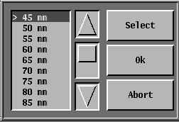
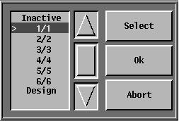
55 "Micron board" This option (initialized in the factory) permits or does not permit: - Using Electronic False Selvedge Movements (EFSM). - The CIEL board error-troubleshooting test by the micron board. - Testing the presence of fans on the Jacquard machine. - The power supply period of the electromagnets "EFSM" Access to the different fields is only possible if the "EFSM Utilisation" line (in the Micron board) has been activated previously. The micron board will then automatically detect the number of EFSM and permit access to the corresponding fields. From here, you can modify the values of the shed, phase jump and weave. The following are available: - 16 shed values by 5 mm steps (from 45 mm to 120 mm). Phase jump in relation to the cross-weaving from - 60 to types of standard weave 1/1, 2/2, 3/3, 4/4, 5/5, 6/6 and design. The programming of the EFSM is then done automatically after pressing on Apply. CAUTION When selecting the "Design" weave, you must have activated an EFSM zone in the hooking file (see corresponding paragraph). JC5 F N 55/166
56 56/166 F N JC5
57 "Jacquard maintenance" This configuration screen is only available if the Jacquard's maintenance program follow-up option is installed on the controller (see chapter "Maintenance of the JC5 controller"). This option allows you to select the type of Jacquard machine controlled by the JC5 as well as its operating environment. If your Jacquard is not indicated in the list of machine types, this means that its maintenance program is not yet available on the JC5. In this case, select the "Maintenance program deactivated" option. The machine's operating environment influences the filter changing and cleaning periods. JC5 F N 57/166

58 58/166 F N JC5
59 "Weaving record" This option permits you to choose the method for transmitting production follow-up information to the network server. The method depends on the network server and must be provided by its supplier. If there is no server, all the options must be invalidated. By default, no option is selected ex-works. JC5 F N 59/166


60 60/166 F N JC5 1
61 WEAVING MACHINE CONFIGURATION This allows you to adapt the functions of the JC5 to the weaving machine. Select the Loom icon in the Configuration option menu, then Adaptation. - "Adaptation" (preconfigured in the factory). This permits determining what type of weaving machine is associated with the Jacquard machine. - Fill in field (1). - Select the adaptation desired according to the weaving machine. - Confirm. The adaptation number is written on the wiring diagram provided with the JC5. JC5 F N 61/166

62 1 2 62/166 F N JC5
63 ADAPTATION CONFIGURATION The "Adaptation configuration" key is only present in the JC5 menu if the weaving machine is equipped with a DA40 aid device controlled by the JC5. The "Adaptation configuration" function permits visualizing and modifying the status of the aid device for the adaptation of number 053 (screen 1). The "Adaptation configuration" function permits visualizing only the status of the aid device for the adaptation of number 133 (screen 2). JC5 F N 63/166

64 64/166 F N JC5
65 SERIAL LINK / NETWORK CONFIGURATION This option allows you to operate the controller on the network and provide it with information required for the correct operation of the serial link. - "Serial link configuration" This initialises the transmission speed of the serial link between the terminal and the JC5. - Fill in each field with the transmission speeds proposed. - Confirm. - "Network configuration" Controller: Server: Username: Password: Login prompt: Enter the controller s IP address on the ETHERNET network. Enter the IP address corresponding to the server on the ETHERNET network. Enter the username defined on the server. Enter the user password defined on the server. A string of characters sent by the server during a connection request. The controller answers with a string of characters specified on the Username line. Password prompt: A string of characters sent by the server during a password request. The controller responds with a string of characters specified on the Password line. Filenames can be filtered on the controller (default value) or on the server if allowed. These parameters must be defined in collaboration with the network server supplier. JC5 F N 65/166


66 66/166 F N JC5
67 USER INTERFACE CONFIGURATION This permits customising the function keys (located on the left of the screen) as well as the screen size, if necessary. - "Keys A1 A6": This function enables the user to assign a function to each key (A1, A2, A3, A4, A5, A6) to fit his/her own specific needs. - All 6 keys are displayed on the touch pad. - Press on the key of your choice to allocate it a function. - Select the function desired. - Confirm. - Press "Save" to confirm the modification. The "Factory configuration" keypad permits restoring the initial function (ex-works) of each key. - "Panel calibration": This function allows you to readjust the touch screen's position in relation to the display. This operation must be done in case of replacing the CPU board and on reception. - Press "Panel calibration". - The screen goes black and a target appears in each corner. - Using the STAUBLI stylus supplied with the JC5, press precisely on each the black dots located in the centre of the whites circles. Doing so will recentre the screen in relation to the coordinates of the four impact points. - "Screen background": This function allows you to choose a screen background from a list of ".bmp" files. This screen is displayed instead of the main screen. This file must be in BMP format, 640 pixels wide by 480 pixels high and 16 levels of grey. JC5 F N 67/166

68 68/166 F N JC5
69 BACK-UP / RESTORE OF CONFIGURATION You can back-up the previous configuration parameters (on floppy disk) in order to retrieve them later if necessary (e.g., when changing the CPU board). This function is accessed via the MAINTENANCE icon, then the CONFIGURATION DISK. You can then retrieve this backup. We strongly recommend making this backup as soon as the configuration is satisfactory. JC5 F N 69/166


70 /166 F N JC5
71 6 - WEAVING IN PROGRESS This permits more detailed display of the design or weaving program in progress STRUCTURE WEAVING IN PROGRESS Queue Program Design Run Pick Cycle Run Pick Cycle Run Pick Cycle Display Zoom File DESCRIPTION Loom line: Program line: Run line: Pick line: Design line: Cycle line: See: gives the machine s status and its speed. gives the name of the program of the current weave. You can modify it by filling in the field and selecting a file from the list offered. This is only possible when the weaving loom is stopped. gives the number of the run in progress out of the total number of runs. gives the number of the pick in progress out of the total number of picks in a run. gives the name of the design in progress out of the weaving program in progress. gives the number of the cycle in progress out of the total number of cycles and the number of picks per cycle. permits visualising the design during weaving. Only the ZOOM and FILE functions are available. The QUIT option is under the FILE icon (see chapter "Edit a design"). The values in fields 1, 2, 3, 4 and 5 can be changed provided that their values correspond so that the weave is resumed at a specific point. The "Reset" button enables weaving to be started from the beginning: first pick of the first execution. Resetting is not possible in list mode. JC5 F N 71/166

72 /166 F N JC5
73 7 - MODIFY/EDIT A DESIGN These operations permit visualising and modifying binding points and the parameters of a design file. They are grouped under the EDIT icon of the DESIGN function. To do this, select a design in the list (1) offered PARAMETERS - Field (2): Design name. - Indicates the name of the design file and its format. - The name can be changed by pressing on it. - Field (3): Number of Picks per Cycle. - Indicates the number of picks per cycle, either as the number of picks or as the number of executions. - This field is primarily used for weaving Terry towel. The "Number of Picks" line displays the total number of picks in the design and cannot be modified from this menu. All of these parameters define the characteristics of the "current weaving" of this design. - Field (4): End of weaving. - Allows you to program automatic shutdown into the design file, either after a certain number of picks, or after a certain number of executions. - First, select "Executions" or "Picks". - Enter the desired value. - Confirm. Button (5) Attributes allows you to display and modify pattern attributes (number of rapiers,...). List (6) presents the weaving machine parameters in the pattern. These parameters are intended for the weaving machine and contain information relative to the density, warp tension or end of weaving information. Buttons (7) and (8) respectively allow selected parameters to be copied to another pattern or to deleted from the current pattern. JC5 F N 73/166

74 A B /166 F N JC5
75 7.2 - EDIT A DESIGN This permits visualising and carrying out different operations on a selected design. You can then modify the binding points from time to time via the Edit icon. The "Global Changes" option permits bigger changes regarding picks, hooks and zones. - DEFINITION OF THE ACTIVE ZONE (A) - A JC5 design can be defined in several zones. - The editor permits the display of two of these zones at the same time. - At the bottom of the touch screen, two fields (1) and (2) display the name of the corresponding zone. To display two zones: - Fill in field (2). - The list of zones composing the design being edited is displayed. - Confirm your choice. - The screen is split into two to display the two different zones. - Keys (3) and (4) permit activating the left and right zone respectively. The modifications (except those concerning the picks) and the direction of the cursor only apply to the active zone. - ZOOM This permits editing the design in the three different formats: 1st zoom: 232 hooks per 200 picks 2nd zoom: 29 hooks per 25 picks 3rd zoom: 58 hooks per 50 picks Specific modifications are not possible in the first zoom. When zooming, the window is always centred in relation to the cursor position. - EDITION (B) This permits modifying the binding points of a design. If you are working in a zone with a 2 position module, use the UP and DOWN keys to make the specific modifications. In the case of a 3 position module zone, you can use the additional MIDDLE key. The directional keypad permits automatic movement of the cursor in the direction chosen, after modification of the point. The central key permits you to cancel this effect. Other modes of moving the cursor: 1) By touching the screen at the place desired. 2) By pressing on the cursor movement zones (2) located at the bottom right of the design. 3) By filling in the "Pick" (1) and "Hook" (3) fields. JC5 F N 75/166
76 MODIFYING A DESIGN Different modification possibilities regarding picks, hooks and zones are accessible under the "Global Change" icon of the "Edit" function. The changes only concern the active zone of the design, except of course the modifications regarding the picks. They must be saved by using functions (Save, Save as) in the FILE menu. - Picks: - Copy picks (see page 77) - Delete picks (see page 78) - Vertical repetition (see page 79) - Pick duplication (see page 80) - Hooks: - Copy hooks (see page 81) - Delete hooks (see page 82) - Insert hooks (see page 83) - Hook positionning (see page 84) - Switching hooks (see page 85) - Zones: - Copy zone (see page 86) - Delete zone (see page 87) - Create zone (see page 88) - Invertions: - Invert Heavy/Light (see page 89) - Invert Left/Right (see page 90) - Invert Top/Bottom (see page 91) All these modifications take into account the type of machine modules (2 or 3 positions). 76/166 F N JC5


77 Copy picks This permits copying the binding points of one or more picks of the design by multiplying them, if required. The changes concerning the picks occur in all the zones of the design whatever the active zone on the screen. They must be saved by using functions (Save, Save as) in the FILE menu. JC5 F N 77/166

78 Delete picks This permits deleting the binding points of one or more picks of a design. The changes concerning the picks occur in all the zones of the design whatever the active zone on the screen. They must be saved by using functions (Save, Save as) in the FILE menu. 78/166 F N JC5


79 Vertical repetition This permits multiplying part of the pattern in the direction of the weft. These changes occur in the active zone. The modifications must be saved by using functions (Save, Save as) in the FILE menu. JC5 F N 79/166
 in the FILE menu. n n n.")
80 Pick duplication Pick duplication allows you to double one or more picks of the design. These changes take place at active zone level. The modifications must be saved by using functions (Save, Save as) in the FILE menu. n n n /166 F N JC5


81 Copy hooks This permits copying the binding points of a hook or a group of hooks to another hook or group of hooks of a design, if required. The changes made concerning the hooks are made in the active zone of the pattern. They must be saved by using functions (Save, Save as) in the FILE menu. JC5 F N 81/166
82 Delete hooks This permits deleting one or more hooks in a design. Deletion is done in the active zone. Deletion of all the hooks in a zone is not authorised (if necessary, use delete zone). The changes must be saved by using functions (Save, Save as) in the FILE menu. Zone 1 Zone 1 82/166 F N JC5
83 Insert hooks This permits inserting one or more hooks in a design. Insertion is done in the active zone. The changes must be saved by using functions (Save, Save as) in the FILE menu. Zone 1 Zone 1 JC5 F N 83/166

84 Hook positionning This permits modifying the binding points of part of a pattern. The changes concerning the hooks are made in the active zone of the pattern. They must be saved by using the (Save, Save as) functions of the FILE Menu. 84/166 F N JC5
 in the FILE menu. JC5 F.")
85 Switching hooks This permits switching pairs, with a repeat period, two binding points of part of a pattern. These changes are made in the active zone. The modifications must be saved by using functions (Save, Save as) in the FILE menu. JC5 F N 85/166


86 Copy zone This permits copying the binding points of a design zone into another design. The changes concerning the hooks occur in the active zone of the design. They must be saved by using functions (Save, Save as) in the FILE menu. Source file Destination file 86/166 F N JC5

87 Delete zone This permits deleting a zone in a design. Select the zone to be deleted by filling in the corresponding field. The changes must be saved by using functions (Save, Save as) in the FILE menu. Zone 1 Zone 2 Zone 1 JC5 F N 87/166
88 Create zone Permits creating a zone in a design, specifying the number of hooks, the zone no. and the type of modules (2 or 3 positions). The changes must be saved by using functions (Save, Save as) in the FILE menu. Zone 1 Zone 1 Zone 2 88/166 F N JC5
 in the FILE menu. JC5 F.140.363.")
89 Invert Heavy/Light This permits modifying the binding points of part of a pattern by transforming the raised hooks into lowered hooks and vice-versa. The changes concerning the hooks occur in the active zone of the design. They must be saved by using the functions (Save, Save as) in the FILE menu. JC5 F N 89/166
 in the FILE menu. 90/166 F.140.363.")
90 Invert Left/Right This permits modifying the binding points of part of a pattern in order to obtain symmetry around a vertical, central axis of the zone. The changes concerning the hooks occur in the active zone of the design. They must be saved by using functions (Save, Save as) in the FILE menu. 90/166 F N JC5
91 Invert Top/Bottom This permits modifying the binding points of part of a pattern in order to obtain symmetry around a horizontal, central axis of the zone. The changes concerning the hooks occur in the active zone of the design. They must be saved by using functions (Save, Save as) in the FILE menu. JC5 F N 91/166
92 C2 C1 F9 F10 F11 DC F1..F8 92/166 F N JC5
93 SPECIAL EDITORS (OPTIONS) This key allows special interpretation of a zone for a given weaving machine. IMPORTANT These editors must only be used with specific weaving machines. Before opening this special editor, all modifications currently in progress must first be saved G6200 This option can only be used if the active zone is 32 or 48 function zone. - GENERAL INFORMATION ON THE REPRESENTATION In order to represent this zone, the screen has been divided into two sections: One section represents the two colours "C1" and "C2" selected for a pick ("C1" being the first insertion, "C2" being the second in the case of a dual insertion). The other section represents the 8 general functions ("F1..F8") the density in terms of picks per centimetre ("F9"), the height of the loop in millimetres ("F10") and the relative speed in relation to the weaving machine s nominal speed ("F11"). All of these functions are displayed for the current pick ("DC"). In the case of a 32-function zone, the height of the loop and the relative speed cannot be modified as they are not considered part of the data. - COLOUR MODIFICATION Use the HIGH and LOW keys and the cursor arrow keys as with a normal editor (see "- EDITION (B)", page 75). As far as the HIGH key is concerned, the controls concerning the colours (see "- SAVE", page 97) are assigned as and when required. - MODIFICATION OF FUNCTIONS "F1..F8" Press the key located to the right of the text; the function shifts from 0 to 1 or vice versa. - MODIFICATION OF FUNCTIONS "F9" to "F11" Press the key located to the right of the text, then use the keyboard to enter a number and press the Validate key. JC5 F N 93/166
 between two destination picks. C2 FUNCTIONS FUNCTIONS C2 C2 94/166 F.140.363.")
94 - REPETITION OF COLOURS Allows WEFT direction repetition of either colour "C1" or colour "C2" or colours "C1" and "C2" of the source picks (on the basis of which buttons are selected) between two destination picks. C2 FUNCTIONS FUNCTIONS C2 C2 94/166 F N JC5
95 - PERMUTATION OF COLOURS Enables two "C1" colours or two "C2" colours or two "C1" and two "C2" colours to be swapped between the start and end picks. If one of the fields of one colour is 0 or if both fields are identical, the field is not swapped. FUNCTIONS FUNCTIONS C1 C2 JC5 F N 95/166

96 - REPETITIONS OF FUNCTIONS Enables one or several functions of a current pick ("DC") to be repeated between the two destination picks. Current pick Functions to be repeated are selected by pressing on their respective button. For selecting or deselecting all. 96/166 F N JC5
97 NOTE For all general modifications (Repetition or swapping of colours and the repetition of functions), the validity of source data and the result of the modification is checked throughout the operation. If the result is not correct, an error message indicates the faulty pick. - SAVE This key has two effects: it checks the validity of the data of the zone for all picks and saves all of the modifications carried out in this mode. Checks performed: For each pick, it checks - that the colours "C1" and "C2" are between 1 and 12, - that the colours "C1" and "C2" are different. - that the density is equal to 0 or between 5 and picks per centimetre. - that the loop height is between 0 and 20 millimetres. - that the relative speed is equal to 0 or between 50% and 100%. - RETURN Returns you to the normal editor. IMPORTANT Before returning to the normal editor, all modifications in progress must be saved OTHERWISE THEY WILL BE LOST. JC5 F N 97/166


98 1 2 A 98/166 F N JC5
99 7.3 - CONVERTING A DESIGN This permits transforming designs by using several types of available conversions. Each type requires the definition of different fields in order to constitute the conversion filter. This same transformation filter allows several transformations to be performed one after the other. Once the filter has been defined, you can use it on the design of your choice. - The types of conversion available (A) All of the pattern editor s overall modifications are available as transformation (See the Modifying a design paragraph in the Modify/edit a design chapter). Some transformations are specific to a given type of weaving machine. They enable the colours in accordance with specific formats to be encoded or decoded. The other transformations are general and are applicable to all types of weaving machines: - Doubling functions permits duplication of colours from one function to another, so as to use two bobbins of thread alternatively. The separation of functions allows a function to be distributed over several functions (between two and six). - Merging functions is the opposite operation of doubling, regrouping is the opposite of separation. - A three-position module zone is created by interlacing two two-position module zones. Each thread of the resulting zone consists of a bit taken from the first twoposition module zone and a bit taken from the second zone. Both two-position module zones must be exactly the same size. The three-position module zone replaces the first of the two source zones in the pattern; the second zone is deleted. - Creating a conversion filter - If no filter has been defined, point to field (1) then to the "New" icon. - Edit the definition of the transformation using the "Modify" button. - Complete the field (2) using the transformation types proposed in the list, then enter the information required to define the filter. - "Validate" to close the definition screen. Caution: The information must correlate with that defining the design in order to avoid errors. - The "Add" button allows an additional transformation to be created in the filter. - Save your file with the "Save as" function, then "Close". - Select the newly defined filter then confirm. - Using a conversion filter - Point to field (1) and select the filter in the list proposed. - Confirm your choice. - Select the design file to be converted. - Press on "Convert" to run the programming. - Modify an existing conversion filter - Fill in field (1) and select the filter to be modified in the list proposed. - Press on "Modify" then proceed in the same way as for creating a filter. - Confirm. JC5 F N 99/166

100 A B 100/166 F N JC5
101 7.4 - COLOUR COMPOSITION The composition of colours allows a design to be created having one single zone of 16 hooks. This design is described as a series of colour repetitions (identified by a number ranging from 1 to 16) or groups of colours. The repetitions may be nested without limitation. The composition example of screen (A) will produce the design (B). JC5 F N 101/166

102 102/166 F N JC5
103 7.5 - WEAVING MACHINE PARAMETERS The JC5 patterns can contain parameters intended for the weaving machine, such as data on density, warp tension and end of weaving. When present, these parameters are automatically transmitted to the weaving machine at the moment when weaving of the pattern starts. This possibility only exists for weaving machines equipped with a serial link. According to the type of weaving machine, "Weaving parameters" permits transferring and/or rereading these parameters. - The ">>>" key permits manual transmission of the parameters contained in the pattern being woven to the weaving machine. This function is only authorized for adaptation numbers 005, 006, 054 and The "<<<" key permits linking the current parameters of the weaving machine and it saves them in the pattern being woven. WARNING : If the pattern already contains parameters, these latter will be erased. This function is only available for adaptation numbers 005, 006, 021, 054, 055, 073, 074 and 076. The "Weaving parameters" key is not displayed in the JC5 menu unless the adaptation selected provides one of the two previous functions. JC5 F N 103/166

104 104/166 F N JC5
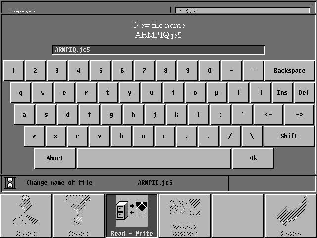
105 8 - DESIGN MANAGEMENT This icon gives access to different functions that permit you to manipulate the design files: - Import files in JC3, JC4 CGS, BMP formats and those of other companies. - Export JC5 files to other controllers. - Copy and erase files. - Read designs on a network server IMPORT A FILE By using a filter, this function enables you to convert a JC3, JC4 CGS, BMP type design file or others into a JC5 type file. For more information, see chapter "Notion of import/export filter". - Select the drive ("Disk" or "Diskette") where the file to be imported is located. - Fill-in fields "Type of designs" and "Import filter used" (the latter permits selecting and modifying an existing filter or creating a new one. - Select one of the design files proposed. - Press "import", a window is displayed. This function allows you to select the format of the design to be imported, the number of executions and the weaving machine's parameters (Fill in these different fields by using the lists proposed). It also enables the name of file to be imported to be kept or changed. If the file is imported from a JC3, JC4, JC4B or CGS diskette, the format and the number of executions cannot be modified. CAUTION The import filter used must be compatible with the information contained in the file to be converted (number of collets, number of zones to be created). JC5 F N 105/166
106 A B 106/166 F N JC5
: displays the various ranges which make up the visible zones in section (A).")
107 8.2 - CREATING AN IMPORT FILTER This function is accessed via the NEW icon. The screen has two parts: - First section (A): displays the various zones created. - Second section (B): displays the various ranges which make up the visible zones in section (A). Creating these zones allows you to isolate the various components of the design file (selvedges, functions, designs) or to copy part of the source file (JC4, CGS, etc.) into the destination file (JC5) ZONES - Fill-in field "Type" to determine whether the zone is of design type (ground, loop, selvedge) or function type (import of file.32 or.48). - Fill in the "Name" field to give a name or a comment to the zone being created RANGES - Define the values of the first range of the first zone with the MODIFY key. - Fill in fields "First thread" and "Length" in order to determine the position of the first thread of the range and the number of threads in the range. - Fill-in the "Mode" field to indicate whether the threads are imported from the left to the right ("Cont." mode) or from the right to the left ("Return mode"). - Fill in fields "Hooks taken" and "Repeat period" to define the interlacing, see chapter "Notions introduced by the JC5"). JC5 F N 107/166

108 A B 108/166 F N JC5
109 CREATING ANOTHER RANGE IN THE FIRST ZONE - The values given in the "First" and "Length" fields for the first range appear in section (B). - To create a second range, press "Add" in section (B). - Fill in the range noted ">1.2:" in the same way as before. - Perform this operation for each new range CREATING A NEW ZONE - To create a new zone, press on "Add" in part (A). - A new zone noted ">2:" appears and the ranges related to the first zone in part (B) disappear, replaced by ">2.1 :". Zone 2 1 st range - Creating this range is the same as for the first. - Use "Save as" to give a name to the filter before confirming. JC5 F N 109/166
110 110/166 F N JC5
111 8.3 - MODIFY AN IMPORT FILTER It is possible to modify a filter that exists already. - Select a filter name from the list proposed. - Press on Modify. - Place yourself in the zone and range to modified by using the arrows. - MODIFY, ADD or DELETE new zones or new ranges. Two invert two ranges or two zones, place the cursor on the zone or the range to be moved, and press on the key to place it above or on to place it below the following zone (see drawing below). JC5 F N 111/166
112 112/166 F N JC5
113 DELETE - The "Delete" key permits you to delete a filter following a previous selection or a wrong choice. CAUTION If no filter has been selected, the JC5 selects a filter by default which transfers every reading-in point from the source file into a file containing one single zone and one single range. 1 JC4 file 6144 Filter by default Zone 1 JC5 file JC5 F N 113/166


114 114/166 F N JC5
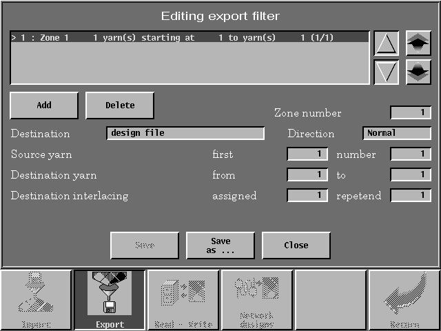
115 8.4 - EXPORT A DESIGN This function allows you to convert a JC5 design file into a JC4-compatible file. If you want to "export" a JC5 design to another JC5 you must use the "Copy" command described on page Select the design to be exported. - Fill in field "Type of design" according to the depth of the machine. - Field "Export filter used" proposes two solutions: - Use an import filter in reverse direction. - Create an export filter. In both cases, the filter and the design must be compatible regarding the number of zones and their content. USE AN IMPORT FILTER Select your import file by using key "Use an import filter", from the list proposed. CREATE AN EXPORT FILTER Use the "New" key to define your filter's parameters. The construction is the same as that for a hooking file. - The "Zone number" field displays the number of the zone from which the data will be taken. - The mode field permits determining the direction of assigning the data in the destination file: the "Cont." mode permits an assignment from the left to the right, whereas the "Return" mode permits assignment from the right to the left. - The "Destination" field permits selecting the "Design file" for the harness threads intended for a design or the "Function file" for harness threads intended for associated commands. - Fill in the "Source threads" field to determine which threads of the zone selected previously will be exported. - Field "Destination thread" gives the position of the first thread in the destination file and field "to" is calculated automatically from the data in the in the "Source thread" field. - Field "Interlacing destination" permits taking data from a starting zone which uses interlacing. Use "Add" to create a new range of threads and fill in all the fields again. Once the filter has been completed, save it by using the "Save as" function. Return to the main screen via the "Close" command, so you can select the design to be exported. JC5 F N 115/166
116 116/166 F N JC5 1
117 Once the design has been selected, simply fill-in the different fields on the screen (1) to export it. Field "Destination drive" permits choosing the medium to which the file will be sent. If choosing "Floppy disk", make sure that it is formatted in JC4 format (see chapter "Formatting a floppy disk"). Field "Format of design to be exported" permits selecting the appropriate format to the Jacquard machine. For the "Number of runs" field, value "0" corresponds to a infinite number of runs for the design. The last field is to be filled in for certain weaving looms that need to associate data concerning electric or serial link data to the design. JC5 F N 117/166


118 118/166 F N JC5
119 8.5 - COPY/RENAME/DELETE A DESIGN FILE These functions are available under the READ/WRITE icon. By selecting a file and by pressing on the question mark, you can visualise the data concerning the design. COPY: This permits copying a file from the hard disk to a floppy disk and vice versa. When the diskette contains compressed patterns, they are automatically decompressed when copied onto the hard drive. - Select the source drive (hard disk or floppy disk). - Select one or more files from the list proposed (see chapter "Selection of one or more files"). - Press on "Copy": a window is displayed. - Select the destination drive; the copy on the diskette may be compressed or not. DELETE: This permits deleting one or more files on the hard disk or on a floppy disk. - Select the drive on which the file must be deleted. - Select one or more names in the list proposed (see chapter "Selection of one or more files"). - "Delete" the file. RENAME This permits changing the name of a file. - Choose the drive (hard disk or floppy disk). - Select one or more names in the list proposed (see chapter "Selection of one or more files"). - "Rename" the old file. JC5 F N 119/166

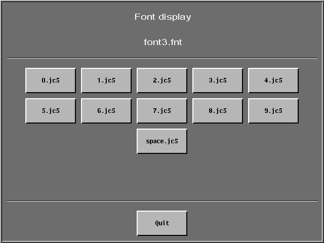
120 120/166 F N JC5
121 8.6 - READING DESIGNS ON THE NETWORK SERVER This permits the JC5 to read designs on a network server provided that the latter is equipped with software specific to this type of transfer. Your server supplier will inform you if this possibility exists. In the list, you must choose the name or names of the designs to be sent to the JC5. The "?" key permits reading data on the design (provided that the network server supplies these data). The "Confirm" key permits starting the transfer. The filter on the pattern names provides a partial list of the patterns available on the server. For example, filter A* retains only the patterns whose name begins with the letter A. This filter can be applied to the JC5 or to the server. JC5 F N 121/166


122 122/166 F N JC5
123 9 - WEAVING PROGRAM This permits creating or modifying a weaving program. For more details on this feature, refer to chapter "Notions introduced by the JC5" STRUCTURE OF THE FUNCTION WEAVING PROGRAM New Modify Delete New Group Edit group Modify group Delete Group CREATE/MODIFY A WEAVING PROGRAM NEW Element: - Select "Design" or "Group" to define the nature of the first part of the program. - For a pattern, a list of patterns on the JC5 disk is proposed. For a group, the list of groups created previously (see "Edit/create a new group") is proposed. Select your element from the list proposed. Starting picks: This parameter only exists for a pattern type element. It permits indicating that the weaving of the pattern starts on a pick other than the first. End of element after: This permits defining the end of weaving of an element being created. This end of weaving can be expressed as a number of picks or a number of runs for a pattern. It is expressed as a number of runs for a group. Add: Permits creating a 2nd part of the program (the symbol ">2:" is displayed). - Choose the type of element and define the associated parameters. - Repeat the operation to create the number of parts desired. End of program after: This permits stopping weaving after a certain number of program runs. - Press on "Save as" to save. JC5 F N 123/166


124 124/166 F N JC5
125 MODIFY - Select the weaving program to be modified. - Proceed in the same way as for creating a program in order to fill in the different fields. - Press "Save" to save the modifications EDIT/CREATE A NEW GROUP This permits creating a group on the basis of existing designs (in fact a sub-program) and visualise (or modify) its parameters. NEW GROUP Element: - Defines the nature (Design or Group) of the first part of the group. It is possible to include a group in the composition of another group. - Select the name of the design or the number of the group desired. - Enter the parameters associated with the element in the same way as in the weaving program. - Press on "Add" to insert new designs or groups. EDIT GROUP - Select one of the groups in the existing list. - Position the cursor on the part to be modified and proceed in the same way as for creating a program. To change one of the parts of the group: - Position the cursor in the part desired and point above it. - A groups or designs list is displayed. - Select the name desired. DELETE A GROUP This permits deleting an existing group by selecting it in the list proposed. JC5 F N 125/166


126 126/166 F N JC5
127 9.3 - DELETE A WEAVING PROGRAM Allows you to delete a weaving program and the designs associated with it. - Select the various designs in the list proposed. - Validate deletion of the weaving program and designs. - Confirm by pressing the Yes key. JC5 F N 127/166

128 /166 F N JC5
129 10 - AUTOMATIC NUMBERING FILE (OPTION F ) Enables an automatic numbering file to be created or modified. An automatic numbering file allows various independent counters to be defined to identify items in a pattern. Each counter has its own incrementation rules FUNCTION STRUCTURE AUTOMATIC NUMBERING New Modify New Counters Edit Counters CREATE/MODIFY AN AUTOMATIC NUMBERING FILE PATTERN Pattern (1): - Select the pattern to be woven. Nbr Exec (2): - Enter the number of pattern executions (0 corresponds to an infinite execution number). ADD/DELETE Add: - Add a counter. Delete: - Deletes the counter selected. JC5 F N 129/166

130 /166 F N JC5
131 COUNTER Counter name (1): Enables the name of the counter to be defined. When a counter is created, the default name is "counter x". Number in X: Allows the counter's repetition number to be defined in the width of the pattern. Font: Allows the font used for this counter to be selected. If "NO FONT" is selected, the "default.fnt" font will be used during weaving. Nbr characters: This is used to define the number of characters used for the weaving of this counter. If its value is 0, the "Style" field is not used and the number of characters will be determined by the value of the counter. If the value of the "Number of characters" field is less than the number of characters of the counter, the counter will be truncated to the value of the "Number of characters" field. For example, the value 1004 with the "Number of characters" field initialised at 3, number "004" will be woven whether the style is space or zero. Style: Allows to define if spaces or 0 (zeros) are inserted to complete the counter to the number of characters defined in the "Number of characters" field, if it is other than 0. Orientation: Enables the write direction of the counter to be defined. Pattern zone: This allows you to define the zone of the pattern where the counter will be inserted. The hook number information of the counter's definition is related to the hooks in this zone. Counter position and values: - Field (7) is used to define the counter's initial value. - If the "Number in X" field (9) is greater than 1, field (8) allows you to define the second value of the counter in the pattern width. The increment between fields (8) and (9) is used for the X counter repetitions in the pattern's width. - Field (2) defines the value of the counter during the second execution of the pattern. The increment between fields (5) and (2) is used for each pattern execution. - Field (6) defines the hook of the zone considered in the pattern (10) used as the first hook of the counter. - If the "Number in X" field (9) is greater than 1, field (7) allows you to define an offset in hooks between 2 counters in the pattern width. - Field (4) defines the pick of the pattern used as the first pick of the counter. - Field (3) indicates the number of picks in the pattern. JC5 F N 131/166


132 132/166 F N JC5
133 FONTS: The font selection screen also allows you to create, delete and view a font. When creating a font, the positions and sizes of the font's various patterns are saved. In the creation screen, simply select an existing font and the position and size values are recovered. In order to crate a new font, the name of the font and the name of the pattern from where the font will be extracted must be modified. JC5 F N 133/166


134 /166 F N JC5
135 11 - WEAVING LIST This weaving option is added to the pattern and program modes. Access is gained only via the weaving change function. Procedure: Select the list button (1) and the Weaving List screen appears. Complete list management is controlled via this screen. The required information is as follows: - The filename. - The operating mode: pick (a defined quantity of picks will be woven). execution (execution of a whole number of repetitions of the file). - The number of executions or picks programmed. - The starting pick in the pattern. The above parameters are displayed as well as a file status indicator (free or locked). The list may be modified at any time by either adding, deleting or swapping patterns ADD AN ELEMENT TO THE LIST + key A selection screen appears. select the following parameters: - The pattern to be inserted. - The operating mode: pick or execution. - The number of executions or picks. - The starting pick. Confirm or cancel using the Validate or Cancel keys DELETE AN ELEMENT - key - Select the pattern to be deleted with the cursor. - Delete the element with the key SWAP TWO ELEMENTS Use the selection arrows (2) - the swap is made between the selected pattern and the preceding or the following pattern. JC5 F N 135/166
136 136/166 F N JC5
137 CLOSE WEAVING Deselection of files currently being weaved WEAVING CHANGE Return to the program or pattern modes VALIDATE This key activates the list mode. It is available only when in list mode (the key is present if the list mode is not validated) CANCEL This key allows you to leave the application without changing the weaving mode (the key is present if the list mode is not validated) CLOSE This key allows you to leave the list screen (key present if the list mode is validated). JC5 F N 137/166
138 /166 F N JC5
139 12 - MAINTENANCE OF THE JC5 CONTROLLER It permits carrying out tests on the different devices of the Jacquard machine, to check its correct operation, and to access the controller configuration CREATING A DESIGN TEST The pick of this design test replaces the pick of the weaving in progress, when pressing the weaving key. This file is interpreted as a design file of a single pick by the machine but it is not woven. This permits detecting and localizing breakdowns in the operation of the hooks by activating them one by one. Normal weaving is restarted on quitting the application. - Description of the screen and functions: - The plan of the modules appears in the upper left-hand corner of the screen (1). - By default, the module selected is the first module of the first line. - Windows (2) is a zoom of the module selected and the eight boxes correspond to the module's eight harness cords. - To displace the selection frame (3), press directly on the module desired or use the direction arrows on the front panel. - Window (2) changes to reflect the new frame selected. - The maximum number of ribbons which can be displayed on the screen is The maximum number of lines is 32. The and keys allow you to display the modules controlled by the various CICOs. A CICO board controls a maximum of 12 ribbons on 32 modules lines. - Example: Jacquard machine configuration: hooks by 32 (in depth). By default, window (1) displays the ribbons controlled by CICO 1 (harness cords 1 through 3072). Press. - The window displays the ribbons controlled by CICO no. 2 (harness cords 3073 to 6144). - Pressing again displays the next and so on. - The keys and are used when the JC5 is connected to several Jacquard machines. JC5 F N 139/166


140 /166 F N JC5
141 - Creating a design test: - assign the upper or lower position, - either to lines, - either to the ribbons, - either to the modules, - either to the harness cords of the module, by pressing directly in the window (1), - either to all modules controlled by a CICO, - or to the entire machine (3). - The module's number as well as the number of the line and the ribbon where it is located is defined by the position of the selection frame (2). - Next Confirm your design test; then start with the Weaving program. JC5 F N 141/166
142 /166 F N JC5
143 TEMPERATURE MEASUREMENT IN THE JACQUARD MACHINE Certain Jacquard machines are equipped with a temperature sensor. The screen permits displaying the results of measurements made periodically (one per hour). The first screen presents, for each of the Jacquard machines connected to the JC5: - the current temperature (1), - the maximum temperature (4). The calculation period for the maximum temperature is chosen in field (2). This period can extend to one week, a month or to the entire measurement capacity of the JC5. The History (3) key permits visualisation of all the measurement archives. JC5 F N 143/166

144 /166 F N JC5
145 This screen presents the temperature measurement history. The keys (3) permit modifying the value of the zoom on the time scale. The values possible are: - a sample per hour (value displayed when entering the screen), - a sample per day (the value displayed is the maximum temperature of the day), - a sample per month (the value displayed is the maximum temperature for the month). The <next page> and <previous page> keys (2) permit moving in the pages of the history. The arrows external to the screen permit moving the cursor (1). The value of the sample under the cursor is displayed below the curve (4). The small symbols on the curve indicate the restoring of power to the JC5 (symbol 6) and the resetting of the time of the JC5 (symbol 5). Field (7) permits choosing the Jacquard machine for which you want to visualise the history. JC5 F N 145/166


146 146/166 F N JC5
147 TESTING THE JC5 This permits testing the Inputs/Outputs board as well as the disk drive. - Inputs/Outputs test: - A window is displayed with squares symbolising the inputs and outputs. - A small lamp inside a square corresponds to an active signal. - The outputs can be forced to zero or one, by pressing directly on the corresponding square. Caution: the test leaves the outputs in their modified status. - Floppy disk test: This permits testing the floppy disk drive. - Insert the floppy disk. - Press on "Floppy disk test". - Confirm the test by pressing on "Yes". CAUTION All the data on the floppy disk are erased during this test. JC5 F N 147/166


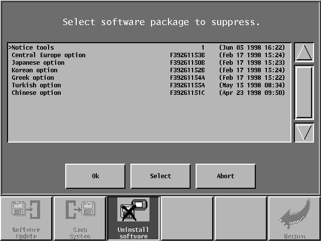
148 148/166 F N JC5
149 SYSTEM DISK This permits loading, reinitialising, saving and deletion of a software version. - Updating the software: This permits loading a new version of the software or rebooting the controller after an incident. This function also permits loading optional software modules. Updating the software takes about forty seconds. Wait until returning to the main screen before using the touch screen. - System backup: This permits creating a system disk to backup the microprocessor software. Choose the file to be saved from the list proposed. Note that this operation can take several minutes. - Software deletion: This permits deleting a software module. Only the optional modules can be deleted VERSION This informs you of the version of the softwares installed in the JC5, with the possibility of seeing the modifications and saving them. JC5 F N 149/166


150 /166 F N JC5
151 13 - JACQUARD MAINTENANCE PROGRAM The JC5 can automatically manage the Jacquard machine's maintenance program. This maintenance program is optional and is not available on all Jacquard machines. When a maintenance operation must be performed on the Jacquard, an information screen appears on the JC5. This screen provides a graphic representation of what operation is to be performed. The user then has the choice of performing the operation at a later date (1) or to carry it out immediately (2). In the latter case, the user must identify himself in the maintenance program's history record. When a maintenance operation is postponed, the consequences are as follows: - an icon flashes on the JC5's main screen alternately with the JC5 and Jacquard machine synchronisation icon. Pressing this icon displays the description of the maintenance operation to be performed. When no maintenance operations are scheduled, pressing this icon will display the maintenance program's history record. - the maintenance operation description screen is displayed each time the JC5 is powered up and following each weaving machine shutdown lasting more than 5 minutes. - the weaving machine cannot restart while the maintenance operation description screen is displayed MAINTENANCE PROGRAM HISTORY RECORD The maintenance program history provides a list of the operations already performed (3) and a list of future operations (4) to be conducted. For both lists, the "Detail" button allows you to view the description of the operation selected. For the list of future operations, a maintenance operation can thus be anticipated and performed before its deadline. The following information is provided for each operation carried out: - the date on which the operation was scheduled as well as the number of picks and corresponding operating hours. - the date on which the operation was actually performed as well as the number of picks and corresponding operation hours. - the name of the person who performed the maintenance operation. The list of future operations indicates the foreseen deadline of each operation. This deadline may be expressed as a date, the number of picks woven, the number of operating hours or as a combination of these three elements. The current date as well as pick and operating hour meters are indicated at the top of the history screen (5). The maintenance program history may be saved to a diskette in the form of a tabulated text file. JC5 F N 151/166


152 152/166 F N JC5
153 14 - UTILITIES This permits managing files (copy, rename, etc.), using the calculator and converting the controller into a terminal TERMINAL A maintenance terminal is displayed on the JC5 screen. This terminal must only be used by qualified Stäubli personnel SERVER TERMINAL Here, the JC5 is used as a terminal of the server network. Ask your network supplier for advice to determine whether the server can use this function FILE MANAGEMENT This permits carrying out write, read, erase and rename operations for files on the hard disk or floppy disk and the network to read the server files. - Copy - Choose the home drive. - Select the file(s) to be copied in the list presented. - Choose the destination drive by using the COPY icon. - Erase (only hard disk and floppy disk) - Select the drive containing the file to be erased. - Select the name(s) to be erased and point to "Erase". - Confirm your request. - Rename (only hard disk and floppy disk) - Choose the home drive. - Select the name(s) to be renamed in the list presented. - "Rename" them by using the alphanumeric keyboard CALCULATOR This gives access to a four operation calculator comprising different basic functions: - A few basic functions: BS key (Backspace): STO key (Store): RCL key (Recall): DEL key (Delete): This permits erasing the last character typed. This permits memorising a result or a figure. The contents of the memory are displayed opposite "Memory". This permits recalling the contents of the memory to the screen. This permits erasing a character after selecting it with the arrows. JC5 F N 153/166

154 154/166 F N JC5
155 15 - SPY This option permits archiving different files that reflect events occurring during weaving, for example, on the serial link or on inputs. These files are permanently updated, as soon as an event occurs. It is thus possible to save them on a floppy disk when a weaving problem happens, in order to facilitate finding the problem. This operation must be done immediately after a fault is detected, since, when the machine is running, the recordings are made constantly, with the old data being replaced by the most recent. - Select the spy file(s) to be archived. This operation is optional. - "Archive" (Start this step if you want to archive all the files). - Select file "record.gz". - Copy it on a floppy disk. - Send the floppy disk to STÄUBLI Faverges. In the factory configuration, key A5 (located on the front panel), permits direct access to this function (see chapter "Configuration") and saving all the spy files on the hard disk (compressed in file "Record.gz"), then on a floppy disk. By pressing on the "Current" button, you can stop the spy monitoring function. The button changes to "Stop" status. You simply need to press this key again or cut off the power to the JC5 to reactivate the function. JC5 F N 155/166
156 156/166 F N JC5 2
157 16 - SECURITY This menu permits customising access rights to different functions, according to one of the four security levels. Thus, according to your choice, you can limit, in varying degrees, the possibilities for modifying the different fields of each function. Pressing on a non-authorised function icon or field (identified by a padlock (2)) will therefore have no effect CHOICE OF SECURITY LEVEL Fill in field "Current Security Level", by choosing the level: Super user Modification Save Weaving CAUTION Before any change of level, make a "super user" level floppy disk (see next chapter). This key disk will permit retrieving all the access authorisation when you want to change from a lower security level to a higher one. The number of prohibited functions increases the further down the list from "Super user". The prohibited functions are marked by a small padlock (2). Level changes may be made freely from Super User to Basic weaving. However, a system disk is required to advance to the next higher level in the opposite direction. 1 Super user 1 Super user Free 2 Modify 2 Modify Free 3 File saving 3 File saving Free 4 Basic weaving 4 Basic weaving FREE KEY FLOPPY DISK JC5 F N 157/166

158 158/166 F N JC5
Tutorial. COPYRIGHT 2014 IGE+XAO. All rights reserved TUTORIAL. Your first steps with SEE Electrical Expert. The specialist of electrical software
 TUTORIAL Your first steps with SEE Electrical Expert The specialist of electrical software Page 2 A.1. Conventions used in this tutorial TABLE OF CONTENTS A OVERVIEW... 5 A.1. CONVENTIONS USED IN THIS
Table of Contents. Introduction 2 1. Intelligent Remote Control 2 2. Charging the Remote Control 3
 Table of Contents Introduction 2 1. Intelligent Remote Control 2 2. Charging the Remote Control 3 Getting Started 6 1. Activating the Remote Control 6 2. Selecting a Device 7 3. Operating a Device 8 4.
Mark III Series Full-Function Models
 English Mark III Series Full-Function Models (B) Advanced Operation Manual English Table of Contents Advanced Playback Chapter 1 Storing & Managing Songs on Disks Using Memory Disks... 1 Specifying a
Operating Instructions / User manual. IRSoft. Version 2.0. Documentation software for ERSA Rework Systems. ERSA GmbH
 Operating Instructions / User manual IRSoft Version 2.0 Documentation software for ERSA Rework Systems ERSA GmbH Wertheim / Main July 2002 ERSA has taken great care in the preparation of this Users Guide,
ArahWeave Jacquard Quick Start
 ArahWeave Jacquard Quick Start C O N TE N TS YO U W I L L L E A R N H O W TO : CONVERT AN IMAGE INTO A JACQUARD WEAVE 3 D E F I N E W E A VE S F O R E A C H C O L O R IN THE IMAGE 3 CONSTRUCT A JACQUARD
Upgrade Instructions. View Manager 96 v Software Upgrade. The system displays the following prompt:
 WORLD LEADER IN ELECTRONIC SECURITY Upgrade Instructions View Manager 96 v. 5.0 1 Software Upgrade This software permits you to upgrade your VM96 version 3.x or 4.x system to the latest version of VM96
DAUMAR 40 Windows 95 software for labeling machines
 DAUMAR 40 Windows 95 software for labeling machines Version 050199 1 IMPORTANT NOTICE ABOUT HOW TO INSTALL DE DAUMAR 40R 2.41 The Daumar 40 R.2.41 Version is prepared for working with Windows 95 and 98
ATMOS Capture Suite. Operating Instructions. English. These operating instructions are valid from software version 4.0. GA1GB
 Operating Instructions ATMOS Capture Suite English These operating instructions are valid from software version 4.0. GAGB.500.0 08- Index 0 Table of contents Introduction...4. Notes on operating instructions...4.
5. LAPTOP PROCEDURES
 5. LAPTOP PROCEDURES Introduction This next section of the user guide will identify core essentials regarding your laptop turning it on, running the program, running the questionnaire, submitting the data,
ProntoPro Intelligent Remote Control. User Guide
 ProntoPro Intelligent Remote Control User Guide Table of Content Taking a First Look... 3 Intelligent Remote Control... 3 Before You Start... 5 Getting Started... 7 Activating the Remote Control... 7 Defining
USER MANUAL. TL400B Fingerprint Lock with Voice Guide Feature. Version: 1.1 Date: Jul. 2017
 USER MANUAL TL400B Fingerprint Lock with Voice Guide Feature Version: 1.1 Date: Jul. 2017 1 Content Read Before Use 1 Safety Caution 1 Structure 2 Basic Function 3 User Introduction 3 Operation and Voice
Copyright 2004, Mighty Computer Services
 EZ-GRAPH DATABASE PROGRAM MANUAL Copyright 2004, Mighty Computer Services The Table of Contents is located at the end of this document. I. Purpose EZ-Graph Database makes it easy to draw and maintain basic
Dryer. M720 Programming and Operation Manual. July 15, 2015 Revision 1.51
 Dryer M720 Programming and Operation Manual July 15, 2015 Revision 1.51 Contents 1 Important Safety Information 1 1.1 FOR YOUR SAFETY - CAUTION!............................. 1 2 Control Overview 2 2.1
Technical support and product information. LAE electronic TAB4.
 User s guide Technical support and product information http://www.lae-electronic.com/ info@lae-electronic.com Page 2 LAE electronic TAB4.2 - User s guide TAB 4.2 - User s guide INTRODUCTION TAB is a software
Table of Contents. Taking a First Look 2 Intelligent Remote Control 2 Before You Start 4
 Table of Contents Taking a First Look 2 Intelligent Remote Control 2 Before You Start 4 Getting Started 6 Activating the Remote Control 6 Defining the Brands of Your Devices 7 Working with the Home Panel
A new clients guide to: Activating a new Studio 3.0 Account Creating a Photo Album Starting a Project Submitting a Project Publishing Tips
 Getting Started With Heritage Makers A Guide to the Heritage Studio 3.0 Drag and Drop Publishing System presented by Heritage Makers A new clients guide to: Activating a new Studio 3.0 Account Creating
NOTE_BOX_009 ELCO INFRARED KEYPAD USER S HANDBOOK. Divisione. S.r.l. USER S HANDBOOK INFRARED KEYPAD NOTE_BOX_009 File: MN INGL.
 1/23 2/23 INDEX NORMS AND GENERAL WARNING 3 KEYPAD S EXTERNAL DESCRIPTION 4 OPERATIVE FUNCTIONS 6 Address to control boxes 6 Broadcast and Compound address 8 Main Menu 9 Manual function 11 Reception of
IDEA. User s Guide. Part No IDE02 Issue 1-0, April 1995 Printed in U.S.A. (183)
") IDEA User s Guide Part No. 17500IDE02 Issue 1-0, April 1995 Printed in U.S.A. (183) 4 FOREST PARKWAY, SHELTON, CONNECTICUT 06484 TEL: 203-926-5400 FAX: 203-929-0535 This manual has been developed by Nitsuko
IDEA User s Guide Part No. 17500IDE02 Issue 1-0, April 1995 Printed in U.S.A. (183) 4 FOREST PARKWAY, SHELTON, CONNECTICUT 06484 TEL: 203-926-5400 FAX: 203-929-0535 This manual has been developed by Nitsuko
Woven design data transmission using TTL logic for 128 hooks electronic cardless jacquard
 Indian Journal of Fibre & Textile Research Vol. 40, March 2015, pp. 100-104 Woven design data transmission using TTL logic for 128 hooks electronic cardless jacquard R Kumaravelu 1,a, S Poornima 1 & N
CROMWELLSTUDIOS. Content Management System Instruction Manual V1. Content Management System. V1
 Content Management System Instruction Manual V1 www.cromwellstudios.co.uk Cromwell Studios Web Services Content Management System Manual Part 1 Content Management is the system by which you can change
Guidelines for lesson creation [with basic topics to be covered] (1-1, 1-2) Parts of a computer and identifying
![Guidelines for lesson creation [with basic topics to be covered] (1-1, 1-2) Parts of a computer and identifying](/thumbs/79/80086228.jpg "Guidelines for lesson creation [with basic topics to be covered] (1-1, 1-2) Parts of a computer and identifying") Guidelines for lesson creation [with basic topics to be covered] (1-1, 1-2) Parts of a computer and identifying What minimal topics must to be covered in each lesson? List only the 4 main parts of a computer
Guidelines for lesson creation [with basic topics to be covered] (1-1, 1-2) Parts of a computer and identifying What minimal topics must to be covered in each lesson? List only the 4 main parts of a computer
EATON 5S 850/1200/1600
 www.eaton.com EATON 5S 850/1200/1600 Installation and user manual Packaging EATON 5S 1 2 3 5 Caution! l Before installing the Eaton 5S, read the booklet 3 containing the safety instructions to be respected.
 INTRODUCTION This controller is suitable for controlling up to twenty four (24) DMX-512 units of any type with maximum 32 channels respectively (scanner, moving head, strobe, etc). The controller s software
Software User s Manual
 1 About the manual 2 Navigating the manual 2 3 Opening the control panel 3 Control panel overview 4 Control panel settings 5 Calibrating the interactive pen display 6 Adjusting frequency and tracking (VGA
Functional Skills. Entry 3 to Level 2. IT Basics Information
 Functional Skills Skills ICT Entry 3 to Level 2 YOU DO NOT NEED TO WORK THROUGH THIS. IT IS AN PACK TO TEACH YOU THE SKILLS NEEDED TO COMPLETE THE TASKS. YOU CAN USE IT WHILST WORKING THROUGH THE TASKS,
Product RS stock no. Mitsubishi no. Description and features Display FX-40DU-E LCD display and function keys directly connected into FX PLC
 Data Pack D Issued March 1997 232-6118 Data Sheet Man machine interface display Mitsubishi FX PLC Supplied to RS by Mitsubishi Electric (UK) Ltd This fully interactive man machine interface display is
Show Designer 1. Software Revision 3.11
 Show Designer 1 Software Revision 3.11 OVERVIEW The Show Designer 1 is a lighting controller based on the successful and simple to use Show Designer. The Show Designer 1 adds to the existing features of
Axxis Biometrics LLC. BioAxxis L113 Fingerprint Door Lock Programming Kit
 Axxis Biometrics LLC BioAxxis L113 Fingerprint Door Lock Programming Kit Revision 0.14 Dec 2005 Table of Contents 1. Introduction... 2 Product Overview... 2 Main Features... 2 Packing Lists... 3 2. Operation
SOFTWARE KR C... User Programming. KUKA System Software (KSS) Release 4.1. Issued: 14 Jul 2003 Version: 03. ProgAnwenderR en.
 Release 4.1. Issued: 14 Jul 2003 Version: 03. ProgAnwenderR en.") SOFTWARE KR C... User Programming KUKA System Software (KSS) Release 4.1 Issued: 14 Jul 2003 Version: 03 1of 60 e Copyright KUKA Roboter GmbH This documentation or excerpts therefrom may not be reproduced
SOFTWARE KR C... User Programming KUKA System Software (KSS) Release 4.1 Issued: 14 Jul 2003 Version: 03 1of 60 e Copyright KUKA Roboter GmbH This documentation or excerpts therefrom may not be reproduced
Model High -Tech Programmable Controller. Operating Instructions
 Model High -Tech Programmable Controller Operating Instructions Version 2 Yamato Scientific Co., Ltd 1.. INTRODUCTION...... 2 Explanation of Character on the display.........3 2. INPUTTING, EDITION AND
Pronto. User Guide. User Guide
 Pronto EN 1 Pronto Copyright 2005 Royal Philips Electronics, Interleuvenlaan 72-74, 3000 Leuven (Belgium) Remark: All rights are reserved. Reproduction in whole or in part is prohibited without prior consent
Avigilon Control Center Web Client User Guide
 Avigilon Control Center Web Client User Guide Version: 4.12 Standard PDF-WEBCLIENT-S-E-Rev2 Copyright 2013 Avigilon. All rights reserved. The information presented is subject to change without notice.
Digital Display Wall Application Management Software
 VWAS6.0 日常使用手册 Digital Display Wall Application Management Software VWAS6.0/VCMS/VEMS User Manual Copyright Statement This manual is the copyright property of VTRON. Without prior written approval from
4 The Strategy Builder
 4 The Strategy Builder This chapter describes Strategy Builder operation and how to set up a PC-30 strategy. As described earlier in Chapter 1: Introduction, a PC-30 strategy consists of Algorithms you
USER S MANUAL VERSION: #1.0. EBS Ink-Jet Systeme GmbH. Alte Ziegelei 19-25, D Nümbrecht. +49 (0)2293 / Fax +49 (0)2293 / 939-3
2293 / Fax +49 (0)2293 / 939-3") T200 TERMINAL USER S MANUAL VERSION: 20080129#1.0 EBS Ink-Jet Systeme GmbH Alte Ziegelei 19-25, D-51588 Nümbrecht +49 (0)2293 / 939-0 Fax +49 (0)2293 / 939-3 http://www.ebs-inkjet.de 2008 EBS Ink-Jet Systeme
T200 TERMINAL USER S MANUAL VERSION: 20080129#1.0 EBS Ink-Jet Systeme GmbH Alte Ziegelei 19-25, D-51588 Nümbrecht +49 (0)2293 / 939-0 Fax +49 (0)2293 / 939-3 http://www.ebs-inkjet.de 2008 EBS Ink-Jet Systeme
Pace Clock. For the System 6 Sports Timer Software User Guide. F873 rev
 Pace Clock For the System 6 Sports Timer Software User Guide F873 rev 20171114 Customer Service Department www.coloradotime.com Email: customerservice@coloradotime.com Phone: +1 970-667-1000 Toll Free
FC-11 FIELD COMMUNICATOR 1.54 INSTRUCTION MANUAL. IM-EN-FC11 Version 1.13
 FC-11 FIELD COMMUNICATOR 1.54 INSTRUCTION MANUAL IM-EN-FC11 Version 1.13 Table of contents 1 Description............................................................ 1 1.1 Kit contents....................................................
Operator terminals. Dialog 80 and Dialog 640 User guide
 Operator terminals Dialog 80 and Dialog 640 User guide SERAD SA 271, route des crêtes 44440 TEILLE France +33 (0)2 40 97 24 54 +33 (0)2 40 97 27 04 http://www.serad.fr info@serad.fr TD-UM/EN SERAD reserves
Figure 1: NC > 2 Axis menu > Options
 Click To See: How to Use Online Documents SURFCAM Online Documents J 685)&$0Ã5HIHUHQFHÃ0DQXDO 7 &21),*85$7,21722/6 7.1 INTRODUCTION SURFCAM s default configuration parameters are contained in the SURFCAM.INI
Facial & Fingerprint Recognition Product
 Facial & Fingerprint Recognition Product Series User Manual Version: 1.1.7 Date: January 2010 About This Manual This document introduces the user interface and menu operations of the Facial & Fingerprint
U90 Ladder Software Manual. Version 3.50, 6/03
 U90 Ladder Software Manual Version 3.50, 6/03 Table Of Contents Welcome to U90 Ladder... 1 Program Editors... 1 Project Navigation Tree...1 Browse Sequences...1 Printing Documentation...2 Interface Language...
AVL Compu-Dobby Loom Control. with. WeavePoint 7. User's Guide. Copyright AVL Looms, Inc/B.T. Myhre All rights reserved
 AVL Compu-Dobby Loom Control with WeavePoint 7 User's Guide Copyright 1998-2011 AVL Looms, Inc/B.T. Myhre All rights reserved www.avlusa.com AVL Looms, Inc. WEAVE MENU Weave Menu items will allow you to
SISpro building 2.1. User's reference manual
 SISpro building 2.1 User's reference manual SISpro building 2.1 Page 2 Contents Overview....5. Project step....13. Design step....17. Single line diagram step....191. Quotation step....195. Order form
GAMMA instabus Application Program Description. July CO Colour Touch-Panel
 Use of the application program Product family: Product type: Manufacturer: Name: Order no.: Name: Order no.: Display Display units Siemens UP 588/12 Colour Touch Panel UP 588/13 Colour Touch Panel (AC
ASIC-200 Version 5.0. integrated industrial control software. HMI Guide
 ASIC-200 Version 5.0 integrated industrial control software HMI Guide Revision Description Date C Name change, correct where applicable with document 4/07 HMI Guide: 139168(C) Published by: Pro-face 750
ProCASE II User Manual
 ProCASE II User Manual 270 Rutledge Road, Fletcher, NC 28732 USA (800) 233-0580 (828) 654-7920 Fax (828) 654-8824 The contents of this document are protected under the copyright laws of the United States
DPS900 SOFTWARE QUICK REFERENCE CARD FOR PILING OPERATORS
 DPS900 SOFTWARE QUICK REFERENCE CARD FOR PILING OPERATORS This document contains information for piling operators on how to use the Trimble DPS900 software. For information for supervisors, please refer
Getting Started Tutorial
 Getting Started Tutorial V8R1 Copyright Copyright (c) May 2015 IGE-XAO. All rights reserved. No part of this manual, or any portion of it, shall be reproduced, transcribed, saved or translated, under whatever
Using MDC Manager to Manage Power Settings
 AddendumA Using MDC Manager to Manage Power Settings This addendum explains how to use the MDC Manager to configure and manage the power settings for the M7. It is organized into the following sections:
LCD MONITOR TOUCH PANEL DRIVER OPERATION MANUAL. for Mac. Version 1.0 PN-L802B/PN-L702B/PN-L602B. Applicable models
 LCD MONITOR TOUCH PANEL DRIVER OPERATION MANUAL for Mac Version 1.0 Applicable models PN-L802B/PN-L702B/PN-L602B Contents Introduction...3 System Requirements...3 Setting up the Computer...4 Installing
TOF-Watch SX Monitor
 TOF-Watch SX Monitor User manual Version 1.2 Organon (Ireland) Ltd. Drynam Road Swords Co. Dublin Ireland Contents General information... 3 Getting started... 3 File Window... 7 File Menu... 10 File Open
Android (A1000) Y4 Classrooms: User Guide
 Y4 Classrooms: User Guide") Android (A1000) Y4 Classrooms: User Guide Provided by the SDUSD Ed Tech Team i21 2014 Teachers - Version 3.25.2014 Table of Contents Basic Functionality... Navigation Tips... Taking a Screenshot... Finding
Android (A1000) Y4 Classrooms: User Guide Provided by the SDUSD Ed Tech Team i21 2014 Teachers - Version 3.25.2014 Table of Contents Basic Functionality... Navigation Tips... Taking a Screenshot... Finding
Ariel Dynamics, Inc. TRIM MODULE. Revision 1.0. Ariel Dynamics, Inc. C3D TRANSFORM MODULE
 Ariel Dynamics, Inc. TRIM MODULE Revision 1.0 Ariel Dynamics, Inc. C3D TRANSFORM MODULE Contents i Contents ARIEL TRIM PROGRAM 1 INTRODUCTION...1 WHAT S NEW IN TRIM 1.0...1 SYSTEM REQUIREMENTS...2 TO START
Using the Computer & Managing Files Part 2
 Using the Computer & Managing Files Part 2 Using the Computer & Managing Files...65 Example 1 File compression, or zipping...66 Exercise 1 Download and install software...66 Exercise 2 Understand file
DCN Next Generation Intercom. en Software User Manual LBB 4173/00
 DCN Next Generation Intercom en Software User Manual LBB 4173/00 About this manual This user manual is divided into five chapters. Chapters 1 and 2 provide background information and chapters 3 and 4 provide
VIMED JWEB Manual. Victorian Stroke Telemedicine. Version: 1.0. Created by: Grant Stephens. Page 1 of 17
 VIMED JWEB Manual Victorian Stroke Telemedicine Version: 1.0 Created by: Grant Stephens Page 1 of 17 1 Table of Contents 1 Table of Contents... 2 2 What is JWEB?... 4 3 Accessing JWEB... 4 3.1 For Mac
Océ Engineering Exec. Electronic Job Ticket
 Océ Engineering Exec Electronic Job Ticket Océ-Technologies B.V. Copyright 2004, Océ-Technologies B.V. Venlo, The Netherlands All rights reserved. No part of this work may be reproduced, copied, adapted,
CardMaster Programming Guide Rev CardMaster Operators Guide. CardMaster Installation Manual. CardMaster Service Guide
 CardMaster Programming Guide Rev 10.06.03 Related Manuals include: CardMaster Operators Guide CardMaster Installation Manual CardMaster Service Guide CardMaster RF Installation Manual Wireless Modem Setup
Libraries. Multi-Touch. Aero Peek. Sema Foundation 10 Classes 2 nd Exam Review ICT Department 5/22/ Lesson - 15
 10 Classes 2 nd Exam Review Lesson - 15 Introduction Windows 7, previous version of the latest version (Windows 8.1) of Microsoft Windows, was produced for use on personal computers, including home and
CP-WU5500/CP-WX5500/CP-X5550 CP-WU5505/CP-WX5505/CP-X5555
 LCD Projector CP-WU5500/CP-WX5500/CP-X5550 CP-WU5505/CP-WX5505/CP-X5555 User's Manual (detailed) Instant Stack Guide Thank you for purchasing this product. Features This projector can be used with another
Ishida Label Editor USER GUIDE
 Ishida Label Editor USER GUIDE ISHIDA CO., LTD Copyright 2000 Ishida Co. Ltd., Japan Copyright 2000 Interface Translation Ltd., New Zealand No part of this manual may be reproduced or transmitted in any
ActivPanel. User Guide for Staff. Produced by C&IT Services
 ActivPanel User Guide for Staff Produced by C&IT Services TABLE OF CONTENTS TABLE OF CONTENTS... 2 OVERVIEW... 4 1.0 WHERE CAN I USE ACTIVPANEL?... 4 2.0 THE ACTIVPANEL COMPONENTS... 5 2.1 THE LCD TABLET...
ArtDMX DMX control software V1.4
 User manual ArtDMX DMX control software V1.4 1 2 Table of contents : 1. How to start a new Project...6 1.1. Introduction...6 1.2. System Requirements...6 1.3. Installing software and drivers...7 1.4. Software
Document History. 2.0 July February 2007
 CompuDIM 2000 Reference Guide CompuDim 2000 Copyright 2007 Compulite Systems (2000) Ltd. All rights reserved. This documentation is delivered subject to the following conditions and restrictions: This
COMPUTER DESCRIPTION...
 Conventions used in this document: Keyboard keys that must be pressed will be shown as Enter or Ctrl. Controls to be activated with the mouse will be shown as Start button > Settings > System > About.
StepPolyArp Unit. Step Polyphonic Arpeggiator / Sequencer App & Audio Unit MIDI effect for ios
 StepPolyArp Unit Step Polyphonic Arpeggiator / Sequencer App & Audio Unit MIDI effect for ios Presentation... 1 Application setup... 2 MIDI connections between ios applications... 2 MIDI over WiFi on macos...
HP Notebook PCs - Keyboard and TouchPad or ClickPad Guided Troubleshooter
 HP Notebook PCs - Keyboard and TouchPad or ClickPad Guided Troubleshooter This document applies to HP notebook computers. The keyboard, TouchPad, or ClickPad on your laptop is not working as expected:
LME Software Block Quick Reference 1. Common Palette
 LME Software Block Quick Reference Common Palette Move Block Use this block to set your robot to go forwards or backwards in a straight line or to turn by following a curve. Define how far your robot will
Lenovo IdeaPad Flex 10
 Lenovo IdeaPad Flex 10 User Guide Read the safety notices and important tips in the included manuals before using your computer. Notes Before using the product, be sure to read Lenovo Safety and General
Adobe InDesign CS6 Tutorial
 Adobe InDesign CS6 Tutorial Adobe InDesign CS6 is a page-layout software that takes print publishing and page design beyond current boundaries. InDesign is a desktop publishing program that incorporates
ScanMeg Inc. Type P3 USER MANUAL. Version 1.5
 USER MANUAL Version 1.5 October 2014 User Manual 2 Version 1.5 Introduction... 5 P sensor Head... 6 PCU... 7 How to connect a Type P sensor to a PCU module... 8 LED description... 9 PCU module... 9 Emitter
INSTRUCTION MANUAL MODEL 8081 DIGITAL RECORDER
 INSTRUCTION MANUAL MODEL 8081 DIGITAL RECORDER Revision B February 2013 P/N 8081-0005 S/N 2001 N. Indianwood Ave., Broken Arrow, Oklahoma 74012 Tel: 918-250-7200 Telefax: 918-459-0165 E-mail: Chandler.sales@ametek.com
INSTRUCTION MANUAL. Model 600C Radio Remote Control Handset
 INSTRUCTION MANUAL Model 600C Radio Remote Control Handset The 600 Series remote control handset and controller is a wireless system comprised of a mobile, battery operated remote handset commanding numerous
Inesoft Phone v.7 Inesoft Phone
 Inesoft Phone v.7 Inesoft Phone Copyright Kim Tkhe Sik, Alex Galamdinov, Lukiyanov Maxim, 1998-2010. All rights reserved. User manual by Wasyl Dolgow Inesoft Phone is a trademark of Inesoft. Microsoft
TopGuard Online Help PATROL AND PATROL PLUS
 TopGuard Online Help PATROL AND PATROL PLUS Copyright Guard Control Systems 2009. All rights reserved. Microsoft and Windows are registered trademarks of Microsoft Corporation. All other trademarks and
zenon manual Batch Control v.7.60
 zenon manual Batch Control v.7.60 2017 Ing. Punzenberger COPA-DATA GmbH All rights reserved. Distribution and/or reproduction of this document or parts thereof in any form are permitted solely with the
Parts of Computer hardware Software
 Parts of Computer Parts of Computer If you use a desktop computer, you might already know that there is not any single part called the "computer." A computer is really a system of many parts working together.
SERIES HRC-TS TOUCHSCREEN CONTROLS
 SERIES HRC-TS TOUCHSCREEN CONTROLS A SYSTEM ENGINEERED FOR TOTAL PERFORMANCE. Athena HRC-TS Touchscreen Interfaces have the raw computing power and capacity to perform some dazzling functions. The ergonomically
Nevco Message Center Installation Manual Retain this manual in your permanent file. 08/27/ Rev. C
 Nevco Message Center Installation Manual Retain this manual in your permanent file. 08/27/2014 135-0144 Rev. C Table of Contents INSTALLATION INSTRUCTIONS... 1 UNPACKING THE EQUIPMENT... 1 MESSAGE CENTER
Adjusting the Display Contrast (Making the Screen Lighter or Darker)
") Introduction: TI-86 On/Off, Contrast, Mode, and Editing Expressions Turning the Calculator On When you press the ON button, you should see a blinking dark rectangle (called the cursor) in the upper left-hand
Introduction: TI-86 On/Off, Contrast, Mode, and Editing Expressions Turning the Calculator On When you press the ON button, you should see a blinking dark rectangle (called the cursor) in the upper left-hand
Manual for DMX-60 Controller Box and Software 1 Introduction 1.1 Software Installation
 Manual for DMX-60 Controller Box and Software 1 Introduction What actually is DMX512? DMX is short for "Digital Multiplex" and is a digital data transmission standard for dimmers, scanners, and their controllers.
FileMaker, Inc. All Rights Reserved. Document Version 2.0 FileMaker, Inc Patrick Henry Drive Santa Clara, California FileMaker
 User s Guide 2003-2004 FileMaker, Inc. All Rights Reserved. Document Version 2.0 FileMaker, Inc. 5201 Patrick Henry Drive Santa Clara, California 95054 FileMaker is a trademark of FileMaker, Inc., registered
Acrobat X Professional
 Acrobat X Professional Toolbar Well Page Navigations/Page Indicator Buttons for paging through document Scroll Bar/box page indicator appears when using the scroll button to navigate. When you release
Multi-NVR Manager. Quick Start Configuration Usage
 Multi-NVR Manager Quick Start Configuration Usage 2014. All rights are reserved. No portion of this document may be reproduced without permission. All trademarks and brand names mentioned in this publication
KMnet Viewer. User Guide
 KMnet Viewer User Guide Legal Notes Unauthorized reproduction of all or part of this guide is prohibited. The information in this guide is subject to change for improvement without notice. We cannot be
Design and Print Instruction Manual
 Diamond Design Design and Print Instruction Manual Contents Installation 1 Installing the Diamond Design Software 2-3 Installing the ORIGINAL Argox OS-214 printer drivers 4 Installing the EXCEL Argox OS-314
Autologue User s Manual System Commands. Table Of Contents
 Autologue User s Manual System Commands Page i Table Of Contents 17. Introduction System Commands... 1 17.1 Accessing The System Commands Menu... 1 17.2 Restore Data Files... 2 17.2.1 Performing The Restore...
Chapter 16. Version 1.5 Features. Contents: Chapter 16
 Chapter 16 Version 1.5 Features Contents: New Version 1.5 Screen Overview...p.16-2 View Preferences - New Hoop Settings...p.16-2 View Preferences - New Canvas Settings... p.16-11 Keyboard Shortcuts...p.16-13
Introduction to Computers By Jennifer King, YA and Marketing Librarian, Great Bend Public Library
 Introduction to Computers By Jennifer King, YA and Marketing Librarian, Great Bend Public Library Welcome and Introduction To better understand how to use computers, this course will teach you some basic
Skill Tester ST05 User Manual. Ver.2.0 EN SKILL TESTER ST05. Page 2 / 60
 USER MANUAL SKILL TESTER ST05 Page 2 / 60 Contents 1. Introduction... 5 SAFETY MEASURES AND PRECAUTIONS... 5 1.1 General Description Skill Tester ST05... 8 1.2 Display Description... 2 1.3 The splash-proof
SALECNC CNC ROUTER. User s Operation Manual (NC-Studio Program) SaleCNC.com By: AutomationMaker
 SaleCNC.com By: AutomationMaker") SALECNC CNC ROUTER User s Operation Manual (NC-Studio Program) SaleCNC.com By: AutomationMaker 1 Content Content... 1 Ⅰ. Introduction of wiring of CNC router....2 Ⅱ.Install control software.....2 Ⅲ. Introduction
SALECNC CNC ROUTER User s Operation Manual (NC-Studio Program) SaleCNC.com By: AutomationMaker 1 Content Content... 1 Ⅰ. Introduction of wiring of CNC router....2 Ⅱ.Install control software.....2 Ⅲ. Introduction
CINCINNATIR CINCINNATI HYDRAULIC SHEAR WITH TOUCHSCREEN SHEAR CONTROL A SUPPLEMENT TO THE OPERATION MANUAL FOR THE
 SECTION 7 OPERATION A SUPPLEMENT TO THE OPERATION MANUAL FOR THE CINCINNATI HYDRAULIC SHEAR WITH TOUCHSCREEN SHEAR CONTROL Edited for CINCINNATI Shear Software Version 1.4 CINCINNATIR CINCINNATI INCORPORATED
Integriti User Manual. Elite / EliteX LCD Terminal Keypads
 Integriti User Manual Elite / EliteX LCD Terminal Keypads INNER RANGE recommends that all INTEGRITI systems are installed & maintained by FACTORY CERTIFIED TECHNICIANS. For a list of Accredited Dealers
Content. Content Ⅰ. Introduction of wiring of CNC router...2. Ⅱ.Install control software...2. Ⅲ. Introduction of Software...
 Content Content... 1 Ⅰ. Introduction of wiring of CNC router....2 Ⅱ.Install control software.....2 Ⅲ. Introduction of Software....5 Ⅳ. Description of software menus... 17 Ⅴ. Operation procedures...22 Ⅵ.Attachment:
Océ DS10. Operator s manual
 Océ DS10 Operator s manual Océ-Technologies B.V. Trademarks Products in this manual are referred to by their trade names. In most, if not all cases, these designations are claimed as trademarks or registered
VK-Q2. Installation Instruction & User Manual.
 VK-Q2 Installation Instruction & User Manual Preface This publication, including all photographs, illustrations and software, is protected under international copyright laws, with all rights reserved.
MIMAKI ENGINEERING CO., LTD.
 CAMLINK Instruction manual MIMAKI ENGINEERING CO., LTD. TKB Gotenyama Building, 5-9-41, Kitashinagawa, Shinagawa-ku, Tokyo 141-0001, Japan Phone: +81-3-5420-8671 Fax: +81-3-5420-8687 URL: http://www.mimaki.co.jp/
OM-DLTH DATA LOGGER INSTRUCTIONS
 OM-DLTH DATA LOGGER INSTRUCTIONS The OMEGA OM-DLTH Data Logger is a self-contained precision instrument for recording the temperature, humidity and dew point of the surrounding environment. The OM-DLTH
Rooms Management Manual
 Fidelio Suite 7 Rooms Management Manual Front Office Version 7.13 Creation Date: March 2002 Delphi is a trademark of Borland. MSDOS, Windows 95, Windows-NT and Microsoft Word are trademarks of Microsoft
HELPMATE AC USER S MANUAL
 USER S MANUAL 1. INSTALLATIONS AND UPDATES 2. MAIN SCREEN -Top Menu- Utilities -Components order form: Excelmate - Old releases viewer -Low Menu- Buttons -Languages -Management of orders -Tutorials - MP