DAQLink II System 24 bit Acquisition System
|
|
|
- Merry Cole
- 6 years ago
- Views:
Transcription


1 DAQLink II System 24 bit Acquisition System User s Manual
2 DAQLink II System User s Manual Printed in U.S.A Seismic Source Co. All rights reserved. This document may not be reproduced in any form without prior express written consent from Seismic Source Co. Seismic Source reserves the right to make changes and improvements to its products without providing notice. Trademarks DAQLink II and VScope are trademarks of Seismic Source Co. Seismic Source Co East Coleman Rd. Ponca City, OK USA Telephone: (580) Fax: (580) mail@seismicsource.com 2 User s Manual
3 Table Of Contents TABLE OF CONTENTS INTRODUCTION System Description DAQLink Software Installation and Setup ETHERNET SETUP Windows 2000 Ethernet setup Windows XP Ethernet setup Firewall TCP/IP Verification CABLE CONNECTIONS DAQLink Cable Connections CONFIGURING THE PROGRAM DAQLink Setup DAQLink Order Copy to All IP settings DAQLink Configuration Standard menus Device Acquisition Menu Standard Menu DAQLink Configuration Advance Mode Device Acquisition Menu Advance Mode Trigger Menu Advance Mode Order Menu Advance Mode Device Analog Output Advance Mode GPS DAQlink Calibration Device Advanced Menu PROGRAM OPERATION Acquisition Projects...28 DAQLink II System 3
4 5.3 Database Loading Data From Database DAQLink and Channel Configuration Import and Export Data Storing Data to Database Stacking Data in Database Inverting Data before Stack Shear Wave Near Trace Gather Data View and Analysis Graph plot types Plot Popup Menu Store Plot Menu Seismic Plots Setting Zoom Level Additional Plot Functions Filters Display Settings Auto Operation Lock and Unlock Menu Option Noise Statistic Window Real Time Noise Monitor Status information Tabs Comment Record Information Plot Information Status Errors Communication Tab Network Tab Memory Window Stacking Operation Auto Stack Operation Memory Window First Break Pick Feature ADVANCED FEATURES DAQlink Continuous Recording Vscope Auto Start Function DAQlink Auto Start Feature GPS Trigger on PPS Synchronize A/D converters Continuous Recording Examples Continuous Monitoring of data DAQlink Flash Card Download Downloading single records Downloading Multiple Records Compact Flash Storage User s Manual
5 6.4 Vibrator Quality Control - DAQLink Configuration Vibrator QC Hardware Setup Vibrator QC Software Setup Vibrator QC plots Vscope Graph Options Vibrator QC example SPECIFICATIONS AND OPTIONS Options Specification DAQLink II SCHEMATICS DAQlink Connector wiring DAQlink panel wiring...99 DAQLink II System 5
6 1 Introduction 1.1 System Description The DAQLink II system is a multiple channel 24 bit analog to digital acquisition system. Each DAQLink II unit can have 6 to 24 independent analog channels. Multiple DAQlink units can be connected together for increased number of channels. The DAQLink II uses standard 10/100 Base RJ45 network connection and standard TCP/IP network protocol. The DAQLink II can be connected to any standard network configuration. The DAQLink II has provisions for the following options Two RS232 inputs and outputs GPS receiver for position information GPS receiver for timing reference, and adjustment of internal oscillator One 16bit D/A analog output Four pre-amp gain settings Compact Flash for storage of acquired signals The DAQLink II System consists of the following: DAQLink Unit Digital to Analog converter unit with Ethernet interface. DAQLink-II is a 24 bit acquisition unit, with each box containing up to 24 channels. The DAQLink II is also capable of outputting an analog signal using a 16 bit D/A converter. Computer The DAQ Link unit connects to a computer with Windows XP, Windows 98, Windows NT or Windows 2000 operating system and an Ethernet Network Interface Card (NIC). VScope software operates on the computer and communicates to the DAQ Link units. The Software package allows viewing, analysis, and storage of the acquired signals. Connection cables are included to connect: o Power (11-18 VDC) o Ethernet cable to connect DAQLink II to computer o Analog Input connector Custom cables are available upon request 1.2 DAQLink Software Installation and Setup Create a new directory on the hard drive and copy all files from installation CD to that directory Vscope.exe Program used to acquire analyze and store the analog data. 6 User s Manual

7 2 Ethernet Setup Normally, it is necessary to set up a fixed TCP/IP address for the computer to communicate with the DAQLink II unit. 2.1 Windows 2000 Ethernet setup With Windows 2000 computer this can be done by the following procedure: Right Click on My Network Places and select Properties. Figure 2.1 Network Properties Right Click on an icon that corresponds to your network card and select Properties. DAQLink II System 7

8 Figure 2.2 IP configuration Select Internet Protocol (TCP/IP) and click on Properties button. Use following IP address: IP address Subnet Mask Press OK to accept entries. It is sometimes necessary to reboot the computer to have the new address take affect. If the DAQLink II unit was previously communicating with a computer with a different address, then the DAQLink II unit must be reset (power off then on) for the unit to communicate to the new address. 8 User s Manual

9 2.2 Windows XP Ethernet setup With Windows XP computer the Ethernet setup is done by the following procedure: Go to the Control Panel and open the Network Connections. DAQLink II System 9


10 Right Click on the Local Area Connection Icon and select properties. Scroll Down to the Internet Protocol TCP/IP selection and click on this icon. Click on Properties button. Use following IP address: IP address Subnet Mask Press OK to accept entries. 10 User s Manual
 for the unit to communicate to the new address.")
11 It is sometimes necessary to reboot the computer to have the new address take affect. If the DAQLink II unit was previously communicating with a computer with a different address, then the DAQLink II unit must be reset (power off then on) for the unit to communicate to the new address. With Windows XP there is an additional Authentication Tab. The Authentication must be disabled to operate with the DAQlink unit. 2.3 Firewall It is important to disable all Firewalls on the computer. Third party firewall from Norton, McAfee or other companies can completely disable the operation of the DAQlink unit. Typically the Firewall will allow the ping command to operate, but will block all other commands and messages. There is a built in Firewall with Windows XP. This should be disabled. Go to the Advanced Menu of the Local Area Properties and disable the Firewall. DAQLink II System 11

12 2.4 TCP/IP Verification To verify that the IP address is correct, select Start, then Run, then type in CMD. This starts the command prompt in Windows ( This is similar to the old DOS command prompt). Type the command ipconfig. The current ip address should be shown. Viewing the Network Tab at the bottom of the Vscope program can also check the IP address. The Network Tab shows the current IP address detected by the Vscope program. 12 User s Manual
13 3 Cable Connections 3.1 DAQLink Cable Connections Connect DAQ Link to computer with patch cable provided Connect VDC supply to DAQ Link cable (polarity does not matter). Note: Make sure voltage to box is at least 11 volts, the power LED will operate with lower voltage but the unit will not perform properly. Connect the Trigger cable to the trigger source Connect the Analog input cable DAQLink II System 13

14 4 Configuring The Program 4.1 DAQLink Setup Connect and power up DAQLink unit. Start the VScope program by double clicking on Vscope.exe file in Windows Explorer. Select the DAQ setup menu by selecting menu Options- >Device. If no unit serial numbers are displayed in the window click Auto Detect. All DAQLink units connected to computer should be automatically found and displayed. Make sure the unit is enabled. A check mark by the serial number shows that the unit is enabled. Just left click the small box next to the serial number to enable it. Multiple DAQLink units can be connected to one computer using standard network equipment (hubs, switches, wireless access points, etc). Figure 4.1 Device setup Figure 4.1 shows five DAQLink units connected to the computer. The first column shows that DAQ1, DAQ2, and DAQ5 have been selected for acquisition. The user can change the second column, DAQLink name field. The Serial # field is hardware programmed into the DAQLink unit and cannot be changed. In figure 4.1, DAQ unit 5 is highlighted. Clicking DAQ Settings or IP Settings will show the configuration of the highlighted unit. To highlight a different unit simply left click on a different DAQ link name. Remove Button will remove the highlighted unit from the list. Add button can be used to add a new DAQLink unit. However, it is recommended to use the auto detect feature to add new units. 14 User s Manual

15 4.1.1 DAQLink Order The order in which the DAQLink units are shown is the same order that they will appear when the data is displayed. The up and down arrows can be used to change the order of the DAQLink units Copy to All After setting up one DAQLink unit, the DAQ settings can be copied to the other units. Highlight the DAQLink unit that has been setup, and then click the copy to all button to copy the setup parameters to the other units IP settings Each DAQLink unit should have a unique IP address. The IP settings selection allows viewing and editing of the current IP setting for the unit. For the IP address shown, the 192 defines a class C network. With class C networks the first 3 octets must be the same for all units. This means that the first three entries ( ) must be the same for the units to communicate. The last octet is a number between The number 0 and the number 255 are reserved and should not be used for a DAQLink IP address. Only the numbers should be used. The computer s IP address should also be unique; it cannot have the same IP address as a DAQLink unit. The Net Mask should be the same for all units. All bits that are not 0 in the net mask have to match mask is shown which means the first 3 bytes (octet) have to match. Use DHCP server to configure IP configuration When checked, the DHCP server does the IP configuration automatically. The DHCP server supplies an IP address to any host that asks for it. Recommend always using manual address when possible, because it's easier to troubleshoot in case of a problem. Figure 4.1.3Device IP selections DAQLink II System 15
16 4.2 DAQLink Configuration Standard menus When first installed, the Vscope program uses Standard menus. These menus provide all of the necessary options for normal seismic operation. The Advance menus are selected in the Option Preferences Menu. It is important on new installations to check the DAQ settings. Click the DAQ Settings button and the DAQLink Configuration Menu should appear. This will also check that communication to the DAQLink unit is working properly. If the configuration window does not appear, it means that the DAQLink unit selected is not responding. This is usually caused by improper TCP/IP settings, or Ethernet cable not plugged in properly. The computer or DAQLink unit may need to be reset if the TCP/IP configuration has changed. An additional check of communication can be performed by first removing all DAQ units from the DAQ setup table. Highlight the DAQ unit to be removed then press the Remove button. After all units have been removed, press the Auto Detect button and all units connected to the computer will be added. 16 User s Manual

17 4.2.1 Device Acquisition Menu Standard Menu The Acquisition Menu allows the following selections 1. Gain This entry sets the pre-amp gain on the DAQlink analog card. Standard setting for Seismic acquisition is 10. a. Gain =1 maximum input is +or 1.2 volts. b. Gain =10 maximum input is +or 0.12 volts. c. Gain =100 maximum input is volts 2. Sample Rate This entry allows for different sample rate selection. a. 8 msec- 125 samples per second b. 4 msec 250 samples per second c. 2 msec 500 samples per second d. 1 msec 1000 samples per second e. 0.5 msec samples per second f msec samples per second g msec 8000 samples per second 3. Acquisition Time This entry selects the acquisition time for each acquisition. Trigger Settings allows for two different trigger inputs 1. Auto Trigger (ReMi) - When this selection is enabled, the DAQlink unit will trigger immediately and will record and transmit data to the Vscope program without an external trigger 2. Trigger on Time Break (Hammer Switch) When this selection is enabled, the DAQlink unit waits for a switch closure on the trigger input connector. This selection is used when trigger input is connected to a standard Hammer switch. Pins A and C of the 3-pin connector must be connected to the + side of the Hammer switch, and Pin B must be connected to the side of the Hammer switch. DAQLink II System 17

18 GPS Menu The GPS menu is used to setup the DAQlink for GPS position and timing. Normally an external GPS unit is used. The baud rate selection is made with the Baud rate software switch. To use the standard Garmin GPS unit sold from Seismic Source, select External and 4800 baud rate. The GGA string should appear when the correct baud rate has been selected. Press the Get Position button to verify that the GPS unit has a valid position and the GPS PPS pulse is wired correctly to the DAQlink. 18 User s Manual
19 4.3 DAQLink Configuration Advance Mode When first installed, the Vscope program uses Standard menus. These menus provide all of the necessary options for normal seismic operation. The Advance menus can be selected in the Option Preferences Menu. Selecting Advanced Mode selects the advance menus DAQLink II System 19

20 4.3.1 Device Acquisition Menu Advance Mode This menu allows the user to setup the acquisition parameters for the selected DAQLink unit. Up to 24 channels per DAQLink unit are shown. The DAQLink unit automatically checks the number of operating channels when the unit is reset. The channels must be enabled to acquire data. A check mark shows that the channel is enabled. The end user can change the name field. The type field should be set to generic unless acquiring data from a servo hydraulic vibrator. When performing quality control tests on a servo hydraulic vibrator it is very important to select the correct type for each channel. Gain 4 preamp gains can be selected (x1, x10, x100) DC-removal Should normally be set to auto, for automatic removal of DC Units and Scale used to display the Y axis in different units than volts. These settings are used for quality control of servo hydraulic vibrator. These entries are used to compute pounds or Kilograms in the quality control plots. Same Settings in all Channels clicking this will copy all of the highlighted settings to all of the other channels Standalone button should be checked, when DAQlink is acquiring data in standalone mode. In this mode, the DAQlink stores the data to the internal compact flash memory. It does not require a computer to be connected to acquire data. After the data is acquired, the DAQlink is reconnected to a computer running the Vscope program, and the data from the internal compact flash memory can be downloaded to the computer. Figure Device Acquisition Menu 20 User s Manual

21 4.3.2 Trigger Menu Advance Mode The trigger menu is used for all acquisition. The trigger can be set to one of the following selections Auto Trigger When auto trigger is selected the DAQLink unit starts acquiring as soon as the start command is processed Trigger on Time Break When trigger on Time Break is selected, the DAQLink unit receives and processes the start command from the computer, it then waits for a signal on the Time break line before it starts to acquire data. The time break circuit uses a differential input circuit. At least 3 volts should be applied for reliable triggering. The unit can either trigger on a low going high voltage or a high going low voltage. Trigger on input channel When trigger on input channel is selected, the DAQLink unit receives and processes the start command from the computer, it then waits for the threshold voltage on the selected channel to be exceeded. Trigger on PPS Pulse- In this mode; the DAQlink uses the GPS time to trigger the unit. The Timer data determines when the DAQlink will trigger. o Timer Start At time enter time when first trigger should occur. o Repeat Every Enter Time for unit to repeat trigger. An entry of 00:10:00, will cause the DAQlink to trigger every 10 minutes. Pre Trigger Delay The DAQlink will record and display data before the trigger event. Enter the time for the pre trigger acquisition Auto Start When the auto start is enabled, the DAQlink will automatically start a new record after it has finished with the previous recording. This allows the DAQlink to record continuous data, when auto trigger is also enabled. Figure Device Trigger DAQLink II System 21

22 4.3.3 Order Menu Advance Mode The order menu appears when a 24 channel DAQlink is connected, this menu is not active with 6, 12, or 18 Channel DAQlink units. The order menu is used to arrange the channel numbers in each DAQlink unit. This selection allows compensating for different spread cable configurations. 22 User s Manual

23 4.3.4 Device Analog Output Advance Mode The DAQLink unit can output a 16 bit Analog signal. The signal file must first be selected then the program DAQ button must be clicked. When the program DAQ button is pressed the selected file is downloaded to the DAQLink Flash memory card. To enable D/A output select signal number from the Enable Output list. For normal Seismic acquisition, the output should be disabled. Select None to disable output in the enable output drop box. Figure Device Analog Output DAQLink II System 23
24 4.3.5 GPS The GPS menu can be used to check the status of the GPS receiver. Press the Get Position button and the screen will be updated with the latest serial message from the GPS receiver. The GGA string will show the data from the receiver. If valid GPS data is received, then the Latitude, Longitude, Altitude and time will be displayed. The GPS receiver can be connected internally to the unit or can be connected to the external connection. Select the correct GPS configuration. The DAQlink is designed to have an external GPS receiver connected to the 4 pin connector on the DAQlink unit. The GPS receiver can be connected to the 4 pin GPS connector using the PT06A-08-4P. The normal Seismic Source GPS receiver is setup for 4800 baud. To operate another brand of GPS receiver, the receiver must be setup with third party software for the following: RS232 serial at 4800, 9600, or 19.2 K baud $GPGGA and $GPRMC messages do no enable any other message PPS pulse TTL level pulse per second You will need a 4 pin mating connector (PT06A -08-4P) Wiring of 4 pin GPS Connector (PT S) A - +Battery - NO Connection B- RS232 Receive - This is output of the GPS receiver C PPS pulse - This should be a 3 or 5 volt logic input to the DAQlink D GND 24 User s Manual
 Press \"Get Position\" will update serial string.")
25 On the Vscope software, go to options-device -DAQ settings-gps menu. Select External GPS. (NOTE: When returning to this menu the Vscope program will show Internal GPS selection even though the external GPS is selected) Press "Get Position" will update serial string. The data in the top window will show the serial data from the GPS receiver The following is required for position data to appear on the screen: The GPGGA and the GPRMC messages are enabled A valid position with a PPS pulse is received. Figure Device GPS DAQLink II System 25

26 4.3.6 DAQlink Calibration The DAQlink preamplifiers can be set for different fixed gain settings. In addition to this fixed gain setting, there is a software gain setting that is set by the user in the acquisition menu. The geophone amplifier boards are set up with a fixed gain of x10. This allows a maximum input signal of + or 1.25 volts. The accelerometer amplifier boards are set up with a fixed gain of x1 this allows an input voltage of to 12.5 volts. To compensate for the different gains on the amplifier boards, a software calibration number is entered at the factory. These entries are normal set once by the manufacturer. If you need different gain settings, please consult the factory to adjust calibration numbers and amplifier gain settings. Figure Device Calibration with gain = x10 26 User s Manual

27 4.3.7 Device Advanced Menu The Reset DAQ button performs a reset on the DAQlink hardware. The DAQlink must have hardware version 3.03 date or newer and firmware version 4.9 or newer to perform the hardware reset. Reset Memory button is used to reset the storage of data to the internal Compact Flash Card. The next acquisition after a reset will be stored in the first memory location on the compact flash card. Erase Memory button is used to erase all of the memory on the Compact Flash Card. Normally there is no reason to erase the memory. This process may take a several minutes. Set Oscillator is used to set the internal oscillator on the DAQlink unit. Normally there is no reason for the end user to set the oscillator. It is set to 2047 manual value at the factory. If a GPS unit is connected, then the automatic correction option should be selected. Figure Device Advanced Menu DAQLink II System 27
28 5 Program Operation 5.1 Acquisition Select menu Acquisition->Start or click Acquire button or Press Ctrl A to start acquisition. Text at the bottom of the screen will display the status of the acquisition, next to the Rx and Tx lights. Waiting- will be displayed when acquisition is started, but waiting for trigger Acquired N sec- will be displayed after trigger has occurred and program started receiving data Processing will be displayed at the end of acquisition Also the Status Tab at the bottom of the display can be used to monitor status of the DAQlink units To stop acquisition in progress select menu Acquisition->Stop or click or Press Ctrl T. Stop button 5.2 Projects The VScope uses projects to save program settings and to store acquired data. The projects are like folders used to sort and store different data. Each project saves its own configuration for acquisition parameters, plot selection, scaling options, and other VScope selections. Plus each project has its own database where the program keeps the saved data. This allows the user to have different settings for different jobs and quickly switch between them. The program remembers last project and loads it automatically on startup. To create a new project click menu File->New Project. VScope will reset all its settings to default values and will create an empty database. The program will create a separate folder with the same name as a project and store new database and project file with extension *.vsp to that folder. To create a new project with the same settings as the current one select menu File->Save Project. Create a new folder for this project and type a new name for VSP file. All settings from the current project will be copied to a new one. Command Save Project does not store acquired data, only program configuration. When VScope is started for the first time it creates a default project Project1. To change the current project use File->Load Project menu and select a VSP file to load. 5.3 Database Loading Data From Database The VScope program has a built in database support. For this reason all of the data that acquired by the program is stored as records in a database rather than in separate files. This allows for greater flexibility with data manipulation, record searching and analysis. The user can see all of the records in the current project database and select any record for analysis by clicking Open button or selecting menu File->Open (Ctrl O). 28 User s Manual

29 Figure 6.3 Database Explorer All records in a Database window are arranged into a table. It shows the following columns: Index - Number used to index the database. It is incremented every time a data record is stored; Start ID Identifies the Start ID of the record. The start ID is incremented for each new start command. Date - Date when data was stored to database; Time - Time when data was stored to database; Comment - Comment for data record. When recording and saving data to database automatically, comment from previous record is copied to current record. Toolbar buttons at the top of Database window help to find particular record. Sort Records Allows to select a column in the table, which will be used to sort records. Search Allows to search a record using Index, Date, Device or Record #. Search in Comment Helps the user to find a record, which has some word combination in the Comment column. Range Shows only records that lie withing some range (eg. betweet two dates). Filter Allows to set complex criteria for records to be shown in the table (Not implemented yet). Show All Records Cancels all ranges and filters and allows the user to see all records in the database. Additional buttons Edit Comment (Ctrl E) Use this button to view or edit the comment Delete (Del) Use this button to delete data record from database DAQLink II System 29

30 5.3.2 DAQLink and Channel Configuration Clicking the DAQ Configuration and the Channel Configuration buttons can show the DAQLink Configuration and the Channel Configuration for the saved data. The DAQLink Configuration shows the acquisition parameters for each DAQLink used in the selected record, also the GPS data will be shown if available. The Channel Configuration shows each channels setup for the DAQLink unit selected in the DAQLink Configuration. The DAQ Configuration includes the following information Serial # - Each DAQ Link has a unique device serial number. This number is stored to database to provide a unique identification for each record; Record# - Each DAQ Link unit increments a counter every time it acquires data. This record number along with the device # provides a unique identification for each record. Acquisition Time - Length of record in seconds; GPS Data Latitude, Longitude, Altitude and Time from the GPS receiver Figure DAQLink and Channel Configuration 30 User s Manual

31 5.3.3 Import and Export Data The import and export functions located in File menu allow for data to be exported or imported to different projects or to different applications. The VScope currently offers the option for the following import and export files VScope data files (*.vs2) use this selection when moving data from one project to another, or from one computer running the VScope program to another. Space delimited files (*.csv) use this selection when importing or exporting file to third party software such as spreadsheet software (e.g. Microsoft Excel and so on). Sercel VQC88 files (*.dat) use this selection when importing or exporting data to be used on Sercel VQC88 analysis program. Pelton Force Meter Files (*.fmr) use this selection when importing or exporting data to be used with the Pelton Vibrator Quality Control System SEG Y Tape format (*.sgy) use this to import or export data to the standard SEG- Y Tape Format SEG II format (*.sg2) use this to export data to the standard SEG-II Format While in the Database Explorer multiple records can be exported to SEG-Y, or SEG-2 format. First select the records to be exported by highlighting them using the left button and the ctrl left button. After the desired records are selected use the pull down menu Record Export to select the export function. Figure Exporting data with Database Explorer DAQLink II System 31
32 While in the database explorer, all records can be selected by pressing ctrl A (or go to Edit- Select All Menu). After selecting all of the records, you can eliminate records that you do not want to export. Move the mouse to the record that you would like to omit from the list. Hold the ctrl button and press the left mouse button once. Then go to the next record to omit and hold the ctrl key and press the left mouse button. Continue until all of the records to be omitted have been selected. After selecting all the records, go to the Record Export menu, to export the selected records. Pressing the left mouse button once will unselect the record from the list. The record will show highlighted until another record has been selected. Doing a double click of the left mouse button will select the stack function. Holding the ctrl button and pressing left mouse once will unselect record, holding ctrl button and pressing left mouse button again will reselect the record. When storing multiple records to the VScope data files (*.vs2), all of the selected records will be stored to one *.vs2 file. The multiple record *.vs2 file can only be loaded while in the database explorer menu. Use the Records Import menu to load the *.vs2 file. When storing multiple records to SEG-Y or SEG-2 file format, each selected record will be saved to a different file name. The name that is entered in the save as window will be used along with the record # to create the file name. 32 User s Manual

33 5.3.4 Storing Data to Database After acquisition is finished you can save new data to database. Select menu File->Save (Ctrl S). A window will appear where you can enter a comment for current record. By default this window displays a comment from the last record in the database Stacking Data in Database While in the Database menu, multiple records can be stacked together. Select the records to be stacked by pressing the Ctrl key and clicking the left mouse button. After the records to be stacked have been selected, press the Show Stacked button in the bottom right hand corner of the screen. The selected records will be added together and can now be viewed. Press the File Save button to save the stacked data to the database. Figure Stacking data with Database Explorer DAQLink II System 33

34 5.3.6 Inverting Data before Stack Shear Wave One method of Shear Wave acquisition is done by hitting one side of a plate and storing the data, then hitting the opposite side of the plate and storing the data. The second record is inverted and then the two records are summed to show only the Shear wave energy. Vscope allows this operation. Store both of the records to the database. Then go to the database and select the second record. Press Ctrl I to invert all of the traces in the selected record. After the traces have been inverted, the values in the Calibration column will show negative numbers. 34 User s Manual

35 After the one record has been inverted, then select the two records to stack, then press Load Stack button to view the two stacked traces The stacked data can then be stored to the database.. DAQLink II System 35


36 5.3.7 Near Trace Gather While in the Database menu, select the records to use for the Near Trace Gather by highlighting each record. After highlighting the desired records, select the Near Trace Gather option in the File menu. Enter the channel # for the near trace gather. This one channel from each record will be plotted 36 User s Manual

37 DAQLink II System 37

38 5.4 Data View and Analysis Graph plot types Buttons on the toolbar and the View menu allow you to select different ways of signal representation on the graph plot Shows time domain plot of acquired signal 38 User s Manual

39 Shows signal spectrum in frequency domain The time window allows performing a spectrum analysis on a time window. An entry of 1 to 2 performs the spectrum on the data between 1 and 2 seconds. An entry of 1 to 1 performs analysis on the whole trace. DAQLink II System 39

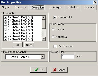
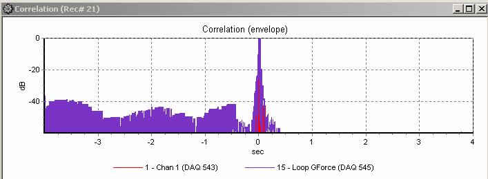
40 Select correlation to display correlation, phase of correlation, envelope of correlation, or spectrum of correlation. Also, correlated Seismic Plots can be displayed. The correlation will be performed using the channel defined in the DAQ units type field = Reference. Other channels can be selected with the assigned reference pull down menu. Seismic Plot can be shown in Vertical or Horizontal display. Also peaks of signals can be clipped. 40 User s Manual

41 5.4.2 Plot Popup Menu The same selections are available in the plot popup menu. On any plot press the right mouse button to bring up the plot menu. Figure Plot Popup Menu Axis allows changing of the x and y axis of the plot. Full view or ctrl +F zooms out completely to show all of plot. Show Legend enables and disables the text legend at the bottom of the plot. DAQLink II System 41

42 5.4.3 Store Plot Menu Store Plot allows the current plot to be saved to memory and viewed later as an overlay to another signal. The first trace in a plot will be stored. The color and name of each stored plot can be changed in the Store Plot Menu. The stored plot data can be saved and later loaded from disk with the Save and Load buttons in the Save Plot menu. The store plot menu is used to compare data using the same sample rate. Data acquired using different sample rates will not be displayed correctly. Figure Store Plot Menu View Stored used to retrieve the saved plots in memory. 42 User s Manual

43 5.4.4 Seismic Plots There is an additional option for a Seismic Plot. When the signal traces plot is selected, the Seismic Plot option can be selected. The plot can be either Horizontal or Vertical. Also, the peak of the signals can be clipped to allow better viewing of multiple channels with large gains. Figure Vertical Seismic Plot The x-axis shows Trace # The Seismic Plots use special keys to control the gain and traces separation. The normal Zoom and axis control used in the other plots do not work well with the Seismic plot The + key on the numeric keypad increases gain of each trace The - key on the numeric keypad decreases gain for each trace The Ins (Insert) key increases separation between traces The Del (Delete) key decreases separation between traces DAQLink II System 43

44 Pressing the right mouse button when it is on the graph, will pull up the plot popup menu. Select the Scale feature. The scale window allows the user to select different scaling options for the Seismic Plot. Absolute Max Applies the same gain to every trace Equalize Applies a different fixed gain to each trace. The gain is different for each trace to equalize the amplitude of the traces. AGC Applies an AGC (automatic gain control) to the data. The AGC algorithm equalizes the energy in the entered time window. Individual Scale The user can enter a fixed scale for each trace. Highlight the channels under the individual scale selection, and use the up down arrows to increase or decrease the scale. Clip Channels- When selected the amplitude of each channel will be clipped, so that it will not overlap to the next channel. Figure Vertical Seismic Plot Scale Feature 44 User s Manual
45 5.4.5 Setting Zoom Level Zoom buttons on the toolbar and the View menu help to adjust a view of a selected plot Axis allows changing of the x and y axis of the plot. Full view or ctrl +F zooms out completely to show all of plot. To adjust zoom with the mouse press the left mouse button and make a box to zoom in on an area of the plot. Start at the top left corner and move to the bottom right corner. Figure Zooming In With The Mouse After releasing mouse button the plot will zoom in. After zooming in, making a box with the mouse from bottom right to top left will zoom out. The plot position can be changed by clicking and holding right mouse button and dragging plot in desired direction. DAQLink II System 45
46 5.4.6 Additional Plot Functions Opens a new plot window Toggles selection of the remove DC feature. When enabled this feature removes the DC component from the input signal before plotting or analyzing data. Status of selection is shown in the Plot info window at the bottom of the screen. 46 User s Manual

47 5.4.7 Filters High Cut, Low Cut and Notch filters can be setup and selected. The Tool bar can be used to select or unselect each filter. If the Toolbar button appears pressed in then the filter is selected. The setup for each filter can be found under the pull down menu Option Preference. The pass band, and stop band frequencies for the Highpass and Lowpass filters can be set. The Notch Filters Center Frequency and the width can also be set. Figure Filter Selection There are two additional options for exporting the data. Normally the remove DC offset when exporting is always enabled The Export filtered data if filter is enabled selection is normally not enabled. When enabled the exported SEG-Y or SEG-2 data will have the filters applied. Normally the raw data is exported and filtering is done by the processing center. DAQLink II System 47

48 5.4.8 Display Settings The Display Settings menu allows the user to select either the A/D units (Volts), or some other display unit which was setup in the DAQLink configuration. For normal Seismic operation A/D units should be used Figure Display Settings 48 User s Manual

49 5.4.9 Auto Operation Auto Operation menu allows the user to setup the following automatic operations Auto Start Acquisition After the data is acquired from all of the selected DAQLink units, the Vscope program automatically sends a new start command out to the selected units. Auto Stack Records- When selected the program will automatically stack the records. See Memory Function Auto Save to Database After the data is acquired from all of the selected DAQLink units, the data is automatically saved to the database with the comment that is in memory. The number of stacked records determines when the stacked record will be saved. Confirm before stacking When selected, the user must confirm that each new record should be added to the stack. Figure Auto Operation DAQLink II System 49


50 Lock and Unlock Menu Option The Lock menu option is normally not used. It is designed to lock the menu when operating in an automatic acquisition mode, and accidental keyboard entries should be ignored. To unlock the keyboard, type ssc as the password. 50 User s Manual


51 Noise Statistic Window The real time Noise Monitor Window can be selected by the Open Noise Statistic button on the tool bar, or by pressing ctrl F7. The Noise Statistic Window shows analysis of the current acquired data. The RMS, maximum, minimum, and DC levels of each trace are shown for the current record. DAQLink II System 51

52 Real Time Noise Monitor The Real Time noise can by shown by checking the Real Time box on the Noise Analysis Window. In this mode the graph will continue to update between records. The Y-axis needs to be selected to a fixed scale. This allows the bar graphs to show the noise levels related to a fixed scale. If auto scale is selected, then the bar graphs show full scale even when the noise level is very small. Default scaling of the x and y axis is autoscale. The scale should be changed to a fixed scale by right clicking the graph and selecting the Axis menu. Select the fixed y-scale so that the bar graphs are small for acceptable noise levels and the bar graphs are large for high noise levels. This allows the operator to monitor the noise level on the spread in real time. On some jobs with large cultural noise, the real time monitor is used to time the trigger event for minimal noise levels. 52 User s Manual


53 5.5 Status information Tabs The Status information tabs at the bottom of the main window provide useful information about the current operation of the system Comment The Comment tab shows the current comment for the record Figure Comment Record Information The Sweep information tab shows important information about the record. Figure Record Information DAQLink II System 53

54 5.5.3 Plot Information The plot information tab shows the status of the plot selections for the current record. Figure Plot Information Status The Status tab shows the status of the DAQLinks connected to the system. This is very useful in troubleshooting wireless Ethernet connections. Figure Status Errors The Error tab shows any communications error or error detected by the DAQLink unit. If an error occurs this tab is automatically displayed. 54 User s Manual


55 5.5.6 Communication Tab The communication tab shows the current status of the DAQLink units that have been selected in the DAQLink setup menu. This is useful when using the wireless Ethernet option. Figure 5.14 Communication Network Tab The Network Tab is used to show the current IP address that was detected when VSCope started. The IP address of the computer should show Figure 5.15 Network Tab DAQLink II System 55

56 5.6 Memory Window Stacking Operation The memory window is used to stack multiple records in real time. Go to the Option Memory selection to open the memory window. The Option Preferences Auto operation settings are also used to set up automatic stacking and storing of multiple records. Each record is stored in memory and can be saved to the database Auto Stack Operation The Auto Operation menu can be used to automate the stacking and saving process. When Auto Stack is enabled the following Hot Keys can be used ESC Stops Acquisition Clear button on Tool Bar will reset Stack number to 1 F2 Ends Stack Saves current Stack and Clears Stack number 56 User s Manual

57 5.6.2 Memory Window Opening the Memory Window shows details of the stacking process Figure Memory Window The memory window tool bar is used to control the operations of the memory window. The memory clear button is used to clear all records from memory. Press this button before starting a new stack The load from database button allows a record from memory to be loaded into the memory buffer The save to database button saves all of the selected records in the memory buffer to the database deleted. viewed. The stack button allows the selected records in memory to be stacked The memory delete button allows the selected record in the memory buffer to be The show record button allows the selected record in the memory buffer to be Figure Memory Window Tool Bar DAQLink II System 57
58 5.7 First Break Pick Feature The Edit -Picker menu or the button on the tool bar is used to enable the first break pick feature. With this feature enabled go to the point on the screen and left click the mouse. Figure Picks on Seismic Plots 58 User s Manual

59 Right click on the screen and select pick table. The pick table will appear on the left side of the seismic plot. The time of each pick is shown in the table. The geophone spacing is entered at the bottom of the screen. The velocity will be computed using the picks and the geophone spacing. DAQLink II System 59

60 The Edit Geometry selection or the on the toolbar is used to select the geometry window. The X (distance) and Z (elevation) of each geophone is entered in the table. Figure Edit Geometry Screen The File Save pick selection is used to save the picks to a File. This pick file is in a standard format to be used by other processing software. 60 User s Manual

61 6.0 Advanced Features 6.1 DAQlink Continuous Recording The DAQlink has the ability to perform almost continuous recording. Typical this type of recording is done using a GPS receiver. This allows the recorded events to be referenced to a GPS time Vscope Auto Start Function The Auto Start function allows the DAQlink to perform continuous recording. There are two basic auto start features with the Vscope and DAQlink system. The Vscope auto start allows the software program to restart the DAQlink unit. The DAQlink auto start allows the DAQlink to auto start itself without being commanded from the Vscope program. Vscope auto start allows the Vscope program to restart the DAQlink unit. This function is enabled by pressing the Auto Start button on the tool bar, or by pressing the (Ctrl + R) Hot Key. This function toggles the auto start on and off. After auto start is enabled, a manual start is required to start the cycle. When the Vscope auto start is enabled, the Vscope program first completes acquisition of the current record, and then automatically restarts the DAQlink unit. There will be a delay between records depending on the acquisition parameters. DAQLink II System 61

62 6.1.2 DAQlink Auto Start Feature The DAQlink also has an auto start feature. This feature is enabled in the Options- Device-DAQ setting menu. Advance Mode must be selected in the Option-Preference menu to enable this screen. There are three selections in this menu 1. Disabled This selection disables the DAQlink auto start 2. Without Start Command When this selection is enabled, the DAQlink will start acquisition as soon as the unit is powered up. This selection is used when the DAQlink will not be connected to a computer running Vscope during acquisition. 3. After Start Command This selection enables the auto start feature after a Start Command has been sent from the Vscope program. This mode is used when the unit is connected to a computer running Vscope. 62 User s Manual
63 6.1.3 GPS Trigger on PPS The DAQlink unit can be set to trigger on the GPS PPS clock. First the trigger on PPS pulse must be selected in the trigger selection, and then the Timer values must also be selected. Timer Value: Start At: The Start At time is used when the exact time of an event is to be used to trigger the DAQlink. Example: 01:00:00 will delay the start of acquisition until 01:00 GMT. (This time is referenced to GPS time). An entry of 00:00:00 is used to allow the repeat every entry to be used without an exact start time. Repeat Every: The repeat every entry is used to determine when the next auto start will occur. Example an entry of 00:10:00 will cause an auto start to occur the next time the GPS time is on an even 10 minute boundary (10:00). Example 1: It is 1:13 GST. The DAQlink is set with the following: Start Time = 00:00:00 Repeat Every = 00:10:00 The DAQlink will start acquisition at the following times: 01:20 GST 01:30 GST 01:40 GST etc.. Example 2: It is 1:13 GST. The DAQlink is set with the following: Start Time = 02:00:00 Repeat Every = 00:10:00 The DAQlink will start acquisition at the following times: 02:00 GST 02:20 GST etc.. DAQLink II System 63
64 6.1.4 Synchronize A/D converters The DAQlink units use a 24 bit Sigma Delta Analog to Digital converter for each channel. These converters can be synchronized to a trigger event. The synchronizing allows the timing to be precise when triggering on an event. If the converters are not synchronized, then the trigger input will use the next available sample from the converter. This will cause up to 1 sample of timing error. When the converters are synchronized the samples will be reset and the data will be synchronized with the trigger event. Synchronizing the converters cause a delay in obtaining a valid result. The following delays are required depending on sample rate: msec 1msec msec 3msec msec 6msec msec 21msec msec 36msec msec 100msec msec -160msec 64 User s Manual

65 6.1.5 Continuous Recording Examples Example 1: Setup DAQlink for Autonomous continuous recording using GPS time. With the following setup the DAQlink will record the data to the internal Flash memory. The data must be downloaded to the Vscope computer after recording is completed. Each record will have seconds. There will be a 0.5 second delay between records to allow for the A-D synchronization. Sample Rate = 1.00 msec Sample Length = seconds Standalone Mode enabled this selection disables the output to the Vscope computer. Trigger on PPS pulse Start Time 00:00:00 Repeat Every 00:10:00 Synchronize A-D Auto Start Without Start command DAQLink II System 65

66 The internal GPS oscillator should also be adjusted to GPS time. This allows for the long records to have correct timing. This selection is found in the Device- Options-Advanced settings tab. 66 User s Manual

67 6.2 Continuous Monitoring of data The Vscope DAQlink system allows continuous monitoring of a small number of channels. Larger number of channels slows the computer program system too much for continuous monitoring. First set up the DAQlink for short records. Example 1 msec sample rate 1 second record Set up the DAQlink to record. Setup system for appropriate trigger method. Either setup for auto trigger for continuous monitoring, or use actual trigger to monitor actual event. Select signal graph and go to axis setup. Select Scope Mode, and set x axis to larger than acquisition time. Start acquisition. Each time the 1 second record is received; the graph is updated in real time. Example shows result of 6 one-second records. DAQLink II System 67

68 6.3 DAQlink Flash Card Download The DAQlink unit stores all data to an internal compact Flash card. The records can be downloaded to the Vscope program after data has been acquired. Before using the Flash Card option, it is best to reset memory in the Flash Card. Reset Memory pressing this button will cause the next record to be recorded at the first of the memory card. Erase Memory This function erases all data from the Flash card. This is not usually required. It may take over an hour to erase all memory from a Large Flash Card. 68 User s Manual
69 6.3.1 Downloading single records To download a single record from the DAQlink Flash card memory, go to Options- Download Menu. After pressing the Get List of Records button, a list of all of the stored data will appear. Select record to be downloaded from the list by highlighting the record. Press Download selected. Record will be downloaded. Press Close to view the record. Press File Save to save the record. DAQLink II System 69


70 6.3.2 Downloading Multiple Records To download a multiple record from the DAQlink Flash card memory, go to File Open Menu, and open the database explorer. From the database explorer, go to the DAQ- Download Records menu. There is also an option to download all of the data stored in the Compact flash. After pressing the Get List of Records button, a list of all of the stored data will appear. Select the records to be downloaded from the list by highlighting the record. Press Download selected. The selected records will be stored to the database. 70 User s Manual
71 6.3.3 Compact Flash Storage The compact flash card stores all recorded data. Different size Compact Flash cards are available. The cards must have a very fast read and write time to be able to record at the fast sample rates. The number of records that can be stored depends on the sample rate, number of channels, and record length. When the memory is full, the DAQlink starts over at the beginning and overwrites the stored data at the beginning of the Flash Card memory. To estimate number of records, the following guidelines can be used. Each sample of data = 3 bytes Header information = about 5% of record length ( normally ignored when estimating) Example: 24 channels at 2msec, 1 second record. 24 channels * 500 samples/sec* 1second* 3 bytes/sample Equals = 36 K bytes Or a 32 Megabyte Compact Flash can hold about 800 records A 1 Gigabyte Compact Flash Card can hold about 27,000 records DAQLink II System 71
72 6.4 Vibrator Quality Control - DAQLink Configuration The Vscope DAQlink system can be setup to analyze Servo Hydraulic Vibrator Equipment. Usually independent accelerometers are mounted on the Reaction Mass and Baseplate assemblies. These signals are compared with the Pilot (True Reference) signal from the recorder. Start Time accuracy; Phase error, Force output, Distortion, and correlation noise are some of the analysis that can be performed Vibrator QC Hardware Setup Connect the accelerometer interface box to the 55-pin connector on the DAQlink II unit. Some accelerometer interface boxes have a 3 pin connector which must be connected to the 3 pin trigger connector on the front of the DAQlink unit. Connect the battery cable to the DAQlink unit Connect the Ethernet cable from the Computer to the DAQlink II unit Connect the True Reference Signal from the Vibrator to Channel 1 on the accelerometer interface box. Connect the Reaction Mass accelerometer to Channel 2 (LRM) on the accelerometer interface box Connect the Baseplate accelerometer to Channel 3 (LBP) on the accelerometer interface box. Channel 4 and Channel 5 are optional inputs for additional accelerometers. When connected to the independent accelerometers the Switch should be turned on. The switch enables the internal current regulator and powers the independent accelerometers. One switch controls the current regulators on Channels 2 and 3, and the other switch controls the current regulators on Channels 4 and 5. When connected to any other accelerometer or signal, the current regulators should be turned off. The accelerometers directly from the Pelton or Sercel Vibrator controller can be input into the DAQlink unit. In this case the current regulators should be off, because the Sercel or the Pelton controller will power the accelerometers. The TB (Time Break) on the interface box can be connected to the Time Break signal on the control electronics. Make sure the independent accelerometers are attached securely to the vibrator assembly. The magnets will work OK if the there is a clean flat surface to mount the accelerometers. To insure good results, it is best to mount the accelerometers directly to the vibrator assembly. 72 User s Manual


73 6.4.2 Vibrator QC Software Setup Start a new project for Vibrator QC. Go to File New project and select Project Mode as VibratorQC.. Go to the Options Preferences Menu Display Options and select Display Units to allow lbs to be displayed on the graphs. Use A/D units to display voltage levels. DAQLink II System 73

74 Setup the Weights for the Vibrator to be tested. Go to the Option Vibrator Menu This opens up the Vibrator Setup Menu The proper weights of the Reaction Mass and Baseplate must be entered for each vibrator to be tested. Also the sensitivity of the accelerometers to be used must also be entered. The Vibrator QC option includes independent accelerometers. These accelerometers have a sensitivity of 10 mv/g. The control accelerometers from Seismic Source Co. have a sensitivity of 25 Mv/G. The Sercel scaling is used when connected directly to the accelerometer signals on the Sercel VE432 vibrator control electronics. After entering the correct weights press close button. 74 User s Manual
75 Go to the Options- Device DAQ Settings menu. Standard Menu Display First Select the QC mode of the operation. Vibrator QC This mode is used when testing a single Vibrator using the Force Two test cable or the VibQC accelerometer I/F box Wireline Is used when testing multiple vibrators using the SSC Wireline adapter box Zero Time is used when comparing the True Reference from the Encoder to the True Reference in the Vibrator units. After selecting the QC mode, then select the signals to be recorded. Typically in Vibrator QC Mode only the first three channels are used. Ch1 Reference Ch2 Baseplate Ch3 Reaction Mass Select Sample interval and Acquisition Time to match the sweep. Display units should match the weights used in the Vibrator Parameters. If the Vibrator s weights were entered in pounds then select lbs. If the vibrator weights were entered in Kg, then select Kg. Select Trigger Source Auto, Time Break on Reference Amplitude DAQLink II System 75

76 Advance Menu Display Figure Vibrator QC DAQ settings The advance menus allow more flexibility in the setup, and additional information must be entered for proper operation. Signal type is very important when doing vibrator quality control. Channel 1 type should be selected to REF. This selects channels number one as the reference channel this signal will be used for the reference signal in the Vibrator analysis. Only one signal can be selected as the reference signal. Channel 2 type is selected to be LRM Loop Reaction Mass. This is the signal connected to the Reaction Mass accelerometer. Only one signal per DAQlink unit should be selected for LRM. If a second accelerometer is to be placed on the reaction mass, then select the second signal s type to be SRM Similarity Reaction Mass. Channel 3 type is selected to be LBP - Loop Baseplate. This is the signal connected to the Baseplate accelerometer. Only one signal per DAQlink unit should be selected for LBP. If a second accelerometer is to be placed on the baseplate, then select the second signal s type to be SBP Similarity Baseplate. Select Auto for DC removal This will remove most of the DC bias from the accelerometer signal. The remaining DC must be removed by the Vscope software. Be sure to have DC removal selected in the Vscope parameters. This setting can be verified by looking at the Plot Info Tab at the bottom of the screen. The units can be set to either pounds (lbs) or Kilograms. This entry is used on the graphs for display. Any texts can be entered here. Normally it is either lbs of Kg. 76 User s Manual

77 Select Vibrator from the list. Figure Vibrator QC Weight settings The weights must be entered correctly for the Vibrator Analysis to be correct Reaction Mass Weight enter the weight of the Reaction Mass in either pounds or Kilograms. Baseplate Weight enter the weight of the Baseplate in either pounds or Kilograms Hold Down Weight enter the hold down weight of the vibrator. This entry is only used to scale the reference signal when the y- axis is selected for weight. Enter the accelerometer sensitivity (milivolts per G) of each accelerometer used. The independent accelerometers supplied by Seismic Source Co. are typically 10 mv/g. The Pelton M4 and M5 accelerometers are 25 mv/g. The Seismic Source M6 accelerometers are 25 mv/g The Sercel scaling is used when connected directly to the accelerometer signals on the Sercel VE432 vibrator control electronics. DAQLink II System 77

78 Figure Vibrator QC Trigger settings The trigger is normally done using either the Vibrator s Reference signal or the Time Break signal from the Vibrator controller. When using the Reference for trigger. Select channel one as shown above and select a level that allows the system to trigger reliably. A pretrigger time is also provided. This allows viewing of the signals before the triggered event. The Time Break signal can also be used to trigger the DAQlink unit. The time break from the Vibrator control system provides a signal at the start of the sweep. This allows consistent triggering when changing sweep parameters. The Time Break from the Pelton Advance II series vibrator electronics does not work well when starting locally. It should work when the Encoder starts the Vibrator Electronics. It is often a good idea to use the auto trigger function first when getting setup to do the test. This allows the operator to look at the signal levels and determine if everything is setup correctly. 78 User s Manual
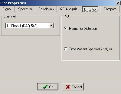
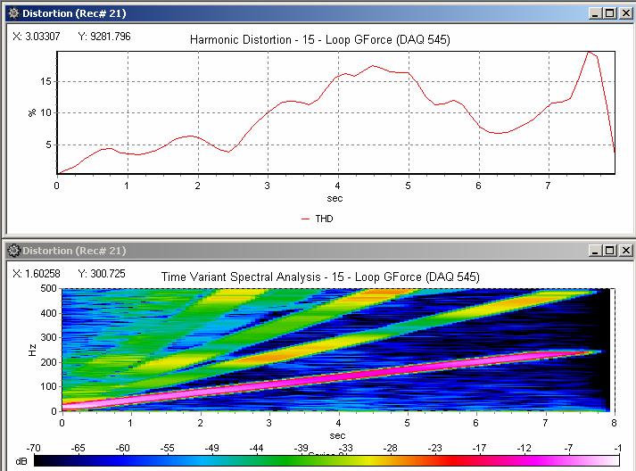
79 6.4.3 Vibrator QC plots Vibrator QC plots includes the following: requires Options Preferences Display Settings to be set to VibQC Select Vib Analysis to do one of the following Phase Fundamental Output Peak Output Frequency versus Time of Sweep The Vib Analysis routines use the channel defined in the DAQ unit type field =Reference. Other channels can be selected with the assigned reference pull down menu. Select to display distortion analysis of signals Harmonic Distortion uses the channel defined in the DAQ unit type field =Reference. The energy of the signal selected is computed for the 1 st, 2 nd, 3 rd, 4 th and 5 th harmonics of the Reference Signal. Time Variant Spectral Analysis Performs spectral analysis on small time windows of the selected signal. The resulting plots shows time in the x-axis, frequency in the y-axis, and amplitude in the z-axis. The z-axis can be changed by the user. Press the right mouse button on the display to access the axis menu. If the default z-axis is max =0 and min=-170, then the graph is displaying distortion that is 170 db below the maximum. After changing the minimum to 60, the graph will then show the distortion that is between 0 and 60 db. This is very useful in examining distortion levels. Select to compare two signals. Used to compare accelerometer amplitude and phase. Toggles inversion of accelerometer signals status of inversion can be shown in the Plot info window at the bottom of the screen. Toggles selection of the smooth plot feature. Status of this bit can be shown in the Plot info window at the bottom of the screen. DAQLink II System 79


80 Vscope Graph Options Signal Graphs 80 User s Manual


81 Spectrum Plot DAQLink II System 81
82 Correlation 82 User s Manual


83 Vibrator QC Analysis DAQLink II System 83
84 Distortion Analysis 84 User s Manual

85 Compare Plots DAQLink II System 85

86 Overlay Plot menu 86 User s Manual
 from either the Encoder or Vibrator Electronics Connect Channel 2 to one of the Magnetic Accelerometer using the")
87 6.4.4 Vibrator QC example Setup Bird Dog II Connect BirdDogII to power (9-18 volts DC) Connect Bird Dog Ethernet Cable to Computer Connect Vibrator QC interface to the 55-pin connector on the Bird Dog II unit Vibrator QC interface Connect Channel 1 to True Reference Signal (Pilot) from either the Encoder or Vibrator Electronics Connect Channel 2 to one of the Magnetic Accelerometer using the coax cable provided with the accelerometer. Connect Channel 3 to the Magnetic Accelerometer using the coax cable provided with the accelerometer. Turn the Current Regulator to the on position Place Channel 2 accelerometer on the Baseplate of the Vibrator Place Channel 3 accelerometer on the Reaction Mass of the Vibrator Setup Vscope as follows: Go to the Options Vibrator Menu and setup the Vibrator s parameters. Make sure Weights match the Vibrator s weight Use Sensitivity = 10 mv/g when using the magnetic accelerometers DAQLink II System 87

88 Options Device DAQsettings Menu Select Acquisition time to match Sweep length 88 User s Manual

89 Select Vibrator Type to match Weights of the vibrator to be tested M18 shown Select OK when finished. DAQLink II System 89

90 Acquire Data Start Vscope by Clicking the Start button or pressing A on the keyboard Start a sweep in the Vibrator. The Vscope should trigger when the vibrator starts shaking. If not check the True reference signal. Display Results Select New Plot and select signal plot as shown 90 User s Manual

91 The display should look similar to Channel 1 is reference sweep Channel 2 is Baseplate signal Channel 3 is Reaction Mass Signal Channel 4 is the computed Weighted Sum signal or Ground Force This plot provides a quick check that all of the signals are working correctly. DAQLink II System 91

92 Open New Plots and select the QC analysis that is required. Normal QC plots include: Vibrator Analysis Phase Loop Ground Force compared to Reference Vibrator Analysis Fundamental Force Loop Ground Force Vibrator Analysis Peak Force Loop Ground Force After selecting these plots, Press Tile H the screen should appear as shown. Note: Press Invert to change phase of Ground Force from 180 degrees to 0 degrees Right Click on any graph to change scale or axis Press File Save to save data 92 User s Manual
Tach Facts V3.0 Software
 Tach Facts V3.0 Software Download runs from your Auto Meter Playback Tach with Tach-Facts Software. Instr. No. 2650-978 Tach Facts provides complete race analysis on your personal computer. Introduction
MCA8000D OPTION PA INFORMATION AND INSTRUCTIONS FOR USE I. Option PA Information
 MCA8000D Option PA Instructions and Information Rev A0 MCA8000D OPTION PA INFORMATION AND INSTRUCTIONS FOR USE I. Option PA Information Amptek s MCA8000D is a state-of-the-art, compact, high performance,
Manual. User Reference Guide. Analysis Application (EMG) Electromyography Analysis
 Electromyography Analysis") Phone: (888) 765-9735 WWW.MINDWARETECH.COM User Reference Guide Manual Analysis Application Electromyography Analysis (EMG) Copyright 2014 by MindWare Technologies LTD. All Rights Reserved. 1 Phone: (614)
Phone: (888) 765-9735 WWW.MINDWARETECH.COM User Reference Guide Manual Analysis Application Electromyography Analysis (EMG) Copyright 2014 by MindWare Technologies LTD. All Rights Reserved. 1 Phone: (614)
OPERATING MANUAL AND TECHNICAL REFERENCE
 MODEL WFG-D-130 HIGH SPEED DIGITAL 3 AXIS FLUXGATE MAGNETOMETER OPERATING MANUAL AND TECHNICAL REFERENCE December, 2012 Table of Contents I. Description of the System 1 II. System Specifications.. 2 III.
Please Check the Installation Notes Portion of this Manual Before Installing the Software Update
 SOFTWARE MANUAL V.1.1.7 This manual is designed for viewing on a computer with ADOBE reader and has hyperlinks throughout to help navigation between topics. To view this manual on a computer, select the
Student Quick Reference Guide
 Student Quick Reference Guide How to use this guide The Chart Student Quick Reference Guide is a resource for PowerLab systems in the classroom laboratory. The topics in this guide are arranged to help
AKELA Vector Network Analyzer (VNA) Quick Start Guide
 Quick Start Guide") AKELA Vector Network Analyzer (VNA) Quick Start Guide Copyright AKELA, Inc. 2012, all rights reserved http:\\akelainc.com LabVIEW and LabWindows are registered trademarks of National Instruments Incorporated
AKELA Vector Network Analyzer (VNA) Quick Start Guide Copyright AKELA, Inc. 2012, all rights reserved http:\\akelainc.com LabVIEW and LabWindows are registered trademarks of National Instruments Incorporated
N2KExtractor. Maretron Data Extraction Software User s Manual
 N2KExtractor Maretron Data Extraction Software User s Manual Revision 3.1.6 Copyright 2017 Maretron, LLP All Rights Reserved Maretron, LLP 9014 N. 23rd Ave #10 Phoenix, AZ 85021-7850 http://www.maretron.com
MindWare Electromyography (EMG) Analysis User Reference Guide Version Copyright 2011 by MindWare Technologies LTD. All Rights Reserved.
 Analysis User Reference Guide Version Copyright 2011 by MindWare Technologies LTD. All Rights Reserved.") MindWare Electromyography (EMG) Analysis User Reference Guide Version 3.0.12 Copyright 2011 by MindWare Technologies LTD. All Rights Reserved. MindWare EMG 3.0.12 User Guide Internet Support E-mail: sales@mindwaretech.com
MindWare Electromyography (EMG) Analysis User Reference Guide Version 3.0.12 Copyright 2011 by MindWare Technologies LTD. All Rights Reserved. MindWare EMG 3.0.12 User Guide Internet Support E-mail: sales@mindwaretech.com
ZLog Z6R Altitude Data Recording and Monitoring System
 ZLog Z6R Altitude Data Recording and Monitoring System 2014-04-28 Page 1 of 24 Introduction ZLog was designed to provide a lightweight, compact device for measuring and recording altitude over time. It
Canlan INSTALLATION MANUAL
 Canlan INSTALLATION MANUAL August 2014 Table of Contents Introduction... 4 Overview... 5 RJ45 Connector and Status LEDs... 5 Power Input... 6 RS232 / RS485 Connectors... 7 Installing the Canlan Software...
TABLE OF CONTENTS COPYRIGHT INTRODUCTION...3 PRODUCT OVERVIEW...3 COMPONENTS AND FEATURES...3 HARDWARE INSTALLATION
 TABLE OF CONTENTS COPYRIGHT...2 1. INTRODUCTION...3 PRODUCT OVERVIEW...3 COMPONENTS AND FEATURES...3 HARDWARE INSTALLATION...3 2. MFP SERVER INSTALLATION...5 PREPARATION...5 CONFIGURATION SOLUTION TABLE...5
MotionView Configuration and Programming Software USER S MANUAL
 MotionView Configuration and Programming Software USER S MANUAL IM94MV01C Table of Contents 1 MotionView Software Overview......................................... 3 1.1 Installation and Package Revision.................................................
Longshine Technologie Europe GmbH LCS-MFP101-2 Multifunction Printserver
 Longshine Technologie Europe GmbH LCS-MFP101-2 Multifunction Printserver www.longshine.de TABLE OF CONTENTS COPYRIGHT...2 1. INTRODUCTION...3 PRODUCT OVERVIEW...3 COMPONENTS AND FEATURES...3 HARDWARE INSTALLATION...3
Longshine Technologie Europe GmbH
 Longshine Technologie Europe GmbH www.longshine.de TABLE OF CONTENTS COPYRIGHT...2 1. INTRODUCTION...3 PRODUCT OVERVIEW...3 COMPONENTS AND FEATURES...3 HARDWARE INSTALLATION...3 2. MFP SERVER INSTALLATION...5
ATL20 ATL30 Automatic transfer switch controller
 I 194 GB 07 07 ATL20 ATL30 Automatic transfer switch controller REMOTE CONTROL SOFTWARE MANUAL Summary Introduction... 2 Minimum resources of the PC... 2 Installation... 2 Activation of the PC-ATL connection...
User s Manual SeisOpt Picker Version 1.5
 User s Manual SeisOpt Picker Version 1.5 For support contact support@optimsoftware.com Optim LLC UNR MS 174 1664 N. Virginia St. Reno, NV 89557-0141 USA Phone: 775.784.6613 * Fax: 775.784.1833 CONTENTS
GXLink MultiChannel Wave Inserter Model SP-631
 800173-0A Digital High Speed GXLink MultiChannel Wave Inserter Model SP-631 User Manual Copyright 2009 It is prohibited to copy, reproduce or distribute this information in whole or in part without the
Lab IP Addresses and Network Communication
 Lab 3.5.2 IP Addresses and Network Communication Objectives Build a simple peer-to-peer network and verify physical connectivity. Assign various IP addresses to hosts and observe the effects on network
Vibration Analyzer Version 1.0.2
 Vibration Research Corporation 6437 28 th Ave. Hudsonville, MI 49426 support@vibrationresearch.com Phone: (616) 669-3028 Fax: (616) 669-5337 Vibration Analyzer Version 1.0.2 File menu The File menu is
OPERATION MANUAL. MV-410HS Layout Editor. Version higher. Command
 OPERATION MANUAL MV-410HS Layout Editor Version 3.0 - higher Command Command Table of Contents 1. Setup... 1 1-1. Overview... 1 1-2. System Requirements... 1 1-3. Operation Flow... 1 1-4. Installing MV-410HS
Refractor 8.1 User Guide
 Refractor 8.1 User Guide Copyright 2016, All rights reserved. Table of Contents Preface...1 Conventions Used in This Guide...1 Where to Find Information...1 Technical Support...2 Feedback...2 Chapter 1
DCP585CW Windows Network Connection Repair Instructions
 Difficulty printing from your PC can occur for various reasons. The most common reason a networked Brother machine may stop printing, is because the connection between the computer and the Brother machine
Geogiga Seismic Pro 9.0 Release Notes
 Geogiga Seismic Pro 9.0 Release Notes Copyright 2018, All rights reserved. Table of Contents Introduction...1 Part 1 New Modules...3 Modeling2D...3 Surface RT...4 Part 2 General Enhancements...5 Part 3
Docking Station DS-U4WEB with web server version 1 Instruction Manual
 Page 1 of 15 Docking Station DS-U4WEB with web server version 1 Page 2 of 15 Table of contents 1 Overview... 3 2 Description... 3 2.1 Connector identification... 3 2.2 Probe inputs... 4 2.3 Logical inputs
Dash HF Family High Speed Data Acquisition Recorder
 Dash HF Family High Speed Data Acquisition Recorder QUICK START GUIDE (1) Introduction (2) Getting Started (3) Hardware Overview (4) Menus & Icons (5) Using the Dash HF (6) Setting Up the Display Appearance
Quick Start Guide Agilent Technologies 14565A Device Characterization Software for Windows 98, Windows NT 4.0, Windows 2000 and Windows XP
 Quick Start Guide Agilent Technologies 14565A Device Characterization Software for Windows 98, Windows NT 4.0, Windows 2000 and Windows XP sa Contents Description...3 System Requirements...3 Installing
Servo TestView Windows Edition Instruction Manual
 Servo TestView Windows Edition Instruction Manual Interactive Instruments, Inc. Corporations Park Bldg. 704 Scotia, N.Y. 12302 www.interactiveinstruments.com Information in this document is subject to
micromax R Getting Started Guide
 PN# 34-2114 Rev 1 04-25-2007 micromax R Introduction Introduction Thank you for purchasing Agile System s micromax R product. This guide covers how to install DPWin, connect, configure and tune a motor
Simulation and Emulation of the Display and Control Unit of Advance Optima
 Advance Operation Optima Remote HMI Simulation and Emulation of the Display and Control Unit of Technical Information 30/24-311-1 EN Table of Contents Page Chapter 1 Chapter 2 Chapter 3 Survey Description
SW860 FlukeView Software
 SW860 FlukeView Software Version 2 (Windows and DOS) Users Manual PN 944520 January 1995 Rev. 1 12/95 1995 Fluke Corporation, Inc. All rights reserved. Printed in U.S.A. All product names are trademarks
Hands-on Lab 2: LabVIEW NI-DAQ Basics 2
 Hands-on Lab 2: LabVIEW NI-DAQ Basics 2 Recall that the final objective is position regulation using computer-controlled state feedback. Computer control requires both software, like LabVIEW and hardware,
RC-SV Configuration Guide Revision 3
 Kramer Electronics, Ltd. RC-SV Configuration Guide Revision 3 Software Version 2.1.2.32 Intended for Kramer Technical Personnel or external System Integrators. To check that you have the latest version,
Instruction Manual. ROYTRONIC EXCEL Series AD9 Programming Guide Electronic Metering Pumps
 Instruction Manual ROYTRONIC EXCEL Series AD9 Programming Guide Electronic Metering Pumps For file reference, please record the following data: Model No: Serial No: Installation Date: Installation Location:
DW Tomo 8.1 User Guide
 DW Tomo 8.1 User Guide Copyright 2016, All rights reserved. Table of Contents Preface...1 Conventions Used in This Guide...1 Where to Find Information...1 Technical Support...2 Feedback...2 Chapter 1 Introducing
Cal-Bay Systems XY Plotter, Time-Base Recorder, Automated Tester. Users Guide. Rev 3.1
 Cal-Bay Systems XY Plotter, Time-Base Recorder, Automated Tester Users Guide Rev 3.1 Contents... 1 Quick Start Guide... 2 Selecting a Test Specification... 3 Clearing Traces... 4 Saving Traces...4 Loading
Introduction to Solo Forest
 Introduction to Solo Forest Project Settings Collecting Data Office Procedures - Exporting Shapefiles - Syncing with the PC - Transferring files Opening Solo Forest To open Solo Forest, select Start >
SAFARI General Instructions
 SAFARI General Instructions Open Excel. Click on the Data Tab. Click on From Other Sources. Select From Miscrosoft Query. Select the Database you would like to pull from: Insert your Reflections Password
6220 Ethernet-Based Voltage Measurement Module
 Ethernet-Based Voltage Measurement Module Features 12 voltage inputs 16-bit, 100 khz per channel sample rate ±10 V input range Eight digital I/O Simultaneous sampling BNC connectors Multiple trigger modes
DAQFactory U3 Tutorial Getting Started with DAQFactory-Express and your LabJack U3 11/3/06
 DAQFactory U3 Tutorial Getting Started with DAQFactory-Express and your LabJack U3 11/3/06 Congratulations on the purchase of your new LabJack U3. Included on your installation CD is a fully licensed copy
DaqPRO Solution. User Guide INNOVATIVE MONITORING SOLUTIONS ALL IN ONE SOLUTION FOR DATA LOGGING AND ANALYSIS.
 INNOVATIVE MONITORING SOLUTIONS www.fourtec.com User Guide including DaqLab FACTORIES Monitoring product quality throughout the entire manufacturing cycle TESTING STANDARDS Ensuring quality control and
Thermal Transient Test Installation and Operating Manual
 Thermal Transient Test Installation and Operating Manual 2705A De La Vina Street Santa Barbara, California 93105 Telephone (805) 682-0900 descon@silcom.com www. santabarbaraautomation.com Installation
PTZOptics IP Joystick Controller
 PTZOptics IP Joystick Controller Third Generation IP Joystick Controller Installation & Operation Manual Please visit www.ptzoptics.com for the most up to date version of this manual Page1 Table of Contents.
Temposonics. User s Manual. MH-CAN Testkit. CANopen & SAE J1939. Absolute, Non-Contact Position Sensors. Document Part Number.
 Temposonics Absolute, Non-Contact Position Sensors MH-CAN Testkit Document Part Number 551292 Revision A CANopen & SAE J1939 Kit includes the CAN Test Interface software with a user friendly Graphical
User Manual. MPPTracker. Management Software for Solar Charge Controller. Version: 1.2
 User Manual MPPTracker Management Software for Solar Charge Controller Version: 1.2 Table of Contents 1. MPPTracker Overview... 1 1.1. Introduction... 1 1.2. Features... 1 2. MPPTracker Install and Uninstall...
AbraScan Test Strip Reader Digital Reading of Test Strips for the Determination of Cyanotoxins in Contaminated Water Samples
 AbraScan Test Strip Reader Digital Reading of Test Strips for the Determination of Cyanotoxins in Contaminated Water Samples Product No. 475025 1. General Description The AbraScan RDS-1500 Test Strip Reader
Lantech LSC-1102B SERIAL TO TCPIP CONVERTER. User Manual
 Lantech LSC-1102B SERIAL TO TCPIP CONVERTER User Manual V1.0 Sep 2016 Table of Contents 1. Introduction 3 Overview 4 Product Specifications 8 2. Description & Installation 10 Product Panel Views 10 LED
For the SIA Features of GigaView. Introduction. Initial Dialog Bar
 For the SIA-3000 Features of GigaView One button solution for multiple DataCom compliant standards jitter testing. Comprehensive and versatile jitter analysis software enables users to quickly understand
CYCLONE TIMING MODULE - 2 User Guide
 CYCLONE TIMING MODULE - 2 User Guide Version 4. January 2 Last Mile Gear Sales:.36.44.599 ext. Support:.36.44.599 ext. 2 Fax:.36.44-599 support@lastmilegear.com www.lastmilegear.com GETTING STARTED Plug
RC-SV Configuration Guide (Rev 4)
") Kramer Electronics, Ltd. RC-SV Configuration Guide (Rev 4) Software Version 2.1.2.69 Intended for Kramer Technical Personnel or external System Integrators. To check that you have the latest version, go
Kramer Electronics, Ltd. RC-SV Configuration Guide (Rev 4) Software Version 2.1.2.69 Intended for Kramer Technical Personnel or external System Integrators. To check that you have the latest version, go
PTZOptics IP Joystick Controller
 Page1 PTZOptics IP Joystick Controller Second Generation IP Joystick Controller Installation & Operation Manual Please visit www.ptzoptics.com for the most up to date version of this manual Page2 Table
User's Guide. For CarChip and CarChip E/X 8210 & 8220
 User's Guide TM For CarChip and CarChip E/X 8210 & 8220 Product Number: 8210, 8220 Davis Instruments Part Number: 7395.064 DriveRight CarChip User s Manual Rev A (January 2, 2003) Davis Instruments Corp.,
Blaze for SoundTrack LxT. Industrial Hygiene Software Technical Reference Manual
 Blaze for SoundTrack LxT Industrial Hygiene Software Technical Reference Manual Larson Davis Blaze Software for use with the SoundTrack LxT Technical Reference Manual IBLZ.02 Rev E Copyright Copyright
Networking the printer
 Networking the printer General networking Networking overview A network is a collection of devices such as computers, printers, Ethernet hubs, wireless access points, and routers connected together for
RIVA / Athena Pro-Series ECU
 RIVA / Athena Pro-Series ECU USING SOFTWARE (MAYA) Running Maya for First Time Once installed, Maya is available in the Start menu under Programs -> Maya, or from a desktop short cut, if created. The first
First-Time drive.web Network Administration
 First-Time drive.web Network Administration Scope This document is intended for drive.web users who are creating a standalone network for the first-time. More complex systems requiring Wide Area Network
MFC790CW Windows Network Connection Repair Instructions
 Difficulty printing from your PC can occur for various reasons. The most common reason a networked Brother machine may stop printing, is because the connection between the computer and the Brother machine
EE 210 Lab Assignment #2: Intro to PSPICE
 EE 210 Lab Assignment #2: Intro to PSPICE ITEMS REQUIRED None Non-formal Report due at the ASSIGNMENT beginning of the next lab no conclusion required Answers and results from all of the numbered, bolded
JANOME ELECTRO PRESS. Operation Manual. <PC Operation>
 JANOME ELECTRO PRESS JP-104 JP-204 JP-504 JP-1004 JP-1504 JP-3004 JP-5004 JPH-104 JPH-204 JPH-504 JPH-1004 JPH-1504 JPH-3004 JPH-5004 JPU-104 JPU-204 JPU-504 JPU-1004 JPU-1504 JPU-3004 JPU-5004 JPU-8004
Quick Start Guide. January EAZ0081L02A Rev. A
 Quick Start Guide January 2014 EAZ0081L02A Rev. A Trademarks Snap-on and Vantage Ultra are trademarks of Snap-on Incorporated. All other marks are trademarks or registered trademarks of their respective
AEMLog Users Guide. Version 1.01
 AEMLog Users Guide Version 1.01 INTRODUCTION...2 DOCUMENTATION...2 INSTALLING AEMLOG...4 AEMLOG QUICK REFERENCE...5 THE MAIN GRAPH SCREEN...5 MENU COMMANDS...6 File Menu...6 Graph Menu...7 Analysis Menu...8
Revision Notes: July2004 Generate tutorial for single transistor analysis. Based on existing schematic entry tutorial developed for ECE410
 Cadence Analog Tutorial 1: Schematic Entry and Transistor Characterization Created for the MSU VLSI program by Professor A. Mason and the AMSaC lab group. Revision Notes: July2004 Generate tutorial for
R4 Engine Programming Software
 R4 Engine Programming Software Description: The R4 software is a Windows TM based software package that provides the user interface for a variety of Split Second engine management products. It controls
Complete Tutorial (Includes Schematic & Layout)
") Complete Tutorial (Includes Schematic & Layout) Download 1. Go to the "Download Free PCB123 Software" button or click here. 2. Enter your e-mail address and for your primary interest in the product. (Your
Complete Tutorial (Includes Schematic & Layout) Download 1. Go to the "Download Free PCB123 Software" button or click here. 2. Enter your e-mail address and for your primary interest in the product. (Your
USB Instruments EasyLogger for PS40M10 "Swordfish" Help
 USB Instruments EasyLogger for PS40M10 "Swordfish" Help I EasyLogger for PS40M10 Help Table of Contents Part I Introduction 3 1 Welcome to... EasyLogger for PS40M10 3 2 EasyLogger... Features 4 Part II
WLAN MIERUZZO BASIC SOFTWARE
 DK-5000 Series WLAN MIERUZZO BASIC SOFTWARE USER S MANUAL DK-5005A, DK-5010A, DK-5030A DK-5005B, DK-5010B, DK-5030B DK-5005C, DK-5010C, DK-5030C DK-5005D, DK-5010D, DK-5030D This manual was last revised
Digital Proximity System Software Installation Manual
 Digital Proximity System Software Installation Manual Doc# 100961 REV A (February 2018) Table of Contents Purpose...2 How to Download DPS 1.35 Software from the Internet...3 The difference between Simulate
Phantom Quick Start User Guide Vision Research - AMETEK Material Analysis Division
 Phantom Quick Start User Guide Software Revision: 2.7.756.2 Updated: Wednesday, January 27, 2016 Contents 3 Table of Contents Foreword 0 Part I Quick Start Guides 6 1 Phantom v-series Cameras via Phantom
MESURgauge Software. User s Guide
 MESURgauge Software User s Guide Thank you Thank you for purchasing MESURgauge software, a data collection and analysis program developed to: Measure Collect data from digital force gauges, torque gauges,
Bose ControlSpace Designer Software. User Guide
 Bose ControlSpace Designer Software User Guide 2005 Bose Corporation. No part of this work may be reproduced, modified, distributed or otherwise used without prior written permission. Contents Introduction
EECS 211 CAD Tutorial. 1. Introduction
 EECS 211 CAD Tutorial 1. Introduction This tutorial has been devised to run through all the steps involved in the design and simulation of an audio tone control amplifier using the Mentor Graphics CAD
Table of Contents. Part I USB Communication. Part II User Interface. Part III User Settings (Tab Control) DFS-1000 Dataview. 2 File Menu.
 DFS-1000 Dataview. 2 File Menu.") 2 Table of Contents Part I USB Communication 3 1 Important... Information 3 2 Connecting... Controller 3 Part II User Interface 4 1 Overview... 4 2 File Menu... 5 3 Options... Menu 6 4 Help Menu... 6 5
2 Table of Contents Part I USB Communication 3 1 Important... Information 3 2 Connecting... Controller 3 Part II User Interface 4 1 Overview... 4 2 File Menu... 5 3 Options... Menu 6 4 Help Menu... 6 5
Capstone Appendix. A guide to your lab computer software
 Capstone Appendix A guide to your lab computer software Important Notes Many of the Images will look slightly different from what you will see in lab. This is because each lab setup is different and so
SN388 New Features. Summer SN388 Software Release 8.4. SQC-Pro Release 1.2. VE432 Release 3.0. CoPilot
 SN388 New Features Summer 1999 SN388 Software Release 8.4 SQC-Pro Release 1.2 VE432 Release 3.0 CoPilot SN388 Software Release 8.4 Remote access of the SN388 : CoPilot. Installation procedure of the Solaris
VR9500. Advantages Ease of Use. Features
 Ease of Use system and confi gured a test within minutes of unpacking the box. Additionally, our customer support PC & Windows Integration The integrates seamlessly with your PC and Windows operating system,
Plus-Minus Method of Refraction Seismic Data Analysis in RadExPro Software
 Plus-Minus Method of Refraction Seismic Data Analysis in RadExPro Software (Revision of 28.11.2016) DECO Geophysical SC Moscow State University Science Park 1-77 Leninskie Gory Moscow 119992, Russia Tel.:
FSA-CU Configuration Utility Programming Guide
 FSA-CU Configuration Utility Programming Guide Revision 3 October 2013 Introduction The following guide will show you the basics of the FSA-CU configuration utility program. The CU can be used with the
N2KExtractor. NMEA 2000 Data Extractor Software. User s Manual
 N2KExtractor NMEA 2000 Data Extractor Software User s Manual Revision 1.0.0 Copyright 2012 Maretron, LLP All Rights Reserved Maretron, LLP 9014 N. 23 rd Ave #10 Phoenix, AZ 85021-7850 http://www.maretron.com
ProjectorNetTM Adapter Quick Start Guide
 ProjectorNetTM Adapter Quick Start Guide Adapter networking 1. Quick Start The ProjectorNet Adapter kit contains the following items: ProjectorNet Serial to Ethernet Adapter Cable Adapter, ProjectorNet
DATA ACQUISITION USING THE BIOPAC DATA SYSTEM
 DATA ACQUISITION USING THE BIOPAC DATA SYSTEM Acquiring Your Data: NOTE: Section A1 to A3 will be done for you before enter the lab. Therefore, the system should be set up and ready to acquire data. It
R&S RTB2000 Oscilloscope Release Notes Firmware Version
 Oscilloscope Release Notes Firmware Version 02.202 These Release Notes describe the following models and options: R&S RTB2004 Oscilloscope, order no. 1333.1005K04 R&S RTB2002 Oscilloscope, order no. 1333.1005K02
GV-AS200 Controller. Hardware Installation Guide
 GV-AS200 Controller Hardware Installation Guide Before attempting to connect or operate this product, please read these instructions carefully and save this manual for future use. 2008 GeoVision, Inc.
PROJECTOR MODEL SETUP MANUAL
 PROJECTOR MODEL XV-Z30000 SETUP MANUAL Connecting Pin Assignments... 2 RS-232C Specifications and Commands... 4 Setting up the Projector Network Environment... 8. Connecting the Projector to a Computer...
MARINER RS. SOFTWARE for ControlLogix HM1756 SGI-TSM. Rev /10/2007
 MARINER RS SOFTWARE for ControlLogix HM1756 SGI-TSM Rev 1.00 1/10/2007 HELM INSTRUMENT COMPANY, INC. 361 WEST DUSSEL DRIVE MAUMEE, OHIO 43537 419-893-4356 419-893-1371 (FAX) TABLE OF CONTENTS Introduction...2
User s Guide. Ethernet Module for Barcode Printer
 User s Guide Ethernet Module for Barcode Printer 1. ETHERNET MODULE... 2 1-1. Functions... 2 1-2. General Specifications... 2 2. ETHERNET MODULE INSTALLATION... 3 2-1. Ethernet Module Installation for
The iworx 214 and LabScribe V2.0 Tutorial. Overview
 The iworx 214 and LabScribe V2.0 Overview Figure T-1-1: The front and rear panels of IWX/214. The data acquisition unit used in the iworx teaching kits is the IWX/214 (Figure T-1-1 on page T-1-1). The
This manual has been created to help end-users step through the various pages and functions of EAWPilot and access all of its powerful features.
 EAWPilot Introduction To EAWPilot EAWPilot is an extremely fast and intuitive software created to aid the users of the UX8800, UX3600 + NT products in evaluating, building, storing and recalling complex
ADR. - Configuration and Functionality USER MANUAL
 ADR - Configuration and Functionality USER MANUAL Installation Contents Installation... 3 Dimensions... 3 Configuration... 4 Connection to the ADR... 4 Password Support... 5 Device Configuration... 5 Device
ULTRALOW POWER 24-BIT DUAL SEISMIC DATA RECORDER WITH INTERNAL SCU CONTROLLER Model DR4050-A-SCU/IF
 ULTRALOW POWER 24-BIT DUAL SEISMIC DATA RECORDER WITH INTERNAL SCU CONTROLLER Model DR4050-A-SCU/IF The eentec DR4050-A-SCU/IF is a rugged, ultra low power, high-performance, versatile 24- bit ADC resolution
USER GUIDE. Tolomatic Motion Interface (TMI) Actuator Control Solutions for: ACS Stepper Drive/Controller Tolomatic Electric Linear Actuators
 Actuator Control Solutions for: ACS Stepper Drive/Controller Tolomatic Electric Linear Actuators") USER GUIDE Tolomatic Motion Interface (TMI) Actuator Control Solutions for: ACS Stepper Drive/Controller Tolomatic Electric Linear Actuators 3600-4167_01_TMI_Gui LINEAR SOLUTIONS MADE EASY Tolomatic reserves
USER GUIDE Tolomatic Motion Interface (TMI) Actuator Control Solutions for: ACS Stepper Drive/Controller Tolomatic Electric Linear Actuators 3600-4167_01_TMI_Gui LINEAR SOLUTIONS MADE EASY Tolomatic reserves
SystemVue 2011 Fundamentals (version ) LAB EXERCISE 1. SystemVue Basics
 LAB EXERCISE 1. SystemVue Basics") SystemVue 2011 Fundamentals (version 1-2012) LAB EXERCISE 1 SystemVue Basics This lab exercise introduces the basic use model of SystemVue, including using the built-in templates, running analyses and
SystemVue 2011 Fundamentals (version 1-2012) LAB EXERCISE 1 SystemVue Basics This lab exercise introduces the basic use model of SystemVue, including using the built-in templates, running analyses and
DENT Instruments ELITEpro Mobile App
 DENT Instruments ELITEpro Mobile App Version 3.0 Instruction Guide Revision: Final Draft May 20, 2015 Page 2 of 16 Instruction Guide: ELITEpro Mobile App 2015 DENT Instruments, Inc. All rights reserved.
PCI-1C. User Guide. Port City Instruments, LLC Market Street, Suite A271 Wilmington, NC
 User Guide Port City Instruments, LLC 8209 Market Street, Suite A271 Wilmington, NC 28411 866-456-2488 www.portcityinstruments.com Copyright 2014 Port City Instruments, LLC. All Rights Reserved. This document
User Manual PDUTracker
 User Manual PDUTracker Management Software for PDU Table of Contents 1. Overview... 1 1.1. Introduction... 1 1.2. Features... 1 2. Install and Uninstall... 1 2.1. System Requirement... 1 2.2. Software
Network USB over IP Server With 1-USB2.0 Port. User Manual V1.0
 Network USB over IP Server With 1-USB2.0 Port User Manual V1.0 1 2 TABLE OF CONTENTS COPYRIGHT...4 1. INTRODUCTION...5 PRODUCT OVERVIEW...5 COMPONENTS AND FEATURES...5 HARDWARE INSTALLATION...5 2. THE
PC Software R&S FS300-K1
 Copyright 0 Copyright Copyright Licence Agreement Rohde & Schwarz grants you the right to install the R&S FS300-K1 software package on one or more PCs of your choice. The licence included in the software
OPERATING INSTRUCTIONS. EM38xp Version November, 2006
 OPERATING INSTRUCTIONS EM38 DATA LOGGING SYSTEM FOR WINDOWS XP BASED FIELD COMPUTER EM38xp Version 1.01 November, 2006 Geonics Limited 1745 Meyerside Drive, Mississauga, Ontario, Canada L5T 1C6 Tel: (905)
AEMLog users guide V User Guide - Advanced Engine Management 2205 West 126 th st Hawthorne CA,
 AEMLog users guide V 1.00 User Guide - Advanced Engine Management 2205 West 126 th st Hawthorne CA, 90250 310-484-2322 INTRODUCTION...2 DOCUMENTATION...2 INSTALLING AEMLOG...4 TRANSFERRING DATA TO AND
General Information 1. Connection 2. User Interface 3 ATC5300. Menus 4. Automatic Transfer Controller. Remote Control Software Manual A5E
 s General Information 1 Connection 2 Automatic Transfer Controller User Interface 3 Menus 4 Remote Control Software Manual Edition 01/2010 A5E02469028-01 Legal information Warning notice system This manual
QUASAR PROJECT KIT # ATMEL AVR PROGRAMMER
 This kit is a simple but powerful programmer for the Atmel AT90Sxxxx ( AVR ) family of microcontrollers. The Atmel AVR devices are a low-power CMOS 8-bit microcontroller using a RISC architecture. By executing