MIT Nerd Kit. Configurable Application Modules. Switches
|
|
|
- Moris Bridges
- 6 years ago
- Views:
Transcription
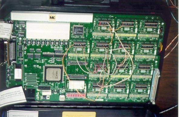
1 MIT Nerd Kit MIT Nerd Kit comes with an array of 16 computational blocks. You can configure these blocks to do anything from computing just ANDs and ORs to being a Beta microprocessor. In addition to those FPGA blocks, there is one breadboard strip, IO block, switches and a few other features of the kit that you need to be know before you get started with the lab asignments that uses the lab kit. Configurable Application Modules Bank of 16 LEDs Detail View I/O connector I0 I1 I2 I3 I4 I5 I6 I7 I8 I9 O0 O1 O2 O3 O4 O5 O6 O7 O8 O9 Each computational block has a 20-pin socket. It s the grey plastic box near the bottom of the computational block with silvery rivets. Each of those rivets is actually a receptacle for the stripped end of a wire. When you run a single wire from one block to another, you are actually making a connection that carries 32 bits. Each of the 32 bits are sent one at a time down the wire, in serial. Thus, we call them serial wires. This is a convenient abstraction which allows you to wire up very complex and powerful circuits without the pain of having to run 32 individual wires for every bussed connection. You can use the same wire to transmit just one bit. Read more on this in Data Transmission section of this document. Switches On the bottom left of the kit right above white breadboard, you will see a row of ten switches. Switches are numbered from right to left (0... 9). Switches 0..7 can be configured to be momentary or push buttons. If a switch is configured to be a momentary button, the wire connected to the switch will carry Vcc only when the switch is pressed. While the same switch configured as a push button will toggle between Vcc and GND at each switch-press. Read about IO block on how to get outputs from a switch. Switch 8: is a push button and can be used to select between free-run and single step mode. When the switch s LED is on, you are in free-run mode. This means that all registers in your circuit are
2 continuously clocked. When the LED is off, you are in single-step mode. This means that the clock is frozen unless you instruct it to go off with switch #9. Switch 9: single-step advance. Pressing this switch while switch 8 is in single-step mode sends exactly one clock pulse to all the registers that use the clock on the kit. This allows you to step through your circuit slowly to facilitate debugging. Switch 9 is functional only when Switch 8 is in off state. Reset button: does a cold boot of the kit. Initializes computational blocks and the underlying logic. NMI button: halts the on-board processor in case it wedges without initializing the computational blocks. LEDs There is a bank of 16 LEDs in each computational block. Different circuit modules use those LEDs in different ways. For instance, echo block uses those LEDs to output each of its 16 Bit input. There are ten LEDs between breadboard and the row of switches. These LEDs can be configured to output the state of the switch (lit = on, not lit = off). You can also use these LEDs to ouput the state of logic level set though DI lines in the IO module. There is one eight digit hex LED display on the first computational block. You can use this LED to display serialized data. Just run the wire that carries serialized data to the second pin from the right. Clocks The kit comes with an internal clock that runs at 20 MHz. A lot of the circuits have implicit clock inputs (Even some combinational circuits have clock inputs!). Most of the clocked circuits use clock that runs slower than the main clock. You can change the frequency of this clock that is used by clocked components by setting Tpd in JTerm. As you learned in class, the critical path is the longest path in a combinational circuit. On these kits, every module has an identical delay, and the critical path is simply the longest path between register elements multiplied by 2. Thus, if you went from a register to an AND gate, to an adder, and back to a register, the critical path length in this example is 6, one for T c-q of the register, one for T pdand, and one fore T pdadd. Your kit will not produce a correct result in free-run mode if you do not set the critical path length correctly. IO Block The white strip on the bottom of the kit is the I/O block. It has pins for power and ground. You will use these if you want certain inputs to be permanently tied to Vcc or GND. You can use DI[0..7] to use the LEDs to output state of a signal (helpful for debugging). Use DO[0..7] to output the state of the switch to a wire that you can run to other part of the circuitry (user inputs to the modules) IO block also has control ROM outputs, to be used when implementing a Beta at the logic level.
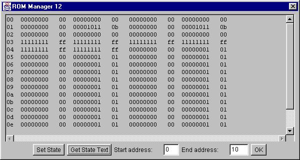
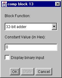
3 Breadboard The upper white block near the bottom of the kit. General breadboarding space. Might be used to add some additional circuit to the lab kit. For example: D/A Data Transmission Data is transferred between different application modules in serialized or non-serialized format. Serialized format is used whenever there is a need to transmit more than one bit of data with a single wire. Each bit is send sequentially in each clock cycle though the same wire. Our implementation transmits the least significant bit first and then works it way up to the most significant bit (total 32 bits). Following waveform graph shows our implementation of serialized transmission. Non serialized format will let you transmit one bit though one wire. Vcc is logical high and GND is logical low. In order to transmit the data you just tie the wire to GND or Vcc depnding on what you Clk Sync Data: 0x1EE want to transmit. Using the Lab Kit You will use a program called JTerm on the workstation to configure the kit. There should be an icon for JTerm on win98 desktop. Start JTerm by double clicking on that icon. If JTerm icon is not on your desktop, change to JTerm folder at an MS-DOS prompt and start JTerm by typying java JTerm. JTerm is your window into the kit. The left half has a GUI which allows you to configure the computational blocks of the kit. You can also hack in the terminal window on the right half, which gives you a direct access to the ROM monitor running on the kit. There is one-to-one correspondence between the buttons you see on the left half of JTerm and the computational block array on the kit. In JTerm, when you click on a button labelled comp block n, you are presented with a dialog box. The top pulldown menu in this dialog box allows you to set the function of the block. The constant field in this dialog sets the number that is output on the constant generator port (if applicable). State button is active for some of the circuit modules only. If you are using any of those modules (eg. ROM, RAM, Const generator), select the function from the pulldown menu. Click on OK. When you go to the same block configuration for the second time, the
4 state button will be enabled. When you click on State, relevant state configuration dialog will show up. You will check on Display binary Input for Display block only. Display block will not function if you forget to check this option. General work flow 1 Start JTerm 2 Click on open port (button on bottom left) 3 Make sure the kit is connected to the host, and power it on 4 Wait until the kit finishes its power-on initialization (about seconds) 5 Click on computational block buttons to set their functions. 6 Adjust kit switches and clocking according to your design 7 Click Configure Kit. You can watch what JTerm is doing by looking at the MS-DOS window that you used to start JTerm. Configuration takes about a minute the first time, but after that, as long as Use Dirty Bits is selected, small changes take less than a second to update. 8 After stuff stops scrolling by on the MS-DOS window, your kit is now ready to use. 9 If you are using free-run circuit, don t forget to set appropriate critical-path. 10 If you change any of the configurations (with the exception of setting state, clocking, and switches ), you MUST hit Configure Kit again before the changes are uploaded to the kit. 11 If you power down or reset your kit without restarting JTerm, you will have to clear the Use Dirty Bits box for the first configuration, because the dirty bits maintained by JTerm internally are now all invalid. Be sure to reset Use Dirty Bits after the first configuration for faster configuration updates. Revision History: Omprakash Gnawali, Spring 99 Andrew Huang, Fall 98

5 JTerm Screen Shots
6
Drexel University Electrical and Computer Engineering Department ECE 200 Intelligent Systems Spring Lab 1. Pencilbox Logic Designer
 Lab 1. Pencilbox Logic Designer Introduction: In this lab, you will get acquainted with the Pencilbox Logic Designer. You will also use some of the basic hardware with which digital computers are constructed
Copyright 2011 R.S.R. Electronics, Inc. All rights reserved. 04/11. Ver. 1.0web
 For XILINX WebPack Copyright 2011 R.S.R. Electronics, Inc. All rights reserved. 04/11 Ver. 1.0web 1 Table of Contents 1.0 INTRODUCTION...3 2.0 GENERAL DESCRIPTION...5 3.0 BRIEF DESCRIPTION Of PLDT-3 BOARD...6
Massachusetts Institute of Technology Department of Electrical Engineering and Computer Science Introductory Digital Systems Laboratory
 Massachusetts Institute of Technology Department of Electrical Engineering and Computer Science 6.111 -- Introductory Digital Systems Laboratory NUBUS LABORATORY KIT For your pleasure and convenience,
Digital Electronics & Computer Engineering (E85)
") Digital Electronics & Computer Engineering (E85) Lab 4: Thunderbird Turn Signal Introduction In this lab, you will design a finite state machine to control the taillights of a 1965 Ford Thunderbird 1 and
Digital Electronics & Computer Engineering (E85) Lab 4: Thunderbird Turn Signal Introduction In this lab, you will design a finite state machine to control the taillights of a 1965 Ford Thunderbird 1 and
7 8 9 C. PRELAB REQUIREMENTS You must adhere to the Lab Rules and Policies document for every lab.
 Page 1/ Revision 1 OBJECTIVES To understand how a keypad functions as a raster scan input device and to learn how to interface a keypad to a microprocessor. Further explore and understand the implementation
Microcomputer System Design
 Microcomputer System Design COE305 Lab. What is a Microprocessor? A microprocessor is a multipurpose, clockdriven, register-based electronic device that reads binary instructions from a storage device
University of California at Berkeley College of Engineering Department of Electrical Engineering and Computer Science. EECS 150 Spring 2000
 University of California at Berkeley College of Engineering Department of Electrical Engineering and Computer Science EECS 150 Spring 2000 Lab 1 Introduction to Xilinx Design Software 1 Objectives In this
_ V Intel 8085 Family In-Circuit Emulation. Contents. Technical Notes
 _ V9.12. 225 Technical Notes Intel 8085 Family In-Circuit Emulation This document is intended to be used together with the CPU reference manual provided by the silicon vendor. This document assumes knowledge
ECSE-323 Digital System Design. Lab #1 Using the Altera Quartus II Software Fall 2008
 1 ECSE-323 Digital System Design Lab #1 Using the Altera Quartus II Software Fall 2008 2 Introduction. In this lab you will learn the basics of the Altera Quartus II FPGA design software through following
PAD ANALOG / DIGITAL TRAINER OPERATOR S MANUAL
 PAD - 234 ANALOG / DIGITAL TRAINER OPERATOR S MANUAL Rev. 7/94 GENERAL OPERATING PROCEDURES 1. This manual should be read thoroughly before engaging in any experimentation. 2. As a general rule, NEVER
University of California at Berkeley College of Engineering Department of Electrical Engineering and Computer Science
 University of California at Berkeley College of Engineering Department of Electrical Engineering and Computer Science EECS 150 Fall 2000 Original Lab By: J.Wawrzynek and N. Weaver Edited by B. Choi, R.
Name EGR 2131 Lab #6 Number Representation and Arithmetic Circuits
 Name EGR 2131 Lab #6 Number Representation and Arithmetic Circuits Equipment and Components Quartus software and Altera DE2-115 board PART 1: Number Representation in Microsoft Calculator. First, let s
8254 is a programmable interval timer. Which is widely used in clock driven digital circuits. with out timer there will not be proper synchronization
 8254 is a programmable interval timer. Which is widely used in clock driven digital circuits. with out timer there will not be proper synchronization between two devices. So it is very useful chip. The
NAME EET 2259 Lab 3 The Boolean Data Type
 NAME EET 2259 Lab 3 The Boolean Data Type OBJECTIVES - Understand the differences between numeric data and Boolean data. -Write programs using LabVIEW s Boolean controls and indicators, Boolean constants,
Lab 1: Introduction to Verilog HDL and the Xilinx ISE
 EE 231-1 - Fall 2016 Lab 1: Introduction to Verilog HDL and the Xilinx ISE Introduction In this lab simple circuits will be designed by programming the field-programmable gate array (FPGA). At the end
Training Kit for HP 1660/70 Series Logic Analyzers
 Training Guide Publication Number E2433-97034 First Edition, November 1997 For Safety information, Warranties, and Regulatory information, see the pages behind the Index. Copyright Hewlett-Packard Company
DS1870 LDMOS BIAS CONTROLLER EV KIT
 GENERAL DESCRIPTION The DS1870 EV Kit provides hardware and Window s compatible software to simplify the evaluation of the DS1870 LDMOS Bias Controller. FEATURES Includes test socket for solderless connectivity
Chapter Operation Pinout Operation 35
 68000 Operation 35 Chapter 6 68000 Operation 6-1. 68000 Pinout We will do no construction in this chapter; instead, we will take a detailed look at the individual pins of the 68000 and what they do. Fig.
Experiment 9: Binary Arithmetic Circuits. In-Lab Procedure and Report (30 points)
") ELEC 2010 Laboratory Manual Experiment 9 In-Lab Procedure Page 1 of 7 Experiment 9: Binary Arithmetic Circuits In-Lab Procedure and Report (30 points) Before starting the procedure, record the table number
ELEC 2010 Laboratory Manual Experiment 9 In-Lab Procedure Page 1 of 7 Experiment 9: Binary Arithmetic Circuits In-Lab Procedure and Report (30 points) Before starting the procedure, record the table number
University of California, Davis Department of Electrical and Computer Engineering. Lab 1: Implementing Combinational Logic in the MAX10 FPGA
 1 University of California, Davis Department of Electrical and Computer Engineering EEC180B DIGITAL SYSTEMS II Winter Quarter 2018 Lab 1: Implementing Combinational Logic in the MAX10 FPGA Objective: This
Programmable Logic Design I
 Programmable Logic Design I Introduction In labs 11 and 12 you built simple logic circuits on breadboards using TTL logic circuits on 7400 series chips. This process is simple and easy for small circuits.
EE 231 Fall Lab 1: Introduction to Verilog HDL and Altera IDE
 Lab 1: Introduction to Verilog HDL and Altera IDE Introduction In this lab you will design simple circuits by programming the Field-Programmable Gate Array (FPGA). At the end of the lab you should be able
Getting Started with STK200 Dragon
 Getting Started with STK200 Dragon Introduction This guide is designed to get you up and running with main software and hardware. As you work through it, there could be lots of details you do not understand,
CHAPTER 1 Introduction of the tnano Board CHAPTER 2 tnano Board Architecture CHAPTER 3 Using the tnano Board... 8
 CONTENTS CHAPTER 1 Introduction of the tnano Board... 2 1.1 Features...2 1.2 About the KIT...4 1.3 Getting Help...4 CHAPTER 2 tnano Board Architecture... 5 2.1 Layout and Components...5 2.2 Block Diagram
ECEN 449: Microprocessor System Design Department of Electrical and Computer Engineering Texas A&M University. Laboratory Exercise #1 Using the Vivado
 ECEN 449: Microprocessor System Design Department of Electrical and Computer Engineering Texas A&M University Prof. Sunil P Khatri (Lab exercise created and tested by Ramu Endluri, He Zhou, Andrew Douglass
and 32 bit for 32 bit. If you don t pay attention to this, there will be unexpected behavior in the ISE software and thing may not work properly!
 This tutorial will show you how to: Part I: Set up a new project in ISE 14.7 Part II: Implement a function using Schematics Part III: Simulate the schematic circuit using ISim Part IV: Constraint, Synthesize,
A B A+B
 ECE 25 Lab 2 One-bit adder Design Introduction The goal of this lab is to design a one-bit adder using programmable logic on the BASYS board. Due to the limitations of the chips we have in stock, we need
CHAPTER TWELVE - Memory Devices
 CHAPTER TWELVE - Memory Devices 12.1 6x1,024 = 16,384 words; 32 bits/word; 16,384x32 = 524,288 cells 12.2 16,384 addresses; one per word. 12.3 2 16 = 65,536 words = 64K. Thus, memory capacity is 64Kx4.
If I wanted to connect an LED and little light bulb and have them switch on and off with one switch, my schematic would look like the one below.
 Relays Relays are great tools for turning on and off entire circuits, either with a small control switch, or with a microcontroller like the Arduino. To understand how relays are useful and how to control
Propeller Activity Board (#32910)
") Web Site: www.parallax.com Forums: forums.parallax.com Sales: sales@parallax.com Technical: support@parallax.com Office: (916) 624-8333 Fax: (916) 624-8003 Sales: (888) 512-1024 Tech Support: (888) 997-8267
Web Site: www.parallax.com Forums: forums.parallax.com Sales: sales@parallax.com Technical: support@parallax.com Office: (916) 624-8333 Fax: (916) 624-8003 Sales: (888) 512-1024 Tech Support: (888) 997-8267
UNIVERSITY OF CALIFORNIA, DAVIS Department of Electrical and Computer Engineering. EEC180A DIGITAL SYSTEMS I Winter 2015
 UNIVERSITY OF CALIFORNIA, DAVIS Department of Electrical and Computer Engineering EEC180A DIGITAL SYSTEMS I Winter 2015 LAB 1: Introduction to Quartus II Schematic Capture and ModelSim Simulation This
Evaluates: DS28E80. DS28E80 Evaluation System. General Description. Benefits and Features. EV Kit Contents
 General Description The DS28E80 evaluation system (EV system) consists of a single evaluation kit (EV kit) that includes a package of five DS28E80 devices in a 6-pin TDFN package, a DS9120Q+ socket board
The UNIVERSITY of NORTH CAROLINA at CHAPEL HILL
 The UNIVERSITY of NORTH CAROLINA at CHAPEL HILL Comp 541 Digital Logic and Computer Design Prof. Montek Singh Fall 2016 Lab #5: Working with the boards! Issued Wed 9/21/16; Due Wed 9/28/16 (submit by 11:59pm)
University of California at Berkeley College of Engineering Department of Electrical Engineering and Computer Sciences. EECS 150 Spring 2000
 University of California at Berkeley College of Engineering Department of Electrical Engineering and Computer Sciences EECS 150 Spring 2000 Lab #8: EPROMs This lab is to be completed with a project partner.
Digital Electronics & Computer Engineering (E85)
") Digital Electronics & Computer Engineering (E85) Lab 5: 32-bit ALU Introduction In this lab, you will build the 32-bit Arithmetic Logic Unit (ALU) that is described in your book in Section 4.5. Your ALU
Digital Electronics & Computer Engineering (E85) Lab 5: 32-bit ALU Introduction In this lab, you will build the 32-bit Arithmetic Logic Unit (ALU) that is described in your book in Section 4.5. Your ALU
University of California at Berkeley College of Engineering Department of Electrical Engineering and Computer Science
 University of California at Berkeley College of Engineering Department of Electrical Engineering and Computer Science EECS 150 Spring 2002 Original Lab By: J.Wawrzynek and N. Weaver Later revisions by
User s Guide. LA5034 Operation Manual
 User s Guide LA5034 Operation Manual Content General safety summary... I Introduction... II Chapter 1 Getting started... 1 System Requirements... 2 Installing Hardware... 3 Installing Software... 6 User
Arduino Micro Breadboard Laboratory Interface Processor (Micro BLIP) User Manual
 User Manual") Arduino Micro Breadboard Laboratory Interface Processor (Micro BLIP) MicroBLIP circuit board v2.0 Operating System v2.0.0 1/22/2019 User Manual 2 1 Setup and Operation 1.1 Introduction For the past ten
Arduino Micro Breadboard Laboratory Interface Processor (Micro BLIP) MicroBLIP circuit board v2.0 Operating System v2.0.0 1/22/2019 User Manual 2 1 Setup and Operation 1.1 Introduction For the past ten
PSIM Tutorial. How to Use SCI for Real-Time Monitoring in F2833x Target. February Powersim Inc.
 PSIM Tutorial How to Use SCI for Real-Time Monitoring in F2833x Target February 2013-1 - With the SimCoder Module and the F2833x Hardware Target, PSIM can generate ready-to-run codes for DSP boards that
Bill of Materials: Turn Off the Lights Reminder PART NO
 Turn Off the Lights Reminder PART NO. 2209650 Have you ever woke up early in the morning to find out that the kids (or adults) in your home forgot to turn off the lights? I've had that happen a number
Introduction to LogicWorks (Version 5) by: Kevin Su
 by: Kevin Su") Introduction to LogicWorks (Version 5) January 24, 2005 by: Kevin Su 0. INTRODUCTION These notes are meant as a supplement for students taking CS 2513 (Computer Organizaition I ), especially for those
Introduction to LogicWorks (Version 5) January 24, 2005 by: Kevin Su 0. INTRODUCTION These notes are meant as a supplement for students taking CS 2513 (Computer Organizaition I ), especially for those
Pre-Lab: Part 1 Using The Development Environment. Purpose: Minimum Parts Required: References: Handouts:
 Purpose: Minimum Parts Required: References: Handouts: Laboratory Assignment Number 1 for Mech 143/ELEN123 Due by 5:00pm in lab box on Friday, April 19, 2002 Pre-Lab due by 5:00pm in lab box on Tuesday,
Boise State University Digital Systems Laboratory
 by S. M. Loo, Arlen Planting Department of Electrical and Computer Engineering Boise State University First Released: Spring 2005 with ISE 6.3i Updated: Fall 2006 with ISE 8.1i Updated: Spring 2009 with
EE 390 Lab Manual, EE Department, KFUPM. Experiment #7. Introduction to Flight86 Microprocessor Trainer and Application Board
 Experiment #7 Introduction to Flight86 Microprocessor Trainer and Application Board 7.0 Objectives: The objective of this experiment is to introduce the Flight86 Microprocessor training kit and application
ISP Engineering Kit Model 300
 TM ISP Engineering Kit Model 300 December 2013 Model 300 Overview The Model 300 programmer supports JTAG programming of all Lattice devices that feature non-volatile configuration elements. The Model 300
Freeze the Dizz Jameco Part No
 Freeze the Dizz Jameco Part No. 2161431 This project is based on a children s arcade game. Twenty LEDs are placed on a ring and each takes turn to light up forming a rotating light spot. If a push-button
INSTALLATION AND OPERATION MANUAL FOR ACC 070 COMM LINK RS485 TO PC INTERFACE AND PRISM SOFTWARE
 SenTech Corporation 5745 Progress Road Indianapolis, Indiana 46241 888/248-1988 FAX 317/248-2014 INSTALLATION AND OPERATION MANUAL FOR ACC 070 COMM LINK RS485 TO PC INTERFACE AND PRISM SOFTWARE ii APPLICABILITY
Goal: We want to build an autonomous vehicle (robot)
") Goal: We want to build an autonomous vehicle (robot) This means it will have to think for itself, its going to need a brain Our robot s brain will be a tiny computer called a microcontroller Specifically
Goal: We want to build an autonomous vehicle (robot) This means it will have to think for itself, its going to need a brain Our robot s brain will be a tiny computer called a microcontroller Specifically
Getting Started with the HCS12 IDE
 Getting Started with the HCS12 IDE B. Ackland June 2015 This document provides basic instructions for installing and using the MiniIDE Integrated Development Environment and the Java based HCS12 simulator.
CPLD/FPGA Development System
 Chapter 1 CPLD/FPGA Development System As shown in Figure 1-1, CPLD (Complex Programmable Logic Device) and FPGA (Field-Programmable Gate Array) are the programmable logic devices (PLDs) whose internal
AVR Board Setup General Purpose Digital Output
 ECE3411 Fall 2016 Lab 2a. AVR Board Setup General Purpose Digital Output Marten van Dijk, Chenglu Jin Department of Electrical & Computer Engineering University of Connecticut Email: {marten.van_dijk,
EET 1131 Lab #7 Arithmetic Circuits
 Name Equipment and Components Safety glasses ETS-7000 Digital-Analog Training System Integrated Circuits: 7483, 74181 Quartus II software and Altera DE2-115 board Multisim simulation software EET 1131
ECEN 449: Microprocessor System Design Department of Electrical and Computer Engineering Texas A&M University. Laboratory Exercise #1 Using the Vivado
 ECEN 449: Microprocessor System Design Department of Electrical and Computer Engineering Texas A&M University Prof. Sunil P. Khatri Lab exercise created and tested by: Abbas Fairouz, Ramu Endluri, He Zhou,
GammaTron USB Module
 GammaTron USB Module Product ID. : 710 Board Rev. : 1.00 Date : June 24, 2007 Firmware Rev. : 1.11 Beta Innovations (c) 2006 http://www.betainnovations.com Table of Contents Main Features...5 Introduction...6
Finite State Machine Lab
 Finite State Machine Module: Lab Procedures Goal: The goal of this experiment is to reinforce state machine concepts by having students design and implement a state machine using simple chips and a protoboard.
Configuring APEX 20K, FLEX 10K & FLEX 6000 Devices
 Configuring APEX 20K, FLEX 10K & FLEX 6000 Devices December 1999, ver. 1.02 Application Note 116 Introduction APEX TM 20K, FLEX 10K, and FLEX 6000 devices can be configured using one of six configuration
The UNIVERSITY of NORTH CAROLINA at CHAPEL HILL
 The UNIVERSITY of NORTH CAROLINA at CHAPEL HILL Comp 541 Digital Logic and Computer Design Spring 2015 Lab #5: Working with the boards! Issued Wed 2/4/15; Due Wed 2/11/15 (submit by 11:59pm) This lab introduces
Introduction to Computer Engineering (E114)
") Introduction to Computer Engineering (E114) Lab 1: Full Adder Introduction In this lab you will design a simple digital circuit called a full adder. You will then use logic gates to draw a schematic for
Introduction to Computer Engineering (E114) Lab 1: Full Adder Introduction In this lab you will design a simple digital circuit called a full adder. You will then use logic gates to draw a schematic for
University of Hawaii EE 361L. Getting Started with Spartan 3E Digilent Basys2 Board. Lab 4.1
 University of Hawaii EE 361L Getting Started with Spartan 3E Digilent Basys2 Board Lab 4.1 I. Test Basys2 Board Attach the Basys2 board to the PC or laptop with the USB connector. Make sure the blue jumper
University of Massachusetts Amherst Computer Systems Lab 2 (ECE 354) Spring Lab 1: Using Nios 2 processor for code execution on FPGA
 Spring Lab 1: Using Nios 2 processor for code execution on FPGA") University of Massachusetts Amherst Computer Systems Lab 2 (ECE 354) Spring 2007 Lab 1: Using Nios 2 processor for code execution on FPGA Objectives: After the completion of this lab: 1. You will understand
University of Massachusetts Amherst Computer Systems Lab 2 (ECE 354) Spring 2007 Lab 1: Using Nios 2 processor for code execution on FPGA Objectives: After the completion of this lab: 1. You will understand
Table 1 - SDIO Pinout. Pin SD 4-bit Mode SD 1-bit Mode SPI Mode. 1 CD/DAT3 Data Line CS Card Select
 Quick Start Guide Computer System Requirements Supported Systems Operating System: Windows 7/8/10 USB:USB 2.0 and later Minimum Requirements Processor: Core i5 at 2.7 GHz RAM: 4 GB Free Hard Disk Space
Programmable Logic Design I
 Programmable Logic Design I Read through each section completely before starting so that you have the benefit of all the directions. Put on a grounded wrist strap (cf. Getting Started) before touching
ESE 150 Lab 07: Digital Logic
 LAB 07 In this lab we will do the following: 1. Investigate basic logic operations (AND, OR, INV, XOR) 2. Implement an ADDER on an FPGA 3. Implement a simple Finite- State Machine on an FPGA Background:
KIT-VR4120-TP. User's Manual (Rev.1.01) RealTimeEvaluator
 RealTimeEvaluator") User's Manual (Rev.1.01) RealTimeEvaluator Software Version Up * The latest RTE for Win32 (Rte4win32) can be down-loaded from following URL. http://www.midas.co.jp/products/download/english/program/rte4win_32.htm
User's Manual (Rev.1.01) RealTimeEvaluator Software Version Up * The latest RTE for Win32 (Rte4win32) can be down-loaded from following URL. http://www.midas.co.jp/products/download/english/program/rte4win_32.htm
4. Configuring Cyclone II Devices
 4. Configuring Cyclone II Devices CII51013-2.0 Introduction Cyclone II devices use SRAM cells to store configuration data. Since SRAM memory is volatile, configuration data must be downloaded to Cyclone
REQUIRED MATERIALS Reread Lab Rules and Policies document EEL 3744 (upad and upad Proto Base) DAD/NAD Analog Discovery board PRELAB REQUIREMENTS
 DAD/NAD Analog Discovery board PRELAB REQUIREMENTS") Page 1/ Lab 2: GPIO Expansion (LEs and Keypad) 3-Feb-17 OJETIVES In this lab you will perform the first of several physical expansions of your EEL37 board, the up Proto ase, by adding LE and keypad circuits.
Page 1/ Lab 2: GPIO Expansion (LEs and Keypad) 3-Feb-17 OJETIVES In this lab you will perform the first of several physical expansions of your EEL37 board, the up Proto ase, by adding LE and keypad circuits.
EECS 140 Laboratory Exercise 4 3-to-11 Counter Implementation
 EECS 140 Laboratory Exercise 4 3-to-11 Counter Implementation 1. Objectives A. To apply knowledge of combinatorial design. B. Gain expertise in designing and building a simple combinatorial circuit This
PUSH BUTTON. Revision Class. Instructor / Professor LICENSE
 CME-11E9 EVBU LAB EXPERIMENT PUSH BUTTON Revision 04.02.11 Class Instructor / Professor LICENSE You may use, copy, modify and distribute this document freely as long as you include this license and the
TECH 3821 Lab #2 Relay Driver with Computer Control
 TECH 3821 Lab #2 Relay Driver with Computer Control Name: Background: One of the most basic controls in industry is the ability to turn things on and off. As we saw in Lab #1, a relay is often used to
DOMAIN TECHNOLOGIES INC. Users Guide Version 2.0 SB-USB2. Emulator
 INC. Users Guide Version 2.0 SB-USB2 Emulator Table of Contents 1 INTRODUCTION... 3 1.1 Features... 3 1.2 Package Contents... 4 1.3 Related Components... 4 2 INSTALLATION... 4 3 INTEGRATION WITH LSI LOGIC
Avnet Zynq Mini Module Plus Embedded Design
 Avnet Zynq Mini Module Plus Embedded Design Version 1.0 May 2014 1 Introduction This document describes a Zynq standalone OS embedded design implemented and tested on the Avnet Zynq Mini Module Plus. 2
Intro to Digital Logic, Lab 5 Sequential Logic. Lab Objectives. Assigned Task Mapping sequential logic to the FPGA
 Intro to Digital Logic, Lab 5 Sequential Logic Lab Objectives Now that we have mastered combinational logic, it is time to figure out sequential circuits. In this lab you will download a premade design
3. The MC6802 MICROPROCESSOR
 3. The MC6802 MICROPROCESSOR This chapter provides hardware detail on the Motorola MC6802 microprocessor to enable the reader to use of this microprocessor. It is important to learn the operation and interfacing
The UNIVERSITY of NORTH CAROLINA at CHAPEL HILL
 The UNIVERSITY of NORTH CAROLINA at CHAPEL HILL Comp 541 Digital Logic and Computer Design Spring 2016 Lab #1: Getting Started Issued Wed. 1/13/16; Due Wed. 1/20/16 (11:59pm) This lab assignment consists
E85: Digital Design and Computer Engineering Lab 1: Electrical Characteristics of Logic Gates
 E85: Digital Design and Computer Engineering Lab 1: Electrical Characteristics of Logic Gates Objective The purpose of this lab is to become comfortable with logic gates as physical objects, to interpret
CSEE W4840 Embedded System Design Lab 1
 CSEE W4840 Embedded System Design Lab 1 Stephen A. Edwards Due January 31, 2008 Abstract Learn to use the Altera Quartus development envrionment and the DE2 boards by implementing a small hardware design
E3940 Microprocessor Systems Laboratory. Introduction to the Z80
 E3940 Microprocessor Systems Laboratory Introduction to the Z80 Andrew T. Campbell comet.columbia.edu/~campbell campbell@comet.columbia.edu E3940 Microprocessor Systems Laboratory Page 1 Z80 Laboratory
CSEE W4840 Embedded System Design Lab 1
 CSEE W4840 Embedded System Design Lab 1 Stephen A. Edwards Due February 2, 2009 Abstract Learn to use the Altera Quartus development envrionment and the DE2 boards by implementing a small hardware design
EECS 150 Homework 7 Solutions Fall (a) 4.3 The functions for the 7 segment display decoder given in Section 4.3 are:
 4.3 The functions for the 7 segment display decoder given in Section 4.3 are:") Problem 1: CLD2 Problems. (a) 4.3 The functions for the 7 segment display decoder given in Section 4.3 are: C 0 = A + BD + C + BD C 1 = A + CD + CD + B C 2 = A + B + C + D C 3 = BD + CD + BCD + BC C 4
Problem 1: CLD2 Problems. (a) 4.3 The functions for the 7 segment display decoder given in Section 4.3 are: C 0 = A + BD + C + BD C 1 = A + CD + CD + B C 2 = A + B + C + D C 3 = BD + CD + BCD + BC C 4
ice40 Ultra Self-Learning IR Remote User s Guide
 ice40 Ultra Self-Learning IR Remote User s Guide June 2014 UG74_1.0 Introduction ice40 Ultra Self-Learning IR Remote User s Guide This guide describes how to use the ice40 Ultra Mobile Development Platform
NIOS CPU Based Embedded Computer System on Programmable Chip
 1 Objectives NIOS CPU Based Embedded Computer System on Programmable Chip EE8205: Embedded Computer Systems This lab has been constructed to introduce the development of dedicated embedded system based
Lecture-55 System Interface:
 Lecture-55 System Interface: To interface 8253 with 8085A processor, CS signal is to be generated. Whenever CS =0, chip is selected and depending upon A 1 and A 0 one of the internal registers is selected
1/Build a Mintronics: MintDuino
 1/Build a Mintronics: The is perfect for anyone interested in learning (or teaching) the fundamentals of how micro controllers work. It will have you building your own micro controller from scratch on
4408 Digital Audio 8x1 Switch
 Digital Audio x Switch Contents Introduction 2 2 Installation 2. Signal I/O and control pinout 5 2.2 Crosspoint control 7 3 Configuration 3. Input set-up 2 3.2 Configuring an x switcher 3 3.3 Source expansion
CPE/EE 421/521 Fall 2004 Chapter 4 The CPU Hardware Model. Dr. Rhonda Kay Gaede UAH. The CPU Hardware Model - Overview
 CPE/EE 421/521 Fall 2004 Chapter 4 The 68000 CPU Hardware Model Dr. Rhonda Kay Gaede UAH Fall 2004 1 The 68000 CPU Hardware Model - Overview 68000 interface Timing diagram Minimal configuration using the
EE 271 Final Project - Towers of Hanoi
 EE 271 Final Project - Towers of Hanoi Siyu Jian, Michael Molina, Kendrick Tang December 6, 2012 We all worked Abstract In this project, we designed and implemented the game of tower of Hanoi on the DE1
KIT-V850E2/MN4-TP-H. User s Manual (Rev. 1.01) RealTimeEvaluator
 RealTimeEvaluator") KIT-V850E2/MN4-TP-H User s Manual (Rev. 1.01) RealTimeEvaluator Software Version Up * The latest RTE for Win32 (Rte4win32) can be down-loaded from following URL. http://www.midas.co.jp/products/download/english/program/rte4win_32.htm
KIT-V850E2/MN4-TP-H User s Manual (Rev. 1.01) RealTimeEvaluator Software Version Up * The latest RTE for Win32 (Rte4win32) can be down-loaded from following URL. http://www.midas.co.jp/products/download/english/program/rte4win_32.htm
CSEE W4840 Embedded System Design Lab 1
 CSEE W4840 Embedded System Design Lab 1 Stephen A. Edwards Due February 3, 2011 Abstract Learn to use the Altera Quartus development envrionment and the DE2 boards by implementing a small hardware design
ENEE245 Digital Circuits and Systems Lab Manual
 ENEE245 Digital Circuits and Systems Lab Manual Department of Engineering, Physical & Computer Sciences Montgomery College Version 1.1 Copyright Prof. Lan Xiang (Do not distribute without permission) 1
CS4141 IDL Notes. I. Quick Overview of IDL Prototyping Unit
 CS4141 IDL Notes IDL-800 Prototyping System The IDL-800 logic panels are powerful tools for any logic designer. They enable a wide range of IC s to be used in a breadboard experiment. I. Quick Overview
EE 354 August 1, 2017 Assembly of the AT89C51CC03 board
 EE 354 August 1, 2017 Assembly of the AT89C51CC03 board The AT89C51CC03 board comes as a kit which you must put together. The kit has the following parts: No. ID Description 1 1.5" x 3.25" printed circuit
REQUIRED MATERIALS Reread Lab Rules and Policies document EEL 3744 (upad and upad Proto Base) Digilent Analog Discovery (DAD) PRELAB REQUIREMENTS
 Digilent Analog Discovery (DAD) PRELAB REQUIREMENTS") Page 1/ Lab 2: GPIO Expansion (LEs and Keypad) 2-May-1 OJETIVES In this lab you will perform the first of several physical expansions of your EEL37 board, the up Proto ase, by adding LE and keypad circuits.
Page 1/ Lab 2: GPIO Expansion (LEs and Keypad) 2-May-1 OJETIVES In this lab you will perform the first of several physical expansions of your EEL37 board, the up Proto ase, by adding LE and keypad circuits.
Quick Tutorial for Quartus II & ModelSim Altera
 Quick Tutorial for Quartus II & ModelSim Altera By Ziqiang Patrick Huang Hudson 213c Ziqiang.huang@duke.edu Download & Installation For Windows or Linux users : Download Quartus II Web Edition v13.0 (ModelSim
E85: Digital Design and Computer Architecture J. Spjut and R. Wang Spring 2014
 E85: Digital Design and Computer Architecture J. Spjut and R. Wang Spring 2014 Lab 1: Full Adder Introduction In this lab you will design a simple digital circuit called a full adder. Along the way, you
REQUIRED MATERIALS Reread Lab Rules and Policies document EEL 3744 (upad and upad Proto Base) Digilent Analog Discovery (DAD) PRELAB REQUIREMENTS
 Digilent Analog Discovery (DAD) PRELAB REQUIREMENTS") Page 1/ Lab 2: GPIO Expansion (LEs and Keypad) 2-Jan-1 OJETIVES In this lab you will perform the first of several physical expansions of your EEL3744 board, the up Proto ase, by adding LE and keypad circuits.
Page 1/ Lab 2: GPIO Expansion (LEs and Keypad) 2-Jan-1 OJETIVES In this lab you will perform the first of several physical expansions of your EEL3744 board, the up Proto ase, by adding LE and keypad circuits.
475 Electronics for physicists Introduction to FPGA programming
 475 Electronics for physicists Introduction to FPGA programming Andrej Seljak, Gary Varner Department of Physics University of Hawaii at Manoa November 18, 2015 Abstract Digital circuits based on binary
COS 116 The Computational Universe Laboratory 7: Digital Logic I
 COS 116 The Computational Universe Laboratory 7: Digital Logic I In this lab you ll construct simple combinational circuits in software, using a simulator, and also in hardware, with a breadboard and silicon
Halloween Pumpkinusing. Wednesday, October 17, 12
 Halloween Pumpkinusing Blink LED 1 What you will need: 1 MSP-EXP430G2 1 3 x 2 Breadboard 3 560 Ohm Resistors 3 LED s (in Red Color Range) 3 Male to female jumper wires 1 Double AA BatteryPack 2 AA Batteries
EE261 Computer Project 1: Using Mentor Graphics for Digital Simulation
 EE261 Computer Project 1: Using Mentor Graphics for Digital Simulation Introduction In this project, you will begin to explore the digital simulation tools of the Mentor Graphics package available on the
ANADOLU UNIVERSITY DEPARTMENT OF ELECTRICAL AND ELECTRONICS ENGINEERING. EEM Digital Systems II
 ANADOLU UNIVERSITY DEPARTMENT OF ELECTRICAL AND ELECTRONICS ENGINEERING EEM 334 - Digital Systems II LAB 1 - INTRODUCTION TO XILINX ISE SOFTWARE AND FPGA 1. PURPOSE In this lab, after you learn to use