Russound Controllers. RNET Protocol & Specifications RS-232 Communication. Document version
|
|
|
- Gillian Townsend
- 6 years ago
- Views:
Transcription
1 Russound Controllers RNET Protocol & Specifications RS-232 Communication Document version
2 Quick Reference Guide Feature CAS44 CAA66 CAM6.6 CAV6.6 Pg. Keypad Events 13 Source Control Events 14 Set Zone On/Off 19 Set All Zones On 19 Set All Zones Off 19 Zone Source 20 Zone Volume 21 Bass 22 Treble 23 Loudness 24 Balance 25 Turn On Volume 26 Background Color 27 Do Not Disturb 28 Party Mode 29 All Zone Info 30 Displaying a String 31 Display Messages 33 = Partially Supported Feature = Fully Supported Feature 2
3 1 INTRODUCTION OVERVIEW COM PORT COM SETTINGS CONNECTOR TYPE / PIN-OUT RNET MESSAGE PACKET FORMAT MESSAGE HEADER Start of Message Character Target Device ID Target Controller ID Target Zone (Port) ID Target Keypad ID Source Device ID Source Controller ID Source Zone (Port) ID Source Keypad ID Message Type MESSAGE BODY The Invert Character Event Messages Data Messages MESSAGE TRAILER Checksum End of Message Character BUTTONS AND KEYCODES KEYPAD EVENTS SOURCE CONTROL EVENTS USING REQUEST MESSAGES ZONES ON/OFF Set State Get State Set All Zones On/Off State SOURCE SELECT Set Source Get Source VOLUME SELECT Set Volume Get Volume BASS Bass Up/Bass Down Set Bass Get Bass TREBLE Treble Up/Treble Down Set Treble Get Treble LOUDNESS Loudness Toggle On/Off Set Loudness Get Loudness BALANCE Balance Left or Balance Right Set Balance
4 7.7.3 Get Balance TURN ON VOLUME Increase or Decrease Turn On Volume Set Turn On Volume Get Turn On Volume BACKGROUND COLOR Background Color Off/Amber/Green toggle Set Background Color Get Background Color DO NOT DISTURB Do Not Disturb On/Off Toggle Set Do Not Disturb Get Do Not Disturb PARTY MODE Party Mode On, Party Mode Master, and Party Mode Off Set Party Mode Get Party Mode GET ALL ZONE INFO Get State DISPLAYING A STRING ON ALL KEYPADS ON A SPECIFIC KEYPAD DISPLAY MESSAGES READING DIRECT DISPLAY FEEDBACK READING SOURCE BROADCAST DISPLAY FEEDBACK READING MULTI-FIELD BROADCAST DISPLAY FEEDBACK MESSAGES USING THE ACKNOWLEDGE MESSAGE (HANDSHAKING) ASCII CHARACTER SET TO HEX CONVERSION CHART RUSSOUND CONTROLLERS RS-232 HEX CODE LISTING
5 1 Introduction This document describes how to control and interpret data from Russound controllers. Remote access is provided through the RS-232 serial port found on the front (CAV only) or rear of the controller using the following RNET communications protocol. It is assumed that the reader is familiar with the features and operation of the controller being used. All commands use Hexadecimal or HEX values. In descriptive text these are indicated by preceding the value with a 0x. Zero-based values are also used in certain areas and are noted as such. This means that a value of 0x00 = 1, 0x01 = 2, and 0x02 = 3 etc Throughout this document all bytes within message packets not in bold must be referenced exactly as they appear. 2 Overview Russound controllers use a comprehensive communications protocol called RNET which has been extended to the RS-232 port. Through this port, virtually all aspects of the device operation can be performed. This document provides detailed descriptions of messages required to perform basic device operation, as well as instructions on how to interpret display feedback messages. 3 COM Port 3.1 COM Settings baud rate 1 Start bit 1 Stop bit No flow control No parity 3.2 Connector Type / Pin-out Connector: Female DB-9 Pin 1: NC Pin 2: Transmit Pin 3: Receive Pin 4: NC Pin 5: Ground Pin 6: NC Pin 7: NC Pin 8: NC Pin 9: NC 5
6
7 4 RNET Message Packet Format Header Body Trailer 0xF0 Target Device ID Source Device ID Type Body Checksum 0xF7 Every RNET message has a consistent format. There are three major components; the Message Header, Message Body and Message Trailer. Each of these is explained here in some detail. There are several special characters used in this protocol. The MSB (Most Significant Bit far left bit of an 8-bit byte e.g., 0b ) of all bytes within the message body of an RNET packet are low (0), except for these special characters. These special characters are the Start of Message Character, the End of Message Character, and the Invert Character, which are explained within this document. 4.1 Message Header Each message consists of a Message Header which is compiled of a Start of Message Character, Target Device ID, Source Device ID, and the Message Type Start of Message Character 0xF0 is the special HEX value that indicates the beginning of a new message Target Device ID The Target Device ID defines to which device we are sending the message. Every device on an RNET system has a unique "Device ID" that allows messages to be sent to it. Each Device ID consists of a Controller ID, a Zone (Port) ID and a Keypad ID. In the case of a Controller with zone keypads, the purpose of each Device ID field is apparent Target Controller ID On power up, the Controller assigns its Controller ID and a Zone ID to all keypads connected to it. The Controller ID is set in the Controllers Setup Menu using 1 based numbering but in the Device ID it is Zero-based (0x00 = 1, 0x01 = 2, 0x02 = 3, etc ). All systems have a controller 0x00 (the Root Controller) with additional controllers added (and numbered) as needed. A value of 0x7F can be used to send messages to all devices in the system. The Russound RNET system provides support for up to 6 connected controllers for a maximum of 36 separate zones. When a multi-controller system is configured, each controller is given a unique controller ID through the programming procedure. All of the controllers are linked together onto a common RNET bus, so any messages sent to the RS232 port of controller 1 will be available to all controllers and all keypads in the system. 7
8 All of the messages described in this document can be sent to any of the controllers in the system by simply changing the Target Controller ID to match the controller you would like to send the message to. The following examples show the Volume Up command being sent to the same zone (Zone 1) but on different controllers using Keypad Event messages: Byte # Value F F F C F7 Byte # Value F F F D F7 Byte # Value F F F F7 Byte #2 shows the Controller ID (Zero Based) that the message is being sent to. NOTE: Remember to recalculate the checksum or the message will be rejected by the controller Target Zone (Port) ID Zone ID defines the zone for a particular device. For keypads, this defines which zone port on the Controllers rear panel that the keypad is connected to. The following special Zone ID values have been defined: Here is a list of special Target Zone (Port) ID values: Value (Hex) Description 7F Reserved 7E Controller Link 7D Peripheral Device (Internal Tuner, ST2-XM, etc...) 7C Trace Aside from these values and those for the actual ports on the back of a controller, 0x00 0x03 for 4 zone controllers and 0x00 0x05 for 6 zone controllers, and 0x7D for a Peripheral Device, any value can be used for the Zone ID field Target Keypad ID Keypad ID identifies particular Keypads sharing a single zone on the controller or the Source Number of an Internal Tuner (AM/FM or XM for CAM only) when the Zone ID is set as Peripheral. For keypads, these are numbered 0x00 0x05. For Peripheral Tuners, these are also numbered 0x00 0x05. The following values have specific meaning in the system: Value (Hex) 7F Description The Controller Itself 8
9 7E 7D 7C Reserved Targets all Keypads on a particular zone or all Sources for connected Peripheral Devices A special ID used by Keypads when they are requesting an ID (Keypad ID) from the Controller 79 This message is a Source Broadcast Display Feedback message All other keypad IDs have not been formally assigned so they can be used as needed Source Device ID The Source Device ID is the identification of the device that is sending the message. For external devices controlling the system, like an automation and control system, these can be any value that is a unique value among devices attached to the system. The recommend Device ID for external control systems is Controller ID: 0x00, Zone ID: 0x00, and Keypad ID: 0x Source Controller ID For 3 rd party devices, this should be set to a value of 0x Source Zone (Port) ID For 3 rd party devices, this should be set to a unique value among devices attached to the system Source Keypad ID The recommend Keypad ID for external control systems is 0x70, which is a Keypad ID other than those used in the system Message Type This value defines the type of message that is being sent. The most important Message Types are as follows: Value (Hex) Message Type Description 00 Set Data Sets a parameter s value 01 Request Data Requests a parameter s value 02 Handshake Acknowledges a data send 05 Event Triggers a system response that may set a parameter value, update displays, etc 9
10 In some cases, setting parameter values can be done in two ways. A Set Data message can be sent directly to the parameter, or an Event message can be sent to trigger the Controller to set the value instead. Event messages are a little easier to use, and may trigger other desired results (such as updating Keypad displays, updating related parameters, etc ) where a Set Data message may not. Because of this, this document describes using Event messages to set parameter values where it is most desirable. 4.2 Message Body The message body contains specific data which varies in value and byte count depending on the particular Message Type being sent. Refer to the particular messages The Invert Character The Invert Character is used in special cases as part of the Message Body. If the data in an RNET message body includes any byte values that have the MSB set to 1 (they have a Hex value greater than 0x7F) the byte will be rejected as only the lower 7 bits are used to hold data. In order to allow values greater than 0x7F to be accepted, the byte must first be bitwise inverted (e.g., = ), and the special Invert Character (0xF1) is inserted just prior to the inverted byte. When an RNET packet is received, the system must detect the 0xF1 invert character. The 0xF1 character is then discarded and the following byte is inverted back to its original value (e.g., = ). Invert Character Usage Example: Sent message with inverted character: Value (Hex) F C F1 Notes Start of message character Special Invert Character 6A Inverted Character (actual value 0x95) 34 Checksum F7 End of message character Received message after re-inverting character: Value (Hex) Notes F0 Start of message character C 95 After re-inversion XX Checksum (Discarded) 10
11 F7 End of message character Event Messages Event Messages trigger a system response that may set a parameter value, update displays, etc Event Messages are a little easier to use then Data Messages and may trigger other desired results (such as updating Keypad displays, updating related parameters, etc ) where a Set Data message may not. Because of this, this document describes using Event Messages to set parameter values where it is most desirable. An Event Message Type consists of an Event ID, Event Timestamp, Event Data, and the Event Priority Data Messages A Set Data message can be sent directly to the parameter to set a parameter s value. 4.3 Message Trailer The Message Trailer consists of the Checksum and End of Message Character. The Checksum value changes and needs to be re-calculated whenever any one of the preceding characters in the message is changed. The Checksum is always followed by the End of Message Character Checksum All messages include a Checksum that helps protect the integrity of the message. The Checksum is a single byte that can be calculated using the following formula (see example below): Checksum Calculation Example: Value (Hex) Notes F0 Start of Message Character C F1 0F 59 Checksum F7 End of Message Character Step #1 - Add the HEX value of every byte in the message that precedes the Checksum: Example - 0xF0 + 0x00 + 0x67 + 0x7C + 0xF1 + 0x0F = 0x02D3 Step #2 - Count the number of bytes which precede the Checksum and convert that value from DEC to HEX (byte count). Add the byte count in HEX to the previously calculated sum of bytes: Example - 0x02D3 + 6 (6 = Decimal value byte count) = 0x02D9 11
12 Step #3 - This value is then AND-ed with the HEX value 0x007F (7F is the highest BIN value for 7 bits = ). The Checksum itself and the End of Message Character are not included in the calculation. Only the low 7 bits are used so overflow is discarded: Example - 0x02D9 AND 0x007F = 0x59 = Checksum End of Message Character The End of Message Character (0xF7) is the special HEX value that indicates the end of the message. 12
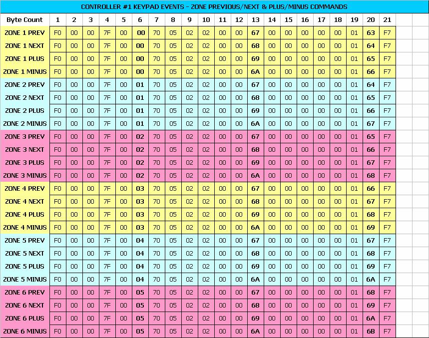
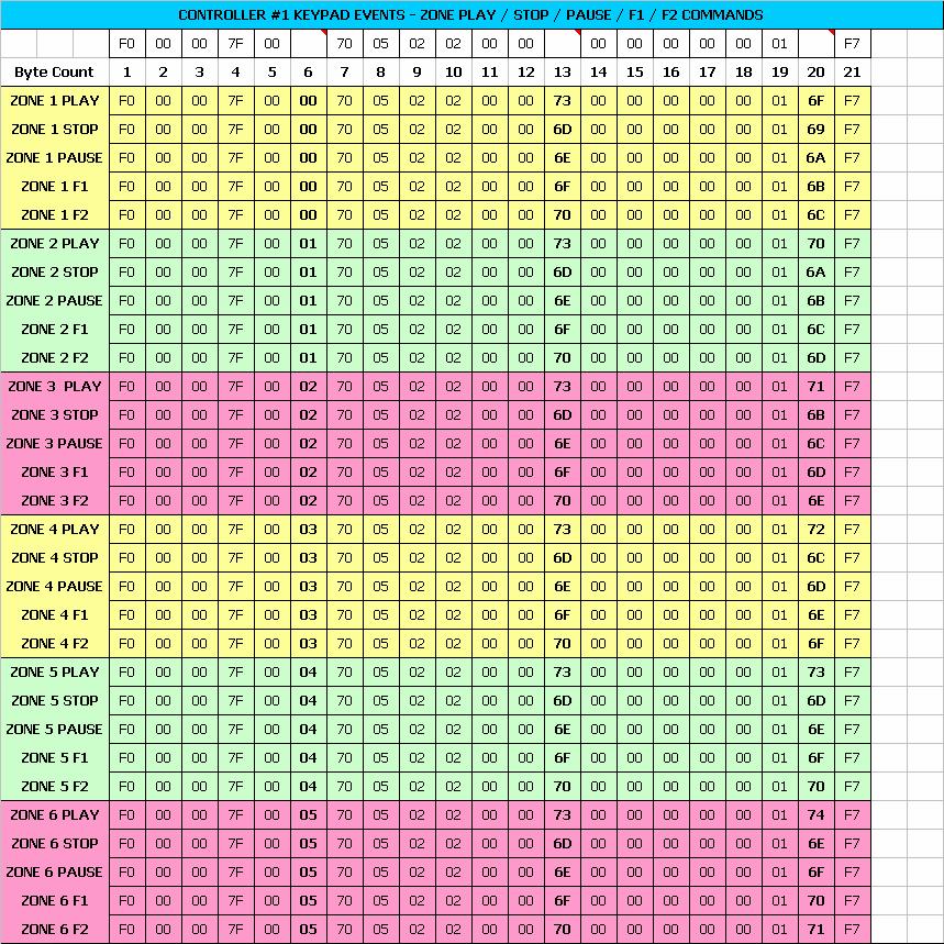
13 5 Buttons and Keycodes This section describes how to send various events associated with the Buttons found on the keypads and/or the IR remote The method for transmitting these button events falls into two categories: -Keypad Events: The Keypad Events are the events that the keypad is capable of sending. -Source Control Events: All others (Source Control Events) are only available via the IR Remote. Note: all values are in HEX. 5.1 Keypad Events Here is a list of UNO Keypad Event values and a description of which buttons they apply to: Value (Hex) Description 64 Setup Button 67 Previous 68 Next 69 Plus 6A Minus 6B Source (source toggle button) 6C Power 6D Stop 6E Pause 6F Favorite 1 70 Favorite 2 73 Play 7F Volume Up 80 Volume Down (because this value is > 7F, the special F1 character must be used) Here are some examples of some Keypad Events: Zone 1, Volume Up F F F B F7 Zone 2, Play F F F7 Zone 3, Favorite 1 F F F D F7 13
14 Here is a break out of the Zone1, Volume Up message (using above example of Keypad Event) Value Field Description F0 Start of Message 00 Target Controller ID Controller 1 00 Target Zone ID 7F Target Keypad ID The Controller itself 00 Source Controller ID 00 Source Zone ID Zone affected 70 Source Keypad ID Arbitrary Keypad ID (not otherwise used by the system 05 Message Type Event Message 02 Target Path, Num Levels 02 Target Path, Level 1 Root Menu 00 Target Path, Level 2 Run Menu 00 Source Path, Num Levels No Source Path is used 7F Event ID Lo Byte Volume Up 00 Event ID Hi Byte 00 Event Timestamp Lo Byte unused 00 Event Timestamp Hi Byte unused 00 Event Data Lo Byte unused 00 Event Data Hi Byte unused 01 Event Priority Low Priority (does not generate a handshake) 7B Checksum Recalculate when a preceding byte value is changed F7 End of Message 5.2 Source Control Events Source Control Events are unique to the System Remote and are all sent using the special Remote Control Key Event type with the actual Keycode passed in as the Data for the Event. Here is a list of the Source Control Events (Keycodes): Value (Hex) Description 01 1 Button 02 2 Button 03 3 Button 04 4 Button 14
15 05 5 Button 06 6 Button 07 7 Button 08 8 Button 09 9 Button 0A 0 Button 0B Volume Up 0C Volume Down 0D Mute (for zone, not source) 0E Channel Up 0F Channel Down 10 Power 11 Enter 12 Previous Channel 13 TV/Video 14 TV/VCR 15 A/B 16 TV/DVD 17 TV/LD 18 Input 19 TV/DSS 1A Play 1B Stop 1C Search Forward 1D Search Rewind 1E Pause 1F Record 20 Menu 21 Menu Up 22 Menu Down 23 Menu Left 24 Menu Right 25 Select 26 Exit 27 Display 28 Guide 29 Page Up 2A Page Down 15
16 2B Disk 2C Plus 10 2D Open/Close 2E Random 2F Track Forward 30 Track Reverse 31 Surround On/Off 32 Surround Mode 33 Surround Up 34 Surround Down 35 PIP 36 PIP Move 37 PIP Swap 38 Program 39 Sleep 3A On 3B Off 3C 11 3D 12 3E 13 3F Bright 43 Dim 44 Close 45 Open 46 Stop 2 47 AM/FM 48 Cue 49 Disk Up 4A Disk Down 4B Info 16
17 Here are some examples of some Source Control Events: Zone 1, Menu F F F E F7 Zone 2, Mute F F F D C F7 Zone 3, Record F F F F F7 Here is a break out of the Zone1, Menu message used in the above example: Value Field Description F0 Start of Message 00 Target Controller ID Controller 1 00 Target Zone ID 7F Target Keypad ID The Controller itself 00 Source Controller ID 00 Source Zone ID Zone affected 70 Source Keypad ID Arbitrary Keypad ID (not otherwise used by the system 05 Message Type Event Message 02 Target Path, Num Levels 02 Target Path, Level 1 Root Menu 00 Target Path, Level 2 Run Menu 00 Source Path, Num Levels No Source Path is used F1 Invert Invert the next byte 40 Event ID Lo Byte 40 = 0xBF inverted = Remote Control Key Release 00 Event ID Hi Byte 00 Event Timestamp Lo Byte unused 00 Event Timestamp Hi Byte unused 20 Event Data Lo Byte Menu (Keycode) 00 Event Data Hi Byte unused 01 Event Priority Low Priority (does not generate a handshake) 7B Checksum Recalculate when a preceding byte value is changed F7 End of Message 17
18 6 Using Request Messages The Request Data message is used to receive parameter data from the Controller. This may be used to receive Zone Power State, Volume Level, etc. When a Request Data message is sent to the Controller, a Set Data message is generated by the Controller and sent back to the Request Message sender. Since the Set Data message is of high priority, an Acknowledge message must be sent back to the Controller to acknowledge it received the Request message. Failure to send the Acknowledge message will result in a system delay of approximately 2.5 seconds. This is due to the Controller trying to re-send the Data. Data can be requested discretely for each zone parameter, or all of the Zone information can be requested in a single message. 18
19 7 Zones This section will provide information in regards to messages that only apply to Zone commands. This will include controlling the Zones as well as sending Request messages to Get the State of the Zones. Zero-based values are used for the Zone Numbers (i.e. 0 = 1, 1 = 2, and 2 = 3 etc ) 7.1 ON/OFF The simplest way to explicitly turn a Zone On or turn a Zone Off is by using the discrete Zone On/Off Event. The Event Data fields determine the Zone and On/Off state. This example shows using the Zone On/Off Event message to execute a Zone On command for Zone 1 of Controller 1. Refer to the Buttons section for information on toggling zone On/Off ( Power command found under Keypad Events) Set State Turn a specific Zone ON or OFF using a discrete message. Byte # Value F0 cc 00 7F F ## 00 zz xx F7 Byte #16 = 0x00 (off) or 0x01(on) Get State This is the Request message for the On/Off State of the selected Zone. Byte # Value F0 cc 00 7F zz xx F7 The return message would look like the following. Byte # Value F cc 00 7F zz ## xx F7 Byte #21 = 0x00 (off) or 0x01(on) Set All Zones On/Off State The RNET system can be sent a single message to issue an All On or All Off Event. The Controllers have the ability to enable or disable the All On/All Off state control per zone. See 19
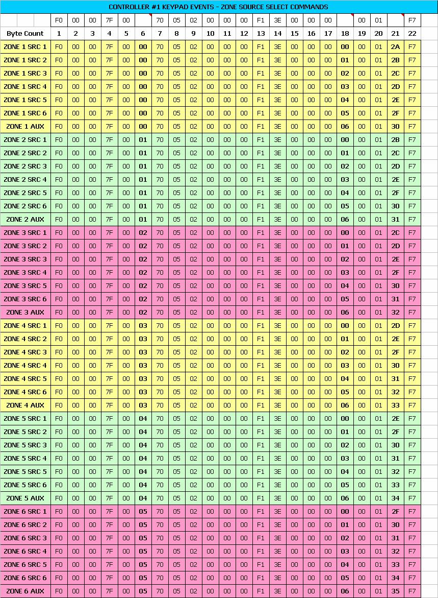
20 the Product Manual for instructions on programming each zone for System On Enable or System On Disable. Turn All Zones ON or OFF using a discrete message (all zones enabled in programming). Byte # Value F0 7E 00 7F F ## xx F7 Byte #17 = 0x00 (all off) or 0x01(all on) 7.2 Source Select The simplest way to explicitly select a Source per Zone is by using the discrete Source Select Event. The Event Data fields determine the Source being selected. Refer to the Buttons section for information on stepping through Sources ( Source Toggle command found under Keypad Events). Zero-based values are used for the Source Numbers (i.e. 0 = 1, 1 = 2, and 2 = 3 etc ) Set Source Select the Source for a particular zone using a discrete message. Byte # Value F0 cc 00 7F 00 zz F1 3E ## xx F7 Byte #18 = selected source number Get Source This is the Request message for what Source is selected on a particular Zone. Byte # Value F0 cc 00 7F zz xx F7 The return message would look like the following. Byte # Value F cc 00 7F zz ## xx F7 Byte #21 = source number -1 20
21 7.3 Volume Select The simplest way to explicitly select a Volume level per Zone is by using the discrete Volume Select Event. The Even Timestamp fields determine the Volume Level. The Event Data fields determine the Zone affected by the Volume being selected. Refer to the Buttons section for information on stepping through Volume levels ( Volume Up and Volume Down commands found under UNO Keypad Events). Volume levels displayed on UNO keypads range in value from in steps of 2 (i.e. 0, 2, 4, 6, etc ). These Volume levels are represented in Decimal when using RS-232 messages ranging in value from 0 50 (i.e. 0 = 0, 1 = 2, 2 = 4). In the actual Data message the HEX value is used which would range in value from 0x00 0x32. This means (0x00 = 0 = 0, 0x01 = 1 = 2, 0x02 = 2 = 4 0x32 = 50 = 100) Set Volume Select the Volume for a particular zone using a discrete message. Byte # Value F0 cc 00 7F F ## 00 zz xx F7 Byte #16 = volume level (0x00-0x32, 0x00 = 0 Displayed 0x32 = 100 Displayed) Get Volume This is the Request message for what Volume level is selected on a particular Zone. Byte # Value F0 cc 00 7F zz xx F7 The return message would look like the following. Byte # Value F cc 00 7F zz ## xx F7 Byte #21 = Volume Level -1 21
22 7.4 Bass Bass levels displayed on keypads range in value from -10 through +10. These Bess levels are represented in Decimal when using RS-232 messages ranging in value from In the actual Data message the HEX value is used which would range in value from 0x00 0x14. This means (0x00 = 0 = -10, 0x01 = 1 = -9, 0x02 = 2 = -8 0x14 = 20 = +10). NOTE: The keypad displays will not automatically update for this change Bass Up/Bass Down The following example shows the Bass level being increased or decreased. Value F0 cc 00 7F zz ## xx F7 Byte #16 = button event (Plus = 0x69 = Increase, Minus = 0x6A = Decrease) Set Bass Select the Bass level for a particular zone using a discrete message. Value F0 cc 00 7F zz ## xx F7 Byte #22 = Bass level (0x00 = -10 0x0A = Flat 0x14 = +10) Get Bass The current Bass setting for a particular zone can be obtained by using the following message. Byte # Value F0 cc 00 7F zz xx F7 The return message would look like the following. Value F cc 00 7F zz ## xx 7F Byte #22 = Bass level (0x00 = -10 0x0A = Flat 0x14 = +10) 22
23 7.5 Treble Treble levels displayed on keypads range in value from -10 through +10. These Treble levels are represented in Decimal when using RS-232 messages ranging in value from In the actual Data message the HEX value is used which would range in value from 0x00 0x14. This means (0x00 = 0 = -10, 0x01 = 1 = -9, 0x02 = 2 = -8 0x14 = 20 = +10). NOTE: The keypad displays will not automatically update for this change Treble Up/Treble Down The following example shows the Treble level being increased or decreased. Value F0 cc 00 7F zz ## xx F7 Byte #16 = button event (Plus = 0x69 = Increase, Minus = 0x6A = Decrease) Set Treble Select the Treble level for a particular zone using a discrete message. Value F0 cc 00 7F zz ## xx F7 Byte #22 = Treble level (0x00 = -10 0x0A = Flat 0x14 = +10) Get Treble The current Treble setting for a particular zone can be obtained by using the following message. Byte # Value F0 cc 00 7F zz xx F7 The return message would look like the following. Value F cc 00 7F zz ## xx F7 Byte #22 = Treble level (0x00 = -10 0x0A = Flat 0x14 = +10) 23
24 7.6 Loudness Loudness is displayed on keypads as On or Off. Loudness can be toggled On or Off with a Plus or Minus command. There can also be a discrete On or Off command selected. NOTE: The keypad displays will not automatically update for this change Loudness Toggle On/Off The following example shows how to toggle the Loudness On and Off for a particular Zone. Value F0 cc 00 7F zz ## xx F7 Byte #16 = button event (PLUS = 0x69 = On/Off toggle) or (MINUS = 0x6A = On/Off toggle) Set Loudness Turn Loudness On or Off for a particular zone using a discrete message. Value F0 cc 00 7F zz ## xx F7 Byte #22 = Loudness setting (0x00 = OFF, 0x01 = ON ) Get Loudness The current Loudness setting for a particular zone can be obtained by using the following message. Byte # Value F0 cc 00 7F zz xx F7 The return message would look like the following. Value F cc 00 7F zz ## xx F7 Byte #22 = Loudness setting (0x00 = OFF, 0x01 = ON ) 24
25 7.7 Balance Balance levels displayed on keypads range in value from Left 10 to Center to Right 10. These Balance levels are represented in Decimal when using RS-232 messages ranging in value from In the actual Data message the HEX value is used which would range in value from 0x00 0x14. This means (0x00 = 0 = Left 10 0x0A = 10 = Center 0x14 = 20 = Right 10). NOTE: The keypad displays will not automatically update for this change Balance Left or Balance Right The following example shows the Balance level being drawn More Left or More Right. Value F0 cc 00 7F zz ## xx F7 Byte #16 = button event (Plus = 0x69 = More Left, Minus = 0x6A = More Right) Set Balance Select the Balance level for a particular zone using a discrete message. Value F0 cc 00 7F zz ## xx F7 Byte #22 = Balance level (0x00 = More Left 0x0A = Center 0x14 = More Right) Get Balance The current Balance setting for a particular zone can be obtained using the following message. Byte # Value F0 cc 00 7F zz xx F7 The return message would look like the following. Value F cc 00 7F zz ## xx F7 Byte #22 = Balance level (0x00 = More Left 0x0A = Center 0x14 = More Right) 25
26 7.8 Turn On Volume Turn On Volume levels displayed on keypads range in value from in steps of 2 (i.e. 0, 2, 4 100). These Turn On Volume levels are represented in Decimal when using RS-232 messages ranging in value from In the actual Data message the HEX value is used which would range in value from 0x00 0x32. This means (0x00 = 0 = 0, 0x01 = 1 = 2, 0x02 = 2 = 4 0x32 = 50 = 100) NOTE: The keypad displays will not automatically update for this change Increase or Decrease Turn On Volume The following example shows the Turn On Volume level being increased or decreased. Value F0 cc 00 7F zz bb xx F Set Turn On Volume Select the Turn On Volume level for a particular zone using a discrete message. Value F0 cc 00 7F zz ## xx F7 Byte #22 = Turn On Volume level (0x00-0x32, 0x00 = 0 0x32 = 100) Get Turn On Volume The current Turn On Volume for a particular zone can be obtained using the following message. Byte # Value F0 cc 00 7F zz xx F7 The return message would look like the following. Value F cc 00 7F zz ## xx F7 Byte #22 = Turn On Volume level (0x00-0x32, 0x00 = 0 0x32 = 100) 26
27 7.9 Background Color Background Color is displayed on keypads as Amber, Green, or Off. The Background Color can be toggled through these selections with a Plus or Minus command. There can also be a discrete command selected for each choice. NOTE: The keypad displays WILL automatically update for this selection Background Color Off/Amber/Green toggle The following example shows how to toggle the Background Color for a particular Zone. Value F F zz ## xx F7 Byte #16 = button event (Plus = 0x69 = Off/Color toggle) or (Minus = 0x6A = Off/Color toggle) Set Background Color Select the Background Color for a particular zone using a discrete message. Value F F zz ## xx F7 Byte #22 = Background Color (0x00 = Off, 0x01 = Amber, 0x02 = Green) Get Background Color The current Background Color for a particular zone can be obtained using the following message. Byte # Value F0 cc 00 7F zz xx F7 The return message would look like the following. Value F cc 00 7F zz ## xx Byte #22 = Background Color (0x00 = Off, 0x01 = Amber, 0x02 = Green) F7 27
28 7.10 Do Not Disturb Do Not Disturb is displayed on keypads as On or Off. DND can be toggled On or Off with a Plus or Minus command. There can also be a discrete On or Off command selected Do Not Disturb On/Off Toggle The following example shows how to toggle Do Not Disturb On and Off for a particular Zone. Value F F zz ## xx F7 Byte #16 = button event (Plus = 0x69 = On/Off toggle) or (Minus = 0x6A = On/Off toggle) Set Do Not Disturb Turn DND On or Off for a particular zone using a discrete message. Value F F zz ## xx F7 Byte #22 = Do Not Disturb setting (0x00 = OFF, 0x01 = ON ) Get Do Not Disturb The current DND setting for a particular zone can be obtained by using the following message. Byte # Value F0 cc 00 7F zz xx F7 The return message would look like the following. Value F cc 00 7F zz ## xx F7 Byte #22 = Do Not Disturb setting (0x00 = OFF, 0x01 = ON ) 28
29 7.11 Party Mode Party Mode is displayed on keypads as On, Off, or Master. Party Mode can be toggled to On or Master with the Plus command. The Minus command will toggle Party Mode Off. There can also be a discrete On, Off, or Master command sent Party Mode On, Party Mode Master, and Party Mode Off NOTE: If Party Mode is Off, then Plus will issue a Master command. If a Zone is turned on while the rest of the system has Party Mode On and a different Zone is the Master, then Plus from a non-active Zone will issue an On command first and then a Master command second. If Party Mode is On and a different Zone is Master, then Plus from an active zone will issue a Master command. Minus will always issue an Off command. The following example shows how to toggle Party Mode for a particular Zone. Value F F zz ## xx F7 Byte #16 = button event (Plus = 0x69 = On/Off toggle) or (Minus = 0x6A = On/Off toggle) Set Party Mode Select Party Mode Master, On, or Off for a particular zone using a discrete message. Value F F zz ## xx F7 Byte #22 = Party Mode setting (0x00 = OFF, 0x01 = ON, 0x02 = Master) Get Party Mode The current Party Mode state for a particular zone can be obtained using the following message. Byte # Value F0 cc 00 7F zz xx F7 The return message would look like the following. Value F cc 00 7F zz ## xx F7 Byte #22 = Party Mode setting (0x00 = OFF, 0x01 = ON, 0x02 = Master) 29
30 7.12 Get All Zone info As stated previously, a message can be used to request all of a particular Zone's parameter values at once. This can be very useful for updating panel displays. The following is an example of how to request Zone information for a particular Zone and what the return message would look like Get State This is the Request message for the parameter values of the selected Zone. Byte # Value F0 cc 00 7F zz xx F7 The return message would look like the following. Byte # Value F cc 00 7F zz C 00 ## ## ## Byte # Value ## ## ## ## ## ## ## ## 00 xx F7 The parameter values are depicted in bytes These values will change depending on the state of the selected Zone. The above example shows the parameter values for a Zone configured and being used as follows: Byte #21 = Current Zone On/Off state (0x00 = OFF or 0x01 = ON) Byte #22 = Current Source selected -1 Byte #23 = Current Volume level (0x00-0x32, 0x00 = 0 Displayed 0x32 = 100 Displayed) Byte #24 = Current Bass level (0x00 = -10 0x0A = Flat 0x14 = +10) Byte #25 = Current Treble level (0x00 = -10 0x0A = Flat 0x14 = +10) Byte #26 = Current Loudness (0x00 = OFF, 0x01 = ON ) Byte #27 = Current Balance level (0x00 = More Left 0x0A = Center 0x14 = More Right) Byte #28 = Current System On state (0x00 = All Zones Off, 0x01 = Any Zone is On) Byte #29 = Current Shared Source (0x00 = Not Shared 0x01 = Shared with another Zone) Byte #30 = Current Party Mode state (0x00 = OFF, 0x01 = ON, 0x02 = Master)* Byte #31 = Current Do Not Disturb state (0x00 = OFF, 0x01 = ON )* *NOTE: Unsupported Features, information not available for CAS44 and CAA66 controllers 30
31 8 Displaying a String Since the keypad contains a text display, we ve provided a message that will allow you to send text messages to All Keypads simultaneously or a Specific Keypad individually. Alignment When sending a message to display text on a Keypad the first Data byte sets your Alignment (0x00 = Centered, 0x01 = Left justified). Flash Time Messages can be displayed constant or they can be flashed on the display for a brief time. When sending a message to display text on a Keypad the second and third Data bytes set the Flash Time. Flash Time defines how long the string is displayed. This is measured in 10ms increments with a value of 0x00 being constant. Null character A value of 0x00 used as a Data byte will be a text character of Null. A Null text character is always used after the last text character in the display string. With a 12 character text message you would use a Null character as the 13 th text character. A Null character is also used for each unused text character at the end of the text display message if the maximum number of Data bytes are not all used. 8.1 On All Keypads The following example shows how to display a text message on All Keypads (or other devices with a text display) in the system. Value F0 7F ## ## ## ## ## ## Byte # Value ## ## ## ## ## ## ## ## ## ## xx F7 cc = Controller Number -1 (0x7F = All Devices = All Keypads) zz = Zone Number -1 kk = Keypad Number -1 xx = Checksum Byte #19 = Alignment (0x00 = Centered, 0x01 = Left justified) Byte #20 = Low Byte of Flash Time Byte #21 = High Byte of Flash Time Byte #22 #34 = ASCII text characters (Section 11 ASCII Character Set) 8.2 On A Specific Keypad The following example shows how to display a text message on a Specific Keypad in the system. This is accomplished by setting the Target Device ID for the particular keypad in question. Value F0 cc zz kk ## ## ## ## ## ## Byte # Value ## ## ## ## ## ## ## ## ## ## xx F7 cc = Controller Number -1 zz = Zone Number -1 kk = Keypad Number -1 xx = Checksum 31
32
33 Byte #19 = Alignment (0x00 = Centered, 0x01 = Left justified) Byte #20 = Low Byte of Flash Time Byte #21 = High Byte of Flash Time Byte #22 #34 = ASCII text characters (Section 11 ASCII Character Set) 9 Display Messages The following section describes how to read Display Messages. These include Direct Display Feedback messages, Source Broadcast Display Feedback messages, and Multi-Field Broadcast Display Feedback messages. NOTE: In order to fully support the display capabilities, Direct Display feedback messages, Source Broadcast Feedback messages and Multi-Field Broadcast Messages, should be supported. (Multi-Field Broadcast messages are only used with XM.) 9.1 Reading Direct Display Feedback This section describes how to read Direct Display Feedback Messages. These Feedback messages are usually sent in direct response to a received command (e.g., If the current frequency of a Russound tuner is MHz FM, sending the Frequency Up command will trigger the Tuner to send a Display message back to the sender to update the frequency Display to "102.9 MHz FM"). The Direct Display Feedback message is sent directly to the Target Device ID of the message sender. The message can be displayed for a constant amount of time, or a "Flash" display with a specified length of time (Flash Time is in increments of 10ms). NOTE: It is possible that some display messages will include the special "Invert" control character (0xF1). NOTE: Some of the other bytes within this message may vary. Only the ones necessary to interpret the message are highlighted. NOTE: This message shows a text payload of 16 characters. Some devices may have a text payload of 12 characters. This is what the Direct Display Feedback message would look like using the above example. Value F D Byte # Value E D 48 7A D F F7 Byte #2 #4 = Target Device ID (This message should be displayed if the target Device ID matches the Device ID of your device.) Byte #19 = Overall Payload Size Byte #22 = Flash Time low byte (Flash time is in 10ms increments, 0x00 = Constant) Byte #23 = Flash Time high byte Byte #24 #40 = Text ( MHz FM used in above example) Byte #41 = Calculated Checksum 33
34 9.2 Reading Source Broadcast Display Feedback This section describes how to read Source Broadcast Display Feedback messages. These Feedback messages are sent to update all devices monitoring a given Source s status. These messages may be sent as a direct result of a sent command or as a general update. The Display Feedback message is sent with the source number of the Source attached. The attached source number indicates which Source the update is intended. The message can be displayed for a constant amount of time, or a "Flash" display with a specified length of time (Flash Time is in increments of 10ms). NOTE: It is possible that some display messages will include the special "Invert" control character (0xF1). NOTE: Some of the other bytes within this message may vary. Only the ones necessary to interpret the message are highlighted. NOTE: This message shows a text payload of 16 characters. Some devices may have a text payload of 12 characters. This example shows a Source Broadcast Display Feedback message with text "102.9 MHz FM". Value F0 7D D Byte # Value E D 48 7A D F7 Byte #4 = Target Keypad ID (NOTE: A value of 0x79 in the Target Keypad ID field indicates that this message is a Source Broadcast Display Feedback message.) Byte #19 = Overall Payload Size Byte #21 = Message type and Source Number = (0x10 (Source Broadcast Display Type) bit-wise OR-ed with the source number (e.g. source 1 = 0x10, source 3 = 0x12)) Byte #22 = Flash Time low byte (Flash time is in 10ms increments, 0x00 = Constant) Byte #23 = Flash Time high byte Bytes #24 #40 = Text ("102.9 MHz FM") Byte #41 = Calculated Checksum 34
35 9.3 Reading Multi-Field Broadcast Display Feedback Messages Multi-Field Broadcast Display Feedback messages are sent to update all devices monitoring the Source s status. These Feedback messages are sent to update all devices monitoring a given Source s status. These messages may be sent as a direct result of a sent command or as a general update. The Display Feedback message is sent with the source number of the Source attached. A Field ID is included with the message to indicate which item is being updated (see table below). The message can be displayed for a constant amount of time, or a "Flash" display with a specified length of time (Flash Time is in increments of 10ms). This example shows a Multi-Field Broadcast Display Feedback message text "49: Fine Tuning". Byte # Value F0 7D D C 34 Byte # Value 39 3A E E 69 6E F 7 Byte #4 = Target Keypad ID (NOTE: A value of 0x79 in the Target Keypad ID field indicates that this message is a Source Broadcast Display Feedback message.) Byte #19 = Overall Payload Size Byte #21 = Message type and Source Number = (0x20 (Multi-Field Display Type) bit-wise ORed with the source number (e.g., source 1 = 0x20, source 3 = 0x22.)) Byte #22 = Field ID bit and Flash Bit = (bits 0 6 = Field Id (i.e., 0x07 = 7 = Channel Name), Bit 7 Ignore. Invert control character (0xF1) will be inserted before this byte if Bit 7 is set. Bytes #24 #40 = Text ( 49: Fine Tuning ) Byte #41 = Calculated Checksum 10 Using the Acknowledge Message (Handshaking) When the controller sends a Return message in response to a Request message, the sender of the Request message must send an Acknowledge message in response to the Return message. Failure to send the Acknowledge message will result in a system delay of approximately 2.5 seconds while the controller tries to re-send the data. The controller will also send an Acknowledge message in response to a Set Data message that it is sent. It is not necessary to process the incoming Acknowledge message from the controller. NOTE: A Peripheral Source does not require Handshaking when the keypad ID used to send data is 0x70. If using a keypad ID of 0x70, and therefore no Handshaking, it is best to leave approximately 100ms between messages to ensure that all messages are processed correctly. If Handshaking is desired, it is recommended to use a keypad ID of 0x60. In this case, the Peripheral Source will send an Acknowledge message in response to any high priority event messages sent. Acknowledge messages can be (and normally are) used to trigger the release of any additional messages that may be in the sender's queue. This example shows sending a Frequency Up (Tune Up) event to a Russound Tuner: In this case the event priority byte is set to 0x00 (high) and the sender Keypad ID is 0x60. This means that the Internal Tuner will send an Acknowledge message in response. 35
36 Byte # Value F0 00 7D F C F7 Byte #4 = Source Number - 1 (Zero-based) Byte #7 = Sender Keypad ID - 0x60 (0x60 indicates that this message requires a handshake message if the event is high priority) Byte #15 = Event ID (TUNE UP) Byte #17 = Return Keypad Id - 0x70 (This is the keypad ID that the ST2 will send any resulting direct display message to. If this byte is set to 0x70, it will not require you to send a handshake message in response to the display message. If the original Sender keypad ID of 0x60 is used here, you will need to send a handshake message when the direct display message comes back. Failure to send the handshake message will result in a system delay of approximately 2.5 seconds, while the ST2 tries to re-send the data. It is recommended to leave this byte as 0x70.) Byte #19 = Source Number - 1 (Zero-based) Byte #21 = Event Priority (0 = high, 1 = low) Byte #22 = Calculated Checksum Handshake message returned to sender to acknowledge a high priority event message Byte # Value F D E F7 Byte #7 = Source Number of Event Recipient - 1 (Zero-based) Byte #8 = Message Type (HANDSHAKE) Byte #9 = Handshake Type (EVENT HANDSHAKE) Byte #10 = Calculated Checksum 36


37 11 ASCII Character Set to HEX Conversion Chart 37

38 12 Russound Controllers RS-232 Hex Code Listing 38
39 39
40 40
41 41
Russound Dual Tuners (ST2, ST2-XM, ST2-XM2, and ST2S)
") Russound Dual Tuners (ST2, ST2-XM, ST2-XM2, and ST2S) RNET Protocol & Specifications RS-232 Communication Document version 1.00.00 NOTE: This document is intended for ST2 Chassis Firmware Version 2.00.06
Russound Dual Tuners (ST2, ST2-XM, ST2-XM2, and ST2S) RNET Protocol & Specifications RS-232 Communication Document version 1.00.00 NOTE: This document is intended for ST2 Chassis Firmware Version 2.00.06
Application Note BDLxxxx RS232 SERIAL INTERFACE COMMUNICATION PROTOCOL (SICP V1.82)
") Application Note BDLxxxx RS232 SERIAL INTERFACE COMMUNICATION PROTOCOL (SICP V1.82) Table of Contents 1. INTRODUCTION... 1 1.1 PURPOSE... 1 1.2 DEFINITIONS, ABBREVIATIONS AND ACRONYMS... 1 2. COMMAND PACKET
Application Note BDLxxxx RS232 SERIAL INTERFACE COMMUNICATION PROTOCOL (SICP V1.82) Table of Contents 1. INTRODUCTION... 1 1.1 PURPOSE... 1 1.2 DEFINITIONS, ABBREVIATIONS AND ACRONYMS... 1 2. COMMAND PACKET
Planar Simplicity Series
 Planar Simplicity Series RS232 PROTOCOL Document 020-1285-00 1. INTRODUCTION 1.1 Purpose The purpose of this document is to explain in detail the commands and steps that can be used to control a Planar
RS232 User Guide. Planar Simplicity Series 4K Displays SL4364K SL5564K SL6564K SL7564K SL8664K. Simplicity Series 4K Displays User Guide A
 RS232 User Guide Planar Simplicity Series 4K Displays SL4364K SL5564K SL6564K SL7564K SL8664K 020-1344-00A Page 1 Copyright March 2018 by Leyard Optoelectronics Co., Ltd. and Planar Systems, Inc. All rights
Custom Installation Notes: Serial programming interface and IR remote commands for Arcam T32 Tuner
 23425 Custom Installation Notes: Serial programming interface and IR remote commands for Arcam T32 Tuner Contents Introduction...3 Conventions...3 Serial Cable Specification...3 transfer format...3 Command
Communications Protocol
 28 Kaysal Court, Armonk, NY 10504 914.598.1647 Communications Protocol For the Mirage Audio System Data acquisition and control of Autonomic equipment is performed by home automation systems or personal
HDV100A3 Command Response Protocol
 HDV100A3 Command Response Protocol Documentation Number: HDV100A3-4115m International Headquarters B+B SmartWorx 707 Dayton Road -- P.O. Box 1040 -- Ottawa, IL 61350 USA Phone (815) 433-5100 -- General
GIGAVAC Contactors J1939 Protocol
 GIGAVAC Contactors J1939 Protocol Documentation Revision: 7 See the last page for different revisions change history and apply to the firmware revisions to each update. Product Models: GXCAN15/16, MXCAN15/16.
Custom Installation Notes: Serial programming interface for Arcam A/V processors & receivers
 Custom Installation Notes: Serial programming interface for Arcam A/V processors & receivers Models covered: AVP700, AVR250, AVR300, AVR350 Contents Applicability... 2 Controlling Arcam A/V processors
PCD-FDE1 Network Controller Installation Manual
 PCD-FDE1 Network Controller Installation Manual Product Overview Perkins Innovation PCD-FDE1 provides direct access and remote control of a Russound multiroom audio system from an Apple iphone, ipod touch,
APPLICATION NOTES. M1 Audio Control. Basic control of distributed audio Systems using the M1 Control
 PRODUCT APPLICATION NOTES M1 Audio Control Basic control of distributed audio Systems using the M1 Control COMPATIBLE AUDIO DISTRIBUTION CONTROLLERS Russound - CAM & CAV series only (RNET) Proficient -
AH66T Serial Query Commands
 November 24, 2010 AH66T Serial Query Commands PURPOSE This bulletin explains how to understand the serial response received when a query command is sent to the AH66T. Query Commands In addition to the
Analyzing the command string for switch to input #
 Marshall VSW-2200 Switcher Control Protocol Firmware Version: 3.3 Document edited 8-22-2016 (legacy command structures have been removed from this document) Serial Port (over USB) Setting: Baud rate :
RS 232 Interface. RS 232 is the Serial interface on the PC. Three major wires for the Serial interface: Transmit Pin 2 Receive Pin 3
 RS 232 Interface RS 232 is the Serial interface on the PC Three major wires for the Serial interface: Transmit Pin 2 Receive Pin 3 Note: SR510 switches pins 2,3 internally HP Func. Gen. Requires a null
FLAT WIDE DISPLAY FWD-50PX1. PROTOCOL MANUAL (USER CONTROL ONLY) 1st Edition
 1st Edition") FLAT WIDE DISPLAY PROTOCOL MANUAL (USER CONTROL ONLY) 1st Edition Table of Contents 1. Communication Parameter... 3 2. Pin Configuration... 3 3. Communication Data Format... 3 4. General Function... 5
FLAT WIDE DISPLAY PROTOCOL MANUAL (USER CONTROL ONLY) 1st Edition Table of Contents 1. Communication Parameter... 3 2. Pin Configuration... 3 3. Communication Data Format... 3 4. General Function... 5
SAINT2. System Analysis Interface Tool 2. Emulation User Guide. Version 2.5. May 27, Copyright Delphi Automotive Systems Corporation 2009, 2010
 SAINT2 System Analysis Interface Tool 2 Emulation User Guide Version 2.5 May 27, 2010 Copyright Delphi Automotive Systems Corporation 2009, 2010 Maintained by: SAINT2 Team Delphi www.saint2support.com
Specification. For. Serial Interface DN-T645/625
 Date 2002-08-30 1 page of 55 Specification For Serial Interface DN-T645/625 Denon, Ltd. Date 2002-08-30 2 page of 55 Histories Rev. Date Name Description 1.00 Aug., 30, 02 J.Watanabe Date 2002-08-30 3
PRE32 RS232 protocol v1.21 Tomas Andersson
 PRE32 RS232 protocol 2014-11-07 v1.21 Tomas Andersson Description This document describes the RS232 protocol used to control the PRE32 device. Command structure Commands are sent to the device using the
KRELL EVOLUTION 2 STATUS FEEDBACK DESCRIPTION
 KRELL EVOLUTION 2 STATUS FEEDBACK DESCRIPTION Version 1.0 Wednesday, April 18, 2007 OVERVIEW The Evolution 2 (Evo-2) can report back it s operational status via the RS232 port. The system reports it s
Serial Communications Protocol Definition. Project: SDP-3
 Serial Communications Protocol Definition Project: SDP-3 Author: Simon Jarvis Updated: January 17, 2002 JBL Synthesis Edit: Chris Neumann Major rev 0 Minor rev 3 Approvals: Engineering: Marketing: 1 of
Minimum Core Module Version: g! version 5.4, requires S1616A Firmware Document Revision Date:
 Manufacturer: ELAN Integration Note Model Number(s): System S1616A (Multi-Zone Control) Minimum Core Module Version: g! version 5.4, requires S1616A Firmware 2.0.2.2 Document Revision Date: 05-25-2017
The RS-485 user manual for B800 series communication
 The user manual of B800 Series Rs-485 The RS-485 user manual for B800 series RS-232 inbuilt inside the main board of B800 series frequency inverter, we can effect RS-485 through fitting board externally.
$GDSWLYH0LFUR6\VWHPV
 $GDSWLYH0LFUR6\VWHPV $/3+$,QGXVWULDO3URWRFRO Revision 3.2 9711-8814A Alpha Industrial Protocol-V3.2.doc Page 1 of 58 Table of Contents 1.0 Revision History... 6 2.0 Introduction... 7 3.0 Control-T and
Custom Installation Notes: Serial programming interface and IR remote commands for Arcam AVR390/550/850/AV860/SR250
 Custom Installation Notes: Serial programming interface and IR remote commands for Arcam AVR390/550/850/AV860/SR250 Contents Introduction...3 Set-up...3 Conventions...3 Command and response formats...3
Generic RS232 protocol
 Generic RS232 protocol Table of content 1 Introduction... 2 2 Description... 2 2.1 Hardware specification... 2 2.2 Communication Setting... 2 2.3 Command Message Reference... 3 3 Protocol 1 : with ID...
RS232G Protocol Version 2.6.2
 RS232G Protocol Version 2.6.2 The RS232G Protocol is standard ASCII based. The commands must include parameters (separated by commas) and terminated with a carrier return = ASCII 13. The commands
Custom Installation Notes: Serial programming interface and IR remote commands for Arcam Solo Movie 2.1 and 5.1
 Custom Installation Notes: Serial programming interface and IR remote commands for Arcam Solo Movie 2.1 and 5.1 MENU SOURCE INFO OK TAPE POWER VOLUME MENU SOURCE INFO OK TAPE POWER VOLUME Models covered:
RV-5/MV-5. Serial Protocol Definitions. Software Version: V4.0x. Document Revision: July 2007
 RV-5/MV-5 Serial Protocol Definitions Software Version: V4.0x Document Revision: July 2007 Lexicon and the Lexicon logo are registered trademarks of Harman International Industries. U.S. patent numbers
CSCI 2212: Intermediate Programming / C Chapter 15
 ... /34 CSCI 222: Intermediate Programming / C Chapter 5 Alice E. Fischer October 9 and 2, 25 ... 2/34 Outline Integer Representations Binary Integers Integer Types Bit Operations Applying Bit Operations
RS 232 PINOUTS. 1. We use RJ12 for all of our RS232 interfaces (Link-2-Modbus & Link-2-PC- Serial/RS232). The diagram below shows our pin out.
. The diagram below shows our pin out.") RS 232 PINOUTS 1. We use RJ12 for all of our RS232 interfaces (Link-2-Modbus & Link-2-PC- Serial/RS232). The diagram below shows our pin out. 2. A DB9 Female to RJ12 Female Serial/Terminal Modular Adaptor
RS 232 PINOUTS 1. We use RJ12 for all of our RS232 interfaces (Link-2-Modbus & Link-2-PC- Serial/RS232). The diagram below shows our pin out. 2. A DB9 Female to RJ12 Female Serial/Terminal Modular Adaptor
Serial Communications Protocol Definition. Project: Lexicon MC-12/MC-12B/MC-12 Room EQ
 Serial Communications Protocol Definition Project: Lexicon MC-12/MC-12B/MC-12 Room EQ Updated: July 13, 2005 Software Version 5.0 Protocol Version: Major rev 1 Minor rev 6 2005 Harman Specialty Group All
Mate Serial Communications Guide This guide is only relevant to Mate Code Revs. of 3.30 and greater
 Mate Serial Communications Guide This guide is only relevant to Mate Code Revs. of 3.30 and greater For additional information contact matedev@outbackpower.com Page 1 of 14 Revision History Revision 2.0:
Doug Fleenor Design, Inc. RS-232 to DMX512 Interface, 2 Generation. March 8, 2010 (Software V1.2)
") Doug Fleenor Design, Inc. nd RS-232 to DMX512 Interface, 2 Generation March 8, 2010 (Software V1.2) The second generation RS-232 to DMX512 interface has numerous features beyond the original device. The
Doug Fleenor Design, Inc. nd RS-232 to DMX512 Interface, 2 Generation March 8, 2010 (Software V1.2) The second generation RS-232 to DMX512 interface has numerous features beyond the original device. The
SC1602LC 16x2 Large Characters RS232 LCD Module. User s Manual. Large Viewing Area 99mm x 24mm. Large Character Size. 4.84mm x 9.66mm.
 Large Viewing Area 99mm x 24mm Large Character Size 4.84mm x 9.66mm Features 16x2 Large Characters LCD RS232 Interface Simple Serial Command Wide Range Voltage Operation ( 9-15V ) 8 User s Defined Characters
LDV Communications Specification
 LDV6x-0308m - 1/22 Models: LDV6S and LDV6U LDV Communications Specification 2/19/2002 Rev 0.1 Created document draft JDS 2/22/2002 Rev 0.11 Added instructions on the use of Broadcast Messages JDS 3/18/2002
Azur 540R v3 Serial Control Protocol V1.0
 Azur 540R v3 Serial Control Protocol V1.0 1.1 RS232 Protocol The protocol is accessed via the RS232 protocol, i.e. a PC s rear panel com port. Notes: 1) All data consists of ASCII bytes. 2) Settings for
1. Implemented CM11 protocol
 1. Implemented CM11 protocol 1.1. Housecodes and Device Codes. The housecodes and device codes range from A to P and 1 to 16 respectively although they do not follow a binary sequence. The encoding format
JMY504M User's Manual
 JMY504M User's Manual (Revision 3.42) Jinmuyu Electronics Co. LTD 2011/6/28 Please read this manual carefully before using. If any problem, please mail to: Jinmuyu@vip.sina.com Contents 1 Product introduction...
Custom Installation Notes: Serial programming interface and IR remote commands for Arcam UDP411 BD Player
 23425 Custom Installation Notes: Serial programming interface and IR remote commands for Arcam UDP411 BD Player POWER / STANDBY ULTRA HIGH PERFORMANCE 24-BIT DAC ULTRA 1 Contents Introduction...3 Conventions...3
Sartorius Comparator. Interface Description for the CC Model Series
 98647-000-53 Sartorius Comparator Interface Description for the CC Model Series Contents Page General Information 4 General Specifications 5 Data Output Formats 6 Data Input Formats 11 Synchronization
LCD03 - I2C/Serial LCD Technical Documentation
 LCD03 - I2C/Serial LCD Technical Documentation Pagina 1 di 5 Overview The I2C and serial display driver provides easy operation of a standard 20*4 LCD Text display. It requires only a 5v power supply and
Definition of PLR on the RS485-bus. Version 1.06
 Definition of PLR on the RS485-bus Version 1.06 Version 1.06 1/35 Contents 1 INTRODUCTION...4 1.1 MOTIVATION...4 1.2 SCOPE OF THE DOCUMENT...4 1.3 VALUES...4 2 ARCHITECTURAL OVERVIEW...5 2.1 BUS TOPOLOGY...5
QBridge. I2C, SPI, CAN Control Software User s Manual. Date: Rev 1.3
 QBridge I2C, SPI, CAN Control Software User s Manual Date: 9-10-2005 Rev 1.3 1. Introduction...1 1.1. What QBridge can do?... 1 1.2. Disclaimer... 1 1.3. Operational Format... 1 1.4. QBridge-V2... 1 2.
CLOCKAUDIO. MR88 Automatic Microphone Mixer RS232 Programming Version 4.2
 CLOCKAUDIO MR88 Automatic Microphone Mixer RS232 Programming Version 4.2 Clockaudio Limited, 9 Stratfield Park Elettra Avenue, WATERLOOVILLE Hampshire. UK Tel : +44 (0)2392 251193 Fax : +44 (0)2392 251201
Specification. for. Serial Interface DN-C635
 Date 2003-01-28 1 page of 39 Specification for Serial Interface DN-C635 Denon, Ltd. Date 2003-01-28 2 page of 39 Histories Rev. Date Name Description 1.0 Jan.,28, 03 J.Watanabe Date 2003-01-28 3 page of
Custom Installation Notes IP/Serial programming interface and IR remote control commands for the SA10/SA20 integrated amplifier
 Custom Installation Notes IP/Serial programming interface and IR remote control commands for the SA10/SA20 integrated amplifier INTEGRATED AMPLIFIER PHONES AUX MUTE AUX PHONO STB PVR AV BD CD SAT POWER
RV-8 Serial Protocol Definition Software Version 2.0 Protocol Version:
 RV-8 Serial Protocol Definition Software Version 2.0 Protocol Version: Major Rev 1 Minor Rev 8 Manufactured under license from Dolby Laboratories. "Dolby," "Pro Logic," and the double-d symbol are trademarks
Application Note: Using Modbus With the Conext CL Series. Important Safety Instructions
 : Using Modbus With the Conext CL Series 976-0317-01-01 Rev A Important Safety Instructions READ AND SAVE THESE INSTRUCTIONS - DO NOT DISCARD This document contains important safety instructions that must
ambient XC RS232 Control Command Specification
 ambient XC RS232 Control Command Specification Table of Contents ambient XC RS232 Control Command Specification...1 Goal...2 COM port properties...2 Initialisation of RS232 communication...2 Determine
Sequential Event Recorder
 DESCRIPTION Sequential Event Recorder Product Specifications and Installation Data The Sequential Event Recorder (SER) is an intelligent Genius I/0 block that resides directly on the Genius LAN. The primary
Custom Installation Notes: Serial programming interface and IR remote commands for Arcam BDP100/300 BD Players
 23425 Custom Installation Notes: Serial programming interface and IR remote commands for Arcam BDP100/300 BD Players POWER / STANDBY ULTRA HIGH PERFORMANCE 24-BIT DAC 1 Contents Introduction...3 Conventions...3
Gateway Ascii Command Protocol
 Gateway Ascii Command Protocol Table Of Contents Introduction....2 Ascii Commands.....3 Messages Received From The Gateway....3 Button Down Message.....3 Button Up Message....3 Button Maintain Message....4
LCD03 - I2C/Serial LCD Technical Documentation
 LCD03 - I2C/Serial LCD Technical Documentation 2YHUYLHZ The I2C and serial display driver provides easy operation of a standard 20*4 LCD Text display. It requires only a 5v power supply and the two data
DataVU 5 - Interface Manual Modbus
 DataVU 5 - Interface Manual Modbus 59482 Contents 1 Introduction 5 1.1 Preface... 5 1.2 Typographical conventions... 6 1.2.1 Warning signs... 6 1.2.2 Note signs... 6 1.2.3 Representation modes... 6 2
Micro Module Shutter. Micro Module Shutter
 Developer Notes Micro Module Shutter Micro Module Shutter (XXXXX - Dev 0x01 / Sub 0xXX) Version 001 June 28, 2012 Revision History Rev Date Comments 001 6/28/12 Initial Release Table of Contents Firmware
How to write a SECA CAM by JF Version 1.00 April 2003
 How to write a SECA CAM by JF Version 1.00 April 2003 Page 1 of 14 Table of contents 1) Starting (Reading the smartcard)...3 1.1) ATR (Answer To Reset)... 3 1.2) Providers in the smartcard... 3 1.3) Smart
SPM723 Programmable Stereo Preamp/Mixer
 SPM723 Programmable Stereo Preamp/Mixer RS-232 Control Manual Released: 14 Aug 2001 Biamp Systems, 10074 S.W. Arctic Drive, Beaverton, Oregon 97005 U.S.A. (503) 641-7287 an affiliate of Rauland-Borg Corp.
DataVU 5 - Interface Manual Modbus
 DataVU 5 - Interface Manual Modbus 59482 Contents 1 Introduction 5 1.1 Preface... 5 1.2 Typographical conventions... 6 1.2.1 Warning signs... 6 1.2.2 Note signs... 6 1.2.3 Representation modes... 6 2
ED1021 I/O Expander with UART interface & analog inputs
 Preliminary Highlights 4.5V 5.5V power supply range. 12 GPIOs. Up to 40mA maximum current in each output except GPIO8 (up to a total device current of 175mA). Most GPIOs can be an input to a 10bit ADC.
Venstar Thermostat Adapter
 Developer Venstar Thermostat Adapter v001 Developer Venstar Thermostat Adapter Version 001 May 23, 2013 Revision History Rev Date Comments 001 05/23/13 Initial Release Page 1 of 13 Table of Contents 1
Azur 651R/751R Serial Control Protocol V1.01
 Azur 651R/751R Serial Control Protocol V1.01 1.1 RS232 Protocol The protocol is accessed via COM1 i.e. the rear panel RS232C port. Header Notes: Footer Group Data 1) All data consists of ASCII bytes. #
C1098 JPEG Module User Manual
 C1098 JPEG Module User Manual General Description C1098 is VGA camera module performs as a JPEG compressed still camera that can be attached to a wireless or PDA host. Users can send out a snapshot command
Blaupunkt ( DMS?? ) Page 1 of 13
 Page 1 of 13") Page 1 of 13 Blaupunkt ( DMS?? ) for controlling a Blaupunkt car radio. It is basically a 2 wire (rx/tx) async. serial protocol with 9 bits of data where the 8th bit is used for synchronisation. That made
Page 1 of 13 Blaupunkt ( DMS?? ) for controlling a Blaupunkt car radio. It is basically a 2 wire (rx/tx) async. serial protocol with 9 bits of data where the 8th bit is used for synchronisation. That made
RD-44 Audio Network Control Panel
 RD-44 Audio Network Control Panel Introduction: The RD-44 is designed to control the audio functions and sources of the MRD-70 marine radio and the MZ-100 DSP Zone Amplifier. With versatile mounting options,
PowerLogic ION6200 Serial Communications Protocol and ION / Modbus Register Map
 70022-05-XX PROTOCOL DOCUMENT 04/2007 PowerLogic ION6200 Serial Communications Protocol and ION / Modbus Register Map This document explains the Modbus protocol on the ION6200 meter. The ION6200 meter
Serial Communications Protocol Definition. Project: MC-12/MC-12B
 Serial Communications Protocol Definition Project: MC-12/MC-12B Updated: November 6, 2001 Major rev 1 Minor rev 1 Lexicon, Inc. 3 Oak Park Bedford, MA 01730-1441 (781) 280-0300 2001 Lexicon, Inc. All rights
Developer Notes for KeypadLinc Line
 Developer Notes for KeypadLinc Line Version 003 April 16, 2013 Revision History Rev Date Comments 001 1/11/13 Initial Release 002 1/22/13 Update s 003 4/16/13 Updated s Table of Contents 1 SUPPORTED DEVICES...
B l e n d i n g H i g h F idelity a n d A r c h i t e c t u r e ZR-4 4-SOURCE, 4-ZONE MULTIZONE RECEIVER KIT WITH AM/FM TUNER.
 B l e n d i n g H i g h F idelity a n d A r c h i t e c t u r e ZR-4 4-SOURCE, 4-ZONE MULTIZONE RECEIVER KIT WITH AM/FM TUNER user guide Congratulations! Thank you for purchasing the Niles ZR-4 MultiZone
MF1-RW-TTL-PCB Mhz Mifare ISO14443A reader/writer module with TTL interface CONTENT 1. MAIN FEATURES...,, PINNING INFORMATION...
 MF1-RW-TTL-PCB1 13.56Mhz Mifare ISO14443A reader/writer module with TTL interface RFID MODULE CONTENT 1. MAIN FEATURES......,,...2 2. PINNING INFORMATION........2 3. BAUD RATE SETTING.........3 4. COMMUNICATION
TORRIX RS485. Technical Documentation. with MODBUS Protocol. Edition: Version: 3 Art. no.:
 Technical Documentation TORRIX RS485 with MODBUS Protocol Edition: 2017-03 Version: 3 Art. no.: 350187 FAFNIR GmbH Schnackenburgallee 149 c 22525 Hamburg Tel.: +49 / 40 / 39 82 07 0 Fax: +49 / 40 / 390
Azur 851A Serial Control Protocol V1.0
 Azur 851A Serial Control Protocol V1.0 1. History Based on Azur 840A (V1 & V2) and 840E Serial Control Protocol V1.1. 2. RS232 Protocol The protocol is accessed via COM1 i.e. the rear panel RS232C port.
USB-ASC232. ASCII RS-232 Controlled USB Keyboard and Mouse Cable. User Manual
 USB-ASC232 ASCII RS-232 Controlled USB Keyboard and Mouse Cable User Manual Thank you for purchasing the model USB-ASC232 Cable HAGSTROM ELECTRONICS, INC. is pleased that you have selected this product
User Manual TAP CURIOUS
 User Manual TAP CURIOUS DO0281R00 7/18/2017 Table of Contents KUNBUS GmbH Table of Contents 1 Working safely... 3 2 Scope of delivery... 4 3 Introduction... 5 4 Overview... 6 4.1 Power supply... 8 4.2
Custom Installation Notes: Serial programming interface and IR remote commands for Arcam D33 DAC
 23425 Custom Installation Notes: Serial programming interface and IR remote commands for Arcam D33 DAC ULTRA HIGH PRECISION DIGITAL TO ANALOGUE CONVERTER D33 44.1 48 88.2 1 2 96 176.4 192 1 OPTICAL 2 1
Epson PX4 info page. Pinouts and circuit diagrams: RS232 Serial Port Parallel Printer Port Config DIP Switches System Bus Port
 Epson PX4 info page Epson PX4 info page Pinouts and circuit diagrams: RS232 Serial Port Parallel Printer Port Config DIP Switches System Bus Port Also i have summarised the PX4 manual with this CP/M command
B Interface description 12.01/
 B 95.3530.2 Interface description 12.01/00340396 Contents 1 Introduction 1.1 Preface... 3 1.2 Typographical conventions... 4 1.2.1 Warning signs... 4 1.2.2 Note signs... 4 1.2.3 Presentation... 4 2 Protocol
Chapter 2 Number System
 Chapter 2 Number System Embedded Systems with ARM Cortext-M Updated: Tuesday, January 16, 2018 What you should know.. Before coming to this class Decimal Binary Octal Hex 0 0000 00 0x0 1 0001 01 0x1 2
Winford Engineering ETH32 Protocol Reference
 Winford Engineering ETH32 Protocol Reference Table of Contents 1 1 Overview 1 Connection 1 General Structure 2 Communications Summary 2 Port Numbers 4 No-reply Commands 4 Set Port Value 4 Set Port Direction
RS-232 Control of the Advantage EQ281/8, EQ282/8 and Advantage SMS200
 RS-232 Control of the Advantage EQ281/8, EQ282/8 and Advantage SMS200 Biamp Systems, 14130 N.W. Science Park, Portland, Oregon 97229 U.S.A. (503) 641-7287 an affiliate of Rauland-Borg Corp. Introduction
Audio Integration Note
 OneHome Management and Control Solutions Audio Integration Note Manufacturer: Elan Model Number(s): S8.6 OneHome Software ver. 4.0 rel 1288 or later S8.6 Firmware compatible with HomeLogic 1.0.2.1 1.0.4.1
Audio Integration Note
 ELAN Home Systems Life Just Got Better Audio Integration Note Manufacturer: Elan Model Number(s): System 12 Comments: Version 5.0 (g!) requires S12 FW 2.02.00.04 Document Revision Date: 8/17/2011 OVERVIEW
SwitchLinc 2-Wire Dimmer (RF Only) (2474DWH - Dev 0x01 / Sub 0x24)
 (2474DWH - Dev 0x01 / Sub 0x24)") Developer Notes SwitchLinc 2-Wire Dimmer v004 Developer Notes SwitchLinc 2-Wire Dimmer (RF Only) (2474DWH - Dev 0x01 / Sub 0x24) Version 003 April 23, 2012 Revision History Rev Date Comments 001 1/27/12
Developer Notes SwitchLinc 2-Wire Dimmer v004 Developer Notes SwitchLinc 2-Wire Dimmer (RF Only) (2474DWH - Dev 0x01 / Sub 0x24) Version 003 April 23, 2012 Revision History Rev Date Comments 001 1/27/12
Card Dispensing/Collecting Machine
 A 1 OF 36 2010. 03. 02. Card Dispensing/Collecting Machine Series. 3,,. http://www.securetech-corp.com E-mail : sales@securetech-corp.com A 2 OF 36 2010. 03. 02. REVISION HISTORY No DATE DESCRIPTION REV
Matrix Switching System User Manual. Matrix Routing Switch. HDMI 4x4 HX-44 V.2012HX44.00
 User Manual Matrix Routing Switch HDMI 4x4 HX-44 V.2012HX44.00 Copyright and Trademarks: All rights reserved by ZIGEN INC. No part of this document may be reproduced in any form or by any means without
Specification E2 Interface
 Specification E2 Interface Version 4.1 Name Date Created: Robert Mayr. 15.04.2011 Checked: Haider A. 15.04.2011 Approved: Reason for change: Text corrections TABLE OF CONTENTS 1 INTRODUCTION... 3 1.1 Overview..................................................................................................................
INSTEON Hidden Door Sensor
 Developer Notes INSTEON Door Sensor Developer Notes INSTEON Hidden Door Sensor Version 005 October 18, 2013 Revision History Rev Date Comments 001 4/15/13 Initial Release 002 8/2/13 Updated s 003 9/6/13
MPX 1 V1.10. MIDI Implementation Details
 MPX 1 V1.10 MIDI Implementation Details 1998, Lexicon, Inc. All Rights Reserved Lexicon, Inc. 3 Oak Park Bedford MA 01730-1441 Tel: 781 280-0300 Fax: 781 280-0490 Lexicon Part No. 070-11835 Rev 1 Printed
CODA Online Data Formats
 CODA Online Data Formats Evio Header Formats Bank : 32 bits MSB (31) LSB (0) Length (32 bit words, exclusive) Tag (16 bits) (2) Type (6) Num (8) Segment : Padding Tag (8 bits) (2) Type (6) Length (16)
Serial Communication Control Interface User s Manual
 User s Manual Edition 1.0, September 2015 www.moxa.com/product For the following products: MD-219 Series MD-224 Series MD-226 Series MPC-2190 Series MPC-2197 Series MPC-2240 Series MPC-2247 Series MPC-2260
RS232-ADC16/24 Manual
 RS232-ADC16/24 Manual Version 1.11 Copyright taskit GmbH 2009 www.taskit.de Page 1/22 Table of contents 1 Features...3 2 Introduction...3 3 Bringing into service...4 4 Application Sample...5 5 Frame layout...6
Technical Specification. Third Party Control Protocol. AV Revolution
 Technical Specification Third Party Control Protocol AV Revolution Document AM-TS-120308 Version 1.0 Page 1 of 31 DOCUMENT DETAILS Document Title: Technical Specification, Third Party Control Protocol,
OmniPro II Version 2.14 Firmware Release
 OmniPro II Version 2.14 Firmware Release ADD THIS DOCUMENT TO YOUR OMNIPRO II OWNER S MANUAL Description The OmniPro II Version 2.14 firmware adds the following new features: Support for Z-Wave technology
Ultrabeam RCU-06 USB port description
 Abstract The Ultrabeam RCU-06 is an electronic controller used in a variety of Ultrabeam antennas. The main task of the controller is to tune the antenna by moving the (radiating) elements, based on the
dcs Remote Control Codes User Manual
 February 2016 Data Conversion Systems Ltd. 2009-2015 All rights reserved. No part of this publication may be reproduced, stored in or introduced into a retrieval system, or transmitted in any form, or
LCD05 datasheet 1.0
 LCD05 green displays LCD05 blue displays The I2C and serial display driver provides easy operation of a standard 20 x 4 or 16 x 2 LCD Text display. It requires only a 5v power supply and the two data connections
DEBUGGING SERIAL COMMUNICATIONS WITH OTHER DEVICES
 DEBUGGING SERIAL COMMUNICATIONS WITH OTHER DEVICES NOTE: This application note is intended for users connecting an external device to a HomeVision serial port. It may be helpful to users connecting to
MIDI CPU Firmware V User Manual
 MIDI CPU Firmware V..2 MIDI CPU Firmware Version.2 User Manual Updated 23-5-3 Additional documentation available at: http://highlyliquid.com/support/ 23 Sonarcana LLC Page / 55 MIDI CPU Firmware V..2 Table
USB-SD MP3 Module Manual
 USB-SD MP3 Module Manual WT9501M03 www.elechouse.com Copyright reserved by elechouse Features www.elechouse.com Can play 8 ~ 320Kbps MP3 audio files; Support maximum capacity of 32G Byte SD card; Support
The Traceroute Command in MPLS
 The Traceroute Command in MPLS Document ID: 26585 Contents Introduction Prerequisites Requirements Components Used Conventions Normal traceroute Command MPLS traceroute Command no mpls ip propagate ttl
RFID MODULE Mifare Reader / Writer SL030 User Manual Version 2.4 Nov 2011 StrongLink
 RFID MODULE Mifare Reader / Writer User Manual Version 2.4 Nov 2011 StrongLink CONTENT 1. MAIN FEATURES... 3 2. PINNING INFORMATION... 4 3. DEVICE OPERATION... 5 3-1. Clock and Data Transitions:... 5 3-2.