The IC can be used in new installations or as a replacement for an existing sprinkler control system.
|
|
|
- Sherilyn Stokes
- 6 years ago
- Views:
Transcription


1
2 1 Introduction 1 Introduction The IrrigationCaddy IC-W1 (IC) is a WiFi enabled irrigation controller. The IC allows the user to control and schedule an irrigation system from any computer with a web browser. No special software or clients are required, just a Web Browser on a computer or internet enabled device. The IC can be used in new installations or as a replacement for an existing sprinkler control system. The IC supports up to 11 different irrigation zones on the main unit, and it can be expanded up to 43 irrigation zones by adding expansion modules (ICExpanders). If your system uses a master valve, one of the outputs will be used as the master valve control, thus allowing only a maximum of 10 zones if using only the main unit, and up to 42 if fully expanded. Out of the box the IC is configured with output #11 set as the master valve output, this can be changed, and the master valve control disabled by disabling the master valve control setting in the Settings -> Other section. 2

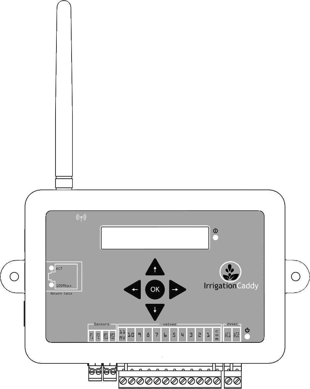
3 2 Mounting on the Wall 2 Mounting on the Wall 2.1 Steps: 1. Find an appropriate location for the IC, and hold the enclosure in place. 2. Using a pen make marks through the screw mounting holes (C) on the plastic ears protruding from the enclosure. 3. NOTE: If installing on Drywall make sure you use screw anchors 4. Put the device aside, and drill a hole on each one of the marks you made. 5. Put the IC back in place and insert the screws through the mounting holes. A. WiFi Antenna B. Expansion Port C. Mounting Ear D. Ethernet Port E. USB Port F. Flow Sensor Port G. Rain Sensor Port H. Valve wire connector 3
4 2 Mounting on the Wall I. Power Connector J. Power light indicator K. Activity Indicator L. LCD Screen 4
5 3 Connecting Valve Wires 3 Connecting Valve Wires 3.1 Steps: 1. If this is a replacement installation, first remove the old Sprinkler Control System, and attach the IC to the wall. Make sure the valve cables can reach the IC. 2. Identify the common cable and connect it to the com output. 3. Connect valves 1 through 10, to the corresponding outputs on the IC 4. If your installation includes a master valve, connect the master valve to output #11 ( 11 MV ). 5. Connect the power cable to the IC using the AC1 AC2 (I) outputs using the connector provided. 6. Plug the wall transformer to a power outlet. 7. The IC should now be installed, and ready to be configured. 5
6 4 Connecting to the Network 4 Connecting to the Network When you first apply power to the IC, the IC will boot up and broadcast a WiFi SSID called IrrigationCaddyAP. This SSID will allow you to gain access to the unit, and configure it so that you can connect it to your own WiFi network ( Router ). Follow the connection steps appropriate for your platform. 4.1 Windows 7 Connection Steps Steps: 1. Make sure the unit is plugged in. 2. Click on the network icon on the taskbar 3. Find the IrrigationCaddyAP network, open it, and click on Connect. If IrrigationCaddyAP does not show right away, wait a few seconds until it 6


7 4 Connecting to the Network shows up. You might have to repeat step 2 to refresh the networks 4.2 MAC OS X Connection Steps 1. Click on the Wireless Signal indicator on the top bar 7

8 4 Connecting to the Network 2. Find the IrrigationCaddyAP network, and select it. 8

 2.")
9 4 Connecting to the Network 4.3 Connect Caddy to your Router 1. Once you have connected to the SSID, open a web browser and navigate to (You might have to wait up to 30 seconds before you are able to access the page after connecting to IrrigationCaddyAP SSID. Refresh the page until it connects) 2. Now you are connected to the IrrigationCaddy SSID, however the objective should be to connect the IC to your own WiFi network SSID, so that you can access the IC like any other networked device you might own. 3. On the menu bar click on Setup and then Settings 9


10 4 Connecting to the Network 4. Open Network Settings, and click on the Scan Networks button. 5. When the scan finishes, it will display a list of available network SSIDs. Click on your preferred network SSID to connect to it. 6. If the network SSID is protected, you will be prompted to enter a passphrase. Enter the passphrase and click on Connect to Network. 10

. 2.")
11 4 Connecting to the Network 7. The IC will then display a reconnection message, and it will reboot. When the IC reboots it will try to reconnect to the new network SSID you just selected. Now you can reconnect your laptop/pc/portable device to the new network SSID so that you can access the IC in the new network (usually your home WiFi router). 2. To go back to the original network once again click on the network icon on the taskbar, and select your preferred network SSID, which in most cases it would be the same as the network SSID you selected for the IC. On Windows 7: 11

12 4 Connecting to the Network On MAC OS X: 12


13 4 Connecting to the Network 8. The IC would have rebooted, and the LCD display on it would now show a different IP address, which would have been obtained from the router you just connected it to by selecting its SSID. 9. Now you can open a Web Browser and put the IP address displayed on the ICs LCD display, in the address bar to start using the IC.(The IP shown above is an example, your IC will likely show a different IP) 13
14 5 Connecting Expansion Modules 5 Connecting Expansion Modules The IC-W1 zone capacity can be expanded to up to 43 zones by adding expansion modules (EXP-800). The expansion modules connect into the Expansion Port for the IC-W1. Up to 4 expansion modules can be used by adding an expansion module hub (H-500). 14
15 6 Usage Going to the web address will present you with a Web Interface to the IC.(NOTE: If the hostname does not work ("irrigationcaddy"), use the IP Address which is displayed on the LCD screen on the device) The IC is capable of scheduling irrigation times using five different programs, which can be scheduled independently. The IC also provides the user with a Run Now program, which allows the user to execute a one time schedule, immediately after programming. 6.1 Setting the Clock It is important that you set the IC's clock time to the current time Steps: 1. Click on Settings. 2. Click on Clocks. 15


16 3. Set the time: a. You can use the Sync Clocks" button to synch the IC s clock with your computer s clock. b. You can also manually set it by clicking on the field next to the Set Datetime button. c. It is also possible to set the time using NTP (Network Time Protocol). Click on the Use NTP Time checkbox to enable the NTP time feature. 16
17 NTP will try to connect to the NTP Server listed every few minutes, and update the local clock. A Timezone will also have to be specified. 4. Once the IC s clock has been set, this step does not have to be repeated. 6.2 Setting a Program s Schedule Turn the program ON or OFF Turn the program ON by checking the ON/OFF radio buttons at the top Selecting which days to run First select the program you would like to configure. 17


18 The IC supports several different programming schemes INDIVIDUAL DAYS With this scheme you set what days of the week you would like to run your sprinklers. The program will then start only on the days you selected. EVEN / ODD DAYS With this scheme you select whether you would like the system to run on only even numbered days (2, 4, 6 etc) or odd numbered days (1, 3, 5 etc). Then you would select the individual week days you would like the system to run on. This way you can tell the system to run on even days, but not on weekends for example. 18
.")


19 If you would like to run even or odd days regardless of what day of the week it is then you would select every day of the week. EVERY N DAYS With the Every N Days option you can tell the system to run exactly every specified number of days (i.e. every 3 days). As with the Even / Odd option, you can combine this option with the individual days, and also restrict which days of the week the system should run. For example you can tell the system to run every 2 days except for Mondays, and Wednesdays. You can use the "Days before next run" to move the starting day forward into the future, as opposed to the current day, which is the default if this setting is not used. The Even / Odd Days and Every N Days options cannot be combined. Once one is selected the other is disabled Start Times The IC provides up to 5 start times per program. The start times are used to run the same program at different times during the day. For example, in certain scenarios it makes sense to water the same areas twice a day, once early in the morning and once later in the day. 19


20 This can be accomplished by enabling one extra start from start times number 2, 3, 4 or 5. Start time 1 is always enabled, and it is the default start time. In other scenarios, where water runoff is a concern, the programs can be shortened, but more start times can be enabled thus maintaining the total amount of water output desired, while preventing runoff. To select the program s start time click on the text field below the Start Time heading, and a time picker will display. Then select the start time using the up and down controls Seasonal Adjust The Seasonal Adjust feature allows you to increase or decrease the watering time by a percentage of the schedule's total time. For example in winter you might want to decrease the amount of total watering being done, without changing the relative amounts that each zone receives, and without having to change each of the zone's assigned run times. In that case you can use the Seasonal Adjust slider to adjust the total run time Weather Adjust NOTE: For the Weather Adjust feature to work, the caddy must be connected to the Cloud, otherwise the caddy is not able to retrieve the weather data. The Weather Adjust feature allows the caddy to retrieve precipitation information from the Cloud. You can then tell the caddy how to use the precipitation data, and thus decrease the amount of watering that should be done. For example if it rained in the last 24 hours it is likely you would like the caddy not to water as much. In that case you can use the precipitation data being retrieved, and allow the caddy to water a lesser amount, if the precipitation is more than a certain value. For example "If it rained more than 0.53 inches in the last 24 hours, then only water 50% of the total time scheduled". 20


21 Enable / Disable Weather Adjust By default the Weather Adjust feature is disabled. In order to enable it you must switch the "Use Weather Adjust" option from "NO" to "YES". Once the "Use Weather Adjust" option is set to "YES", the area would expand to display the full set of controls. 21


22 6.2.6 Setting zone run times To set the zone run times, under the Run Times heading, move the slider to the right to increase the amount of time a zone should run. The run time will display on top of the slider. 1. Minimum time boundary 2. Maximum time boundary. The zone cannot be set to run for more than the high time boundary. This limit can be changed from the settings page. 3. The slider. 4. The amount of time the zone will run Using the Run Now Program The "Run Now" program allows you to run the system at the current moment. Just set the duration times on each one of the zones you are interested in running, and click on the Run Now button. This will start the system immediately. 22


23 6.3 Status Area The status area is divided into sections. 1. The first section indicates whether the system is ON or OFF, and it allows the user to turn the system ON or OFF. Turning the system OFF means that the scheduler will not run and therefore the programs will never execute. However the device will continue to answer to network requests as usual. 2. The next section indicates the run time remaining for a program and for the zone currently running within that program. It also allows the user to stop the running program or zone. 3. The next section is a global status area for the zones. Bright Green will display for a zone currently running, Muted Green / Brown is for a zone that will run in the future after the zones above it have finished running, and Red indicates the zone has already run, or the zone will not run at all. 23


24 4. The next section indicates the Cloud service connecton status. 5. The next section shows the rain totals. 24


25 6. The next section indicates the rain sensor status. 7. The next section indicates flow sensor status. 6.4 Calendar You can see a visual representation of when the programs will run by clicking on the "Calendar" link. 25


26 There are three possible calendar views, "month", "week", and "day". By default "month" will display but you can change the view by clicking on the appropriate button on the top right hand corner of the view. The following is an example "week" view, where you can clearly see Program 1 will run on Monday starting at 6am, Program 2 will run on Wednesday starting at 8am, and Program 3 will start on Thursday at 12pm. 6.5 Log If a USB Flash Drive has been inserted into the USB port, and you have a flow sensor connected, the unit will log its water usage to it. The data can then be displayed and plotted by clicking on the Log link. 26


27 The top section will allow for a date selection, so navigate through the log data. When the log is opened it defaults to the current day. The chart on the top will show the water usage per hour for the day selected. The hours are displayed from 0 to 23. The bottom chart displays the total water usage per day for the whole month. The Month is the month for the day you have selected. Clicking on the bar for the day, will change the chart on the top for the hours for each day, showing the water usage by hour. This way you can see the detail usage by hour for each day simply by clicking on the bar for the day of interest. 27


28 6.6 Settings The settings page can be accessed by clicking on the "Settings" link. Once you access the settings page the system settings are subdivided into sections. 28

29 6.6.1 Firmware Version This section displays the firmware version the system is currently configured with Clocks The section allows the user to set the system clock (see "Setting the Clock" under Usage). The clock will not sync if a program is running; the only exception to this rule is if NTP time is enabled; in which case the clock will change. 29

30 There are 3 different ways of adjusting the internal clock. The first is by syncing the computer time (the computer you are accessing the caddy from), with the internal clock. Clicking on the "Sync Clock" button will sync the computer time displayed above the button, with the internal clock time displayed below the button. The second way is manual. By clicking on text field pointed by the "Pick a Date / Time" label, a date time picker will display allowing you to select the date and time. After selecting the date and time you can click on the "Set Datetime" button, and the internal clock will be synced with the date and time selected. The last way is NTP (Network Time Protocol). NTP relies on an Internet connection, therefore if the IC cannot access the internet, this method will not work. NTP must access a server on the Internet in order to retrieve accurate time information. The IC will request time information from the server every 10 minutes. 30

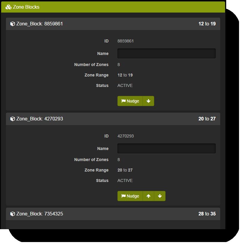
31 6.6.3 Network Settings The section displays the current network system settings and also allows for setting the hostname, DHCP or Static IP address configuration, IP Address (if static was chosen), port number, default gateway, and network mask. Unless you are proficient with network terms, and understand how devices communicate in an Ethernet network, it is recommended that you don t change the default settings Zone Blocks This section shows the connected expansion blocks if any. Each expansion block is identified by an ID, and an optional Name. Each block also indicates how many zones it has, and whether the block is active or inactive. Once a block is connected to the main unit, the block registers itself with the unit, and the main unit will remember it. If the expander is then disconnected the block will show as INACTIVE in this section. The Nudge button allows the user to identify the expander if more than one expander is connected to the main unit. The ACT led on the expander will flash red rapidly when nudged. 31
32 32

33 6.6.5 Zone Names This section allows for the setting of the zone names. By default the zones are numbered and the names are empty. By giving a zone a descriptive name it is easier to remember which zone waters what area Authentication In here you can enable or disable authentication. By default authentication is disabled. By turning authentication ON, and setting a username and password, the next time you try to access the device you will be prompted for a username and password. If the credentials you enter don t match the credentials you specified here, you will not be allowed access to the IC s interface. If you forget the username and password, the only way to access the IC is to reset it to its factory default settings by (See Resetting to Factory Defaults). 33


34 6.6.7 Cloud This section allows you to connect the caddy to the Cloud service. The section has a switch to enable or disable the cloud feature, as well as 2 separate fields for the "API Key" and the "Controller ID". Before the caddy can connect to the Cloud service, you must first create an account at "cloud.irrigationcaddy.com". Follow the directions there on how to link your caddy to the service. Once the account has been created and configured with a caddy in it, you will be able to obtain an API Key and a Controller ID that can be entered in these fields. Enter those values in the fields and enable the switch and save, and the caddy will then connect to the Cloud service Other This section is reserved for other unrelated settings. "Use Rain Sensor" is intended to be used with a rain sensor. When a rain sensor is plugged into the rain sensor connector, you can use this setting to tell the system whether it should pay attention to the sensor or not. If the "Use Rain Sensor" setting is checked the system will check for a rain sensor, and if a sensor is present, it will water or stop watering according to the sensor state. If the sensor is wet, the system will not water. 34
35 The "Run Now" program is excempt from the effects of this setting. The "Run Now" program will water even if the rain sensor is WET, and the "Use Rain Sensor" setting is enabled. "Check if Rain Sensor is Normally Open" is used to tell the IC that the rain sensor connected to the IC is a "Normally Open" type rain sensor. There are 2 types of rain sensors; "normally close" and "normally open". If the sensor attached is of the "normally close" type then leave this setting unchecked. "Use Flow Sensor" should be selected when a flow sensor is available and can be connected to the IC. "Units". If a flow sensor is in use, you can select the water usage is reported, in Liters or in Gallons. "Units per Pulse". The IC supports pulse based flow sensors. This settings tells the IC how to translate each pulse into units. Does each pulse mean 1 Gallon? Or 2? etc. "Flow Rate Average Period". See "Flow Meter Settings" on page 40 "Use #11 as Master Valve" provides for the ability to dedicate a zone as a "Master Valve". This means that if this setting is checked, every time a regular zone turns on, the #10 zone will also turn on. This zone can also be used to trigger a pump start relay. In systems where a water pump is used, a pump relay can be connected to zone #10 while this setting has been enabled. Every time a zone turns on due to the schedule, the pump relay would get triggered. The "Max Zone Run Time" setting is intended to globally limit the maximum amount of run time that a zone can be set at. The main purpose of the setting is to prevent programming mistakes and avoid unintended long periods of watering. 35
, and 1 OK button, used mainly for selecting options.")


36 6.7 Manual Control The IC can also be controlled from the front panel. The front panel has a keypad with 4 arrow keys (UP, DOWN, LEFT, RIGHT), and 1 OK button, used mainly for selecting options. The UP and DOWN arrows can be used to navigate the menu on the LCD. The menu is very simple, and not all functions are available from the front panel. The top level menu includes the following options: Network Info Run Zone Stop Zone Run Program Zone Status The UP and DOWN arrows can be used to move from one option to the next. The menu wraps around so if you press DOWN on the "Zone Status" option, the next option will be "Network Info"; Same the other way around, if you press UP while on the "Network Info" option the next option will be "Zone Status". By default, while nothing is happening the LCD display will show the current IP address. 36


37 6 Usage Pushing on the RIGHT button while on the IP address screen will display the MAC address screen. Pushing on the UP or DOWN buttons while on the IP address or MAC address screens will start the menu selection Network Info Pushing OK while pointing to the "Network Info" menu option goes back to the IP address screen Run Zone Pushing OK on the "Run Zone" menu option will allow you to run an individual zone. After pressing OK a new screen is shown where you can select the zone number to run and the amount of time to run it for. The time defaults to 15 minutes. While on the zone selection screen you can use the LEFT and RIGHT buttons to navigate from selecting the zone number, the hours and minutes. After selecting the zone number, hours and minutes you can press OK to start the zone. At this point the screen will change and display the "Zone Status" screen Stop Zone Pushing OK while on the "Stop Zone" menu option has the effect of stopping the currently running zone if any. If no zone is running nothing happens Run Program Pushing OK while on the "Run Program" menu optino allows you to run an already scheduled program. The LCD screen changes to the program selection screen where you can select the program number to run, from 1 to Zone Status The "Zone Status" menu option shows you the current run status for the system. If a zone is currently running it will display the zone number for the zone that is currently running as well as the remaining time. 37
38 The remaining time will tick downwards towards 0; at which point the zone will stop and the screen will go back to the "Network Info" screen. 38

39 7 Rain Sensor 7 Rain Sensor The IC supports most "normally close" or "normally open" rain sensors. The sensors could be wired or wireless. Pretty much any standard off the shelf rain sensor will work. 7.1 Connecting The IC has 1 rain sensor port with 2 outputs labeled RS1 and RS2. Also most rain sensors have 2 wires coming out of them. One of those wires goes into RS1 and the other into RS2. The outputs don't have a polarity so it does not matter which wire goes to which output. It is very important that the wires do NOT have a voltage in them. This can happen if the sensor wires are somehow connected to the common wire. It is a common practice for installers to do this, so specially if the IC is replacing an older controller, that you make sure the sensor is not energized, and not connected to the common wire. 39

40 8 Flow Meter 8 Flow Meter The IC has 1 port dedicated to a flow meter. If a Reed Switch type flow meter is attached to FS1, FS2 and if the flow meter port is enabled in the "Settings -> Other" section, the IC will track the water usage, and log it to a USB memory stick if one is attached to the USB port on the IC. 8.1 Flow Meters Supported The IC supports Reed Switch based flow meters. These type of meters look like a regular water meter, but they have a small appendage (the Reed Switch), on top of one of the dials. As the dial turns the Reed Switch "ticks", or turns the switch ON and OFF. It is this switch activity that the IC detects and measures. The faster the water flows through the meter the faster the ticks and the higher the flow Flow Meter Settings For the IC to collect data, or measure instant flow from the flow meter, the flow meter must be enabled from the "Settings->Other" section. 40
41 8 Flow Meter To enable the flow meter port and allow the IC to collect data check the "Use Flow Meter" setting. You can also tell the IC how to interpret the data, whether it should be "Liters" or "Gallons". Use the "Units" drop down to select the type of unit. Each meter is different, and the ticks produced by the meter can have a different meaning. For example a meter might specify the every tick produced by the meter means that 1 Gallon of water has passed through it. In order for the IC to accurately measure the flow, we need to specify this amount as the "Units per Pulse". Finally, some meters, specially big meters, with big pipe diameters have a high volume per tick / pulse value. For example some meters only tick once for every 10 gallons that have passed through the meter. Depending on how much water is flowing through the pipes it might take some time from tick to tick. The IC will not display flow data correctly if the "Flow Rate Average Period" is lower than the amount of time between ticks. The IC defaults to 5 seconds for the "Flow Rate Average Period". If the ticks are spaced further than that then you should increase this value. Increasing this value has also the effect of making the "Flow Rate" in the status area less accurate, so try to keep it as low as possible.. 41
42 9 Cloud 9 Cloud The IrrigationCaddy Cloud Service is an Internet based system which allow users to communicate with their IrrigationCaddy devices on the go, anytime and anywhere. The user can be at home, or all the way around the globe and still be able to access and control his/her IrrigationCaddy unit. For more information please go to: 42
43 10 Reset to Factory Defaults 10 Reset to Factory Defaults To reset the unit to its factory default values press the LEFT button and the RIGHT button at the same time, and keep them pressed for 4 seconds. The unit will then reset to factory defaults and restart. The display will say Resetting and Rebooting, at this point you can let the buttons go. 43
44 11 Firmware Upgrade 11 Firmware Upgrade To upgrade the firmware on the IC-W1 unit follow these steps: 11.1 Steps: 1. Download the latest firmware from the IrrigationCaddy website at 2. Extract the contents of the ZIP file to a folder on your computer. 3. Copy the files into a USB memory stick. Make sure the files are extracted onto the root of the memory stick; not into a folder. If the files are placed into a folder the IC will not be able to find them. 4. Insert the memory stick into the USB slot in the caddy. 5. Pull the power cable from the unit to turn it OFF 6. Press the OK button and re-apply the power cable into the unit. 7. When you see the Info light next to the LCD blinking rapidly you can stop pressing the OK button. Note that the light will first blink slowly, then when the files are found and read it will blink very fast, then it will blink slowly again while the firmware is being programmed into the unit. 8. Once the firmware is applied the unit will restart. Next you need to load the.bin file from the user interface. 9. Once the unit is up and running again, go to IC-W1 IP Address>/mpfsupload. 10. There select the.bin file that came with the firmware and click on the Upload button. After that the unit should be on the latest firmware. Note that if the blinking light keeps blinking for a long time (greater than 2 minutes), then the firmware will never load. This is probably due to either the files not being on the USB memory stick, or not being at the root of the stick. Also it is possible the memory stick file format is not in FAT format. Make sure the USB memory stick is not in NTFS file format, or some other format other than FAT. 44


45 12 Troubleshooting 12 Troubleshooting Issue "Configuration Error" is shown on the browser after trying to connect to a WiFi network (SSID) LCD Displays: LCD Displays: or Possible Cause The WiFi security on the router the unit is trying to connect to is not compatible. The IC supports WEP40, WEP104, WPA, WPA2- Personal, but it does not support WEP64, WPA2- Enterprise or mix mode. Fixes: Change the WiFi security type on the router the IC is trying to connect to. The password entered is incorrect. Another reason for this message is that the WiFi security mode on the router is set to Mix-Mode WPA+WPA2 for example. Fixes: Reset the unit (left + right arrow buttons for several seconds), and try reconnecting using the correct password. Change the WiFi Security type to single mode, and use WPA2-Personal for example. The SSID the unit is trying to connect to is not available. Fixes: and it never changes back to show the IP address.. Make sure the SSID the unit is trying to connect is available, and the signal strength is good. 45
ETHERNET IRRIGATION CONTROLLER. Irrigation Caddy Model: ICEthS1. User Manual and Installation Instructions
 ETHERNET IRRIGATION CONTROLLER Irrigation Caddy Model: ICEthS1 User Manual and Installation Instructions I R R I G A T I O N C A D D Y M O D E L : I C E T H S 1 User Manual and Installation Instructions
WiFi Digital Clock. * Installation and Operation Manual * * For Clocks with Serial Numbers beginning with 'B' *
 WiFi Digital Clock * Installation and Operation Manual * * For Clocks with Serial Numbers beginning with 'B' * Table of Contents 1 Introduction...1 2 Initial Setup...1 2.1 WiFi Connection...1 2.2 Network...1
WiFi Precision Clocks. Installation and Operation Manual * Legacy Edition *
 WiFi Precision Clocks Installation and Operation Manual * Legacy Edition * Table of Contents 1 Introduction...1 2 Initial Setup...2 2.1 WiFi Connection...2 2.2 Network...2 2.3 Mounting...2 2.3.1 Surface
WRE6606. User s Guide. Quick Start Guide. Dual-Band Wireless AC1300 Access Point. Default Login Details. Version 1.00 (ABDU.0) Edition 1, 10/2016
 Edition 1, 10/2016") WRE6606 Dual-Band Wireless AC1300 Access Point Version 1.00 (ABDU.0) Edition 1, 10/2016 Quick Start Guide User s Guide Default Login Details Web Address http://zyxelsetup http://dhcp-assigned IP www.zyxel.comhttp://192.168.1.2
WRE6606 Dual-Band Wireless AC1300 Access Point Version 1.00 (ABDU.0) Edition 1, 10/2016 Quick Start Guide User s Guide Default Login Details Web Address http://zyxelsetup http://dhcp-assigned IP www.zyxel.comhttp://192.168.1.2
802.11ac Wireless Access Point Model WAC104
 Point Model WAC104 User Manual October 2016 202-11698-01 350 E. Plumeria Drive San Jose, CA 95134 USA Support Thank you for purchasing this NETGEAR product. You can visit www.netgear.com/support to register
WRE6505 v2. User s Guide. Quick Start Guide. Wireless AC750 Range Extender. Default Login Details. Version 1.00 Edition 1, 10/2016
 WRE6505 v2 Wireless AC750 Range Extender Version 1.00 Edition 1, 10/2016 Quick Start Guide User s Guide Default Login Details Web Address http://zyxelsetup http://dhcp-assigned IP www.zyxel.comhttp://192.168.1.2
Quick Start Guide.
 Quick Start Guide www.rachio.com/support Let s get started! Download the Rachio App to begin setting up your new controller. www.rachio.com/download 3 Need help? What s in the box? We have a team of experts
Quick Installation Guide
 Quick Installation Guide WAP-EN1750C AC1750 Ceiling Mount Access Point I. I Product Information I-1. Package Contents 1 2 5 6 3 4 7 1. Access Point 5. Quick Installation Guide 2. Ceiling Mount Bracket
Unplug the power of your current controller.
 Contents -1- Preparation Test the functionality of your irrigation system with your current controller first. If it does not work, please make sure it is repaired before installing the Sprite. Note: If
User Manual HIGHPOWER TM TOUCH SCREEN WI-FI RANGE EXTENDER S1
 User Manual HIGHPOWER TM TOUCH SCREEN WI-FI RANGE EXTENDER S1 1 Table of Contents INTRODUCTION...4 Product view...4 Package Contents...5 Product Description...5 SETUP GUIDE (TOUCH SCREEN)...6 Find a Setup
WRE2206. User s Guide. Quick Start Guide. Wireless N300 Range Extender. Default Details. Version 1.00 Edition 1, 01/2015
 WRE2206 Wireless N300 Range Extender Version 1.00 Edition 1, 01/2015 Quick Start Guide User s Guide Default Details Web Address http://zyxelsetup OR http://192.168.1.2 www.zyxel.com User Name admin Password
BlueSpray Controller User Manual. BlueSpray Controller User Manual
 BlueSpray Controller User Manual i BlueSpray Controller User Manual Contents 1 Preface 1 2 Introduction 1 3 Installing the BlueSpray controller 1 3.1 Mounting the controller................................................
Smart Sensor Gateway Installation Manual
 TECHNICAL DOCUMENT Smart Sensor Gateway Installation Manual 2019-02-08 1/16 Table of Contents 1 GENERAL 3 2 INSTALLATION 4 2.1 Prerequisites for Installation 4 2.2 Recommended Location 5 2.3 Gateway Configuration
Part I: External Installation Direction
 Part I: External Installation Direction A. Check the parts in your box CPE SET 1 DC 12V/1.5A Power Adapter 1 PoE DC Injector 1 Hose Clamps 2 Manual & QIG CD 1 Paper QIG 1 B. How to fix the CPE on the Pole
MARQUE: GARMIN REFERENCE: EX FRS CODIC: NOTICE
 MARQUE: GARMIN REFERENCE: EX3800-100FRS CODIC: 4121198 NOTICE Model EX3800 User Manual May 2015 202-11488-01 350 East Plumeria Drive San Jose, CA 95134 USA Support Thank you for selecting NETGEAR products.
Wireless Setup Guide (for Windows XP, Windows Vista, Windows 7, Windows 8 and Mac OSx)
") Wireless Setup Guide (for Windows XP, Windows Vista, Windows 7, Windows 8 and Mac OSx) Wireless Setup Guide The following steps will take you through the process of setting up and connecting to your wireless
Wireless Setup Guide (for Windows XP, Windows Vista, Windows 7, Windows 8 and Mac OSx) Wireless Setup Guide The following steps will take you through the process of setting up and connecting to your wireless
Wireless Setup Guide (for Windows XP, Windows Vista, Windows 7 and Mac OSx) (3GM2Wn)
 (3GM2Wn)") Wireless Setup Guide (for Windows XP, Windows Vista, Windows 7 and Mac OSx) (3GM2Wn) Wireless Setup Guide The following steps will take you through the process of setting up and connecting to your wireless
Wireless Setup Guide (for Windows XP, Windows Vista, Windows 7 and Mac OSx) (3GM2Wn) Wireless Setup Guide The following steps will take you through the process of setting up and connecting to your wireless
GET STARTED AC 1200 High Power Dual Band Wi-Fi Range Extender
 GET STARTED AC 1200 High Power Dual Band Wi-Fi Range Extender Overview 01 Package Contents... 01 Front Panel... 02 LED Descriptions... 03 Using as an Extender 04 Connects to a WIFI network... 04 Acts as
Setup Guide for Hard-Wire Ethernet Connected TP-Link TL-WR841N 300 Mbps Wireless N Router AARP Foundation Tax-Aide Colorado Technology Specialist
 Setup Guide for Hard-Wire Ethernet Connected TP-Link TL-WR841N 300 Mbps Wireless N Router AARP Foundation Tax-Aide Colorado Technology Specialist Summary This document explains how to configure the TP-Link
WAP3205 v2. User s Guide. Quick Start Guide. Wireless N300 Access Point. Default Login Details. Version 1.00 Edition 2, 12/2012
 WAP3205 v2 Wireless N300 Access Point Version 1.00 Edition 2, 12/2012 Quick Start Guide User s Guide Default Login Details LAN IP Address http://192.168.1.2 Password 1234 www.zyxel.com Copyright 2012 ZyXEL
User Manual. AC ac Wireless Access Point/Router. Model WAC124. NETGEAR, Inc.
 AC2000 802.11ac Wireless Access Point/Router Model WAC124 December 2018 202-11885-02 NETGEAR, Inc. 350 E. Plumeria Drive San Jose, CA 95134, USA AC2000 802.11ac Support Thank you for purchasing this NETGEAR
User Guide. Linksys X-Series. Wireless Router with ADSL2+ Modem
 User Guide Linksys X-Series Wireless Router with ADSL2+ Modem Contents Contents Product Overview X1000..................................... 1 Top 1 Back 1 Wall-mounting placement 2 X3500.....................................
Table of Contents. Table of Contents Controller - Navigating Screens Wireless - Connecting to Network
 Table of Contents Table of Contents Controller - Navigating Screens Wireless - Connecting to Network Using The Wizard Viewing Wireless Settings Configuring Wireless Name Configuring the security type Setting
Delta Five Bed Bug Monitoring System
 Delta Five Bed Bug Monitoring System Account Setup & Installation User Guide for DoMyOwn.com Customers Table of Contents Section 1: Package Contents & Device Overview... 2 Section 2: Setting Up Your Device
WiFi-Repeater User Manual. Quick Installation Guide(Q.I.G.) REV.1.2
 REV.1.2") WiFi-Repeater User Manual Quick Installation Guide(Q.I.G.) REV.1.2 Introduction: The WiFi Repeater is a combined wired/wireless network connection device designed specifically for small business, office,
WiFi-Repeater User Manual Quick Installation Guide(Q.I.G.) REV.1.2 Introduction: The WiFi Repeater is a combined wired/wireless network connection device designed specifically for small business, office,
Networking the printer
 Networking the printer General networking Networking overview A network is a collection of devices such as computers, printers, Ethernet hubs, wireless access points, and routers connected together for
Ayrstone AyrMesh Router SP Setup
 Ayrstone AyrMesh Router SP Setup This guide should help you set up AyrMesh Router SP. The setup is relatively simple but should you need more detailed directions, such as slide shows, video, or troubleshooting
Wireless Dual-Band N Router DWRT-600N
 Wireless Dual-Band N Router DWRT-600N User Manual Quality Service Group Product name: Dual-Band N Router (DWRT-600N) Release Date: 2010/9 Manual Revision: V1.0 Web site: Email: www.brickcom.com technical@brickcom.com
Connecting to Director. Before setting up Director for the first time run through the check list below:
 Connecting to Director Before setting up Director for the first time run through the check list below: 1.Are both the lights and router within reasonable distance from Director and all components preferably
TotalPass P600 QUICK GUIDE
 TotalPass P600 QUICK START GUIDE 1 UNPACK THE BOX Thank you for choosing Icon Time, we appreciate your business. Below are the contents included with your TotalPass P600 time clock. If anything is missing,
GET STARTED Coredy CX-E120 Mini Range Extender/Aessess Point/Router
 GET STARTED Coredy CX-E120 Mini Range Extender/Aessess Point/Router Quick Installation Guide Preparing... Setup Process... Web-Browser Method... - Method... 1 1 1 2 User Manual Overview... 3 Using as a
Basic User and Installation Manual
 HERON ELECTRIC COMPANY LTD Basic User and Installation Manual Mi-4 Mi-8 Mi-12 Mi-16 Mi-144 Multi -Wire Controller Doc ref. Mi Multi Wire Basic November 2008 TABLE OF CONTENTS 1. About This Controller...
Ayrstone AyrMesh Router Setup
 Ayrstone AyrMesh Router Setup This guide should help you set up AyrMesh Router SP. The setup is relatively simple but should you need more detailed directions, such as slide shows, video, or troubleshooting
24/7 Sprinkler Monitor. The Ultimate Rain/Freeze Sensor
 24/7 Sprinkler Monitor The Ultimate Rain/Freeze Sensor User s Manual PIONEER SALES, LTD. 5529 Redfield St. Dallas, TX 75235 Phone: (214) 276-0306 Fax: (214) 631-4218 Toll Free: 1-(866) 501-7745 1 Table
LevelOne. User Manual. WAP Mbps PoE Wireless AP V3.0.0
 LevelOne WAP-0005 108Mbps PoE Wireless AP User Manual V3.0.0 i TABLE OF CONTENTS CHAPTER 1 INTRODUCTION... 1 FIGURE 1: WIRELESS ACCESS POINT... 1 FEATURES OF YOUR WIRELESS ACCESS POINT... 1 Security Features...
High Power Wireless N. 600mW Smart Repeater LP 9698SR
 High Power Wireless N 600mW Smart Repeater LP 9698SR INTRODUCTION...4 GETTING STARTED...5 Package Contents...5 LED Indicators...6 Back Panel Description...7 SETUP GUIDE...8 Find a Setup Location...8 Connect
AC1200 WiFi Range Extender
 Model EX6200v2 User Manual July 2018 202-11628-02 350 East Plumeria Drive San Jose, CA 95134 USA Support Thank you for purchasing this NETGEAR product. You can visit www.netgear.com/support to register
Linksys EA-Series Routers
 Routers Table of Contents Table of Contents Product overview EA2700/EA3500 Back view Bottom view EA4500 Top view Back view Setting Up Your EA-Series Router Where to find more help How to set up your router
WISP Setup Guide for TP-Link TL-WR841N 300 Mbps Wireless N Router AARP Foundation Tax-Aide Colorado Technology Specialist
 WISP Setup Guide for TP-Link TL-WR841N 300 Mbps Wireless N Router AARP Foundation Tax-Aide Colorado Technology Specialist Summary This document explains how to configure the TP-Link WR841N router to provide
SMS Power Controller. User Documentation. V Feb
 SMS Power Controller User Documentation V2.00 8 Feb 2017 www.haute-solutions.com SMS Power Controller Introduction: The SMS Power Controller can be used to remotely control, or schedule, power to a connected
NW611. AC600 WiFi Dual Band USB Adapter with 5dBi Antenna
 NW611 AC600 WiFi Dual Band USB Adapter with 5dBi Antenna Chapter 1: Introduction..3 1.1 Product Features..3 1.2 Package Contents.3 1.3 Indicator Description.3 CHAPTER 2: Quick Installation Guide.4 2.1
InTemp CX5000 Gateway Manual
 InTemp CX5000 Manual The InTemp CX5000 is a device that uses Bluetooth Low Energy (BLE) to regularly download up to 50 CX series loggers and upload the data to the InTempConnect website automatically via
Orbi Outdoor Satellite User Manual
 User Manual Model RBS50Y January 2018 202-11831-01 350 E. Plumeria Drive San Jose, CA 95134 USA Support Thank you for purchasing this NETGEAR product. You can visit www.netgear.com/support to register
Overview. Introduction. Contents. Linksys Wireless-N Range Extender. Front
 User Guide RE2000V2 Linksys Wireless-N Range Extender Introduction This User Guide can help you connect the extender to your network and solve common setup issues. You can find more help from our award-winning,
WSDA User Guide
 User Guide Version 8500-0029 rev. 006 WSDA -1000 User Guide www.microstrain.com Little Sensors, Big Ideas. 2012 by 459 Hurricane Lane, Suite 102 Williston, VT 05495 Phone 802-862-6629 Fax 802-863-4093
DP-502 User s Guide Harware Descriptions Software Installation ETM 3.0
 DP-502 User s Guide This DP-502 (the device ) based system allows multiple devices to connect to a server and automatically update audio contents on a daily basis. The device is loaded with up to 13 sound
AC1900 Nighthawk WiF Mesh Extender
 AC1900 Nighthawk WiF Mesh Extender Model EX7000 User Manual July 2018 202-11469-02 350 East Plumeria Drive San Jose, CA 95134 USA Support Thank you for purchasing this NETGEAR product. You can visit www.netgear.com/support
1. General Description
 ipio-2, ipio-8, ipio-16 Monitor and Control of Digital I/O 1. General Description The ipio is a network attached, web enabled digital input and output device. The ipio can be controlled and monitored with
Symphony Link Gateway Quick Start Guide - Indoor Models... 3 Step 1: Turn on the gateway... 4 Step 2: Access the gateway's local webpage...
 LL-BST-8 GATEWAYS Table of Contents Symphony Link Gateway Quick Start Guide - Indoor Models... 3 Step 1: Turn on the gateway... 4 Step 2: Access the gateway's local webpage... 5 Step 3: Connect the gateway
FlexPower ONVIF Wire-Free IP Camera and Base Station User Manual User Manual
 FlexPower ONVIF Wire-Free IP Camera and Base Station User Manual User Manual Model VNC4030-111PAS and VNB4000-111PAS October 2017 202-11848-01 350 E. Plumeria Drive San Jose, CA 95134 USA Support Thank
Quick Installation Guide
 Quick Installation Guide WAP-PC1750W AC1750 Wall Mount Access Point Version A2.1c, June 22, 2017 I Product Information I-1. Package Contents 1 2 3 4 5 6 7 1. WAP-PC1750W Access Point 2. Antennas x 3 3.
Click on Close button to close Network Connection Details. You are back to the Local Area Connection Status window.
 How to configure EW-7228APn/EW-7416APn as a Repeater to extend wireless range This article can apply on EW-7228APn and EW-7416APn. We used screen shots of EW-7416APn in this instruction. We recommend you
QUICK START GUIDE. WK-2x Access Point. WK-2, WK-2-B, WK-2-C / ac Dual Band Access Version 1.1
 QUICK START GUIDE WK-2x Access Point WK-2, WK-2-B, WK-2-C / 802.11ac Dual Band Access Version 1.1 Contents Package Contents 3 WK-2 Mounting Options 4 WK-2-C Mounting 14 Powering Up the Access Point 22
Delta Five D5r6 Pest Monitoring System
 Delta Five D5r6 Pest Monitoring System Account Setup & Installation User Guide Table of Contents PACKAGE CONTENTS... 1 STEP 1: Create an Account... 3 STEP 2: Adding a Property... 4 STEP 3: Adding Devices
airhaul Nexus sb3010
 u n w i r i n g o u r w o r l d TM airhaul Nexus sb3010 User Configuration Guide Version 1.3 Copyright smartbridges Pte Ltd. All Rights Reserved. About This Document This Software Configuration Guide is
Getting Familiar with Wi-Fi Scanner
 Getting Familiar with Wi-Fi Scanner Thank you for choosing Cino FuzzyScan Wi-Fi Cordless Scanner. Powered by the 802.11 WLAN technology, it is not only easily integrated into an existing enterprise wireless
Installation/User Manual
 Installation/User Manual APsystems ECU-3 (V4) Energy Communication Unit (ECU) Version 1.0 6/16 All Rights Reserved APsystems.com TABLE OF CONTENTS INTRODUCTION 3 HARDWARE INSTALLATION 5 Preparation Selecting
Wireless Setup Guide (for Windows XP, Windows Vista, Windows 7 and Mac OSx)
") Wireless Setup Guide (for Windows XP, Windows Vista, Windows 7 and Mac OSx) Wireless Setup Guide The following steps will take you through the process of setting up and connecting to your wireless network.
Wireless Setup Guide (for Windows XP, Windows Vista, Windows 7 and Mac OSx) Wireless Setup Guide The following steps will take you through the process of setting up and connecting to your wireless network.
High Definition LCD Digital Signage Display
 High Definition LCD Digital Signage Display User Manual Applicable Models L/PFxxH7(Android Version) MxxSA Cautions 1. Do Not install and use the unit in moisture, high temperature, outdoor and closed environment.
Welcome Contents Diagram
 Welcome Congratulations on your purchase of our GBF PL960 Series of IP Doorbells. Our factory engineers were the first to enable viewing of multiple security cameras through your handheld smart device,
INDEX. Network Power Monitor R10 SNMP
 Innovative Electronics for a Changing World NPM-R10 Remote Network Power Monitor With optional relay board and GSM module INDEX Amended 21 March 2017: Add user defined Password see page 13 Add wire Connection
E5331 FAQs Q2: Hardware specifications of E5331: Q4: What information displayed on E5331 s OLED screen?... 5
 E5331 FAQs... 2 Q1: Main Features of E5331:... 2 Q2: Hardware specifications of E5331:... 2 Q3: Keys, Interface of E5331... 5 Q4: What information displayed on E5331 s OLED screen?... 5 Q5: The AutoPlay
Nighthawk X4 AC2200 WiFi Range Extender
 Nighthawk X4 AC2200 WiFi Range Extender Model EX7300 User Manual April 2016 202-11577-01 350 East Plumeria Drive San Jose, CA 95134 USA Support Thank you for purchasing this NETGEAR product. You can visit
Panoramic Power Installation and configuration guide
 Panoramic Power Installation and configuration guide Advanced 4th generation Bridge for firmware v259 Version 1 1 Copyright notice Copyright 2017 Panoramic Power Ltd. All rights reserved. Panoramic Power
Ethernet (CAT5 UTP/Straight-Through) Cable. 5V DC Power Adapter
 Cable. 5V DC Power Adapter") 1 This product can be set up using any current web browser, i.e., Internet Explorer 6 or Netscape Navigator 6.2.3. Before You Begin Check Your Package Contents DI-824VUP+ 2.4GHz Wireless VPN Router and
1 This product can be set up using any current web browser, i.e., Internet Explorer 6 or Netscape Navigator 6.2.3. Before You Begin Check Your Package Contents DI-824VUP+ 2.4GHz Wireless VPN Router and
InTemp System User s Guide
 InTemp System User s Guide Onset Computer Corporation 470 MacArthur Blvd. Bourne, MA 02532 www.onsetcomp.com Mailing Address: P.O. Box 3450 Pocasset, MA 02559-3450 Phone: 1-800-LOGGERS (1-800-564-4377)
Table of Contents. Page ii
 Table of Contents Chapter 1 Introduction 1 Features... 1 Safety Instructions... 1 Package Contents... 2 Physical Details... 3 Chapter 2 Setup 5 Overview... 5 Using the Windows Wizard... 5 Chapter 3 Web-Based
DCP585CW Windows Network Connection Repair Instructions
 Difficulty printing from your PC can occur for various reasons. The most common reason a networked Brother machine may stop printing, is because the connection between the computer and the Brother machine
Manually setting up the Linksys RE9000
 Manually setting up the Linksys RE9000 In situations where you want to bypass the Linksys RE9000 MU-MIMO Range Extender s setup wizard, you can follow the steps below to manually configure the range extender.
NETWORK STORAGE ADAPTER USER MANUAL
 NETWORK STORAGE ADAPTER USER MANUAL MODEL 522496 INT-522496-UM-0606-02 522496_man.dlrevL4C.indd 1 6/28/06 9:11:50 AM CONTENTS section page 1. Introduction... 3 2. Understanding the Network Storage Adapter...
Installation & Setup of your Access Networks Ruckus Wireless System
 Installation & Setup of your Access Networks Ruckus Wireless System accessca.com 310. 453. 1800 support@accessca.com Table of Contents Ruckus best practices access point placement...1 How to install your
ViZion DR + Wireless Install Guide
 1 ViZion DR + Wireless Install Guide 1. Open the DR panel box. 2. Put aside the three cables from the top layer of Styrofoam for storage. These cables are only required for potential troubleshooting scenarios.
NexPump Ai Network\Notification Guide
 NexPump Ai Network\Notification Guide NexPump, Inc. Phone: 630-365-4NEX (4639) Fax: 630-365-6919 Email: support@nexpump.com Web Address: www.nexpump.com Network\Notification Guide 5.00.0000 NexPump is
SCAN LEARN MORE. iw4 Start Guide Visit our website for additional help and how-to videos
 SCAN LEARN MORE iw4 Start Guide Visit our website for additional help and how-to videos www.ihomeaudio.com/support/airplay/ Overview Controls Power Alarm Reset Button - Press to On the iw4 speaker system
User s Guide. High Power Wireless-N 600mW Gigabit Dual Band Repeater
 User s Guide High Power Wireless-N 600mW Gigabit Dual Band Repeater CONTENTS GETTING STARTED... 1 Package Contents... 1 LED Indicators... 2 Back Panel Description... 3 SETUP GUIDE... 4 Welcome to the Smart
A Division of Cisco Systems, Inc. GHz 2, g. Wireless-G. User Guide. PCI Adapter WIRELESS. with SpeedBooster WMP54GS (EU/UK/LA) Model No.
 Model No.") A Division of Cisco Systems, Inc. GHz 2,4 802.11g WIRELESS Wireless-G PCI Adapter with SpeedBooster User Guide Model No. WMP54GS (EU/UK/LA) Copyright and Trademarks Specifications are subject to change
A Division of Cisco Systems, Inc. GHz 2,4 802.11g WIRELESS Wireless-G PCI Adapter with SpeedBooster User Guide Model No. WMP54GS (EU/UK/LA) Copyright and Trademarks Specifications are subject to change
Radiolabs Bridge in a Box Setup
 Radiolabs Bridge in a Box Setup This manual will guide you through creating a point-to-point bridge using your Radiolabs equipment. Step 1: Preparing for setup. To set the bridge up, start by unboxing
Wireless Network Video Recorder
 LD2R/LD2R500 Wireless Network Video Recorder User Guide Version 1.0 PREFACE Thank you for purchasing the Wireless Network Video Recorder, an IP based device that installed on your network, which can be
Content 1 OVERVIEW HARDWARE DESCRIPTION HARDWARE INSTALLATION PC CONFIGURATION GUIDE... 5 WEB-BASED MANAGEMENT GUIDE...
 Content 1 OVERVIEW...1 1.1FEATURES...1 1.2 PACKETCONTENTS...3 1.3 SYSTEM REQUIREMENTS... 1.4 FACTORY DEFAULTS...4 1.5 WARNINGS AND CAUTIONS...4 2 HARDWARE DESCRIPTION... 6 3 HARDWARE INSTALLATION...8 4
AC1200 WiF Range Extender
 Model EX6150 User Manual September 2016 202-11410-03 350 East Plumeria Drive San Jose, CA 95134 USA Support Thank you for purchasing this NETGEAR product. You can visit www.netgear.com/support to register
High Gain USB Wireless Adapter RNX-AC600HGUBE. User Manual
 RNX-AC600HGUBE User Manual Table of Contents Chapter 1: Introduction....... 03 1.1 Product Features.... 03 1.2 Package Contents...... 03 1.3 Indicator Description... 03 CHAPTER 2: Quick Installation Guide......
Camera User Guide WCW100
 Camera User Guide The is a wireless camera that communicates with the Nexia Home Intelligence system through your existing wireless router. Wireless Camera! DO NOT connect Ethernet or power before enrolling
POS Android Digital Advertising Display (Network) Hardware User Manual
 Hardware User Manual") POS Android Digital Advertising Display (Network) Hardware User Manual Manual Version POSW3.0 Safety Instructions Please keep the display away from any heat sources. Place the display in a stable and well-ventilated
POS Android Digital Advertising Display (Network) Hardware User Manual Manual Version POSW3.0 Safety Instructions Please keep the display away from any heat sources. Place the display in a stable and well-ventilated
Network Digital Menu Board Hardware User Manual
 Network Digital Menu Board Hardware User Manual Manual Version DMA1 Safety Instructions Please keep the display away from any heat sources. Place the display in a stable and well-ventilated place. Please
INDEX. Network Power Monitor NPM-R10-SNMP. Innovative Electronics for a Changing World. NPM-R10-SNMP Remote Network Power Monitor
 Innovative Electronics for a Changing World NPM-R10-SNMP Remote Network Power Monitor Optional relay board and GSM module INDEX 1. SYSTEM DESCRIPTION 2. SYSTEM BATTERY CONNECTIONS 3. SERIES CONNECTED BATTERIES
USER S MANUAL. DAS-G01 The Power of Tomorrow
 USER S MANUAL DAS-G01 The Power of Tomorrow Richmond Heights 2018 0 USER S MANUAL DAS-G01 The Power of Tomorrow Richmond Heights 2018 Page 1 USER'S MANUAL TABLE OF CONTENTS Page # 1.0 GENERAL INFORMATION...
WF-2402 Quick Installation Guide
 WF-2402 Quick Installation Guide Netis 150Mbps Wireless-N Broadband Router 1. Check Your Package Contents The following items should be found in your package: 150Mbps Wireless-N Broadband Router Power
N150 Wireless Router WNR1000 Setup Manual
 N150 Wireless Router WNR1000 Setup Manual January 2009 208-10430-01 v1.0 2009 by NETGEAR, Inc. All rights reserved. Trademarks NETGEAR and the NETGEAR logo are registered trademarks, and RangeMax and Smart
ROUTER SET UP GUIDE: Huawei B618 LTE-A Router
 ROUTER SET UP GUIDE: Huawei B618 LTE-A Router A STEP-BY-STEP A STEP-BY-STEP GUIDE GUIDE TO SETTING TO SETTING UP UP YOUR YOUR NEW NEW LTE-A FIBRE ROUTER WIFI ROUTER IN THE BOX Make sure you have the following:
Linksys SMART Wi-Fi Router with Wireless-AC. User Guide
 Linksys SMART Wi-Fi Router with Wireless-AC User Guide Table of Contents Table of Contents Product Overview EA6300.....................................1 Wall-mounting placement 2 Setting Up Your EA-Series
Wireless Security Setup Guide
 Wireless Security Setup Guide NF10WV FAQs Wireless Security Overview To guard your home network against attack and prevent unauthorised access, it is very important that you follow this guide to secure
Hardware overview. Package contents V-M200, documentation, three antennas, and power supply.
 The HP V-M200 is a Wi-Fi Alliance authorized Wi-Fi CERTIFIED 802.11a/b/g and 802.11n product. The Wi-Fi CERTIFIED Logo is a certification mark of the Wi-Fi Alliance. In HP V-M200 802.11n Access Point Quickstart
Deploy a Customer Site
 Local Administration, on page 1 Run Port Check Tool, on page 4, on page 4 Add Cisco Wireless IP Phone 8821 to the Wireless LAN, on page 6 Provision the Phone, on page 7 Local Administration You can connect
NetCommWireless. Quick Start Guide NTC-30 Series - Outdoor WiFi Router
 NetCommWireless Quick Start Guide NTC-30 Series - Outdoor WiFi Router NetCommWireless Let s get this show on the road You must be excited to get started with your Outdoor WiFi Router. If all goes to plan,
QK-W016 WiFi Remote Controller WiFi temperature data logger & remote controller
 Features QK-W016 WiFi Remote Controller WiFi temperature data logger & remote controller Control and store heating/cooling settings for three individual zones via WiFi Turn electronic devices ON/OFF from
Network USB over IP Server With 1-USB2.0 Port. User Manual V1.0
 Network USB over IP Server With 1-USB2.0 Port User Manual V1.0 1 2 TABLE OF CONTENTS COPYRIGHT...4 1. INTRODUCTION...5 PRODUCT OVERVIEW...5 COMPONENTS AND FEATURES...5 HARDWARE INSTALLATION...5 2. THE
Wireless Print Server with 3G Mobile Video. Wireless G USB 2.0 Adapter
 Wireless G USB 2.0 Adapter Wireless Print Server with 3G Mobile Video System Requirements 10/100 Fast Ethernet Wired or 802.11b/g Wireless Network Printer with USB Port* Computer with: Windows XP (SP2)
512 channels WIFI-DMX Interface
 512 channels WIFI-DMX Interface V.1.0.2 Summary Technical features of the interface General pinout and device's connectors Front side of the interface Rear side of the interface Default Access Point Mode
Installation Manual. ID station. CamFi controller
 ID station CamFi controller Last change : July 12th, 2016 1 Introduction This manual will guide you through the process of connecting a CamFi controller to your camera and pairing it to an ID station.
TSS-7/TSS-10 7" and 10.1" Room Scheduling Touch Screens
 TSS-7/TSS-10 7" and 10.1" Room Scheduling Touch Screens Supplemental Guide Crestron Electronics, Inc. Crestron product development software is licensed to Crestron dealers and Crestron Service Providers